Embed Size (px)
Citation preview

Ship Launching in Small Shipyards
Edwin Salas
Master Thesis
presented in partial fulfillment of the requirements for the double degree:
“Advanced Master in Naval Architecture” conferred by University of Liege "Master of Sciences in Applied Mechanics, specialization in Hydrodynamics,
Energetics and Propulsion” conferred by Ecole Centrale de Nantes
developed at West Pomeranian University of Technology, Szczecin in the framework of the
“EMSHIP” Erasmus Mundus Master Course
in “Integrated Advanced Ship Design”
Ref. 159652-1-2009-1-BE-ERA MUNDUS-EMMC
Supervisor:
Prof. Tadeusz Graczyk, West Pomeranian University of Technology, Szczecin
Reviewers: Prof. R. Bronsart,University of Rostock
Prof. A. Hage, University of Liège
Szczecin, February 2017

2
“EMSHIP” Erasmus Mundus Master Course, period of study September 2015 – February 2017


Declaration of Authorship
I declare that this thesis and the work presented in it are my own and has been generated
by me as the result of my own original research.
Where I have consulted the published work of others, this is always clearly attributed.
Where I have quoted from the work of others, the source is always given. With the exception
of such quotations, this thesis is entirely my own work.
I have acknowledged all main sources of help.
Where the thesis is based on work done by myself jointly with others, I have made clear
exactly what was done by others and what I have contributed myself.
This thesis contains no material that has been submitted previously, in whole or in part, for
the award of any other academic degree or diploma.
I cede copyright of the thesis in favour of the University of West Pomeranian University of
Technology, Szczecin
Date: Signature

3 Edwin Salas
Master Thesis developed at West Pomeranian University of Technology, Szczecin
CONTENTS ABSTRACT ....................................................................................................................................... 6
LIST OF FIGURES .......................................................................................................................... 7
LIST OF TABLES .......................................................................................................................... 10
NOMENCLATURE ........................................................................................................................ 11
C H A P T E R I .............................................................................................................................. 13
1. INTRODUCTION ................................................................................................................... 13
1.1. Objective .......................................................................................................................... 13
1.2. Main idea .......................................................................................................................... 13
2. DESCRIPTION OF SHIPYARD ........................................................................................... 14
3. ACTUAL SITUATION OF SHIPYARD INDUSTRY ........................................................ 16
4. LAUNCHING OF SHIPS ....................................................................................................... 18
5. METHODS FOR SHIP LAUNCHING ................................................................................. 19
5.1. Ship launching under gravity ......................................................................................... 19
5.1.1. Longitudinal ship launching ................................................................................... 19
5.1.2. Transversal ship launching .................................................................................... 20
5.2. Ship launching by surfacing ........................................................................................... 21
5.2.1. DryDock ................................................................................................................... 21
5.2.2. Floating dock ........................................................................................................... 22
5.3. Forced mechanized ship launching ................................................................................ 22
5.3.1. Launching by Cranes .............................................................................................. 23
5.3.2. Travel lifting ............................................................................................................ 23
5.3.3. Ship-lift system ........................................................................................................ 24
5.3.4. Launching of offshore structures .......................................................................... 25
6. TRANSVERSAL FREE SHIP LAUNCHING IN SMALL SHIPYARDS ......................... 27
6.1. Basic principle of transversal ship launching ............................................................... 27
6.2. Types of slipway for Transversal ship launching ......................................................... 27
6.3. Types of transversal ship launching .............................................................................. 28
6.4. Steps for transversal ship launching .............................................................................. 34
7. CASE STUDY .......................................................................................................................... 36
7.1. Description of Finomar Company ................................................................................. 36
8. CHARACTERISTIC OF TRANSVERSAL SHIP LAUNCHING ..................................... 38

4
“EMSHIP” Erasmus Mundus Master Course, period of study September 2015 – February 2017
8.1. Ship position in the slipway ............................................................................................ 38
8.2. Retention device equipment. .......................................................................................... 38
8.2.1. Mechanical retention device ................................................................................... 39
8.3. Slip truck in rollers ......................................................................................................... 40
8.4. Slipway track. .................................................................................................................. 41
8.5. Characteristics of Slip Track ......................................................................................... 42
8.6. Launch cradle .................................................................................................................. 43
8.7. Girths and wedges ........................................................................................................... 44
8.8. Lashing ............................................................................................................................. 44
8.9. Process of ship launching by slipway ............................................................................. 46
CHAPTER II ..................................................................................................................................... 48
9. PROCESS OF PROJECTING SOLUTIONS FOR SHIP LAUNCHING ......................... 48
10. ANALYSIS OF PROBLEM ............................................................................................... 49
10.1. Ship launching from floating pontoon ....................................................................... 49
10.2. Process of transfer the ship......................................................................................... 49
11. EQUIPMENT FOR TRANSVERSAL LAUNCHING FROM PONTOON. ................. 52
11.1. Pontoon ......................................................................................................................... 52
11.2. Reels .............................................................................................................................. 53
11.3. Slip device..................................................................................................................... 55
12. DESCRIPTION OF PORTABLE SLIPTRACK ............................................................. 57
12.1. Characteristics of portable slip truck ........................................................................ 58
12.2. Slip track ...................................................................................................................... 59
12.3. Slip cradle..................................................................................................................... 61
12.4. Supporting structure ................................................................................................... 62
13. MODELING OF TRANSVERSAL SHIP LAUNCHING ............................................... 65
13.1. Process of ship launching ............................................................................................ 65
13.2. Calculation of transversal ship launching from pontoon ........................................ 67
13.3. Period of transference of ship..................................................................................... 67
13.3.1. First Period .............................................................................................................. 67
13.3.2. Second period........................................................................................................... 68
13.3.3. Third period ............................................................................................................. 69
13.3.4. Fourth period ........................................................................................................... 69

5 Edwin Salas
Master Thesis developed at West Pomeranian University of Technology, Szczecin
13.3.5. Fifth period .............................................................................................................. 70
13.3.6. Sixth period .............................................................................................................. 71
13.3.7. Seventh period ......................................................................................................... 72
14. DYNAMIC THEORETICAL ANALYSIS ....................................................................... 73
15. DINAMIC SIMULATION OF SHIP LAUNCH .............................................................. 92
16. NUMERICAL ANALYSIS OF STRUCTURE OF SLIPWAY ...................................... 93
17. RESULTS ............................................................................................................................. 94
18. CONCLUSIONS................................................................................................................ 100
19. ACKNOWLEDGEMENTS .............................................................................................. 101
20. REFERENCES .................................................................................................................. 102
ANNEX 1 ............................................................................................................................................ 1
ANNEX 2 ............................................................................................................................................ 1
ANNEX 3 ............................................................................................................................................ 1
ANNEX 4 ............................................................................................................................................ 1

6
“EMSHIP” Erasmus Mundus Master Course, period of study September 2015 – February 2017
ABSTRACT
The most important process in the shipbuilding industry is a ship launching. The launching
process takes various forms in shipyards, especially in proximity of rivers or canals where
water level can change any time and where shipping traffic is extensive.
The object of my study is a shipyard with the following limitations:
• No slipway,
• Very limited area for building ship sections and a ship hull,
• No floating cranes,
• No economical possibilities to rent a floating deck,
• No permission from the Port Authority to perform a ship launching because of
restricted zone of shipping traffic.
I propose the launching solution for all types of ships, which can be applied in a small
shipyard with the above-mentioned limitations. I have done research regarding experiences
of several shipyards, methods of launching ships and other floating structures.
The most important part of this study is a development of the ship launching methodology
and a proposal to use the original launching device, supported by the numerical analysis
referring to the launching process.
The proposed methodology and designed device can be widely applied in other launching
processes.

7 Edwin Salas
Master Thesis developed at West Pomeranian University of Technology, Szczecin
LIST OF FIGURES
Fig.01.Shipyard Layout [1]………………………………………….………..………..…..15
Fig.02.Order for construction of tanker [5]…………………………………………….…..16
Fig.03. Typical longitudinal ship launching [8] ………………………………………...…20
Fig.04. Transversal ship launching in canals. [9]…………………………………………..20
Fig.05. Ship launching in airbags.[10]………………………………………………...…...21
Fig.06. Ship launching by dry dock. [11] ………………………..…………………...……21
Fig.07. Ship launching by floating dock.[13]………………………………………….…..22
Fig.08. Ship launching by crane. [14]……………………………………………………...23
Fig.09. Ship launching by Travel lift. [15]………………………………………………....24
Fig.10. Rolls-Royce Syncrolift® [17]……………………………………………………..24
Fig.11. Launch of jacket. [19]………………………………………………………….…..25
Fig.12. Transport of block by pontoon. [14]…………………………………………….…26
Fig.13.Transversal ship launching. [20]…………………………………...……………….29
Fig.14. Transversal launching in slipway. [9]……………………………………………...31
Fig.15.Types of transversal ship launch.[20]……………………………………………....31
Fig.16. Normal ship launching from slipway of river shipyard. [9]……………………….32
Fig.17.Leap Launch of ship, in close water way (Canal). [9]……………………………...33
Fig.18. Throw launch of ship. [9]………………………………………………………….33
Fig.19. Process of transversal ship launching…………………………………..………….35
Fig.20. Transport of ship block, by floating crane. [14]………………………………...…36
Fig.21. Ship launching by crane is shipyard. [14]………………………………………….37
Fig.22. Interruption of transit caused by the waves made for the launch process. [9]……..37
Fig.23.Hight of ship bottom to slipway. [20]………………………………………………38
Fig.24.Hammer trigger. [20]……………………………………………………….………39

8
“EMSHIP” Erasmus Mundus Master Course, period of study September 2015 – February 2017
Fig.25. Trigger device in pre preparing launching.[33]…………………………………....40
Fig.26. Open Trigger device, is possible show the retention structure in the slip truck.[33]4
Fig.27. Runway for ship launch on roller skates.[20]…………………………………..….40
Fig.28.Ship cradle in wheels; from Ship launching. [20]…………………………….……41
Fig.29.Position of ship in launch position; Tug in two slipways.[20]………………..……42
Fig.30.Metal track of launch.[20]………………………………………………………….42
Fig.31.Slip track device in job position.[25]…………………………………………….…43
Fig.32. Ship cradle.[20]…………………………………………………………………….44
Fig.33.Metalic girths.[20]………………………………………………………………….44
Fig.34.Position of security lashing………………………………………………..………..45
Fig.35.Parts of device for transversal launching.[20]………………………………...……45
Fig.36. Metallic reels and multiple cart[20]………………………………………………..46
Fig.37. Preliminary design of ship launching………………………………………….…..51
Fig.38. Pontoon in statically positions for makes the transfer of ship.[14]………………..53
Fig.39. Typical reels for transportation of ship to pontoon………………………………...54
Fig.40. Transference of ship to pontoon………………………………………………..….54
Fig.41. Preliminary portable slip truck and slipway………………………………….……55
Fig.42. Ship launching process from pontoon…………………………………………..…56
Fig.43.Slipway with different slip tracks. [26] ………………………………………...….57
Fig.44. Slip truck in the positions of transfer the ship……………………………………..58
Fig.45. the positions of slip truck depend of length of ship. [27] ……………………...….58
Fig.46. Portable slip way……………………………………………………………….…..59
Fig.47. Slip truck……………………………………………………………………...……60
Fig.48. Rocker arm…………………………………………………………………………60
Fig.49. Slip way witch rocker arm. [28]…………………………………………….……..61

9 Edwin Salas
Master Thesis developed at West Pomeranian University of Technology, Szczecin
Fig.50. Cradle for medium part of ship………………………………………………...…..62
Fig.51. Supporting structure………………………………………………………………..63
Fig.52.Portable slipway in position of launch………………………………………...……64
Fig.53.Period of transference of ship……………………………………………………....67
Fig.54.First period………………………………………………………………………….68
Fig.55. Second period of launch…………………………………………………...………68
Fig.56. Third period of launch………………………………………………………….….69
Fig.57. Fourth period of launch………………………………………………...…………..70
Fig.58. Fifth period of launch…………………………………………………………...…71
Fig.59. Sixth period of launch………………………………………………………...……71
Fig.60. Seventh period of launch…………………………………………………..………72
Fig.61. Dynamic Modeling of Ship Launching………………………………………..…..94
Fig.62. Maximum Von – Mises Stress……………………………………………………..95
Fig.63. Point of Maximum Von – Mises Stress…………………………………..………..96
Fig.64. Maximum 1st Principal Stress……………………………………………..……….96
Fig.65. Maximum point of Displacement……………………………………………...…..97
Fig.66. Minimum point of Safety Factor………………………………………….……….97
Fig.67. Maximum Von – Mises Stress………………………………………………..……98
Fig.68. Maximum 1st Principal Stress……………………………………………...………98
Fig.69. Maximum point of Displacement………………………………………………….99
Fig.70. Minimum point of Safety Factor…………………………………………………..99

10
“EMSHIP” Erasmus Mundus Master Course, period of study September 2015 – February 2017
LIST OF TABLES
Table 1. Information of % of ship construction in the moment of launch………………....18
Table 2.Types of ship which are make in one small shipyard……………………………..52
Table 3. Physical characteristics of portable slipway…………………………………...…63

11 Edwin Salas
Master Thesis developed at West Pomeranian University of Technology, Szczecin
NOMENCLATURE
∑

12
“EMSHIP” Erasmus Mundus Master Course, period of study September 2015 – February 2017

13 Edwin Salas
Master Thesis developed at West Pomeranian University of Technology, Szczecin
C H A P T E R I
1. INTRODUCTION
We know the launch of a ship is the transference of the ship from the place of construction
to water. Typically the ship is launched end on, where the stern gets into water first. For
shipyards located in narrow rivers (small shipyards), the launch is sideways.
For small shipyards, it is common to use the transversal launching or others, where
different devices are used for this process. The construction of one longitudinal slipway is
reserved for big shipyards where it is possible the construction of big ships.
1.1.Objective
The more import requirement in this project is to know the type of ship launching and their
characteristics for small ship yards. Also to know how important is that process in the spiral
of design.
1.2.Main idea
The principal idea is analyzing all possibilities for making the process of ship launching in
one small shipyard and present the possible solutions for development of this process.

14
“EMSHIP” Erasmus Mundus Master Course, period of study September 2015 – February 2017
2. DESCRIPTION OF SHIPYARD
The shipyard is one industrial complex which has structures equipment (Workshop, slips,
etc.), necessary for shipbuilding and assembly of the ship equipment. Also has workshops
for preparing ship machinery, workshop for different auxiliary mechanics and additional
details.
The distribution of one shipyard is presented in fig.1
The capacity of the shipyard will depend of cranes capacity. The methods of production
and applications of new technologies and standards of quality is important for shipyards
[2].
Shipyards can build all types of ships but only shipyards with experience in military ships
can build that type of ships.
It is possible to divide the material of construction in a shipyard (steel, fiber glass, wood,
aluminum). Most of these shipyards are for small ships.
For small shipyards it is recommended the use of floating dry docks for launch of ships, but
this method is necessary to make pumping plans and to develop procedures for drydocking
difficult or unusual vessels
Usually small shipyards use 1,000 ton capacity floating dock

15 Edwin Salas
Master Thesis developed at West Pomeranian University of Technology, Szczecin
Fig.
1. S
hip
yard
Lay
ou
t [1
]

16
“EMSHIP” Erasmus Mundus Master Course, period of study September 2015 – February 2017
3. ACTUAL SITUATION OF SHIPYARD INDUSTRY
The politics of business had a very close relation with oil prices, and the effects of the
petroleum crisis can affect the economic planning for a shipyard.
The favorable economic situation has the Asian shipyards, specially Japan, Korea and
China, with almost all orders for tankers and containers in the world
In the same period of time all countries in Europe will decrease its naval industry, except
Holland which has good possibilities.
The biggest increase is in Asia to 2019, in particular Hong Kong. [3]
The shortage of orders will affect shipyards, and force them to be more competitive in their
pricing for news projects. [4]
Fig.2.Order for construction of tankers [5]
At this moment the Korean shipyards are in a serious economic situation, because of the
decreased participation in the shipbuilding market.
In Europe, the big France shipyard in Saint Naizare, which has experience in the
construction of offshore platform and supply vessels, at this moment has plans for
construction of liner cruises until 2021.
¨This project is a join work between the Italian shipbuilding Fincateri Company and the
German Papenburg company ¨[6]

17 Edwin Salas
Master Thesis developed at West Pomeranian University of Technology, Szczecin
The German shipbuilding companies think quality then quantity at this moment of crisis
In Germany the change started in 2011 and has the opportunities for improving the
environmental requirements.
It is the reason why the price of construction of big ships is being depressed. Also, a lot of
ship yard should be changing the orientation of their services for different clients at this
moment.
The shipyard should use new type of infrastructure and planning operation, new type of
monitoring and identification of process where necessary.
But, that information is relevant for construction of new types of big projects. For medium
and small ships, the construction advances. Also in ship remount it is necessary anew type
of shipyard policy.
In this analysis we do not present information of navy ships, but for different political
problem in the world, a lot of countries start new military projects.

18
“EMSHIP” Erasmus Mundus Master Course, period of study September 2015 – February 2017
4. LAUNCHING OF SHIPS
The launching of a ship is a significant event in the life of the ship and the everyday work
of shipbuilders.
This process has two circumstances.
The first of these is that at the time of launching the ship moves from one medium to
another, getting in their native medium, in this case the water.
The second circumstance is the launching of the ship, is the only time in the process of its
construction, which has a clear synchronization.
Indeed, in the process of construction of ship no one knows when the ship starts building
but the completion of construction is clearly defined.
But the fact is, at in this moment, the ship is not yet "built". Obvious deficiencies and latent
defects are not uncommon in the practice of shipbuilding. In this case, these defects are
removed after putting the ship into operation.
For ship launching this time is in used various ways and various structures.
Also is in important to know, when the ship launching occurs, that the construction in the
ship in not finished, and afterwards, when the ship is floating we can continue the
construction.
In the next table 1, we show this information [7].
Type of Ship Type of Launch
% of
preparation
Big Ships
Slipway/Dry
Dock 55-70
Medium
Ships Horizontal place 75-90
Small Ships Mechanical 95-98
Table1.Information of % of ship construction

19 Edwin Salas
Master Thesis developed at West Pomeranian University of Technology, Szczecin
5. METHODS FOR SHIP LAUNCHING
Ship launching begins in the period of preparation and ends in the construction period.
Modern technology provides maximum readiness of ships before their launching.
The moment of ship launching is chosen depending on the technology adopted for
construction, manufacturing conditions, shipyard or construction plant and time of year.
Before ship launching different compulsory works should be completed: assembly and
welding to ensure tightness and structural strength of the ship; painting the underwater hull
and show of the draft marks; installation and testing of seawater valves; installation of
device of stern tube of axis ; installation of rudders, propeller shafts and propellers, rotary
nozzles; installing the necessary components of the mooring devices and rescue equipment;
fixing of mechanisms and cargo submitted to the ship.
There are several ways of launch of ship:
Free - In an inclined plane under the action of gravity;
Surfacing - when raising the water level in the launching facilities;
Forced - mechanized.
5.1.Ship launching under gravity
The ship launching by gravity (longitudinal and transverse) is one of the most complex
process in the shipbuilding industry. The period of launch is very small, and the time of
preparatory work is long. For this form of launch use the slipway, it is near of shipyard.
5.1.1. Longitudinal ship launching
The longitudinal ship launching is performed in an inclined longitudinal slipway with 100
to 350 m length and it is perpendicular or an angle to the coastline.
The slipway is a complex engineering structure having a reinforced concrete base to
accommodate trigger tracks. It consists of a surface and underwater part.

20
“EMSHIP” Erasmus Mundus Master Course, period of study September 2015 – February 2017
Fig.3.Tipical longitudinal ship launching [8]
5.1.2. Transversal ship launching
The transversal ship launching is usually used for launching of ships of small and medium
tonnage in shipyards located on rivers.
Constructions consisting of a horizontal slip (before launch position) and incline launch
track, in perpendicular direction to the axis-slip are used for transversal launch.
The slope of the slip track is much greater than for longitudinal launching.
The slip track is placed on the ground or on a reinforced concrete base and deepened in the
water at 1.5m or is not deepened.
Fig.4.Transversal ship launching in canals [9]

21 Edwin Salas
Master Thesis developed at West Pomeranian University of Technology, Szczecin
As a last resort, is also possible to launch ships using special airbags.
Fig.5. Ship launching in airbags [10]
5.2.Ship launching by surfacing
The ship launching by surfacing is realized in a dry dock, which chamber is filled with
water by means of pumping stations.
The docks are filled with water to a level to achieve sufficient separation under the bottom
of the refloated ship for removal of the keel blocks.
5.2.1. DryDock
In this case, the objective is filling the dry dock where the ship was built to water level.
Afterwards. the ship is pushed using tugs in from the harbor.
Fig.6. Ship launching by dry dock [11]

22
“EMSHIP” Erasmus Mundus Master Course, period of study September 2015 – February 2017
5.2.2. Floating dock
Is one rectangular pontoon divided in tanks which work by action of pompons and valves.
There are different types: box, pontoon dock, sectional dock.
The total capacity of the floating dock depends on its buoyancy capacity.
It is possible to use the floating dock for small and big ships. More owners prefer the
floating dock than the dry dock, because it is more flexible
The floating dock has rules of classification, and it is necessary to perform structural
inspections in the tanks and pompons because, ¨A 40% loss of metal thickness drastically
reduces the allowable buckling stress of the deck panels¨.[12]
For security it is necessary to know the measures of waterline deflection and multiple types
of deflection on a floating dry dock.
In the launching of dock, at the place of construction, the launch is possible when the level
of water is the same of the ocean .Afterwards one tug will transport to the coast.
Fig.7.Ship launching by floating dock [13]
5.3.Forced mechanized ship launching
Forced mechanized ship launching is carried out through the following installations:
transverse and longitudinal slips, vertical ship lifts, cranes and floating docks.

23 Edwin Salas
Master Thesis developed at West Pomeranian University of Technology, Szczecin
This method of launch is most often used by shipyards in the construction of small and
some medium-sized ships.
5.3.1. Launching by Cranes
This process in not different from lifting and lowering of big loads. When the construction
of the ship is finished, girths are prepared at the bottom of ship and in the deck spacer for
safety of the ship hull. The ship launch is possible with one or two coast or floating cranes.
Fig.8.Ship launching by crane [14]
5.3.2. Travel lifting
For small ships, it is possible to make the launching with special equipment.
In this case, the ship is lifted completely from a dry dock by a travel lift and transferred to
the ocean.

24
“EMSHIP” Erasmus Mundus Master Course, period of study September 2015 – February 2017
Fig.9. Ship launching by Travel lift [15]
5.3.3. Ship-lift system
The synchrolift o syncrolift is a cargo platform. Its movement is up-and-descenders for
repairing or maintenance of ship. It is installed between two pile piers, and it is equipped
with rail tracks and sliding trolleys, and lifting gear to both sides. According to the
principle of action this system is divided into electromechanical, hydraulic, pontoon and
combined. It also serves to lift out of the water and launching floating equipment, concrete
caisson and caisson gate for dry docking activities.
The synchrolift has weight capacity ranges from 3,000 tons to tens of thousands of tons.
The vertical movement of the platform with ship is possible due to the lifting equipment.
The ship is transported by rail tracks with sling trolleys from the lift platform to the
workplace in the shipyard. [16]
Fig.10. Rolls-Royce Syncrolift® [17]

25 Edwin Salas
Master Thesis developed at West Pomeranian University of Technology, Szczecin
5.3.4. Launching of offshore structures
Floating pontoons are commonly used for launching structures (Jacket), in the offshore
industry
The structure is slipped from place of construction to pontoon, by reels, afterwards it is
transported to the launch position. Two rocker arms are installed at the stern of pontoon,
which rotate when the structure is in the process of launch that is necessary for supporting
the reactions in the pontoon and jacket structure during launching process. [18]
Fig.11. Launch of jacket. [19]

26
“EMSHIP” Erasmus Mundus Master Course, period of study September 2015 – February 2017
Afterwards, the stern part of pontoon is inclined by pompons. That is controlled to insure
stability of pontoon. That process gives the possibility to install the jacket in vertical
position.
It is necessary to understand that after launch process the pontoons have amplitude roll,
amplitude pitch, period of roll or pitch and heave acceleration.[18]
Other type of ship launching is the process of construction in blocks. After which the
sections are launched to the water the floating sections will be coupled.(Fig.12)
That process has the next characteristics.
The coupled of ships afloat is made for a long time.
Caissons or various proprietary sealing devices are used for welding the abutting
parts of the ship.
In addition to welding to connect the parts it is possible to use mechanical
connection devices, such as those used for coupling the barge-tug convoys.
o
Fig.12.Transport of block by pontoon [14]
In the future, this method is obvious and means for coupled ships afloat can be improved.
This will limit ship displacement and dimensions for launching and for economically
reasonable limits.
Such structures allow launching large ships to water and components of large ships

27 Edwin Salas
Master Thesis developed at West Pomeranian University of Technology, Szczecin
6. TRANSVERSAL FREE SHIP LAUNCHING IN SMALL
SHIPYARDS
The transversal launch of ship is used for small and medium ships. The main idea of this
type of launch is the same for longitudinal movement of big boy one inclined plane.
6.1. Basic principle of transversal ship launching
The basic principle of transversal free ship launching along an inclined plane is the
movement under the action of its own weight.
Construction of launching devices with this method is much easier and slip track is shorter
than the longitudinal slipway.
Reduction of the length of the tracks contributes to a big slope and the use of specific types
of transversal launching: normal launch, leap launch, throw launch.
Depending on the location of slipway places a transversal launch can be carried out in
several schemes.
The ship launching directly from the construction place (slipway) is done by launching
devices, consisting of multiple rotary beams (balancing tables) which are simultaneously
supporting surface of building slipway.
6.2. Types of slipway for Transversal ship launching
In the shipbuilding industry it is possible to realize the process of ship launching in
different form.
The election will be depend of type of ship, type of slipway or occupancy of shipyard.
But the launches by slipway and launch device have big differences.
1- The construction of ship is made in the place of work, after finish the construction;
the ship is transported by slipway and afterwards the ship launch is performed
(Fig.13a).
2- The ship is transported to the slip car for the pre-launch position, where in the
horizontal slip under hull of ship, slip trucks are installed. The ship with car is

28
“EMSHIP” Erasmus Mundus Master Course, period of study September 2015 – February 2017
transferred to slip truck in the launch position. Afterwards the launching is realized,
by lubricated slip truck. (Fig.13b).
3- The ship for launch is transported to car for pre-launch position, where it is
transferred to launching car. In this position the ship is transferred to slip truck and
then ship is launched.(Fig.13c)
4- The ship for launch is transported to pre-launch position with balancing table and
slip trucks. The balancing table with the use of hydraulic pumps rotates to connect
with incline slip truck. Afterwards the ship is moved to launch position, and it is
possible to make the launch.(Fig.13d)
6.3. Types of transversal ship launching
There are three different types of transversal launch: normal launch, leap launch and throw
launch (Fig.15).
The normal launch is made by immersion of ship. For this form of launch it is necessary
that the height between keel and launch be 0.3-0.4m.(Fig.15a)
The leap launch is made to limit of coast. The ship rotates and falls to water with an angle
between 50-60 grades.(Fig.15b)
In the throw launch, the position of the slipway is above the level of water by 1,5-2.5m.
The ship moves by slipway with device launch in the little part of slipway and falls to water
with one angle of 90 grades.
The transversal launch is for use in shipyards for ship weights between 1500-2000 tn. In
this type of launch, less the economical spending, and have the possibility to make different
type of launch.

29 Edwin Salas
Master Thesis developed at West Pomeranian University of Technology, Szczecin

30
“EMSHIP” Erasmus Mundus Master Course, period of study September 2015 – February 2017

31 Edwin Salas
Master Thesis developed at West Pomeranian University of Technology, Szczecin
Fig.14.Transversal launching in slipway [9]

32
“EMSHIP” Erasmus Mundus Master Course, period of study September 2015 – February 2017
Fig.16.Normal ship launching from slipway of river shipyard [9]

33 Edwin Salas
Master Thesis developed at West Pomeranian University of Technology, Szczecin
Fig. 17.Leap Launch of ship, in close water way (Canal) [9]
Fig.18.Throw launch of ship [9]

34
“EMSHIP” Erasmus Mundus Master Course, period of study September 2015 – February 2017
6.4. Steps for transversal ship launching
Transversal ship launching involves many steps: preparing of slipway and launching
device; elaboration for schedules of ship launching and distribution of workers involved in
the ship launching;
Inspection of underwater slipway tracks by divers;
Drying of tracks and rails, application of lubricant grease;
Translation to ship launching position using a special winch;
Positioning and fixation of slips below of ship;
Lift of ship with hydraulic jacks and final installation of slips in regular places with
mounted of keel blocks;
Fixing of slip track and installation of special pieces;
Transfer of ship to the launching device using hydraulic jacks and transport trolleys
rolling out from under the ship.
All along the slipway on the ship is secured with special ropes.
After the ship translation the trolley is stopped.
The ship is towed to the quay, where the trigger device parts are dismantled.
After the launching of the ship, a special team, which arrived with a tug, makes a
thorough inspection of compartments of re-floated ship and eliminates the defects.
The ship is transferred to the pier for completion of construction and testing.
Perhaps there will be new ways of launching ship in the future.
The processes of transversal ship launching, and the most important steps, before and after
the process are shown in Fig. 19.

35 Edwin Salas
Master Thesis developed at West Pomeranian University of Technology, Szczecin
Fig.19.Process of transversal ship launching
36
“EMSHIP” Erasmus Mundus Master Course, period of study September 2015 – February 2017
7. CASE STUDY
In the shipping industry there are different types of shipyards, and each type has individual
problems. In this project we will take one real ship yard from the industry, which has a
problem in ship launching.
Launching problems can have negative consequences in economical and contracting terms.
After identifying the problems and limitations of this shipyard we will present one
engineering solution. That solution should be economically sound and possible to
implement in the shipyard.
7.1.Description of Finomar Company
Finomar Company is a private company, which makes projects in shipbuilding and civil
structures. The shipyard is near the river Oder, in Szczecin, Poland.
In this moment the shipyard does not have a slipway, for launching ships, but that situation
is no disadvantage for development new projects of ships.
Finomar Company uses different launching methods, because the capacity of cranes is not
powerful and the cost of rent one floating deck is excessive for these small projects.
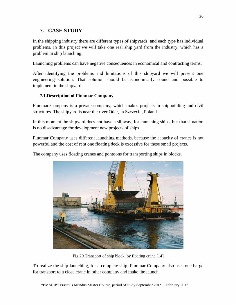
The company uses floating cranes and pontoons for transporting ships in blocks.
Fig.20.Transport of ship block, by floating crane [14]
To realize the ship launching, for a complete ship, Finomar Company also uses one barge
for transport to a close crane in other company and make the launch.

37 Edwin Salas
Master Thesis developed at West Pomeranian University of Technology, Szczecin
Fig.21.Ship launching by crane is shipyard [14]
But the principal problem is that for every launch it is necessary the certification by the
maritime authorities. This is necessary, because the shipyard is in a very transited place of
the river Oder, and the major disadvantage is the nearness of Szczecin terminal.[22]
This problem is common in other shipyard. The ship launching can be the cause of the
problems, for example the close of roadways. If the shipyard is close to river or canal, that
problem has directly relationship with economical and tariff ranges.
Fig.22 interruption of transit caused by the waves made for the launch process [9].
Those disadvantages make the launch of ship use a lot of time, and are a costly process,
because it becomes necessary to engage the service of other companies or organizations.
The analysis of the situation of this company found one possible solution.

38
“EMSHIP” Erasmus Mundus Master Course, period of study September 2015 – February 2017
8. CHARACTERISTIC OF TRANSVERSAL SHIP LAUNCHING
The process of transversal launching has different steps, and in every step use different
mechanical devices.
In this part we will describe the more important parts of these mechanical pieces.
The analysis of work and the mechanical pieces used in the process of ship launching is the
most important part for designing any solution for the ship launching, because after that we
will have a possible idea on how to develop the process of ship launching.
8.1.Ship position in the slipway
The position of ship relative to slipway is important, because it makes possible the
development of the future process for make the ship launching.
It is necessary to use the general requirements for the height between the bottom of hull
ship and slipway (next): it is possible to use 700 – 800 mm from bottom of ship to slipway
reel. This present 1000-1200 mm to slipway base and 1200 - 1500 between reels.(Fig.23)
But, in the shipbuilding experience is possible; find other measures for this description, for
example between 350- 700mm distance from the bottom to slipway reel
8.2.Retention device equipment.
This device is used for the retention of ship in the slipway at the moment of transference of
ship in the slipway to launching moment.
The retention device should be resistant and safe for work.

39 Edwin Salas
Master Thesis developed at West Pomeranian University of Technology, Szczecin
8.2.1. Mechanical retention device
This device has simple construction, low weight and dimension, but climate temperature
affects it.
There are fixed in couple, in every side of slip .The steps for operation of the device are
shown next:
The retention piece is one curve cam. This piece has the possibility to rotate out of the
structure and support the mobile piece of slip track with a special unbalanced lever.
In the inferior part the device has a cord to a command point or other special place of
slipway.
When the cord is cut, the lever falls and the curve cam set free to slip track and initiate the
movement.
The retention device has between 200 to 600 tn of retention force. The ship is detained with
big force by some couple retention device.

40
“EMSHIP” Erasmus Mundus Master Course, period of study September 2015 – February 2017
Fig.25.Trigger device in pre preparing launching [23]
Fig.26. Open Trigger device. It is possible to show the retention structure in the slip truck [23]
8.3.Slip truck in rollers
The launch is possible when the slipway is static launch way, so in this case it is a metallic
canal .The dimensions of canal is determined by launch weight of the ship. The canal is
welded to a piece of sheetmetal, and the width of the canal is less than the width of the
rollers. In this case it is possible to use a width of 300mm.
41 Edwin Salas
Master Thesis developed at West Pomeranian University of Technology, Szczecin
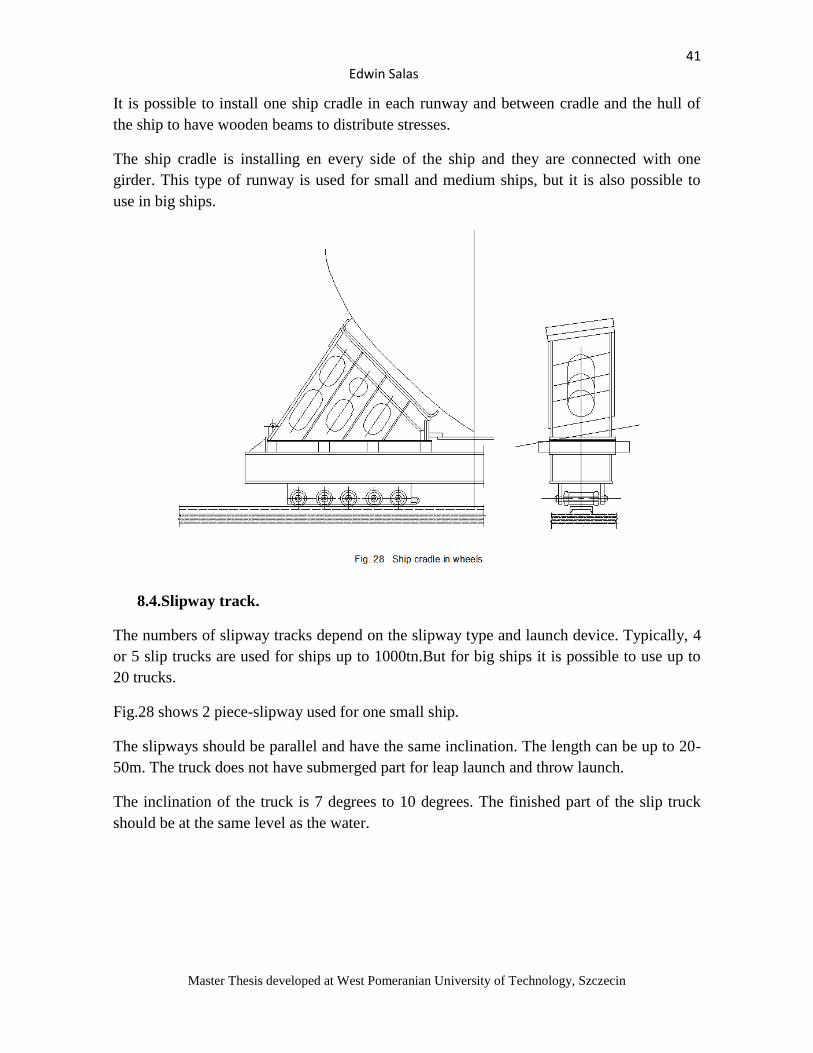
It is possible to install one ship cradle in each runway and between cradle and the hull of
the ship to have wooden beams to distribute stresses.
The ship cradle is installing en every side of the ship and they are connected with one
girder. This type of runway is used for small and medium ships, but it is also possible to
use in big ships.
8.4.Slipway track.
The numbers of slipway tracks depend on the slipway type and launch device. Typically, 4
or 5 slip trucks are used for ships up to 1000tn.But for big ships it is possible to use up to
20 trucks.
Fig.28 shows 2 piece-slipway used for one small ship.
The slipways should be parallel and have the same inclination. The length can be up to 20-
50m. The truck does not have submerged part for leap launch and throw launch.
The inclination of the truck is 7 degrees to 10 degrees. The finished part of the slip truck
should be at the same level as the water.

42
“EMSHIP” Erasmus Mundus Master Course, period of study September 2015 – February 2017
8.5.Characteristics of Slip Track
For transversal ship launching metal and wood are used. Metallic slip truck (fig 30), is used
in a T-Beam form, installed and welded in the structure. It is possible to install also pieces
of wood in the slip track. Finally, it is possible to use plastic plate and use that with any
lubricant.[24]
The length of slip truck has relation with the breadth of ship. It is possible to use a slip
truck from 0.8 to 1.5m more than the dimension of ship breadth.
The breadth of the slip truck is the same of slipway and cradle.

43 Edwin Salas
Master Thesis developed at West Pomeranian University of Technology, Szczecin
The work pressure in the slip truck is around 2-3.5 kg/cm2 and has direct relation with the
inclination of slip truck
The slip truck device for transversal launch has the following parts: slip truck, slip keel
blocks, girths, wedges, weight blocks, and retention device.
The construction of other parts and slip truck, has relationship with type and dimensions of
ship and characteristics of slipway.(See fig. 30 and fig.31).
For ship launching in series it is very common that the material of slip truck is metal. In the
slip truck have girths (if is necessary) between their wedges. In the girths keel blocks are
installed, and they have the cradle functions.
The metal keel block is fabricated with the form of the surface of hull ship and is installed
in the slip trucks.
Fig31.Slip truck device in job position [25]
8.6. Launch cradle
With a launch cradle (fig.32) it is possible to transfer all ship weight to slip truck, after
transporting to keel block. The ship cradle is made of metal or wood.
In a metallic cradle, pieces of wood are installed and fixed in the top part. The top part of
ship cradle is fabricated with the form of the hull of ship.

44
“EMSHIP” Erasmus Mundus Master Course, period of study September 2015 – February 2017
8.7.Girths and wedges
The girths are made of metal. They are the foundation for the wedges and ship cradle. In
the bottom part the girths have place for wedges, and in top part of him surface welded
protectors or holes for bolts for fixing the ship cradles.
To avoid uncontrollable movement of girths defenses are installed in the slip truck. The
breadth of girths and the slip truck is the same, and the length of girths depends of length of
keel blocks.
For transversal launch, use the same wedges than longitudinal ship launch. The angle of
wedges is not more than 3 degrees.
8.8.Lashing
This device is use to join the launch device to the hull of ship. The material is metal or fiber
plastic. The lashing use turnbuckles for fixation. The type of fixing depends of the form of
cradles and slip trucks.

45 Edwin Salas
Master Thesis developed at West Pomeranian University of Technology, Szczecin
Fig.34. Position of security lashing
The ship is moved in the cart only to the inclined part of the slipway, then the ship
launching is made after transfer to the multi roller car. The transfer of the ship to the multi
roller cart is made with metallic frames (Fig.36), and the finished part of incline slipway.
The transfer is possible in 2 steps:

46
“EMSHIP” Erasmus Mundus Master Course, period of study September 2015 – February 2017
The ship is transported on metallic frames to prevent the possibility of cross under bottom.
After transfer all the structures with the ship, installing in the launching position and
transfer to multi roller cart, the ship is launched.
8.9.Process of ship launching by slipway
In the transversal ship launching ,the most important characteristic is the inclination of the
ship relative of inclination of slipway and height of the ship in the plane of slipway.The
position of sliptruck of slipway has the same position of the frames or bulkhead of ship.
The process of ship launching in the inclined slipway can be divided in four periods:
1. Period from initial movement to aproximation to threshold of ship
2. Period from aproximation to threshold to moment of contactoof hull of the ship with
the water.
3. Period from contact of hull of the ship with the water to moment when the final part
of sliptruck has contacted with the threshold.
4. Free movement of ship by inertia to final stop.

47 Edwin Salas
Master Thesis developed at West Pomeranian University of Technology, Szczecin
The ship launching is realized in the launch device. Transversal launch is less dificult than
longitudinal launch,but it is necessary to think, from the moment of iniciation movement of
ship that process is not controlled. The most dangerous moment is no initial
synchronization movement in every truck. That problem can sag the ship.
In the initiation of ship launching, is activation of the force of gravity of ship and sliptruck
device, in perpendicular direction to slipway and ship movement, and frictional force
between the slip device and slipway.
Static and dinamic frictional coeficient have the same dimension than the longitudinal
launch.
In the moment contact sliptruck with water,will initiate appear the resistence force,in the
direction of movement of ship,and in the vertical direction ,will appear the boyancy
force,wich will increase ,when appear the inmertion of ship.
The ship debelovment one complicated movement , movement of center of gravity and
rotational relative to his axis in the center of gravity.When the ship it sinks and the ship
weigt and boyancy force is the same the ship have the normal floating.

48
“EMSHIP” Erasmus Mundus Master Course, period of study September 2015 – February 2017
CHAPTER II
9. PROCESS OF PROJECTING SOLUTIONS FOR SHIP
LAUNCHING
In the process of design, we will use the information of ship yard, their technical limitations
and other problems creating limits to the process of ship launching.
After that we will decide the next step for the solution of the problem.
It is necessary to understand the principal requirements of the ship launching process and
the basic requirements of shipyard for designing and developing one possible solution for
ship launching.
The limitations and requirement of shipyard are presented here:
1. Impossibility to make any construction in the ship yard
2. It is necessary to make the launching in other place, far from restricted areas of port.
3. It is necessary to find one solution for the difference in level of shipyard relative to
deck of pontoon
4. The possibilities make one ship launching, and not use floating cranes or floating
decks
5. Process should work for any ship size, small and medium ship
6. The process should be economic and require a short amount of time
7. The solution should be easy or not require to make contract with specialized
professional
For these requirements one solution will be presented, also that solution will be practical in
his application in the shipyard.

49 Edwin Salas
Master Thesis developed at West Pomeranian University of Technology, Szczecin
10. ANALYSIS OF PROBLEM
From this requirement, we understand, it will be necessary to use one transport to make the
ship launching, because it is not possible to make any launch maneuver near port.
The company has experience in the transport ships and block in pontoons. The problem is
to determine the correct level between shipyard and pontoon for transfer of the ship.
Other important thing is we can not use any floating crane or floating dock. This restriction
gave us the idea to design one device for the realizing the ship launching.
In this case, we will study the possibility to make launch of the ship from one pontoon. For
that, we will design the appropriate slipway which will be installed in the deck of pontoon.
After, we will analyze the dynamic process of launch of ship from one pontoon and one
structural analysis for the new type of slipway.
10.1. Ship launching from floating pontoon
After understand the main idea of all problems for development the ship launching, it is
decided to make the ship launching from one pontoon.
In the offshore industry, the floating pontoon is used for launch different types of
structures, but this launching is in type longitudinal and for very big structures, also it needs
special pompoms and other equipment.
In this project we will use one typical pontoon, which will not need to make any inclination
for ship launching. The process of ship launching will be by gravity force and transversal
type.
The position of the ship will be above the necessary number of portable slipways. That
slipway is installed in the deck of pontoon and those can be used afterwards for other ship.
The portal slipway will be easy in construction, installation and repairing, and have the
possibilities to change its height to be used in ships of different positions levels in the
shipyard.
10.2. Process of transfer the ship
The transfer from shipyard to pontoons will be possible with reels and rolls cart. That
process is actually in development for ship launching. Different shipyards have experience
in this process. That idea we will combine with initial requirement for solving the problem
of level between the shipyard and pontoon.
But we need to understand, we don’t have any possibility to make any ship launch near the
shipyard. Fig.37 presents the proposal of transversal launch from pontoon for this project

50
“EMSHIP” Erasmus Mundus Master Course, period of study September 2015 – February 2017

51 Edwin Salas
Master Thesis developed at West Pomeranian University of Technology, Szczecin

52
“EMSHIP” Erasmus Mundus Master Course, period of study September 2015 – February 2017
11. EQUIPMENT FOR TRANSVERSAL LAUNCHING FROM
PONTOON.
For this project it is necessary different types of devices, which will be in all the processes.
One principal idea is the possibility to use those devices for launching different types of
ships.
11.1. Pontoon
The pontoon is one of the principal pieces of equipment of this project. For the maneuver of
ship launch it is necessary to perform different preparation steps in the deck of the pontoon
(fix the support of slipway, preparation of launching).
The position of pontoon should be static at the moment of ship launching. It is possible also
to use one tug for movement in different directions of the ship, and also can use one tug for
the ship launching in different direction then pontoon.
Also it is possible to use more safety tugs, with can help in the ship launch. One tug can the
control of launch for the ship, and in pontoon side can realized the same auxiliary work.
Type ship LxB Weight(Tn)
Service ship 80x20 2000
Container ship 106x15 1350
Container ship 103x17 1400
Purse Seiner
Trawler 64x13,8 800
Fishering 70x12 775
Fishering 70x15 1000
Table. 2. Types of ship which are make in one small shipyard
From table 2, we decide use one pontoon LxBxT=65x18x3.8, because with this dimension
it is possible to make ship launching of more of the small and medium ships from this table.
For example the company Finomar has experience in transfer of ship from shipyard to
pontoon, and for that process uses reels and cradles.

53 Edwin Salas
Master Thesis developed at West Pomeranian University of Technology, Szczecin
Fig.38. Pontoon in statically position for making the transfer of ship [14]
11.2. Reels
The reels are structures used for transporting the ship from shipyard to pontoon (Fig.39).
They have holes where is possible install hydraulics pompoms, which work in coordination
for ship transfer.
The ships have supports or cradle in the canal formed by working with reels.
Between reels and ship supporting, we also will use one lubricant with good frictional
coefficient.
In the Fig.40, the process of transfer of ship to pontoon is presented.

54
“EMSHIP” Erasmus Mundus Master Course, period of study September 2015 – February 2017
Fig.39. Typical reels for transportation of ship to pontoon
Fig.40. Transference of ship to pontoon

55 Edwin Salas
Master Thesis developed at West Pomeranian University of Technology, Szczecin
11.3. Slip device
In this project, we developed the design parameters for this new type of slipway device.
This slipway device is a new type of slip truck that solves the process of transversal launch.
This slip truck is a type structure with outline specification for mechanical/hydraulically
equipment for a 1,000 ton capacity.
This solution gives us the possibilities to solve the problem of level difference between
shipyard and pontoon. We will use the necessary jacks in the sliptruck
Fig.41. Preliminary portable slip truck and slipway
The process of ship launching is shown in the next graphic. This instance has different step,
so what is necessary is a high accuracy.

56
“EMSHIP” Erasmus Mundus Master Course, period of study September 2015 – February 2017
Fig.42. Ship launching process from pontoon

57 Edwin Salas
Master Thesis developed at West Pomeranian University of Technology, Szczecin
12. DESCRIPTION OF PORTABLE SLIPTRACK
The new slipway can be used in the pontoons. The number of slipways, depends on the
weight of ship. For example for one ship of 1000tn it is approximately necessary 5 units.
The transversal launch, which is supported in one pontoon, has some characteristics.
The dimension of slip track depends on the dimensions of pontoon and the weight and
dimensions of small and medium ship. In table 1, we present the possibilities of ship
examples for use this slip track.
The time of work of this slip track is no more than 7 seconds.
Also it is necessary the use of an adequate lubricant between the ship cradle and slip truck.
The frictional coefficient should be between 0.17 to 0.2, for more safety during ship
launching.
In analogy of others slip ways for transversal launching, used in the ship building industry,
in this project the cradle and slip track are modeled in one structure.
That model give us the possibility to make a more portable structure, for use in the deck of
pontoon. Also with that model it is possible to use by different models of ship, because
every cradle has different positions in hull of ship.
Fig. 43 shows the one slipway for transversal launching
Fig.43.Slipway with different slip tracks [26]
In the fig.43, shows a proposal of slip track. In this design, we change the slip track and use
it at the same time as the cradle.

58
“EMSHIP” Erasmus Mundus Master Course, period of study September 2015 – February 2017
We decide to join the cradle and slip track, to make easy the launching and for recuperation
after the ship launching
Fig.44.Slip truck in the positions of transfer the ship
12.1. Characteristics of portable slip truck
This portable slip track has 3 principal parts. All parts are made of steel.
Fig.45. the positions of slip truck depend on the length of the ship [27]

59 Edwin Salas
Master Thesis developed at West Pomeranian University of Technology, Szczecin
Fig.46. Portable slip way
12.2. Slip track
The connection is in form of a canal for assembling with the ship cradle. That situation
gives the possibilities for the correct movement of ship to water, and can avoid the possible
rotation or other movement of ship and pontoon, at the moment of ship launching (Fig.47).
Also it has one rotating part, in this case one rocker arm, with rotate at the final part of
launching (Fig.48).
That element avoids collisions between cradle and slip track, and lessens the concentration
of stress in the slip track and cradle.(Fig.49)

60
“EMSHIP” Erasmus Mundus Master Course, period of study September 2015 – February 2017
Fig.47. Slip truck
Fig.48. Rocker arm

61 Edwin Salas
Master Thesis developed at West Pomeranian University of Technology, Szczecin
Fig.49.Slip way witch rocker arm [28]
12.3. Slip cradle
This part has a connection with the ship at all time and is removed after the launch. That
part is one construction with internal reinforcement, because is supporting all the weight of
the ship.
In the slip cradle we install the security trigger. It is necessary one in every side of slip
cradle.
Those triggers should be mechanical-electric, because it is necessary they work in the same
time.
At the initial moment of the ship launching, all triggers should be open.
The process of shoring of ship is made with ship cradles in different position of ship. Their
position was determined previously. This is necessary because the launching of the ship is a
dangerous moment in the construction of ship( Fig.50)

62
“EMSHIP” Erasmus Mundus Master Course, period of study September 2015 – February 2017
Fig.50. Cradle for medium part of ship
12.4. Supporting structure
That part supports and connects the structure of slipway and pontoon (Fig.51). In the
process of ship transfer to pontoon, this part should be installed and also the jacks should be
in the correct position for the descent of the ship.
The union between supporting and slip track is possible with necessary bolts in every side
of the slipway.
The connection with pontoon is possible with fix supporting in the deck of pontoon.
The capacities of hydraulic jacks depend of weight of ship. We need to design the hydraulic
system for the largest capacity. It is recommend to use more than 20 tn for every jack.
The structure of slip way is possible to be made in steel (Fig.52). In this case the project
uses one typical pontoon, and one ship of 1000 TN. It is also possible to design a bigger
model of slipway to make launch for different types of bigger ships. It is only necessary to
define the height of launch for other big model of slipway.

63 Edwin Salas
Master Thesis developed at West Pomeranian University of Technology, Szczecin
Fig.51. Supporting structure
After finish the design of portable slipway, it is possible determinate the weight for every
part and other physical characteristics (Table3).
It is necessary to know those structures were designed with 25mm of thickness. We take
that value because it has the maximum capacity for supporting the weight of ship and ship
launching. In the following structural analysis it will be possible to change the thickness of
any part to reduce the weight of the portable slipway structure.
Area(m2) Weight(Tn) Volumen(m3)
Cradle 119.80 11.80 1.50
Slip track 119.15 16.65 2.12
rocker arm 18.69 1.85 0.24
Reforcement 79.12 7.67 0.97
Total
Assemble 341.35 38.43 4.88
Table.3.Physical characteristics of portable slipway

64
“EMSHIP” Erasmus Mundus Master Course, period of study September 2015 – February 2017
Fig.
52
. Po
rtab
le s
lipw
ay in
po
siti
on
of
lau
nch

65 Edwin Salas
Master Thesis developed at West Pomeranian University of Technology, Szczecin
13. MODELING OF TRANSVERSAL SHIP LAUNCHING
We will use the stability theory for the barge and ship at the moment of launch.
In this case we will model the translation of the ship from the middle position in the
pontoon to the moment when the ship has contact with water.
For this analysis we will use the methodology for transversal ship launching, present in the
book ¨ Ship launching; A.A.Kurdyumov; 1966¨
But in this project we have the condition from one floating pontoon, which does not have a
connection with any supporting
13.1. Process of ship launching
In this type of ship launch, the slipway is perpendicular to diametric plane of ship.
For this launch, also we take the same nomenclature as the longitudinal ship launch.
The transversal launch has different steps
When the ship initiates the movement, it makes complex translational and rotational
movements, relative to an axis at the center of gravity.
After the opening of the security hammer, the movement is from the force of gravity, but it
is necessary to implement the next condition.
Where
We will project of force in the plane perpendicular to the direction of movement.
Then

66
“EMSHIP” Erasmus Mundus Master Course, period of study September 2015 – February 2017
The angle of slipway is little, then for the future estimation the take
and
Then, condition for the independent movement of ship is
Therefore, for initial movement of ship, is necessary, that inclination of slipway was more
them statically frictional coefficient of slip truck.
Then in the process of ship movement
For transversal launch in the initial translation to threshold is between 0.15 and 0.2 .That
value takes for the third period in the ship launching
The differential equation of movement of ship in the axis s
From relation and and
The result is
After apply integral in the II.7, and assuming what
is neglected, the result is
The time is excluding from in the last formulation and take length slipway of initial
position of diametric plane of ship to threshold is , and we find formulation for ship
velocity in the moment of translation of ship to pontoon
√
The information above is for typical transversal launching, but in this project it is possible
use that criteria.
67 Edwin Salas
Master Thesis developed at West Pomeranian University of Technology, Szczecin
13.2. Calculation of transversal ship launching from pontoon
Transversal ship launching from pontoon has different typical characteristics
We will present the calculation of positions of ship at the moment of ship launching.
The transversal ship launch from pontoon has seven periods
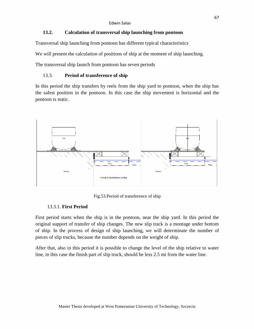
13.3. Period of transference of ship
In this period the ship transfers by reels from the ship yard to pontoon, when the ship has
the safest position in the pontoon. In this case the ship movement is horizontal and the
pontoon is static.
Fig.53.Period of transference of ship
13.3.1. First Period
First period starts when the ship is in the pontoon, near the ship yard. In this period the
original support of transfer of ship changes. The new slip track is a montage under bottom
of ship. In the process of design of ship launching, we will determinate the number of
pieces of slip trucks, because the number depends on the weight of ship.
After that, also in this period it is possible to change the level of the ship relative to water
line, in this case the finish part of slip truck, should be less 2.5 mt from the water line.

68
“EMSHIP” Erasmus Mundus Master Course, period of study September 2015 – February 2017
Fig.54.First Period
13.3.2. Second period
In this period the ship and pontoon are preparing for ship launching. There can be
transporting to other place, when it is safest to make that maneuver
Fig.55.Second period of launch

69 Edwin Salas
Master Thesis developed at West Pomeranian University of Technology, Szczecin
13.3.3. Third period
In this period, the ship initiates the movement of ship launching .The ship star realizes one
horizontal movement and its center of gravity rotates relative to its axis.
The movement of ship and pontoon is the result of gravity force. It is not necessary to make
any other maneuver.
Also it is not necessary to make any inclination in the pontoon
The finish of this period is when the ship initiates contact with the water.
The system ship-pontoon makes a very complex horizontal and rotational movement
relative to their center of gravity.
Fig.56.Thrid period of launch
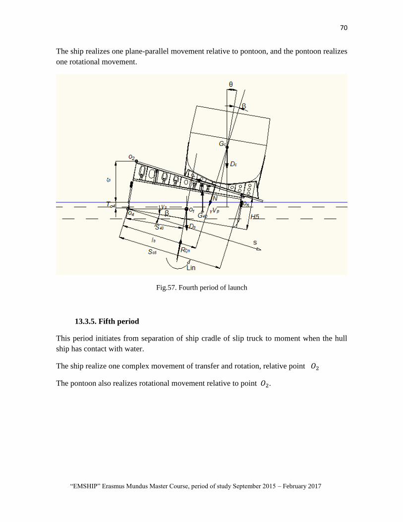
13.3.4. Fourth period
Movement of ship initiates from contact of hull ship with the water to moment when the
ship cradle initiates separation of slip truck by the rotation of ship.
70
“EMSHIP” Erasmus Mundus Master Course, period of study September 2015 – February 2017
The ship realizes one plane-parallel movement relative to pontoon, and the pontoon realizes
one rotational movement.
Fig.57. Fourth period of launch
13.3.5. Fifth period
This period initiates from separation of ship cradle of slip truck to moment when the hull
ship has contact with water.
The ship realize one complex movement of transfer and rotation, relative point
The pontoon also realizes rotational movement relative to point .

71 Edwin Salas
Master Thesis developed at West Pomeranian University of Technology, Szczecin
Fig.58.Fith period of launch
13.3.6. Sixth period
This period initiates when hull ship contacts with water and ends when finish part of ship
cradle is separated from the slip truck.
The ship has movement in the water, a movement is the same type of five period.
Fig.59.Sixth period of launch

72
“EMSHIP” Erasmus Mundus Master Course, period of study September 2015 – February 2017
13.3.7. Seventh period
Free inertial movement of ship to water from initial angular and lineal velocity to total
stopped.
The ship makes plane-parallel movement
Fig.60.Seventh period of launch

73 Edwin Salas
Master Thesis developed at West Pomeranian University of Technology, Szczecin
14. DYNAMIC THEORETICAL ANALYSIS
To verify the possibility of realizing the ship launching a modeling of this process will be
made, considering a ship, a pontoon and a respective portable slipway.
With this equipment, we will model the dynamics of ship launching, obtaining the most
important characteristics for this process.
After that, also, it is possible to make a structural analysis of the portable slipway, from
where we will obtain the regions where there is the highest concentration of stress
Gravity force, frictional force and normal reaction in the slip truck appear in the ship and
pontoon in the all periods of ship launching.(the frictional force and normal reaction finish
disappear at the start of the seventh period). Also, the ship resistance force and sustentation
force appear in the pontoon on the third period. The buoyancy force and ship resistance
force also appear on the sixth and seventh period.
It is possible to show an exact formulation movement system pontoon-ship in polar
coordinate for Lagrange method, taking into account all forces:
For third and fourth period of ship launching:
For fifth and sixth period of ship launching:
For seventh period of ship launching:

74
“EMSHIP” Erasmus Mundus Master Course, period of study September 2015 – February 2017
In this formulation, it is possible to determine the relationship between coordinates,
velocity and parameters, for calculating buoyancy force, stability and ship resistance of ship
and pontoon in the process of ship launching.
In this project we will present one approximate solution
This approximate solution is possible for next condition:
- Inertial force and moment of ship to pontoon is neglected. Ship is calculated as one
material point, which appear in the pontoon with force equal reaction in the slip
truck.
- The movement of the pontoon, is the same movement of body in constant slope
- Force and moment from ship resistance is neglected.
- Horizontal force from ship resistance is also neglected.
- It is assumed that the rotation of pontoon in the third period is in the axis across the
center of gravity, also vertical sinking of pontoon is neglected.
- The sinking of pontoon in the third and fourth periods is constant. The inclination of
pontoon in the third and fourth period is the same volume.
- The pontoon in the fifth and sixth period launching is immobilized and height of
threshold is the same as at the finish of the fourth period.
In the second period, fig.55 shows the force in the system, which rotate relative to axis .
The formulation for rotation equation of movement of the pontoon relative to axis , is
show
Where
Then, by inertial moment mass theorem relative parallel axis
Where

75 Edwin Salas
Master Thesis developed at West Pomeranian University of Technology, Szczecin
The axis in the initiation in the point in the deck of pontoon
Moment of angle of list of pontoon is
Where
For small slip truck slope , then
Then, with all requirements
We know also
√
Where

76
“EMSHIP” Erasmus Mundus Master Course, period of study September 2015 – February 2017
From relationship II.17 to II.15, and II.15 to II.13 and change N by , we will obtain the
next relation
*
+
In the initial position
And
Where
Elevation of center of gravity of pontoon from center of buoyancy in the initial position
Where coordinate
is measured from base line of pontoon.
In the inclination of pontoon relative axis will create one
negative buoyancy moment, and additional sinking in the pontoon, in this case positive
buoyancy moment.
Then
Where

77 Edwin Salas
Master Thesis developed at West Pomeranian University of Technology, Szczecin
From fig.56
Where
The center of buoyancy of volume is in the center of gravity in the trapeze fig.56 .Is
possible take is equal distance of center of gravity of OBC to point O.
(
)
If equations II.23 and II.22 to II.21, the result is
(
)
Designate
(
)
Receive
The necessary landing of pontoon before ship launching is possible after take water in
ballast. The free surface ballast in tanks less the restoring moment in the measure equal the
next add.
[ ∑ ]
Where
The equation II.20, II25 and II.26 in II.19 and change and we will receive
( ∑
)

78
“EMSHIP” Erasmus Mundus Master Course, period of study September 2015 – February 2017
Moment of inertial force of water resistance, applied in the pontoon in the axis
Adding mass
, for vertical and lateral pitching of pontoon, it is possible to take
equal approximation
If the equation II.29 and II.30 in II.28, the solution is
(
)
In the relation II.18 and II.27 and II.33 in the initial equation II.11, after the
accommodation, the solution is
where

79 Edwin Salas
Master Thesis developed at West Pomeranian University of Technology, Szczecin
∑
The equation II.34 .is lineal differential equation of second degree is constant coefficient.
Their solution is the sum of two equations
The generally solution of equations is
This is particular solution
For find the coefficient we will use the next relation
That equation in II.34, we get
From those relations, we get
80
“EMSHIP” Erasmus Mundus Master Course, period of study September 2015 – February 2017
From those relations we get the angle of inclinations of pontoon
The angular velocity of pontoon is from derivative of equation II.41
The constant is get from equations II.41 and II.42, which define the initial situation
of movement
In the initial of second period for ,this conditions in equation II.41
and II.42,we get
At the finish of second period, the cradle begins the separation of slip truck. Here we
neglect inertial force in the ship and pontoon, also inertial force from water resistance,
applicant to pontoon; we will take, which this separation begins when:
And
If equation II.18 and II.27 is equal and change in the equation II.22, after we get
Where p and q are coefficient

81 Edwin Salas
Master Thesis developed at West Pomeranian University of Technology, Szczecin
(
∑
)
From the positive result, we get
√(
)
Which determines the end of the second period.
In the third period, the pontoon by the force of gravity rotates relative to axis , passing
by center of gravity of pontoon. The same which the second period, the differential
equation of rotate movement of ship is:
In the beginning axis s in the third period, take in the center of gravity of pontoon. The
moment of inclinations of pontoon, relative axis
Where
The coordinate of center of gravity of ship
Where
After differentiating the equation II.15, we get

82
“EMSHIP” Erasmus Mundus Master Course, period of study September 2015 – February 2017
That information in the fig.57
Where
The equation II.50 and II.52 to II.49, we get
*
+
Inertial moment of sustentation of pontoon relative axis is possible to determine by
metacenter equation. With the consideration of free surface of water in the ballast tanks of
pontoon.
( ∑
)
Where
Where
For box pontoon

83 Edwin Salas
Master Thesis developed at West Pomeranian University of Technology, Szczecin
In this case is measure in the diametric plane of pontoon.
Equation II.62 to II.61,and II.61 and II.60 to II.59,we get
[ (
) ∑ ]
The inertial moment force of water resistance
Adding the mas and take the second grade
The equations II.55 and II.63 and II.64 to equation II.48, we get
Where
* (
) ∑
+

84
“EMSHIP” Erasmus Mundus Master Course, period of study September 2015 – February 2017
In The equation II.65 by analogy in the second period (II.34). It is possible to make the
solution
It is necessary to find the constant and .
In the beggining of third period that information in the equation
II.41 and II.42.then
At the finish of third period, the point A and the center of gravity move , in opposite
direction of the ship. That movement is the result from two forces; Force N – the pressure
of ship to pontoon and buoyancy force of sinking volume of pontoon, in the second period.
The pontoon is pushed by the last force from water.
The equation of horizontal move of center of gravity of ship is
In the position N, we change by equation II.50, then
Where
(
)
On integral equation II.74, then

85 Edwin Salas
Master Thesis developed at West Pomeranian University of Technology, Szczecin
For find used the initial condition for
Where
Is fig.56,
From initial condition to equation II.76 and II.77
Then
For , we get
Where
With the positive solutions we can find time and final moment of finish of the third period.
For find ,

86
“EMSHIP” Erasmus Mundus Master Course, period of study September 2015 – February 2017
* (
) +
Where
In the fourth period (fig 57), rate in axis ,passing by pontoon
The equation of rotate movement is
Coordinate s in the four period is relative from
Inertial moment of mass relative axis
Where
Moment of inclinations, which appear in the pontoon relative axis (fig.57)
Where
The distance tale constant, and is the same as the finish of third period
From fig.57, show
If angle

87 Edwin Salas
Master Thesis developed at West Pomeranian University of Technology, Szczecin
Then
Coordinate of center of gravity of ship
Where
After differentiating II.52, we get
Is fig.57,show
The equation II.90 and II.94 to equation II.89, then
*
+
The moment of force sustentation of pontoon relative axis , with free surface of water
in the ballast tanks
[∑ ]
Where
The expression for the distance is:
Where

88
“EMSHIP” Erasmus Mundus Master Course, period of study September 2015 – February 2017
It is possible to find the metacentric height of the same steps than in third period. Then
after the transformations we get
[
(
) ∑ ]
Inertial moment of force of water resistance (fig.57)
Can express by adding mass, we get
Adding the mass
and there are the same than in second period
The equations II.102 and II.103 to II.101
(
)
The equation II.97 and II.98 and II.104 to equation II.87, then

89 Edwin Salas
Master Thesis developed at West Pomeranian University of Technology, Szczecin
( )
* (
) ∑
+
The equation II.105 is analog equation in the second and third period. At this moment is
necessary find
In the beginning of fourth period for the equation II.41 and II.42
In the finish of fourth period beginning the separation of ship from pontoon. At this
moment the inertial force and force of gravity are the same.
Where
From fig.57
Where
If the equation II.113 in the place, s in equation II.94, we get
90
“EMSHIP” Erasmus Mundus Master Course, period of study September 2015 – February 2017
Where
( )
The positive solution gives the time and moment of finish the fourth period
The velocity of center of gravity of ship in the finish of fourth period is possible with the
equation II.94
Then
The height of boundary in the moment of finish the fourth period, we can see in the fig.57
Where
*
+
In the five period the pontoon is static, and after the movement of ship is the same them
transversal ship launching. But in the finish of fourth period the ship has angular velocity
and inclination angle.
By the relation between ship and pontoon, the angle of inclination of ship in the finish of
four period is the same then inclination angle of pontoon, ,angular velocity of ship is
the same then angular velocity of pontoon .Is this reason, why in the five period we
have new initial situation. Then for normal transversal launching
Velocity
Coordinate
[ ]

91 Edwin Salas
Master Thesis developed at West Pomeranian University of Technology, Szczecin
Where
velocity
Where
Inclination angle
(
)
Angular velocity
(
)
(
)
The sixth and seventh period is one normal transversal ship launching

92
“EMSHIP” Erasmus Mundus Master Course, period of study September 2015 – February 2017
15. DINAMIC SIMULATION OF SHIP LAUNCH
For determining the dynamic characteristics of pontoon in the process of launch of ship, we
will model, this process with Matlab language applicant by the dynamic theory for
transversal ship launching.
For that process we will use one typical model of ship and pontoon. It is possible to apply
the resultant of this model for launch of different types of ship.
But the principal idea is for launch of small and medium ship, which is common for small
shipyards. The matlab modeling and resolve is presented in the Annex 1
For initial information for this modeling we will use:
L[m]=85
B[m]=12
T[m]=3.5
H[m]=5
Dc[tn]=1000
This ship has the characteristics of a ship built or repaired in a small shipyard.
The pontoon will be a typical model, which can comply with the process of ship launching
as well as transport the ship without problems.
This pontoon will have the following characteristics:
Lp[m]=65
Bp[m]=18
Tp[m]=2.5
With the characteristics of the ship and pontoon, is possible to choose the suitable portable
slipway.
For the portable slipway we use structural steel of 25 mm thickness and its dimensions will
be:
L[m]=18
B[m]=1.6
Slope[grades]=7

93 Edwin Salas
Master Thesis developed at West Pomeranian University of Technology, Szczecin
16. NUMERICAL ANALYSIS OF STRUCTURE OF SLIPWAY
We will realize the numerical structural analysis, for every part of the device, we will also
analyze the assembly.
For this analysis we will use the basic FEA (Finite Element Analysis) of software Autodesk
Inventor. This portable slip way haa one preliminary structure and weight for every pieces.
After this numerical analysis, we have the possibility to change the structures to reduce the
weight of slip way or improve the safety this device.
The most important part of this analysis, we will find the regions where is the maximum
stress and fatigue
In this case we will use one loads of 200 tn for every portable slipway, that value is the
maximum for this structure, and for large time will apply to assemble.
The modeling in FEA and resolution is presented in the Annex 2
We will also make the simulations for the portable slipway in the down position, when use
the jacks for change level of ship. That process is performed near of shipyard for more
safety
In this case the support will be for jacks. In this case every jack will support average
40Tn.
For this modeling is no necessary to analyze the support because the point of higher
concentration of stress is in the jacks and their internal support in the slip truck.
Also it is necessary to determinate which jack is needed and how much is the level of
down.
The result is show in the Annex 3

94
“EMSHIP” Erasmus Mundus Master Course, period of study September 2015 – February 2017
17. RESULTS
From dynamic simulations of ship launch, it is possible affirm, the ship launching process
is safe.Fig.61; the pontoon has 10 maximum degree in the point the maximum inclination.
With this angle the returned process is also safe
The stability of ship in the launching process is in the normal range for this type of
maneuver.
Also we can determine the velocity of pontoon, in this case is 6m/s. This value is
acceptable for return to the initial positions of pontoon.
The angular velocity of ship at the moment of launch also is determined to be 0.2rad/s.
The time of process is 6 second, which is also acceptable for this process
We should know that although this process is very fast, in this case the stability of ship in
the launching process is in the normal range for this type of maneuver.
Fig.61Dynamic Modeling of Ship Launching
From the stress in the structural analysis (Annex 2), it is possible to determine the
maximum point of stress. In this case it is in the region near of second jack, and has a value
of 35.51MPas (Fig.62,Fig63)

95 Edwin Salas
Master Thesis developed at West Pomeranian University of Technology, Szczecin
Also we understand, what in that place is necessary will be careful because the von misses
stress is maximum.
The maximum first Principal Stress is in the cradle, in the union of plates in the top, where
has directly contact with ship or pieces of wood. The value is acceptable in this case is
26.96MPas.(Fig.64)
The maximum third Principal stress is also in the same region of the maximum First
Principal, and the value is 11.29Mpas.
The displacement maximum is 0.51mm in the top plate of cradle, that value is
acceptable.(Fig.65)
Also the safety factor maximum is 15 and minimum is 9.86.(Fig.66)
With that value it is possible verify the safety of construction of portable slipway.
From the FEA when in down position ( Annex 3), it shows the region where the stress is
maximum, in this case the connection of support of jacks.Fig.67-70
Annex 4 shows the plans for this portable slipway. It is possible to change the dimensions
in that model for other types of barges or ships. In this case that model is the best for one
small shipyard
Fig.62 Maximum Von – Mises Stress

96
“EMSHIP” Erasmus Mundus Master Course, period of study September 2015 – February 2017
Fig.63 Point of Maximum Von – Mises Stress
Fig.64 Maximum 1st Principal Stress

97 Edwin Salas
Master Thesis developed at West Pomeranian University of Technology, Szczecin
Fig.65 Maximum point of Displacement
Fig.66 Minimum point of Safety Factor
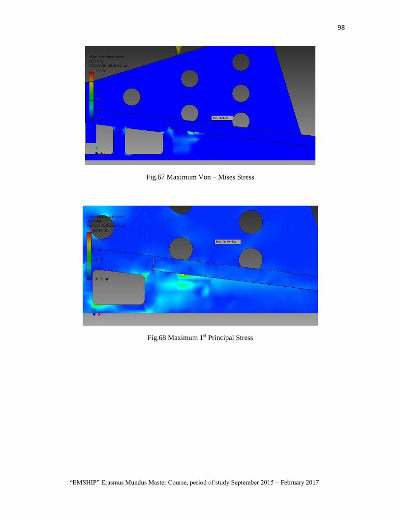
98
“EMSHIP” Erasmus Mundus Master Course, period of study September 2015 – February 2017
Fig.67 Maximum Von – Mises Stress
Fig.68 Maximum 1st Principal Stress

99 Edwin Salas
Master Thesis developed at West Pomeranian University of Technology, Szczecin
Fig.69 Maximum point of Displacement
Fig.70 Minimum point of Safety Factor

100
“EMSHIP” Erasmus Mundus Master Course, period of study September 2015 – February 2017
18. CONCLUSIONS
In every ship yards optimization of economic efficiency is of paramount importance, even
more in the current shipping industry market conditions, therefore it follows that efforts
should be taken to improve the efficiency in each of the productive processes. Most
conventional shipyards are large scale operations, which means that most large ship yards
have carefully studied and developed their ship launching procedures.
Launch procedures may still present difficulties for small ship yards so in this project we
are presenting a special case where the ship launch, which is a major task, can have an
acceptable efficiency.
The ship launching procedure presented in this thesis, elaborated by the Author as
an original idea, may be applied in different types of ship yards in different regions of the
World. More importantly, this procedure may be used in ship yards with launch problems
or located in seas, lakes or rivers with traffic difficulties near the ship yard.
With this methodology it is possible to model the launch process even when the slipway,
floating dock or cranes are busy, unavailable or tied up on other tasks. Also, this
methodology can be used for launching metallic structures like construction blocks for the
offshore industry. This methodology is a new resource for the shipyard because it can free
space at the shipyard by transferring the ship being build or repaired to a different location
for launch. This methodology is flexible enough so it can be applied to all kinds of ships
and on the majority of shipyards, specially small shipyards. As ships can be transferred
away from the shipyard it is no longer necessary to get a permit or authorization from
maritime or port authorities, which makes the launch no longer dependent on them.
An important result of this project is that the cost is comparatively low versus other launch
methods, as the equipment has a low cost and can be used repeated times. The design of
the portable slipway allows for ship launch avoiding an impact or damage between the ship
and the floating pontoon. The design allows for transferring the ship to the floating
pontoon regardless of the water level, because jacks will adjust the level of the portable
slipway.
Finally, this method requires less time for ship launch which reduces the cost because it
only requires an appropriate floating pontoon and maybe tugboats. Cranes or a floating
dock are no longer required.

101 Edwin Salas
Master Thesis developed at West Pomeranian University of Technology, Szczecin
19. ACKNOWLEDGEMENTS
I would first like to thank Coordinator of Program Emship,Professor Philippe Rigo, who
give me the opportunity of realize this master and can increase my knowledge in naval
architecture
I extend my gratitude to all the Professors, lectures and staffs of University of Liège, École
centrale de Nantes and West Pomeranian University of Technology, for all their support
during all steps of study and residence in every country during the program Emship.
I would like to tell my appreciations to Mr.Michał Gołębiowski and all specialist of
Company Finomar-Szczecin for the technical information, guidance and supports during
my intership and the preparation of this thesis.
Special thanks to Prof. Tadeusz Graczyk, Prof. Zbigniew Sekulski and Prof. Maciej Taczala
of ZUT for. their constant opinions, recommendations and contributions for write my
master thesis
I will always appreciate to Professor Prof. Tadeusz Graczyk,, my supervisor at ZUT, for the
motivation, guidance during the development of project of thesis also given thank to Prof.
R. BRONSART and Prof. A.HAGE, for reviewing this work
This thesis was developed in the frame of the European Master Course in “Integrated
Advanced Ship Design” named “EMSHIP” for “European Education in Advanced Ship
Design”, Ref.: 159652-1-2009-1-BE-ERA MUNDUS-EMMC.

102
“EMSHIP” Erasmus Mundus Master Course, period of study September 2015 – February 2017
20. REFERENCES
1. Conceptual Design of a Mechanized Shipyard for Fast Deployment Logistics(x)
Production; Benjamin V.Andrews,et al Stanford Research Institute; Bureau of Ship
;1965
2. Ship production; Second Edition; Richard Lee Storch; Maryland; 1995, pag.46
3. - Shipbuilding Industry Set to Pick Up After 2017
;http://worldmaritimenews.com/archives/179125/shipbuilding-industry-set-to-pick-
up-after-2017/
4. Top 16 Events that Impacted Tanker Shipping in 2016;
https://www.mcquilling.com/blog/2016/
5. The Tanker Orderbook; https://www.mcquilling.com/blog/the-tanker-
orderbook.html
6. Shipyards struggle amid market downturn;
http://www.marinelog.com/index.php?option=com_k2&view=item&id=22047:ship
yards-struggle-amid-market-downturn&Itemid=230
7. Basic technology of ship construction;V.D.Matskevich; Sudostroenia; Leningrad,
1980. (In Russian)
8. 24 Most Insanely Satisfying Ship Launching Ever Recorded;
https://www.youtube.com/watch?v=UWDSWD2afqc&list=PLFTbjpS1uV-
S0FnoYzy5AaAFGrBoiSJsK&index=106
9. Big Ship Launch Fails Compilation 2016 HD;
https://www.youtube.com/watch?v=d5JThDbF4ow&index=113&list=PLFTbjpS1u
V-S0FnoYzy5AaAFGrBoiSJsK
10. Shandong Nanhai Airbag Engineering Co.,Ltd; http://www.airbag.cc/
11. FAYARD DRY DOCKING VIDEO; https://www.youtube.com/watch?v=zfYZOn-
I-Ms
12. Floating dry dock accidents involving transverse bending failure of the pontoon;
pag 1 ; R.E. Heger, Heger Dry Dock, Inc., USA; Royal Institution of Naval
Architects, ©2003.
13. Logos Hope 2012 Dry Dock In Subic Bay, Philippines;
https://www.youtube.com/watch?v=VBZCCyFaQLs
14. Finomar; http://www.finomar.com.pl/
15. Gondwana Marine Services (Seychelles) - 150t Travel Lift;
https://www.youtube.com/watch?v=LEQD54PSXyE
16. http://www.sperryaward.org/Sperrybrochure2002.pdf
17. New 4,500 Tonne Rolls-Royce Syncrolift Installed in Vietnam;
http://gcaptain.com/4500-tonne-rolls-royce-syncrolift/
18. http://fgg-web.fgg.uni-lj.si/~/pmoze/esdep/master/wg15a/l0300.htm
19. Launch of jacket ;http://fgg-web.fgg.uni-lj.si/~/pmoze/esdep/master/wg15a/l0100.htm

103 Edwin Salas
Master Thesis developed at West Pomeranian University of Technology, Szczecin
20. Ship launching; A.A.Kurdyumov, A.A.Gaysenok; Sudostroenia; Leningrad, 1966.
(In Russian)
21. Big Ship Launch Compilation HD 2015;
https://www.youtube.com/watch?v=UVBulzce0Oc&list=PLFTbjpS1uV-
S0FnoYzy5AaAFGrBoiSJsK&index=79
22. .REGULATION NO. 3 of the Director of Maritime Office in Szczecin of 26th July
2013;§ 162.; http://www.ums.gov.pl/prawne/porte.pdf
23. .Launching 1700 TEU Container Ship OS Samsun and Keel laying;
https://www.youtube.com/watch?v=faV2j9gihZ8
24. https://prezi.com/g5jazam5i54c/ship-launching/
25. Спуск кораблей на воду;
https://www.youtube.com/watch?v=RfpmV2OeDFM&index=98&list=PLFTbjpS1u
V-S0FnoYzy5AaAFGrBoiSJsK
26. Navy Christens Future USS Detroit;
https://www.youtube.com/watch?v=n6u4WjYaX2Q&list=PLFTbjpS1uV-
S0FnoYzy5AaAFGrBoiSJsK&index=84
27. . http://breakingdefense.com/2015/07/lcs-production-surges-prices-drops/
28. LCS 7 Detroit Side Launch; https://www.youtube.com/watch?v=-
WPE_4bqQXc&list=PLFTbjpS1uV-S0FnoYzy5AaAFGrBoiSJsK&index=82
.


1 Edwin Salas
Master Thesis developed at West Pomeranian University of Technology, Szczecin
ANNEX 1 Matlab cod of Modeling of Ship Launch

2
“EMSHIP” Erasmus Mundus Master Course, period of study September 2015 – February 2017
clc,clear all
% % -------------------------------------------------------------------- % % -------------------------------------------------------------------- % % Modeling of transversal ship launching from potoon % % -------------------------------------------------------------------- % % --------------------------------------------------------------------
% DATA OF PONTTON Dp=2500; % D_p = Weight of displacement of pontoon (tn) Lp=65; % L_p = Lenght of pontoon(m) Bp=18; % B_p = Breadth of pontoon(m) Tp=2.5; % T_p = Draft of pontoon(m) Hp=3.0; % H_p = Depth of pontoon(m)
% DATA OF SHIP
Dc=1000; % D_c = Weight of ship in launching (tn) L=85; % L = Lenght of ship(m) B=12; % B = Breadth of ship(m) T=3.5; % T = Draft of ship(m)
% DATA OF SLIPTRACK
beta=0.125; % a = Slope of slipway track fd=0.04; % f_d = Coefficient of dynamic friction hx=0.5; % diference of level by jacks
% OTHERS DATA
sigma=1; % sig=Specific weight of water (m) g=9.81; % Gravity force
% % -------------------------------------------------------------------- % % Calculation % % --------------------------------------------------------------------
Eo=Hp-Tp+Bp*tan(beta)+hx; % E_0 = Distance from the
axis O2 to the water horizon (m) h2=0.5*(T+Bp*tan(beta)+hx)*cos(beta); % H_2 = Elevation ot the
center of gravity over axis ¨s¨ in second period (m) hk=h2; % H = Elevation ot the
center of gravity over slip plane (m) (take iqual H2) H5=Hp+hx; % H_5 = Height on side of
pontoon from the bottom up to the threshold (m) s1x=0; % s_1 =Lenght of part of
coast where is located the slipway track(m) e=0.0001; % e = Separation of
axis of coast abutments to wall (m)(Take e=0)

3 Edwin Salas
Master Thesis developed at West Pomeranian University of Technology, Szczecin
lA=Hp+hx+Bp*tan(beta); % l_A = Separation of hull
of pontoon from axis of coast abutments (m)(Take lA maximun Eo) lb=Bp; % l_b = Distance of
tranfer of moment of inertia of mass of pontoon relative to axis O_4 x
(m)(Take lb maximun Bp) H2p=0.5*(hx+Hp+Bp*tan(beta)); % H_2p = Length of the
perpendicular lowered from the center of gravity of the pontoon over the
slip plane (m) zGp=0.5*Hp; % z_(G_p ) = Ordinate of center
of gravity of the potoon (m) JGp=Dp*Bp*Bp/g; % J_(G_p ) = Moment of inertia
of mass of potoon relative to central axis passing through center of
gravity (tn.m.s^2) lGp=((Eo)^2+ (0.5*Bp)^2)^(0.5); % l_(G_p ) = Distance of
transfer of moment of inertia of mass of potoon relative to axis O_2 x
(m) nGp=0.5*Bp; % n_(G_p ) = Separation of
center of gravity of potoon to axis O_2 (m) ap=0.5*(Bp-Tp); % a_p = Elevation of
center of gravity of potoon over his center of buoyancy in initial
position (m) sGp=0.5*(((Bp*tan(beta))^2+Bp^2)^(0.5))+0.5*(Hp*Bp*tan(beta))*sin(beta);
% SG_p = Distance from the point O_2 to the perpendicular lowered on
slip plane (m) summ=(1/12)*Tp*Bp^3; % s(n=1)^m?X_X = Sum of the
moments of inertia of the free surface area relative to the central
axis,perpendicular to the slip plane (m^4)
% First period % % -------------------------------------------------------------------- S1=((2*g*(beta-fd)*s1x)^(0.5));
velos2o=S1;
% Ship position relative to pontoon s2o=(-1)*(h2*beta);
% Second period % % --------------------------------------------------------------------
% Inertial moment of potoon,relative to axis O2x Jpo2=JGp+(Dp/g)*((lGp)^2);
lamdaoE=(3.1416/8)*(sigma/g)*Lp*((Bp)^2);
lamdaoO=(1/81.5)*(sigma/g)*Lp*((Bp)^4);
kVp=sigma*Lp*Bp*nGp*(2/3)*(nGp+0.5*Bp);
J=Jpo2+lamdaoE*(nGp^2)+lamdaoO;

4
“EMSHIP” Erasmus Mundus Master Course, period of study September 2015 – February 2017
a=Dc*g*((beta-fd)/(2*J));
b=Dc*velos2o/J;
c=Dc*h2*beta/J;
k2=(kVp-Dp*ap-sigma*summ)/J;
B2=a/k2;
B1=b/k2;
Bo=(-1)*(c/k2)-(2*a/k2^2); %
C1=Bo*(-1); %
C2=((-1)*B1)/(k2^(0.5)); %
p=2*velos2o/(g*(beta-fd));
q=(-1)*(2*(h2*beta+(kVp-Dp*ap-sigma*summ)/(sigma*Lp*Bp*nGp)))/(g*(beta-
fd));
% Time of second period t2=(-1)*0.5*p+(((0.5*p)^2)-q)^(0.5);
kt=(k2^(0.5))*t2;
ktgrad=360*kt/(2*3.1416);
comkt=180-ktgrad;
argcoskt=cos(kt);
argsinkt=sin(kt);
v2=C1*cos(kt)+C2*sin(kt)+Bo+B1*t2+B2*(t2^2);
% Angle of heel of pontoon in the finish of 2 period (grades) v2grad=v2*360/(2*3.1416);
% Angular velocity of pontoon in in the finish of 2 period (rad/sec) velov2=(-1)*(k2^(0.5))*C1*sin(kt)+(k2^(0.5))*C2*cos(kt)+B1+2*B2*t2;
% Position of pontoon in the finish of 2 period s2=0.5*g*(beta-fd)*(t2^(2))+velos2o*t2+s2o;
% Velocity of ship in the finish of 2 period velos2x=g*(beta-fd)*t2+velos2o;

5 Edwin Salas
Master Thesis developed at West Pomeranian University of Technology, Szczecin
velos3o=velos2x;
% Thrid period % % --------------------------------------------------------------------
% Ship position in the initial of thrid period (m) s3o=s2-sGp;
% Displacement of potoon in the finish of second period (m3) Vp2=(Dp/sigma)+Lp*Bp*nGp*v2;
J1=JGp+lamdaoO;
fi=beta+v2;
figrad=fi*360/(2*3.1416);
argcosfi=cos(fi);
argsinfi=sin(fi);
a1=Dc*g*cos(fi)*(sin(fi)-fd*cos(fi))/(2*J1);
b1=(Dp*cos(fi)*velos3o)/(J1); %
c1=(Dp*cos(fi)*s3o)/(J1); %
k21=sigma*(Vp2*(Lp*(Bp^3)/(12*Vp2)+Vp2/(2*Lp*Bp)-zGp)-summ)/J1;
B21=a1/k21;
B11=b1/k21;
Bo1=(c1/k21)-(2*a1/(k21^2));
C11=v2-Bo1;
C21=(v2-B11)/(k21^(0.5));
deltayp=lA*cos((acos((nGp-0.5*Bp)/lA)+v2))-e;
deltaVp2=Lp*Bp*nGp*v2;
D=0.5*g*sin(2*fi)*(Dc+sigma*deltaVp2)/Dp;
% Coordinat center of gravity of potoon in the finish of second period
(m) zp2=sGp*sin(fi)+H2p*cos(fi);
% Horizontal velocity of center of gravity of potoon in the finish of
second period (m/s)

6
“EMSHIP” Erasmus Mundus Master Course, period of study September 2015 – February 2017
veloyp2=zp2*velov2;
p1=2*veloyp2/D;
q1=(1)*2*deltayp/D; %
% Time of thrid period (s) t3=(-1)*0.5*p1+(((0.5*p1)^2)-q1)^(0.5); %
kt1=((k21)^(0.5))*t3;
kt1grad=360*kt1/(2*3.1416);
comkt1=180-kt1grad;
argcoskt1=cos(kt1);
argsinkt1=sin(kt1);
v3=C11*cos(kt1)+C21*sin(kt1)+Bo1+B11*t3+B21*(t3^2);
% Angle of heel of pontoon in the finish of 3 period (grades) v3grad=360*v3/(2*3.1416);
% Angular velocity of pontoon in in the finish of 3 period (rad/sec) velov3=(k21^(0.5))*C11*sin(kt1)+(k21^(0.5))*C21*cos(kt1)+B11+2*B21*t3;
% Ship position of ship relative of center of gravity of pontoon in in
the finish of 3 period (m) s3=0.5*g*(sin(fi)-fd*cos(fi))*(t3^2)+velos3o*t3+s3o;
% Velocity of ship in in the finish of 3 period (m/s) velos3x=g*(sin(fi)-fd*cos(fi))*t3+velos3o;
% Four period % % --------------------------------------------------------------------
velos4o=velos3x;
Jpo4=JGp+Dp*(lb^2)/g;
s4o=0.5*Bp-zGp*beta+s3;
so5=Bp-H5*beta;
fi2=beta+v3;
fi2grad=fi2*360/(2*3.1416);
argcosfi2=cos(fi2);
argsinfi2=sin(fi2);

7 Edwin Salas
Master Thesis developed at West Pomeranian University of Technology, Szczecin
J2=Jpo4+0.25*lamdaoE*(Bp^2)+lamdaoO;
yp2=0.5*Bp+zGp*v3;
a2=Dc*g*(cos(fi2))*((sin(fi2))-fd*cos(fi2))/(2*J2);
b2=Dc*(cos(fi2))*velos4o/J2; %
c2=(Dc*(cos(fi2))*s4o-(sigma*Vp2-Dp)*yp2)/J2; %
k22=sigma*(Vp2*(Lp*(Bp^3)/(12*Vp2)+Vp2/(2*Lp*Bp)-zGp)-summ)/J2;
B22=a2/k22;
B12=b2/k22;
Bo2=(c2/k22)-(2*a2/(k22^2));
C12=v3-Bo2;
C22=(v3-B12)/(k22^(0.5));
p2=2*s4o/(g*((sin(fi2))-fd*cos(fi2)));
q2=(-1)*2*(so5-s4o-hk*beta)/(g*((sin(fi2))-fd*cos(fi2)));
% Time of 4 period (s) t4=(-1)*0.5*p2+((((0.5*p2)^2)-q2)^(0.5));
kt2=((k22)^(0.5))*t4;
kt2grad=kt2*360/(2*3.1416);
argcoskt2=cos(kt2);
argsinkt2=sin(kt2);
v4=C12*cos(kt2)+C22*sin(kt2)+Bo2+B12*t4+B22*(t4^2);
% Angle of heel of pontoon in the finish of 4 period (grades) v4grad=360*v4/(2*3.1416);
% Angular velocity of pontoon in in the finish of 4 period (rad/sec) velov4=(-
1)*(k22^(0.5))*C12*sin(kt2)+(k22^(0.5))*C22*cos(kt2)+B12+2*B22*t4;
% Linear velocity of center of gravity os ship in the finish of 4 period
(m/s) velos4x=g*(sin(fi2)-fd*cos(fi2))*t4+velos4o;
% Height of inmersion of bilge strake of potoon (m)

8
“EMSHIP” Erasmus Mundus Master Course, period of study September 2015 – February 2017
To4=lA*sin((asin((Eo+Tp)/lA))+v2)-Eo;
% Height of position of point 5,in the finish of 4 period (m) Tox=H5*cos(v4)-Bp*sin(v4)-To4;
% Proyection of initial velocity of center of gravity of ship O5y in the
5 % period veloy5o=velos4x*cos(beta-v4);
% Proyection of initial velocity of center of gravity of ship O5z in the
5 % period veloz5o=velos4x*sin(beta+v4);
% Cordinat Y5O of center of gravity of ship in the initial of 5 period
y5o=hk*sin(v4);
xf=[0 t2 t2+t3 t2+t3+t4];
yf=[0 v2grad v3grad v4grad];
yv=[0 velos2o velos3o velos4o];
yr=[0 velos2x velos3x velos4x];
ys=[0 velov2 velov3 velov4];
subplot(3,1,1),plot(xf,yf,'-or'),title('Time [s] vs Angle of heel of
pontoon [Grades]'); xlabel(' [s] '); ylabel('[Grades]'); grid on grid minor
subplot(3,1,2),plot(xf,yr,'-xm'),title('Time [s] vs Linear velocity of
center of gravity of ship [m/s]'); xlabel(' [s] '); ylabel('[m/s]'); grid on grid minor
subplot(3,1,3),plot(xf,ys,'-*b'),title('Time [s] vs Angular velocity of
pontoon [rad/s] '); xlabel(' [s] '); ylabel('[rad/s]'); grid on grid minor
hold on

1 Edwin Salas
Master Thesis developed at West Pomeranian University of Technology, Szczecin
ANNEX 2 Autodesk® Inventor® - Stress Analysis of Portable slipway

2
“EMSHIP” Erasmus Mundus Master Course, period of study September 2015 – February 2017
Stress Analysis Report 200tn
Analyzed File: Assembly rev2-1000t.iam
Autodesk Inventor Version: 2013 (Build 000000000, 000)
Creation Date: 00/00/2016, 12:16 p.m.
Simulation Author: Edwin Salas
Summary:
Project Info (iProperties)
Summary
Author usuario
Project
Part Number Assembly rev2-1000t
Designer Edwin Salas
Cost S/. 0.00
Date Created 00/00/2016
Status
Design Status WorkInProgress
Physical
Mass 38431.6 kg
Area 341346000 mm^2
Volume 4.8833E+009 mm^3
Center of Gravity
x=-12629.7 mm
y=1673.2 mm
z=-2337.8 mm
Note: Physical values could be different from Physical values used by FEA reported below.
Simulation:1a
General objective and settings:

3 Edwin Salas
Master Thesis developed at West Pomeranian University of Technology, Szczecin
Design Objective Single Point
Simulation Type Static Analysis
Last Modification Date 27/12/2016, 11:03 a.m.
Detect and Eliminate Rigid Body Modes No
Separate Stresses Across Contact Surfaces No
Motion Loads Analysis No
Mesh settings:
Avg. Element Size (fraction of model diameter) 0.05
Min. Element Size (fraction of avg. size) 0.1
Grading Factor 1.5
Max. Turn Angle 20 deg
Create Curved Mesh Elements No
Use part based measure for Assembly mesh Yes
Material(s)
Name Steel, Carbon
General
Mass Density 7.87 g/cm^3
Yield Strength 350 MPa
Ultimate Tensile Strength 420 MPa
Stress
Young's Modulus 200 GPa
Poisson's Ratio 0.29 ul
Shear Modulus 77.5194 GPa
Stress Thermal
Expansion Coefficient 0.000012 ul/c
Thermal Conductivity 52 W/( m K )
Specific Heat 486 J/( kg c )
Part Name(s)
Slip2a- 1000t
jack2
jack2
jack2
jack2
jack2
jack3
jack3
jack3
jack3
jack3
jack1
jack1

4
“EMSHIP” Erasmus Mundus Master Course, period of study September 2015 – February 2017
jack1
jack1
jack1
Slip5- 1000t
reforce 900-1000t
reforce 1200-1000t
reforce 1700-1000t
reforce 2000-1000t
reforce 2400-1000t
reforce 900-1000t_MIR
reforce 1200-1000t_MIR
reforce 1700-1000t_MIR
reforce 2000-1000t_MIR
reforce 2400-1000t_MIR
Slip6- 1000t
Slip8- 1000t
Operating conditions
Gravity
Load Type Gravity
Magnitude 9810.000 mm/s^2
Vector X 0.000 mm/s^2
Vector Y -9810.000 mm/s^2
Vector Z -0.000 mm/s^2
Selected Face(s)
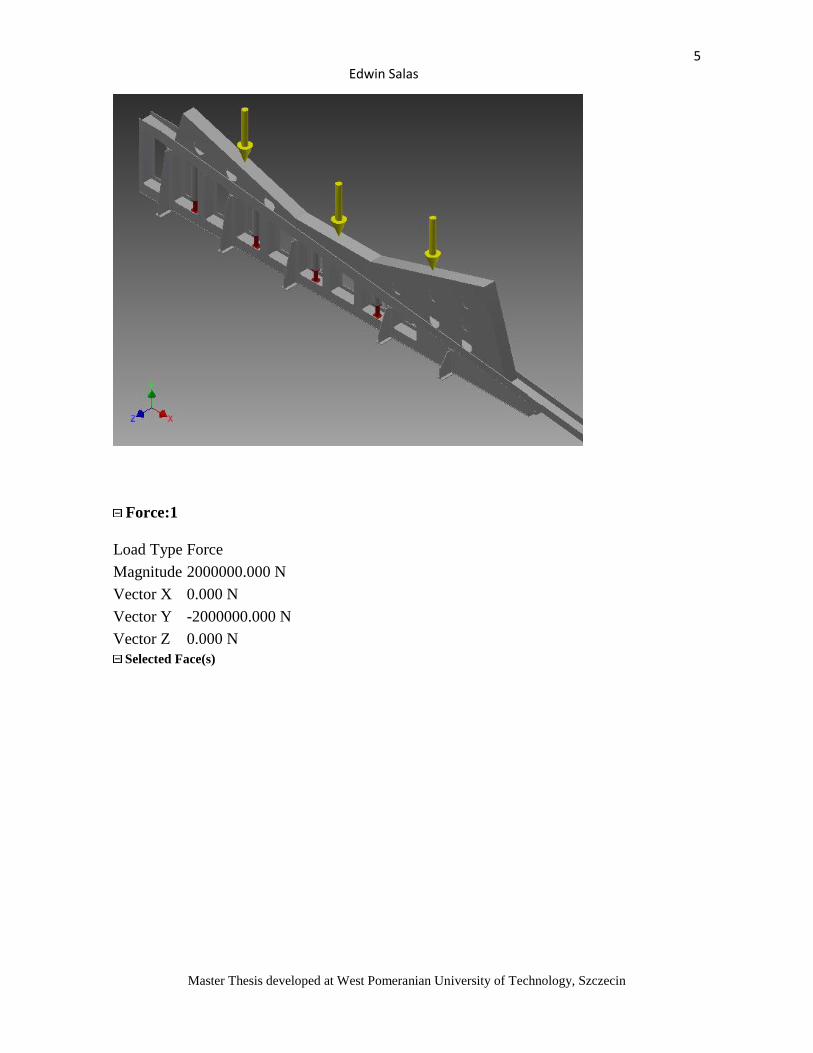
5 Edwin Salas
Master Thesis developed at West Pomeranian University of Technology, Szczecin
Force:1
Load Type Force
Magnitude 2000000.000 N
Vector X 0.000 N
Vector Y -2000000.000 N
Vector Z 0.000 N
Selected Face(s)

6
“EMSHIP” Erasmus Mundus Master Course, period of study September 2015 – February 2017
Fixed Constraint:1
Constraint Type Fixed Constraint
Selected Face(s)

7 Edwin Salas
Master Thesis developed at West Pomeranian University of Technology, Szczecin
Contacts (Bonded)
Name Part Name(s)
Bonded:1 Slip2a- 1000t:1
jack2:1
Bonded:2 Slip2a- 1000t:1
jack2:2
Bonded:3 Slip2a- 1000t:1
jack2:3
Bonded:4 Slip2a- 1000t:1
jack2:4
Bonded:5 Slip2a- 1000t:1
jack2:5
Bonded:6 Slip2a- 1000t:1
jack1:1
Bonded:7 Slip2a- 1000t:1
jack1:2
Bonded:8 Slip2a- 1000t:1
jack1:3
Bonded:9 Slip2a- 1000t:1
jack1:4
Bonded:10 Slip2a- 1000t:1
jack1:5
Bonded:11 Slip2a- 1000t:1
Assembly total reforce-1000t:1/Slip5- 1000t:1
Bonded:12 Slip2a- 1000t:1
Assembly total reforce-1000t:1/reforce 900-1000t:1
Bonded:13 Slip2a- 1000t:1
Assembly total reforce-1000t:1/reforce 1200-1000t:1
Bonded:14 Slip2a- 1000t:1
Assembly total reforce-1000t:1/reforce 1700-1000t:1
Bonded:15 Slip2a- 1000t:1
Assembly total reforce-1000t:1/reforce 2000-1000t:1
Bonded:16 Slip2a- 1000t:1
Assembly total reforce-1000t:1/reforce 2400-1000t:1
Bonded:17 Slip2a- 1000t:1
Assembly total reforce-1000t:1/reforce 900-1000t_MIR:1
Bonded:18 Slip2a- 1000t:1
Assembly total reforce-1000t:1/reforce 1200-1000t_MIR:1
Bonded:19 Slip2a- 1000t:1

8
“EMSHIP” Erasmus Mundus Master Course, period of study September 2015 – February 2017
Assembly total reforce-1000t:1/reforce 1700-1000t_MIR:1
Bonded:20 Slip2a- 1000t:1
Assembly total reforce-1000t:1/reforce 2000-1000t_MIR:1
Bonded:21 Slip2a- 1000t:1
Assembly total reforce-1000t:1/reforce 2400-1000t_MIR:1
Bonded:22 Slip2a- 1000t:1
Slip6- 1000t:1
Bonded:23 Slip2a- 1000t:1
Slip6- 1000t:1
Bonded:24 Slip2a- 1000t:1
Slip8- 1000t:1
Bonded:25 jack2:1
jack3:5
Bonded:26 jack2:2
jack3:4
Bonded:27 jack2:3
jack3:3
Bonded:28 jack2:4
jack3:2
Bonded:29 jack2:5
jack3:1
Bonded:30 jack3:1
jack1:1
Bonded:31 jack3:1
Assembly total reforce-1000t:1/Slip5- 1000t:1
Bonded:32 jack3:2
jack1:2
Bonded:33 jack3:2
Assembly total reforce-1000t:1/Slip5- 1000t:1
Bonded:34 jack3:3
jack1:3
Bonded:35 jack3:3
Assembly total reforce-1000t:1/Slip5- 1000t:1
Bonded:36 jack3:4
jack1:4
Bonded:37 jack3:4
Assembly total reforce-1000t:1/Slip5- 1000t:1
Bonded:38 jack3:5
jack1:5
Bonded:39 jack3:5
Assembly total reforce-1000t:1/Slip5- 1000t:1
Bonded:40 jack1:1

9 Edwin Salas
Master Thesis developed at West Pomeranian University of Technology, Szczecin
Assembly total reforce-1000t:1/Slip5- 1000t:1
Bonded:41 jack1:2
Assembly total reforce-1000t:1/Slip5- 1000t:1
Bonded:42 jack1:3
Assembly total reforce-1000t:1/Slip5- 1000t:1
Bonded:43 jack1:4
Assembly total reforce-1000t:1/Slip5- 1000t:1
Bonded:44 jack1:5
Assembly total reforce-1000t:1/Slip5- 1000t:1
Bonded:45 Assembly total reforce-1000t:1/Slip5- 1000t:1
Assembly total reforce-1000t:1/reforce 900-1000t:1
Bonded:46 Assembly total reforce-1000t:1/Slip5- 1000t:1
Assembly total reforce-1000t:1/reforce 1200-1000t:1
Bonded:47 Assembly total reforce-1000t:1/Slip5- 1000t:1
Assembly total reforce-1000t:1/reforce 1700-1000t:1
Bonded:48 Assembly total reforce-1000t:1/Slip5- 1000t:1
Assembly total reforce-1000t:1/reforce 2000-1000t:1
Bonded:49 Assembly total reforce-1000t:1/Slip5- 1000t:1
Assembly total reforce-1000t:1/reforce 2400-1000t:1
Bonded:50 Assembly total reforce-1000t:1/Slip5- 1000t:1
Assembly total reforce-1000t:1/reforce 900-1000t_MIR:1
Bonded:51 Assembly total reforce-1000t:1/Slip5- 1000t:1
Assembly total reforce-1000t:1/reforce 1200-1000t_MIR:1
Bonded:52 Assembly total reforce-1000t:1/Slip5- 1000t:1
Assembly total reforce-1000t:1/reforce 1700-1000t_MIR:1
Bonded:53 Assembly total reforce-1000t:1/Slip5- 1000t:1
Assembly total reforce-1000t:1/reforce 2000-1000t_MIR:1
Bonded:54 Assembly total reforce-1000t:1/Slip5- 1000t:1
Assembly total reforce-1000t:1/reforce 2400-1000t_MIR:1
Bonded:55 Slip6- 1000t:1
Slip8- 1000t:1
Results
Reaction Force and Moment on Constraints
Constraint Name Reaction Force Reaction Moment
Magnitude Component (X,Y,Z) Magnitude Component (X,Y,Z)
Fixed Constraint:1 2376740 N
0 N
88039.1 N m
-13481.4 N m
2376740 N 5814.26 N m
0 N 86806.3 N m
Result Summary

10
“EMSHIP” Erasmus Mundus Master Course, period of study September 2015 – February 2017
Name Minimum Maximum
Volume 4.88333E+009 mm^3
Mass 38431.8 kg
Von Mises Stress 0.000127746 MPa 35.511 MPa
1st Principal Stress -11.2895 MPa 26.9597 MPa
3rd Principal Stress -38.94 MPa 11.2896 MPa
Displacement 0 mm 0.501022 mm
Safety Factor 9.8561 ul 15 ul
Stress XX -25.0564 MPa 26.9385 MPa
Stress XY -17.4477 MPa 10.489 MPa
Stress XZ -7.15971 MPa 6.39185 MPa
Stress YY -35.9186 MPa 18.4263 MPa
Stress YZ -7.79221 MPa 7.46792 MPa
Stress ZZ -23.4107 MPa 22.2479 MPa
X Displacement -0.103894 mm 0.166469 mm
Y Displacement -0.470682 mm 0.0214209 mm
Z Displacement -0.384363 mm 0.411148 mm
Equivalent Strain 0.000000000610644 ul 0.000157544 ul
1st Principal Strain -0.00000737953 ul 0.000122994 ul
3rd Principal Strain -0.00018007 ul 0.0000110102 ul
Strain XX -0.000124006 ul 0.00011658 ul
Strain XY -0.000112538 ul 0.0000676538 ul
Strain XZ -0.0000461801 ul 0.0000412274 ul
Strain YY -0.000169518 ul 0.0000863414 ul
Strain YZ -0.0000502598 ul 0.0000481681 ul
Strain ZZ -0.000109102 ul 0.000094241 ul
Contact Pressure 0 MPa 53.4107 MPa
Contact Pressure X -9.96378 MPa 9.94806 MPa
Contact Pressure Y -52.1738 MPa 26.2587 MPa
Contact Pressure Z -18.1258 MPa 17.1508 MPa
Figures
Von Mises Stress

11 Edwin Salas
Master Thesis developed at West Pomeranian University of Technology, Szczecin
1st Principal Stress

12
“EMSHIP” Erasmus Mundus Master Course, period of study September 2015 – February 2017
3rd Principal Stress
Displacement

13 Edwin Salas
Master Thesis developed at West Pomeranian University of Technology, Szczecin
Safety Factor
Stress XX

14
“EMSHIP” Erasmus Mundus Master Course, period of study September 2015 – February 2017
Stress XY
Stress XZ

15 Edwin Salas
Master Thesis developed at West Pomeranian University of Technology, Szczecin
Stress YY
Stress YZ

16
“EMSHIP” Erasmus Mundus Master Course, period of study September 2015 – February 2017
Stress ZZ
X Displacement

17 Edwin Salas
Master Thesis developed at West Pomeranian University of Technology, Szczecin
Y Displacement
Z Displacement

18
“EMSHIP” Erasmus Mundus Master Course, period of study September 2015 – February 2017
Equivalent Strain

19 Edwin Salas
Master Thesis developed at West Pomeranian University of Technology, Szczecin
1st Principal Strain
3rd Principal Strain

20
“EMSHIP” Erasmus Mundus Master Course, period of study September 2015 – February 2017
Strain XX
Strain XY

21 Edwin Salas
Master Thesis developed at West Pomeranian University of Technology, Szczecin
Strain XZ
Strain YY
Strain YZ

22
“EMSHIP” Erasmus Mundus Master Course, period of study September 2015 – February 2017
Strain ZZ

23 Edwin Salas
Master Thesis developed at West Pomeranian University of Technology, Szczecin
Contact Pressure
Contact Pressure X
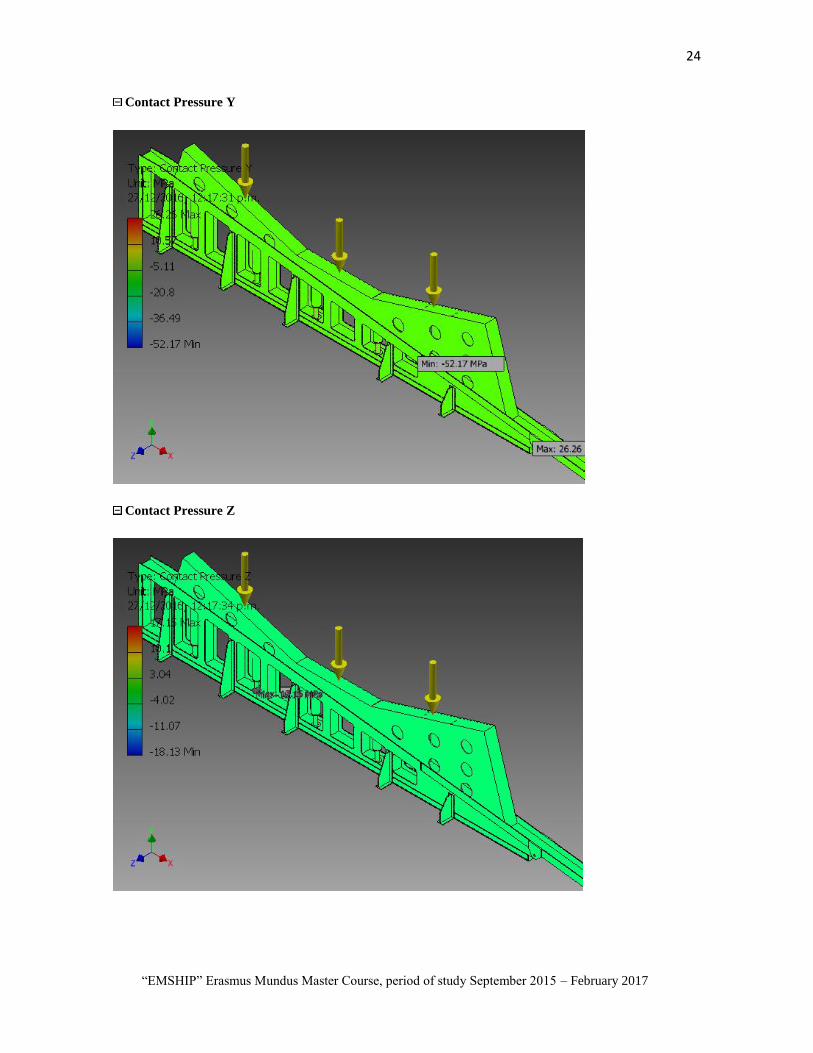
24
“EMSHIP” Erasmus Mundus Master Course, period of study September 2015 – February 2017
Contact Pressure Y
Contact Pressure Z

1 Edwin Salas
Master Thesis developed at West Pomeranian University of Technology, Szczecin
ANNEX 3 Autodesk® Inventor® - Stress Analysis of Portable slipway in down position

2
“EMSHIP” Erasmus Mundus Master Course, period of study September 2015 – February 2017
Stress Analysis Report-200tn-In Down
Position
Analyzed File: Assembly not jacks.iam
Autodesk Inventor Version: 2013 (Build 000000000, 000)
Creation Date: 00/00/2016, 02:05 p.m.
Simulation Author: Edwin Salas
Summary:
Project Info (iProperties)
Summary
Author usuario
Project
Part Number Assembly not jacks
Designer Edwin Salas
Cost S/. 0.00
Date Created 00/00/2016
Status
Design Status WorkInProgress
Physical
Mass 30296.9 kg
Area 257646000 mm^2
Volume 3.84967E+009 mm^3
Center of Gravity
x=1309.09 mm
y=-194.587 mm
z=272.5 mm
Note: Physical values could be different from Physical values used by FEA reported below.
Simulation:not jacks 200tn

3 Edwin Salas
Master Thesis developed at West Pomeranian University of Technology, Szczecin
General objective and settings:
Design Objective Single Point
Simulation Type Static Analysis
Last Modification Date 28/12/2016, 11:39 a.m.
Detect and Eliminate Rigid Body Modes No
Separate Stresses Across Contact Surfaces No
Motion Loads Analysis No
Mesh settings:
Avg. Element Size (fraction of model diameter) 0.05
Min. Element Size (fraction of avg. size) 0.1
Grading Factor 1.5
Max. Turn Angle 20 deg
Create Curved Mesh Elements No
Use part based measure for Assembly mesh Yes
Material(s)
Name Steel, Carbon
General
Mass Density 7.87 g/cm^3
Yield Strength 350 MPa
Ultimate Tensile Strength 420 MPa
Stress
Young's Modulus 200 GPa
Poisson's Ratio 0.29 ul
Shear Modulus 77.5194 GPa
Stress Thermal
Expansion Coefficient 0.000012 ul/c
Thermal Conductivity 52 W/( m K )
Specific Heat 486 J/( kg c )
Part Name(s)
Slip2a- 1000t
Slip8- 1000t
Slip6- 1000t
Operating conditions
Gravity
Load Type Gravity
Magnitude 9810.000 mm/s^2
Vector X -0.000 mm/s^2

4
“EMSHIP” Erasmus Mundus Master Course, period of study September 2015 – February 2017
Vector Y -9810.000 mm/s^2
Vector Z 0.000 mm/s^2
Selected Face(s)
Force:1
Load Type Force
Magnitude 2000000.000 N
Vector X 0.000 N
Vector Y -2000000.000 N
Vector Z 0.000 N
Selected Face(s)

5 Edwin Salas
Master Thesis developed at West Pomeranian University of Technology, Szczecin
Fixed Constraint:1
Constraint Type Fixed Constraint
Selected Face(s)

6
“EMSHIP” Erasmus Mundus Master Course, period of study September 2015 – February 2017
Contacts (Bonded)
Name Part Name(s)
Bonded:1 Slip2a- 1000t:1
Slip8- 1000t:1
Bonded:2 Slip2a- 1000t:1
Slip6- 1000t:1
Bonded:3 Slip2a- 1000t:1
Slip6- 1000t:1
Bonded:4 Slip8- 1000t:1
Slip6- 1000t:1
Results
Reaction Force and Moment on Constraints
Constraint Name Reaction Force Reaction Moment
Magnitude Component (X,Y,Z) Magnitude Component (X,Y,Z)
Fixed Constraint:1 2296990 N
0 N
1862200 N m
-5565.01 N m
2296990 N 0 N m
0 N 1862190 N m
Result Summary
Name Minimum Maximum
Volume 3.84969E+009 mm^3
Mass 30297.1 kg
Von Mises Stress 0.00415836 MPa 83.9967 MPa
1st Principal Stress -20.3477 MPa 66.4897 MPa
3rd Principal Stress -92.9984 MPa 15.3145 MPa
Displacement 0 mm 1.16991 mm
Safety Factor 4.16683 ul 15 ul
Stress XX -33.6684 MPa 38.7242 MPa
Stress XY -24.3822 MPa 36.1893 MPa
Stress XZ -11.1489 MPa 11.0752 MPa
Stress YY -89.8278 MPa 49.1474 MPa
Stress YZ -35.8343 MPa 26.1145 MPa
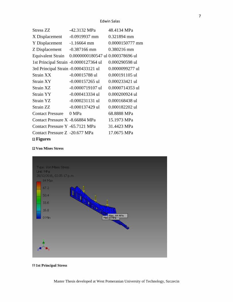
7 Edwin Salas
Master Thesis developed at West Pomeranian University of Technology, Szczecin
Stress ZZ -42.3132 MPa 48.4134 MPa
X Displacement -0.0919937 mm 0.321894 mm
Y Displacement -1.16664 mm 0.0000150777 mm
Z Displacement -0.387166 mm 0.380216 mm
Equivalent Strain 0.0000000180547 ul 0.000378696 ul
1st Principal Strain -0.0000127364 ul 0.000290598 ul
3rd Principal Strain -0.000433121 ul 0.0000099277 ul
Strain XX -0.00015788 ul 0.000191105 ul
Strain XY -0.000157265 ul 0.000233421 ul
Strain XZ -0.0000719107 ul 0.0000714353 ul
Strain YY -0.000413334 ul 0.000200924 ul
Strain YZ -0.000231131 ul 0.000168438 ul
Strain ZZ -0.000137429 ul 0.000182202 ul
Contact Pressure 0 MPa 68.8888 MPa
Contact Pressure X -8.66884 MPa 15.1973 MPa
Contact Pressure Y -65.7121 MPa 31.4423 MPa
Contact Pressure Z -20.677 MPa 17.0675 MPa
Figures
Von Mises Stress
1st Principal Stress

8
“EMSHIP” Erasmus Mundus Master Course, period of study September 2015 – February 2017
3rd Principal Stress
Displacement

9 Edwin Salas
Master Thesis developed at West Pomeranian University of Technology, Szczecin
Safety Factor
Stress XX

10
“EMSHIP” Erasmus Mundus Master Course, period of study September 2015 – February 2017
Stress XY

11 Edwin Salas
Master Thesis developed at West Pomeranian University of Technology, Szczecin
Stress XZ
Stress YY

12
“EMSHIP” Erasmus Mundus Master Course, period of study September 2015 – February 2017
Stress YZ
Stress ZZ
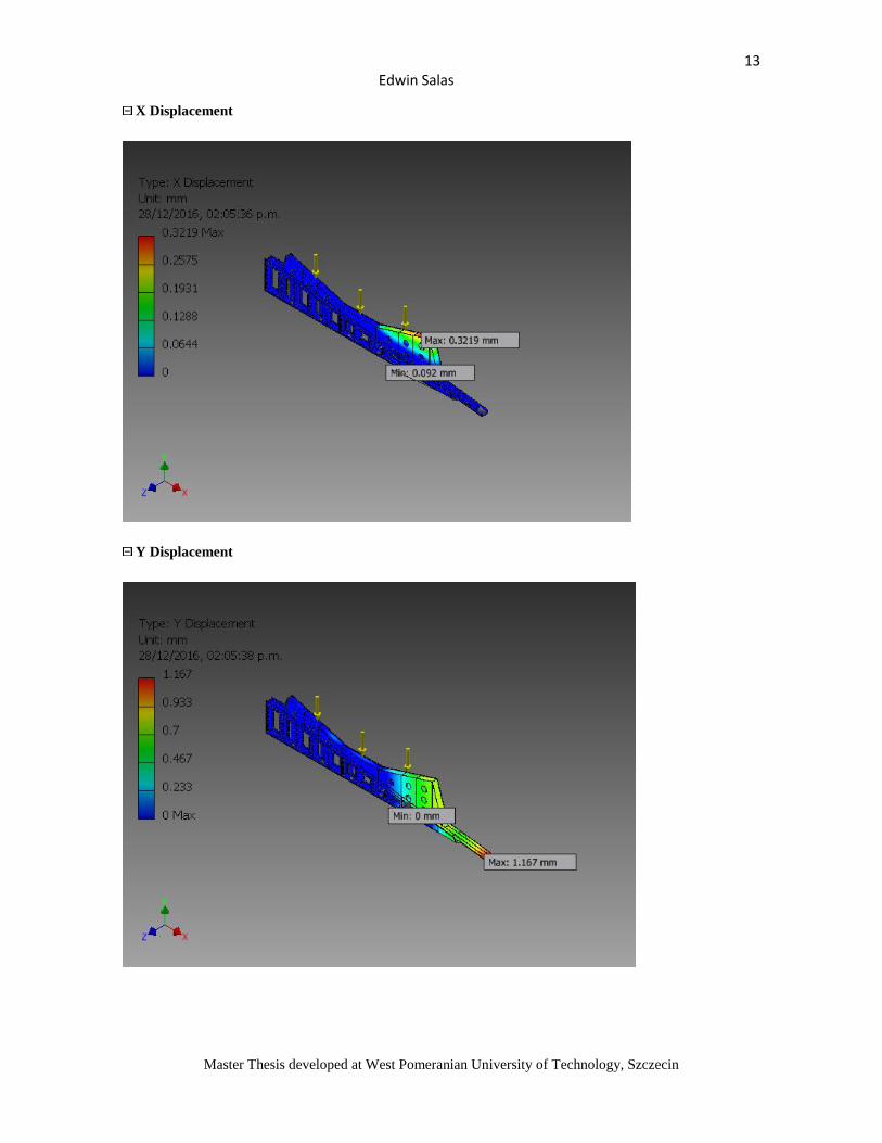
13 Edwin Salas
Master Thesis developed at West Pomeranian University of Technology, Szczecin
X Displacement
Y Displacement

14
“EMSHIP” Erasmus Mundus Master Course, period of study September 2015 – February 2017
Z Displacement
Equivalent Strain

15 Edwin Salas
Master Thesis developed at West Pomeranian University of Technology, Szczecin
1st Principal Strain
3rd Principal Strain

16
“EMSHIP” Erasmus Mundus Master Course, period of study September 2015 – February 2017
Strain XX
Strain XY

17 Edwin Salas
Master Thesis developed at West Pomeranian University of Technology, Szczecin
Strain XZ
Strain YY

18
“EMSHIP” Erasmus Mundus Master Course, period of study September 2015 – February 2017
Strain YZ
Strain ZZ

19 Edwin Salas
Master Thesis developed at West Pomeranian University of Technology, Szczecin
Contact Pressure

20
“EMSHIP” Erasmus Mundus Master Course, period of study September 2015 – February 2017
Contact Pressure X
Contact Pressure Y

21 Edwin Salas
Master Thesis developed at West Pomeranian University of Technology, Szczecin
Contact Pressure Z


1 Edwin Salas
Master Thesis developed at West Pomeranian University of Technology, Szczecin
ANNEX 4 Plans of Portable slipway

2
“EMSHIP” Erasmus Mundus Master Course, period of study September 2015 – February 2017

3 Edwin Salas
Master Thesis developed at West Pomeranian University of Technology, Szczecin

4
“EMSHIP” Erasmus Mundus Master Course, period of study September 2015 – February 2017

5 Edwin Salas
Master Thesis developed at West Pomeranian University of Technology, Szczecin

6
“EMSHIP” Erasmus Mundus Master Course, period of study September 2015 – February 2017

7 Edwin Salas
Master Thesis developed at West Pomeranian University of Technology, Szczecin