Embed Size (px)
Citation preview

RULES FORCLASSIFICATION OF
SHIPS / HIGH SPEED, LIGHT CRAFT ANDNAVAL SURFACE CRAFT
NEWBUILDINGS
MACHINERY AND SYSTEMSMAIN CLASS
PART 4 CHAPTER 8
ELECTRICAL INSTALLATIONSJANUARY 2003
CONTENTS PAGE
Sec. 1 Service Description .................................................................................................................... 7Sec. 2 System Design .......................................................................................................................... 13Sec. 3 Equipment in General............................................................................................................... 36Sec. 4 Switchgear and Controlgear Assemblies.................................................................................. 42Sec. 5 Rotating Machines.................................................................................................................... 48Sec. 6 Power Transformers ................................................................................................................. 53Sec. 7 Semi-conductor Converters ...................................................................................................... 55Sec. 8 Miscellaneous Equipment ........................................................................................................ 57Sec. 9 Cables ....................................................................................................................................... 60Sec. 10 Installation ................................................................................................................................ 63Sec. 11 Hazardous Areas Installations .................................................................................................. 74Sec. 12 Electric Propulsion ................................................................................................................... 78Sec. 13 Definitions ................................................................................................................................ 82
This is a re-print with the relevant amendments and corrections, shown in the current Pt.0 Ch.1 Sec.3, inserted into the body of the text.
DET NORSKE VERITAS
Veritasveien 1, N-1322 Høvik, Norway Tel.: +47 67 57 99 00 Fax: +47 67 57 99 11

CHANGES IN THE RULES
General
The present edition of the rules includes additions and amendmentsdecided by the Board as of December 2002, and supersedes the Janu-ary 2001 edition of the same chapter.
The rule changes come into force on 1 July 2003.
This chapter is valid until superseded by a revised chapter. Supple-ments will not be issued except for an updated list of minor amend-ments and corrections presented in Pt.0 Ch.1 Sec.3. Pt.0 Ch.1 isnormally revised in January and July each year.
Revised chapters will be forwarded to all subscribers to the rules.Buyers of reprints are advised to check the updated list of rule chap-ters printed Pt.0 Ch.1 Sec.1 to ensure that the chapter is current.
Main changes
• Sec.1 Service Description
General: references to SOLAS Reg. II-1 have been added.
— Table B1, concerning load balance, has been amended.— In item B303 a new item f), concerning case by case approval has
been added.
• Sec.2 System Design
— In item A103 a new item f), concerning earthing of aluminiumsuperstructures, has been added.
— In item C103 a new item f), concerning services to be suppliedfor fishing vessels, has been added.
— Table C1, concerning class notations NAUT-AW and NAUT-OC, have been added.
— In item C104 the requirements for main sources of electricalpower have been clarified.
— In item C105 a new item i), concerning cables in the emergencygenerator room, has been added.
— In item E101 a new item e), concerning shaft generator installa-tions, has been added.
— In item E103 a new item d), concerning High Speed and LightCraft category B, has been added.
— In item G102 a new item e), concerning direct-earthed system,has been added.
— Item G103c), concerning a new requirement for isolating switch-es, has been amended.
— The list in H101a), concerning oil pumps, has been amended.— Previous item I103 has been amended to read sub-section I200
“Switchboard arrangement”. — Sub-section element I200 has been renumbered and renamed to
read: I300 “Rotating machines”.— A new sub-item c), concerning installation of pipes above gener-
ators, has been added to renumbered item I301.— Sub-section element I300 “Battery installations” has been re-
numbered to read I400.— Sub-section element I400 “Cable routing” has been renumbered
to read I500.— Sub-item c, concerning the protection and routing of main cable
runs, has been deleted from renumbered item I501.— In renumbered item I502 item a), concerning cable routing in
case of fire, has been deleted.— Sub-section element I500 “Lightning protection” has been re-
numbered to read I600.— A new sub-section I700 “Earthing of aluminium superstructures
on steel vessels” has been added.— Item J102 “Fire resistant cables” has been completely rewritten.
• Sec.3 Equipment in General
— In item D603 item a), concerning minimum clearance distance,has been expanded.
— A new Table D3 “Alternative impulse voltage test” has been in-cluded.
— In Table F1 a new insulation class E has been added.
• Sec.4 Switchgear and Controlgear assemblies
— Two new items, B105 “rating of copper bus bars” and B106 “rat-ing of aluminium bus bars” have been added.
— In renumbered item B107 a new sub-item g), concerning circuitbreakers rated more than 16A, has been added.
— Renumbered item B108b), concerning arrangement of switch-gear, has been amended.
— Item B301d), concerning switchgear, has been clarified.— Sub-section D has been renamed “Inspection and Testing”.
• Sec.5 Rotating Machines
— In item A203 a new item h), concerning machines with insulatingclass 220, has been added.
• Sec.6 Power Transformers
— In item A202 sub-item a), concerning transformers filled withliquid with flashpoint above 60°C, has been added.
— Item A208, concerning enclosure requirement, has been deleted. — In item B101b) a new sub-item, concerning lighting impulse
withstand test, has been added.— A new item B104 “Lightning impulse withstand testing” has
been added. — A new Table B1 “Test voltages” has been added.
• Sec.7 Semi-conductor Converters
— Sub-section B100 has been renamed “General”.— Item B101 has been renamed “Factory Testing”.
• Sec.8 Miscellaneous Equipment
— Item A408 has been deleted. The content is considered coveredin Sec.10 C1000.
• Sec.9 Cables
— The item A101b), concerning requirements for flexible cables,has been deleted.
— A new item A101c), concerning flame-retardant type cables, hasbeen introduced.
— A new sub-section G “Fibre Optic cables” has been added.
• Sec.10 Installation
— A new sub-section B600 “Neon lighting” has been added.— A new item C406, concerning fire resistance cable, has been add-
ed.— A new item C502d), concerning load on cable trays, has been
added.— A new item C502e), concerning cable trays or protective casings
made of plastic materials, has been added.— Item C505a), concerning fixing of cables by non-metallic clips or
straps, has been amended.— A new item C505b), concerning flame retardant polymer materi-
al, has been added.— Items C506 and C507 have been deleted.— Item C904g) has been expanded to include connecting braiding
or armour directly to dedicated earth terminal or bar.
Comments to the rules may be sent by e-mail to [email protected] subscription orders or information about subscription terms, please use [email protected] information about DNV and the Society's services is found at the Web site http://www.dnv.com
© Det Norske VeritasComputer Typesetting (FM+SGML) by Det Norske Veritas Printed in Norway
If any person suffers loss or damage which is proved to have been caused by any negligent act or omission of Det Norske Veritas, then Det Norske Veritas shall pay compensation to such personfor his proved direct loss or damage. However, the compensation shall not exceed an amount equal to ten times the fee charged for the service in question, provided that the maximum compen-sation shall never exceed USD 2 million.In this provision "Det Norske Veritas" shall mean the Foundation Det Norske Veritas as well as all its subsidiaries, directors, officers, employees, agents and any other acting on behalf of DetNorske Veritas.

Rules for Ships / High Speed, Light Craft and Naval Surface Craft, January 2003Pt.4 Ch.8 – Page 3
• Sec.11 Hazardous Areas - Installations
— In item C101, sub-item c, concerning installations covered by therules, has been moved and renumbered to A101c).
— Item D200 has been renamed “Cabling and termination”.— Item D206 has been made more specific concerning design and
the insulation of the conductors.
Corrections and Clarifications
In addition to the above stated rule requirements, a number of detectederrors, corrections and clarifications have been made in the existingrule text.
DET NORSKE VERITAS

Rules for Ships / High Speed, Light Craft and Naval Surface Craft, January 2003Pt.4 Ch.8 Contents – Page 4
CONTENTS
SEC. 1 SERVICE DESCRIPTION ................................. 7
A. Application ............................................................................ 7A 100 General ..............................................................................7
B. Verification Scheme.............................................................. 7B 100 General ..............................................................................7B 200 System design ...................................................................8B 300 Equipment certification.....................................................9B 400 Site survey.......................................................................12
SEC. 2 SYSTEM DESIGN ............................................. 13
A. Power Supply Systems........................................................ 13A 100 General ............................................................................13A 200 System voltages and frequency.......................................14
B. Main Electric Power Supply System................................. 15B 100 General ............................................................................15
C. Emergency Power Supply System..................................... 16C 100 Emergency power and distribution ................................16C 200 Transitional source ..........................................................20C 300 Emergency generators.....................................................20
D. Battery Installation............................................................. 21D 100 General ............................................................................21
E. Generator Prime Movers ................................................... 21E 100 General ...........................................................................21
F. Electric Power Distribution ............................................... 22F 100 Distribution in general ....................................................22F 200 Lighting...........................................................................23F 300 Shore connections ...........................................................23
G. Protection ............................................................................ 24G 100 System protection............................................................24G 200 Circuit protection ............................................................24G 300 Generator protection .......................................................26G 400 Transformer protection ...................................................26G 500 Motor protection .............................................................26
H. Control................................................................................. 27H 100 System control.................................................................27H 200 Motor control ..................................................................28
I. Vessel Arrangement ........................................................... 28I 100 General ............................................................................28I 200 Switchboard arrangement ...............................................29I 300 Rotating machines...........................................................30I 400 Battery installations.........................................................30I 500 Cable routing...................................................................31I 600 Lightning protection........................................................31I 700 Earthing of aluminium superstructures on steel vessels .32
J. Cable Selection.................................................................... 32J 100 General ............................................................................32J 200 Cable temperature ...........................................................32J 300 Choice of insulating materials.........................................32J 400 Current rating ..................................................................33J 500 Correction factors............................................................33J 600 Parallel connection of cables...........................................34J 700 Additional requirements for A.C. installations, and
special D.C. installations.................................................34J 800 Rating of cables...............................................................34
SEC. 3 EQUIPMENT IN GENERAL ........................... 36
A. General Requirements ....................................................... 36A 100 References .......................................................................36
B. Environmental Requirements ........................................... 36B 100 Inclinations......................................................................36B 200 Vibrations and accelerations ...........................................36B 300 Temperature and humidity ..............................................36
C. Equipment Ratings .............................................................37C 100 Electrical parameters.......................................................37C 200 Maximum operating temperatures ..................................37
D. Mechanical and Electrical Properties ...............................37D 100 Mechanical strength ........................................................37D 200 Cooling and anti-condensation........................................38D 300 Termination and cable entrances.....................................38D 400 Equipment protective earthing ........................................38D 500 Enclosures ingress protection..........................................39D 600 Clearance and creepage distances ...................................39
E. Marking and Signboards ...................................................40E 100 General ............................................................................40
F. Insulation .............................................................................40F 100 Insulation materials .........................................................40
SEC. 4 SWITCHGEAR AND CONTROLGEAR ASSEMBLIES..................................................... 42
A. Construction........................................................................42A 100 General ............................................................................42
B. Power Circuits.....................................................................43B 100 Power components in assemblies....................................43B 200 Batteries ..........................................................................44B 300 Additional requirements for high voltage assemblies.....45
C. Control and Protection Circuits ........................................45C 100 Control and instrumentation............................................45
D. Inspection and Testing .......................................................46D 100 General ............................................................................46
SEC. 5 ROTATING MACHINES................................. 48
A. General.................................................................................48A 100 References.......................................................................48A 200 Requirements common to generators and motors...........48A 300 Instrumentation of machines...........................................49
B. Additional Requirements for Generators.........................49B 100 General ............................................................................49B 200 Voltage and frequency regulation ...................................49B 300 Generator short circuit capabilities .................................50B 400 Parallel operation ............................................................50
C. Inspection and Testing .......................................................51C 100 General ............................................................................51
SEC. 6 POWER TRANSFORMERS............................ 53
A. General.................................................................................53A 100 General ............................................................................53A 200 Design requirements for power transformers..................53
B. Inspection and Testing .......................................................53B 100 General ............................................................................53
SEC. 7 SEMI-CONDUCTOR CONVERTERS ........... 55
A. General Requirements........................................................55A 100 General ............................................................................55A 200 Mechanical requirements ................................................55A 300 Design requirements, electrical, for semi-conductor
assemblies .......................................................................55
B. Inspection and Testing .......................................................55B 100 General ............................................................................55
SEC. 8 MISCELLANEOUS EQUIPMENT................. 57
A. General.................................................................................57A 100 Battery boxes and lockers ...............................................57A 200 Socket outlets and plugs..................................................57A 300 Lighting equipment .........................................................57
DET NORSKE VERITAS

Rules for Ships / High Speed, Light Craft and Naval Surface Craft, January 2003 Pt.4 Ch.8 Contents – Page 5
A 400 Heating equipment .........................................................58A 500 Cooking and other galley equipment .............................59
SEC. 9 CABLES.............................................................. 60
A. Application...........................................................................60A 100 General ............................................................................60
B. General Cable Construction ..............................................60B 100 General ............................................................................60
C. High Voltage Cables............................................................60C 100 General ............................................................................60
D. Low Voltage Power Cables.................................................61D 100 Cables rated 0.6/1 kV and 1.8/3 kV................................61D 200 Protective sheaths............................................................61D 300 Wire braid and armour ....................................................62D 400 Switchboard wires...........................................................62D 500 Lightweight electrical cables ..........................................62
E. Control Cables.....................................................................62E 100 Construction ....................................................................62
F. Instrumentation and Communication Cables ..................62F 100 General ............................................................................62
G. Fiber Optic Cables ..............................................................62G 100 General ............................................................................62
SEC. 10 INSTALLATION ............................................... 63
A. General Requirements........................................................63A 100 General ............................................................................63
B. Equipment............................................................................63B 100 Equipment location and arrangement .............................63B 200 Equipment enclosure, Ingress Protection........................63B 300 Batteries ..........................................................................65B 400 Protective earthing and bonding of equipment ...............65B 500 Equipment termination, disconnection, marking ............66B 600 Neon lighting ..................................................................66
C. Cables ...................................................................................66C 100 General ............................................................................66C 200 Routing of cables ............................................................67C 300 Penetrations of bulkhead and decks ................................67C 400 Fire protection measures .................................................67C 500 Support and fixing of cables and cable runs ...................68C 600 Cable expansion ..............................................................69C 700 Cable pipes......................................................................70C 800 Splicing of cables ............................................................70C 900 Termination of cables......................................................70C 1000 Trace or surface heating installation requirements .........71
D. Inspection and Testing....................................................... 71D 100 General ............................................................................71D 200 Equipment installation ....................................................72D 300 Wiring and earthing ........................................................72D 400 Distribution system properties ........................................72
SEC. 11 HAZARDOUS AREAS INSTALLATIONS.... 74
A. General ................................................................................ 74A 100 General ............................................................................74
B. Documentation.................................................................... 74B 100 General ............................................................................74
C. Equipment Selection .......................................................... 74C 100 General ............................................................................74C 200 Ex protection according to zones....................................74C 300 Additional requirements for equipment and circuit
design ..............................................................................75
D. Installation Requirements ................................................. 75D 100 General ............................................................................75D 200 Cabling and termination..................................................76
SEC. 12 ELECTRIC PROPULSION ............................. 78
A. General ................................................................................ 78A 100 General ............................................................................78A 200 System design .................................................................78A 300 System capacity ..............................................................78A 400 Electric supply system ....................................................78A 500 System protection............................................................79A 600 Control systems...............................................................79
B. Torsional Vibrations .......................................................... 80B 100 General ............................................................................80B 200 Vibration measurements .................................................80B 300 Steady state - torsional vibration.....................................80B 400 Transient torsional vibration ...........................................80
C. Verification ......................................................................... 81C 100 Factory testing or manufacturer’s testing .......................81
SEC. 13 DEFINITIONS ................................................... 82
A. Definitions ........................................................................... 82A 100 General ............................................................................82A 200 Operational conditions ....................................................82A 300 Services ...........................................................................82A 400 Installation.......................................................................83A 500 Area definitions...............................................................83A 600 Hazardous area................................................................83A 700 Sources of power, generating station and distribution....84A 800 Switchboard definitions ..................................................84A 900 Components and related expressions ..............................85
DET NORSKE VERITAS

Rules for Ships / High Speed, Light Craft and Naval Surface Craft, January 2003Pt.4 Ch.8 Contents – Page 6
DET NORSKE VERITAS

Rules for Ships / High Speed, Light Craft and Naval Surface Craft, January 2003 Pt.4 Ch.8 Sec.1 – Page 7
SECTION 1SERVICE DESCRIPTION
A. Application
A 100 General
101 Purpose
a) The rules in this chapter apply to electrical installations forassignment of main class.
b) The rules give requirements for all electrical installationswith respect to safety for personnel and fire hazard.
c) The rules give requirements for all electrical installationsserving essential or important services with respect toavailability.
d) The rules give requirements for equipment certification,see B303.
e) For installations of less than 100 kVA total power capaci-ty, the Society may consider modified requirements forboth technical requirements and the verification process.Modified requirements shall be agreed in each case andwill be based on the following information:
— applicable class notations— intended operation— general information on system design.
Information on modified requirements will be made avail-able for the operational phase.
f) Portable electric appliances are not covered by the scopeof classification.
102 Supplementary requirements
Supplementary requirements will be enforced for vessels withadditional class notations, as required by the respective parts ofthe rules.
103 IEC standards
a) The requirements in this chapter are generally based onapplicable standards for ships and offshore units as issuedby IEC (the International Electrotechnical Commission).
b) Where direct reference is made to such standards, it ismeant the standard(s) in force at the time of request forclassification.
c) If the standard has been replaced less than 6 months priorto the date of request for classification, the preceding edi-tion will be accepted.
Guidance note:This implies primarily the IEC 60092 series for ships, and IEC61892 (1 to 7) for offshore units.
---e-n-d---of---G-u-i-d-a-n-c-e---n-o-t-e---
104 Other standards
a) The Society will consider the use of alternative standardsif they are found to represent an overall safety conceptequivalent to that of the rules.
b) Acceptance of the use of other standards may be givenwithout yard’s or owner's or operator’s consent. An appli-cation for acceptance of other standards shall be submit-ted. Upon request, a copy of an English version of thestandard shall be submitted.
105 Alternative solutions
a) Alternative solutions to the requirements in the rules willbe accepted by the Society when found to represent thesame level of safety and availability as the solutions re-quired by these rules. Such an acceptance may be givenwithout yard's, owner's or operator's consent.
b) Verification additional to that required by the rules may benecessary when alternative solutions are proposed.
Guidance note:Special care should be taken when requirements from differentstandards are used within the same system.
---e-n-d---of---G-u-i-d-a-n-c-e---n-o-t-e---
B. Verification Scheme
B 100 General
101 Work processes
a) As a basis for assignment of class, the Society will verifythat the electrical installation complies with the relevantrule requirements. This verification process is organised asfollows:
— approval of system design (200)— equipment certification (300)— site survey (400).
b) The verification process is carried out on a spot check ba-sis. The full responsibility for compliance with the appli-cable rules lies with the yard or any other contractuallybound party.
c) The rules include the approval of standard designs for:
— systems (including distribution systems)— equipment— components.
The assessment of standard designs and subsequent ap-proval, is covered by the type approval scheme.
102 Plan approval
a) Approval of design is based on an assessment of relevantinformation elements.
b) Information elements shall be submitted for assessment asrequired by 200 and 300. The tables include two columnsmarked "Rule verification reference" and "Purpose".
— “Rule verification reference”: Gives reference to rele-vant parts of the rules and indicates the scope of theverification process.
— “Purpose”: Indicates whether the document is to beapproved, used for information only or shall be avail-able for the Society upon request.
c) Elements marked available are considered necessary forthe design and shall be prepared by the responsible party.They will not be subject to assessment unless especiallyrequested by the Society.
— The Society may, when found necessary, require in-formation additional to that listed in the rules.
DET NORSKE VERITAS

Rules for Ships / High Speed, Light Craft and Naval Surface Craft, January 2003Pt.4 Ch.8 Sec.1 – Page 8
B 200 System design201 General
The electrical system design is to be assessed on the basis ofthe information as required by 202 and 203.
202 System philosophy
A “System philosophy” or a description of the overall electri-cal system, shall be submitted for vessels where the “Overallsingle line diagram” is not sufficient to give the necessary un-derstanding of the operation and relevant operation modes ofthe system.
a) A “System philosophy” shall always be submitted for thefollowing vessel types:
— High Speed, Light Craft and Naval Surface Craft— Mobile Offshore Units— Drilling vessels— Oil production and storage units (or related)
— Vessels with bow loading— Passenger vessels— Vessels with electric propulsion systems.
b) The “system philosophy” shall include information on thefollowing - as relevant:
— Configuration of the system in all operating modesand subsequent power distribution philosophy for dif-ferent vessel systems or services (essential, importantand emergency services).
— Functionality of any power management system (in-cluding load shedding, start and stop of power sourc-es, etc.)
— System behaviour in relevant failure modes.— Dead ship recovery arrangement.
203 System information to be submitted
Table B1 System information to be submittedPreferred document Information element Purpose Rule verification refer-
encesSystem philosophy 1) A system philosophy as described in 202. Information Sec.2 A, B, C, D, E, F,
G, HLighting description 2) A lighting philosophy describing normal, emergency, transitional and
battery backed-up lighting for all areas on board.Approval Sec.2 B, C, F200
Cable selection philoso-phy 3)
Criteria for selection with respect to types versus location and voltage levels.
Approval Sec.2 I400, J, Sec.9
Power consumer listing (A.C./D.C.) 4)
Separate listings of power consumers for:
— essential services— important services— emergency services
with information on switchboard connections and any redundancy in technical design or physical arrangement (electrically or otherwise).
Information Sec.13 A300
A.C. power consump-tion balance
Calculated design values for power consumption and available power for relevant operational modes as:
— normal operation— manoeuvring— special operations (e.g. for vessels with class notations POSMOOR,
CRANE, BOW LOADING, Fishing Vessel etc.)— emergency mode
The load balance shall show that the diesel can handle the maximum load connected in one step with a minimum of 1/3 of the diesels rated power. See also Ch.2 Sec.4. Battery charging shall be included on the supply side.Tripping of non-important consumers shall be identified in the calcula-tion.
Approval Sec.2 B, C, D
D.C. power consump-tion balance
Calculated design values for battery capacities for D.C. power supplies and UPS, with relevant operational modes as:
— normal operation— manoeuvring— special operations (e.g. for vessels with class notations POSMOOR,
CRANE, BOW LOADING, Fishing Vessel etc.)— emergency mode
Tripping of non-important consumers shall be identified in the calcula-tion.
Approval Sec.2 B, C, D
Power management sys-tem description
Description of the functionality of any power management system (in-cluding load shedding, start and stop of power sources, etc.).(Automation system for power management is also to be documented and certified as required by Ch.9).
Information Sec.2
DET NORSKE VERITAS

Rules for Ships / High Speed, Light Craft and Naval Surface Craft, January 2003 Pt.4 Ch.8 Sec.1 – Page 9
B 300 Equipment certification301 General
a) All essential equipment and electrical equipment requiredto be certified by 303 shall be documented as described in302.
b) Equipment certification shall be based on a design assess-ment as stated in 201, and a product survey as stated in304.
Overall single line dia-gram
Power system layout with identification of all generators, transformers, switchboards, distribution boards and major consumers.
Approval Sec.2 A, B
System voltages and system earthing. InformationRating of generators (kVA/kW).If a prime mover is also used for driving other machinery, this shall be stated on the overall single line diagram.
Information
Rating of all transformers (kVA) in the distribution system. InformationRatings of any major consumers (kVA/kW). InformationShort circuit levels (peak value and symmetrical root mean square at 0.5 cycle) for all switchboards in the distribution system.For four-wire systems, single pole earth fault currents shall also be noted.
Information
Content of voltage harmonic distortion when more than 20% of connect-ed load is by semi-conductor assemblies, in relation to connected gener-ating capacity. Harmonic distortion should be given for all operating modes of the system.
Information
Upon request, Voltage drop calculation. Both stationary values as well as voltage drop when starting large consumers can be requested (e.g. voltage drop (main switchboard to the motor terminals) when a motor rated above 30% of feeding generator(s) or transformer(s) rated power is started di-rect on line).
Information
Discrimination analysis Discrimination for feeders in the distribution system including list of set-tings of protection for short circuit, overcurrent and earth fault (if rele-vant). The analysis shall include main switchboards, emergency switchboards, and incomers on distribution boards versus largest load.Minimum and maximum short circuit currents, as well as generator dec-rement curves should be stated in the discrimination analysis.
Approval Sec.2 G
Vessel arrangement drawing or block dia-gram also showing loca-tions
Location of main power sources, main switchboards and main distribu-tion boards or emergency power sources, emergency switchboards and emergency distribution boards or transitional source of power, UPSs and batteries.Information on access doors, fire divisions and high fire risk areas related to the above.
Approval Sec.2 A, B, D, F, I, Sec.10
Emergency stop control schematics
Information on emergency stop of fuel oil pumps and ventilation fans showing fail to safe functionality.
Approval Ch.6 Sec.5 A300 (SOLAS Reg. II-2/ 16.1 to 16.11)
Table of Ex-installation Compiled information for all equipment that shall be installed in hazard-ous areas, or areas that may become hazardous by accidental release of explosive gas.The basis for the verification of electrical installations, is an approved Area classification document or drawing or information on installations in battery room or paint stores etc.
Approval Sec.11
1) To be submitted for vessel types or vessels with following systems: HS, LC and NSC, MOU, drilling vessels, oil production and storage units, bow load-ing, passenger ships, electric propulsion systems.
2) To be submitted for vessel types or notations or system: HS, LC and NSC, MOU, drilling vessels, oil production and storage units, bow loading, passenger ships.
3) To be submitted for vessel types or notations HS, LC and NSC, MOU, drilling vessels, oil production and storage units, passenger ships.
4) To be submitted for vessel types or notations or systems: HS, LC and NSC, MOU, drilling vessels, oil production and storage units, passenger ships, elec-tric propulsion systems.
For other vessel types or vessels with other systems, only listing of consumers for essential services are to be submitted.
Table B1 System information to be submitted (Continued)Preferred document Information element Purpose Rule verification refer-
ences
DET NORSKE VERITAS

Rules for Ships / High Speed, Light Craft and Naval Surface Craft, January 2003Pt.4 Ch.8 Sec.1 – Page 10
302 Equipment information to be submitted
Table B2 Cables (when not having a valid type approval certificate)Preferred document Information elements Purpose Rule verification refer-
enceTechnical data sheet and design drawing
— maker— cross sectional drawing— field of application— voltage class root mean square Uo/U— cable type and number of cores - conductor cross-sections (mm²)— number of strands in each conductor— insulation thickness (mm)— sheath thickness inner and outer (mm)— braiding core diameter (mm)— overall diameter (mm)— insulating material— insulating screening— material inner sheath— material outer sheath— material outer braid— documentation of the manufacturers type test results. (Will only be re-
quested from manufacturers without any type approved cables.)— fire test results if relevant
Approval Sec.9
Table B3 Rotating machinesPreferred document Information elements Purpose Rule verification refer-
enceShafting documentation See Ch.4 Sec.1 A200
— For electric propulsion motors and generators in mechanical propulsion line.
Approval Ch.4 Sec.1
Documentation of test results Documentation of results from type tests, if performed. Available Sec.5
Table B4 TransformersPreferred document Information elements Purpose Rule verification refer-
enceDocumentation of test results
Documentation of results from type tests, if performed. Available Sec.6
Table B5 Electrical assemblies: Main and emergency switchboardsPreferred document Information elements Purpose Rule verification refer-
enceElectrical data sheet Design values for environmental parameters. Approval Sec.3 B
Cooling system or ventilation description and design parameters. Information Sec.3 B300, D200IP rating related to intended location onboard. Approval Sec.3 D500Input frequency and voltages. Information Sec.2 A200Designed short circuit strength (peak value and symmetrical root mean square at 0.5 cycle).
Information Sec.2 G
Bus bar strength calcu-lation
Bus bar strength calculation results and corresponding data for bus bars and supports - when designed short circuit strength exceeds 50 kA.
Information Sec.4 A103, B103, B105, B300
Switchboard layout Location of instruments and devices for operation (front panel layout). Information Sec.4 A100Single line diagrams Power cables and bus bar dimensions internal in the equipment. Approval Sec.2 J, Sec.4 B100Switchgear rating doc-ument
Table with switchgear rating for power circuits:
— making and breaking capacity.
Approval Sec.2 G, Sec.4 B100
Functional description A description of normal equipment operation related to normal and abnor-mal system performance (e.g. protection, interlocks, redundancy, trips and shutdowns, other safety actions).
Information Sec.2 A, B, F, G, H
Schematic diagrams Information on protection synchronisation, breaker interlocks, undervolt-age trips, remote control circuits.
Approval Sec.2 G, H
Test program Procedures for routine tests.Procedures for normal equipment operation (ref. functional description) re-lated to normal and abnormal system performance (e.g. protection, inter-locks, redundancy, trips and shutdowns, other safety actions).Shall cover tests planned at the manufacturer’s works as well as tests planned after installation of the assembly onboard.
Approval Sec.2 A, B, C, F, G, H, Sec.4 D
DET NORSKE VERITAS

Rules for Ships / High Speed, Light Craft and Naval Surface Craft, January 2003 Pt.4 Ch.8 Sec.1 – Page 11
303 Required certificates
a) Electrical equipment serving essential or important func-tions and cables shall be delivered with Certificates as re-quired by e).
b) Additional requirements for certification may be given byother relevant parts of the rules.
c) Equipment covered by a valid type approval certificate isgenerally accepted without further design verification, un-less otherwise stated in the certificate. A copy of the typeapproval certificate shall substitute the required documen-tation for DNV design assessment.
d) A product certificate may be issued based on the type ap-proval certificate and a product survey, unless otherwisestated in the type approval certificate.
e) Required certificates are given in Table B7.
f) For case by case approval of cables, documentation of ca-ble as specified in Table B2 is to be submitted, and the fol-lowing inspection and tests are to be carried out accordingto IEC 60092-350, 9:
— checking of cable construction — measurement of electrical resistance of conductor — high voltage test— insulation resistance test.
For manufactures without any type approved cables, thefollowing additional test shall be carried out:
— Mechanical/particular characteristics of insulatingcompounds. (IEC 60092-350, 12.3)
— Mechanical/particular characteristics of sheathingcompounds. (IEC 60092-350, 12.4)
— Hot set test for EPR and XLPE insulation and for SE1and SHF 2 sheath. (IEC 60092-350, 12.11).
304 Product survey
a) A product survey is performed as part of the certificationprocess. The survey normally includes:
— review of the manufacturers documentation— visual inspection— testing.
b) Visual inspection shall verify that:
— manufacturing and installation is in accordance withthe approved design information as required by 302
— the product manufacturing is in accordance with therequirements in the relevant equipment section of therules
— general craftsmanship is acceptable.
c) The extent of the manufacturer’s testing shall be as re-quired by applicable sections of the rules. The testing shallbe performed in accordance with approved test programwhen required by 302. Test results shall be recorded andfiled.
Documentation of test results
Documentation of results from type tests, if performed. Available Sec.4 D
High voltage specifics Description of switchboard construction and compartment separation. Approval Sec.4 A100Statement confirming that the assembly will withstand an internal arc (e.g. testing in accordance with Appendix AA of IEC 60298.)
Information Sec.4 A100
Additional for type tested assemblies and partially type tested as-semblies
Additional documentation may be requested for type tested assemblies and partially type tested assemblies, see Sec.4 A110.
Information Sec.4 A110
Table B6 Electrical assemblies: Distribution switchboards, semi-conductor assemblies, motor starters, motor control centres, etc.Preferred document Information elements Purpose Rule verification refer-
enceElectrical data sheet Design values for environmental parameters. Approval Sec.3 B
Cooling system or ventilation description and design parameters. Information Sec.3 B300, D200IP rating related to intended location on board. Approval Sec.3 D500Input frequency and voltages. Information Sec.2 A200Designed short circuit strength (peak value and symmetrical root mean square at 0.5 cycle).
Information Sec.2 G
Single line diagrams Power cables and bus bar dimensions internal in the equipment. Approval Sec.2 J, Sec.4 B100Switchgear rating doc-ument
Table with switchgear rating for power circuits:
— making and breaking capacity.
Approval Sec.2 G, Sec.4 B100
Functional description A description of normal equipment operation related to normal and abnor-mal system performance (e.g. protection, interlocks, redundancy, trips and shutdowns, other safety actions).
Information Sec.2 A, B, F, G, H
Test program Test procedures for routine tests, procedures for normal equipment opera-tion related to normal and abnormal system performance (e.g. start, stop, protection, interlocks, redundancy, trips and shutdowns, other safety ac-tions) and possible system philosophy and equipment functional descrip-tion.Shall cover tests planned at the manufacturer’s works.
Approval Sec.2 A, B, C, F, G, H, Sec.4 D
Documentation of test results
Documentation of results from type tests, if performed. Available Sec.4 D
High voltage specifics Description of switchboard construction and compartment separation. Approval Sec.4 A100Statement confirming that the assembly will withstand an internal arc. (e. g. testing in accordance with Appendix AA of IEC 60298.)
Information Sec.4 A100
Table B5 Electrical assemblies: Main and emergency switchboards (Continued)Preferred document Information elements Purpose Rule verification refer-
ence
DET NORSKE VERITAS

Rules for Ships / High Speed, Light Craft and Naval Surface Craft, January 2003Pt.4 Ch.8 Sec.1 – Page 12
Guidance note:With respect to visual inspection, a generic description of itemsnormally emphasised, and guidelines to manufacturing survey,are found in DNV's Standards for Certification.
---e-n-d---of---G-u-i-d-a-n-c-e---n-o-t-e---
B 400 Site survey401 General
A site survey is performed as part of the classification process,and focuses on the installation on board as well as on the func-tioning of the total electrical system and parts thereof.
402 Site inspections
The site inspections shall be performed in order to evaluatethat:
— the electrical installation is in accordance with the accept-ed or approved information
— the electrical installation is in accordance with the require-ments in the rules
— the craftsmanship is acceptable.
403 Function tests
a) Function tests are part of the Society’s verification of theinstallation’s compliance with the requirements in therules. Tests as required by the rules shall be performed inorder to demonstrate that:
— the electrical system functions in accordance with ap-proved information
— the electrical system functions in accordance with therequirements in the rules.
b) Records of quay and sea trial tests, shall be submitted tothe Society for filing in "as carried out" version.
404 Available documentation
At the site survey, the following documentation shall be avail-able for the Society’s surveyor:
— approved design documentation and documentation sub-mitted for information as required by 302
— DNV certificates for equipment required certified— approved area classification drawing and ESD philosophy
where relevant— applicable Ex certificates— manufacturer’s declaration for non-certified equipment
that is installed in a hazardous area— additional documentation where deemed necessary to as-
sess the installations' compliance with the rules.
Table B7 Required certificatesEquipment Rating DNV product cer-
tificateWorks certificate 1) DNV type approval
certificateMain and emergency switchboards all ratings XDistribution switchboards, motor starters, motor control centres, etc.
≥100 kW/kVA X≥10 kW/kVA and <100 kW/kVA X
Generators 5) and transformers ≥300 kVA X≥100 kVA and <300 kVA 2) X X≥10 kVA and <100 kVA X
Motors 5) ≥300 kW X≥100 kW and <300 kW 2) X X≥10 kW and <100 kW X
Semi-conductor assemblies for mo-tor drives
≥100 kW X≥10 kW and <100 kW X
Semi-conductor assemblies for UPSs or battery chargers
≥100 kVA X<100 kVA X
Cables 2), 3) all ratings XElectrical equipment installed in hazardous areas 4)
all ratings - - -
1) The definition of works certificate is given in Pt.1 Ch.1 Sec.3 A900 of the Rules for Classification of Ships.
2) As an alternative to the acceptance based on a type approval certificate and works certificate, the electrical equipment will also be accepted on the basis of a DNV product certificate.
3) All cables - except cables for internal use in electrical assemblies or short lengths on mechanical packages.
4) All electrical installations in hazardous areas, or areas that may become hazardous by accidental release of explosive gas, are to comply with the require-ments for certification and documentation given in Sec.11.
5) Certificates for shafts shall be issued as required by Ch.4. This is only applicable for shafts part of the main mechanical propulsion line except generators in diesel electrical propulsion.
Note: Heat exchangers used in conjunction with certified electrical equipment, shall be certified as required for pressure vessels, see Ch.7.
DET NORSKE VERITAS

Rules for Ships / High Speed, Light Craft and Naval Surface Craft, January 2003 Pt.4 Ch.8 Sec.2 – Page 13
SECTION 2SYSTEM DESIGN
A. Power Supply Systems
A 100 General
101 General requirements
a) Electrical installations shall be such that the safety of pas-sengers, crew and ship, from electrical hazards, is ensured.(Interpretation of SOLAS Reg. II-1/40.1.3)
b) There shall be two mutually independent and self con-tained electric power supply systems on board:
— main electric power supply system— emergency electric power supply system, except as re-
quired in e) and C101. (Interpretation of SOLAS Reg.II-1/40.1.2 and 43.1.1)
c) Fire, flood or other damage condition, in a space contain-ing a source of electric power shall not render more thanthis source, associated main or emergency switchboardsand transformers, out of operation.
d) Fire, flood or other damage condition, in any other spacenot covered by c) shall not render any source of electricpower or associated main or emergency switchboards outof operation (remote operation may be impaired). Norshall more than one lighting system be rendered inopera-tive (main or emergency lighting system).
e) Vessels without a dedicated emergency electric powersupply system are accepted upon compliance with require-ments in C104.
Guidance note:For requirements concerning the location of the emergencysource of power and emergency switchboard, see C101.
Additional class notations may have an impact on the power sup-ply arrangement.
---e-n-d---of---G-u-i-d-a-n-c-e---n-o-t-e---
102 Environmental conditions
a) The electrical installations shall normally be suitable foroperation in those environmental conditions given inSec.3 B, and have an ingress protection rating as given inSec.10 B200.
b) If means are arranged to control the environmental condi-tions, the installation may be designed for other conditionsthan those required by a) as long as the means arrangedhave the same redundancy as the installation in the areaserved.
c) Electrical installations in gas hazardous areas shall complywith the requirements in Sec.11, and any special require-ments set forth in the relevant rule chapters.
Guidance note:For the requirements for ventilation and air conditioning, seeI101.
---e-n-d---of---G-u-i-d-a-n-c-e---n-o-t-e---
103 System earthing
a) If the system neutral is connected to earth, means of dis-connection shall be fitted so that the system earthing maybe disconnected for maintenance or insulation resistancemeasurement. Such means shall be for manual operationonly.
b) In systems with earthed neutral, equalising currents in theneutral earthing exceeding 20% of the rated current ofconnected generators or transformers is not acceptable.
c) In any four wire distribution system the system neutralshall be connected to earth at all times without the use ofcontactors.
d) System earthing shall be effected by means independent ofany earthing arrangements of the non-current-carryingparts.
e) Transformer neutrals on the primary side shall not beearthed on systems where a generator neutral is earthed.
f) For earthing of aluminium superstructures on steel vesselssee I700.
104 Types of distribution systems
a) A.C. power: The following distribution systems can beused (for exemptions see 105 and 106):
— three-phase three-wire with high-resistance earthedneutral
— three-phase three-wire with low-resistance earthedneutral
— three-phase three-wire with directly earthed neutral— three-phase three-wire with insulated neutral.
b) In addition for all voltages up to and including 500 V A.C.:
— three-phase four-wire with neutral earthed, but with-out hull return (TN-S-system). Combined PE (protec-tive earth) and N (system earth) is allowed betweentransformer and N-bus bar in first switchboard wherethe transformer secondary side is terminated i.e. TN-C-S-system
— single-phase two-wire with insulated neutral— single-phase two-wire with one phase earthed at the
power source, but without hull return.
c) D.C. power: The following distribution systems can beused (for exemptions see 105 and 106):
— two-wire insulated— two-wire with one pole earthed at the power source
(without hull return)— single-wire with hull return as accepted in 105.
105 Hull return systems
a) The hull return system of distribution shall not be used forany purpose in a tanker, or for power, heating, or lightingin any other ship. (Interpretation of SOLAS Reg. II-1/45.3.1)
b) Provided that any possible resulting current does not flowdirectly through any gas hazardous spaces, the require-ments of 105 does not preclude the use of:
— impressed current cathodic protective systems— limited and locally earthed systems— insulation level monitoring devices provided the cir-
culation current does not exceed 30 mA under themost unfavourable conditions.
(Interpretation of SOLAS Reg. II-1/45.3.2)
c) Where the hull return system is used, all final sub-circuits,i.e. all circuits fitted after the last protective device, shallbe two-wire and special precautions shall be taken. (Inter-pretation of SOLAS Reg. II-1/45.3.3)
DET NORSKE VERITAS

Rules for Ships / High Speed, Light Craft and Naval Surface Craft, January 2003Pt.4 Ch.8 Sec.2 – Page 14
106 System on tankers
a) Normally, earthed distribution systems shall not be used intankers. The requirement of 106 does not preclude the useof earthed intrinsically safe circuits. (Interpretation of SOLAS Reg. II-1/45.4.1 and 45.4.3)
b) Under conditions approved by the national authorities ofthe flag state, the use of one of the following earthed sys-tems may be used:
— power supplied, control circuits and instrumentationcircuits where technical or safety reasons preclude theuse of a system with no connection to earth, providedthe current in the hull is limited to not more than 5 Ain both normal and fault conditions
— limited and locally earthed systems, provided that anypossible resulting current does not flow directlythrough any of the dangerous spaces
— A. C. power networks of 1000 V root mean square(line to line) and over, provided that any possible re-sulting current does not flow directly through any ofthe dangerous spaces.
(Interpretation of SOLAS Reg. II-1/45.4.3)
107 Special requirements for non-metallic craft
a) All metal parts of a non-metallic craft should be bondedtogether, in so far as possible in consideration of galvaniccorrosion between dissimilar metals, to form a continuouselectrical system, suitable for the earth return of electricalequipment and to connect the craft to the water when wa-ter-born. The bonding of isolated components inside thestructure is not generally necessary, except in fuel tanks.
b) Each pressure refuelling point should be provided with ameans of bonding the fuelling equipment to the craft.
c) Metallic pipes capable of generating electrostatic dis-charges, due to the flow of liquids and gases shall be bond-ed so they are electrically continuous throughout theirlength and shall be adequately earthed.
d) Secondary conductors provided for the equalisation ofstatic discharges, bonding of equipment, etc., but not forcarrying lightning discharges shall have a minimum crosssection of 5 mm2 copper or equivalent surge current carry-ing capacity in aluminium.
e) The electrical resistance between bonded objects and thebasic structure shall not exceed 0.02 Ohm except where itcan be demonstrated that a higher resistance will not causea hazard. The bonding path shall have sufficient cross-sec-tional area to carry the maximum current likely to be im-posed on it without excessive voltage drop.
f) A main earth bar shall be defined and fitted at a convenientplace on board. This earth bar shall be connected to a cop-per plate with a minimum area of 0.2 m2 attached to thehull and so located that it is immersed under all conditionsof heel.
A 200 System voltages and frequency201 General
a) Electric distribution systems shall operate within the volt-age and frequencies given in 202 to 207. This also appliesto distribution systems where one or more generator primemovers are driving other equipment. When the main pro-pulsion engine is used as a generator prime mover, varia-tions caused by the wave motion or sudden manoeuvresincluding crash stop, shall not exceed the given limita-tions.
b) Voltage variations deviating from the above are acceptedin systems or part of systems if these are intentionally de-signed for the actual variations.
c) All voltages mentioned are root mean square values unlessotherwise stated.
202 Maximum system voltages
a) Except as stated in b) the following maximum voltages indistribution systems apply:
— connected by permanent wiring: 15000 V— for portable appliances, which are not hand-held dur-
ing operation, and with connection by flexible cableand socket outlet: 1000 V
— supply for lighting (including signal lamps), spaceheaters in accommodation spaces, socket outlets, andhand-held portable appliances and for control, com-munication and instrumentation equipment: 250 V.The mentioned voltage, 250 V, may be the phase volt-age of a 400 V system.
b) For High Speed, Light Craft and Naval Surface Craft, themaximum distribution voltage is limited to 500 V, exceptfor electric propulsion systems, where higher voltages areaccepted.
203 Maximum control voltages
For control equipment being a part of power and heating instal-lations (e.g. pressure or temperature switches for start and stopof motors), the maximum voltage is 1000 V. However, controlvoltage to external equipment is not to exceed 500 V.
204 Supply voltage variations
a) Electric distribution systems shall be designed and in-stalled so that the voltage variations on main switchboardsare maintained within these limits:Steady state
— ±2.5% of nominal A.C. system voltage— ±12% of nominal D.C. system voltage on battery in-
stallations.
Transient state
— from -15% to +20% of nominal A.C. voltage— ±25% of nominal D.C. battery voltage.
b) The requirement for maximum transient voltage shall alsobe complied with due to load shedding or tripping of con-sumers and under fault conditions.
c) After a transient condition has been initiated, the voltagein a main distribution A.C. system shall not differ fromnominal system voltage by more than ±3% within 1.5 s. Inan emergency distribution system the voltage shall not dif-fer from nominal system voltage by more than ±4% within5 s.
205 Voltage drop in the distribution system
a) An A.C. distribution system shall be designed and in-stalled so that the stationary voltage drop in supply to in-dividual consumers, measured from the main switchboardto the consumer terminals, does not exceed 6% of systemnominal voltage.
b) A D.C. distribution system shall be designed and installedso that the stationary voltage drop in supply to individualconsumers, measured from the battery distribution to theconsumer terminals, does not exceed 10% of system nom-inal voltage.
c) Requirements for transient voltages on consumer termi-nals during start or stop are not given. However, the sys-tem shall be designed so that all consumers functionsatisfactorily.
206 System frequency
DET NORSKE VERITAS

Rules for Ships / High Speed, Light Craft and Naval Surface Craft, January 2003 Pt.4 Ch.8 Sec.2 – Page 15
a) The frequency variations on A.C. installations with fixednominal frequency shall be kept within the following lim-its:
— 95 to 105% of rated frequency under steady load con-ditions
— 90 to 110% of rated frequency under transient loadconditions.
b) For A.C. installations designed for variable system fre-quency, all equipment and its protection subject to the var-iable frequency, shall be rated to operate within the designlimits throughout the frequency range.
Guidance note:See Ch.3 regarding the prime movers' speed governor character-istics. For instrumentation equipment, see Ch.9 Sec.5 B202.
---e-n-d---of---G-u-i-d-a-n-c-e---n-o-t-e---
207 Harmonic distortion
a) Equipment producing transient voltage, frequency andcurrent variations is not to cause malfunction of otherequipment on board, neither by conduction, induction orradiation.
b) In distribution systems the total harmonic distortion involtage waveform shall not exceed 5%, nor shall any sin-gle order harmonics exceed 3%.
c) The total harmonic distortion may exceed the values givenin b) under the condition that all consumers and distribu-tion equipment subjected to the increased distortion levelshall be documented to withstand the actual levels.
d) When filters are used for limitation of harmonic distortion,special precautions shall be taken so that load shedding ortripping of consumers, or phase back of converters, do notcause transient voltages in the system in excess of the re-quirements in 204. The generators shall operate withintheir design limits also with capacitive loading. The distri-bution system shall operate within its design limits, alsowhen parts of the filters are tripped, or when the configu-ration of the system changes.
Guidance note:The documentation required in c) may consider the following ef-fects:
- additional heat losses in machines, transformers, coils ofswitchgear and controlgear
- additional heat losses in capacitors for example in compensat-ed fluorescent lighting
- resonance effects in the network- functioning of instruments and control systems subjected to
the distortion- distortion of the accuracy of measuring instruments and pro-
tective gear (relays)- interference of electronic equipment of all kinds, for example
regulators, communication and control systems, position-finding systems, radar and navigation systems.
A declaration or guarantee from system responsible may be anacceptable level of documentation.
---e-n-d---of---G-u-i-d-a-n-c-e---n-o-t-e---
B. Main Electric Power Supply System
B 100 General
101 Capacity
a) The main power supply system shall have the capacity tosupply power to all services necessary for maintaining the
ship in normal operation without recourse to the emergen-cy source of power. (Interpretation of SOLAS Reg. II-1/40.1.1)
b) There shall be component redundancy for main sources ofpower, transformers and power converters in the mainpower supply system so that with any source, transformeror power converter out of operation, the power supply sys-tem shall be capable of supplying power to the followingservices:
— those services necessary to provide normal operation-al conditions for propulsion and safety
— starting the largest essential or important electric mo-tor on board, except thrusters, without the transientvoltage and frequency variations exceeding the limitsspecified in A200
— ensuring minimum comfortable conditions of habita-bility which shall include at least adequate services forcooking, heating, domestic refrigeration (except re-frigerators for air conditioning), mechanical ventila-tion, sanitary and fresh water
— for a duplicated essential or important auxiliary, onebeing supplied non-electrically and the other electri-cally (e.g. lubricating oil pump No. 1 driven by themain engine, No. 2 by electric motor), it is not expect-ed that the electrically driven auxiliary is used whenone generator is out of service
— in addition, the generating sets shall be such as to en-sure that with any one generator, transformer or powerconverter out of service, the remaining generating setsor transformers shall be capable of providing the elec-trical services necessary to start the main propulsionplant from a dead ship condition. The emergencysource of electrical power may be used for the purposeof starting from a dead ship condition if its capabilityeither alone or combined with that of any other sourceof electrical power is sufficient to provide at the sametime those services required to be supplied by C103,except fire pumps and steering gear, if any.
(Interpretation of SOLAS Reg. II-1/41.1 and 43.6)
Guidance note:Those services necessary to provide normal operational condi-tions of propulsion and safety do not normally include servicessuch as:
- thrusters not forming part of the main propulsion or steering- mooring- cargo handling gear- refrigerators for air conditioning.
However, additional services required by a class notation will beadded to the list of important services.
In regard to non-important load, the capacity of all generators canbe taken into consideration.
---e-n-d---of---G-u-i-d-a-n-c-e---n-o-t-e---
102 System redundancy
a) The failure of any single circuit or bus bar section shall notendanger the services necessary for the vessel's manoeu-vrability. The failure of any single circuit shall not causeimportant services to be out of action for long periods.Any single failure shall not render duplicated consumersserving essential or important services inoperable.
b) If the secondary distribution is arranged as two separatesystems each fed from one transformer or converter, pos-sible duplicated essential or important consumers shall bedivided between the two systems.
c) Each transformer required according to 101 shall be in-stalled as a separate unit, with a separate enclosure.
DET NORSKE VERITAS

Rules for Ships / High Speed, Light Craft and Naval Surface Craft, January 2003Pt.4 Ch.8 Sec.2 – Page 16
Guidance note:Single failure means failure in any single circuit, feeder, trans-former or part of switchboard within one bus tie section.
---e-n-d---of---G-u-i-d-a-n-c-e---n-o-t-e---
103 Three single core transformers
a) Three single core transformers may substitute a three-phase transformer.
b) The installation of three single core transformers is consid-ered equivalent to two three-phase transformers upon thefollowing: The three single core transformers shall each beinstalled in a separate enclosure, shall have separateswitchgear and protection and separate cabling. The ca-pacity of two of the three single core transformers shall bein accordance with 101.
Guidance note:Three single core transformers installed in the same outer enclo-sure, but provided with flame retardant partition walls betweeneach phase or core are accepted.
---e-n-d---of---G-u-i-d-a-n-c-e---n-o-t-e---
104 Control of distribution system
a) The control systems for the electric distribution systemshall be so arranged that neither single circuit nor compo-nent failures will render more than the controlled part outof operation.
b) The arrangement shall be such that any single failure willnot endanger the duplicated essential services necessaryfor the vessel's manoeuvrability and will not cause dupli-cated important services to be out of action for long peri-ods.
c) When the distribution system is equipped for remote oper-ation, local means for operation of breakers shall be fitted.The local operation shall function independently of the re-mote system.
d) See F104 for power supply requirements for control sys-tems.
Guidance note:a) implies that a failure in a control system for one part of the dis-tribution system shall not render other parts of the distributionsystem inoperable, for example failure in the control of one gen-erator breaker shall not render other generator breakers inopera-ble, likewise for feeders to duplicated transformers etc.
---e-n-d---of---G-u-i-d-a-n-c-e---n-o-t-e---
105 Restoration of power
Where the source of electrical power is necessary for propul-sion and steering of the ship, the system shall be so arrangedthat the electrical supply to equipment necessary for propul-sion and steering, and to ensure safety of the vessel, will bemaintained or immediately restored in case of loss of any oneof the generators in service. This means:
— where more than one generating set is necessary to covernormal loads at sea, the power supply system shall be pro-vided with suitable means for tripping or load reduction ofconsumers, and with provisions for automatic starting andconnection to the main switchboard of the stand-by gener-ator. If necessary, important consumers may be tripped inorder to permit propulsion and steering and to ensure safe-ty. If the remaining on line generators are not able to per-mit propulsion and steering and to ensure safety, provisionshall be made for automatic starting and connection to themain switchboard of the stand-by generator with automat-ic restarting of the essential auxiliaries. Connection of thestand-by generator to the main switchboard shall be com-pleted within 30s after loss of power
— where one generator normally supplies the electrical pow-er, provision shall be made, upon loss of power, for auto-matic starting and connection to the main switchboard ofthe stand-by generator with automatic restarting of the es-sential auxiliaries. Connection of the stand-by generator tothe main switchboard shall be completed within 30s afterloss of power
— it shall be ensured that the total starting current of motorshaving automatic restart will not cause excessive voltagedrop or overcurrent on the installation.
(Interpretation of SOLAS Reg. II-1/41.5.1.1)Guidance note:See also G101 for overload protection and load shedding.
---e-n-d---of---G-u-i-d-a-n-c-e---n-o-t-e---
C. Emergency Power Supply System
C 100 Emergency power and distribution
101 Independent emergency power
a) The emergency electric power supply system shall be lo-cated above the uppermost continuous deck and be readilyaccessible from open deck. It shall not be located forwardof the collision bulkhead. (Interpretation of SOLAS Reg.II-1/43.1.2)
b) The emergency source of electrical power may be either agenerator or an accumulator battery. (Interpretation of SOLAS Reg. II-1/43.3)
c) The emergency source of power shall be automaticallyconnected to the emergency switchboard in case of failureof the main source of electric power, and within 45 s auto-matically supply at least the services required to be sup-plied by transitional power as listed in Table C1.(Interpretation of SOLAS Reg. II-1/43.3.1.2, 43.3.2.2 and43.3.2.3)
d) The emergency source of power shall not be used for sup-plying power during normal operation of the vessel. Ex-ceptionally, and for short periods, the emergency source ofpower may be used for blackout situations, starting fromdead ship, short term parallel operation with the mainsource of electrical power for the purpose of load transferand for routine testing of the emergency source of power.
e) In order to ensure ready availability of the emergencysource of electrical power, arrangements shall be madewhere necessary to disconnect automatically non-emer-gency circuits from the emergency switchboard to ensurethat electrical power shall be available automatically to theemergency circuits. (Interpretation of SOLAS Reg. II-1/43.5.5)
f) If the emergency source of power is not in accordance withc), a transitional source of emergency electrical power,suitably located for use in an emergency, with sufficientcapacity of supplying the consumers listed in Table C1,may be accepted. (Interpretation of SOLAS Reg. II-1/43.3.1.3)
g) Requirements for uninterrupted power for instrumentationand automation, see Ch.9.
h) Requirements for battery powered systems, see D100.
Exception for mobile offshore units and high speed light craft
For mobile offshore units applying the IMO MODU Code, orcraft applying the HSC Code, location of emergency supplysystem below uppermost continuous deck may be acceptedprovided easy access from a normally manned area. However,the emergency source of power shall always be located above
DET NORSKE VERITAS

Rules for Ships / High Speed, Light Craft and Naval Surface Craft, January 2003 Pt.4 Ch.8 Sec.2 – Page 17
worst damage waterline.
Independent of this requirement, MOUs are to be equippedwith transitional source supplying consumers as listed in TableC1.
Exception for ships
The requirement for emergency source of power applies to allcargo vessels with the following exemptions:
— ships with one of the service restrictions notations R2, R3and R4
— ships of less than 500 gross tonnage— fishing vessels less than 24 m.
Guidance note:For the requirements for an emergency generator, see 300.
For the requirements for a transitional source of emergency elec-trical power, see 200.
---e-n-d---of---G-u-i-d-a-n-c-e---n-o-t-e---
102 Capacity
a) The electrical power available shall be sufficient to supplyall services essential for safety in an emergency, due re-gard being paid to simultaneous operation of all services,also taking into account starting currents and transitory na-ture of certain loads. (Interpretation of SOLAS Reg. II-1/43.2)
b) Where the emergency source of electrical power is an ac-cumulator battery it shall be capable of carrying the emer-gency electrical load without recharging whilemaintaining the voltage of the battery as required by A200.(Interpretation of SOLAS Reg. II-1/43.3.2.1)
c) When non-emergency consumers are supplied by theemergency source of power, it shall either be possible tosupply all consumers simultaneously, or automatic discon-nection of non-emergency consumers upon start of thegenerator shall be arranged. The system shall be so ar-ranged that the largest consumer connected to the emer-gency power supply system can be started at all timeswithout overloading the generator unless automaticallydisconnected upon start of the emergency generator.
d) Starting air compressors, preheaters and lubrication oilpumps for the main engine or auxiliary engines may beequipped for automatic disconnection from the emergencyswitchboard. Such consumers necessary for starting fromdead ship, if supplied from the emergency source of pow-er, shall be possible to connect manually at the emergencyswitchboard also when the emergency generator is run-ning. If they may cause overloading of the emergency gen-
erator, warning signs shall be fitted also stating the load ofthe consumers.
103 Services to be supplied
a) For High Speed, Light Craft and Naval Surface Craft seeRules for Classification of HS, LC and NSC Pt.5 Ch.1Sec.5 A200 and Pt.5 Ch.3 Sec.4.
b) For additional class notations, additional requirementsmay apply.
c) For main class ships and main class MOUs the list of serv-ices in Table C1 shall be supplied by an emergency sourceof power and by a transitional source of power, if any, forthe period listed.
d) In a ship engaged regularly in voyages of short duration, alesser period than the 18 hour period specified in Table C1is accepted, but not less than 12 hours. (Interpretation ofSOLAS Reg. II-1/43.2.6.2)
e) The emergency source of electrical power shall be capableof supplying simultaneously at least the services listed inTable C1 for the periods specified, if they depend upon anelectrical source for their operation. (Interpretation of SOLAS Reg. II-1/43.2.1 to 43.2.6.1)
f) For fishing vessels the following services are to be sup-plied for a period of 3 hours:
— VHF radio installation required by Torremolinos Con-vention reg. IX/6(1)(a) and (b)
— Internal communication equipment— Fire detecting system— Signals which may be required in an emergency— Navigation lights if solely electrical— Emergency lighting
— of launching stations and overside of the vessel— in all alleyways, stairways and exits— in spaces containing machinery or the emergency — source of power— in control station— in fish handling and fish processing space
— Emergency fire pump if any.
If applicable:
— The MF radio installation required by TorremolinosConvention IX/8(1)(a) and (b) and reg. IX/9(1)(b) and(c)
— The ship earth station required by Torremolinos Con-vention regulation IX/9(1)(a)
— MF/HF radio installation required by TorremolinosConvention IX/9(2)(a) and (b) and reg. IX/10(1).
DET NORSKE VERITAS

Rules for Ships / High Speed, Light Craft and Naval Surface Craft, January 2003Pt.4 Ch.8 Sec.2 – Page 18
Table C1 Services to be supplied by an emergency source and by a transitional source, including required duration for main class
Service Emergency power consumers in ships and MOUs
Duration of emergency
power, ships (h)
Duration of transitional
power, ships (h)
Duration of emergency
power, offshore units
and installations (h)
Duration of transitional
power, offshore units
and installations (h)
Emergency lighting
At every muster and embarkation station, for surviv-al craft and their launching appliances, and at the area of water into which it is to be launched.
3 0.52) 18 1
In all service and accommodation alleyways, stair-ways and exits, personnel lift cars and personnel lift trunks.
18 0.52) 18 1
In the machinery spaces and main generating sta-tions including their control positions. 18 0.52) 18 1
In all control stations, machinery control rooms, steering gear and at each main and emergency switchboard.
18 0.52) 18 1
In all spaces from which control of the drilling proc-ess is performed and where controls of machinery essential for the performance of this process, or de-vices for the emergency switching-off of the power plant are located.
18 1
At all stowage positions for firemen's outfits. 18 0.52) 18 1At the fire pump referred to in this table and its start-ing position. 18 0.52) 18 1
At the sprinkler pump and its starting position, if any. 18 0.52) 18 1
At the emergency bilge pump and its starting posi-tion, if any. 18 0.52) 18
Floodlight and perimeter lights on helicopter land-ing decks. 18 1
In all cargo pump-rooms of tankers 18 0.52)
Escape lights Emergency lights required for escape from the ves-sel, with integral batteries. 1
COLREG lights
The navigation lights and other lights required by the International Regulations for Preventing Colli-sions at Sea in force.
18 0.52) 18 1
Structure marking
Any signalling lights or sound signals that may be required for marking of offshore structures. 96
Fire pumps
One of the fire pumps required by SOLAS Reg. II-2/4.3.1 and 4.3.3 (Pt.3 Ch.3 Sec.10 of the Rules for Classification of Ships) if dependent upon the emer-gency generator for its source of power. (SOLAS Reg. II-1/43.2.5)
18 18
Steering gear
The steering gear if required to be so supplied by Pt.3 Ch.3 Sec.2 J900 of the Rules for Classification of Ships. (SOLAS Reg. II-1/43.2.6.1)(For a ship of less than 10000 gross tonnage the du-ration shall only be at least 10 minutes.)
0.5
Ballast valves Ballast control and indicating system. 18
Ballast pumps
Any of the ballast pumps required powered by the emergency source of power. Only one of the con-nected pumps need be considered to be in operation at any time.
18
Watertight doors and hatches
The remote control system for watertight doors and hatches. 0,5
Diving equip-ment
Permanently installed diving equipment, if depend-ent upon the unit's electrical power. 18
Stabilisers (if any)
Means to bring the stabiliser wings inboard and in-dicators on the navigating bridge to show the posi-tion of the stabiliser wings if there is a danger of the survival craft being damaged by the ship's stabiliser wings (as required by Pt.3 Ch.3 Sec.11 of the Rules for Classification of Ships)
- - - -
DET NORSKE VERITAS
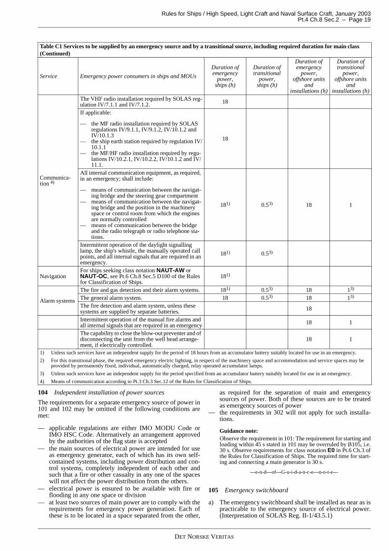
Rules for Ships / High Speed, Light Craft and Naval Surface Craft, January 2003 Pt.4 Ch.8 Sec.2 – Page 19
104 Independent installation of power sources
The requirements for a separate emergency source of power in101 and 102 may be omitted if the following conditions aremet:
— applicable regulations are either IMO MODU Code orIMO HSC Code. Alternatively an arrangement approvedby the authorities of the flag state is accepted
— the main sources of electrical power are intended for useas emergency generator, each of which has its own self-contained systems, including power distribution and con-trol systems, completely independent of each other andsuch that a fire or other casualty in any one of the spaceswill not affect the power distribution from the others.
— electrical power is ensured to be available with fire orflooding in any one space or division
— at least two sources of main power are to comply with therequirements for emergency power generation. Each ofthese is to be located in a space separated from the other,
as required for the separation of main and emergencysources of power. Both of these sources are to be treatedas emergency sources of power
— the requirements in 302 will not apply for such installa-tions.
Guidance note:Observe the requirement in 101: The requirement for starting andloading within 45 s stated in 101 may be overruled by B105, i.e.30 s. Observe requirements for class notation E0 in Pt.6 Ch.3 ofthe Rules for Classification of Ships. The required time for start-ing and connecting a main generator is 30 s.
---e-n-d---of---G-u-i-d-a-n-c-e---n-o-t-e---
105 Emergency switchboard
a) The emergency switchboard shall be installed as near as ispracticable to the emergency source of electrical power.(Interpretation of SOLAS Reg. II-1/43.5.1)
Communica-tion 4)
The VHF radio installation required by SOLAS reg-ulation IV/7.1.1 and IV/7.1.2. 18
If applicable:
— the MF radio installation required by SOLAS regulations IV/9.1.1, IV/9.1.2, IV/10.1.2 and IV/10.1.3
— the ship earth station required by regulation IV/10.1.1
— the MF/HF radio installation required by regu-lations IV/10.2.1, IV/10.2.2, IV/10.1.2 and IV/11.1.
18
All internal communication equipment, as required, in an emergency; shall include:
— means of communication between the navigat-ing bridge and the steering gear compartment
— means of communication between the navigat-ing bridge and the position in the machinery space or control room from which the engines are normally controlled
— means of communication between the bridge and the radio telegraph or radio telephone sta-tions.
181) 0.53) 18 1
Intermittent operation of the daylight signalling lamp, the ship's whistle, the manually operated call points, and all internal signals that are required in an emergency.
181) 0.53)
NavigationFor ships seeking class notation NAUT-AW or NAUT-OC, see Pt.6 Ch.8 Sec.5 D100 of the Rules for Classification of Ships.
181)
Alarm systems
The fire and gas detection and their alarm systems. 181) 0.53) 18 13)
The general alarm system. 18 0.53) 18 13)
The fire detection and alarm system, unless these systems are supplied by separate batteries. 18
Intermittent operation of the manual fire alarms and all internal signals that are required in an emergency 18 1
The capability to close the blow-out preventer and of disconnecting the unit from the well head arrange-ment, if electrically controlled.
18 1
1) Unless such services have an independent supply for the period of 18 hours from an accumulator battery suitably located for use in an emergency.
2) For this transitional phase, the required emergency electric lighting, in respect of the machinery space and accommodation and service spaces may be provided by permanently fixed, individual, automatically charged, relay operated accumulator lamps.
3) Unless such services have an independent supply for the period specified from an accumulator battery suitably located for use in an emergency.
4) Means of communication according to Pt.3 Ch.3 Sec.12 of the Rules for Classification of Ships.
Table C1 Services to be supplied by an emergency source and by a transitional source, including required duration for main class (Continued)
Service Emergency power consumers in ships and MOUs
Duration of emergency
power, ships (h)
Duration of transitional
power, ships (h)
Duration of emergency
power, offshore units
and installations (h)
Duration of transitional
power, offshore units
and installations (h)
DET NORSKE VERITAS

Rules for Ships / High Speed, Light Craft and Naval Surface Craft, January 2003Pt.4 Ch.8 Sec.2 – Page 20
b) Where the emergency source of electrical power is a gen-erator, the emergency switchboard shall be located in thesame space unless the operation of the emergency switch-board would thereby be impaired. (Interpretation of SOLAS Reg. II-1/43.5.2)
c) In normal operation, the emergency switchboard shall besupplied from the main switchboard by an interconnectingfeeder. This feeder shall be protected against overload andshort circuit at the main switchboard, and shall be discon-nected automatically at the emergency switchboard uponfailure of the supply from the main source of electricalpower. (Interpretation of SOLAS Reg. II-1/43.5.4)
d) Where the emergency switchboard is arranged for the sup-ply of power back to the main distribution system, the in-terconnecting cable shall, at the emergency switchboardend, be equipped with switchgear suitable for at least shortcircuit protection.
e) The emergency switchboard and emergency distributionboards shall be as defined in Sec.1 and not be consideredas part of the main distribution system, even though sup-plied from such during normal operation.
f) Technical requirements for functionality and constructionfor main switchboards, apply to emergency switchboards.
g) Provision shall be made for the periodic testing of thecomplete emergency system and shall include the testingof automatic starting arrangements. (Interpretation of SOLAS Reg. II-1/43.7)
h) No accumulator battery, except the starting battery for theemergency generator prime mover, shall be installed in thesame space as the emergency switchboard. (Interpretationof SOLAS Reg. II-1/43.5.3)
i) Cables between equipment installed in the emergencygenerator room, shall be run inside the boundary of theroom. If, for exceptional reasons, it is accepted that cablespasses this boundary, fire resistant cable shall be used.
C 200 Transitional source
201 Transitional source of emergency electrical power
a) The transitional source of electrical power, where requiredby the relevant rule chapters shall consist of an accumula-tor battery suitably located for use in an emergency. Thebattery source shall be able to operate, without recharging,while maintaining the voltage of the battery throughout thedischarge period as required by A200. The battery capaci-ty shall be sufficient to supply automatically, in case offailure of either the main or the emergency source of elec-trical power, for the duration specified, at least the follow-ing services, if they depend upon an electrical source fortheir operation:
— the lighting and other services required by Table C1.See notes to Table C1.
(Interpretation of SOLAS Reg. II-1/43.4)
b) A transitional source of emergency electrical power shallbe located as required for emergency power in 101, unlessit supplies power to consumers within the same space asthe transitional source itself.
c) For requirements for battery powered systems, see D100.
C 300 Emergency generators
301 Prime mover for emergency generator
a) Where the emergency source of electrical power is a gen-erator, it shall be driven by a suitable prime mover havingindependent auxiliary systems as for example fuel, venti-lation, lubrication, cooling etc. The fuel shall have a flash-
point of not less than 43°C. (Interpretation of SOLAS Reg.II-1/43.3.1.1)
b) The prime mover shall be started automatically upon fail-ure of the main source of electrical power supply. (Inter-pretation of SOLAS Reg. II-1/43.3.1.2)
c) Whenever the emergency source of power is not ready forimmediate starting, an indication shall be given in the en-gine room or at a manned control station.
302 Protective functions of emergency generating sets
a) The protective shutdown functions associated with emer-gency generating sets shall be limited to those necessary toprevent immediate machinery breakdowns.
b) Other protective functions such as overcurrent, differentialprotection, high temperature etc. shall, if installed, givealarm only, when the generator is started as an emergencysource of power. The alarm shall be given in a normallymanned location.
c) For use as a harbour generator, or in test mode, protectionas for normal generator shall be fitted. See G301.
303 Starting arrangements for emergency generating sets
a) An emergency generating set shall be capable of beingreadily started in its cold condition at a temperature of 0ºC.If this is impracticable, or the vessel is intended for opera-tion at lower ambient temperatures, provisions shall bemade for heating arrangements to ensure ready starting ofthe generating sets. (Interpretation of SOLAS Reg. II-1/44.1)
b) Emergency generating set shall be equipped with startingdevice with a stored energy capability of at least three con-secutive starts. A second source of energy shall be provid-ed for an additional three starts within 30 minutes, unlessmanual starting can be demonstrated to be effective. Onestarting motor is sufficient. (Interpretation of SOLAS Reg.II-1/44.2)
c) Stored energy for starting shall be maintained at all times,and shall be powered from the emergency switchboard.All starting, charging and energy storing devices shall belocated in the emergency generator space. Compressed airstarting systems may however be maintained by the mainor auxiliary compressed air system through a suitable non-return valve fitted in the emergency generator space. (Interpretation of SOLAS Reg. II-1/44.3)
d) If accumulator batteries are used for starting of the emer-gency generator prime mover, every such prime movershall have separate batteries that are not used for any pur-pose other than the operation of the emergency generatingset.
e) If the emergency generator is equipped with an electronicgovernor, electronic AVR, priming pumps or other auxil-iaries dependent upon electric power supply for a success-ful start, power supply to this equipment shall be inaccordance with the requirements for energy for starting.
Guidance note:If the emergency generating set is arranged so as not to be auto-matically started, then manual starting may be permissible, suchas manual cranking, inertia starters, manually charged hydraulicaccumulators, or powder charge cartridges, where it can be dem-onstrated as being effective within 30 minutes.
When manual starting is not practicable, each emergency gener-ating set may be equipped with starting devices with a stored en-ergy capability of at least three consecutive starts. A secondsource of energy may be provided for three additional starts with-in 30 minutes. (Interpretation of SOLAS Reg. II-1/43.4)
---e-n-d---of---G-u-i-d-a-n-c-e---n-o-t-e---
DET NORSKE VERITAS
Rules for Ships / High Speed, Light Craft and Naval Surface Craft, January 2003 Pt.4 Ch.8 Sec.2 – Page 21
304 Emergency generator used in port
a) The emergency source of power may be used during timein port for the supply of the ship mains, provided the re-quirements for available emergency power is adhered to atall times.
b) To prevent the generator or its prime mover from becom-ing overloaded when used in port, arrangements shall beprovided to shed sufficient non-emergency loads to ensureits continued safe operation.
c) The prime mover shall be arranged with fuel oil filters andlubrication oil filters, monitoring equipment and protec-tion devices as required for the prime mover for main pow-er generation and for unattended operation.
d) The fuel oil supply tank to the prime mover shall be pro-vided with a low level alarm, arranged at a level ensuringsufficient fuel oil capacity for the emergency services forthe required period.
e) Fire detectors shall be installed in the location where theemergency generator set and emergency switchboard areinstalled.
f) Means shall be provided to readily change over to emer-gency operation.
g) Control, monitoring and supply circuits, for the purpose ofthe use of the emergency generator in port shall be so ar-ranged and protected that any electrical fault will not influ-ence the operation of the main and emergency services.When necessary for safe operation, the emergency switch-board shall be fitted with switches to isolate the circuits.
h) Instructions shall be provided on board to ensure thatwhen the vessel is under way all control devices (e.g.valves, switches) are in a correct position for the independ-ent emergency operation of the emergency generator setand emergency switchboard. These instructions are also tocontain information on required fuel oil tank level, posi-tion of harbour or sea mode switch if fitted, ventilationopenings etc.
D. Battery Installation
D 100 General101 Capacity of accumulator batteries
Batteries that shall be used for power supply required by theserules shall be dimensioned for the time required for the intend-ed function at an ambient temperature of 0°C, unless heating isprovided.
102 Battery powered systems
a) Continuous insulation monitoring with alarm, accordingto G102, shall be installed for all insulated distributionsystems. For battery systems not extending their circuitsoutside a single panel, this requirement is waived. Insula-tion monitoring for battery systems for non-important sys-tems below 50 V and for other systems serving onefunction only, test lamps or similar without continuousmonitoring is accepted.
b) Each battery powered system is to have a separate charg-ing device, suitable for the actual service. This may alter-natively be:
— a charging device supplied from the vessel's primaryor secondary electric distribution. Such charging de-vices are considered as important consumers
— a charging dynamo driven by one of the engines whichthe battery normally supplies, except that this is not al-lowed for auxiliary engines for emergency generatorand emergency fire pump.
c) Each starting battery required by these rules shall have anindependent charging device.
d) Each charging device is, at least, to have sufficient ratingfor recharging to the required capacity within 6 hours,while the system has normal load.
e) A battery charger shall have automatically regulatedcharging and operate on floating service with the batteryand give trickle charging when the battery is fully charged,or with change-over arrangement for full-(quick-)chargingand automatic trickle charging.
f) Charging devices shall be provided with suitable switch-gear and fusegear for protection against faults such asshort circuits, overloads and connection failures (e.g.harmful overvoltage is not to occur, if the connection withthe battery is broken). The arrangement shall further besuch that the charging devices can be disconnected formaintenance purpose, without breaking the supply to con-sumers fed by the battery.
g) Provisions shall be made for preventing reverse currentfrom the battery through the charging device.
Guidance note:When the charging dynamo is an A.C. generator (alternator), par-ticular attention should be paid to ensure that no damage wouldoccur if the connection with the battery is broken.
---e-n-d---of---G-u-i-d-a-n-c-e---n-o-t-e---
103 Battery monitoring
An alarm shall be given at a manned control station if thecharging of a battery fails, the ventilation fails or if the batteryis being discharged. (Interpretation of SOLAS Reg. II-1/43.5.3)
E. Generator Prime Movers
E 100 General
101 General
a) Each generator required according to B101 shall normallybe driven by a separate prime mover. Each generator shallbe driven by one engine, and one engine shall only driveone generator.
b) If a prime mover for a generator is also used for drivingother auxiliary machinery in such a way that it is physical-ly possible to overload the engine, an interlock or other ef-fective means for preventing such overloading shall bearranged. The availability of the generator shall be at leastas for separately driven generators.
c) When generators driven by reciprocating steam engines orsteam turbines are used, and the operation of the boiler(s)depends on electric power supply, there shall be at leastone generator driven by an auxiliary diesel engine or gasturbine on board, enabling the boiler plant to be started.
d) A generator driven by a main propulsion unit (shaft gener-ator) which is intended to operate at constant speed, e.g. asystem where vessel speed and direction are controlledonly by varying propeller pitch, may be one of the requiredgenerators according to B101. There shall be at least onegenerator driven by a separate prime mover. The capacityof separately driven generators shall be sufficient to sup-ply all essential and important services that can be expect-ed to be simultaneously in use, regardless of theoperational mode of the vessel, including stopped. Thisshall be possible without utilising any emergency powersource. (Interpretation of SOLAS Reg. II-1/41.1.3)
DET NORSKE VERITAS

Rules for Ships / High Speed, Light Craft and Naval Surface Craft, January 2003Pt.4 Ch.8 Sec.2 – Page 22
e) Shaft generator installations which do not comply with therequirement given in d), may be fitted as additionalsource(s) of power provided that:
— on loss of the shaft generator(s) or upon frequencyvariations exceeding ± 10%, a stand-by generating setis started automatically
— the capacity of the stand-by set is sufficient for theloads necessary for propulsion and safety of the ves-sel.
102 Governor characteristics
Generator prime movers shall comply with the requirements inCh.2 Sec.6.
103 Starting arrangements for main engines
a) For main engines there shall be at least two separately in-stalled batteries, connected by separate electric circuits ar-ranged such that parallel connection is not possible. Eachbattery shall be capable of starting the main engine whenin cold and ready to start condition.
b) When two batteries are serving a single main engine, achange-over switch or link arrangement for alternativeconnection of the starter motor with its auxiliary circuits tothe two batteries shall be provided.
c) Starting arrangements for two or more main engines shallbe divided between the two batteries and connected byseparate circuits. Arrangements for alternative connectionof one battery to both (or all) engines can be made, if de-sired.
d) The batteries shall be installed in separate boxes or lockersor in a common battery room with separate shelves (notabove each other).
e) Each battery shall have sufficient capacity for at least thefollowing start attempts of the engines being normallysupplied:
— 12 starts for each reversible engine— 6 starts for each non-reversible engine connected to a
reversible propeller or other devices enabling the en-gine to be started with no opposing torque.
The duration of each starting shall be taken as minimum10 s. If the starting batteries are also used for supplyingother consumers, the capacity shall be increased accord-ingly.
f) For multi-engine propulsion plants the capacity of thestarting batteries is to be sufficient for 3 starts per engine.However, the total capacity is not to be less than 12 startsand need not exceed 18 starts.
104 Starting arrangement for auxiliary engines
a) Electric starting arrangement for a single auxiliary enginenot for emergency use, shall have a separate battery, or itshall be possible to connect it by a separate circuit to oneof the main engine batteries, when such are used accordingto 103.
b) Each auxiliary engine for an emergency fire pump is tohave a separate battery.
c) When the starting arrangement serves two or more auxil-iary engines, there shall at least be two separate batteries,as specified for main engines in 103. The main engine bat-teries, when such are used, can also be used for this pur-pose.
d) Each starting battery shall have sufficient capacity for atleast three start attempts of each of the engines being nor-mally supplied. The duration of each starting shall be tak-en as minimum 10 s. If the starting batteries are also used
for supplying other consumers, the capacity shall be in-creased accordingly.
e) Power supply to electronic governors, AVRs and othernecessary auxiliaries for auxiliary engines shall, if depend-ent on external power, be arranged as required for startingarrangement in c).
F. Electric Power Distribution
F 100 Distribution in general
101 General
a) All switchboards and consumers shall be fed via switch-gear so that isolation for maintenance is possible. Contac-tors are not accepted as isolating devices.
b) Each essential or important consumer shall be connectedto a main switchboard or distribution board by a separatecircuit.
c) Two or more units, supplied from the main generators andserving the same essential or important purpose shall bedivided between at least two distribution switchboardswhen such are used, each having a separate supply circuitfrom different sections of the main switchboard(s).
102 Generator circuits
a) Each generator shall be connected by a separate circuit tothe corresponding switchboard.
b) When a generator is used for direct supply to single con-sumers, more than one generator breaker is acceptable. Insuch cases, the generator shall be de-exited and all the gen-erator's breakers opened, in case of short circuit betweenthe generator neutral point and the generator breakers.
103 Division of main bus bars
a) The main bus bars shall be divided into at least two partsby use of at least a switch disconnector or other approvedmeans. The generating sets and other duplicated essentialand important equipment shall be divided between theparts. (Interpretation of SOLAS Reg. II-1/41.4, 41.5.1.1and 41.5.1.3)
b) If the vessel is not dependent of electric power for the pro-pulsion, the division of the main bus bar is not required forlow voltage installations. (Interpretation of SOLAS Reg.II-1/41.5.2)
c) Bus tie breakers with co-ordinated protective functionswill be required where main generators serve as emergen-cy sources of power. Special requirements for bus tiebreakers may apply for additional class notations.
d) For High Speed and Light Craft category B, the main busbars shall be divided into at least two parts. Each part ofthe main bus bars with its associated generators shall be ar-ranged in separate compartments. For these vessels, b) willnot apply.
104 Power supply to control circuits for electrical installa-tions specified in this chapter
a) Power for control circuits shall generally be branched offfrom the main circuit of a consumer, with exceptions asspecified in b).For main and emergency switchboard control see H103.
b) Power for control circuits may be supplied by a controldistribution system with the following conditions:
— the power supply to control circuits for two or moreunits serving the same essential or important purpose
DET NORSKE VERITAS
Rules for Ships / High Speed, Light Craft and Naval Surface Craft, January 2003 Pt.4 Ch.8 Sec.2 – Page 23
shall be divided between at least two different distri-bution systems, with the supply complying with B102
— the power supply to each such distribution systemshall be from the same main switchboard and bus barsection as the main circuits involved. Power supplycan also be taken from battery installations construct-ed in accordance with the same requirements for re-dundancy
— the power supply for the control circuit of each essen-tial or important consumer is to have individual shortcircuit protection
— For power supply to instrumentation and automationincluding main engine electrical governor, see Pt.4Ch.9.
F 200 Lighting
201 Lighting redundancy
a) A main electric lighting system shall provide illuminationthroughout those parts of the ship normally accessible to,and used by, passengers or crew, and shall be suppliedfrom the main source of electrical power. (Interpretationof SOLAS Reg. II-1/41.2.1)
b) The arrangement of the main electric lighting system shallbe such that fire, flood or other casualty, in spaces contain-ing the main source of electrical power, associated trans-forming equipment, if any, the main switchboard and themain lighting switchboard, will not render the emergencyelectric lighting system inoperative. (Interpretation of SO-LAS Reg. II-1/41.2.2)
c) The arrangement of the emergency electric lighting sys-tem shall be such that fire, flood or other casualty, in spac-es containing the emergency source of electrical power,associated transforming equipment, if any, the emergencyswitchboard and the emergency lighting switchboard, willnot render the main electric lighting system inoperative.(Interpretation of SOLAS Reg. II-1/41.2.3)
d) If the main lighting is arranged as two separate secondarysystems, each fed from a separate transformer or convert-er, then the main lighting shall be divided between the twosystems so that with one system out of operation, there re-mains sufficient lighting to carry out all functions neces-sary for the safe operation of the vessel.
e) Redundancy requirement for generators and transformerssupplying the main lighting system is given in B101.
f) For vessels where emergency source of power not is re-quired, b) does not apply. However, the following lightingshall be divided between at least two circuits from differ-ent parts of the main switchboard:
— engine room lighting— switchboard room lighting— lighting in control room and of control positions— lighting in alleyways, stairways leading up to the boat
deck and in saloons.
Exception
For mobile offshore units covered by the MODU Code, the re-dundancy requirement in d) may be replaced by a lighting in-stallation divided between two systems, built with redundancyin technical design and physical arrangement, i.e. with one sys-tem out of operation, the remaining system shall be sufficientfor carrying out all the functions necessary for the safe opera-tion of the vessel. The emergency switchboard may be used asone of the secondary distribution systems.
The following lighting is divided between at least two circuits,one from the main and one from the emergency switchboard:
— lighting in the engine room and all control stations
— lighting in saloons, alleyways, stairways leading up to thelife boat stations and helicopter deck.
202 Navigation lights switchboard
The main navigation lights shall be connected to a dedicateddistribution switchboard, placed on the bridge or in the chartroom. This distribution switchboard shall not be used for otherpurposes, except that special signal lights such as anchor lightsand signal lights required by canal authorities can be supplied.
Guidance note:Special national requirements may apply.
---e-n-d---of---G-u-i-d-a-n-c-e---n-o-t-e---
203 Power supply to navigation lighting
a) The navigation light switchboard (controller) shall be sup-plied by two alternative circuits, one from the main sourceof power and one from the emergency source of power. Achangeover switch shall be arranged for the two supplycircuits.
b) For any cargo ship without automatic starting of the emer-gency generator and for all passenger ships, the emergen-cy power to the navigation light shall be supplied by thetransitional source of power until the emergency generatoris supplying power.
c) For vessels without emergency power the navigation light-ing shall have battery backed up supply.
204 Navigation light circuits
a) A separate circuit shall be arranged for each light connect-ed to this switchboard with a multipole circuit breaker,multipole fused circuit breaker or with a multipole switchand fuses in each phase.
b) The overload and short circuit protection for each of thesecircuits shall be correlated with the supply circuit to ensurediscriminative action of the protection devices.
c) Each light circuit shall be provided with an automaticmonitoring device, giving visual indication in the event offailure of the light, and in the event of a short circuit, whenthe light circuit is switched on.
F 300 Shore connections301 General
a) When supply from shore is used, the connection of thesupply cable from shore shall generally be carried out bysuitable terminals placed in a switchboard or in a shore-connection box with a permanent cable connection to aswitchboard.
b) In the switchboard, the circuit shall, at least, be providedwith a switch. In the shore-connection box, switchgear andprotection as required for feeder circuits shall be installed,except that overcurrent protection can be omitted if suchprotection is installed in the main switchboard.
c) If the shore connection is supplying power via the emer-gency switchboard, C105 d) shall be complied with. Fur-ther, the shore connection breaker shall be fitted with aninterlock (e.g. undervoltage release sensing the voltage onthe shore side of the breaker), so that the shore connectionis disconnected before the emergency generator or transi-tional source of power is connected.
d) For A.C. systems with earthed neutral, terminals for con-nection between the shore and ship’s neutrals shall be pro-vided.
e) For circuits rated maximum 63 A, connection by socketoutlet can be used instead of shore-connection box. Thecircuit is then to have overcurrent protection on the mainswitchboard.
DET NORSKE VERITAS

Rules for Ships / High Speed, Light Craft and Naval Surface Craft, January 2003Pt.4 Ch.8 Sec.2 – Page 24
f) Normally, high voltage shore connection circuits shall notbe used.
Guidance note:National authorities may require changeover or interlocking sys-tem, so arranged that the connection to shore cannot be fed fromthe vessel’s generators.
---e-n-d---of---G-u-i-d-a-n-c-e---n-o-t-e---
G. Protection
G 100 System protection
101 Overload protection
a) Load shedding or other equivalent arrangements shall beprovided to protect the generators, required by these rules,against sustained overload. (Interpretation of SOLAS Reg.II-1/41.5.1.2)
b) In power distribution systems that might operate in differ-ent system configurations, the load shedding shall be sucharranged that necessary system protection is functioning inall system configurations.
Guidance note:Overload protection may be arranged as load reduction or as thetripping of non-important consumers. Where more than one gen-erator is necessary to cover normal load at sea, then importantconsumers may be tripped, if necessary.
---e-n-d---of---G-u-i-d-a-n-c-e---n-o-t-e---
102 Insulation fault
a) Each insulated, or high resistance earthed primary or sec-ondary distribution system shall have a device or devicesto continuously monitor the values of electrical insulationto earth and to give an audible or visual indication in caseof abnormally low insulation values. However, audible orvisual indication can be omitted provided automatic dis-connection is arranged. The circulation current generatedby each device for insulation monitoring is not to exceed30 mA under the most unfavourable conditions. (Interpre-tation of SOLAS Reg. II-1/45.4.2)
b) The requirements in a) shall be applied on all galvanic sep-arated systems on board. Except for:
— dedicated systems for single consumers— galvanic separated local systems kept within one en-
closure.
c) On high voltage systems automatic disconnection shall bearranged for operation at 1/3 or less of the minimum earthfault current. However, for systems with high-resistanceearthed neutral or isolated neutral, this disconnection canbe replaced with an alarm when the distribution systemand equipment are dimensioned for continuous operationwith earth fault. For the requirements for voltage class ofhigh voltage cables dependent of system behaviour withearth fault, see J103.
d) On systems with low-resistance earthed neutral automaticdisconnection of circuits having insulation faults shall bearranged. This earth fault protection shall be selectiveagainst the feeding network. For low resistance earthedneutral systems the disconnection shall operate at less than20% of minimum earth fault current.
e) For direct-earthed system (TN) the three-phase overcur-rent and short circuit protection is accepted as earth faultprotection.
Guidance note:Circuits for heating cables, tapes, pads, etc. should be equippedwith earth fault breakers. See Sec.8 A400. For propulsion cir-cuits, see Sec.12.
---e-n-d---of---G-u-i-d-a-n-c-e---n-o-t-e---
103 Battery circuits
a) Circuits connected to batteries above 12 V or above 1 Ahcapacity shall have short circuit and overcurrent protec-tion. Protection may also be required for smaller batteriescapable of creating a fire risk. Short circuit protection shallbe located as close as is practical to the batteries, but notinside battery rooms, lockers, boxes or close to ventilationholes. The connection between the battery and the chargeris also to have short circuit protection.
b) Connections between cells and from poles to first shortcircuit protection shall be short circuit proof.
c) The main circuit from a battery to a starter motor may becarried out without protection. In such cases, the circuitshall be installed short circuit proof, and with a switch forisolating purposes. Auxiliary circuits, which are branchedoff from the starter motor circuit, shall be protected as re-quired in a).
104 Overvoltage protection
Overvoltage protection shall be arranged for lower-voltagesystems supplied through transformers from high-voltage sys-tems.
Guidance note:Direct earthing of the lower voltage system, or the use of voltagelimitation devices, are considered as adequate protection. Alter-natively, an earthed screen between the primary and secondarywindings may be used. See Sec.3 D400 regarding current andvoltage transformers.
---e-n-d---of---G-u-i-d-a-n-c-e---n-o-t-e---
G 200 Circuit protection201 General
a) Each separate circuit shall be protected against overcur-rent and short circuit. (Interpretation of SOLAS Reg. II-1/45.6.1)
b) All circuits serving essential or important functions shallbe separately protected.
c) Loss of protective functions shall either trip the corre-sponding equipment or give an alarm on a manned controlposition, unless other specific requirements apply.
d) Non-important motors rated less than 1 kW, and othernon-important consumers, rated less than 16A, do not needseparate protection.
e) Each final circuit supplying multiple socket outlets, multi-ple lighting fittings or other multiple non-important con-sumers shall be rated maximum 16 A in 230 V systems, 30A in 110 V systems.
f) The protective devices shall provide complete and co-or-dinated protection to ensure:
— continuity of services under fault conditions throughdiscriminative action of the protective devices
— elimination of the fault to reduce damage to the sys-tem and hazard of fire.
g) For non-important circuits, circuit breakers with insuffi-cient breaking capacity can be used, provided that they areco-ordinated by upstream fuses, or by a common upstreamcircuit breaker or fuses of sufficient breaking capacity pro-tecting the circuit breaker and connected equipment fromdamage.
DET NORSKE VERITAS

Rules for Ships / High Speed, Light Craft and Naval Surface Craft, January 2003 Pt.4 Ch.8 Sec.2 – Page 25
h) No fuse, single pole switch or single pole circuit breakershall be inserted in an earthed conductor including earthedneutral.
i) Separate cables are to be used for all circuits having sepa-rate short-circuit or overcurrent protection except that acontrol circuit, which is branched off from a main circuit,may be carried in the same cable as the main circuit. Um-bilical cables are exempted from this requirement.
j) All consumers other than motors shall be controlled by, atleast, multi-pole switchgear, except that single poleswitches can be used for luminaires or space heaters in dryaccommodation spaces where floor covering, bulkheadand ceiling linings are of insulating material.
k) The circuit breaker control is to be such that “pumping”(i.e. automatically repeated breaking and making) cannotoccur.
l) See Note 9) to Table B1 in Sec.10 for special requirementsfor protection in different locations.
Exception
For special requirements for protection of steering gear cir-cuits, see 502.
202 Capacity
a) The breaking capacity of every protective device shall benot less than the maximum prospective short circuit at thepoint where the protective device is installed.
b) The making capacity of every circuit breaker or switch in-tended to be capable of being closed, if necessary, on shortcircuit, shall not be less than the maximum value of theprospective short circuit current at the point of installation.
c) Circuit breakers in main switchboards are generally to beselected according to their rated service short circuitbreaking capacity. (ICS according to IEC 60947-2 Clause4)
d) If the main switchboard is divided by a switch disconnec-tor or a circuit breaker according to F103a) the feederbreakers in the main switchboard may be selected accord-ing to their rated ultimate breaking capacity. (ICU accord-ing to IEC 60947-2 Clause 4)
e) Provided that the main switchboard is divided by a bus tiecircuit breaker according to F103 a) and that total discrim-ination (total selectivity) of generator circuit breaker andbus tie breaker are obtained, all circuit breakers in themain switchboard may be selected according to their ratedultimate breaking capacity. (ICU according to IEC 60947-2 Clause 4)
f) Generator circuit breakers and other circuit breakers withintentional short-time delay for short circuit release shallhave a rated short-time withstand current capacity not lessthat the prospective short circuit current. (ICW accordingto IEC 60947-2 Clause 4)
g) Every protective device or contactor not intended for shortcircuit interruption shall be co-ordinated with the up-stream protection device.
h) When a switchboard has two incoming feeders, necessaryinterlocks shall be provided against simultaneously clos-ing of both feeders when the parallel connected short cir-cuit power exceeds the switchboards' short circuitstrength. A short time parallel feeding as a "make beforebreak" arrangement is accepted when arranged with auto-matic disconnection of one of the parallel feeders within30 s.
203 Fuses
a) Fuses above 320 A rating shall not be used as overloadprotection, but may be used for short circuit protection ifotherwise acceptable according to these rules.
b) Fuses for overcurrent protection shall not be rated higherthan the cable's current-carrying capacity, or the consum-ers nominal current, whichever is less.
c) Used for short circuit protection, fuses can be rated higherthan the full-load current, but not higher than expectedminimum short circuit current.
d) In high voltage equipment, fuses shall not be used forovercurrent protection of power feeder circuits. Fuses maybe used for short circuit protection provided they can beisolated and replaced without any danger of touching liveparts.
204 Short circuit protection
The general requirements for circuit protection in 201, 202 and203 apply with the following exceptions:
— separate short circuit protection may be omitted for motorsserving different functions of the same non-importantequipment for example the engine room crane may includehoisting, slewing and luffing motors. Each motor shouldhave separate overload protection and controlgear
— separate short circuit protection may be omitted at the bat-tery or bus bar end of short circuit proof installed cables.
205 Overcurrent protection
a) Overcurrent protection shall not be rated higher or adjust-ed higher (if adjustable) than the cable's current-carryingcapacity, or the consumers nominal current, whichever isless.
b) The general requirements for circuit protection in 201, 202and 203 apply with the following exceptions:overcurrent protection may be omitted for circuits supply-ing consumers having overcurrent protection in their con-trolgearthis also applies to a circuit supplying a distributionswitchboard with consumers having overcurrent protec-tion in their controlgear, provided that the sum of the ratedcurrents of the controlgears does not exceed 100% of thesupply cable's rating.
206 Control circuit protection
The general requirements for circuit protection in 201, 202 and203 apply with the following exceptions:
— protection may be omitted for monitoring circuits of auto-matic voltage regulators
— secondary side of current transformers shall not be protect-ed
— the secondary side of the single phase voltage transformersshall be protected. The protection may be in one pole(phase) only
— separate protection may be omitted for control circuitsbranched off from a feeder circuit with nominal rating lim-ited to 16 A
— separate protection may be omitted for control circuitsbranched off from a feeder circuit with nominal rating lim-ited to 25 A and when the control circuit consists of ade-quately sized internal wiring only.
Guidance note:Adequately sized wiring means that the wiring shall withstandnormal load and short circuit without reaching extreme tempera-tures.
---e-n-d---of---G-u-i-d-a-n-c-e---n-o-t-e---
DET NORSKE VERITAS
Rules for Ships / High Speed, Light Craft and Naval Surface Craft, January 2003Pt.4 Ch.8 Sec.2 – Page 26
G 300 Generator protection
301 Generator protection
a) Generators shall be fitted with overcurrent protection; setso that the generator breaker trips at maximum 125% ofnominal current, within a time delay of 120 s. Other set-tings may be accepted after confirmation of selectivityanalysis as required in Sec.1 Table B1 and Table B5 and ifcompatible with generator’s characteristic.
b) The short circuit trip shall be set at a lower value than thegenerator’s steady state short circuit current and with atime delay as short as possible, taking discrimination intoaccount. Maximum 1 s.
c) Other forms for generator overload protection, for exam-ple winding over-temperature combined with power re-lays (wattmetric relays), may substitute overcurrentprotection provided the generator cables are sufficientlyprotected.
d) Generators having a capacity of 1500 kVA or above, andall high voltage generators, shall be equipped with suitableprotection, which in the case of short circuit in the gener-ator or in the supply cable between the generator and itscircuit breaker will de-excite the generator and open thecircuit breaker. Emergency generators are exempted.
e) Each generator arranged for parallel operation shall beprovided with a reverse-power relay with a time delay be-tween 3 s and 10 s, tripping the generator circuit breakerat:
— maximum 15% of the rated power for generators driv-en by piston engines
— maximum 6% of the rated power for generators drivenby turbines.
The release power is not to depart from the set-point bymore than 50% at voltage variations down to 60% of therated voltage, and on A.C. installations at any power factorvariation.
f) Generator circuit breakers shall be provided with under-voltage release allowing the breaker to be closed when thevoltage and frequency are 85 to 110% of the nominal val-ue. The undervoltage release shall release within the range70 to 35% of it's rated voltage.
g) The arrangement of short circuit-, overcurrent- and reversepower relays shall be such that it is possible to reconnectthe circuit breaker within 30 s after a release, provided thevoltage is within the range 85 to 110% of the rated voltage.
h) See Sec.5 A301 for requirements for temperature detectorsin windings.
i) Where start and stop and load sharing between generators,is controlled by an automation system, it shall be arrangedthat the following alarms are routed to a permanentlymanned position, or to the main alarm system, in the caseof unattended operation:
— power failure to the control system— starting failure of prime mover— high and low frequency— high and low voltage— excessive percentage difference in loads (kVA or al-
ternatively both kW and kVAr) taken by the genera-tors, with the necessary time delay, when insymmetrical load sharing mode.
In addition compliance with other relevant requirements inPt.6 Ch.3 of the Rules for Classification of Ships may berequired.
j) For emergency generators special requirements apply. SeeC302.
G 400 Transformer protection
401 Transformer protection
a) Transformers shall be fitted with circuit protection as re-quired by 200.
b) If the primary side of transformers is protected for shortcircuit only, overcurrent protection shall be arranged onthe secondary side.
c) The protection system is to include an overcurrent alarm ifa load diversity factor has been used when deciding therating. The overcurrent alarm is to be initiated without anytime delay. Or alternatively co-ordinated with the overloadprotection relay to enable manual load shedding. The re-quirement is only applicable to distribution transformers.
Guidance note:When choosing the characteristics of protection devices for pow-er transformer circuits it may be necessary to take current surgeinto consideration.
---e-n-d---of---G-u-i-d-a-n-c-e---n-o-t-e---
G 500 Motor protection
501 Motor protection
a) The general requirements for circuit protection in 200 ap-ply.
b) Overcurrent protection for motors may be disabled duringa starting period.
c) Overcurrent relays shall normally be interlocked, so thatthey must be manually reset after a release.
d) Short circuit and overload protection shall be provided ineach insulated phase (pole) with the following exemp-tions:
— for D.C. motors, overcurrent relay in one pole can beused, but this cannot then substitute overcurrent re-lease at the switchboard
— for A.C. motors supplied by three-phase electric pow-er with insulated neutral, overload protection in anytwo of the three phases is sufficient
— overcurrent release may be omitted for essential orimportant motors, if desired, when the motors are pro-vided with overload alarm (for steering gear motors,see 502)
— overcurrent release in the controlgear may be omittedwhen the circuit is provided with a switch-board cir-cuit breaker with overcurrent protection
— overcurrent protection may be omitted for motors fit-ted with temperature detectors and being disconnectedupon over temperature, provided the feeding cable issufficiently protected.
e) See Sec.5 A301 for requirements for temperature detectorsin windings.
502 Steering gear protection
a) Steering gear circuits shall be disconnected upon short cir-cuit only.
b) Overcurrent and single phase operation (if three phaseequipment) shall activate alarm in a manned control posi-tion.
c) Trip due to time-delayed overcurrent relays with releasecurrent at least 200% of the full load current is accepted.
d) Fuses used for short circuit protection of steering gear cir-cuits shall be rated 200 - 300% of the full load current.
DET NORSKE VERITAS

Rules for Ships / High Speed, Light Craft and Naval Surface Craft, January 2003 Pt.4 Ch.8 Sec.2 – Page 27
H. Control
H 100 System control101 Emergency stop
a) Emergency stops of at least the following pumps and fansshall be arranged from an easily accessible position out-side the space being served. These positions should not bereadily cut off in the event of a fire in the spaces served:
— fuel oil transfer pumps— fuel oil booster pumps— other similar fuel pumps— nozzles cooling pumps when fuel oil is used as coolant— fuel oil purifiers— pumps for oil-burning installations— fans for forced draught to boilers— all ventilation fans— lubrication oil service pumps— thermal oil circulating pumps.
See Rules for Classification of Ships Ch.6 Sec.5 A300 and Pt.3Ch.3 Sec.10 A100.
b) The means provided for stopping the power ventilation ofthe machinery spaces shall be entirely separate from themeans provided for stopping ventilation of other spaces.
c) Emergency stop of thrusters and propulsion motors shallbe arranged from all control stations.
d) Emergency stops shall be independent of any remote con-trol system.
e) Requirements for emergency stop of other equipment aregiven in other parts of the rules.
102 Arrangement of emergency stop circuits
a) The arrangement of the emergency stop system shall besuch that no single failure will cause loss of duplicated es-sential or important equipment.
b) Computer based emergency stop systems shall have facil-ities to detect failures that will set the system inoperable,and give alarm to a manned position. See Ch.9 Sec.2 C.
c) Alarm for loss of power will be required for normally openemergency stop circuits.
Guidance note:Emergency stop systems may be based on both normally open(NO) and normally closed (NC) circuits, depending on the ar-rangement and the function of the system to be stopped. Systems,which can be stopped without any hazard, should be based on NCcircuits, emergency stop of propulsion motors and thrustershould be based on NO circuits.
---e-n-d---of---G-u-i-d-a-n-c-e---n-o-t-e---
103 Main and emergency switchboard control
a) Power supply for control circuits for generators breakersand generator protection shall generally be branched offfrom the main circuit (i.e. generator side for the generatorbreaker). For exception, see 104.
b) The interlocking circuit and protection relays shall be ar-ranged so that the generator circuit breaker is not depend-ent of external power sources except for external powersupplies mentioned in 104.
c) Switchboards designed and constructed entirely for re-mote operation, i.e. without or partly without local instru-mentation and control devices on the switchboard, will beaccepted. The remote control system shall comply withCh.9.
d) Where the main switchboard is arranged for remote oper-ation from a position outside the space containing the mainswitchboard, the main switchboard shall in addition be ar-
ranged for operation from a position within the space con-taining the main switchboard. This arrangement shall beindependent of the remote control outside the space con-taining the main switchboard. Measuring devices and in-strumentation positioned in the generators circuit breakercompartment do not need to be duplicated.
e) One single, common control station for several generatorscan be accepted provided that necessary precaution is tak-en with respect to separation of each of the generators con-trol cabling, instrumentation and control circuits. Thecontrol station cabinet should not be used for any otherpurposes. Where the rules require the main bus bar divid-ed, the control for each part of the main switchboard shallbe separated with flame retardant partitions, unless eachgenerator has it's own control system.
f) Any casualty within one compartment containing a gener-ator circuit breaker should not render any of the other gen-erators circuit breakers, nor their instrumentation andsignals, inoperative.
g) Automatic connection of a generator after blackout shallonly be possible when auxiliary contacts on all generatorcircuit breakers show directly that all generators are dis-connected from the main switchboard.
h) For emergency generators, a trip of a control circuit pro-tection shall not lead to uncontrolled closing of the gener-ator breaker against a live bus.
104 Control power distribution systems
a) The control power can be supplied from a battery installa-tion arranged as required for starting batteries when theswitchboard's main bus bars can be divided in two or moresections by circuit breakers or on-load switches.
b) An independent control power supply system shall be ar-ranged for each of the switchboard sections and be ar-ranged with change over possibilities.
c) The control power circuit for each generator breaker shallhave separate short circuit protection.
d) Each auxiliary control power supply system is to have suf-ficient stored energy for at least two operations of all thecomponents connected to its section of the switchboard.For switching off circuit breakers this applies for all circuitbreakers simultaneously, and without excessive voltagedrop in the auxiliary circuits, or excessive pressure drop inpneumatic systems.
105 Generator instrumentation
a) At any control position for operation of a generator break-er the following information and control signals shall beeasily and simultaneously observed by the operator:
— control signals for breaker open and breaker close— generator power (kw), if the generator is for parallel
operation— generator current. Three separate simultaneous read-
ings or alternatively one reading with a changeoverswitch for connection to all phases. if changeoverswitch is used, the current reading shall be supplied byseparate current transformers, not used for protection
— generator voltage— generator frequency— bus bar voltage— bus bar frequency— adjustment device for speed of generator prime mov-
er.
b) It shall be possible to synchronise each generator intendedfor parallel operation with two different devices. Eachsuch generator shall be able to be synchronised to its bus
DET NORSKE VERITAS

Rules for Ships / High Speed, Light Craft and Naval Surface Craft, January 2003Pt.4 Ch.8 Sec.2 – Page 28
bar by a synchronising device independent of any othersections of the switchboard.Exception:The speed set-point of any main engine driving a generatordoes not need to be accessible at the control position forthe generator breaker.
106 Main source of power and main switchboard in differentlocations
For generators installed in a space that does not have direct ac-cess to the space where the generator breaker is installed, thegenerator cable shall have short circuit protection at both ends.The generator and generator driver shall be equipped with re-mote control and alarms as required by class notation E0.
107 Sectioning of bus bars
a) Switchgear for sectioning of bus bars shall have sufficientmaking and breaking capacity for the service for which itis intended. If wrong operation may cause damage, theninstructions for correct operation shall be given by sign-board on the switchboard. It shall be clearly indicatedwhether such switchgear is open or closed.
b) Undervoltage release of sectioning switchgear is acceptedas long as the switchgear has sufficient capacity for break-ing the prospective fault current at the point of installation.
108 Parallel incoming feeders
a) Switchboards that are arranged for supply by two (ormore) alternative circuits shall be provided with interlockor instructions for correct operation by signboard on theswitchboard. Positive indication of which of the circuits isfeeding the switchboard shall be provided.
b) When a secondary distribution switchboard is supplied bytwo or more transformers or rectifiers, the circuit fromeach of these shall be provided with multipole switchgear.
c) Switchboards supplied from power transformers shall bearranged with interlock or signboard as in a) unless thepower transformers are designed for parallel operation.
d) Interlocking arrangements shall be such that a fault in thisinterlocking system cannot put more than one circuit outof operation.
e) In the case where a secondary distribution system is sup-plied by parallel operated power transformers, supplied bydifferent sections of main bus bars, necessary interlocksshall be arranged to preclude parallel operation of thetransformers when the main distribution bus ties are openor being opened.
f) Transformers shall not be energised from the secondaryside, unless accepted by the manufacturer. For high volt-age transformers, secondary side switchgear shall general-ly be interlocked with the switchgear on the primary side.This so that the transformer will not be energised from thesecondary side when the primary switchgear is opened. Ifbackfeeding through transformers is arranged, specialwarning signs shall be fitted on the primary side switch-gear. Different generators shall not feed the different sidesof transformers simultaneously (not locking generators insynchronism via a transformer).
Guidance note:Temporary back-feeding as part of a black-start procedure maybe accepted.
---e-n-d---of---G-u-i-d-a-n-c-e---n-o-t-e---
H 200 Motor control
201 Controlgear for motors
a) Each motor shall normally be provided with at least thefollowing controlgear, functioning independent of con-trolgear for other motors:
— each motor rated 1 kW or above: a multipole circuitbreaker, fused circuit breaker or contactor, with over-current release according to G500, if necessary com-bined with a controller for limiting the starting current
— each motor rated 1 kW or above: control circuits withundervoltage release so that the motor does not re-start after a blackout situation
— each motor rated less than 1 kW: a multipole switch.
For exemptions and additions regarding steering gear mo-tors, see G502.
b) Undervoltage release shall not inhibit intended automaticrestart of motor upon restoration of voltage after a black-out.
c) Common starting arrangements for a group of motors (e.g.a group of circulating fans for refrigerated cargo holds) aresubject to consideration in each case.
d) Controlgear for motors shall be designed for the frequencyof making and breaking operations necessary for the re-spective motor.
e) Switchgear for feeder circuits shall not be used as motorcontrolgear unless:
— the switchgear is designed for the frequency of mak-ing and breaking operations necessary for the respec-tive motor
— the requirements for motor controlgear otherwise arecomplied with
— the switchgear shall be of the withdrawable type if lowvoltage.
f) For requirements to emergency stop, see 101.
202 Power for motor starting
a) If the starting of a large motor requires that two or moregenerators are run in parallel, an interlock shall be provid-ed, ensuring that this circuit can only be switched on whena sufficient number of generators are connected.
b) The interlock may, however, be omitted for motors thatcan only be started from the room where the generatorbreakers are located, provided signboards with the neces-sary instructions are fitted at the starters.
I. Vessel Arrangement
I 100 General
101 Ventilation
a) All rooms where electrical equipment is located shall besufficiently ventilated in order to keep the environmentalconditions within the limits given in Sec.3 B300.
b) The heat generated by the electrical equipment itself, byother machinery and equipment, and the heat caused bysun radiation on bulkheads and decks should not lead tooperating ambient temperatures in excess of the limits list-ed in Sec.3 Table B1.
c) The air supply for internal cooling of electrical equipment(i.e. "ventilated equipment") shall be as clean and dry aspracticable. Cooling air shall not be drawn from below thefloor plates in engine and boiler rooms.
d) If forced ventilation or cooling is required, the same re-dundancy requirement applies to such equipment and its
DET NORSKE VERITAS

Rules for Ships / High Speed, Light Craft and Naval Surface Craft, January 2003 Pt.4 Ch.8 Sec.2 – Page 29
power supply as to the electrical equipment installed in theventilated or cooled area.
e) If the actual ambient air temperatures will clearly exceedthe limits listed in Sec.3 Table B1, then the equipmentshall be designed for the actual operating ambient temper-atures concerned.
102 Arrangement of power generation and distribution sys-tems
a) The integrity of the main electrical supply shall be affectedonly by fire, flood or other damage conditions, in onespace. The main switchboard shall be located as close as ispracticable to the main generating station. (Interpretationof SOLAS Reg. II-1/41.3)
b) The main generating station shall be situated within themachinery space, i.e. within the extreme main transversewatertight bulkheads. Where essential services for steer-ing and propulsion are supplied from transformers, con-verters and similar appliances constituting an essentialpart of electrical supply system they shall also satisfy theforegoing.
c) The integrity of the emergency electrical supply and thetransitional source of power shall not be affected by fire,flood or other casualty in the main electrical supply, or inany machinery space of category A. The emergencyswitchboard shall be located in the same space as theemergency generating station. (Interpretation of SOLASReg. II-1/43.1.3 and 43.1.4)
d) Normally, the space containing the emergency source ofpower and associated electrical distribution shall not becontiguous to the boundaries of machinery space of cate-gory A or those spaces containing the main source of elec-trical power and associated electrical distribution.
e) All charging and energy storing devices for necessary con-trol and instrumentation shall be located in the same spaceas the system being under control. UPSs or battery systemsfor operation of the main power distribution shall not belocated together with equipment necessary for operationof the emergency power generation or distribution, or viceversa.
Guidance note:Any bulkhead between the extreme main transverse watertightbulkheads is not regarded as separating the equipment in themain generating station provided that there is access between thespaces.The requirements in a) do not preclude the installation of supplysystems in separate machinery spaces, with full redundancy intechnical design and physical arrangement.
---e-n-d---of---G-u-i-d-a-n-c-e---n-o-t-e---
I 200 Switchboard arrangement201 Installation of switchboards
a) Switchboards shall be placed in easily accessible and well-ventilated locations, well clear of substantial heat sourcessuch as boilers, heated oil tanks, and steam exhaust or oth-er heated pipes. The ventilation shall be so arranged thatpossible water or condensation from the ventilator outletscan not reach any switchboard parts. (Interpretation of SOLAS Reg. II-1/45.2)
b) Normally, pipes shall not be installed above, or immedi-ately below, in front of or behind switchboards. If this isunavoidable, additional screening of pipes and fittings willbe required in order to protect the switchboard againstsplash, or spray, by leakage. Such screening shall be pro-vided with drains, if necessary.
c) Switchboards shall not be located immediately abovespaces where high humidity or high concentrations of oil
vapours can occur (e.g. bilge spaces), unless the switch-board has a tight bottom plate with tight cable penetra-tions.
d) The arrangement and installation of switchboards shall besuch that operation and maintenance can be carried out ina safe and efficient way. When switchgear is located closeto bulkheads or other obstructions, it shall be possible toperform all maintenance from the front.
e) Switchboards more than 7 m long shall not form dead endcorridors. Two escape routes shall be available as requiredby: SOLAS Reg. II-2/45.1.
f) Type tested assemblies or partially type tested assemblieswith smaller clearance or creepage distances than given inSec.3 D600 (i.e. as accepted by Sec.4 A110), are not ac-cepted installed in machinery space category "A".
g) For water-cooled electrical equipment seawater pipesshall be routed away from the equipment, so that any leak-age in flanges do not damage the equipment.
202 Arrangement for high voltage switchboard rooms
The space where high voltage switchboards are installed shallbe so arranged that hot gases escaping from the switchboard incase of an internal arc are led away from an operator in front ofthe switchboard.
203 Passage ways for main and emergency switchboards
a) Passages in front of main switchboards shall have a heightof minimum 2 m. The same applies to passages behindswitchboards having parts that require operation from therear.
b) The width of the front passage shall be at least 0.8 m forlow voltage, and 1 m for high voltage switchboards. Whendoors in high voltage cubicles are open there shall be atleast 0.5 m free passage left. The width of the passage be-hind a switchboard where access for operation is neces-sary, shall be at least 0.6 m, except at frames where it canbe reduced to 0.5 m. Doors in open position, or switchgeardrawn out in position for service, shall not obstruct thepassage, i.e. there shall be at least 0.4 m free passage left.(For high voltage there shall be 0.5 m left.).
c) Where switchgear needs passage behind for installationand maintenance work the free passage behind the switch-gear shall not be less than 0.6 m, except at frames where itcan be reduced to 0.5 m. For voltages above 500 V up toand including 1000 V these figures for passage behind aswitchboard shall be increased to at least 0.8 and 0.6 m, re-spectively.
d) The free passageway in front of, or behind the switch-board, shall give unobstructed access to a door for easy es-cape in case of an emergency situation occurring in theswitchgear room.
204 Distribution switchboards
a) Distribution switchboards shall be placed in accessiblespaces with enclosures as specified in Sec.10.
b) Alternatively switchboards may be placed in cupboardsmade of or lined with material that is at least flame-retard-ant, and with door, cable entrances and other openings(e.g. for ventilation) arranged so that the cupboard in itselfcomplies with the protection required in Sec.10.
c) The front of the switchboard, inside such a cupboard, is tocomply with enclosure type IP 20 with exemption for fus-es as specified in Sec.4 A104.
205 Controlgear for equipment in bunker and cargo spaces
All lighting and power circuits terminating in a bunker or cargospace shall be provided with a multiple pole switch outside thespace for disconnecting such circuits. (Interpretation of
DET NORSKE VERITAS

Rules for Ships / High Speed, Light Craft and Naval Surface Craft, January 2003Pt.4 Ch.8 Sec.2 – Page 30
SOLAS Reg. II-1/45.8)
206 Hazardous areas
For installations in hazardous areas, as for example batteryrooms, paint stores, gas bottle stores or areas that may be haz-ardous due to the cargo or processes onboard, the requirementsin Sec.11 shall be complied with.
I 300 Rotating machines301 General
a) Generating sets with horizontal shaft shall generally be in-stalled with the shaft in the fore-and-aft direction of thevessel.
b) Where a large machine is installed athwartships, it shouldbe ensured that the design of the bearings and the arrange-ments for lubrication are satisfactory to withstand the roll-ing specified in Ch.1 Sec.3 B of the Rules forClassification of Ships. The manufacturer should be in-formed when a machine for installation athwartships is or-dered.
c) Normally pipes shall not be installed above generators. Ifthis is unavoidable, additional screening of pipes and fit-tings shall be required in order to protect the generatoragainst splash, spray or leakage. Such screening shall beprovided with drains, if necessary.
I 400 Battery installations401 Application
These requirements are applicable for rechargeable batteries ofboth "vented" and "dry" type batteries.
Guidance note:The term "vented" batteries is used for rechargeable batterieswith wet electrolyte without devices for reduced emission of gas.The term "dry" batteries is used for rechargeable batteries withreduced emission of gas, such as valve regulated, sealed, gel typeor dry type batteries. Variants characterised as “sealed” or “her-metically sealed” should be regarded similar to the dry types un-less other properties are confirmed.
---e-n-d---of---G-u-i-d-a-n-c-e---n-o-t-e---
402 Hazardous area
a) No electrical equipment, except that necessary for opera-tion and being certified safe for zone 1, hydrogen atmos-phere (gas group IIC), shall be installed inside batteryrooms, lockers or boxes.
b) Motors mounted inside extract ventilation ducts for lock-ers and battery rooms, shall be certified safe as for a). Thefan itself shall be of non-sparking type.
c) Battery rooms and lockers or boxes shall be regarded aszone 2 hazardous areas with respect to access doors andpossible interference with other rooms.
403 Arrangement
a) Requirements for the location of batteries depends upontheir capacity as shown in Table I1.
b) Accumulator batteries shall be suitably housed, and com-partments shall be properly constructed and efficientlyventilated.
— the batteries shall be so located that the their ambienttemperature remains within the manufacturer’s speci-fication at all times. Normally, a location at open deckexposed to sun and frost will not be accepted
— battery cells shall be placed so that they are accessiblefor maintenance and replacement
— in battery boxes, the cells shall be placed at one heightonly. There shall be minimum 300 mm space aboveeach cell when the top cover is open
— in battery rooms and lockers and boxes with side cov-er, there shall be a minimum of 300 mm space aboveeach cell
— normally, accumulator batteries shall not be located insleeping quarters
— only batteries for starting of the emergency generator,if any, shall be installed in the same space as the emer-gency switchboard.
(Interpretation of SOLAS Reg. II-1/45.9.1 and 45.9.3)
Table I1 Battery location and ventilationBattery
capacity, (KVAh)
Minimum requirements for location and ventilation
Vented type Dry type
> 20 > 40
Location: Dedicated battery room.Ventilation:Separate mechanical ventilation with suc-tion fan, for minimum 30 changes of air per hour.The ventilation fan shall be started auto-matically when full (quick) charging is commenced, and shall be running until at least 30 minutes after the charger unit has been de-energised.The ventilation fan shall be interlocked with the charger unit in such a manner that the charger unit is de-energised if the ven-tilation fails.
> 5 and < 20 N/A
Location: Dedicated battery room or lock-er.Ventilation:Mechanical ventilation as described above or natural ventilation to free air.Natural ventilation shall be through an un-obstructed duct not inclined more than 45° from the vertical. The natural escape of air shall not be reduced by the room ventila-tion system; i.e. the room is to have posi-tive air pressure. Lockers may be located in engine rooms and similar spaces.
< 5 < 40
Location: Dedicated battery box.Ventilation:Natural ventilation directly to the room by ventilation holes at top and bottom.The room is to have an extract ventilation duct at ceiling level. The area of the room (m2), shall be at least 0.3 times battery kVAh. Ventilation rate of the room shall be at least 6 air changes per hour.
N/A < 0.2 In ventilated electrical assemblies.
DET NORSKE VERITAS

Rules for Ships / High Speed, Light Craft and Naval Surface Craft, January 2003 Pt.4 Ch.8 Sec.2 – Page 31
c) For minimum requirement for location and ventilation, seeSec.4 B 201.
404 Ventilation of battery rooms
a) Ventilation shall be arranged for all battery rooms, lockersand boxes. The air intake shall be in the lower part and canbe taken from an adjacent room being readily accessiblefrom the battery installation (e.g. ventilation from the en-gine room, for batteries with access from this room). Theair outlet shall be arranged in the upper part so that gaspockets cannot accumulate.
Guidance note:As an alternative to the above ventilation rates, the followingmay be applied:Ventilation rate, (m3/hour), for battery rooms and rooms contain-ing battery boxes:
- for vented batteries, 10 x sum of battery kVAh.- for dry batteries, 2 x sum of battery kVAh.For vented batteries, a two step ventilation system applying re-duced ventilation rate at trickle charging may be applied if the ac-tual charging current is monitored. The monitoring circuit shallautomatically switch to high ventilation rate when the value ofthe charging current in amperes, rises above 2% of the batteryampere hours value. Switching to low ventilation rate shall be bymanual operation. The low ventilation rate, (m3/hour) shall be atleast 0.002 x sum of battery VAh.In case of natural ventilation by openings to the room or by ex-tract duct to free air, the following is given for cross section(cm2) of openings and duct. Except for boxes, the inlet shall beof same size as the outlet.
- for dry batteries, 20 x battery kVAh.- for vented batteries, 50 x battery kVAh.- for dry batteries located in electrical panels, 500 x battery
kVAh.
---e-n-d---of---G-u-i-d-a-n-c-e---n-o-t-e---
405 Charging station for battery powered fork lift
a) A charging station is defined as a separate room, only usedfor this purpose, or a part of a large room, for example acargo hold, based on the area occupied by the fork lift plus1 m on all sides.
b) Socket outlets for the charging cables, mechanically orelectrically interlocked with switchgear, can be placed inthe charging station. Such socket outlets shall have at leastenclosure IP 44 or IP 56, depending upon the location (seeSec.10 Table B1). In general no other electrical equip-ment, except explosion protected equipment (according toSec.12) as specified for battery rooms may be installed.
c) Charging stations shall generally be mechanically venti-lated with at least 30 changes of air per hour. An arrange-ment as specified for battery rooms with battery capacityin accordance with the actual battery capacity, but not lessthan 20 kVAh shall be used, see 304. For charging stationsin cargo holds having mechanical overpressure ventila-tion, an alternative arrangement shall provide a naturalventilation outlet duct of sufficient capacity from the up-per part of the charging station to free air.
I 500 Cable routing501 General
a) Cable runs shall be installed well clear of substantial heatsources such as boilers, heated oil tanks, steam, exhaust orother heated pipes, unless it is ensured that the insulationtype and current rating is adapted to the actual tempera-tures at such spaces.
b) Cables and wiring serving essential, important or emer-gency installations shall be routed clear of galleys, ma-chinery spaces and their casings and other high fire risk
areas, except for supplying equipment in those spaces.They shall not be run such that heating through fire divi-sions may jeopardise the function of the cable. Special at-tention shall be given to the protection and routing of maincable runs for essential installations, for example betweenmachinery spaces and the navigation bridge area, takinginto account the fire risk existing in accommodation spac-es. (Interpretation of SOLAS Reg. II-1/45.5.3)
c) For installations in connection with hazardous areas, re-quirements for selection of cables, cable routing and fix-ing, see Sec.11. (Interpretation of SOLAS Reg. II-1/45.5.4)
d) Other requirements for cable routing and installation arelocated in Sec.10.
e) The cable routing shall be such that in case of a local firein the machinery space category A it is not likely that thecables to both duplicated consumers will be damaged.
f) In areas where it is impossible to separate the cable runs,they shall be protected against direct exposure to fire (e.g.screens or ducts or fire-protecting coating).
g) Cables may exceptionally be routed through high fire riskarea, but shall then have additional fire protection, e.g. byusing cable tested in accordance with IEC 60331.
Guidance note:Main cable runs are for example:
- cable runs from generators and propulsion motors to main andemergency switchboards
- cable runs directly above or below main and emergencyswitchboards, centralised motor starter panels, section boardsand centralised control panels for propulsion and essentialauxiliaries.
---e-n-d---of---G-u-i-d-a-n-c-e---n-o-t-e---
502 Separation of cables for emergency services, essentialand important equipment
a) Where it is required to divide a ship into fire zones cableruns shall be arranged so that fire in any main vertical firezone will not interfere with essential services in any othersuch zone. (Interpretation of SOLAS Reg. II-1/45.11)
b) The cables for duplicated steering gear motors are to beseparated throughout their length as widely as is practica-ble. This also applies to control circuits for the steeringgears motor starters, and to cables for remote control of therudder from the bridge.
503 Separation of main generators or main power convert-ers cabling
Cables for generators, transformers and converters requiredaccording to Sec.2, shall be divided between two or more cableruns. These cable runs shall be routed as far away from eachother as practicable and away from machinery having an in-creased fire risk.
I 600 Lightning protection601 General
a) All vessels with masts or topmasts made of non-conduc-tive material shall be provided with lightning protection.
b) A lighting conductor shall be fitted on all non-metal mastson craft with a non-metal hull.
c) Primary conductors provided for lightning discharge cur-rents shall have a minimum cross section of 70 mm2 incopper or equivalent surge carrying capacity in alumini-um.
d) The conductor shall be fastened to a copper spike of min-imum diameter 13 mm reaching a minimum of 150 mmabove the mast. The conductor shall terminate to a copper
DET NORSKE VERITAS

Rules for Ships / High Speed, Light Craft and Naval Surface Craft, January 2003Pt.4 Ch.8 Sec.2 – Page 32
plate with a minimum area of 0.2 mm2 attached to the hulland so located that it is immersed under all conditions ofheel.
e) Craft with a metal hull shall be fitted with a lightning con-ductor on all non-metal masts. The conductor shall be asrequired in c) and be terminated to the nearest point of themetal hull.
I 700 Earthing of aluminium superstructures on steel vessels
701 General
Aluminium superstructures that are provided with insulatingmaterial between aluminium and steel in order to prevent gal-vanic action, are to be earthed to the hull. For this purpose, cor-rosion-resistant metal wires or bands are to be used. Thedistance between each such connection is to be maximum 10m. The sum of conductivities of all connections for one super-structure is not to be less than 50 mm2 copper, and the conduc-tivity of each connection is not to be less than 16 mm2 copper.
Provisions are to be made for preventing galvanic action at theterminals of these connections (e.g. by using “Cupal” termi-nals when copper wires or bands are connected to the alumin-ium constructions).
Guidance note:With regard to radio interference, it may be necessary to useshorter spacing between the connections than the 10 m specifiedabove.
---e-n-d---of---G-u-i-d-a-n-c-e---n-o-t-e---
J. Cable Selection
J 100 General
101 General
These technical requirements for cables and cable installationsare considered relevant for the system design phase of aproject. However, they apply as well to the final installation onthe vessel.
Other relevant requirements related to cables can be foundelsewhere in the rules, especially:
— I501- requirements for the routing of electric cables— Sec.9 - technical requirements for cables as electrical com-
ponents— Sec.10 - requirements for the installation of cables— Sec.11 - requirements for cables used in hazardous areas.
102 Fire resistant cables
a) Cables for services, required to be operable under fire con-ditions are to be of fire resistant type complying with therequirements of IEC 60331, where they pass trough highfire risk areas, fire zones or decks other than those whichthey serve.
b) Systems that are self-monitoring, fail safe or duplicatedwith runs as widely as is practicable may be exempted pro-vided that their functionality can be maintained.
Guidance note:The following emergency services are required to be operableunder fire conditions:
- fire and general alarm system- fire extinguishing systems and fire extinguishing medium
alarms- fire detection system- control and power systems to power operated fire doors and
status indication for all fire doors
- control and power systems to power operated watertight doorsand their status indication
- emergency lighting- public address system- Low Location Lighting.
---e-n-d---of---G-u-i-d-a-n-c-e---n-o-t-e---
Guidance note:Machinery, machinery parts or equipment handling combustiblesare considered to present an increased fire risk.
---e-n-d---of---G-u-i-d-a-n-c-e---n-o-t-e---
103 Voltage rating
a) The rated voltage of a cable shall not be less than the nom-inal voltage of the circuits in which it is used.
b) In systems with high-resistance earthed neutral, withoutautomatic disconnection of circuits having insulationfaults, and on every system with insulated neutral (IT-sys-tems), the rated phase to earth voltage (U0) of the cablesshall not be less than given in Table J1.
Guidance note:
- 0.6/1 kV cables may be accepted in 690 V distribution system- 3.6/6 kV cables may be accepted in 6.6 kV distribution system
with automatic disconnection upon earth fault if accepted bymanufacturer.
---e-n-d---of---G-u-i-d-a-n-c-e---n-o-t-e---
104 Colour code on earthing cable
Yellow/green colour code on conductors shall only be used forprotective earthing.
J 200 Cable temperature201 Cable temperature class
The temperature class of power cables shall be at least 10°Cabove the ambient temperature. However, 60°C power cablesare generally not permitted in engine and boiler rooms (fortemperature classes, see Sec.9).
J 300 Choice of insulating materials301 Short circuit and cable
The conductor cross-section of cables shall be sufficient to pre-vent the insulation from being damaged by high temperaturesoccurring by short circuits at the cable end. The conductor tem-perature classes are given in IEC 60092-351.
302 PVC insulated conductors
a) With reservations as specified in 201, PVC-insulated con-ductors without further protection may be used for instal-lation in closed piping system in accommodation spaces,when the system voltage is maximum 250 V. Such con-ductors may also be used for internal wiring of switch-boards and other enclosures and for control wiringinstalled in closed piping system on machinery compo-nents. Other types of flame retardant switchboard wiresmay be accepted for the same purpose. See Sec.9 D400.
Table J1 Rated voltage for high voltage cables
Highest system voltage (Um)
(kV)
Rated voltage (U0)(kV)
With automatic dis-connection upon
earth fault
Without automatic disconnection upon
earth fault7.2 3.6 6.0
12.0 6.0 8.717.5 8.7 12.024.0 12.0 18.036.0 18.0 -
DET NORSKE VERITAS

Rules for Ships / High Speed, Light Craft and Naval Surface Craft, January 2003 Pt.4 Ch.8 Sec.2 – Page 33
b) Due to brittleness at low temperatures, cables with PVCinsulation and or main (inner) sheath, shall normally notbe installed in refrigerated chambers, and holds for tem-peratures below – 20°C, or across expansion joints onweather decks.
303 Rubber insulated cables
Due to poor mechanical strength, the use of silicon-rubber-in-sulated cables is limited to applications where a high tempera-ture resistant cable is necessary (where the ambienttemperature can be above 70°C).
J 400 Current rating401 Earthing connections and conductors
a) All earthing connections of copper shall have sufficientcross-section to prevent the current density exceeding 150A/mm² at the maximum earth fault currents that can passthrough them.
b) Minimum cross-section of earthing conductors shall be aslisted in Table J2.
402 Conductor current rating
The highest continuous load carried by a cable shall not exceedthe current rating specified in Tables J2 to J6, with considera-tion given to the correction factors given in 500.
J 500 Correction factors501 Different temperature classes
If cables of different temperature classes are carried in thesame bunch or pipe, the current ratings for all cables shall bebased on the lower temperature class.
502 Multicore cables
For cables with more than 4 cores, the current rating are givenby the following equation:
N = number of cores
J1 = the current rating for a 1-core cable.
This applies by equal load on all cores. If some cores in suchmulti-core cables are not used, or are used for very small cur-rents only, the current rating for the other cores may be in-creased after consideration in each case.
503 Ambient temperature
When the actual ambient air temperature clearly differs from45°C, the correction factors as given in Table J6 apply.
504 Bunching
The current ratings specified in the Tables J3 to J5 are based onmaximum 6 cables, which can be expected to be under full loadsimultaneously being bunched together. If bunching of largerformations is used for cables expected to be under full load si-multaneously, a correction factor of 0.85 shall be applied.
505 Periodic load
For cables used for loads that are not continuous, i.e. operatesfor periods of half or one hour and the periods of no-load islonger than 3 times the cable time constant T (in minutes), thecurrent rating may be increased by a duty factor, Df, calculatedfrom:
ts = the service time of the load currents in minutesT = cable's time constant
= 0.245 d 1.35
d = overall diameter of the cable in mm.
506 Intermittent load
Cables used for loads that are not continuous, are repetitive andhave periods of no-load of less than 3 times the cable time con-stant T (in minutes), the current rating may be increased by anintermittent factor, If, calculated from:
ts = the service time of the load currents in minutes
Table J2 Earthing connections and conductors
Arrangement of earth conductor
Cross-section Q of associated current carrying conductor (One phase or pole)
(mm²)
Minimum cross-section of earth conductor
1 i) Insulated earth conductor in cable for fixed installation.
ii) Copper braid of cable for fixed installation.
iii) Separate, insulated earth conductor for fixed installation in pipes in dry accommodation spaces, when carried in the same pipe as the supply cable.
iv) Separate, insulated earth conductor when installed inside enclosures or behind covers or panels, including earth conductor for hinged doors as specified in 203.
Q ≤ 16 Q16 < Q 1/2 of the current-carrying conductor, but not
less than 16 mm²
2 Uninsulated earth conductor in cable for fixed installation, be-ing laid under the cable's lead sheath, armour or copper braid and in metal-to-metal contact with this.
Q ≤ 2.5 1 mm2
2.5 < Q ≤ 6 1.5 mm2
6 < Q Not permitted3 Separately installed earth conductor for fixed installation other
than specified in 1 iii) and 1 iv).Q < 2.5 Same as current-carrying conductor subject
to minimum 1.5 mm² for stranded earthing connection or 2.5 mm² for unstranded earth-ing connection
2.5 < Q ≤ 120 1/2 of current-carrying conductor, but not less than 4 mm²
120 < Q 70 mm2
4 Insulated earth conductor in flexible cable. Q ≤ 16 Same as current-carrying conductor16 < Q 1/2 but minimum 16 mm2
JN Jl / N3=
Df1.12
1 et– s T⁄
–------------------------=
If1 e
t– p T⁄–
1 et– s T⁄
–------------------------=
DET NORSKE VERITAS

Rules for Ships / High Speed, Light Craft and Naval Surface Craft, January 2003Pt.4 Ch.8 Sec.2 – Page 34
tp = the intermittent period in minutes (i.e. the total period be-fore of load and no-load before the cycle is repeated)
ts, T and d, see 505.
J 600 Parallel connection of cables
601 General
a) Parallel connection can be used for cables having conduc-tor cross-section 10 mm² or above. All cables that are par-allel connected shall be of the same length and cross-section. The current-carrying capacity is the sum of allparallel conductors' current-carrying capacities.
b) A two, three or four-core cable, in which all cores are ofthe same cross-section, can be used as single-core cable byparallel connection of all cores in each end. The current-carrying capacity of such single-core cable is the sum ofthe cores' current-carrying capacities.
c) With parallel connection of multi-core cables, one core ofeach cable shall be used for each phase and neutral con-nection, respectively.
d) With many parallel-connected cables, the current distribu-tion may be uneven. However, no single cable shall, afterinstallation, carry more than its capacity. This shall bedemonstrated at full load of the consumer.
J 700 Additional requirements for A.C. installations, and special D.C. installations
701 General
a) Generally, multi-core cables shall be used on A.C. instal-lations.
b) On three-phase, four-wire circuits, the cross-section of theneutral conductor shall be the same as for a phase conduc-tor up to 16 mm2, and at least 50% of that of a phase con-ductor for larger cross-sections, though not larger than 50mm2. The braiding in a cable is not accepted used as theneutral conductor.
702 Single-core cables
a) Single-core cables are not to have steel-wire braid or ar-mour.
b) Single-core cables for the same circuit shall be laid closelytogether, except for the ventilation spaces when such arenecessary (see 504) and shall be laid under the same clipsor in the same pipe, so that the bunch is not divided by anymagnetic material. Cable penetrations and glands for sin-gle-core cables shall be of non-magnetic material. If twoor more parallel-connected cables per phase are used, thedistribution of the different phases shall be such that thecurrent distribution becomes as equal as possible.
c) For D.C.-installations with a high "ripple" content (e.g.thyristor (SCR) units), a) and b) are applicable.
d) See Sec.10 C506 for fixing of single core cables.
J 800 Rating of cables
801 Rating of cables with temperature class 60°C is given inTable J3.
802 Rating of cables with temperature class 85°C is given inTable J4.
Table J3 Rating of cables with temperature class 60°CNominal
cross-sec-tion (mm2)
Current rating(Based on ambient temperature 45°C)
Single-coreA
2-coreA
3 or 4-coreA
11.52.5
81217
71014
68
1246
10
222940
192534
152028
162535
547187
466074
385061
5070
105135
89115
7495
95120150
165190220
140162187
116133154
185240300
250290335
213247285
175203235
400500630
D.C. A.C. D.C. A.C. D.C. A.C.390450520
380430470
332383442
323365400
273315364
266301329
Table J4 Rating of cables with temperature class 85°C Nominal
cross-sec-tion (mm2)
Current rating (A)(Based on ambient temperature 45°C)
Single-core 2-core 3 or 4-core1
1.52.5
162028
141724
111420
46
10
384867
324157
273447
162535
90120145
77102123
6384102
5070
180225
153191
126158
95120150
275320365
234272310
193224256
185240300
415490560
353417476
291343392
400500630
D.C. A.C. D.C. A.C. D.C. A.C.650740840
630680740
553629714
536578629
445518588
441476518
DET NORSKE VERITAS

Rules for Ships / High Speed, Light Craft and Naval Surface Craft, January 2003 Pt.4 Ch.8 Sec.2 – Page 35
803 Rating of cables with temperature class 95°C is given inTable J5.
804 Correction factors for ambient temperature are given inTable J6.
Table J5 Rating of cables with temperature class 95°C Nominal
cross-sec-tion (mm2)
Current rating (A)(Based on ambient temperature 45°C)
Single-core 2-core 3 or 4-core1
1.52.5
202432
172027
141722
46
10
425575
364764
293953
162535
100135165
85115140
7095
1165070
200255
175217
140179
95120150
310360410
264306349
217252287
185240300
470570660
400485560
329400460
Table J6 Correction factors for ambient temperatureCable temperature
class Ambient temperature (°C)
°C 35 1) 40 45 50 55 60 65 70 75 80 8560 2) 1.29 1.15 1.00 0.82 - - - - - - -75 1.15 1.08 1.00 0.91 0.82 0.71 0.58 - - - -85 1.12 1.06 1.00 0.94 0.87 0.79 0.71 0.61 0.50 - -95 1.10 1.05 1.00 0.95 0.89 0.84 0.77 0.71 0.63 0.55 0.45
1) Correction factors for ambient temperature below 40°C will normally only be accepted for:
— cables in refrigerated chambers and holds, for circuits which only are used in refrigerated service— cables on vessel with class notation restricting the service to non-tropical water.
2) 60°C cables shall not be used in engine and boiler rooms.
DET NORSKE VERITAS

Rules for Ships / High Speed, Light Craft and Naval Surface Craft, January 2003Pt.4 Ch.8 Sec.3 – Page 36
SECTION 3EQUIPMENT IN GENERAL
A. General Requirements
A 100 References101 General
a) This section contains technical requirements for all electri-cal equipment in general. Additional requirements for spe-cial types of equipment can be found in Sec.4 to Sec.9.
b) Requirements for electrical systems as a whole can befound in Sec.2. Requirements for installation of equipmentcan be found in Sec.10.
102 Compliance with standards
The requirements in this section are based on the IEC standardsystem in general.
Guidance note:IEC Standards covering the general requirements for electricalcomponents for ships are: IEC 60092-101 ”Definitions and gen-eral requirements”, and parts of IEC 60092-201 “Systems design- General”.For offshore units: IEC 61892, part 1, ”General requirements andconditions”, part 2 “Systems design”, and part 3 “Equipment”,apply.
---e-n-d---of---G-u-i-d-a-n-c-e---n-o-t-e---
B. Environmental Requirements
B 100 Inclinations101 General
a) Electrical equipment and components on ships and HS,LC and NSC shall be designed to operate satisfactorily un-der the following inclinations of the vessel:
— static conditions: list 15º, trim 5°— dynamic conditions: rolling ±22.5º, pitch ±7.5º (may
occur simultaneously)
b) Emergency installations on ships and HS, LC and NSC,except as stated in c), shall be designed to operate satisfac-torily under the following inclinations of the vessel:
— static conditions: list 22.5°, trim 10°.
(Interpretation of SOLAS Reg. II-1/43.6)
c) On ships for the carriage of liquefied gases and chemicals,the emergency power supply is to remain operational withthe ship flooded up to a maximum final athwart ship incli-nation of 30º, when the deck is not immersed.
d) For mobile offshore units the inclination values are as fol-lows:
— inclination 15° from normal level in any direction un-der normal static conditions
— inclination 22.5° from normal level in any directionunder normal dynamic conditions
— inclination 25° from normal level in any direction foremergency installations.
Guidance note:Other values may be accepted if justified by calculations for theparticular vessel or offshore unit.
National authorities may require larger inclinations.
---e-n-d---of---G-u-i-d-a-n-c-e---n-o-t-e---
B 200 Vibrations and accelerations
201 General
a) Electrical equipment and components shall be constructedto withstand, without malfunctioning, or electrical con-nections loosening, at least the following values:
— vibration frequency range 5 to 50 Hz with vibrationvelocity amplitude 20 mm/s
— peak accelerations ±0.6 g for vessels of length exceed-ing 90 m (duration 5 to 10 s)
— peak accelerations ±1 g for MOUs and vessels oflength less than 90 m (duration 5 to 10 s).
b) For flexible mounted equipment, special considerationsshall be given to the construction of the equipment sincelarger vibrations may occur.
B 300 Temperature and humidity
301 Ambient temperatures
a) Electrical equipment including components inside enclo-sures in switchboards etc., shall be constructed for contin-uous operation at rated load, at least within the ambient airtemperature ranges listed in Table B1 and cooling watertemperatures in 302.
b) Modifications of the equipment may be required if the ac-tual ambient air temperatures will clearly exceed the limitsin a).
c) If some equipment has a critical maximum ambient tem-perature by which it suddenly fails, this critical tempera-ture should not be less than 15°C above the limits specifiedin the table.
d) For vessels with class notation restricting the service tonon-tropical waters, the upper ambient air temperaturelimits according to Table B1 may be reduced by 10°C.
e) For electronic and instrumentation devices the require-ments in Ch.9 applies.
Guidance note:These rules do not appraise ambient conditions for transport orstorage of electrical equipment.
---e-n-d---of---G-u-i-d-a-n-c-e---n-o-t-e---
DET NORSKE VERITAS

Rules for Ships / High Speed, Light Craft and Naval Surface Craft, January 2003 Pt.4 Ch.8 Sec.3 – Page 37
302 Cooling water temperatures
Electrical equipment shall be constructed for continuous oper-ation under full rated load, at a seawater temperature rangefrom 0 to +32°C. Electrical equipment on vessels with classnotation restricting the service to non-tropical waters shall beconstructed for continuous operation at a seawater temperaturerange from 0 to +25°C.
303 Humidity
Electrical equipment shall be constructed to withstand, andfunction safely in relative humidity up to 95%.
C. Equipment Ratings
C 100 Electrical parameters
101 General
a) Unless otherwise clearly stated by the purchaser, equip-ment shall be rated for continuous duty. (Duty type S1).
b) All conductors, switchgear and accessories shall be ofsuch size as to be capable of carrying, without their respec-tive ratings being exceeded, the current which can normal-ly flow through them. They shall be capable of carryinganticipated overloads and transient currents, for examplethe starting currents of motors, without damage or reach-ing abnormal temperatures.
102 Voltage and frequency
a) Equipment connected to the system shall be constructedfor the system’s nominal frequency and voltage, and thetolerances described in Sec.2. A200.
b) With respect to fast voltage transients, equipment connect-ed to the system shall be capable of withstanding fast tran-sients with peak voltage amplitude of 5.5 times UN, andrise time or delay time of 1.2µs / 50µs.
103 Harmonic distortion
All equipment shall be designed to operate at any load up to therated load, with a supply voltage containing the following har-monic distortion:
— total harmonic content not exceeding 5% of voltage rootmean square value
— no single harmonic being greater than 3% of voltage rootmean square value.
104 Electromagnetic compatibility (EMC)
Equipment producing transient voltage, frequency and currentvariations is not to cause the malfunction of other equipmenton board, neither by conduction, induction or radiation.
C 200 Maximum operating temperatures
201 General
a) The temperature rise of enclosures and their different partsshall not be so high that fire risk, damage to the equipment,adjacent materials or danger to personnel occurs.
b) Normally, the temperature rise of enclosures for otherequipment should not exceed 50°C, or 40°C for enclosuresthat are installed in contact with flammable materials suchas wooden bulkheads. Exemptions may be considered forequipment that is especially protected against touching orsplashing of oil.
c) For luminaries, resistors and heating equipment, see Sec.8.
D. Mechanical and Electrical Properties
D 100 Mechanical strength
101 General
Equipment shall have sufficient mechanical strength to with-stand the strains they are likely to be exposed to when installed.
102 Enclosures
a) Enclosures shall be resistant to weather, oil and chemicalsand have sufficient mechanical strength when intended tobe installed in an area where risk of mechanical damageexists.
b) Metallic enclosures installed on deck or in compartmentswhere severe corrosion problems can be expected shall bemade of especially corrosion resistant material or dimen-sioned with a certain corrosion allowance.
c) Light metal alloys as i.e. aluminium shall be avoided asenclosure materials if not documented to be seawater re-sistant and installed so that local corrosion caused by con-tact does not occur.
d) Enclosures that are so placed that they are likely to bestepped or climbed on, shall be able to withstand theweight of a man. This applies for example to most electri-cal machines in the engine room, winch motors on deck,etc. A test to this effect, with a force of 1000 N applied bya flat surface 70 x 70 mm, may be carried out as type testor random test.
e) Enclosures shall withstand the ambient air temperatureswhich are specified in B, with the equipment at full load.The temperature rise of enclosures shall not be so high thatfire risk, damage to adjacent materials or danger to person-nel occurs.
f) When enclosures of other materials than metal are used,they should at least withstand immersion in water at 80°Cfor 15 minutes, without showing signs of deterioration,and the material shall be flame retardant according to IEC60092-101. A test to this effect may be carried out as typetest or random test. This also applies to screens of lumi-naires, and to windows in other enclosures, if made of oth-er material than glass.
Table B1 Ambient air temperature ranges
LocationMinimum ambient air temperature
range for continuous operation (°C)From To
1 Engine rooms, boiler rooms, galleys and similar spaces, accommodation spaces. 0 +452 Open deck, dry cargo holds, steering gear compartments, deckhouses, forecastle
spaces and similar spaces which are not provided with space heating. -25 +45
3 a) Refrigerated chambers and holds, general. The minimum temperature specified for the installation, but not
above -20
+45b) Refrigerated chambers and holds, for equipment which only is used in refrigerated
service. +35
DET NORSKE VERITAS

Rules for Ships / High Speed, Light Craft and Naval Surface Craft, January 2003Pt.4 Ch.8 Sec.3 – Page 38
103 Materials
a) Electrical equipment shall be constructed of durable non-hygroscopic materials which are not subject to deteriora-tion in the atmosphere to which it is likely to be exposed.
b) Electrical equipment shall be constructed of at least flameretardant materials.
Guidance note:Even in "dry" locations, up to 96% relative humidity with a saltcontent of 1 mg salt per 1 m³ of air may occur; in machinery spac-es also mist and droplets of fuel- and lubricating oil.
Tests for flame retardant properties are described in IEC 60092-101
---e-n-d---of---G-u-i-d-a-n-c-e---n-o-t-e---
104 Material detoriation due to cargo vapours
Where the cargo gases or vapours are liable to damage the ma-terials used in the construction of electrical apparatus, carefulconsideration shall be given to the characteristics of the mate-rials selected for conductors, insulation, metal parts, etc. As faras is practicable, components of copper and aluminium, shallbe encapsulated to prevent contact with gases or vapours.
Guidance note:Attention is drawn to the possibility of gases and vapours beingtransferred from one point to another through cables or cableducting unless appropriate precautions are taken, for example,adequate end sealing.
---e-n-d---of---G-u-i-d-a-n-c-e---n-o-t-e---
D 200 Cooling and anti-condensation
201 General
a) Where electrical equipment depends upon external cool-ing, the following shall be complied with:
— an alarm shall be initiated when auxiliary cooling orventilation motors stop running. Alternatively a flowmonitoring alarm shall be initiated
— the windings in the cooled equipment for essentialservices shall be equipped with temperature detectorsfor indication and alarm of winding temperature
— the windings in the cooled equipment for importantservices shall be equipped with temperature detectorsfor alarm at high winding temperature.
b) Where the cooling of electrical equipment depends upongeneral room ventilation only, temperature detectors in theequipment are not required.
Guidance note:These requirements will not be enforced when technically infea-sible as for example for thyristors.
---e-n-d---of---G-u-i-d-a-n-c-e---n-o-t-e---
202 Water cooled heat exchangers
a) Where cooling of equipment is arranged through air-waterheat exchangers, these shall be arranged to prevent entryof water into the equipment, whether by leakage or con-densation. Leakage alarm shall be provided.
b) Heat exchangers in high voltage equipment shall be ofdouble tube type and shall be fitted with leakage alarm.
c) The construction and certification of the air-water heat ex-changers shall comply with the requirements for pressurevessels, see Ch.7.
d) For direct water cooling of semi-conductor equipment, seeSec.7.
203 Anti condensation
a) For equipment where condensation is likely, for examplethose that are idle for long periods, heating arrangementsmay be required.
b) All high voltage converters, transformers and rotatingequipment not located in heated and ventilated spaces,shall be provided with heating elements in order to preventcondensation and accumulation of moisture. The heatingshall be automatically switched on at stand still.
c) All equipment equipped with air/water heat exchangersshall be provided with heating elements in order to preventcondensation and accumulation of moisture. The heatingshall be automatically switched on at stand still.
D 300 Termination and cable entrances301 Termination
a) All equipment shall be provided with suitable, fixed termi-nals in an accessible position with sufficient space for con-nection of the external incoming cable or wiring.
b) All connections for current-carrying parts and earthingconnections shall be fixed so that they cannot loosen by vi-bration. This also applies to fixing of mechanical partswhen found necessary.
c) Terminals for circuits with different system voltages shallbe separated, and clearly marked with the system voltage.
d) High voltage terminals, above 1000 V, shall not be locatedin the same box, or part of enclosure, as low voltage termi-nals.
e) Electrical equipment that needs to be connected to protec-tive earth according to 400 shall be provided with suitablefixed terminal for connecting a protective earth conductor.The terminal shall be identified by a symbol or legend forprotective earthing (PE).
302 Cable entrance
a) Cable entrances into enclosures shall be from below orfrom the side (except for enclosure IP 20), in order to pre-vent ingress of water or other liquids.
b) Cable entries from the top is accepted provided that the ca-ble entrance is provided with glands or MCTs preventingwater to enter the equipment.
c) Cable entrances shall be fit for the outer diameter of the ca-ble in question.
D 400 Equipment protective earthing401 General
a) Exposed metal parts of electrical machines or equipmentthat are not intended to be live but, which are liable, underfault conditions to become live, shall be earthed. Fixingdevices between a high voltage enclosure and steel hullparts are not to be relied upon as the sole earthing connec-tion of the enclosure.
b) Switchgear and controlgear assemblies shall be fitted withearth connection(s) to ensure earthing of all metallic non-current carrying parts. In main and emergency switch-boards a continuous earth-bar is required for this purpose.
c) For the interconnections within an enclosure, for examplebetween the frame, covers, partitions or other structuralparts of an assembly, the fastening, such as bolting orwelding is acceptable, provided that a satisfactory conduc-tive connection is obtained.
d) Hinged doors shall be connected to the switchboard or en-closure by a separate, flexible copper earth conductor. Inhigh voltage equipment, this conductor shall have at least4 mm² cross-section.
DET NORSKE VERITAS
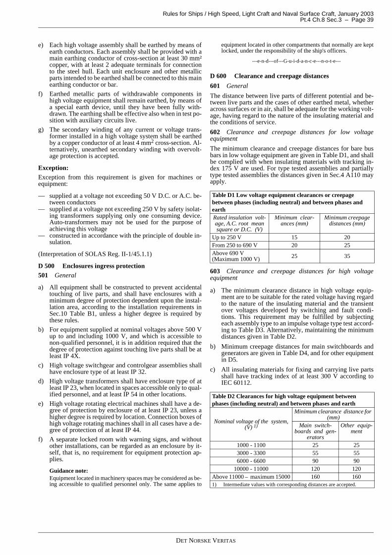
Rules for Ships / High Speed, Light Craft and Naval Surface Craft, January 2003 Pt.4 Ch.8 Sec.3 – Page 39
e) Each high voltage assembly shall be earthed by means ofearth conductors. Each assembly shall be provided with amain earthing conductor of cross-section at least 30 mm²copper, with at least 2 adequate terminals for connectionto the steel hull. Each unit enclosure and other metallicparts intended to be earthed shall be connected to this mainearthing conductor or bar.
f) Earthed metallic parts of withdrawable components inhigh voltage equipment shall remain earthed, by means ofa special earth device, until they have been fully with-drawn. The earthing shall be effective also when in test po-sition with auxiliary circuits live.
g) The secondary winding of any current or voltage trans-former installed in a high voltage system shall be earthedby a copper conductor of at least 4 mm2 cross-section. Al-ternatively, unearthed secondary winding with overvolt-age protection is accepted.
Exception:Exception from this requirement is given for machines orequipment:
— supplied at a voltage not exceeding 50 V D.C. or A.C. be-tween conductors
— supplied at a voltage not exceeding 250 V by safety isolat-ing transformers supplying only one consuming device.Auto-transformers may not be used for the purpose ofachieving this voltage
— constructed in accordance with the principle of double in-sulation.
(Interpretation of SOLAS Reg. II-1/45.1.1)
D 500 Enclosures ingress protection501 General
a) All equipment shall be constructed to prevent accidentaltouching of live parts, and shall have enclosures with aminimum degree of protection dependent upon the instal-lation area, according to the installation requirements inSec.10 Table B1, unless a higher degree is required bythese rules.
b) For equipment supplied at nominal voltages above 500 Vup to and including 1000 V, and which is accessible tonon-qualified personnel, it is in addition required that thedegree of protection against touching live parts shall be atleast IP 4X.
c) High voltage switchgear and controlgear assemblies shallhave enclosure type of at least IP 32.
d) High voltage transformers shall have enclosure type of atleast IP 23, when located in spaces accessible only to qual-ified personnel, and at least IP 54 in other locations.
e) High voltage rotating electrical machines shall have a de-gree of protection by enclosure of at least IP 23, unless ahigher degree is required by location. Connection boxes ofhigh voltage rotating machines shall in all cases have a de-gree of protection of at least IP 44.
f) A separate locked room with warning signs, and withoutother installations, can be regarded as an enclosure by it-self, that is, no requirement for equipment protection ap-plies.
Guidance note:Equipment located in machinery spaces may be considered as be-ing accessible to qualified personnel only. The same applies to
equipment located in other compartments that normally are keptlocked, under the responsibility of the ship's officers.
---e-n-d---of---G-u-i-d-a-n-c-e---n-o-t-e---
D 600 Clearance and creepage distances
601 General
The distance between live parts of different potential and be-tween live parts and the cases of other earthed metal, whetheracross surfaces or in air, shall be adequate for the working volt-age, having regard to the nature of the insulating material andthe conditions of service.
602 Clearance and creepage distances for low voltageequipment
The minimum clearance and creepage distances for bare busbars in low voltage equipment are given in Table D1, and shallbe complied with when insulating materials with tracking in-dex 175 V are used. For type tested assemblies and partiallytype tested assemblies the distances given in Sec.4 A110 mayapply.
603 Clearance and creepage distances for high voltageequipment
a) The minimum clearance distance in high voltage equip-ment are to be suitable for the rated voltage having regardto the nature of the insulating material and the transientover voltages developed by switching and fault condi-tions. This requirement may be fulfilled by subjectingeach assembly type to an impulse voltage type test accord-ing to Table D3. Alternatively, maintaining the minimumdistances given in Table D2.
b) Minimum creepage distances for main switchboards andgenerators are given in Table D4, and for other equipmentin D5.
c) All insulating materials for fixing and carrying live partsshall have tracking index of at least 300 V according toIEC 60112.
Table D1 Low voltage equipment clearances or creepage between phases (including neutral) and between phases and earthRated insulation volt-age, A.C. root mean square or D.C. (V)
Minimum clear-ances (mm)
Minimum creepage distances (mm)
Up to 250 V 15 20From 250 to 690 V 20 25Above 690 V(Maximum 1000 V) 25 35
Table D2 Clearances for high voltage equipment between phases (including neutral) and between phases and earth
Nominal voltage of the system,(V) 1)
Minimum clearance distance for (mm)
Main switch-boards and gen-
erators
Other equip-ment
1000 - 1100 25 253000 - 3300 55 556000 - 6600 90 90
10000 - 11000 120 120Above 11000 – maximum 15000 160 1601) Intermediate values with corresponding distances are accepted.
DET NORSKE VERITAS

Rules for Ships / High Speed, Light Craft and Naval Surface Craft, January 2003Pt.4 Ch.8 Sec.3 – Page 40
E. Marking and Signboards
E 100 General
101 General
a) All equipment shall be externally marked to enable identi-fication in accordance with the documentation of the pow-er distribution system, and be marked with themanufacturer's name. In addition the system voltage shallbe indicated on switchgear and assemblies.
b) All equipment shall if necessary be marked to ensure cor-rect use.
c) See Sec.11 for the requirements for the marking of hazard-ous area equipment.
d) All marking shall be made by flame retardant, non-corro-sive materials and be permanently fixed.
e) Labels bearing clear and indelible indications shall be soplaced that all components and all equipment can be easilyidentified.
102 Rating plate
All equipment shall be fitted with a rating plate giving infor-mation on make, type, current, voltage and power rating andother necessary data for the application.
Guidance note:More detailed requirements for information that shall be noted onrating plates may be found in other applicable sections regardingeach equipment type contained in this chapter (Sec.4 to Sec.9).
---e-n-d---of---G-u-i-d-a-n-c-e---n-o-t-e---
103 Labels for switchgear, terminals etc.
a) Internal components in equipment and assemblies asswitchgear, controlgear, fuse gear, socket outlets, lightingequipment and heating equipment shall be marked withmake, type, current, voltage and power rating and othernecessary data for the application (i.e. to which standardthe equipment is produced).
b) The switchgear and fuse gear for each circuit shall bemarked with circuit designation, cable cross-section andrating of fuses or necessary data for easy recognition ofcomponents and circuits according to relevant drawings.
c) If the switchboard contains two or more distribution sys-tems with different voltages, the different parts shall bemarked with the respective voltages at the partitions.
d) Terminals for circuits with different system voltages shallbe clearly separated, and clearly marked with the voltage.
e) All terminals for connection of external instrumentationand control cables, as well as the conductor ends of thesecables shall be marked for identification, preferably in ac-cordance with the designation used in the wiring diagramor schematics or loop diagrams. See also Sec.4 A100.
104 Signboards and warnings
a) Each switchgear fed from more than one individually pro-tected circuit shall be marked with a warning sign statingthat these circuits shall be isolated when the main circuit isisolated for maintenance purpose. A warning sign is notrequired if all live circuits within the enclosure are discon-nected together with the main power circuit.
b) When, for fuses above 500 V, the fuseholders permit theinsertion of fuses for lower nominal voltage, special warn-ing labels shall be placed, for example "Caution, 660 Vfuses only".
c) Special "high voltage" warning signboards are required onall high voltage machines, transformers, cables, switch-and controlgear assemblies.
F. Insulation
F 100 Insulation materials
101 General
a) Insulating materials, general purpose type, for supportingconductors (not defined as for machines and cables) shallwithstand the temperatures to which they are likely to beexposed. This is normally ambient temperature plus theheat from the conductor itself during full load.
b) A thermal classification in accordance with IEC 60085shall be assigned to the insulation system when used inmachines. The normally used classes are shown in TableF1, with the maximum exposure temperatures (includingambient) shown in the right column.
c) Insulating materials shall be at least flame retardant.
d) Insulating materials shall be tracking resistant in accord-ance with IEC 60112. A tracking index of at least 175 Vwill be required for low voltage equipment. For high volt-age equipment the tracking index shall be minimum 300
Table D3 Alternative impulse voltage type test
Rated voltage[kV]
Highest voltage for equipment
[kV]
Rated lighting impulse withstand
voltage[kV]
3.03.3 3.6 60
6.06.6 7.2 75
10.011.0 12.0 95
15.0 17.5 125
Table D4 Minimum creepage distances for high voltage main switchboards and generatorsNominal voltage
of the system,(V) 1)
Minimum creepage distance for proof (tracking index 300) (mm)
300 V 375 V 500 V > 600 V1000 - 1100 26 2) 24 2) 22 2) 20 2)
3000 - 3300 63 59 53 486000 - 6600 113 108 99 90
10000 - 11000 183 175 162 1501) Intermediate values with corresponding distances are accepted.
2) Minimum 35 mm is required for bus bars and other bare conductors in main switchboards.
Table D5 Minimum creepage distances for other high voltage equipmentNominal voltage
of the system,(V) 1)
Minimum creepage distance for proof (tracking index 300) (mm)
300 V 375 V 500 V > 600 V
1000 - 1100 18 17 15 143000 - 3300 42 41 38 366000 - 6600 83 80 75 70
10000 - 11000 146 140 130 1201) Intermediate values with corresponding distances are accepted.
DET NORSKE VERITAS

Rules for Ships / High Speed, Light Craft and Naval Surface Craft, January 2003 Pt.4 Ch.8 Sec.3 – Page 41
V. See Guidance note below, and Sec.13 (definitions) re-garding Tracking index.
Guidance note:Insulation classes shall be classified according to IEC 60085,"Recommendations for the classification of materials for the in-sulation of electrical machinery and apparatus in relation to theirthermal stability in service".Tracking index (the materials ability to withstand creep current)shall be determined according to IEC 60112, "Recommendedmethod for determining the comparative tracking index of solidinsulating materials under moist conditions".Tests according to similar national standards may be considered.
---e-n-d---of---G-u-i-d-a-n-c-e---n-o-t-e---
102 Cable insulation
For requirements regarding the insulation of electrical cables,see Sec.9.
Table F1 General insulation classesInsulation class(thermal class)
Maximum temperature(°C)
A 105B 130E 75F 155H 180
220 220
DET NORSKE VERITAS

Rules for Ships / High Speed, Light Craft and Naval Surface Craft, January 2003Pt.4 Ch.8 Sec.4 – Page 42
SECTION 4SWITCHGEAR AND CONTROLGEAR ASSEMBLIES
A. Construction
A 100 General
101 Applicable standards
Switchgear and controlgear assemblies shall generally complywith IEC 60439 and IEC 60092-302 for low voltage equip-ment, and IEC 60298 and IEC 6092-508 for high voltageequipment. In case of gas insulated, enclosed high voltage sys-tems, IEC 60466 apply.
102 General
All switchboards and assemblies shall be safe against acciden-tal touching of live conductors during normal operation of theswitchboard or assemblies. (Interpretation of SOLAS Reg. II-1/45.2)
103 Internal arc withstand
a) All switchboards and assemblies shall be safe for opera-tors in front of, or at the rear, against effects of internalarcs occurring inside the enclosure. For high voltage as-semblies, see B301. (Interpretation of SOLAS Reg. II-1/45.2)
b) A switchboard or assembly shall be designed to withstandthe short circuit forces for minimum 1 s, created by theshort circuit current and magnitude at the particular pointof the system without endangering the integrity of the out-er switchboard enclosure.
104 Accessibility
a) Instruments, handles, push buttons or other devices thatshould be accessible for normal operation are to be locatedon the front of switchboards and controlgear.
b) All other parts that might require operation are to be acces-sible. If placed behind doors, the interior front is to complywith enclosure type IP 20. When located in spaces acces-sible to non-qualified personnel, fuses with accessible cur-rent-carrying parts may be permitted, if the door islockable. Operation in this context means for example re-set of protective devices and replacement of control circuitfuses inside the assembly.
c) Doors, behind which equipment requiring operation isplaced, are to be hinged.
d) Hinged doors, which are to be opened for operation ofequipment, are to be provided with easily operated handlesor similar. There is also to be arrangements for keeping thedoors in open position.
e) All sections of switchboards and controlgear that requiremaintenance are to be accessible for maintenance work.
Guidance note:Normally, all connections of conductors, bus bar joints and me-chanical fastening of components and bus bars shall be accessi-ble for maintenance.
If the construction does not allow periodical maintenance, the as-sembly may be designed for maintenance free operation during a20-year service life.
---e-n-d---of---G-u-i-d-a-n-c-e---n-o-t-e---
105 Materials
Framework, panels and doors are normally to be of steel or alu-minium alloy, and are to be of rigid construction.
Guidance note:Switchgear and assemblies constructed of other materials may beaccepted provided requirements in Sec.3 are complied with.
---e-n-d---of---G-u-i-d-a-n-c-e---n-o-t-e---
106 Circuit separation
a) There is to be arranged a separate cubicle for each genera-tor, with flame retardant partitions between the differentgenerator cubicles and between these and other cubicles.The partitions shall withstand the effect of an internal arc,and prohibit this from spreading to other cubicles.
b) Controlgear for essential or important consumers is to beseparated from each other, and from other current carryingparts, by flame retardant partitions providing protection ofthe cubicle in case of an arcing fault occurring in theneighbouring cubicle.The arrangement shall be so that maintenance work can becarried out in each unit without danger when isolated.
c) Controlgear for non-important consumers may be in-stalled in a common cubicle provided this cubicle could beeffectively isolated.
d) Consumer controlgear installed in main switchboards areto be placed in cubicles separated from all other parts ofthe switchboard by partitions of flame retardant material.
e) Equipment for different distribution systems are to beplaced in separate switchboards (panels), or are to be sep-arated from each other by partitions clearly marked withthe actual voltages and system identifications.
f) Switchgear and controlgear assemblies supplied by differ-ent supply circuits shall not be placed in the same enclo-sure.
g) For separation due to system redundancy, see Sec.2.
107 Handrails
Main and emergency switchboards and other switchboards re-quiring operation shall have handrails of insulating materials.
108 Nameplates and marking
See Sec.3 E for general requirements regarding marking ofequipment. In addition, the following apply in front of switch-gear and controlgear assemblies, for each circuit.
a) The rating (voltage, current and fault current capabilities)of the protective devices for each circuit shall be perma-nently indicated at the location of the protective device.
b) All protection devices with adjustable settings are to havemeans that readily identify the actual setting at the locationof the protective device.
c) Circuit designation for outgoing circuits and from where,on incoming feeders.
d) Switchboards provided with more than one supply circuitare to be marked with a warning that both or all supply cir-cuits are to be disconnected before any maintenance workis carried out. Alternatively, a listing of all supply circuitsshall be located inside the switchboard.
109 "Type tested assemblies" and "Partly type tested assem-blies"
a) Electrical low voltage assemblies constructed and tested inaccordance with IEC 60092-302, item 7.1.2.101 (referringto IEC 60439-1) are accepted as long as the following con-ditions are met:
DET NORSKE VERITAS

Rules for Ships / High Speed, Light Craft and Naval Surface Craft, January 2003 Pt.4 Ch.8 Sec.4 – Page 43
— minimum clearance distance shall be 8 mm, minimumcreepage distance shall be 16 mm
— the assembly has been type tested with impulse volt-age test in accordance with IEC 60439-1
— maximum operating temperature of bus bars shall bedocumented to be acceptable with respect to fixingmaterials and internal temperature by a full currenttype test
— maximum temperature rise at termination points forexternal cables shall be 60ºC
— such assemblies shall not be installed in machineryspace category "A" (see Sec.2 I103).
b) For bus bar trunking systems where the conductors arefixed for the whole length with an insulating rail or simi-lar, distances in accordance with IEC 60947-4-1 Part 4(Contactors and motor starters - Section 1), may be accept-ed.
B. Power Circuits
B 100 Power components in assemblies
101 Main bus bar sectioning
See Sec.2 for requirements regarding main bus bar division ar-rangement.
102 Bus bar materials
a) Bus bars and other conductors shall normally be made ofcopper or copper covered aluminium.
b) Copper coated aluminium or pure aluminium bus bar shallbe adequately protected against corrosion by placing in anair conditioned environment, by special coating sealing ofthe aluminium or by the aluminium itself being seawaterresistant.
103 Rating of bus bars
a) The shape, configuration and cross-section are to be suchthat the temperature rise will not exceed 45°C at ratedload.
b) Bus bars and other conductors with their supports are to beso mechanically or thermally dimensioned and fixed thatthey can withstand for 1 s the forces occurring by the max-imum short circuit current which can occur without detri-mental effect.
c) The cross-section of bus bars for neutral connection on anA.C. three-phase, four-wire system, and for equaliser con-nection on a D.C. system, is to be at least 50% of the cross-section for the corresponding phases (poles).
d) For maximum temperatures of bus bars in type tested andpartially type tested assemblies the requirement in A110applies.
Guidance note:Reference is made to IEC 60439 for current carrying capacity ofbus bars.The general equation of current ratings at different temperaturerises is:
---e-n-d---of---G-u-i-d-a-n-c-e---n-o-t-e---
104 Fuses
Fuses shall normally comply with one of the following stand-ards:
— IEC 60269 for low voltage fuses— IEC 60282-1 for high voltage fuses.
105 Rating of copper bus bars
The maximum permissible load for bus bars with ambient tem-perature 45°C is given in Table B1.
106 Rating of aluminium bus bar
Rating of aluminium bus bar to be demonstrated by type test.
107 Circuit breakers, on-load switches, disconnectors, andcontactors
a) Switchgear and controlgear shall comply with:
— IEC 60947 for low voltage equipment— IEC 60056, IEC 60470, IEC 60129 for high voltage
equipment.
b) All fault switching and protecting components such as cir-cuit breakers and fuses are to have a fault current with-stand and interruption capacity of not less than themaximum short circuit current at the relevant point of theirinstallation.
c) All load switches and contactors are to have a rating notless than the maximum load current at their point of instal-lation. Particularly, contactors shall be protected againstthe possibility of the contactor breaking current exceedingtheir load break capacity in fault situations.
d) Fuse switches using the fuse link contacts as making andbreaking contacts are not accepted where switches are re-quired according to Sec.3, but may be used as isolatingswitch.
e) The construction is to be such that accidental making orbreaking, caused by the vessel's inclination, movements,vibrations and shocks, cannot occur.
f) Undervoltage and closing coils, including contactor coils,are to allow closing of the switchgear and controlgearwhen the voltage and frequency are 85 to 110% of the rat-ed values, and are not to cause release at voltage and fre-quency above 65% of the rated values. See Sec.2 G 301.
g) Each circuit-breaker rated more than 16 A is to be of trip-free type, i.e. the breaking action initiated by short-circuitand overcurrent relays, or by undervoltage coil, when fit-ted, is to be fulfilled independently of the position or oper-ation of manual handle or of other closing devices.
108 Switch-gear
a) Each outgoing circuit on a main switchboard or a distribu-tion switchboard is to be provided with a switch for isolat-ing purposes. One of the following solutions shall apply:
— a multipole circuit breaker— a multipole fused circuit breaker— a multipole load switch and fuses.
b) The arrangement is to be such that switches rated morethan 63A shall be accessible on the switchboard front. Fur-ther it is required that all switches can be operated, andfuses be replaced without risk of touching live parts. I.e.switchboard interior must be IP20 when operation is per-formed with open door..
c) When multipole switch and fuses are used and the switchis installed between the bus bars and the fuses, the follow-ing apply:
— the switch is to have a breaking capacity of at least 6times its full-load current
— the making capacity of the switch is to be so adaptedin relation to the fuses’ rupture characteristic that no
I1
I2----
∆ϑ1
∆ϑ2----------=
DET NORSKE VERITAS

Rules for Ships / High Speed, Light Craft and Naval Surface Craft, January 2003Pt.4 Ch.8 Sec.4 – Page 44
damage to the switch occurs even when it is closed ona short circuit.
d) On a distribution board the multipole switch may be omit-ted when maximum 63 A fuses are used.
Guidance note:For high voltage equipment switching off by an auxiliary circuitwill be accepted provided that the off–control switch is placed infront of the relevant compartment and a manual off-switchingmeans is provided at the circuit breaker when front door isopened.
---e-n-d---of---G-u-i-d-a-n-c-e---n-o-t-e---
109 Disconnection and isolation for safety purposes
Means are to be provided for the isolation of the supply to eachcontrolgear and distribution board. The following alternativearrangements may be used:
— a multipole isolating switch at the controlgear— the circuit switchgear on the switchboard from which the
controlgear or distribution board is supplied. The switch-gear used for this purpose is to be lockable in the "off" po-sition, if remote from the consumer or its controlgear
— the circuit fuses on the switchboard from which the con-trolgear or distribution board is supplied. For non-impor-tant consumers supplied by a distribution switchboard, it isaccepted that the switchgear or fuses for the supply circuitto this switchboard are used as common isolating device.The switchgear used for this purpose is to be lockable inthe "off" position
— the disconnection device for high voltage switchgear(above 1000 V) shall have visible indication of contact po-sitions.
110 Safety earthing of high voltage circuits
Each circuit is to be fitted with an integral means of earthingand short circuiting for maintenance purposes, or alternativelyan adequate number of portable earthing and short circuitingdevices, suitable for use on the equipment in question, is to bekept on board.
111 Short circuit proof internal wiring
Connections without sufficient short circuit protection for theconductor sizing are to be installed short circuit proof (definedin Sec.13).
Guidance note:This requirement applies to branching of for control power andmeasuring signals from bus bars and generator terminals, to con-ductors between batteries and short circuit protection, and to con-ductors between separated bus bar sections.
---e-n-d---of---G-u-i-d-a-n-c-e---n-o-t-e---
112 Screening of horizontally installed bus bars
Horizontally installed bus bars and bare conductors or connec-tions are to be protected by screens, if they are placed such thatthere could be a risk of anything falling down on them.
113 Clearance and creepage distances
See Sec.3 D600 for clearance and creepage distances inswitchgear and assemblies.
B 200 Batteries
201 Batteries located in electrical assemblies
a) Batteries may be installed as an integrated part of an elec-tric assembly when the battery is of dry type and has a ca-pacity less than 0.2 kVAh.
b) Batteries may be installed as a part of an electric assemblywhen the capacity of the battery is less than 5 kVAh forvented type accumulators, and less than 40 kVAh for drytype accumulators and as long as the following is com-plied with:
— the batteries shall be separated from the rest of the as-sembly with flame retardant partitions
— the battery section of the assembly shall have suitableventilation holes at top and bottom, and be designed
Table B1 Rating of copper bus bars
With x thickness
Maximum permissible loading [A] with 50/60 HzPainted (matt-black) Bare
Numbers of bars Numbers of bars1|
2||
3|||
4|| ||
1|
2||
3|||
4|| ||
15 x 3 230 390 470 - 200 350 445 -20 x 3 290 485 560 - 250 430 53520 x 5 395 690 900 - 340 620 855 -20 x 10 615 1145 1635 - 530 1020 1460 -25 x 3 355 580 650 - 300 510 615 -25 x 5 475 820 1040 - 405 725 985 -30 x 3 415 670 735 - 350 590 700 -30 x 5 555 940 1170 - 470 830 1110 -30 x 10 835 1485 2070 - 710 1310 1835 -40 x 5 710 1180 1410 - 595 1035 1350 -40 x 10 1050 1820 2480 3195 885 1600 2195 282550 x 5 860 1410 1645 2490 720 1230 1560 238050 x 10 1260 2130 2875 3655 1055 1870 2530 322060 x 5 1020 1645 1870 2860 850 1425 1785 274060 x 10 1460 2430 3235 4075 1220 2130 2850 359580 x 5 1320 2080 2265 3505 1095 1795 2170 337080 x 10 1860 2985 3930 4870 1535 2615 3460 4275
100 x 10 2240 3530 4610 5615 1845 3075 4040 4935120 x 10 2615 4060 5290 6360 2155 3545 4635 5580
DET NORSKE VERITAS

Rules for Ships / High Speed, Light Craft and Naval Surface Craft, January 2003 Pt.4 Ch.8 Sec.4 – Page 45
for air circulation upwards. There are not to be pock-ets that may accumulate gas
— the enclosure for the battery section shall have ade-quate strength so that an exploding battery does notdamage other parts of the assembly.
c) See Sec.2 I400 for requirements regarding the location andventilation of battery installations.
B 300 Additional requirements for high voltage assem-blies
301 General design and construction
a) High voltage switchgear and controlgear assemblies are tobe metal-clad in accordance with IEC 60298, or of a con-struction giving equivalent safety with respect to person-nel safety and system integrity. The switchgear shall ableto withstand an internal short circuit arcing failure with themaximum duration and magnitude, which can occur on theparticular point of the installation without harmful effectto operators.
b) The switchgear or switchboard shall be type tested to dem-onstrate that it will withstand the effects of an internal arcfailure (e.g. testing in accordance with Appendix AA ofIEC 60298).
c) There shall be separate compartments with IP rating to atleast IP 20 towards other compartments in the cubicle forat least the following components:
— control and auxiliary devices— each main switching device— components connected to one side of the main switch-
ing device (the outgoing circuit)— components connected to the other side of the main
switching device (the bus bars).
d) Normally, partitions between the compartments shall bemade of metal. Alternatively, a partition of other materialsnot intended to be earthed is accepted, provided it is veri-fied that the safety is of at least the same standard.If the main high-voltage switchgear is subdivided into twoindependent and autonomous installations, a continuousbus bar compartment is permissible, provided that a pro-tection system (arc monitor, busbar differential protection)is installed which detects internal faults and isolates the af-fected part of the installation within 100 ms, respectivelyaccidental arcing is reliable prevented by design measures(e.g. solid insulated busbar systems).
e) Means are to be provided for the disconnection and isola-tion of all circuit breakers and fused circuit breakers, eitherby using withdrawable components or by installation ofseparate disconnectors (isolators).
Exception
For final feeder circuits where energising of the main switch-ing device from the load side is not possible, the cable termi-nals and accessories (e.g. voltage and current transformers)may be placed in the same compartment as the main switchingdevice.
302 Mechanical interlocks
a) The arrangement in high voltage enclosures is to be suchthat all operation and functional testing is safeguardedagainst accidental touching of live parts.
b) Doors that can be opened for operation or testing of highvoltage parts (e.g. for replacement of fuses, or for func-tional testing of a circuit breaker) are to be interlocked sothat they cannot be opened before the components insidehave been isolated and made safe.
c) The openings between the contacts of a withdrawable highvoltage component and the fixed contacts, to which it isconnected in service, are to be provided with automaticshutters.
Guidance note:Front doors of circuit breaker compartments might be opened forcircuit breaker checking or emergency switching, without any in-terlocking, if high voltage parts still cannot be reached by acci-dental touching of the hands.
---e-n-d---of---G-u-i-d-a-n-c-e---n-o-t-e---
303 Control wiring
a) The wiring of auxiliary circuits shall, with the exception ofshort lengths of wire at terminals of instrument transform-ers, tripping coils, auxiliary contacts etc., be either segre-gated from the main circuit by earthed metallic partitions(e.g. metallic tubes) or separated by partitions (e.g. tubesor sheathed cables) made of flame retardant insulating ma-terial.
b) Fuses of auxiliary circuits, terminals and other auxiliaryapparatus requiring access while the equipment is in serv-ice, are to be accessible without exposing high voltageparts.
c) There is to be arranged an alarm for voltage loss after thelast fuses in each auxiliary power system, where a voltagefailure is not self detecting.
d) A possibility for manual operation of each circuit breakeris to be arranged. However, manual closing of the circuitbreakers is not to be possible if the arrangement of the aux-iliary circuits is such that the protection devices are put outof action and the circuit breakers are still closed after apower failure to the auxiliary circuits.
C. Control and Protection Circuits
C 100 Control and instrumentation101 General
a) See Sec.2 for requirements regarding the distribution sys-tem for control circuits, and for control and protection ofindividual consumers depending of their application andthe network system capabilities.
b) Power distribution for control circuits are generally to bebranched off from the main circuit in which the switchgearis used, with exceptions as specified in Sec.2 F104.
c) For short circuit proof installation, see B111.
102 Control of duplicated consumers
a) Control circuits for duplicated essential and importantequipment are to be kept separated from each other, andnot located in the same enclosure.
b) Controlgear for duplicated essential or important equip-ment are to be mutually independent and are to be dividedbetween two motor control centres or distribution boardshaving separate supplies from different sides of the mainswitchboard and/or the emergency switchboard.
c) Where switchboards are fitted with bus ties or bus links,the duplicated circuits shall be fed from different side ofthe bus tie.
d) Duplicated equipment for essential or important functionsshall not be dependent on any common circuits such as e.g.contactors for emergency stop.
103 Signal lamps
Signal lamps are to be arranged so that a lamp short circuit
DET NORSKE VERITAS

Rules for Ships / High Speed, Light Craft and Naval Surface Craft, January 2003Pt.4 Ch.8 Sec.4 – Page 46
cannot jeopardise the control system.
104 Panel-instruments in general
a) Instruments, including current transformers, in switchgearand controlgear shall have a nominal accuracy of 2.5% orbetter.
b) The upper limit of the scale of ampere-meters and kilo-watt-meters is to be at least 130% of the rated full load ofthe circuit. For generators arranged for parallel operation,the scale is to be arranged for reading of reverse current orpower corresponding to at least 15% of the rated full loadof the circuit. The upper limit of the scale of each voltme-ter is to be at least 120% of the nominal voltage.
c) Amperemeters, kilowattmeters and voltmeters are to beprovided with means to indicate rated current or powerand rated voltage, respectively. Instruments are to have ef-fective screening (e.g. by metal enclosures) in order to di-minish faulty readings caused by induction from adjacentcurrent-carrying parts.
105 Kilowatt meters
Normally, a kilowatt meter with connections for reading theactual three-phase load shall be used.
106 Frequency meters
Frequency meters are to have a scale ranging at least 8% aboveand below the systems operating frequencies
107 Generator instrumentation
a) Each A.C. generator shall be provided with instrumenta-tion showing:
— current for each phase— voltage— frequency.
Instrumentation for current, voltage and frequency shall bearranged for simultaneous and continuous reading.
b) When generators are arranged for parallel operation, theyshall in addition be provided with instrumentation show-ing the active power and be provided with synchronisingdevices as required by Sec.2 H105.
c) Simultaneous functional reading of current and activepower shall be provided at operating station for manualoperation and synchronisation.
Alternatives
Single voltmeters and amperemeters with switches for the al-ternative readings may be accepted.
Two separate frequency meters for several generators may beused, one with a change-over switch for connection to all gen-erators, the other connected to the bus bars. A "double frequen-cy meter" may be used for this purpose.
108 Instrumentation for distribution systems including inand outgoing circuits of switchboards
Each secondary distribution system is to be equipped with avoltmeter.
109 Instrumentation for shore connections
The shore connection circuit shall be equipped with:
— a phase sequence indicator— a voltmeter or signal lamp.
D. Inspection and Testing
D 100 General101 Factory testing
a) Switchgear and controlgear assemblies shall be tested atthe manufacturer’s works as described in 102 to 108.
b) The manufacturer shall submit test results together withthe final documentation for the equipment. The documen-tation shall give information on make, type, serial no., andall technical data necessary for the application of theswitchboard or assembly, as well as the results of the re-quired tests.
c) The following tests are required:
— function test: all basic functions, including auxiliaryfunctions, are to be tested
— insulation resistance test— high voltage test— general inspection of assembly.
102 Visual inspection
Switchboards and assemblies are subject to a visual inspectionfor verification of general workmanship, creepage and clear-ance distances, IP rating, ventilation and quality of materialsand components.
103 Function testing
a) All circuits shall be verified installed as shown in the as-build documentation.
b) Control and protection shall be tested for correct function-ing.
104 Load testing
The testing of switchgear and controlgear assemblies with fullpower, eventually together with the intended load, is not re-quired by these rules. Such tests shall be separately agreed be-tween the manufacturer and the customer.
105 Site testing
Switchgear or controlgear assemblies shall be subject to com-plete function tests with intended loading, after installation on-board. See Sec.10 D.
106 Power frequency and insulation resistance test for lowvoltage assemblies
a) Switchgear and assemblies with rated voltage above 60 Vshall be subject to a voltage test between the circuits andbetween live parts and the enclosure. The test voltage shallbe minimum equal to twice the rated voltage plus 1000 Vwith a minimum of 1500 V. The test voltage is to be ap-plied for 1 minute at any frequency between 25 and 100Hz.
b) For switchgear and assemblies with rated voltage below60 V, the test voltage given in a) shall be minimum 500 V.
c) Insulation resistance shall be measured prior to and oncompletion of the voltage test. Insulation resistance testvoltages and acceptance values are given in Sec.5 TableC3. It shall be verified that the voltage testing does notcause any reduction in switchgear insulation level. The in-sulation level shall be at least 1 MOhm.
d) The secondary winding of current transformers shall beshort circuited and disconnected from earth during the test.
e) The secondary winding of voltage transformers shall bedisconnected during the test.
Guidance note:Electronic equipment should be disconnected, short circuited andor isolated during high voltage test and insulation resistancemeasuring.
---e-n-d---of---G-u-i-d-a-n-c-e---n-o-t-e---
107 Power frequency test for high voltage assemblies
DET NORSKE VERITAS

Rules for Ships / High Speed, Light Craft and Naval Surface Craft, January 2003 Pt.4 Ch.8 Sec.4 – Page 47
a) Each high voltage assembly is to be subjected to a 1minute power frequency voltage test.
b) Replicas reproducing the field configuration of the highvoltage connections may replace voltage transformers orpower transformers. Overvoltage protective devices maybe disconnected or removed.
c) Test voltages are given in Table D1.
d) Insulation resistance shall be measured prior to and oncompletion of the voltage test. Insulation resistance testvoltages and acceptance values are given in Sec.5 TableC3. It shall be verified that the voltage testing does notcause any reduction in switchgear insulation level.
e) All auxiliary circuits are to be subjected to a 1 minute volt-age test between the circuits and the enclosure accordingto 106.
Guidance note:The environmental conditions during voltage tests are normallyto be as specified in IEC 60060-1, "High-voltage test techniques,Part 1, General definitions and test requirements", that is temper-
ature 20°C, pressure 1013 mbar and humidity 11 g water per m³(corresponding to about 60% relative humidity). Correction fac-tors for test voltages at other environmental conditions are givenin IEC 60060-1.
---e-n-d---of---G-u-i-d-a-n-c-e---n-o-t-e---
108 Test voltages for high voltage switchgear assemblies
Table D1 Test voltages for high voltage assembliesNominal voltage
of the system(kV) 1)
1 minute power frequency test voltage, (kV) (root mean square value)
To earth and between phases1 - 1.1 2.83 - 3.3 106 - 6.6 2010 - 11 28
15 381) Intermediate values for test voltages may be accepted, other than these
standard test voltages.
DET NORSKE VERITAS

Rules for Ships / High Speed, Light Craft and Naval Surface Craft, January 2003Pt.4 Ch.8 Sec.5 – Page 48
SECTION 5ROTATING MACHINES
A. General
A 100 References
101 General
The design and function of rotating machines shall generallycomply with the requirements of IEC 60092-301. For basicmachine design, the relevant parts of IEC 60034 apply.
A 200 Requirements common to generators and motors
201 Rating or duty
a) Electrical machines, including any excitation system, shallbe designed for continuous duty.
b) Unless otherwise clearly stated, the rating of electrical ma-chines shall be continuous full load duty type S1.
c) Generally, maximum environmental temperatures for ro-tating machines shall be as given in Sec.3 Table B1.
202 Insulation
a) All windings for machines are to be treated to resist mois-ture, sea air, and oil vapours.
b) For general requirements for insulation materials and ter-minations, see Sec.3 D.
203 Temperature rise in windings (insulation)
The maximum permissible heat rise in windings is given in Ta-ble A1, with these deviations:
a) If the temperature of the cooling medium will be perma-nently lower than the values given in Sec.3 B300, then thepermissible temperature rise may be increased with the
difference between the actual temperature and the temper-ature given in Sec.3 B300, up to a maximum of 25°C.
b) If the ambient temperatures clearly exceed the maximumupper limits, then the temperature rises are to be decreasedaccordingly.
c) In Table A1 allowance has been made for the temperaturein certain parts of the machine being higher than meas-ured. The temperatures at such “hot spots” are assumednot to exceed the values given in Sec.3 Table F1.
d) For vessels with class notation restricting the service tonon-tropical waters the design limits for temperature risesgiven in Table A1 may be increased by 10°C. Alternative-ly, the upper ambient air temperature limits according toTable A1 may be reduced by 10°C.
e) Where water cooled heat exchangers are used in the ma-chine cooling circuit, the temperature rise is to be meas-ured with respect to the temperature of the cooling waterat the inlet to the heat exchanger. Temperature rises givenin Table A1 may be increased by 8°C provided the inletwater does not exceed 32°C.
f) If inlet water temperature is above 32°C, permissible tem-perature rise in Table A1 may be increased by 8°C andthen reduced by the amount by which the maximum cool-ing water temperature exceeds 32°C.
g) If the inlet cooling water temperature is permanently lessthan 32°C, the permissible temperature rise in Table A1may be increased by 8°C and may be further increased byan amount not exceeding the amount by which the coolingtemperature is less than 32°C.
h) For machines with insulating class 220 the temperaturerise will be evaluated in each case.
Table A1 Limits of temperature rise of machines for vessels for unrestricted service1) based on ambient temperature of 45°C
Part of machine 1)Method of
measurement of temperature 2)
Maximum temperature rise in for air-cooled ma-chines (ºC)
Insulation classA E B F H
1. a) A.C. winding of machine having output of 5000 kVA or more
ETDR
6055
-3)
-8075
10095
125120
b) A.C. winding of machine having output of less than 5000 kVA
ETDR
6055
-70
8575
105100
125120
2. Winding of armature with commutators RT
5545
7060
7565
10080
120100
3. Field winding of A.C. and D.C. machine with excitation other than those in item 4.
RT
5545
7060
7565
10080
120100
4. a) Field windings of synchronous machines with cylindrical rotors having D.C. excitation R 85 105 130
b) Stationary field windings of D.C. machines having more than one layer
ETDRT
5545
7060
857565
10510080
130120100
c) Low resistance field windings of A.C. and D.C. machines and compensating windings of D.C. machines having more than one layer
R, T 55 70 75 95 120
d) Single-layer windings of A.C. and D.C. machines with exposed bare surfaces or varnished metal surfaces and sin-gle compensating windings of D.C. machines
R, T 60 75 85 105 130
1) Temperature rise of any part of a machine shall in no case reach such a value that there is a risk of injury to any insulating or other material in adjacent parts.
2) R indicates temperature measurement by the resistance method, T the thermometer method and ETD the embedded temperature detector method. In gen-eral for measuring the temperature of the windings of a machine the resistance method shall be applied. (See IEC 60034-1). For stator windings of ma-chines having a rated output of 5000 kW (or kVA) the ETD method shall be used. Determination by ETD method requires not less than six detectors suitably distributed throughout the winding. Highest reading shall be used to determine the temperature for the winding.
3) For high voltage machines having rated output of 5000 kVA or more, or having a core length of 1 m or more, the maximum temperature rise for class E insulation shall be decreased by 5ºC.
DET NORSKE VERITAS
Rules for Ships / High Speed, Light Craft and Naval Surface Craft, January 2003 Pt.4 Ch.8 Sec.5 – Page 49
204 Machine short time overloads
a) General purpose rotating machines shall be designed towithstand the following excess torque:
— A.C. induction motors and D.C. motors: 60% in ex-cess of the torque that corresponds to the rating, for 15s, without stalling or abrupt change in speed (undergradual increase of torque), the voltage and frequencybeing maintained at their rated value
— A.C. synchronous motors with salient poles: 50% inexcess of the torque that corresponds to the rating, for15 s, without falling out of synchronism, the voltage,frequency and excitation current being maintained attheir rated values
— A.C. synchronous motors with wound (induction) orcylindrical rotors: 35% in excess of the torque thatcorresponds to the rating, for 15 s, without losing syn-chronism, the voltage and frequency being maintainedat their rated value.
b) Induction motors for specific applications the excesstorque may be subject to special agreement. See IEC60034-1 clause 8.3.
c) General purpose rotating machines shall be designed towithstand the following excess current:
— A.C. generators: 50% in excess of the rated current fornot less than 30 s, the voltage and frequency beingmaintained as near the rated values as possible
— A.C. motors: 50% in excess of the rated current for notless than 120 s, the voltage and frequency being main-tained as near the rated values as possible
— commutator machines: 50% in excess of the rated cur-rent for not less than 60 s, operating at highest full-field speed.
205 Balance
Machines shall be so constructed that, when running at any andevery working speed, all revolving parts are well balanced.
206 Lubrication
a) Lubrication of rotating machines is to be effective underall operating conditions.
b) Each self-lubricated sleeve bearings shall be fitted with aninspection lid and means for visual indication of oil levelor use of an oil gauge. Similar requirement applies to selfcontained oil lubricated roller bearings.
c) Provision shall be made for preventing the lubricant fromgaining access to windings or other insulated or bare cur-rent-carrying parts.
207 Shafts and shaft currents
a) Shafts are to comply with the requirements in Ch.4 bothwith regard to strength, bearings and balancing.
b) Means are to be provided to prevent damaging levels ofcirculating currents between shaft, bearings and connectedmachinery.
c) When all bearings on a machine are insulated, the shaftshall be electrically connected to the machine's earth ter-minal.
208 Machine overspeed
Rotating machines are to be capable of withstanding 1.2 timesthe rated maximum speed during 2 minutes.
209 Nameplate
Each machine is to be provided with nameplate of durable,flame retardant material, giving the following information:
— make, type, serial no.— performance standard— IP rating— rated values for: output apparent power, voltage(s), fre-
quency, current(s), power factor, speed— for A.C. machines: the winding connection— thermal classification of insulation— duty type, if other than S1— maximum permissible cooling medium temperature— technical data necessary for the application of the machine— total mass.
A 300 Instrumentation of machines
301 Temperature detectors embedded in stator winding
All high voltage machines, and low voltage machines having arated output above 5000 kW (or kVA), are to be provided withtemperature detectors in their stator windings, for monitoringand alarm, also see Sec.3 D201.
Guidance note:Overvoltage protection may be required for circuits with temper-ature detectors.See Sec.12 A604 regarding rotating machines supplying or driv-ing electric propulsion and having temperature detectors embed-ded in their stator windings for monitoring and alarm.For the requirements in regard to temperature detectors, refer-ence is made to IEC 60034-11.
---e-n-d---of---G-u-i-d-a-n-c-e---n-o-t-e---
B. Additional Requirements for Generators
B 100 General101 General
Exciter and voltage regulation equipment is considered as partof the generator.
Guidance note:The design of generators shall comply with other relevant partsof these rules:Ch.3 regarding governing of auxiliary combustion machineswhen driving generators.Ch.9 regarding instrumentation equipment and computer basedequipment for monitoring and control.
---e-n-d---of---G-u-i-d-a-n-c-e---n-o-t-e---
102 Available neutral point
Generators with rating exceeding 1500 kVA, and all high volt-age generators, shall be prepared for installation of equipmentfor short circuit protection of the generator windings.
103 De-excitation
Generators with rating exceeding 1500 kVA, and all high volt-age generators, shall be prepared for external signal for initia-tion of de-excitation of the generator.
104 Voltage waveform
For A.C. generators, the voltage is to be approximately sinu-soidal, with a maximum deviation from the sinusoidal curve of5% of the peak value.
B 200 Voltage and frequency regulation201 Voltage build-up
a) The construction shall normally be such that the generator,when started up, takes up the voltage without the aid of anexternal electric power source.
b) External power sources may be used to take up the voltageon main generators provided that redundancy for this ex-
DET NORSKE VERITAS

Rules for Ships / High Speed, Light Craft and Naval Surface Craft, January 2003Pt.4 Ch.8 Sec.5 – Page 50
ternal source is arranged as required for starting arrange-ment.
202 Stationary voltage regulation
a) The voltage regulation is to be automatic, suitable for ship-board condition, and such that the voltage is kept within97.5% to 102.5% of the rated voltage under all steady loadconditions. This is between no-load and full-load currentand at all power factors which can occur in normal use, butin any case with power factor from 0.7 to 0.9 lagging, alsotaken into consideration the effect of the prime mover'sspeed characteristic.
b) There is to be provision at the voltage regulator to adjustthe generator no load voltage.
c) The limits in a) may be increased to ±3.5% for emergencysets.
Guidance note:Sec.2 B102 requires that a single failure shall not endanger thevessel's manoeuvrability, provisions may be necessary for moni-toring of the voltage regulation.
---e-n-d---of---G-u-i-d-a-n-c-e---n-o-t-e---
203 Transient voltage regulation
a) Maximum values (current and power factor) of suddenloads to be switched on and off shall be specified. Speci-fied sudden load should not be less than 60% full load cur-rent at power factor of 0.4 lagging or less.
b) The voltage variations under transient conditions shallcomply with the following:
— when the generator is running at no load, at nominalvoltage, and the specified sudden load is switched on,the instantaneous voltage drop at the generator termi-nals is not to be more than 15% of the generators nom-inal voltage.The generator voltage is to be restored to within ±3%of the rated voltage within 1.5 s.
— when the specified sudden load is switched off, the in-stantaneous voltage rise is not to be more than 20% ofthe rated voltage.The generator voltage is to be restored to within ±3%of the rated voltage within 1.5 s.
c) For non-paralleling emergency generating sets the regula-tion limits and time in b) might be increased to ±4% within5 s.
d) On installations where two or more generators are normal-ly run in parallel, the maximum load that can be switchedon may be divided between the generators in relation to
their rating and expected maximum duty as individualgenerator.
e) See Ch.3 and Sec.2 E102 for requirements for the gover-nor of a generator prime mover.
Guidance note:Special consideration should be given to the overvoltage thatmay occur when switching off the generators at full load or over-load. This overvoltage should not reach a level that may damagepower supplies for AVR’s, undervoltage coils, instruments etc.connected on the generator side of the generator circuit breaker.
---e-n-d---of---G-u-i-d-a-n-c-e---n-o-t-e---
B 300 Generator short circuit capabilities
301 Short circuit withstand and contribution capabilities
A.C. synchronous generators, with their excitation systems,shall, under steady short circuit condition be capable of main-taining, without sustaining any damage, a short circuit current,which shall be at least 3 times the rated full load current, for aduration of at least 2 s. (IEC 60092-301 modified clause 4.2.3)
B 400 Parallel operation
401 Load sharing
a) Generators for parallel running shall be such that the shar-ing of active and reactive power is stable under all loadconditions. Oscillations smaller than ±20% of each gener-ator's rated current can be accepted.
b) In the range 20 to 100% of the rated reactive load of eachgenerator, its actual reactive load (mean value, if oscilla-tions occur) is not to differ from its proportionate share ofthe total reactive load by more than 10% of the rated reac-tive load of the largest generator in parallel, or not morethan 25% of the smallest generator's rated reactive load, ifthis is less than the former.
c) Requirement for sharing of active power is given in Ch.3.
Guidance note:The sharing of power is mainly determined by the prime movers'governor characteristics, to which further requirements are givenin Ch.3. Power oscillations, however, are determined both by theprime movers' and generators' characteristics.
---e-n-d---of---G-u-i-d-a-n-c-e---n-o-t-e---
402 Parallel operation on nets with earthed neutral
When generators are run in parallel on nets with earthed neu-tral, it is to be ensured that the equalising current resulting fromharmonics does not exceed 20% of the rated current of eachgenerator.
DET NORSKE VERITAS

Rules for Ships / High Speed, Light Craft and Naval Surface Craft, January 2003 Pt.4 Ch.8 Sec.5 – Page 51
C. Inspection and Testing
C 100 General
101 Factory testing
a) Electrical machines shall be tested at the manufacturer’sworks with the tests specified in this part of the rules. Typetests shall be carried out on a prototype of a machine or thefirst of a batch of machines. Routine tests shall be carriedout on each machine.
b) The type tests (TT) and routine tests (RT) that the ma-chines shall undergo are listed in Table C1
c) The tests in Table C1 shall be documented. The documen-tation shall give information on make, type, serial no., in-sulation class, all technical data necessary for theapplication of the machine, as well as the results of the re-quired tests.
d) The result of type tests, and the serial number of the typetested machine, shall be specified in the documentation oftest results for a routine tests.
Guidance note:Overspeed test (5)
Dielectric test to be performed on rotors after overspeed test IEC60034-1-8.5.
---e-n-d---of---G-u-i-d-a-n-c-e---n-o-t-e---
Guidance note:High voltage tests (6)
a) A 1 minute high voltage test is to be applied to a new andcompleted machine with all its parts in place under condi-tions equivalent to normal working conditions. The test is tobe in accordance with IEC 60034-1-8.1 "Dielectric tests",and is to be carried out at the maker's works at the conclu-sion of the temperature-rise test.
b) For voltage levels to be used, please see IEC 60034-1 Table14, normally (for ac windings of machines between 1 kWand 10.000 kW) the test voltage is 1000 V + twice the ratedvoltage with a minimum of 1500 V.
c) After rewinding or other extensive repair of a machine, it isto be subjected to a high voltage test with a test voltage of atleast 75% of that specified in IEC 60034-1-8.1.
d) On carrying out high-voltage test, it may be necessary toshort circuit semi-conductors in order to avoid damage ofsuch parts.
---e-n-d---of---G-u-i-d-a-n-c-e---n-o-t-e---
Guidance note:Temperature rise measurement and testing (8)
a) The temperature rise of a machine is to be measured at therated output, voltage and frequency, and the temperature testis to be carried out at the duty for which the machine is ratedand marked, in accordance with the testing methods speci-fied in IEC Publication No. 60034-1.
b) For machines with maximum continuous rating (duty typeS1), the temperature rise test shall be continued until ther-mal equilibrium has been reached, that is when the temper-ature rise varies by not more than 2°C over a period of 1 h.
c) For acceptable methods of winding temperature measure-ment and corresponding maximum temperatures, please seeTable A1. See guidance note below about the variety of tem-perature measurement methods.
d) The measurement of final winding temperature at end of thetest is to be performed within the time limits given in TableC2.
e) If measurement of final winding temperature are to be car-ried out by resistance measurements according to Table C2,the temperature has to be measured as a function of time af-ter shutdown, and correct temperature determined by ex-trapolation back to the initial switch off time point.
Table C1 Testing and inspection of electrical machinesNo. Task Required test for
generatorsRequired test for mo-
tors1 Examination of technical documentation. Air gap to be measured or verified.1) TT, RT TT, RT2 Visual inspection, verification of data on name plate. TT, RT TT, RT3 Verification of degree of enclosure protection (IP). TT TT4 During the running tests, the vibration or balance of the machine including operation of the
bearing or lubrication system. Reference: 34-14 (1996-11) TT, RT TT, RT
5 Overspeed test: 20% in excess of the rated r.p.m. for 2 minutes. TT TT6 High voltage test, 1 minute. TT, RT TT, RT7 Winding's resistance to be measured. TT, RT TT, RT8 Temperature-rise test at full load. TT TT9 Measurement of insulation resistance. TT, RT TT, RT
10 No load current at rated voltage and frequency. TT, RT11 Overload or overcurrent test (IEC 60034-1/8.2 and 8.3). TT TT12 A.C. generator: Measuring of voltage regulation during steady and transient loading and
unloading, see Sec.2 A204. TT, RT
13 A.C. generator: Measuring of open circuit voltage characteristics (no load curve). TT, RT14 A.C. generator: Measuring of short circuit characteristics (short circuit curve). TT, RT15 A.C. synchronous motor or generator: Measuring of excitation current at rated voltage, cur-
rent and power factor. TT, RT TT, RT
16 A.C. Synchronous generator: Measuring of steady short circuit condition. TT17 For high voltage machines a steep fronted impulse test, or equivalent, of the coil interturn
insulation is to be carried out according to IEC 60034-15.Tests on each separate fully processed coil after inserting in the slots are preferred. Due to various technologies involved, alternative proposals to verify withstand level of interturn insulation may be considered, e.g. type tests with fully produced sample coils.
RT RT
1) Measuring of air gap only for machines of size 1.5 MVA and above.
DET NORSKE VERITAS

Rules for Ships / High Speed, Light Craft and Naval Surface Craft, January 2003Pt.4 Ch.8 Sec.5 – Page 52
f) The initial reading shall never be delayed more than twicethe time limits given in Table C2. (See IEC 60034-1 7.6.2for extended guidance on this subject).
g) When the resistance method is used, the temperature forcopper windings, Θ1 - Θ2, may be obtained from the ratio ofthe resistances by the formula:
Θ2 = winding temperature at the end of the testΘ1 = winding temperature at the moment of the initial resist-ance measurement.The temperature rise is the difference between the windingtemperature at the end of the test, and the ambient air tem-perature at the end of the test. (Alternatively the water inlettemperature at the end of the test, for water/air heat exchang-ers.)The resistance of a machine winding is to be measured andrecorded using an appropriate bridge method or voltage andcurrent method.
h) When the embedded temperature detector (ETD) method isused, there shall be at least six detectors suitably distributedthroughout the machine windings. They shall be located atthe various points at which the highest temperatures are like-ly to occur, and in such a manner that they are effectivelyprotected from contact with the coolant. The highest readingof an ETD element shall be used to determine compliancewith requirements for temperature limits.
i) When there is two or more coil-sides per slot, the ETD ele-ments shall be placed between the insulated coil sides. Ifthere is only one coil-side per slot, the ETD method is not arecognised method for determination of temperature rise ortemperature limits in order to verify the compliance of therating.
j) The thermometer method is recognised in the cases in whichneither the ETD method nor the resistance method is appli-cable. See IEC 60034-1 for guidance. The measured temper-ature rises shall not exceed the following values:65 K for class A insulation80 K for class E insulation90 K for class B insulation115 K for class F insulation140 K for class H insulation.
---e-n-d---of---G-u-i-d-a-n-c-e---n-o-t-e---
Guidance note:Alternative methods for temperature rise calculationsTemperature tests at full load may be difficult to realise for largemachines, due to insufficient test power being available. One ofthe following simulated tests, or equivalent, will be subject forapproval for synchronous generators and induction motors:
— synchronous feedback, or back to back method, according toIEEE Std. 115-1983, 6.2.2
— zero power factor method, according to IEEE Std. 115-1983, 6.2.3
— open-circuit and short circuit loading method, according toIEEE Std. 115-1983, 6.2.4
— "Erwaermungsmessungen an Asynchron-Motoren mit Hilfedes Zweifrequenzverfahrens" "Brown Boveri Mitteilungen"8-1976
— "Equivalent loading of induction machines for temperaturetest". IEEE Transactions on Power Apparatus and SystemsVolume Pas-96 No.4, July/August 1977, pages 1126-1131.Author: Schwenk H. R. (19).
---e-n-d---of---G-u-i-d-a-n-c-e---n-o-t-e---
Guidance note:Insulation resistance test (9)
a) The insulation resistance of a new, clean dry machine, is tobe measured immediately after the temperature test has beencarried out and after high voltage test has been carried outusing a direct current insulation tester between:
— all current carrying parts connected together and earth— all current carrying parts of different polarity or phase,
where both ends of each polarity or phase are individu-ally accessible.
The minimum values of test voltage and insulation are givenin Table C3. The temperature at which the resistance ismeasured is to be near the operating temperature, or an ap-propriate method of calculation may be used.
b) On carrying out insulation resistance test, it may be neces-sary to short circuit semi-conductors in order to avoid dam-age of such parts.
---e-n-d---of---G-u-i-d-a-n-c-e---n-o-t-e---
Guidance note:Overload testing (12)Overloads as stated in A204 are difficult to test on large ma-chines. In case overloads cannot be tested, documentation or cal-culations based on manufacturers proven methods andexperience will be accepted.
---e-n-d---of---G-u-i-d-a-n-c-e---n-o-t-e---
102 Site testing
a) All machines shall be tested at site, after installation, sothat acceptable starting and running performance are veri-fied with full capacity of driven equipment, alternativelyfull generator load.
b) Setting of motor protection shall be verified.
Table C2 Resistance measurement time after switch off Rated output, P
(kW) (kVA)Time delay after switching off
power(s)
P ≤ 50 3050 < P ≤ 200 90
200 < P ≤ 5000 1205000 < P By agreement
Θ2 235+
Θ1 235+----------------------
R2
R1------=
Table C3 Minimum insulation resistance valuesRated voltage
Un (V)Minimum test
voltage (V)Minimum insula-tion resistance
(MΩ)Un ≤ 250 2 x Un 1
250 < Un ≤ 1000 500 11000 < Un ≤ 7200 1000 (Un / 1000) + 17200 < Un ≤ 15000 5000 (Un / 1000) + 1
DET NORSKE VERITAS

Rules for Ships / High Speed, Light Craft and Naval Surface Craft, January 2003 Pt.4 Ch.8 Sec.6 – Page 53
SECTION 6POWER TRANSFORMERS
A. General
A 100 General101 Reference
The design of transformers shall in general comply with the re-quirements of IEC 60092-303. (In addition, dry type trans-formers shall comply with IEC 60726, and liquid cooledtransformers with IEC 60076, as referenced to in IEC 60092-303.)
A 200 Design requirements for power transformers201 General
a) Transformers shall be double wound. Starting transform-ers may be of autotransformer type.
b) Normally, transformers are to be of the dry air-cooledtype.
c) All windings for air-cooled transformers are to be treatedto resist moisture, sea air, and oil vapours.
d) For the general requirements for insulation materials andterminations, see Sec.3 D.
e) For requirements for bus-bar material see Sec.4 B100.
202 Liquid immersed transformers
a) Liquid immersed transformers, filled with liquid withflashpoint above 60°C, may be accepted in engine roomsor similar spaces if provisions have been made, when in-stalled, for containing or safe draining of a total liquidleakage.
b) Normally, liquid immersed transformers are to be of thesealed type. However, conservator type may be acceptedif the construction is such that liquid is not spilled, whenthe transformer is inclined at 40°.
c) Liquid immersed conservator type transformers shall havea breathing device capable of stopping (trapping) moisturefrom entering into the insulating liquid.
d) Arrangement for containment of accidental leakage shallbe arranged.
e) A liquid gauge indicating the normal liquid level rangeshall be fitted.
f) Liquid immersed transformers shall be provided withmonitoring as required in Table A1.
203 Temperature rise
Temperature rise for transformers, above ambient, accordingto Sec.3 B300, shall not exceed the following values (meas-ured by the resistance method):
a) Dry type transformer windings:
— insulation class A: 50°C— insulation class E: 65°C— insulation class B: 70°C
— insulation class F: 90°C— insulation class H: 115°C— insulation class 220: 140°C
b) Liquid immersed transformers:
— temperature rise for windings: 55°C— temperature rise for liquid when the liquid is in con-
tact with air: 45°C— temperature rise for liquid when the liquid not is in
contact with air: 50°C.
204 Parallel operation
Transformers for parallel operation are to have compatiblecoupling groups and voltage regulation, so that the actual cur-rent of each transformer will not differ from its proportionateshare of the total load by more than 10% of its full load current.
205 Voltage regulation
Transformers supplying secondary distribution systems forgeneral use shall normally have a maximum 2.5% voltage dropfrom no load to full load at resistive load.
206 Short circuit withstand and protection
Transformers are to be constructed to withstand a primary orsecondary terminal short circuit with a duration of minimum 1s, with rated primary voltage and frequency, without damageto internal parts or enclosure.
207 Forced cooling
Power transformers with forced cooling shall be equipped withtemperature detectors for monitoring and alarm as required bySec.3 D200.
208 Nameplate
Each power transformer is to be provided with nameplate ofdurable, flame retardant material, giving the following infor-mation:
— make, type, serial no.— performance standard— rated values for: output apparent power, voltage(s), fre-
quency, current(s)— duty type, if other than S1— thermal classification of insulation— IP code of enclosure and termination box— vector group of windings— maximum permissible cooling medium temperature— short circuit impedance value— liquid type (if applicable)— total mass.
B. Inspection and Testing
B 100 General
101 Factory testing
a) Transformers shall be tested at the manufacturer’s workswith the tests specified in this part. Tests noted as typetests (TT) shall be carried out on a prototype or the first ofa batch of identical transformers. Tests noted as routinetests (RT) shall be carried out on each transformer.
b) Required inspection and tests for distribution transformersabove 5 kVA rating is the following:
Table A1 Monitoring of liquid immersed transformersItem Alarm Load reduc-
tion or tripComments
Liquid level, low X XLiquid temperature, high X XGas pressure, high X TripInterturn short circuit X Trip
DET NORSKE VERITAS

Rules for Ships / High Speed, Light Craft and Naval Surface Craft, January 2003Pt.4 Ch.8 Sec.6 – Page 54
— inspection of enclosure, terminations, and instrumen-tation or protection (RT)
— temperature rise test (TT)— measuring of insulation resistance (RT)— high voltage power frequency test (RT)— measuring of voltage ratio at no load (RT)— measuring of winding resistance (RT)— short circuit voltage or impedance, no load and full-
load losses (TT)— short circuit test can be required as routine test or type
test— lighting impulse withstand test (TT) for high voltage
only.
c) The tests shall be documented. The documentation shallgive information on make, type, serial no., insulationclass, all technical data necessary for the application of thetransformer, as well as the results of the required tests.
d) The result of type tests, and the serial number of the typetested transformer, shall be specified in the documentationof test results for a routine test.
e) For testing at site, after installation, see Sec.10.
102 Temperature rise test
Temperature test at full load may be difficult to realise on largetransformers, due to insufficient test power being available.One of these simulated tests, or equivalent may be accepted:
— back to back method, according to IEC 60726. Clause21.1.2.
— simulated load method, according to IEC 60726. Clause21.1.3.
103 Short duration high voltage testing
a) A high voltage test is to be applied to a new and completedtransformers.
b) The test is to be carried out immediately after the temper-ature rise test, when such is required.
c) The test is to be applied between each winding and the oth-er windings, frame and enclosure all connected together.For test levels, see Table B1.
d) New transformers up to and including 5 kVA rating are towithstand an applied high voltage test as specified in a)above, but without the requirement of minimum 2.5 kVtest voltage in case of a lower rated voltage.
e) The full test voltage is to be maintained for 1 minute.
f) Single phase transformers for use in a polyphase group areto be tested in accordance with the requirements for thetransformers as connected together in the system.
g) After rewinding or other extensive repair the transformeris to be subjected to a high voltage test with a test voltageof at least 75% of that specified in c) and d) above.
104 Lightning Impulse withstand testing
High Voltage transformers shall be type tested with lightningimpulse withstand voltage as required by IEC 60726. Normal-ly the test voltage shall be according to List 2.
105 Insulation resistance testing
The insulation resistance of a new, clean dry transformer is tobe measured immediately after the temperature rise test, whensuch is required, and the high voltage test has been carried out.Test voltage and minimum insulation resistance is given in Ta-ble B2. The test is to be carried out between:
— all current carrying parts, connected together, and earth— all current carrying parts of different polarity or phase,
where both ends of each polarity or phase are individuallyaccessible.
106 Site testing
All transformers shall be subject to function tests with intendedloading, after installation onboard.
Table B1 Test voltages Highest voltage for equipment
Um (r.m.s.)
Rated short dura-tion power frequen-
cy withstand voltage (r.m.s)
Rated lightning impulse withstand voltage
(peak value)(kV)
List 1 List 2< 1 2,5 - -1 3 - -
3,6 10 20 407,2 20 40 6012 28 60 75
17,5 38 75 95
Table B2 Test voltages and minimum insulation resistanceRated voltage Un (V) Minimum test
voltage (V)Minimum insulation
resistance (MΩ)Un ≤ 250 2 x Un 1
250 < Un ≤ 1000 500 11000 < Un ≤ 7200 1000 (Un / 1000) + 1
7200 < Un ≤ 15000 5000 (Un / 1000) + 1
DET NORSKE VERITAS

Rules for Ships / High Speed, Light Craft and Naval Surface Craft, January 2003 Pt.4 Ch.8 Sec.7 – Page 55
SECTION 7SEMI-CONDUCTOR CONVERTERS
A. General Requirements
A 100 General
101 References
a) The design of semi-conductor assemblies shall complywith the requirements of IEC 60092-304.
b) Static converters assemblies based on semi-conductor de-vices for installation in the power system are to complywith the requirements given in this chapter.
c) See Sec.4 for requirements for electrical assemblies.
Guidance note:See Ch.9 regarding instrumentation equipment and computerbased equipment.
---e-n-d---of---G-u-i-d-a-n-c-e---n-o-t-e---
102 Electromagnetic compatibility
a) Converter assemblies shall be compatible with the shipnetwork, so that generated line harmonics do not cause in-terference with other equipment.
b) Transformers and reactors applied in connection with con-verter assemblies shall be designed to withstand any addi-tional stresses caused by non-sinusoidal voltages andcurrents.
Guidance note:See Sec.2 with respect to requirements for system voltage, fre-quency and harmonic distortion.
---e-n-d---of---G-u-i-d-a-n-c-e---n-o-t-e---
103 Environmental conditions
The power part of a converter unit shall comply with the envi-ronmental conditions given in Sec.3. Instrumentation and con-trol equipment integrated in a converter shall comply with therequirements in Ch.9.
A 200 Mechanical requirements
201 Accessibility
Stacks of semi-conductor elements, fuses in the power circuitor other equipment likely to be changed out, are to be so ar-ranged that they can be removed from equipment without dis-mantling the complete unit.
202 Cooling
Where forced cooling is provided, the apparatus is, unless oth-erwise particularly required, to be so arranged that the convert-er cannot remain loaded unless effective cooling is provided,or other effective means of protection against over temperatureis provided.
A 300 Design requirements, electrical, for semi-conduc-tor assemblies
301 Electrical rating and duty
a) The specified converter assembly capacity shall at least in-clude a 100% continuous load, and a specified overloadcapacity given by a current of maximum duration.
b) Where required by the application, the overload capacitymay be specified in several steps with corresponding max-imum duration, or the converter rated load may be referredto a worst case duty cycle.
c) As a motor starter, the converter shall as a minimum with-stand two consecutive start attempts without being over-loaded by temperature.
d) For converter assemblies supplying motors, requiredtorque is to be considered in view of the application.
e) For battery charger capacity, see Sec.2 D102.
302 Output voltage
Requirements for supply systems in Sec.2 are regarded as rel-evant for secondary side of converter assemblies applied tosupply a constant frequency or constant voltage output.
303 Short circuit current capabilities
Converter assemblies serving as power supplies shall be ableto supply a short circuit current sufficient for selective trippingof downstream protective devices, without suffering internaldamage.
304 Protection and monitoring
a) Monitoring facilities in the control unit shall normally beprovided to identify faults in the control or power circuits.
b) Inverters shall have the possibility for monitoring of theoutput voltage, frequency and current.
c) See Sec.2 G103 with respect to protection of batteries.
305 Parallel operation
a) When converter assemblies are operated in parallel withother power sources, the control circuits are to ensure sta-ble parallel operation and prevent overloading of any unit.
b) When a converter system has parallel power circuits theload shall be distributed equally between the parallelpaths.
306 Nameplate
Each semi-conductor assembly is to be provided with name-plate of durable, flame retardant material, giving the followinginformation:
— make, type, serial no.— rating— performance standard— IP code— rated input voltage and frequency— rated output voltage, frequency, current— rated ambient temperature— rated cooling water temperature (if applicable).
B. Inspection and Testing
B 100 General
101 Factory testing
a) Converter assemblies shall be tested at the manufacturer’sworks. Type tests (TT) shall be carried out on a prototypeof a converter or the first of a batch of identical converters.Routine tests (RT) shall be carried out on each converter.
b) The tests shall be documented The documentation shallgive information on make, type, serial no., insulationclass, all technical data necessary for the application of theconverter, as well as the results of the required tests.
DET NORSKE VERITAS

Rules for Ships / High Speed, Light Craft and Naval Surface Craft, January 2003Pt.4 Ch.8 Sec.7 – Page 56
c) The result of type tests, and the serial number of the typetested converter, shall be specified in the documentation oftest results for a routine tests.
d) All converter assemblies are to withstand a high voltagetest of duration 1 minute applied between the terminalsand earthed parts, with frequency between 25 Hz and 100Hz as described in Sec.4 D100.
e) The following tests are required:
— Function test (RT): All basic functions, including aux-iliary functions, are to be tested under light load con-ditions. Input voltage and frequency are to be variedaccording to Sec.2 if applicable. Main output charac-teristics are to be measured.
— Current test (TT): Full load current and over currenttest according to rating as required in A301 a).
— Insulation resistance test (RT).— High voltage test (RT).— Short circuit current capability test for power supplies
(TT). See A303.— General inspection of assembly (RT). See Sec.4 for
relevant assembly requirements.
Guidance note:In case short circuit capability cannot be tested, documentationor calculations based on manufacturers proven methods and ex-perience will be accepted.
---e-n-d---of---G-u-i-d-a-n-c-e---n-o-t-e---
102 Load testing
Factory acceptance testing of semi-conductor converters withfull power, together with the intended load if relevant, is not re-quired for certification in accordance with these rules. Suchtests shall be separately agreed between the manufacturer andthe customer. (See 103 for site testing.)
103 Site testing
a) The semi-conductor assembly shall be subject to completefunction tests with intended loading, after installation on-board, including a discharge test for UPS and D.C. powersupplies.
b) The functional tests of semi-conductor power convertersintended for rotating machines shall be performed with allship systems simultaneously in operation, and in all char-acteristic load conditions.
DET NORSKE VERITAS

Rules for Ships / High Speed, Light Craft and Naval Surface Craft, January 2003 Pt.4 Ch.8 Sec.8 – Page 57
SECTION 8MISCELLANEOUS EQUIPMENT
A. General
A 100 Battery boxes and lockers101 References
Other requirements for batteries, and battery installation, arefound in Sec.1 B200, Sec.2 D100, Sec.2 I400, Sec.4 B200 andSec.10 B300.
102 Marking
All batteries are to be provided with nameplates of flame re-tardant material, giving information on the application forwhich the battery is intended, make, type, voltage and capaci-ty. Instructions are to be fitted either at the battery or at thecharging device, giving information on maintenance andcharging.
103 Battery boxes and lockers
a) Dedicated battery boxes shall have ventilation holes at thetop. There are not to be pockets that may accumulate gas.
b) In battery boxes, the cells shall be placed at one height on-ly.
c) In battery boxes with side cover there shall be a minimumof 300 mm space above each cell. In battery boxes with atop cover there shall be a minimum of 300 mm spaceabove each cell when the cover is open.
d) Normally, boxes shall not contain electrical equipmentother than intrinsically safe monitoring devices. Lighting,if necessary shall be mounted outside the box or locker.
104 Battery lockers
The requirements for battery boxes are also applicable to bat-tery lockers. In addition, the following requirements apply:
— the locker shall be prepared for an exhaust duct— the batteries may be assembled at several heights, with a
minimum free distance between each of 300 mm.
A 200 Socket outlets and plugs201 General
a) Socket outlets and plugs with a rated current not exceeding63 A in A.C. installations and 16 A in D.C. installations,shall be constructed for making and breaking the rated cur-rent by insertion and withdrawal of the plug, unless theyare provided with an interlock as described in b).
b) Socket outlets with a rated current above 63 A A.C. or 16A D.C. shall be provided with interlocks so that the plugcan only be inserted and withdrawn when the switch is inthe "off" position.
c) The maximum voltages for socket outlets is normally 250V.
d) Socket outlets for portable appliances, which are not hand-held during operation (e.g. welding transformers, refriger-ated containers), shall be interlocked with a switch regard-less of rating, maximum 1000 V can be accepted. At eachsuch socket outlet, a warning sign is to be fitted, with text:DANGER (maximum voltage) V A.C. ONLY FOR CON-NECTION OF.... (type of equipment)....
e) Higher voltage socket outlets can only be used for specialapplications.
f) All socket outlets shall be provided with an earthing con-tact, except that this may be omitted in the following cas-es:
— socket outlets on systems with voltage below 50 VA.C. or D.C.
— socket outlets with double insulated transformers forhandheld equipment
— socket outlets in dry accommodation spaces wherefloor covering, bulkhead and ceiling linings are of in-sulating material.
g) Precautions are to be taken so that a plug for one voltagecannot be inserted in a socket outlet for a different voltage.Alternatively, warning signboards are to be fitted.
A 300 Lighting equipment
301 General
a) The temperature rise of parts of luminaries that are in con-tact with the support shall generally not exceed 50°C.
b) The temperature limit is 40°C for parts installed in contactwith flammable materials, such as for example wood.
c) For temperature rise of terminals: see Sec.3.
d) For other parts, temperatures according to recognised na-tional or international standards, which take due consider-ation of the ambient temperatures on vessels, will beaccepted.
e) Normally, gas discharge lighting equipment shall not beused.
302 Lampholders
a) Types of lampholders according to Table A1 may be used.
b) Lampholders of type E40 should be provided with an ef-fective means for locking the lamp in the holder.
c) All lampholders for incandescent lamps with a ratingabove 5 W shall be made of incombustible material.
d) It shall not be possible to insert a lamp for one voltage intoa lampholder for a different voltage unless warning sign-boards are fitted.
303 Starting devices
Starting devices which develop higher voltages than the supplyvoltage are generally to be placed within the luminaries.
Table A1 Accepted type of lampholdersDesignation Maximum lamp rating
Voltage Load
1. Lampholders for screw cap lamps
E 40 250 V 3000 W16 A
E 27 250 V 200 W4 A
E 14 250 V 15 W2 A
2. Lampholders for bay-onet cap lamps
B 22 250 V 200 W4 A
B 15d 250 V 15 W2 A
B 15s 55 V 15 W2 A
3.Lampholders for tab-ular fluorescent lamps
G 13 250 V 80 W
G 5 250 V 13 W
The designations for 1. are according to IEC 60238, for 2. and 3. to IEC 60061 - 2. The voltage and current ratings of 1. are according to IEC 60238, except for E14, the power rating of 3. to IEC 60061 - 2.
DET NORSKE VERITAS

Rules for Ships / High Speed, Light Craft and Naval Surface Craft, January 2003Pt.4 Ch.8 Sec.8 – Page 58
304 Discharge of capacitors
Each capacitor of 0.5 µF or more shall be provided with an ar-rangement that reduces the voltage to not more than 50 V with-in 1 minute after disconnection from the supply.
A 400 Heating equipment
401 General
Each separate heating element rated more than 16A is consid-ered as a separate consumer, for which a separate circuit froma switchboard is required.
402 Temperature rises for heaters
The temperature rises in Table A2 are accepted.
Guidance note:It is recommended to provide each heater with an interlockedover temperature thermostat with manual reset, accessible onlyby use of a tool. National regulations of the flag state might re-quire such an over temperature cut out.
---e-n-d---of---G-u-i-d-a-n-c-e---n-o-t-e---
403 Space heaters
a) Space heaters are generally to be of the convection type,and suitable for installation on bulkheads. Radiation heat-ers and other space heater types may be accepted after con-sideration in each case.
b) Space heaters are generally to be constructed with the topplate inclined about 30°, tight against the bulkhead in or-der to prevent clothing or other flammable material fromcovering the heaters.
c) Space heaters are normally to be installed on a free bulk-head space, with about 1 m free air above, and so that forexample doors cannot touch the heaters. If not constructedas specified in b), an inclined perforated plate of incom-bustible material shall be mounted above each heater.Space heaters are not to be built into casings of woodworkor other combustible material.
404 Heating batteries for ventilation systems
For heating batteries in ventilation systems, the heating ele-ments shall be interlocked with the fans, and both a workingthermostat and an over-temperature thermostat with manualreset are required.
405 Space heaters combined with air-condition cabinets
The following additional requirements apply for space heatersintegrated in air-conditioning cabinets:
— the maximum temperature rises specified in 402 shall becomplied with, even when the air supply is completelyshut off
— each cabinet shall be provided with an interlocked overtemperature thermostat with manual reset, accessible onlyby use of tool
— combined cabinets for ceiling installation are accepted, theceiling shall be constructed of incombustible materials.
406 Water heaters
a) Water heaters are normally to have insulated heating ele-ments and shall be installed as separate units.
b) The requirements for temperature rises specified for cook-ing equipment in 500 apply.
c) Each water heater shall be provided with a thermostat,sensing the water temperature and maintaining this at thecorrect level.
Guidance note:Electrode heaters and electrically heated steam boilers may beaccepted after assessment of the arrangement in each case.Heating by electric elements in the ship's water tanks may be ac-cepted after design assessment of the arrangement in each case.For pressure vessels, the requirements in Ch.7 apply.
---e-n-d---of---G-u-i-d-a-n-c-e---n-o-t-e---
407 Oil heaters
a) Electric oil heaters are normally to be installed as separateunits. Heating by electric heating elements in the ship's oiltanks is generally not allowed, but may be accepted afterspecial design assessment of the arrangement in each case.
b) The requirements for temperature rises specified for cook-ing equipment in 500 apply. In addition, the surface tem-perature of the heating elements shall be below the boilingpoint of the oil, under normal working conditions. Furtherlimitation of the heating elements' temperature may be re-quired.
c) Each oil heater shall be provided with a working thermo-stat, sensing the oil temperature and maintaining this atcorrect level under normal working conditions. In addi-tion, each oil heater shall be provided with an interlockedover-temperature thermostat with manual reset, and withthe sensing device installed in close proximity to the heat-ing elements, so arranged that it will trip the elements,should they tend to overheat, or become dry. Other ar-rangements, ensuring equivalent protection, may be ac-cepted after design assessment in each case
Guidance note:Lubricating oil may deteriorate even at much lower element tem-peratures. The oil manufacturer should be consulted regardingthe maximum acceptable element temperature.
---e-n-d---of---G-u-i-d-a-n-c-e---n-o-t-e---
Table A2 Temperature rises for heatersPart Temperature
(°C)Enclosure parts against the bulkhead 60Operating handles, if of metal 35Operating handles, if of insulating material 60Other accessible parts 130 1)
Surface of heating elements inside enclosures with through air convection 280
1) Heating elements having a temperature rise exceeding 130°C are gen-erally to be considered as "live parts" and shall be provided with suita-ble enclosures.
DET NORSKE VERITAS

Rules for Ships / High Speed, Light Craft and Naval Surface Craft, January 2003 Pt.4 Ch.8 Sec.8 – Page 59
A 500 Cooking and other galley equipment501 General
a) Cooking equipment is generally to have insulated heatingelements. Special equipment, such as for example highfrequency ovens or electrode pots, are to be suitable formarine use, and installed in accordance with the manufac-turer's instructions.
b) Electrode pots giving earth -connection of the system shallbe fed from separate isolating transformers.
c) For oil pots, the requirements for oil heaters in 407 apply
d) The temperature rises in Table A3 are accepted.
Table A3 Temperature rises for cooking and other galley equipmentPart Temperature
(°C)Enclosure parts against the bulkhead and decks 50Operating handles, if of metal 25Operating handles, if of insulating material 50Other accessible surface parts, except hot plates with adjacent top plates 50
Hot plates with adjacent top plates, and heating elements No limit 1)
1) Construction and temperatures shall be such that damage and hazards are avoided, when the equipment is used as intended.
DET NORSKE VERITAS

Rules for Ships / High Speed, Light Craft and Naval Surface Craft, January 2003Pt.4 Ch.8 Sec.9 – Page 60
SECTION 9CABLES
A. Application
A 100 General101 General
a) This section of the rules contains requirements for selec-tion, construction and rating of fixed electrical cables forpermanent installation. Other applicable requirements inother sections shall also be complied with.
b) Requirements for cables for special applications are foundin other parts of the rules. For cable selection see Sec.2 andfor cable installation see Sec.10.
c) All electrical cables and wiring external to equipment shallbe at least of a flame-retardant type. (This requirement isintended to cover SOLAS Reg. II-1/45.5.2)
102 Duty
a) Unless otherwise clearly stated, the rating of electrical ca-bles for power supply to equipment shall be for continuousfull load duty. Maximum environmental temperaturesshall be as given in Sec.3 Table B1.
b) Requirements for cable sizing, and the tables for the cur-rent rating of different cable sizes, can be found in Sec.2.
103 Compliance with IEC
The design of all electrical cables installed shall comply withthe requirements of applicable IEC Publications.
Guidance note:
1) The construction of power cables for permanent installa-tions should normally comply with the specifications of In-ternational Electrotechnical Commission's (IEC)Publication No. 60092-353. «Electrical installations inships, Part 353: Single and multicore non-radial field powercables with extruded solid insulation for rated voltage 1 kVand 3 kV».
2) In IEC 60092-350, 0,6/1,0 kV gives as rated voltages forship power cables.
3) IEC 60092-3 has been withdrawn, however until a new IECstandard for 150/250 V cables has been issued, IEC 60092-3 should be used.
4) Cables intended for use on systems operating up to 60 VA.C. or D.C. should comply with IEC 60092-375.
5) Cables intended for use on systems operating up to 250 VA.C. or D.C. (not susceptible to interference) should complywith IEC 60092-376. Only for 1 mm2 conductors. See 3)above.
---e-n-d---of---G-u-i-d-a-n-c-e---n-o-t-e---
B. General Cable Construction
B 100 General101 Conductors
All conductors shall consist of plain or metal-coated annealedcopper according to IEC 60092-350 and shall be stranded ac-cording to IEC 60228 class 2 or class 5.
Guidance note:Class 5 will be in amendment 3 of IEC 60092-353.
---e-n-d---of---G-u-i-d-a-n-c-e---n-o-t-e---
102 Conductor cross section
a) Conductor cross sections shall be based on the rating of theover current and short circuit protection used. Howeverthe minimum cross section shall be:
— 0.22 mm2 for data cables— 0.5 mm2 for 60 V cables— 1.0 mm2 for 250 V and 0,6/1 kV cables with the fol-
lowing exceptions: 0.75 mm2 may be used for flexiblecables supplying portable consumers in accommoda-tion spaces, and also for internal wiring of lighting fit-tings, provided that the full load current is a maximumof 6 A and that the circuit's short circuit protection israted at a maximum of 10 A
— 10 mm2 for voltages above 1 kV.
b) Minimum cross sections of earth conductors are given inSec.2. Earth conductors in cables shall be insulated, exceptfor earth conductors as specified in Sec.2 Table J2.
c) For current rating of cables see Sec.2 J.
C. High Voltage Cables
C 100 General
101 Construction of high voltage cables
a) Types of cables and insulated conductors shall complywith the requirements for cable construction in B.
b) The construction and testing of cables for permanent in-stallations shall normally comply with the recommenda-tions of IEC 60092-354, "Electrical installations in ships,Part 354: Single- and three-core power cables with extrud-ed solid insulation", with the following additional require-ments:
— as insulating materials only cross linked polyethylene(XLPE) or ethylene propylene rubber (EPR) shall beused as listed in IEC 60092-351
— conductor screening is required for all cables withXLPE insulation, and for EPR-insulated cables withrated voltage U0/U above 3,6/6 kV. Conductor screen-ing shall be non-metallic and consist of either semi-conducting tape or a layer of extruded semi-conduct-ing compound, or a combination of the two
— insulation screening is required for all cable and shallconsist of a non-metallic semi-conducting part in con-tact with a metallic part (see further IEC 60092-354)
— as sheath materials one of the types specified in IEC60092-359 shall be used
— wire braid and armour shall comply with the require-ments in D300.
Guidance note:Other constructions and materials will be accepted when special-ly designed for special purposes.
For example «fire resisting» cables for circuits with short timeduty (such as fire pumps), since the need for fire resisting char-acteristics of such cables make it difficult to apply screening asspecified above.
---e-n-d---of---G-u-i-d-a-n-c-e---n-o-t-e---
DET NORSKE VERITAS

Rules for Ships / High Speed, Light Craft and Naval Surface Craft, January 2003 Pt.4 Ch.8 Sec.9 – Page 61
D. Low Voltage Power Cables
D 100 Cables rated 0.6/1 kV and 1.8/3 kV101 Insulating materials
a) The temperature classes and materials given in Table D1may be used.
b) Electrical and mechanical characteristics shall complywith the specifications of table II, III and IV respectivelyof IEC 60092-351.
102 Minimum thickness of insulating walls
The minimum average thickness of insulating walls shall beused in accordance with Table D2.
D 200 Protective sheaths201 General
a) All cables shall have a protective sheath over the core in-sulation, except for "switchboard wires" according to 400(see also Sec.10 C700 regarding the installation of suchwires in pipes).
b) The minimum average thickness of insulating walls givenin Table D2 applies. For other standard cross sections, in-termediate values may be used (for 60 V communicationcables, see F, and for 250 V control cables, see E).
c) Mechanical and particular characteristics of sheath mate-rials shall comply with the specifications of table II and IIIrespectively of IEC 60092-359.
d) Thickness of sheaths is to comply with sub-clause 13.2 ofIEC 60092-353.
e) Sheath materials shall be such that the cables are at leastflame retardant according to IEC 60332-1. (For cablebunches, see Sec.10 C404.)
202 Temperature classes for protective sheaths
The temperature classes and materials shall be used in accord-ance with Table D3.
Table D1 Temperature classes for insulating materialsMaterial Temperature
(°C)Polyvinyl chloride or (PVC) 60Ethylene propylene rubber (EPR) 85Halogen free ethylene propylene rubber(HF EPR)
85
Hard grade ethylene propylene rubber (HEPR) 85Halogen free hard grade ethylene propylene rubber (HF HEPR)
85
Cross linked polyethylene (XLPE) 85Halogen free cross linked polyethylene(HF XLPE)
85
Halogen free cross linked polyolefin (HF 85) 85Silicone rubber, (S 95). 95Halogen free silicone rubber (HF S 95). 95
Table D2 Minimum average thickness of insulating walls
Nominal cross section of con-ductor (mm2)
Designation of the insulating compoundPVC/A(mm)
EPR(mm)
XLPE(mm)
Rated voltage 0.15/0.25 kV1.52.546
0.70.80.80.8
0.80.80.90.9
0.70.70.70.7
Nominal cross section of con-ductor (mm2)
Designation of the insulating compound
PVC/A
(mm)
EPRHF EPR
S 95
(mm)
XLPEHF XLPE
HF 85HEPR
HF HEPR(mm)
Rated voltage 0.6/1.0 kV1.52.546
0.80.81.01.0
1.01.01.01.0
0.70.70.70.7
10162535
1.01.01.21.2
1.01.01.21.2
0.70.70.90.9
507095
120
1.41.41.61.6
1.41.41.61.6
1.01.11.11.2
150185240300
1.82.02.22.4
1.82.02.22.4
1.41.61.71.8
Nominal cross section of con-ductor (mm2)
Designation of the insulating compoundEPR
HF EPR
(mm)
XLPEHF XLPE
HEPRHF HEPR
(mm)Rated voltage 1.8/3 kV
10162535
2.22.22.22.2
2.02.02.02.0
507095
120
2.22.22.42.4
2.02.02.02.0
150185240300
2.42.42.42.4
2.02.02.02.0
— For smaller cross sections than 1.5 mm2, the insulation thickness shall not be less than specified for 1.5 mm2.
— Table D2 is according to IEC 60092-3 for 0,15/0,25 kV cables and IEC 60092-353 for 0.6/1.0 kV and 1.8/3 kV cables.
Table D3 Temperature classes for protective sheathsMaterial Temperature
(°C)Thermoplastic based on polyvinylchloride or copol-ymer of vinylchloride and vinylacetate, type ST 1 60
Thermoplastic:
— based on polyvinylchloride or copolymer of vi-nylchloride and vinylacetate, type ST 2
— Halogen free, type SHF1
85
Elastomeric or Thermosetting:
— based on polychloroprene rubber, type SE 1— based on chlorosulphonated polyethylene or
chlorinated polyethylene rubber, type SH— Halogen free, type SHF2
85
Table D2 Minimum average thickness of insulating walls (Continued)
DET NORSKE VERITAS
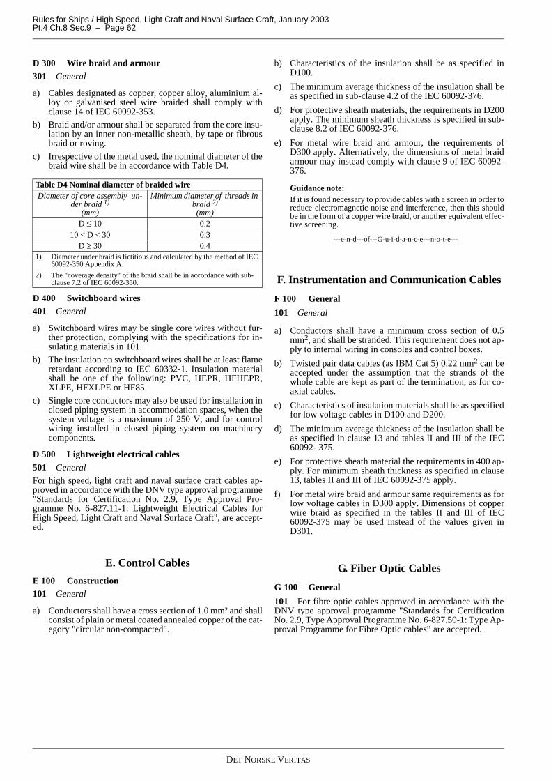
Rules for Ships / High Speed, Light Craft and Naval Surface Craft, January 2003Pt.4 Ch.8 Sec.9 – Page 62
D 300 Wire braid and armour301 General
a) Cables designated as copper, copper alloy, aluminium al-loy or galvanised steel wire braided shall comply withclause 14 of IEC 60092-353.
b) Braid and/or armour shall be separated from the core insu-lation by an inner non-metallic sheath, by tape or fibrousbraid or roving.
c) Irrespective of the metal used, the nominal diameter of thebraid wire shall be in accordance with Table D4.
D 400 Switchboard wires401 General
a) Switchboard wires may be single core wires without fur-ther protection, complying with the specifications for in-sulating materials in 101.
b) The insulation on switchboard wires shall be at least flameretardant according to IEC 60332-1. Insulation materialshall be one of the following: PVC, HEPR, HFHEPR,XLPE, HFXLPE or HF85.
c) Single core conductors may also be used for installation inclosed piping system in accommodation spaces, when thesystem voltage is a maximum of 250 V, and for controlwiring installed in closed piping system on machinerycomponents.
D 500 Lightweight electrical cables501 General
For high speed, light craft and naval surface craft cables ap-proved in accordance with the DNV type approval programme"Standards for Certification No. 2.9, Type Approval Pro-gramme No. 6-827.11-1: Lightweight Electrical Cables forHigh Speed, Light Craft and Naval Surface Craft", are accept-ed.
E. Control Cables
E 100 Construction101 General
a) Conductors shall have a cross section of 1.0 mm² and shallconsist of plain or metal coated annealed copper of the cat-egory "circular non-compacted".
b) Characteristics of the insulation shall be as specified inD100.
c) The minimum average thickness of the insulation shall beas specified in sub-clause 4.2 of the IEC 60092-376.
d) For protective sheath materials, the requirements in D200apply. The minimum sheath thickness is specified in sub-clause 8.2 of IEC 60092-376.
e) For metal wire braid and armour, the requirements ofD300 apply. Alternatively, the dimensions of metal braidarmour may instead comply with clause 9 of IEC 60092-376.
Guidance note:If it is found necessary to provide cables with a screen in order toreduce electromagnetic noise and interference, then this shouldbe in the form of a copper wire braid, or another equivalent effec-tive screening.
---e-n-d---of---G-u-i-d-a-n-c-e---n-o-t-e---
F. Instrumentation and Communication Cables
F 100 General
101 General
a) Conductors shall have a minimum cross section of 0.5mm2, and shall be stranded. This requirement does not ap-ply to internal wiring in consoles and control boxes.
b) Twisted pair data cables (as IBM Cat 5) 0.22 mm2 can beaccepted under the assumption that the strands of thewhole cable are kept as part of the termination, as for co-axial cables.
c) Characteristics of insulation materials shall be as specifiedfor low voltage cables in D100 and D200.
d) The minimum average thickness of the insulation shall beas specified in clause 13 and tables II and III of the IEC60092- 375.
e) For protective sheath material the requirements in 400 ap-ply. For minimum sheath thickness as specified in clause13, tables II and III of IEC 60092-375 apply.
f) For metal wire braid and armour same requirements as forlow voltage cables in D300 apply. Dimensions of copperwire braid as specified in the tables II and III of IEC60092-375 may be used instead of the values given inD301.
G. Fiber Optic Cables
G 100 General
101 For fibre optic cables approved in accordance with theDNV type approval programme "Standards for CertificationNo. 2.9, Type Approval Programme No. 6-827.50-1: Type Ap-proval Programme for Fibre Optic cables” are accepted.
Table D4 Nominal diameter of braided wireDiameter of core assembly un-
der braid 1)
(mm)
Minimum diameter of threads in braid 2)
(mm)D ≤ 10 0.2
10 < D < 30 0.3D ≥ 30 0.4
1) Diameter under braid is fictitious and calculated by the method of IEC 60092-350 Appendix A.
2) The "coverage density" of the braid shall be in accordance with sub-clause 7.2 of IEC 60092-350.
DET NORSKE VERITAS

Rules for Ships / High Speed, Light Craft and Naval Surface Craft, January 2003 Pt.4 Ch.8 Sec.10 – Page 63
SECTION 10INSTALLATION
A. General Requirements
A 100 General
101 General
Reference is made to other sections of this chapter, especiallySec.2 for requirements affecting location, arrangements, andinstallation of systems in an early project stage, and Sec.3 toSec.9 for requirements affecting the various equipment.
Equipment in hazardous areas shall be selected, located and in-stalled according to Sec.11.
102 References to standards
The requirements in this section are based upon IMO codesand regulations and the relevant IEC standards.
B. Equipment
B 100 Equipment location and arrangement
101 General
a) All electrical equipment shall be installed "electricallysafe". This is to prevent injury to personnel, when theequipment is handled or touched in the normal manner.(Interpretation of SOLAS Reg. II-1/45.1.3)
b) All electrical equipment shall be selected and installed soas to avoid EMC problems. Thus preventing disturbingemissions from equipment, or preventing equipment frombecoming disturbed and affecting its intended function(s).
c) Electrical equipment shall be placed in accessible loca-tions so that those parts, which require manual operation,are easily accessible.
d) Heat dissipating electrical equipment as for example light-ing fittings and heating elements, shall be located and in-stalled so that high temperature equipment parts do notdamage associated cables and wiring, or affect surround-ing material or equipment, and thus become a fire hazard.(Interpretation of SOLAS Reg. II-1/45.7)
e) Equipment shall be installed in such a manner that the cir-culation of air to and from the associated equipment or en-closures is not obstructed. The temperature of the coolinginlet air shall not exceed the ambient temperature forwhich the equipment is specified.
f) All equipment of smaller type (luminaires, socket outletsetc) shall be protected against mechanical damage eitherby safe location or by additional protection, if not of a rug-ged metallic construction.
g) Requirements for switchboard arrangement are given inSec.2 I200.
h) Requirements for rotating machinery arrangement are giv-en in Sec.2 I300.
i) See Sec.2 I for additional requirements for vessel arrange-ment.
102 Ventilation of spaces with electrical equipment
The ventilation shall be so arranged that water or condensationfrom the ventilator outlets does not reach any unprotected elec-trical equipment. See also Sec.2 I101.
103 High voltage switchgear and controlgear assemblies
Access to high voltage switchgear rooms and transformerrooms shall only be possible to instructed personnel.
Guidance note:Equipment located in machinery spaces may be considered as be-ing accessible only to instructed personnel. The same applies toequipment located in other compartments that are usually keptlocked, under the responsibility of the ship's officers.
---e-n-d---of---G-u-i-d-a-n-c-e---n-o-t-e---
104 Passage in front or behind switchgear
The passageways in front of and behind main and emergencyswitchboards shall be covered by mats or gratings of oil resist-ant insulating material, when the deck is made of a conductingmaterial.
105 Transformers
Liquid immersed transformers shall be installed in an area orspace with provisions for complete containment and drainageof liquid leakage.
106 Heating and cooking appliances
a) All combustible materials close to heating and cooking ap-pliances shall be protected by incombustible or insulatingmaterials.
b) Cabling and wiring (feeding) shall be suitable for theeventual higher temperature in the termination room ofsuch equipment.
c) Additional protection of IR–type of open heating elementsshall be installed, if necessary to guard against fire and ac-cidental touching.
B 200 Equipment enclosure, Ingress Protection201 Enclosure types in relation to location
Equipment enclosures shall comply with Table B1 in relationto the location of where it is installed and for high voltageequipment, see Sec.3 D501.
DET NORSKE VERITAS

Rules for Ships / High Speed, Light Craft and Naval Surface Craft, January 2003Pt.4 Ch.8 Sec.10 – Page 64
Table B1 Enclosure types in relation to locationLocation Switchgear
and trans-formers
Luminaires Rotating machines
Heating ap-pliances
Socket outlets
Miscellaneous such as switches and connection
boxes
Instrumenta-tion compo-
nents
Engine and boiler rooms
Above the floor IP 22 IP 22 IP 22 IP 22 IP 44 IP 44 IP 44Below the floor N IP 44 IP 44 IP 44 N IP 44 IP 56Dry control rooms and switchboard rooms
IP 21 1) IP 22 IP 22 IP 22 IP 22 IP 22 IP 22
Closed compart-ments for fuel oil and lubrication oil separators
IP 44 IP 44 IP 44 IP 44 N IP 44 IP 44
Fuel oil tanks 2) N N N N N N IP 68Ballast and other water tanks, bilge wells 2) N N IP 68 IP 68 N N IP 68
Ventilation ducts N N 13) IP 4413) N N N 13)
Deckhouses, forecastle spaces, steering gear compartments and similar spaces
IP 22 3) IP 22 IP 22 3) IP 22 IP 44 IP 44 IP44
Ballast pump rooms, columns be-low main deck and pontoons and similar rooms below the load line
IP 44 14) IP 44 IP 44 14) IP 44 IP 56 5) IP 56 5) IP 56 5)
Cargo holds 4) N IP 55 IP 44 N IP 56 5) IP 56 5) IP 56 5)
Open deck, keel ducts IP 56 IP 55 IP 56 6) IP 56 IP 56 5) IP 56 5) IP 56Battery rooms, paint stores, gas bottle stores or areas that may be hazardous due to the cargo or proc-esses onboard 7)
N EX 12) EX 12) EX 12) N EX 12) EX 12)
Dry accommodation spaces IP 20 IP 20 IP 20 IP 20 IP 20 IP 20 8) IP 22Bath rooms and showers N IP 44 11) N IP 44 N 9) IP 56 11) IP 56 11)
Galleys, laundries and similar rooms 10) IP 44 IP 44 IP 44 IP 44 IP 44 IP 44 IP 44
(N: Normally, not accepted for installation in this location.)
1) Switchboards in dry control rooms and switchboard rooms with IP 21 shall have a roof with eaves. If there is a chance of dripping water from piping, condensed water, etc. then a higher IP rating may be necessary.
2) For cable pipes and ducts through fuel oil and water tanks, see C703.
3) Such equipment shall be provided with heating elements for keeping it dry when not in use. The heating elements shall normally be automatically switched on when the equipment is switched off. Continuously connected heating elements may be accepted provided the maximum allowed temperatures are main-tained when the equipment is in operation.
4) For enclosures in cargo holds, placed so that they are liable to come into contact with the cargo or cargo handling gear, see 101. For truck battery charging arrangements, see Sec.2 I305. For electrical installations in cargo holds for dangerous goods, see Pt.5 Ch.11 Sec.2 B300 of the Rules for Classification of Ships. For special category spaces in passenger vessels and ferries see Solas Reg. II-2/37. For such cargoes, also national regulations apply. For vessels carrying cars with fuel in their tanks see Pt.3 Ch.3 sec.10 of the Rules for Classification of Ships.
5) IP 44 may be accepted, when placed in a box giving additional protection against ingress of water. Equipment for control and indication of watertight doors and hatches shall have watertightness based on the water pressure that may occur at the location of the component, if intrusion of water can affect the control or indication system.
6) Motors on open deck shall have ingress protection IP 56, and either:
— be naturally cooled, i.e. without external cooling fan— be vertically mounted and equipped with an additional steel hat preventing ingress of water or snow into any external ventilator— or be equipped with a signboard requiring that the motor shall only be used in port, and be provided with additional covers (e.g. tarpaulins) at sea.
7) For arrangement and connection of batteries, see Sec.2. For installations in paint stores, gas bottle stores or areas that may be hazardous due to the cargo or processes onboard, the requirements in Sec.11 shall be complied with.
8) Connection boxes may be accepted installed behind panels in dry accommodation spaces provided that they are accessible through a hinged panel or sim-ilar arrangement.
9) Socket outlets shall be so placed that they are not exposed to splash, e.g. from showers. Circuits for socket outlets in bathrooms shall either be fed from a double insulated transformer, or be equipped with earth fault protection with a maximum release current of 30 mA.
10) Stoves, ovens and similar equipment may be accepted with IP 22 when additionally protected against water splash by hose or washing of the floor.
11) Lower degree of protection may be accepted provided the equipment is not exposed to water splash.
12) Type of ingress protection shall be as for deckhouses. Minimum explosion group and temperature class shall be one of those specified in Table B2 (Some national regulations may limit the choice of type of protection).
13) Luminaires and instrumentation components may be accepted after special consideration. It shall be observed that a ventilation duct may be a hazardous area, depending upon the area classification at the ends of the duct.
14) Electric motors and starting transformers for side thrusters shall be equipped with heating elements for standstill heating.
DET NORSKE VERITAS

Rules for Ships / High Speed, Light Craft and Naval Surface Craft, January 2003 Pt.4 Ch.8 Sec.10 – Page 65
B 300 Batteries301 General
Battery installations are to comply with the requirements inSec.2 I regarding requirements for their location, compart-ments etc.
302 Materials
The following requirements apply to all stationary accumula-tor batteries:
a) Battery stands, boxes and lockers shall be fixed to the ves-sel's structure. The batteries shall be fixed or supported onthe shelves. Shelves and fixings shall be constructed towithstand the forces imparted from the batteries, duringheavy sea.
b) All materials used for the construction, including ventila-tion ducts and fans, shall be corrosion resistant or shall beprotected against corrosion by suitable painting, with con-sideration given to the type of electrolyte actually used.
c) The materials shall be at least flame retardant, except thatimpregnated wood can be used for the support of batterycells, and for battery boxes on deck.
d) Except when corrosion resistant materials are used, theshelves in battery rooms and lockers and the bottom of bat-tery boxes shall be covered with a lining of corrosion re-sistant material, having a minimum thickness of 1.5 mmand being carried up not less than 75 mm on all sides (e.g.lead sheath for lead and acid batteries, steel for alkalinebatteries). If the shelves in battery rooms and lockers areof corrosion resistant materials and the floor is not, eitherthe shelves or the floor shall be covered with such lining.
303 Testing
The following tests and inspections shall be performed beforebatteries are put into service:
— ventilation shall be verified, including natural ventilation— capacity tests, voltage measurements— alarms and monitoring functions.
304 Marking and signboards
See 503 for the requirements for marking and signboards, withrespect to battery installations.
B 400 Protective earthing and bonding of equipment401 General
a) Earth conductors shall normally be of copper. However,other suitable materials may be accepted if, for examplethe atmosphere is corrosive to copper.
b) The earth conductor's cross section shall be equivalent tothat of copper with regard to conductivity. Applicable ar-rangements and cross sections are given in Sec.2 Table J2.
c) The connection to the hull of earth conductors or equip-ment enclosure parts, which shall be earthed, shall bemade by corrosion resistant screws or clamps, with crosssection corresponding to the required cross section of earthgiven in Sec.2 J303.
d) Earthing screws and clamps shall not be used for otherpurposes. Suitable star washers and conductor terminalsshall be used, so that a reliable contact is ensured.
e) Metal enclosures or other exposed conductive parts beinga part of electrical equipment shall be earthed by fixing themetal enclosure or exposed parts in firm (conductive) con-tact to the hull (main earth potential) or by a separate earthconductor.
f) For distribution systems with neutral earthed through animpedance or direct terminated and distributed neutral(TN-S), protective earthing (PE) shall be carried out byconnecting exposed parts direct to feeding switchboardmain PE, via an earth conductor in the supply cable.
g) Portable equipment shall always be earthed by an earthconductor contained in the flexible supply cable.
h) All extraneous conductive parts supporting electricalequipment and cable support systems, that is ladders, pipesand ducts for electrical cables, are considered to be in firmelectrical contact with the hull as long as elements arewelded or mechanically attached (metal to metal withoutpaint or coating) with a star washer, thereby ensuring afirm conductive contact. If firm electrical contact is notachieved, the parts shall be bonded by a separate copperconductor between extraneous parts and the hull.
i) Additional precautions shall be applied regarding earthingof portable electrical equipment for use in confined or ex-ceptionally damp spaces where particular risks due to ex-posure and conductivity may exist.
j) High voltage metal enclosures and the steel hull shall beconnected by a separate earth conductor. The enclosuresfixing device shall not be the sole earthing connection ofthe enclosure.
k) If a separate earthing conductor is chosen for equipment,then the connection of the separate earth conductor to thehull, (safe earth potential) shall be made in an accessibleposition. The conductor shall be terminated by a pressuretype cable lug onto a corrosion protected bolt, which shallbe secured against loosening. Other suitable terminatingsystems for direct receipt of the conductor may be consid-ered.
Guidance note:
Additional precautions in i) might be: The equipment having ex-tra safe low voltage, or for ordinary 230 V equipment, by using asafety transformer system or by having an earth fault switch ofmaximum 30 mA in front of the circuit.
---e-n-d---of---G-u-i-d-a-n-c-e---n-o-t-e---
402 Exceptions to the earthing or bonding requirements
a) If one of the following conditions is fulfilled, the require-ments in 401 may be omitted:
— equipment supplied at a voltage not exceeding 50 VD.C. or A.C. between conductors. Auto-transformersshall not be used for the purpose of achieving thisvoltage
— equipment supplied at a voltage not exceeding 250 Vby safety isolating transformer and the transformer issupplying only one consumer device
— equipment constructed in accordance with the princi-ple of double insulation.
b) Parts fixed to non-conductive materials, and separatedfrom current carrying parts and from earthed parts in sucha way that they cannot become live under normal or elec-trical fault conditions.
c) Bearing housings which are insulated in order to preventcirculating currents.
d) Cable clips do not need protective earthing.
Table B2 Minimum explosion groups and temperature classes for different locationsLocation Explosion group Temperature
classBattery rooms II C T1Stores for welding gas bottles II C T2Lamp rooms and paint stores II B T3
DET NORSKE VERITAS

Rules for Ships / High Speed, Light Craft and Naval Surface Craft, January 2003Pt.4 Ch.8 Sec.10 – Page 66
403 Dimension of protective earth and bonding conductors
For dimension of protective earth and bonding conductors, seeSec.2.
B 500 Equipment termination, disconnection, marking
501 General
All equipment shall be installed and terminated in accordancewith manufacturer's instructions to ensure that correct func-tions and safe properties are contained.
502 Multipole disconnection of equipment circuits
a) All electric circuits connecting final consumers shall beprovided with multipole disconnection device.
b) The multipole device shall be an on load switching device.MCBs with accessible on and off levers, intended for loadswitching, may be accepted.
c) All consumers other than motors shall be controlled by atleast a multipole switchgear, except that single poleswitches can be used for luminaires or space heaters in dryaccommodation spaces where floor covering, bulkheadand ceiling linings are of insulating material.
Guidance note:Multipole disconnection means that all active poles are discon-nected simultaneously. However, any N-conductor is not regard-ed as an active pole, and need not be disconnected.
---e-n-d---of---G-u-i-d-a-n-c-e---n-o-t-e---
503 Signboards for equipment
a) Labels (nameplates) of flame retardant material, bearingclear and indelible indications, shall be so placed that allequipment necessary for the operation can be easily iden-tified. All labels shall be permanently fixed.
b) All equipment shall, if necessary, be marked so as to en-sure correct use. Signboards giving guidance for safe use,or conditions for use, shall be fitted, if necessary, in orderto avoid inadvertent or dangerous operation of equipmentand or systems.
c) "High voltage" warning signboards are required on allhigh voltage equipment.
d) High voltage cables shall be suitably marked with "highvoltage" warning signboards, at least for every 20 m, sothat a signboard is always visible.
e) On rotating machines, on deck, that are not naturallycooled, i.e. with external cooling fan, a signboard shall befitted on the machines requiring that the machines shallonly be used in port and be provided with additional cov-ers (e.g. tarpaulins) when at sea. See Table B1, note 6.
f) At each socket outlet for portable appliances where 1000V is accepted, (e.g. welding transformers, refrigeratedcontainers etc., which are not hand-held during operation)an additional warning sign shall be fitted, with the text:DANGER (maximum voltage) V A.C. ONLY FOR CON-NECTION OF ....(type of equipment)....
g) Signboards shall be fitted in battery rooms and on doors orcovers of boxes or lockers, warning against risk for explo-sive gas, smoking and the use of naked lights.
h) All batteries shall be provided with labels (nameplates) offlame retardant material, giving information on the appli-cation for which the battery is intended, make, type, volt-age and capacity. Instructions shall be fitted either at thebattery or at the charging device, giving information onmaintenance and charging.
i) Battery systems above 50 V shall be marked with specialvisible warning signboard, i.e. “Warning xxx voltage”.
B 600 Neon lighting
601 General
a) Neon tubes for voltage above 1000 V, 50 Hz, shall be in-stalled at least 2.5 m above the floor.
b) Each circuit shall have circuit protection rated at maxi-mum 16 A.
c) The on and off switch shall be clearly marked. The switchis not accepted on the secondary side of the transformer.
d) Cables and wires shall have braiding, armour or be fittedin an earthed pipe.
C. Cables
C 100 General
101 General
a) Cable sizing with respect to current carrying capacity andshort circuit withstand capabilities shall comply with therequirements in Sec.2.
b) For requirements for cable construction and materials, seeSec.9.
c) A.C. cabling shall be carried out, as far as practicable, intwin or multicore cables.
d) For installations in connection with hazardous areas, re-quirements for selection of cables, cable routing and fix-ing, see Sec.11.
Guidance note:Use of cables with low emission of smoke in case of a fire, shouldbe considered for all indoor installations. In areas where equip-ment sensitive to corrosion is installed or kept, use of Halogenfree cables should be considered to avoid corrosive smoke in caseof a fire, as far as is practicable.
---e-n-d---of---G-u-i-d-a-n-c-e---n-o-t-e---
102 Painting of cables
Electrical cables may be coated or painted, but this shall notadversely affect the mechanical, chemical or fire resistantcharacteristics of the sheath.
Guidance note:The Society has experience from cables damaged by two compo-nent epoxy painting bonding to the sheath material.Unless the yard has experience with the combination of paint andcable type used, the manufacturers should be consulted by theyard.
---e-n-d---of---G-u-i-d-a-n-c-e---n-o-t-e---
103 Cable sheath
Cables with metal sheath or braid or armour shall be providedwith an outer sheath for corrosion protection when installed ondeck, through cargo holds, in pump rooms, keel ducts and sim-ilar wet or corrosive spaces. This also applies to cables carriedin pipes in such spaces, and to cables that are carried in pipesthrough water or fuel oil tanks.
Guidance note:Any additional armour provided, but not required by the rules,does not need a protective outer sheath as long as the protectivearmour is not used as a conductor for protective earthing.
---e-n-d---of---G-u-i-d-a-n-c-e---n-o-t-e---
104 Corrosion protection
Sheath or braid or armour of lead, bronze or copper shall notbe installed in contact with aluminium alloy structures, exceptin dry accommodation spaces.
DET NORSKE VERITAS

Rules for Ships / High Speed, Light Craft and Naval Surface Craft, January 2003 Pt.4 Ch.8 Sec.10 – Page 67
105 Flexible cables
The use of flexible cables shall be limited to applicationswhere flexibility is necessary, and the lengths of such flexiblecables shall be kept as short as practicable. Special require-ments may be made to the type, installation and protection offlexible cables, depending upon the application.
106 High voltage cables
Installation of high voltage cables in accommodation spaces isnot permitted unless required by the application. The necessityfor special protection shall be evaluated when high voltage ca-bles are installed in accommodation spaces, for prevention ofharmful effects to personnel from cable short circuits, andstrong electromagnetic fields.
107 Fibre optic cables
Tensile stress applied to fibre optic cables for any reason dur-ing the installation period or during normal operation shall notexceed the maximum allowed value stated by the manufactur-er.
C 200 Routing of cables
201 General
For more requirements regarding the routing of cables, seeSec.2 I500.
202 Segregation of low and high voltage cables
a) Low voltage power cables shall not be bunched togetherwith, or run through the same pipes as, or be terminated inthe same box as, cables for high voltage.
b) High voltage cables shall be separated from low voltagecables and control cables by at least 300 mm unless me-chanically separated by earthed metal partitions or pipes.
203 Segregation of power cables and cables for control cir-cuits
a) Unscreened cables for sensitive control or signal circuits(below 50 V) shall not be run in the same bunch or pipe ascables for power circuits, (above 50 V). This is in order toavoid interference from the power circuit.
b) For segregation of cables in installations for hazardous ar-eas, see Sec.11 D200.
Guidance note:Crossovers or installation of power cables and control cables be-side each other are generally not considered a problem if signalcable is screened.A distance of 50 mm between power and unbraided or un-screened control cables on a cable tray is considered acceptable.
---e-n-d---of---G-u-i-d-a-n-c-e---n-o-t-e---
204 Special precautions for single core cables
When the use of single core cables is necessary for circuitshaving a normal current of 20 A and above the following ap-ply:
a) The cables shall be non- armoured or braided or the ar-mour or braiding material shall be of a non-magnetic type.
b) The non-magnetic armour or braiding shall be earthed atone end, only.
c) Conductors belonging to the same circuit shall be con-tained within the same pipe, conduit or trunking, clampsthat fix them shall include all phases.
d) The phases shall be laid as close as possible and preferablyin a triangular formation.
e) Magnetic material shall not be used between single corecables for one consumer. All phases belonging to the samecircuit shall be run together in a common gland or bulk-
head penetration (MCT), unless the penetration system isof non-magnetic material. Unless installed in a triangularformation, the distance between the cables and magneticmaterial shall be 75 mm.
f) Circuits with several single core cables for each phase(forming groups) shall follow the same route and have thesame cross sectional area.
g) The cables belonging to the same phase shall as far aspracticable alternate with those of the other phases, so thatan unequal division of current is avoided.
h) For fixing of single core cables, see C506.
205 Accessible cable runs
a) Cable runs shall be accessible, except for cables carried inpipes.
b) Cable runs shall be accessible for later inspection. Freedistance above trays, and cables laid on trays, shall be aminimum of 100 mm. Distance between cable trays, or to-wards adjacent structures shall be a minimum of 50 mm.
c) When cable runs are carried behind wall lining in accom-modation spaces (except when carried in pipes), the panelsshall be hinged or fixed for example by screws, so thatthey can be removed for inspection without damaging thecable or the bulkhead.
d) Exceptions can be made for cables to light fittings, switch-es, socket outlets etc. in dry accommodation spaces, whenthe deckhead and bulkhead constructions are made of in-combustible materials.
C 300 Penetrations of bulkhead and decks301 General
a) Penetrations of watertight bulkheads and decks shall becarried out either with a separate gland for each cable, orwith boxes or pipes filled with a suitable flame retardantpacking or moulded material, in order to ensure the integ-rity of the watertightness of the bulkhead or deck. The in-stallation shall be in accordance with the manufacturers'installation instructions.
b) Penetrations of a recognised make shall be used where fireresisting separation is needed.
Guidance note:Penetrations of watertight bulkheads should be placed as high aspracticable.
---e-n-d---of---G-u-i-d-a-n-c-e---n-o-t-e---
302 Thermal insulation
Cable runs shall not be laid in or covered with thermal insula-tion (e.g. through refrigerated cargo holds), but may crossthrough such insulation.
303 Hot oil pipes near to penetrations
The distance from cable penetrations to flanges of steam or hotoil pipes shall not be less than 300 mm for steam or hot oilpipes with diameter D ≤ 75 mm, and not less than 450 mm forlarger pipes.
304 Chafing
Penetrations of bulkheads and decks shall be such that the ca-bles are not chafed. (Interpretation of SOLAS Reg. II-1/45.5.5)
305 Mechanical support of penetrations
The cable shall have mechanical fixing on both sides of a bulk-head penetration.
C 400 Fire protection measures401 General
The cable installation shall be protected against fire, fire
DET NORSKE VERITAS

Rules for Ships / High Speed, Light Craft and Naval Surface Craft, January 2003Pt.4 Ch.8 Sec.10 – Page 68
spreading, thermal, mechanical, corrosive and strain damage.(Interpretation of SOLAS Reg. II-1/45.5.2)
402 Flammable materials
Cables shall not be installed in contact with flammable materi-als such as wooden bulkheads, when the conductor tempera-ture exceeds 95°C at full load, at the actual ambienttemperature.
403 Precautions against fire spreading in cable bunches
Cables that are installed in bunches shall have been tested inaccordance with a recognised fire test for cables installed inbunches, such as the test specified in IEC 60332-3, or be pro-vided with protection according to 404 and 405.
Guidance note:A cable bunch is defined as five or more cables laid close togeth-er in trunks from machinery spaces and in spaces with a high riskof fire, and more than 10 cables in other areas.
---e-n-d---of---G-u-i-d-a-n-c-e---n-o-t-e---
404 Cable bunches not complying with IEC 60332-3 or otherrecognised standard fire spread test.
a) Cable bunches, not complying with flame retardant prop-erties according to IEC 60332-3, shall be provided withfire stops having at least class B-0 penetration propertiesat the following locations:
— cable entries at the main and emergency switchboards— where cables enter engine control rooms— cable entries at centralised control panels for propul-
sion machinery and essential auxiliaries— at each end of totally enclosed cable trunks— at every second deck or approximately every 6 m for
vertical runs— at every 14 m for horizontal runs, except that in the
cargo area fire stops need only be fitted at the bound-aries of the space.
Additional fire stops need not be fitted inside totally en-closed cable trunks.
b) Alternatively, for additional fire stops, fire protective coat-ing may be applied to the cable bunch according to the fol-lowing:
— to the entire length of vertical runs— to at least 1 m in every 14 m for horizontal runs.
405 Fire resistance of penetrations
Where "A" or "B" class bulkheads or decks are penetrated forthe passage of electrical cables, arrangements shall be made toensure that the fire resistance of the bulkheads or decks, is notimpaired.
406 Fire resistance cables
For requirements to fire resistance cable, see Sec.2 J 102.
C 500 Support and fixing of cables and cable runs501 General
a) Cable ladders, trays and cable pipes shall not be used forcarrying water, oil or steam pipes. Exemptions may beconsidered in each case.
b) For installations in connection with hazardous areas, re-quirements for selection of cables, cable routing and fix-ing, see Sec.11.
502 Cable ladder or tray material and mechanical require-ments
a) Cable ladders and trays with their fixing devices shall bemade of corrosion resistant steel or type tested non-metal-lic materials with equal properties.
b) When fixed to aluminium structures, aluminium alloy ca-ble ladders and trays may be used. Other materials may beaccepted upon special consideration.
c) Cables with IEC 60228 Class 5 conductors shall be in-stalled on continuous cable trays (vented or non-vented)such as to prevent undue sag, and if horizontal, on the topof the tray giving support to the cable.
d) The load on the cable trays or protective casings is to bewithin the Safe Working Load (SWL). The support spac-ing is not to be greater than manufacturer’s recommenda-tion nor in excess of spacing at the SWL test. In general thespacing is not to exceed 2 m.
e) Cable trays or protective casings made of plastic materialsare to be supplemented by metallic fixing and straps suchthat in event of a fire they, and the cable affixed, are pre-vented from falling and causing an injury to personneland/or an obstruction to any escape route.
Guidance note:The term "cable ladder" includes support brackets. The term "ca-ble tray" means constructions being formed by continuous trayplates or structural steel.
---e-n-d---of---G-u-i-d-a-n-c-e---n-o-t-e---
503 Mechanical protection of cables and cable runs
a) Cables shall be so installed that they are not likely to suffermechanical damage. If necessary, they shall be protectedby providing the cable runs with covers of plates, profilesor grids, or by carrying the cables in pipes.
b) Below the floor in engine and boiler rooms and similarspaces, cables that may be exposed to mechanical damageduring maintenance work in the space, shall be protectedin accordance with a).
c) All cables that may be exposed to mechanical damage,shall be protected by covers of steel plates, steel grids orprofiles of at least 4 mm thickness, or by being carried insteel pipes, e.g. on weather decks in cargo hold areas, andthrough cargo holds.
Guidance note:As an alternative the covers can be made of perforated steelplates or grids with mesh opening maximum 25 mm, having atleast the same impact strength as a 4 mm steel plate. Exemptionscan be accepted when the location of the cable run is such that inall probability cargo or cargo handling gear cannot come intocontact with the cable run. When cable runs are fixed to alumin-ium structures, aluminium may be used instead of steel.
---e-n-d---of---G-u-i-d-a-n-c-e---n-o-t-e---
504 Cable bends
a) The internal radius of low voltage cable bends, which arenot subjected to movement by expansion, shall be in ac-cordance with the manufacturers' recommendation, butnormally, not less than given in Table C2.
b) The minimum internal bending radius for high voltage ca-bles shall be in accordance with the manufacturers' recom-mendations.
DET NORSKE VERITAS
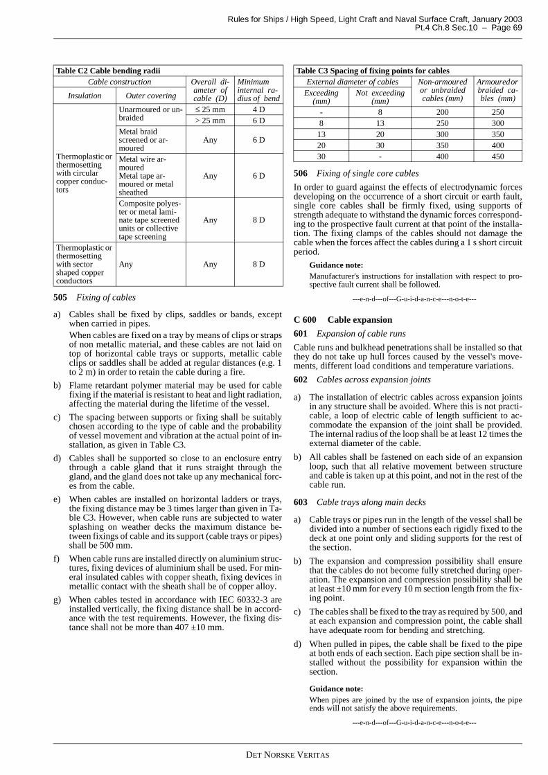
Rules for Ships / High Speed, Light Craft and Naval Surface Craft, January 2003 Pt.4 Ch.8 Sec.10 – Page 69
505 Fixing of cables
a) Cables shall be fixed by clips, saddles or bands, exceptwhen carried in pipes.When cables are fixed on a tray by means of clips or strapsof non metallic material, and these cables are not laid ontop of horizontal cable trays or supports, metallic cableclips or saddles shall be added at regular distances (e.g. 1to 2 m) in order to retain the cable during a fire.
b) Flame retardant polymer material may be used for cablefixing if the material is resistant to heat and light radiation,affecting the material during the lifetime of the vessel.
c) The spacing between supports or fixing shall be suitablychosen according to the type of cable and the probabilityof vessel movement and vibration at the actual point of in-stallation, as given in Table C3.
d) Cables shall be supported so close to an enclosure entrythrough a cable gland that it runs straight through thegland, and the gland does not take up any mechanical forc-es from the cable.
e) When cables are installed on horizontal ladders or trays,the fixing distance may be 3 times larger than given in Ta-ble C3. However, when cable runs are subjected to watersplashing on weather decks the maximum distance be-tween fixings of cable and its support (cable trays or pipes)shall be 500 mm.
f) When cable runs are installed directly on aluminium struc-tures, fixing devices of aluminium shall be used. For min-eral insulated cables with copper sheath, fixing devices inmetallic contact with the sheath shall be of copper alloy.
g) When cables tested in accordance with IEC 60332-3 areinstalled vertically, the fixing distance shall be in accord-ance with the test requirements. However, the fixing dis-tance shall not be more than 407 ±10 mm.
506 Fixing of single core cables
In order to guard against the effects of electrodynamic forcesdeveloping on the occurrence of a short circuit or earth fault,single core cables shall be firmly fixed, using supports ofstrength adequate to withstand the dynamic forces correspond-ing to the prospective fault current at that point of the installa-tion. The fixing clamps of the cables should not damage thecable when the forces affect the cables during a 1 s short circuitperiod.
Guidance note:Manufacturer's instructions for installation with respect to pro-spective fault current shall be followed.
---e-n-d---of---G-u-i-d-a-n-c-e---n-o-t-e---
C 600 Cable expansion
601 Expansion of cable runs
Cable runs and bulkhead penetrations shall be installed so thatthey do not take up hull forces caused by the vessel's move-ments, different load conditions and temperature variations.
602 Cables across expansion joints
a) The installation of electric cables across expansion jointsin any structure shall be avoided. Where this is not practi-cable, a loop of electric cable of length sufficient to ac-commodate the expansion of the joint shall be provided.The internal radius of the loop shall be at least 12 times theexternal diameter of the cable.
b) All cables shall be fastened on each side of an expansionloop, such that all relative movement between structureand cable is taken up at this point, and not in the rest of thecable run.
603 Cable trays along main decks
a) Cable trays or pipes run in the length of the vessel shall bedivided into a number of sections each rigidly fixed to thedeck at one point only and sliding supports for the rest ofthe section.
b) The expansion and compression possibility shall ensurethat the cables do not become fully stretched during oper-ation. The expansion and compression possibility shall beat least ±10 mm for every 10 m section length from the fix-ing point.
c) The cables shall be fixed to the tray as required by 500, andat each expansion and compression point, the cable shallhave adequate room for bending and stretching.
d) When pulled in pipes, the cable shall be fixed to the pipeat both ends of each section. Each pipe section shall be in-stalled without the possibility for expansion within thesection.
Guidance note:When pipes are joined by the use of expansion joints, the pipeends will not satisfy the above requirements.
---e-n-d---of---G-u-i-d-a-n-c-e---n-o-t-e---
Table C2 Cable bending radiiCable construction Overall di-
ameter of cable (D)
Minimum internal ra-dius of bendInsulation Outer covering
Thermoplastic or thermosetting with circular copper conduc-tors
Unarmoured or un-braided
≤ 25 mm 4 D> 25 mm 6 D
Metal braid screened or ar-moured
Any 6 D
Metal wire ar-mouredMetal tape ar-moured or metal sheathed
Any 6 D
Composite polyes-ter or metal lami-nate tape screened units or collective tape screening
Any 8 D
Thermoplastic or thermosetting with sector shaped copper conductors
Any Any 8 D
Table C3 Spacing of fixing points for cablesExternal diameter of cables Non-armoured
or unbraided cables (mm)
Armoured or braided ca-bles (mm)
Exceeding (mm)
Not exceeding (mm)
- 8 200 2508 13 250 300
13 20 300 35020 30 350 40030 - 400 450
DET NORSKE VERITAS
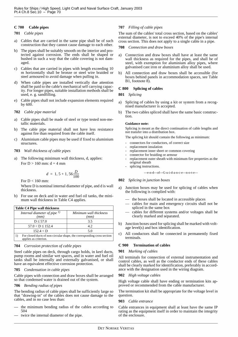
Rules for Ships / High Speed, Light Craft and Naval Surface Craft, January 2003Pt.4 Ch.8 Sec.10 – Page 70
C 700 Cable pipes
701 Cable pipes
a) Cables that are carried in the same pipe shall be of suchconstruction that they cannot cause damage to each other.
b) The pipes shall be suitably smooth on the interior and pro-tected against corrosion. The ends shall be shaped orbushed in such a way that the cable covering is not dam-aged.
c) Cables that are carried in pipes with length exceeding 10m horizontally shall be bronze or steel wire braided orsteel armoured to avoid damage when pulling in.
d) When cable pipes are installed vertically due attentionshall be paid to the cable's mechanical self carrying capac-ity. For longer pipes, suitable installation methods shall beused, e. g. sandfilling.
e) Cable pipes shall not include expansion elements requiredby 600.
702 Cable pipe material
a) Cable pipes shall be made of steel or type tested non-me-tallic materials.
b) The cable pipe material shall not have less resistanceagainst fire than required from the cable itself.
c) Aluminium cable pipes may be used if fixed to aluminiumstructures.
703 Wall thickness of cable pipes
a) The following minimum wall thickness, d, applies:For D > 160 mm: d = 4 mm
For D < 160 mm:Where D is nominal internal diameter of pipe, and d is wallthickness.
b) For use on deck and in water and fuel oil tanks, the mini-mum wall thickness in Table C4 applies.
704 Corrosion protection of cable pipes
Steel cable pipes on deck, through cargo holds, in keel ducts,pump rooms and similar wet spaces, and in water and fuel oiltanks shall be internally and externally galvanised, or shallhave an equivalent effective corrosion protection.
705 Condensation in cable pipes
Cable pipes with connection and draw boxes shall be arrangedso that condensed water is drained out of the system.
706 Bending radius of pipes
The bending radius of cable pipes shall be sufficiently large sothat "drawing-in" of the cables does not cause damage to thecables, and in no case less than:
— the minimum bending radius of the cables according to504
— twice the internal diameter of the pipe.
707 Filling of cable pipes
The sum of the cables' total cross section, based on the cables'external diameter, is not to exceed 40% of the pipe's internalcross section. This does not apply to a single cable in a pipe.
708 Connection and draw boxes
a) Connection and draw boxes shall have at least the samewall thickness as required for the pipes, and shall be ofsteel, with exemption for aluminium alloy pipes, wheregalvanised cast iron or aluminium alloy shall be used.
b) All connection and draw boxes shall be accessible (forboxes behind panels in accommodation spaces, see TableB1, footnote 8).
C 800 Splicing of cables
801 Splicing
a) Splicing of cables by using a kit or system from a recog-nised manufacturer is accepted.
b) The two cables spliced shall have the same basic construc-tion.
Guidance note:Splicing is meant as the direct continuation of cable lengths andnot transfer into a distribution box.
The splicing kit should contain the following as minimum:
- connectors for conductors, of correct size- replacement insulation- replacement inner sheet or common covering- connector for braiding or armour- replacement outer sheath with minimum fire properties as the
original sheath- splicing instructions.
---e-n-d---of---G-u-i-d-a-n-c-e---n-o-t-e---
802 Splicing in junction boxes
a) Junction boxes may be used for splicing of cables whenthe following is complied with:
— the boxes shall be located in accessible places— cables for main and emergency circuits shall not be
spliced in the same box— cables for different systems and/or voltages shall be
clearly marked and separated.
b) Junction boxes used for splicing shall be marked with volt-age level(s) and box identification.
c) All conductors shall be connected in permanently fixedterminals.
C 900 Termination of cables
901 Marking of cables
All terminals for connection of external instrumentation andcontrol cables, as well as the conductor ends of these cablesshall be clearly marked for identification, preferably in accord-ance with the designation used in the wiring diagram.
902 High voltage cables
High voltage cable shall have ending or termination kits ap-proved or recommended from the cable manufacturer.
The termination kit shall be appropriate for the voltage level inquestion.
903 Cable entrance
Cable entrances in equipment shall at least have the same IPrating as the equipment itself in order to maintain the integrityof the enclosure.
Table C4 Pipe wall thicknessInternal diameter of pipe 1)
(mm)Minimum wall thickness
(mm)D ≤ 57.0 3.5
57.0 < D ≤ 152.4 4.2152.4 < D 5.0
1) For closed ducts of non-circular shape, the corresponding cross section applies as criterion.
d 1 5 1 56D
100---------,+,=
DET NORSKE VERITAS
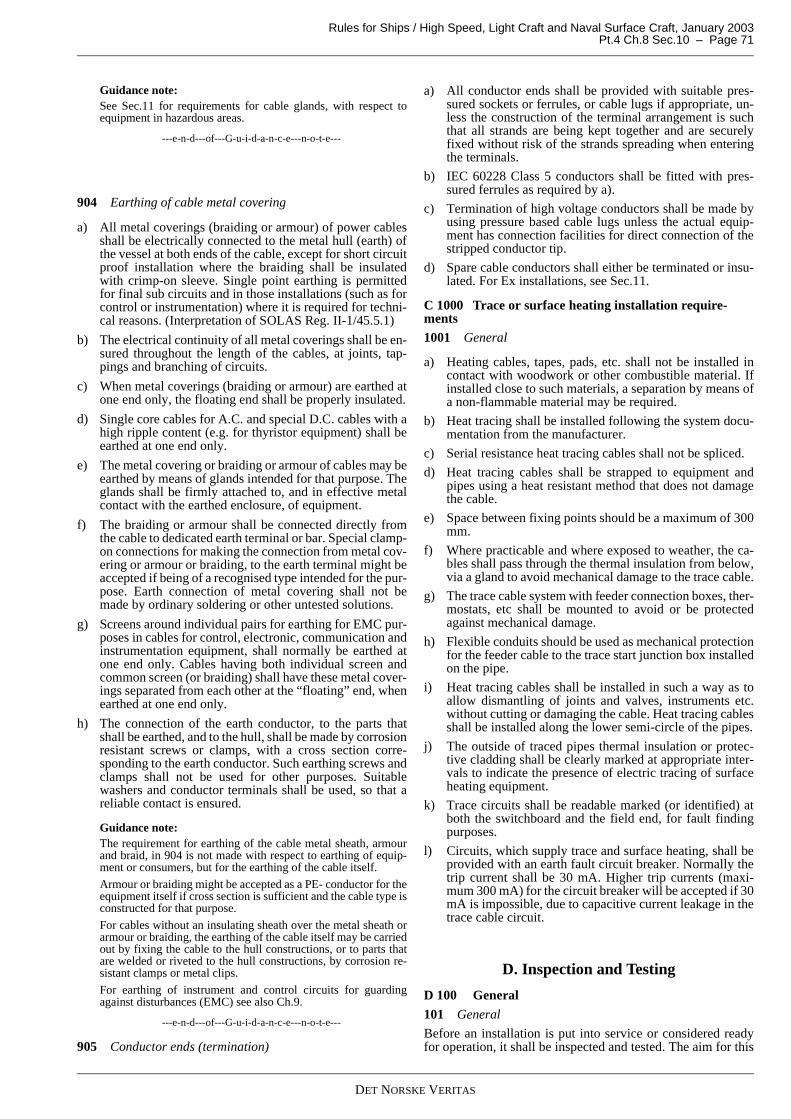
Rules for Ships / High Speed, Light Craft and Naval Surface Craft, January 2003 Pt.4 Ch.8 Sec.10 – Page 71
Guidance note:See Sec.11 for requirements for cable glands, with respect toequipment in hazardous areas.
---e-n-d---of---G-u-i-d-a-n-c-e---n-o-t-e---
904 Earthing of cable metal covering
a) All metal coverings (braiding or armour) of power cablesshall be electrically connected to the metal hull (earth) ofthe vessel at both ends of the cable, except for short circuitproof installation where the braiding shall be insulatedwith crimp-on sleeve. Single point earthing is permittedfor final sub circuits and in those installations (such as forcontrol or instrumentation) where it is required for techni-cal reasons. (Interpretation of SOLAS Reg. II-1/45.5.1)
b) The electrical continuity of all metal coverings shall be en-sured throughout the length of the cables, at joints, tap-pings and branching of circuits.
c) When metal coverings (braiding or armour) are earthed atone end only, the floating end shall be properly insulated.
d) Single core cables for A.C. and special D.C. cables with ahigh ripple content (e.g. for thyristor equipment) shall beearthed at one end only.
e) The metal covering or braiding or armour of cables may beearthed by means of glands intended for that purpose. Theglands shall be firmly attached to, and in effective metalcontact with the earthed enclosure, of equipment.
f) The braiding or armour shall be connected directly fromthe cable to dedicated earth terminal or bar. Special clamp-on connections for making the connection from metal cov-ering or armour or braiding, to the earth terminal might beaccepted if being of a recognised type intended for the pur-pose. Earth connection of metal covering shall not bemade by ordinary soldering or other untested solutions.
g) Screens around individual pairs for earthing for EMC pur-poses in cables for control, electronic, communication andinstrumentation equipment, shall normally be earthed atone end only. Cables having both individual screen andcommon screen (or braiding) shall have these metal cover-ings separated from each other at the “floating” end, whenearthed at one end only.
h) The connection of the earth conductor, to the parts thatshall be earthed, and to the hull, shall be made by corrosionresistant screws or clamps, with a cross section corre-sponding to the earth conductor. Such earthing screws andclamps shall not be used for other purposes. Suitablewashers and conductor terminals shall be used, so that areliable contact is ensured.
Guidance note:The requirement for earthing of the cable metal sheath, armourand braid, in 904 is not made with respect to earthing of equip-ment or consumers, but for the earthing of the cable itself.
Armour or braiding might be accepted as a PE- conductor for theequipment itself if cross section is sufficient and the cable type isconstructed for that purpose.
For cables without an insulating sheath over the metal sheath orarmour or braiding, the earthing of the cable itself may be carriedout by fixing the cable to the hull constructions, or to parts thatare welded or riveted to the hull constructions, by corrosion re-sistant clamps or metal clips.
For earthing of instrument and control circuits for guardingagainst disturbances (EMC) see also Ch.9.
---e-n-d---of---G-u-i-d-a-n-c-e---n-o-t-e---
905 Conductor ends (termination)
a) All conductor ends shall be provided with suitable pres-sured sockets or ferrules, or cable lugs if appropriate, un-less the construction of the terminal arrangement is suchthat all strands are being kept together and are securelyfixed without risk of the strands spreading when enteringthe terminals.
b) IEC 60228 Class 5 conductors shall be fitted with pres-sured ferrules as required by a).
c) Termination of high voltage conductors shall be made byusing pressure based cable lugs unless the actual equip-ment has connection facilities for direct connection of thestripped conductor tip.
d) Spare cable conductors shall either be terminated or insu-lated. For Ex installations, see Sec.11.
C 1000 Trace or surface heating installation require-ments1001 General
a) Heating cables, tapes, pads, etc. shall not be installed incontact with woodwork or other combustible material. Ifinstalled close to such materials, a separation by means ofa non-flammable material may be required.
b) Heat tracing shall be installed following the system docu-mentation from the manufacturer.
c) Serial resistance heat tracing cables shall not be spliced.
d) Heat tracing cables shall be strapped to equipment andpipes using a heat resistant method that does not damagethe cable.
e) Space between fixing points should be a maximum of 300mm.
f) Where practicable and where exposed to weather, the ca-bles shall pass through the thermal insulation from below,via a gland to avoid mechanical damage to the trace cable.
g) The trace cable system with feeder connection boxes, ther-mostats, etc shall be mounted to avoid or be protectedagainst mechanical damage.
h) Flexible conduits should be used as mechanical protectionfor the feeder cable to the trace start junction box installedon the pipe.
i) Heat tracing cables shall be installed in such a way as toallow dismantling of joints and valves, instruments etc.without cutting or damaging the cable. Heat tracing cablesshall be installed along the lower semi-circle of the pipes.
j) The outside of traced pipes thermal insulation or protec-tive cladding shall be clearly marked at appropriate inter-vals to indicate the presence of electric tracing of surfaceheating equipment.
k) Trace circuits shall be readable marked (or identified) atboth the switchboard and the field end, for fault findingpurposes.
l) Circuits, which supply trace and surface heating, shall beprovided with an earth fault circuit breaker. Normally thetrip current shall be 30 mA. Higher trip currents (maxi-mum 300 mA) for the circuit breaker will be accepted if 30mA is impossible, due to capacitive current leakage in thetrace cable circuit.
D. Inspection and Testing
D 100 General
101 General
Before an installation is put into service or considered readyfor operation, it shall be inspected and tested. The aim for this
DET NORSKE VERITAS
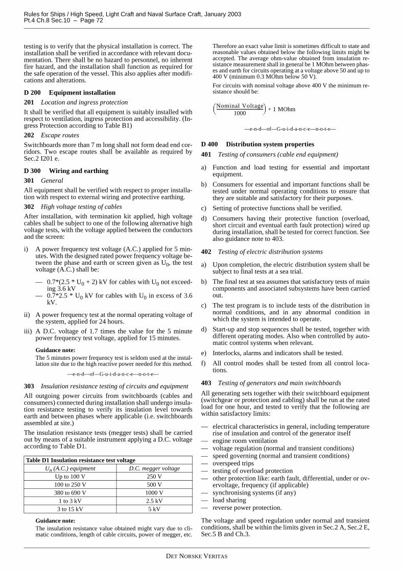
Rules for Ships / High Speed, Light Craft and Naval Surface Craft, January 2003Pt.4 Ch.8 Sec.10 – Page 72
testing is to verify that the physical installation is correct. Theinstallation shall be verified in accordance with relevant docu-mentation. There shall be no hazard to personnel, no inherentfire hazard, and the installation shall function as required forthe safe operation of the vessel. This also applies after modifi-cations and alterations.
D 200 Equipment installation201 Location and ingress protection
It shall be verified that all equipment is suitably installed withrespect to ventilation, ingress protection and accessibility. (In-gress Protection according to Table B1)
202 Escape routes
Switchboards more than 7 m long shall not form dead end cor-ridors. Two escape routes shall be available as required bySec.2 I201 e.
D 300 Wiring and earthing301 General
All equipment shall be verified with respect to proper installa-tion with respect to external wiring and protective earthing.
302 High voltage testing of cables
After installation, with termination kit applied, high voltagecables shall be subject to one of the following alternative highvoltage tests, with the voltage applied between the conductorsand the screen:
i) A power frequency test voltage (A.C.) applied for 5 min-utes. With the designed rated power frequency voltage be-tween the phase and earth or screen given as U0, the testvoltage (A.C.) shall be:
— 0.7*(2.5 * U0 + 2) kV for cables with U0 not exceed-ing 3.6 kV
— 0.7*2.5 * U0 kV for cables with U0 in excess of 3.6kV.
ii) A power frequency test at the normal operating voltage ofthe system, applied for 24 hours.
iii) A D.C. voltage of 1.7 times the value for the 5 minutepower frequency test voltage, applied for 15 minutes.
Guidance note:The 5 minutes power frequency test is seldom used at the instal-lation site due to the high reactive power needed for this method.
---e-n-d---of---G-u-i-d-a-n-c-e---n-o-t-e---
303 Insulation resistance testing of circuits and equipment
All outgoing power circuits from switchboards (cables andconsumers) connected during installation shall undergo insula-tion resistance testing to verify its insulation level towardsearth and between phases where applicable (i.e. switchboardsassembled at site.)
The insulation resistance tests (megger tests) shall be carriedout by means of a suitable instrument applying a D.C. voltageaccording to Table D1.
Guidance note:The insulation resistance value obtained might vary due to cli-matic conditions, length of cable circuits, power of megger, etc.
Therefore an exact value limit is sometimes difficult to state andreasonable values obtained below the following limits might beaccepted. The average ohm-value obtained from insulation re-sistance measurement shall in general be 1 MOhm between phas-es and earth for circuits operating at a voltage above 50 and up to400 V (minimum 0.3 MOhm below 50 V).
For circuits with nominal voltage above 400 V the minimum re-sistance should be:
---e-n-d---of---G-u-i-d-a-n-c-e---n-o-t-e---
D 400 Distribution system properties
401 Testing of consumers (cable end equipment)
a) Function and load testing for essential and importantequipment.
b) Consumers for essential and important functions shall betested under normal operating conditions to ensure thatthey are suitable and satisfactory for their purposes.
c) Setting of protective functions shall be verified.
d) Consumers having their protective function (overload,short circuit and eventual earth fault protection) wired upduring installation, shall be tested for correct function. Seealso guidance note to 403.
402 Testing of electric distribution systems
a) Upon completion, the electric distribution system shall besubject to final tests at a sea trial.
b) The final test at sea assumes that satisfactory tests of maincomponents and associated subsystems have been carriedout.
c) The test program is to include tests of the distribution innormal conditions, and in any abnormal condition inwhich the system is intended to operate.
d) Start-up and stop sequences shall be tested, together withdifferent operating modes. Also when controlled by auto-matic control systems when relevant.
e) Interlocks, alarms and indicators shall be tested.
f) All control modes shall be tested from all control loca-tions.
403 Testing of generators and main switchboards
All generating sets together with their switchboard equipment(switchgear or protection and cabling) shall be run at the ratedload for one hour, and tested to verify that the following arewithin satisfactory limits:
— electrical characteristics in general, including temperaturerise of insulation and control of the generator itself
— engine room ventilation— voltage regulation (normal and transient conditions)— speed governing (normal and transient conditions)— overspeed trips— testing of overload protection— other protection like: earth fault, differential, under or ov-
ervoltage, frequency (if applicable)— synchronising systems (if any)— load sharing— reverse power protection.
The voltage and speed regulation under normal and transientconditions, shall be within the limits given in Sec.2 A, Sec.2 E,Sec.5 B and Ch.3.
Table D1 Insulation resistance test voltageUn (A.C.) equipment D.C. megger voltage
Up to 100 V 250 V100 to 250 V 500 V380 to 690 V 1000 V
1 to 3 kV 2.5 kV3 to 15 kV 5 kV
Nominal Voltage1000
---------------------------------------------- 1 MOhm+
DET NORSKE VERITAS

Rules for Ships / High Speed, Light Craft and Naval Surface Craft, January 2003 Pt.4 Ch.8 Sec.10 – Page 73
Guidance note:Testing of overload and short circuit protection: Secondary cur-rent injection is accepted as a method for verification of correctoperation. For moulded case circuit breakers, smaller MCBs withintegrated protection units, or ACBs with integrated protectionunits (not wired up at site) tested at manufacturers, a verificationof protection settings is sufficient.
---e-n-d---of---G-u-i-d-a-n-c-e---n-o-t-e---
404 Testing of voltage drop
Tests may be required to verify that the allowable voltage dropis not exceeded.
405 Testing of current distribution
Current distribution in parallel connected cables shall be veri-fied. See Sec.2 J601 d).
406 Testing of battery supplies
a) UPS systems and regular D.C. battery backed up powersupply (transitional, emergency or clean power) systemsserving essential or important functions shall be functiontested for dip free voltage when feeding power is beingswitched off (black out simulation).
b) The battery backed up power supply system shall be runon expected load (in battery feeding mode) for a period de-termined by the requirements for the actual system and bythe relevant rules This test is required in order to show thecorrect capacity of the systems.
c) Alarms shall be verified for correct function.
DET NORSKE VERITAS

Rules for Ships / High Speed, Light Craft and Naval Surface Craft, January 2003Pt.4 Ch.8 Sec.11 – Page 74
SECTION 11HAZARDOUS AREAS INSTALLATIONS
A. General
A 100 General101 Reference to international standards, regulations anddefinitions
a) The requirements in this section are based upon the fol-lowing standards: IEC 60079 part 0 to, and including part19 regarding equipment construction. IEC 61892 part 7“Mobile and fixed offshore units; Hazardous areas”, IEC60092-502 “Special features-tankers”, and IMO MODUCode, for equipment selection and installation require-ments.
b) For definitions related to installations in hazardous areas,see Sec.13 A600.
c) For installations covered by the rules for Tankers for Oil,Chemical Carriers, Passenger and Dry Cargo Ships, Liq-uefied Gas Carriers and Carriage of Dangerous Goods, therequirements in the Rules for Classification of Ships, Pt.5Ch.3, Pt.5 Ch.4, Pt.5 Ch.2, Pt.5 Ch.5 and Pt.5 Ch.11 apply,with respect to what equipment that may be installed indifferent areas and spaces.
B. Documentation
B 100 General101 General
Electrical installations in hazardous areas shall be documentedto comply with these rules.
102 Compilation of documented data
For electrical installations in hazardous areas, the informationin Table B1 shall be compiled in a list or schedule of Ex-equip-ment (see Sec.1 with respect to any formalities for a classedvessel).
Guidance note:The IP rating shall be listed so that correspondence with IP ratingrequired according to the requirements in Sec.10 is demonstrat-ed.
---e-n-d---of---G-u-i-d-a-n-c-e---n-o-t-e---
C. Equipment Selection
C 100 General
101 General
For the selection of electrical equipment that shall be installedin hazardous areas the following requirements apply:
a) The Ex protection type shall be in accordance with any re-quirements for the area or zone in question, or as found inany applicable additional class notation.
b) Unless described in additional class notations, the hazard-ous area shall be categorised into hazardous zones in ac-cordance with a relevant IEC standard, and the equipmentshall be acceptable in accordance with 200 for installationin the hazardous zone category.
c) Electrical equipment and wiring shall not be installed inhazardous areas unless essential for operational purposesand when permitted by the relevant rules.
C 200 Ex protection according to zones
201 Zone 0
a) Electrical equipment installed into zone 0 shall normallybe certified safe for intrinsic safety Ex-ia.
b) For zone 0 systems, the associated apparatus (e.g. powersupply) and safety barriers shall be certified for Ex-ia ap-plication.
202 Zone 1
a) Electrical equipment installed into zone 1 shall be certifiedsafe with respect to one of the following protection meth-ods:
— Ex-i (intrinsic safe) category a or b— Ex-d (flameproof)— Ex-e (increased safety)— Ex-p (pressurised)— Ex-m (moulded)— Ex-s (special protection).
Table B1 Schedule of information on installations in hazardous areasInformation element
Description
Identification Tag number or other reference used for mark-ing of the specific equipment. This shall be the same in the documentation as on the phys-ical installation
Equipment type Descriptive title of equipment, e.g. “cable gland”, “fire detector”
Location of equip-ment
The relevant location of the equipment, ac-cording to the hazardous area classification drawing
Manufacturer Name and nationality of manufacturerType designation Manufacturers' type designationCertification body, certificate number and type of protec-tion
Identification of certifying body, the Ex cer-tificate number and type of Ex protection
Special conditions If the certificate number ends with “X” or “U”, compliance with the special conditions given in the certificate shall be stated
Is-circuit limits and values
For intrinsic safe circuits the maximum pa-rameters and values contained in the circuit with respect to voltage versus capacitance (Ceq) and current versus inductance (Leq) shall be listed for each circuit. The maximum values for the applied safety barrier shall be included
TE -time For motors and transformers located in a zone 1, certified as “increased safe”, Ex-e, the TE -time shall be listed together with the release time of the associated over current protection
IP-rating Ingress protection rating of the equipment
DET NORSKE VERITAS

Rules for Ships / High Speed, Light Craft and Naval Surface Craft, January 2003 Pt.4 Ch.8 Sec.11 – Page 75
b) For Ex-i circuits, the associated apparatus, for examplepower supply and safety barriers shall be certified safe aswell.
c) Normally, Ex-o (oil filled) and Ex-q (sand filled) are notaccepted. However, small sand filled components as i.e.capacitors for Ex-e light fixtures are accepted.
d) Requirements for cables are found in D200.
203 Zone 2
Equipment for zone 2 installation shall be in accordance withone of the following four alternatives:
a) Certified safe for zone 1 application.
b) Certified safe for zone 2 application.
c) Have a manufacturer conformity declaration stating that itis made in accordance with an Ex-n standard.
d) Documented by the manufacturer to be suitable for zone 2installation. This documentation shall state compliancewith a minimum enclosure protection of IP44, maximumtemperature for internal or external surfaces according tothe temperature class for the area and that the equipmentcontains no ignition sources during normal operation.
204 Exceptional conditions or ESD
Equipment which is arranged to operate during exceptionalconditions, in which the explosion hazard extends outside thedefined hazardous zones, is to be suitable for installation inZone 2. Arrangements are to be provided to facilitate the selec-tive disconnection of other equipment in those areas not suita-ble for installation in Zone 2.
205 Battery rooms, paint stores, and gas bottle stores
a) Electrical equipment installed in battery rooms, paintstores or gas bottle stores, and in ventilation ducts servingsuch spaces shall be suitable for installation in zone 1 withthe following requirements for gas group and ignition tem-perature:
— battery rooms: minimum gas group II C and tempera-ture class T1
— paint stores: minimum gas group II B and temperatureclass T3
— gas bottle stores: minimum gas group II C and temper-ature class T2.
b) Cables routed through such spaces shall either be suitablefor installation in hazardous area zone 1, or be installed inmetallic conduit.
c) Switches, protective devices, motor controlgear of electri-cal equipment installed in a such spaces are to interrupt allpoles or phases and are to be located in non-hazardousspaces.
d) Areas on open deck within 1m of inlet and exhaust venti-lation openings or within 3 m of exhaust outlets with me-chanical ventilation are classified as zone 2.
e) Enclosed spaces giving access to the such areas may beconsidered as non-hazardous, provided that:
— the door to the space is a gastight door with self-clos-ing devices and without holding back arrangements (awatertight door is considered gastight)
— the space is provided with an acceptable, independent,natural ventilation system ventilated from a safe area
— warning notices are fitted adjacent to the entrance tothe space stating that the store contains flammable liq-uids or gas.
C 300 Additional requirements for equipment and cir-cuit design301 Ex-e motors (increased safety)
Motors certified Ex-e shall, when installed in zone 1, have anoverload or thermal protection that disconnects the motor be-fore the TE-time is exceeded in a situation with locked rotor orsome kind of machine stalling condition.
302 Frequency converter driven Ex-e and Ex-d motors
a) Ex-e motors driven by a power converter are not acceptedinstalled in zone 1 unless the converter and the motor arecertified together. The certificate shall state allowed mo-tor-converter combinations.
b) The requirement in a) applies also for Ex-d motors unlessthe motors are equipped with embedded RTDs in thewindings and an over temperature trip device.
c) For Ex-n motors driven by converters, a conformity decla-ration as described in 203 is required. This declarationshall include information on accepted type of converter.
303 Ex-p equipment
a) For zone 1 installation, Ex-p protected equipment shallnormally be certified safe as a complete system by an in-dependent test institution (complete system being theequipment, the enclosure, the purging and the control sys-tem).
b) For zone 2 installation, Ex-p protected equipment may ei-ther be certified safe as for zone 1, or be verified safe by acompetent person before taken into service. Such verifica-tion shall be documented in a verification report.
c) In zone 1 applications, automatic shutdown and or isola-tion of equipment inside enclosures will be required uponloss of pressurisation. If automatic shutdown increases thehazard to the vessel, then other protection methods shall beutilised for equipment that has to remain connected. Inzone 2 applications, a suitable alarm at a manned controlstation for indication of loss of overpressure is accepted,instead of the automatic shutdown.
304 Ex-i circuits
a) All intrinsic safe circuits shall have a safety barrier in formof a zener barrier or galvanic isolation certified safe for theapplication in front of the circuit part going into hazardousareas.
b) The complete intrinsic safe circuit shall not contain morethan the maximum allowed, inductance, (Leq) and or ca-pacitance (Ceq) than the barrier is certified for. The Leqand Ceq, shall be the total of the cable out to the hazardousarea plus the values of connected equipment.
D. Installation Requirements
D 100 General101 General
For general installation requirements, see Sec.10. The follow-ing clauses are requirements especially for hazardous area in-stallations.
102 Ingress protection
a) Ingress protection of equipment in relation to its locationshall in general be as described in Sec.10.
b) Minimum degree of enclosure protection for Ex-e equip-ment is IP 54.
c) Minimum IP degree of enclosures for Ex-n protectedequipment is IP 44.
DET NORSKE VERITAS

Rules for Ships / High Speed, Light Craft and Naval Surface Craft, January 2003Pt.4 Ch.8 Sec.11 – Page 76
Guidance note:A comparison between the IEC based IP-rating and the NEMAtypes used in the USA is given in Table D1.
---e-n-d---of---G-u-i-d-a-n-c-e---n-o-t-e---
103 Ex-d equipment
a) Ex-d enclosures and its flameproof joints shall not be in-stalled nearer to a bulkhead or solid object than 10 mm forgas group II A, 30 mm for II B, and 40 mm for II C.
b) Flameproof joints shall be protected against corrosionwith suitable non-hardening grease.
c) Gaskets can only be applied if originally fitted in theequipment from the manufacturer, and the equipment hasbeen certified or tested with gaskets.
d) One layer of soft tape around the flameproof joint openingfor corrosion protection is allowed for Ex-d enclosures in-stalled in areas with gas groups II A and II B, but not II Careas.
e) Tape into (on the threads of) flameproof joints of threadedtype, is not allowed.
f) Flameproof joints might be covered with a thin layer ofpaint on the outside. However, this is not accepted in II Careas.
D 200 Cabling and termination201 Cabling
a) All cables installed in hazardous areas shall have an outeroverall sheath of a insulating non-metallic material.
b) Power and signal cables in zone 0 and zone 1 shall have ametallic braiding or armour between conductors and theouter insulating sheet. The metallic covering shall serve asmechanical protection and be earthed for PE-protectionpurposes according to the installation requirements inSec.10. See 206 for screening of intrinsic safe wiring.
c) In zone 0 only wiring for Ex-ia circuits are allowed.
d) In zone 1 trough runs of cables other than the ones intend-ed for Ex-equipment, shall be limited.
e) In zone 2, trough runs of cables are accepted
f) In hazardous areas on tankers b) shall apply.
202 Flexible cables
a) Flexible cables for non-intrinsically safe circuits shall belimited in hazardous areas and shall not be used perma-nently in zone 1.
b) Fixed installation of shorter flexible lengths with a goodsupport from connection boxes to equipment will be ac-cepted into zone 2.
203 Penetrations of bulkheads and decks
Cable penetrations through bulkheads and decks shall be gastight, and of a recognised make, if used as sealing betweenzones or between hazardous areas and non-hazardous areas.
204 Cable entrance into equipment
a) In the case of direct entry into an Ex-d enclosure a certifiedsafe gland shall be applied according to the following in-structions:
— Zone 1: Either barrier or compound filled type ofgland shall be used, or a rubber compression typegland might be used provided it is not a II C area, andthe Ex-d internal volume is below 2 dm3.
— Zone 2: Both barrier or compound filled type andcompression type gland is accepted.
b) For Ex-e, Ex-n and general non-sparking equipment thecable gland shall maintain the required IP-rating for theenclosure in question.
c) Unused openings for cable glands shall be blanked off bysuitable plugs according to the equipment's Ex-protectionmethod. For Ex-e and Ex-n type of protection, the sealingplug shall maintain the required IP-rating for the enclosurein question. For Ex-d equipment, with direct entry, thesealing plug shall be certified safe (Ex-d) for the relevantapplication.
205 Termination and wiring inside Ex-e and Ex-d enclosures
a) Only one conductor is allowed to be connected into anEx-e terminal.
b) In certified empty Ex-e enclosures, only the maximumamount of wiring and equipment stated in the certificateshall be installed within the enclosure.
c) All components inside an Ex-e enclosure shall be certifiedsafe with protection Ex-e, -d, -m or other approved methodfor zone 1 application.
Table D1 Corresponding values for NEMA-Type and IP-ratingNEMA-Type Description of NEMA-Type IP-rating Description of IP-rating
1 General purpose, indoor 11 Protection from solid objects larger than 55 mm2 Suitable where severe condensation present 32 Protection against dripping water, spillage (not rain)3 Weathertight against rain and sleet 54-55 Dustproof and resistant to splashing water (5) and rain (4)
(normal outdoor weatherproof)3R Less severe than NEMA 3 14 Protected from water only (rarely used in the IEC system)4 Watertight. Resistant to direct water jet spray 56 Dustproof and heavy water jets (like on an open deck)
4X Same as NEMA 4 although corrosion resistant, stainless or non-metallic
no equivalent
5 Dusttight 52 Dustproof and resistant to dripping water (not rain) 6 Limited submersion in water 67 Protected against effect of immersion maximum 1 m
(depth)7 Explosion-proof. (Contains gaseous internal ig-
nition)no direct
equivalentFlameproof (Ex-d) works by the same principal
12 Dusttight and dripproof 52 Dustproof and resistant to dripping water (not rain)13 Oiltight and dusttight. (Constructed with special
gasketing to resist oil and liquid chemical pene-tration)
54-55 Dustproof and resistant to splashing water and rain. (nor-mal outdoor weather proof)
DET NORSKE VERITAS

Rules for Ships / High Speed, Light Craft and Naval Surface Craft, January 2003 Pt.4 Ch.8 Sec.11 – Page 77
d) Certified empty Ex-d (flameproof boxes) shall have a finalcertificate taking into account the equipment installedwithin the Ex-d enclosure during installation.
206 Intrinsically safe circuit wiring and termination
a) Cables for intrinsically safe circuits shall have a commonmetallic screen or braiding. Multicore cables for intrinsi-cally circuits shall in addition have individual screenedpairs unless the insulation of the conductors is designedfor minimum 500 V and the total current level is less than100 mA at maximum 24 V.
b) Terminals for intrinsically safe circuits and terminals fornon-intrinsically safe circuits shall be separated by recog-nisable marking (light blue), and with a physical distanceof 50 mm.
c) Cable screens for shielding against interference with IS-circuits, shall be earthed at the supply end only or in ac-cordance with manufactures instruction.
d) If cables have armour or braiding in addition to screening,then the armour or braiding shall be connected to the pro-tective earth system at the power supply end only.
e) Category Ex-ia- circuits intended for zone 0, and categoryEx-ib-circuits shall not be run in the same cable.
f) Ex-i circuits and non-intrinsically safe circuits shall notrun in the same cable.
g) Inside cabinets, screened wiring of non-intrinsically safecircuits can be laid in the same channel or tray as screenedintrinsically safe circuits. Unscreened conductors in intrin-sically safe and non-intrinsically safe circuits do not needany separating distance provided that the parallel wiringlength is below 1m, and that the intrinsically safe and non-intrinsically safe conductors are not laid in the same cableor wiring bundle or wiring channel. For lengths longerthan 1 m, the conductors shall be run at least 50 mm apart,or with an earthed metallic partition between the conduc-tors.
DET NORSKE VERITAS

Rules for Ships / High Speed, Light Craft and Naval Surface Craft, January 2003Pt.4 Ch.8 Sec.12 – Page 78
SECTION 12ELECTRIC PROPULSION
A. General
A 100 General101 Application
a) The technical requirements in this section are in additionto those in Sec.2 to Sec.11 and apply to propulsion sys-tems, where the main propulsion is performed by sometype of electric motor(s).
b) Prime movers for generators providing electric power forpropulsion shall be considered as propulsion prime mov-ers. Prime movers and associated instrumentation andmonitoring shall comply with the rule requirements forpropulsion prime movers. Associated speed governing andcontrol shall be arranged as for auxiliary prime movers.
c) Prime movers that drive generators for the supply of pow-er for vessel service only, are defined as auxiliary primemovers, even if they may be connected to the propulsionpower system and thus contribute to propulsion power.
d) Local and remote control systems for electric propulsionmachinery shall comply with main class rules.
e) For instrumentation and automation, including computerbased control and monitoring, the requirements in thischapter are additional to those given in Ch.9.
Guidance note:Attention should be given to any relevant statutory requirementsof national authority of the country in which the vessel shall beregistered.
---e-n-d---of---G-u-i-d-a-n-c-e---n-o-t-e---
A 200 System design201 System arrangement
a) Electrical equipment in propulsion lines, which have beenbuilt with redundancy in technical design and physical ar-rangement, shall not have common mode failures endan-gering the manoeuvrability of the vessel, except for fireand flooding, which are accepted as common mode fail-ures.
b) Vessels having two or more propulsion motors and con-verters, or two electric motors on one propeller shaft, shallbe arranged so that any unit may be taken out of serviceand electrically disconnected without affecting the opera-tion of the others.
c) Vessels having only one propulsion motor will be accept-ed as being built with redundancy in technical design andphysical arrangement, with respect to single failures, aslong as the motor is equipped with two independent sets ofarmature windings. These sets shall not be laid in the sameslots in the iron core.
d) Vessels having only one propulsion motor of non-self ex-citing type having armature windings as required by c), butonly one common field winding will be accepted withoutfurther redundancy when equipped with more than one ex-ternal exciter.
202 Ventilation
The general requirements in Sec.2 will normally imply thatloss of ventilation or cooling to spaces or equipment withforced air-cooling, shall not cause loss of propulsion. Suffi-cient power necessary for manoeuvring shall be available afterany single failure. Where the propulsion system is arranged in
different lines with the associated equipment for power distri-bution to these lines arranged in different rooms, failure ofventilation or cooling shall only render one propulsion line outof operation. However, redundancy requirements for mainclass and relevant additional class notations shall be adheredto.
A 300 System capacity
301 Torque
a) The torque available at the propeller shaft shall be ade-quate for the vessel to be manoeuvred, stopped, or re-versed when the vessel is sailing at full speed.
b) Adequate torque margin shall be provided to guard againstthe motor pulling out of synchronism during rough weath-er conditions or manoeuvres.
c) Sufficient run-up torque margin shall be provided to en-sure a reliable start under all ambient conditions.
d) Required locked rotor torque shall be considered in viewof the operation of the vessel.
Guidance note:For thrusters, a gear oil temperature of 0°C should be considered.
---e-n-d---of---G-u-i-d-a-n-c-e---n-o-t-e---
302 Torsional vibrations in propulsion unit
The following torsional vibration calculations are to be sub-mitted (when applicable) for all propulsion units (motor,torque transmission system and propeller) above 200 kW ratedpower:
a) Torsional vibration calculations for steady state condi-tions, see B100.
b) Torsional vibration calculations for transient conditions:
— Starting operations. This applies when requested bythe Society in order to prove that starting proceduresdue to impacts loads caused by direct start-up or star-delta switchover of asynchronous motors is not detri-mental to any power transmitting parts, see B401.
— Short circuit in electric motors. This applies to plantswith motors where short circuits can occur. Transientvibration calculations due to short circuiting will berequired if the ratio between torsional dynamic stiff-ness (kNm/rad) and rated torque (kNm) exceeds 10(considering the excitation frequency of 50 Hz or 60Hz), that is Kdyn/To > 10, in any parts of the shaftlines, see B402.
Any changes to components after the calculations arecompleted are not acceptable unless verified through newanalysis or equivalent methods.
303 Overload capacity
The system is to have sufficient overload capacity to providethe necessary torque, power, and for A.C. systems reactivepower, needed during starting, manoeuvring and crash stopconditions.
A 400 Electric supply system
401 Electric supply system
a) The electric distribution system shall comply with the re-quirements in Sec.2.
DET NORSKE VERITAS
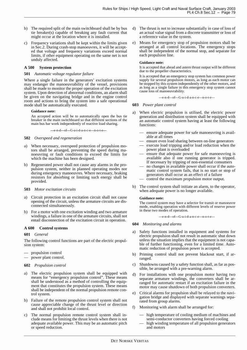
Rules for Ships / High Speed, Light Craft and Naval Surface Craft, January 2003 Pt.4 Ch.8 Sec.12 – Page 79
b) The required split of the main switchboard shall be by bustie breaker(s) capable of breaking any fault current thatmight occur at the location where it is installed.
c) Frequency variations shall be kept within the limits givenin Sec.2. During crash-stop manoeuvres, it will be accept-ed that voltage and frequency variations exceed normallimits, if other equipment operating on the same net is notunduly affected.
A 500 System protection
501 Automatic voltage regulator failure
Where a single failure in the generators’ excitation systemsmay endanger the manoeuvrability of the vessel, provisionsshall be made to monitor the proper operation of the excitationsystem. Upon detection of abnormal conditions, an alarm shallbe given on the navigating bridge and in the engine controlroom and actions to bring the system into a safe operationalmode shall be automatically executed.
Guidance note:An accepted action will be to automatically open the bus tiebreaker in the main switchboard so that different sections of themain bus bar work independently of reactive load sharing.
---e-n-d---of---G-u-i-d-a-n-c-e---n-o-t-e---
502 Overspeed and regeneration
a) When necessary, overspeed protection of propulsion mo-tors shall be arranged, preventing the speed during ma-noeuvring or fault conditions to exceed the limits forwhich the machine has been designed.
b) Regenerated power shall not cause any alarms in the pro-pulsion system, neither in planned operating modes norduring emergency manoeuvres. Where necessary, brakingresistors for absorbing or limiting such energy shall beprovided.
503 Motor excitation circuits
a) Circuit protection in an excitation circuit shall not causeopening of the circuit, unless the armature circuits are dis-connected simultaneously.
b) For a motor with one excitation winding and two armaturewindings, a failure in one of the armature circuits, shall notentail disconnection of the excitation circuit in operation.
A 600 Control systems
601 General
The following control functions are part of the electric propul-sion system:
— propulsion control— power plant control.
602 Propulsion control
a) The electric propulsion system shall be equipped withmeans for “emergency propulsion control”. These meansshall be understood as a method of controlling the equip-ment that constitutes the propulsion system. These meansshall be independent of the normal propulsion remote con-trol system.
b) Failure of the remote propulsion control system shall notcause appreciable change of the thrust level or directionand shall not prohibit local control.
c) The normal propulsion remote control system shall in-clude means for limiting the thrust levels when there is notadequate available power. This may be an automatic pitchor speed reduction.
d) The thrust is not to increase substantially in case of loss ofan actual value signal from a discrete transmitter or loss ofa reference value in the system.
e) Means for emergency stop of propulsion motors shall bearranged at all control locations. The emergency stopsshall be independent of the normal stop, and separate foreach propulsion line.
Guidance note:It is accepted that ahead and astern thrust output will be differentdue to the propeller characteristics.It is accepted that an emergency stop system has common powersupply for several propulsion motors, as long as each motor canbe stopped by this system independently of the other motors, andas long as a single failure in this emergency stop system cannotcause loss of manoeuvrability.
---e-n-d---of---G-u-i-d-a-n-c-e---n-o-t-e---
603 Power plant control
a) When electric propulsion is utilised, the electric powergeneration and distribution system shall be equipped withan automatic control system having at least the followingfunctions:
— ensure adequate power for safe manoeuvring is avail-able at all times
— ensure even load sharing between on-line generators— execute load tripping and/or load reduction when the
power plant is overloaded— ensure that adequate power for safe manoeuvring is
available also if one running generator is tripped.If necessary by tripping of non-essential consumers
— no changes in available power shall occur if the auto-matic control system fails, that is no start or stop ofgenerators shall occur as an effect of a failure
— control the maximum propulsion motor output.
b) The control system shall initiate an alarm, to the operator,when adequate power is no longer available.
Guidance note:The control system may have a selector for transit or manoeuvremode, enabling operation with different levels of reserve powerin these two modes of operation.
---e-n-d---of---G-u-i-d-a-n-c-e---n-o-t-e---
604 Monitoring and alarms
a) Safety functions installed in equipment and systems forelectric propulsion shall not result in automatic shut downunless the situation implies that the equipment is not capa-ble of further functioning, even for a limited time. Auto-matic reduction of propulsion power is accepted.
b) Priming control shall not prevent blackout start, if ar-ranged.
c) Shutdowns caused by a safety function shall, as far as pos-sible, be arranged with a pre-warning alarm.
d) For installations with one propulsion motor having twoseparate armature windings, the converters shall be ar-ranged for automatic restart if an excitation failure in themotor may cause shutdown of both propulsion converters.
e) Critical alarms for propulsion shall be relayed to the navi-gation bridge and displayed with separate warnings sepa-rated from group alarms.
f) Monitoring with alarm shall be arranged for:
— high temperature of cooling medium of machines andsemi-conductor converters having forced cooling
— high winding temperature of all propulsion generatorsand motors
DET NORSKE VERITAS

Rules for Ships / High Speed, Light Craft and Naval Surface Craft, January 2003Pt.4 Ch.8 Sec.12 – Page 80
— loss of flow of primary and secondary coolants of ma-chines and semi-conductor converters having closedcooling method with a heat exchanger, when this flowis not caused by the propulsion motor itself. Auxiliarycontacts from motor starters may be used for this pur-pose
— lubricating oil pressure for machines with forced oillubrication
— leakage of water-air heat exchanger for cooling of ma-chines and semi-conductor converters
— earth fault for main propulsion circuits— earth fault for excitation circuits. (This may be omit-
ted in circuits of brushless excitation systems and formachines rated less than 500 kW)
— fuses for filter units, or for other components wherefuse failure is not evident.
g) A request for manual load reduction shall be issued, visu-ally and acoustically on the bridge, or an automatic loadreduction shall be arranged in case of:
— low lubricating oil pressure to propulsion generatorsand motors
— high winding temperature in propulsion generatorsand motors
— failure of cooling in machines and converters.
Guidance note:High-high, or extreme high, temperatures may, when higher thanthe high alarm limit, cause shut down of the affected equipment.For redundancy requirements, see 200. Critical alarms for pro-pulsion machinery are alarms causing automatic shutdown orload reduction of parts of the propulsion power.
---e-n-d---of---G-u-i-d-a-n-c-e---n-o-t-e---
605 Instruments
a) A temperature indicator for directly reading the tempera-ture of the stator windings of generators and propulsionmotors shall be located in the control room.
b) The following values shall be displayed in the controlroom or on the applicable converter:
— stator current in each motor— field current in each motor (if applicable).
c) For each generator: A power factor meter or kVAr meter.
d) On the bridge and in the control room, instruments shall beprovided for indication of consumed power and poweravailable for propulsion.
e) At each propulsion control stand, indications, based onfeedback signals, shall be provided for pitch or direction ofrotation, speed, and azimuth, if applicable.
f) Indications as listed for control stands shall be arranged inthe engine control room, even if no control means are pro-vided.
Guidance note:When the rated power of semi-conductors is a substantial part ofthe rated power of the generators, it should be ensured that meas-urements are displayed in true root mean square values. Temper-ature indicators may be omitted for winding temperatures that aredisplayed on the alarm system display.
---e-n-d---of---G-u-i-d-a-n-c-e---n-o-t-e---
B. Torsional Vibrations
B 100 General
101 Documentation
The calculations are to contain:
— objectives— description of the method— plant or system layout— conditions— assumptions— conclusion.
The source of all essential data is to be listed. For data that can-not be given as constant parameters (e.g. see 102), the assumedparameter dependency and/or tolerance range is to be speci-fied.
The conclusion is to be based on a comparison between calcu-lated dynamic response and the permissible values for all thesensitive parts in the plant.
102 Parameter uncertainty
In all vibration calculations the variation of essential data suchas dynamic characteristics of flexible couplings, bearings, andfoundations, are to be considered. In particular, rubber cou-plings that have wide tolerances for stiffness and damping areto be considered. Normally, it is not required to perform calcu-lations with all combinations of these extreme data, but as aminimum the influence of such wide tolerances is to be quali-tatively considered and addressed in the conclusions.
For couplings having stiffness with strong dependency on vi-bratory torque and/or mean torque and/or temperature (as aconsequence of power loss) it may be required to carry out ei-ther iterative direct calculations or simulation calculationwhere these dependencies are included.
103 Symbols and definitions
Symbols and definitions are to be in compliance with Ch.3Sec.1 G101 and Ch.3 Sec.1 G102.
B 200 Vibration measurements201 Reference
Rule requirements are to be in compliance with Ch.3 Sec.1G201 and Ch.3 Sec.1 G202.
B 300 Steady state - torsional vibration301 Extent of calculations
Natural frequency calculations are to be carried out in compli-ance with Ch.3 Sec.1 G301 item a).
In the case where there is a resonant condition in the runningrange, forced response calculations in conjunction with stresscalculations are required to prove that failure of the shaftingwill not occur as a result of high cycle fatigue.
302 Calculation method
To be in compliance with Ch.3 Sec.1 G302 items a), c), d), h)and j).
If excitations caused by the electric motor are included in theforced vibration calculation the excitation models shall be doc-umented.
303 Acceptance criteria
To be in compliance with Ch.3 Sec.1 G303 items d), e), f), g)and h).
B 400 Transient torsional vibration401 General
Transient vibration caused by the electric motor are not to bedetrimental to the power transmitting elements, such as cou-plings and gears.
Transient torsional vibration can be analysed by simulation us-ing numeric integration in the time domain. The purpose of thecalculation is to determine the peak torque and torque ampli-tudes that occur before the safety system (circuit breaker) be-
DET NORSKE VERITAS

Rules for Ships / High Speed, Light Craft and Naval Surface Craft, January 2003 Pt.4 Ch.8 Sec.12 – Page 81
comes active.
The plant can be described as a lumped mass system, but es-sentially simplified as described in Ch.3 Sec.1 G302 item e).
402 Starting operations
Impact load analyses of direct start-up and star-delta switcho-ver for asynchronous motors are to be analysed, upon requestby the Society, see A302 item b).
403 Short circuit in electric motors
Impact load analyses of short circuit excitation torque is to beanalysed for propulsion units according to A302 item b).
If the short circuit excitation torque (in the air gap between ro-tor and stator) is not specified, it can be assumed as:
T = T0 [10 e-t/0.4 sin(Ω t) − 5 e-t/0.4 sin(2Ω t)]Ω/2π = net frequency (50 or 60 Hz)t = time (s).
The duration to be considered is 1 s.
404 Acceptance criteria
Transient torsional vibrations are to be in compliance withCh.3 Sec.1 G405.
C. Verification
C 100 Factory testing or manufacturer’s testing101 Survey and test upon completion
a) Upon completion, the electric propulsion system shall besubject to final tests at a sea trial.
b) The final test at sea assumes that satisfactory tests of allsubsystems have been carried out.
c) The test program is to include tests of the propulsion plantin normal and abnormal conditions.
d) Start-up and stop sequences shall be tested, also as control-led by the power management system, when relevant.
e) Safety functions, alarms and indicators shall be tested.
f) All control modes shall be tested from all control loca-tions.
g) Required level of redundancy shall be verified throughtests.
DET NORSKE VERITAS
Rules for Ships / High Speed, Light Craft and Naval Surface Craft, January 2003Pt.4 Ch.8 Sec.13 – Page 82
SECTION 13DEFINITIONS
A. Definitions
A 100 General101 Electrical installations
The term electrical installations is an all-inclusive general ex-pression that is not limited to the physical installations. Forphysical installations, the wording, "installation of…" is used.
102 Normally
The term "normally", or "normally not", when used in theserules, shall basically be understood as a clear requirement inline with "shall", or "shall not". However, upon request, otherdesigns may be accepted.
If the rules are used for a vessel classed by DNV, then the So-ciety shall be requested, in writing, to accept a deviating de-sign. A request giving the reasons for the design shall besubmitted.
A 200 Operational conditions201 Normal operational and habitable condition
Normal operational and habitable condition: A condition underwhich the vessel, as a whole, is in working order and function-ing normally. As a minimum, the following functions shall beoperational: Propulsion machinery, steering gear, safe naviga-tion, fire and flooding safety, internal and external communi-cations and signals, means of escape, emergency boat winches,anchor winches. Additionally, designed comfortable condi-tions for habitability, including; cooking, heating, domestic re-frigeration, mechanical ventilation, sanitary and fresh water.All utility systems for the listed functions shall be included.
202 Emergency condition
An emergency condition is a condition under which any serv-ices needed for normal operational and habitable conditionsare not in working order due to the failure of the main sourceof electrical power.
203 Dead ship condition
Dead ship condition is the condition under which the main pro-pulsion plant, boilers and auxiliaries are not in operation due tothe absence of power. Batteries and or pressure vessels forstarting of the main and auxiliary engines are considered de-pleted. Emergency generation is considered available. For amore detailed definition of dead ship, see Ch.1 of the Rules forClassification of Ships.
204 Blackout condition
Blackout is a sudden loss of electric power in the main distri-bution system. All means of starting by stored energy is avail-able.
A 300 Services301 Essential services
a) Essential (primary essential) services are those servicesthat need to be in continuous operation for maintaining thevessel’s manoeuvrability in regard to propulsion and steer-ing. Additional class notations may extend the term essen-tial services. Such extensions, if any, can be found in therelevant rule chapters.
b) Examples of equipment and or systems for essential serv-ices covered by main class:
— control, monitoring and safety devices or systems forequipment for essential services
— scavenging air blower, fuel oil supply pumps, fuelvalve cooling pumps, lubricating oil pumps and fresh-water cooling water pumps for main and auxiliary en-gines
— viscosity control equipment for heavy fuel oil— ventilation necessary to maintain propulsion— forced draught fans, feed water pumps, water circulat-
ing pumps, condensate pumps, oil burning installa-tions, for steam plants on steam turbine vessels, andalso for auxiliary boilers on vessels where steam isused for equipment supplying primary essential serv-ices
— steering gears— azimuth thrusters which are the sole means for propul-
sion or steering - with lubricating oil pumps, coolingwater pumps
— electrical equipment for electric propulsion plant -with lubricating oil pumps and cooling water pumps
— pumps or motors for controllable pitch propulsion orsteering propellers, including azimuth control
— hydraulic pumps supplying the above equipment— electric generators and associated power sources sup-
plying the above equipment.
302 Important services
a) Important (secondary essential) services are those servicesthat need not necessarily be in continuous operation formaintaining for the vessel’s manoeuvrability, but whichare necessary for maintaining the vessels functions as de-fined in Pt.1 Ch.1 Sec.2 of the Rules for Classification ofShips, or other relevant parts of the rules. Important elec-trical consumers are electrical consumers serving impor-tant services. Additional class notations may extend theterm important services. Such extensions, if any, can befound in the relevant rule chapters.
b) Examples of equipment or systems for important servicescovered by main class:
— anchoring system— thrusters not part of steering or propulsion— fuel oil transfer pumps and fuel oil treatment equip-
ment— lubrication oil transfer pumps and lubrication oil treat-
ment equipment— pre-heaters for heavy fuel oil— seawater pumps— starting air and control air compressors— bilge, ballast and heeling pumps— fire pumps and other fire extinguishing medium appli-
ances— ventilating fans for engine and boiler rooms— ventilating fans for gas dangerous spaces and for gas
safe spaces in the cargo area on tankers— inert gas fans— navigational lights and signals— navigation equipment— internal safety communication equipment— fire detection and alarm system— main lighting system— electrical equipment for watertight closing appliances— electric generators and associated power sources sup-
plying the above equipment— hydraulic pumps supplying the above equipment— control, monitoring and safety systems for cargo con-
tainment systems— control, monitoring and safety devices or systems for equipment to important services
DET NORSKE VERITAS

Rules for Ships / High Speed, Light Craft and Naval Surface Craft, January 2003 Pt.4 Ch.8 Sec.13 – Page 83
— jacking motors.
303 Emergency services
a) Emergency services are those services that are essentialfor safety in an emergency condition.
b) Examples of equipment and systems for emergency serv-ices:
— equipment and systems that need to be in operation inorder to maintain, at least, those services that are re-quired to be supplied from the emergency source ofelectrical power
— equipment and systems that need to be in operation inorder to maintain, at least, those services that are re-quired to be supplied from the accumulator battery forthe transitional source(s) of emergency electricalpower
— equipment and systems for starting and control ofemergency generating sets
— equipment and systems for starting and control ofprime movers (e.g. diesel engines) for emergency firefighting pumps
— equipment and systems that need to be in operation forthe purpose of starting up manually, from a "deadship" condition, the prime mover of the main source ofelectrical power (e.g. the emergency compressor)
— equipment and systems that need to be in operation forthe purpose of fire fighting in the machinery spaces.This includes emergency fire fighting pumps withtheir prime mover and systems, when required accord-ing to Pt.3 Ch.3 Sec.10 of the Rules for Classificationof Ships
— equipment and systems that are needed for the pur-pose of exhausting or removing for example CO2 fireextinguishing medium from the machinery spaces af-ter a fire, in order to allow for access to the spaces.
c) Further requirements for emergency services are given inSec.2.
304 Non-important services
Non-important services are those services not defined as es-sential or important; or those services that are not defined, ac-cording to 301, 302 and 303.
A 400 Installation
401 Short circuit proof installation
Short circuit proof installation means one of the followingthree methods:
— bare conductors mounted on isolating supports— single core cables without metallic screen or armour or
braid, or with the braid fully insulated by heat shrinksleeves in both ends
— insulated conductors (wires) from different phases keptseparated from each other and from earth by supports ofinsulating materials, or by the use of outer extra sleeves
— double insulated wires or conductors.
A 500 Area definitions
501 Open deck
Open deck is a deck that is completely exposed to the weatherfrom above or from at least one side.
A 600 Hazardous area
601 Area definitions
a) A hazardous area is an area (zones and spaces) containinga source of hazard and or in which explosive gas and air
mixture exists, or may normally be expected to be presentin quantities such as to require special precautions for theconstruction and use of electrical equipment and machin-ery. Hazardous areas are divided into zone 0, 1, and 2 inaccordance with an area classification.
b) If electrical installations are based on an areas' classifica-tion, this classification shall be based on a relevant IECstandard.
602 Certified safe equipment
Certified safe equipment is equipment certified by an inde-pendent national test institution or competent body to be in ac-cordance with a recognised standard for electrical apparatus inhazardous areas.
603 Marking of certified safe equipment
Certified safe equipment shall be marked in accordance with arecognised standard for electrical apparatus in hazardous are-as. This includes at least:
— Ex-protection type and Ex certificate number— temperature class, according to Table A1— gas and equipment group, according to Table A2.
Guidance note:According to the "ATEX"-directive that will enter into force inEurope by 2002, all electrical equipment suitable for installationin a hazardous area shall be marked in accordance with the re-quirements given in this directive. The new marking shall be inaddition to Ex-marking related to the various protection methods(enabling easy identification for in which zone it can be in-stalled).
ATEX directive divides equipment into 3 safety categories,marked on equipment:
— Category 1 equipment is allowed, if certified safe, into zone0.
— Category 2 equipment is allowed, if certified safe, into zone1.
— Category 3 equipment is suitable for zone 2 only.
The letter G indicates the equipment suitability for gas atmos-pheres.
The letter D indicates the equipment suitability for dust atmos-pheres.
Table A1 Equipment and gas groups
Gas groups (IEC sur-face industry
= II)Representative gas
NEC 500(US surface
industry= class 1)
II A Propane Group DII B Ethylene Group CII C Hydrogen Group BII C Acetylene Group A
Table A2 Temperature classes Temperature classes
(equipment maximum temperature)
IEC and EN norms
Ignition temperature of gas or vapour
(°C)
Corresponding NEC (US) tem-perature classes
T1 Above 450 T 1T2 Above 300 T 2 *T3 Above 200 T 3 *T4 Above 135 T 4 *T5 Above 100 T 5T6 Above 85 T 6
* Intermediate values of temperature classes by letter marking ABCD ex-ist.
DET NORSKE VERITAS

Rules for Ships / High Speed, Light Craft and Naval Surface Craft, January 2003Pt.4 Ch.8 Sec.13 – Page 84
Marking of protection methods, gas grouping, temperature class,etc., corresponds to the IEC 60079 standard system (or equiva-lent to the CENELEC 50014-39 standard series) as given in 603.
---e-n-d---of---G-u-i-d-a-n-c-e---n-o-t-e---
604 TE-time
The TE –time is the time it takes for the motor, starting fromnormal operating temperature, to reach the temperature givenby the temperature class of the Ex certification if the rotor islocked. The TE-time is stated in the Ex-certificate for the mo-tor.
605 Simple apparatus
a) A simple (non-energy storing) apparatus is an electricalcomponent of simple construction with no, or low energyconsumption or storage capacity, and which is not capableof igniting an explosive atmosphere. Normal maximalelectrical parameters are 1.5 V, 100 mA and 25 mW. Thecomponent shall not contain inductance or capacitance.Components such as thermocouples or passive switchesare typical examples of simple, non-energy storing, appa-ratus.
b) Simple (non-energy storing) apparatus, when used in anintrinsically safe circuit, generally does not need to be cer-tified safe, provided that such apparatus is constructed inaccordance with IEC 60079-14, Part 14: "Electrical appa-ratus for explosive gas atmospheres".
A 700 Sources of power, generating station and distribu-tion
701 Main source of electrical power
A main source of electrical power is a source intended to sup-ply electrical power to the main switchboard(s) for distributionto all services necessary for maintaining the vessel in normaloperational and habitable conditions.
Guidance note:Main source of electrical power may be generators and/or batter-ies.
A generator prime mover and associated equipment is called"generators' primary source of power".
---e-n-d---of---G-u-i-d-a-n-c-e---n-o-t-e---
702 Emergency source of electrical power
An emergency source of electrical power is a source intendedto supply the emergency switchboard and/or equipment foremergency services in the event of failure of the supply fromthe main source of electrical power.
Guidance note:Emergency source of electrical power may be generator(s) orbattery(ies).
A generator prime mover and associated equipment is called"emergency generators' primary source of power".
---e-n-d---of---G-u-i-d-a-n-c-e---n-o-t-e---
703 Main electric power supply system
a) A main electric power supply system consists of the mainsource of electric power and associated electrical distribu-tion. This includes the main electrical generators, batter-ies, associated transforming equipment if any, the mainswitchboards (MSB), distribution boards (DB) and all ca-bles from generators to the final consumer.
b) Control systems and auxiliary systems needed to be in op-eration for the above mentioned systems or equipment areincluded in this term.
704 Emergency electric power supply system
a) An emergency electric power supply system consists ofthe emergency source of electric power and associatedelectrical distribution. This includes emergency genera-tors, batteries, associated transforming equipment if any,the transitional source of emergency power, the emergen-cy switchboards (ESB), emergency distribution boards(EDB) and all cables from the emergency generator to thefinal consumer.
b) A transitional source of power is considered to be part ofthe emergency electric power supply system.
c) Control systems and auxiliary systems needed to be in op-eration for the above mentioned systems or equipment areincluded in this term.
705 Main generating station
A main generating station is a space in which the main sourceof electrical power is situated.
706 System with high resistance earthed neutral
A system with high resistance earthed neutral is a systemwhere the neutral is earthed through a resistance with numeri-cal value equal to, or somewhat less than, 1/3 of the capacitivereactance between one phase and earth.
707 System with low resistance earthed neutral
A system with low resistance earthed neutral is a system wherethe neutral is earthed through a resistance which limits theearth fault current to a value of minimum 20% and maximum100% of the rated full load current of the largest generator.
708 Conductor, core, wire, cable
a) A conductor is a part of a construction or circuit designedfor transmission of electric current.
b) A core is an assembly consisting of a conductor and itsown insulation.
c) A wire is an assembly consisting of one core where the in-sulation is at least flame retardant.
d) In electrical terms, a cable is an assembly consisting of:
— one or more cores— assembly protection— individual covering(s) (if any)— common braiding (if any)— protective covering(s) (if any)— inner and/or outer sheath.
Additional uninsulated conductors may be included in thecable.
e) A cable may be either Class 2 or Class 5 as defined in IEC60228. In a Class 2 cable the conductor is made up by aminimum number of strands. In a Class 5 cable the con-ductor is made up by many small strands with a maximumsize according to IEC 60288.
709 Neutral conductor
A neutral conductor is a conductor connected to the neutralpoint of a system, and capable of contributing to the transmis-sion of electric energy.
A 800 Switchboard definitions801 Main switchboard (MSB)
a) A main switchboard is a switchboard directly supplied bythe main source of electrical power or power transformerand intended to distribute electrical energy to the vessel’sservices.
b) Switchboards not being directly supplied by the mainsource of power will be considered as main switchboardswhen this is found relevant from a system and operationalpoint of view.
DET NORSKE VERITAS

Rules for Ships / High Speed, Light Craft and Naval Surface Craft, January 2003 Pt.4 Ch.8 Sec.13 – Page 85
Guidance note:Normally, all switchboards between the main source of electricalpower and (inclusive) the first level of switchboards for powerdistribution, to small power consumers, will be considered to bemain switchboards (MSBs) (i.e. at least first level of switch-boards for each voltage level used).Cubicles for other system voltages attached to a main switch-board are considered part of the main switchboard.
---e-n-d---of---G-u-i-d-a-n-c-e---n-o-t-e---
802 Emergency switchboard (ESB)
a) An emergency switchboard is a switchboard, which in theevent of failure of the main electrical power supply sys-tem, is directly supplied by the emergency source of elec-trical power and/or the transitional source of emergencypower and is intended to distribute electrical energy to theemergency power consumers.
b) Switchboards not being directly supplied by the emergen-cy source of power may be considered as emergencyswitchboards when this is found relevant from a systemand operational point of view.
Guidance note:Normally all switchboards between the emergency source ofelectrical power and (inclusive) the first level of switchboards,for power distribution to small power consumers, will be consid-ered to be emergency switchboards (ESBs) (i.e. at least one levelof switchboards for each voltage level used).
---e-n-d---of---G-u-i-d-a-n-c-e---n-o-t-e---
803 Distribution board (DB) and emergency distributionboard (EDB)
A distribution board or an emergency distribution board is anyswitchboard utilised for distribution to electrical consumers,but which is not considered as a main or emergency switch-board.
A 900 Components and related expressions901 Definitions of words used in relation to electrical com-ponents and equipment
a) For definitions of terms related to switchgear and con-trolgear, see IEC 60947-1 for low voltage, and IEC 60470and IEC 60056 for high voltage equipment.
b) For assemblies, the following definitions are used in therules:
— Controlgear: A general term for devices used for con-trolling consumer equipment, e.g. by switching on andoff, starting and stopping a motor, controlling a mo-tor’s speed.
— Electrical components: electrical units for use in elec-trical equipment. A component is ready made by acomponent manufacturer, for use by an equipmentmanufacturer. The term component is also used forsmaller free-standing equipment like connection box-es, sensors, switches etc.
— Electrical equipment: A common term for electricalmachines, transformers, switchboards, panels, assem-blies, control units and other units made by compo-nents.
— Semi-conductor assembly: Electrical equipment thatuses semi-conductors as the main active elements, forswitching or conducting the main flow of power.
— Switchgear: A common term for devices used formaking and breaking circuits, including auxiliarycomponents such as for example short circuit andovercurrent relays, coils, etc.
c) Proof tracking index is the numerical value of the proofvoltage, in volts, at which a material withstands 50 dropswithout tracking, in accordance with IEC 60112 (i.e. avoltage value describing the isolating materials surfaceproperty to withstand tracking when wet.) Determinationof the tracking index shall be done in accordance with therequirements in IEC 60112, and is normally done by typetesting of the material by the manufacturer, before the ma-terial is available in the market.
902 Ingress protection of enclosures
Ingress protection of enclosures in regard to intrusion of parti-cles and water, normally called IP rating, is defined as follows:
Table A3 Ingress protection of enclosuresFirst charac-teristic numeral
Protection against intrusion of particles and against ac-cidental touching of live parts
0 Non-protected1 Protected against solid objects greater than 50 mm2 Protected against solid objects greater than 12.5 mm3 Protected against solid objects greater than 2.5 mm4 Protected against solid objects greater than 1.0 mm5 Dust protected6 Dust tight
Second charac-teristic numeral
Protection against intrusion of water
0 Non-protected1 Protected against dripping water2 Protected against dripping water when tilted up to 15º3 Protected against spraying water from above up to 60º
from vertical4 Protected against splashing water5 Protected against water jets6 Protected against heavy seas7 Protected against the effects of immersion8 Protected against submersion (water depth to be given)
DET NORSKE VERITAS


![DNVGL-RU-HSLC Pt.3 Ch.1 Design principles, design loads · 2020. 10. 28. · Design load area Sec.3 [3.3.1] Clarification. Distribution of crest landing moment Sec.4 [1.2.3] Sec.4](https://img.pdfslide.net/doc/110x75/612d5e011ecc515869422523/dnvgl-ru-hslc-pt3-ch1-design-principles-design-loads-2020-10-28-design-load.jpg)