Embed Size (px)
Citation preview
RDG603A10 Issue 1 Shire14 70 & 14 90 Owners Manual
SHIRE CANAL BOAT MANUAL
SHIRE 14 70
&
SHIRE 14 90
Please read in conjunction with
either Yanmar or John Deere Operational Manual
& the PRM Gearbox Manual
optional: VDO Travel Power Manual
Enter your engine identification details in the spaces provided above.
E.P. BARRUS LIMITED, Launton Road, Bicester, Oxfordshire. OX26 4UR
Tel: 01869-363636 Fax: 01869-363610 www.barrus.co.uk
RDG603A10 Issue 1 Shire14 70 & 14 90 Owners Manual Page 2 of 46
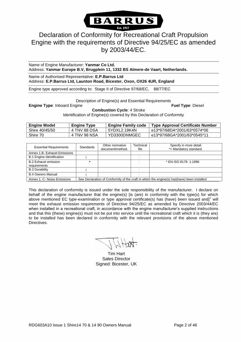
Declaration of Conformity for Recreational Craft Propulsion
Engine with the requirements of Directive 94/25/EC as amended by 2003/44/EC.
Name of Engine Manufacturer: Yanmar Co Ltd. Address: Yanmar Europe B.V, Brugplein 11, 1332 BS Almere-de Vaart, Netherlands.
Name of Authorised Representative: E.P.Barrus Ltd Address: E.P.Barrus Ltd, Launton Road, Bicester, Oxon, OX26 4UR, England
Engine type approved according to: Stage II of Directive 97/68/EC, 88/77/EC
Description of Engine(s) and Essential Requirements
Engine Type: Inboard Engine Fuel Type: Diesel Combustion Cycle: 4 Stroke
Identification of Engine(s) covered by this Declaration of Conformity
Engine Model Engine Type Engine Family code Type Approval Certificate Number
Shire 40/45/50 4 TNV 88 DSA 5YDXL2.19K4N e13*97/68DA*2001/63*0574*06
Shire 70 4 TNV 98 NSA YD3300DNMGEC e13*97/68GA*2001/63*0545*11
Essential Requirements Standards Other normative
document/method. Technical
file Specify in more detail
*= Mandatory standard.
Annex 1.B- Exhaust Emissions
B.1 Engine Identification
B.2 Exhaust emission requirements
* * EN ISO 8178- 1:1996
B.3 Durability
B.4 Owners Manual
Annex 1. C- Noise Emissions See Declaration of Conformity of the craft in which the engine(s) has(have) been installed
This declaration of conformity is issued under the sole responsibility of the manufacturer. I declare on behalf of the engine manufacturer that the engine(s) [is (are) in conformity with the type(s) for which above mentioned EC type-examination or type approval certificate(s) has (have) been issued and]
1 will
meet the exhaust emission requirements of Directive 94/25/EC as amended by Directive 2003/44/EC when installed in a recreational craft, in accordance with the engine manufacturer’s supplied instructions and that this (these) engine(s) must not be put into service until the recreational craft which it is (they are) to be installed has been declared in conformity with the relevant provisions of the above mentioned Directives.
Tim Hart Sales Director Signed: Bicester, UK
RDG603A10 Issue 1 Shire14 70 & 14 90 Owners Manual Page 3 of 46
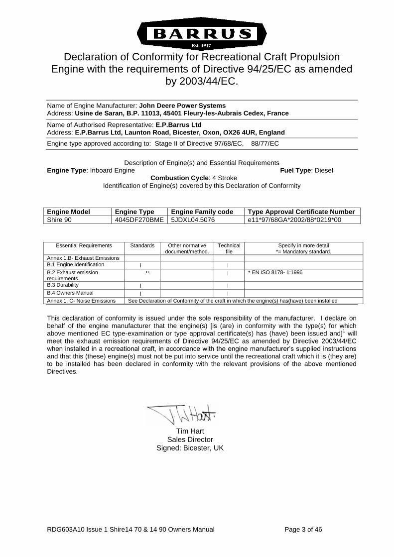
Declaration of Conformity for Recreational Craft Propulsion
Engine with the requirements of Directive 94/25/EC as amended by 2003/44/EC.
Name of Engine Manufacturer: John Deere Power Systems Address: Usine de Saran, B.P. 11013, 45401 Fleury-les-Aubrais Cedex, France
Name of Authorised Representative: E.P.Barrus Ltd Address: E.P.Barrus Ltd, Launton Road, Bicester, Oxon, OX26 4UR, England
Engine type approved according to: Stage II of Directive 97/68/EC, 88/77/EC
Description of Engine(s) and Essential Requirements
Engine Type: Inboard Engine Fuel Type: Diesel Combustion Cycle: 4 Stroke
Identification of Engine(s) covered by this Declaration of Conformity
Engine Model Engine Type Engine Family code Type Approval Certificate Number
Shire 90 4045DF270BME 5JDXL04.5076 e11*97/68GA*2002/88*0219*00
Essential Requirements Standards Other normative
document/method. Technical
file Specify in more detail
*= Mandatory standard.
Annex 1.B- Exhaust Emissions
B.1 Engine Identification
B.2 Exhaust emission requirements
* EN ISO 8178- 1:1996
B.3 Durability
B.4 Owners Manual
Annex 1. C- Noise Emissions See Declaration of Conformity of the craft in which the engine(s) has(have) been installed
This declaration of conformity is issued under the sole responsibility of the manufacturer. I declare on behalf of the engine manufacturer that the engine(s) [is (are) in conformity with the type(s) for which above mentioned EC type-examination or type approval certificate(s) has (have) been issued and]
1 will
meet the exhaust emission requirements of Directive 94/25/EC as amended by Directive 2003/44/EC when installed in a recreational craft, in accordance with the engine manufacturer’s supplied instructions and that this (these) engine(s) must not be put into service until the recreational craft which it is (they are) to be installed has been declared in conformity with the relevant provisions of the above mentioned Directives.
Tim Hart Sales Director Signed: Bicester, UK
RDG603A10 Issue 1 Shire14 70 & 14 90 Owners Manual Page 4 of 46
PLEASE NOTE:
This manual has been compiled to help you to operate your engine and its associated
parts with safety and pleasure. Please read it carefully and familiarise yourself with the
engine and its parts before operation.
E.P.Barrus reserve the right to change the specification of its products and manuals
without prior notice.
Depending upon the equipment specification of the engine and accessories fitted, there
may be discrepancies with the information presented in this handbook. No claims may
be pursued in this respect.
WARNING: THIS MANUAL FORMS AN INTEGRAL PART OF THE ENGINE IT ACCOMPANIES, IF A TRANSFER OF TITLE OCCURS, IT MUST ALWAYS BE HANDED OVER TO THE
NEW OWNER.
WARRANTY
This Limited Warranty provides coverage for five (5) years (or 2000 hours which ever
occurs first) for recreational users and three (3) years (or 2000 hours which ever occurs
first) for commercial users from the date of warranty registration. The repair or
replacement of parts, or the performance of service under this warranty, does not
extend the life of this warranty beyond its original expiry date.
PRM 260 gearboxes are covered by a three (3) year warranty for recreational users and
two (2) years for commercial users.
To ensure that you have been registered for your warranty, please ask your Boat-
Builder or Engine supplier to provide your portion of the registration form.
Engine alternator, starter motor and electrical components are only covered by a one
(1) year warranty.
RDG603A10 Issue 1 Shire14 70 & 14 90 Owners Manual Page 5 of 46
CONDITIONS THAT MUST BE MET IN ORDER TO OBTAIN WARRANTY
COVERAGE
Warranty coverage is only available from an authorised dealer in the country in which
the sale occurred. Routine maintenance outlined in the Owners Manual must be
performed using genuine parts in order to maintain warranty coverage. If the customer
performs maintenance, Barrus reserves the right to make future warranty coverage
possible only with proof of proper maintenance.
WARRANTY CLAIMS
Warranty claims shall be made by an authorised dealer or boat builder.
The dealer or boat builder will then arrange for the inspection and any necessary
repairs. If the repairs carried out are not covered by the warranty, purchaser shall pay
for all related labour and material, and any other expenses associated with that service.
WHAT IS NOT COVERED
This limited warranty does not cover routine maintenance items, adjustments, normal
wear and tear, damage caused by abnormal use, operation of the product in a manner
inconsistent with the recommended operation/duty cycle section of the Owners Manual,
accident, submersion, improper installation (proper installation specification and
techniques are set forth in the Operations and First time running sections in this
manual), use of an accessory or part not manufactured or sold by us, or alteration or
removal of parts. Expenses related to crane-out, launch, towing, storage, telephone,
rental, inconvenience, slip fees, insurance coverage, loan payments, loss of time, loss
of income, or any other types of accidental or consequential damages are not covered
by this warranty.
Failure to use John Deere approved oils and coolants will invalidate any warranty (Shire
90).
Engine electrical systems fitted with alternator boost charge systems or any other
electrical management systems other than those approved by Barrus are not covered
by warranty.
Engine and fuel equipment is not covered by warranty if bio-diesel is used in the fuel
system. Also if no type of water trap is incorporated into fuel system.
RDG603A10 Issue 1 Shire14 70 & 14 90 Owners Manual Page 6 of 46
Contents
SECTION 1 - SAFETY PRECAUTIONS ......................................................................... 8
1. General ....................................................................................................................................... 8
2. Lifting .......................................................................................................................................... 8
3. Rotating Shafts and Belts ........................................................................................................... 8
4. Exhaust System.......................................................................................................................... 8
5. Launching and Lifting Boats ....................................................................................................... 8
6. Batteries ..................................................................................................................................... 9
SECTION 2 - ENGINE IDENTIFICATION ..................................................................... 10
SECTION 3 - INSTALLATION ...................................................................................... 11
1. Ventilation ................................................................................................................................. 11
2. Engine Beds ............................................................................................................................. 11
3. Cooling System ........................................................................................................................ 11
4. Skin Tanks ................................................................................................................................ 11
5. Engine Cooling Water Inlet and Outlet Hose ........................................................................... 12
6. Pressurised Water Header Tank .............................................................................................. 12
7. Shaft Connection ...................................................................................................................... 14
8. Engine Anti-Vibration Mounts ................................................................................................... 14
9. Engine Mount Installation ......................................................................................................... 15
10. Engine Alignment ..................................................................................................................... 17
11. Electrics .................................................................................................................................... 17
12. Electrical Options...................................................................................................................... 18
13. Engine Oil ................................................................................................................................. 18
14. Fuel ........................................................................................................................................... 18
15. Coolant ..................................................................................................................................... 19
16. Calorifier ................................................................................................................................... 19
17. Control Cables .......................................................................................................................... 21
18. Domestic Battery Bank ............................................................................................................. 21
19. Control Panel ............................................................................................................................ 21
20. Exhaust System........................................................................................................................ 23
21. Hydraulic Drive Transmissions ................................................................................................. 23
22. Hydraulic Pump Drive (Shire 70) .............................................................................................. 24
23. Installation Check list ................................................................................................................ 25
SECTION 4 - OPERATION ........................................................................................... 26
1. Starting The Engine For The First Time ................................................................................... 26
RDG603A10 Issue 1 Shire14 70 & 14 90 Owners Manual Page 7 of 46
2. Starting Procedure ................................................................................................................... 26
3. Stopping Procedure .................................................................................................................. 26
4. Full Load Running .................................................................................................................... 27
5. Refuelling .................................................................................................................................. 27
6. Diesel Fuel Additive .................................................................................................................. 27
7. Twin Thermostats ..................................................................................................................... 27
8. Exhaust Back Pressure ............................................................................................................ 29
SECTION 5 - SERVICE PROCEDURE ......................................................................... 29
1. Engine Oil and Filter Change ................................................................................................... 29
2. Air Filter Check & Change ........................................................................................................ 30
3. Gearbox Oil Change ................................................................................................................. 30
4. Disposal of Oil and Related Items ............................................................................................ 31
5. Primary Fuel Filter Water Drain ................................................................................................ 31
6. Primary Fuel Filter Change ...................................................................................................... 32
7. Secondary Fuel Filter Change .................................................................................................. 32
8. Fuel System Bleeding .............................................................................................................. 32
9. Cooling System ........................................................................................................................ 33
10. Belt Adjustment ........................................................................................................................ 34
11. Belt Maintenance ...................................................................................................................... 34
12. Belt Replacement ..................................................................................................................... 34
13. Deluxe Panel Maintenance ...................................................................................................... 36
SECTION 6 - SERVICE PARTS .................................................................................... 37
SECTION 7 - SERVICE SCHEDULE ............................................................................ 37
SECTION 8 - WIRING DIAGRAMS ............................................................................... 39
1. Engine Wiring Diagram, Shire 70 ............................................................................................. 39
2. Engine Wiring Diagram, Shire 90 (12 Volt) .............................................................................. 40
3. Deluxe Panel Wiring Diagram (12 Volt) ................................................................................... 41
4. RDG20710111 - Deluxe Instrument Panel ............................................................................... 42
5. VDO 8kW Wiring Diagram and overall dimensions .................................................................. 43
6. VDO 5kW Travel Power System .............................................................................................. 44
SECTION 9 - DEALER LIST ......................................................................................... 45
SHIRE RECORD CARD ................................................................................................ 46
RDG603A10 Issue 1 Shire14 70 & 14 90 Owners Manual Page 8 of 46
SECTION 1 - Safety Precautions
1. General
It is the responsibility of the installer/operator to ensure that the finished installation
complies with the relevant health & safety requirements and the recreational craft
directive before commissioning.
Ensure that the engine battery isolator switch is in the off position and the key removed
from the control panel before carrying out any maintenance or repairs.
2. Lifting
The lifting points supplied with the engine are for lifting the engine/gearbox only. A
suitable spreader bar must be employed to prevent over-stressing either bracket during
any lift.
3. Rotating Shafts and Belts
The engine and its accessories are not intended to be put into operation until it is
integrated into the boat as a whole. No person should be in the engine compartment
whilst the engine is running.
4. Exhaust System
Exhaust gases may have temperatures as high as 650oc and contain elements which
are harmful if ingested. It is therefore essential that exhaust systems are gas tight and
lagged to prevent accidental burning.
5. Launching and Lifting Boats
Care must be taken when launching or craning new boats into or out of the waterway,
so that water does not enter the engine via the exhaust system or air vents. It is
recommended that these are blocked temporarily whilst undertaking this procedure.
RDG603A10 Issue 1 Shire14 70 & 14 90 Owners Manual Page 9 of 46
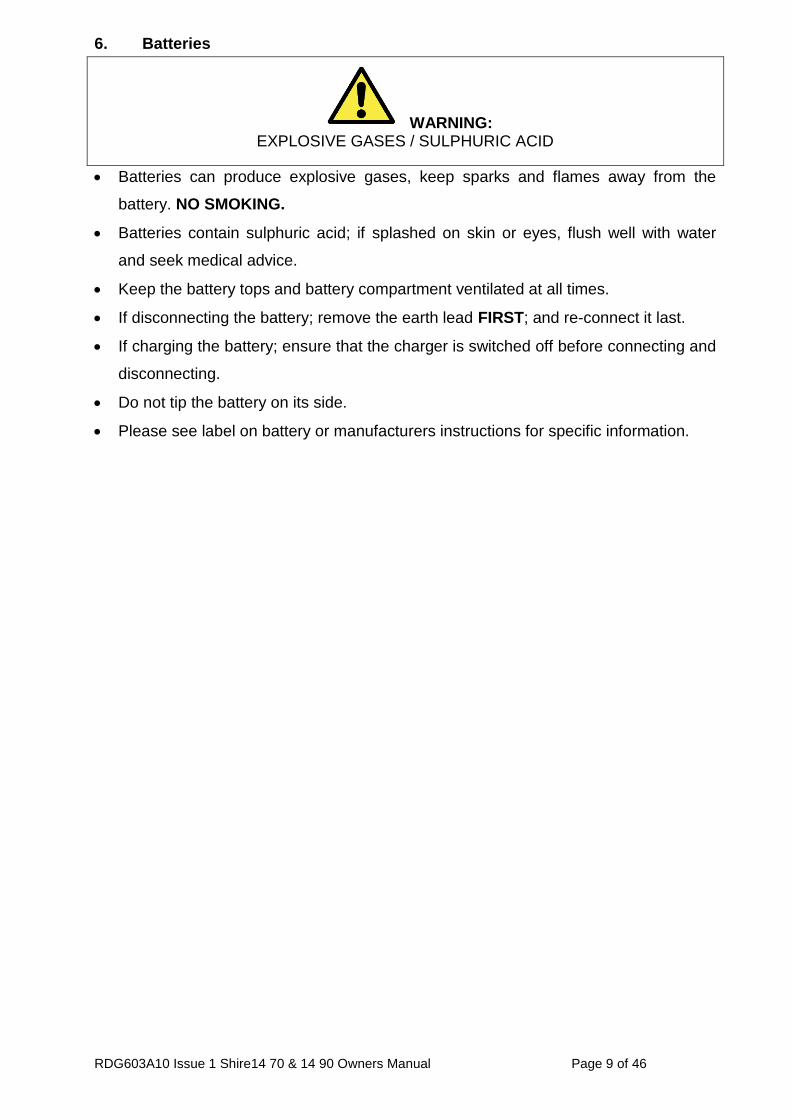
6. Batteries
WARNING: EXPLOSIVE GASES / SULPHURIC ACID
Batteries can produce explosive gases, keep sparks and flames away from the
battery. NO SMOKING.
Batteries contain sulphuric acid; if splashed on skin or eyes, flush well with water
and seek medical advice.
Keep the battery tops and battery compartment ventilated at all times.
If disconnecting the battery; remove the earth lead FIRST; and re-connect it last.
If charging the battery; ensure that the charger is switched off before connecting and
disconnecting.
Do not tip the battery on its side.
Please see label on battery or manufacturers instructions for specific information.
RDG603A10 Issue 1 Shire14 70 & 14 90 Owners Manual Page 10 of 46
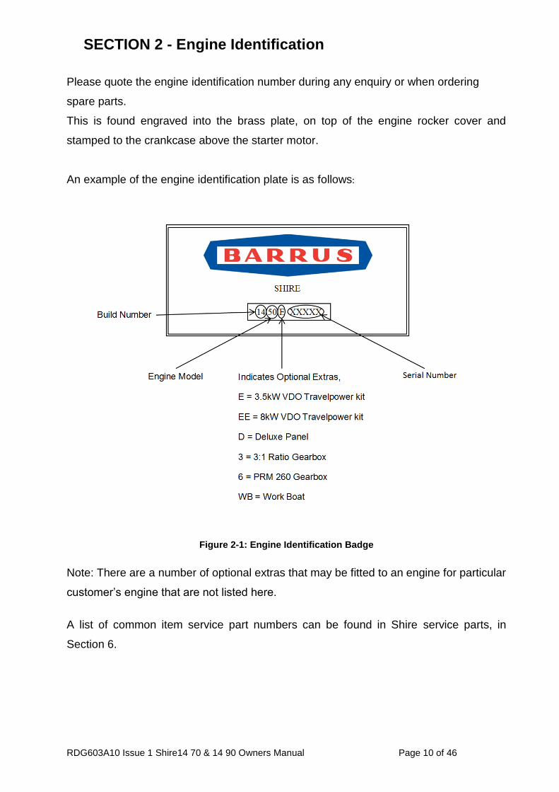
SECTION 2 - Engine Identification
Please quote the engine identification number during any enquiry or when ordering
spare parts.
This is found engraved into the brass plate, on top of the engine rocker cover and
stamped to the crankcase above the starter motor.
An example of the engine identification plate is as follows:
Figure 2-1: Engine Identification Badge
Note: There are a number of optional extras that may be fitted to an engine for particular
customer’s engine that are not listed here.
A list of common item service part numbers can be found in Shire service parts, in
Section 6.
RDG603A10 Issue 1 Shire14 70 & 14 90 Owners Manual Page 11 of 46
SECTION 3 - Installation
1. Ventilation
All internal combustion engines radiate heat and require cool, clean air for complete
combustion purposes.
Please ensure that adequate engine room ventilation is provided, by fitting at least
two vents of an aperture of not less than 15,000 mm2 each, (24 in2).
An allowance must be made for any grills or louvres placed in the airflows and
generally, an increase of 25% in area is sufficient to overcome any restriction
problems.
2. Engine Beds
These should be a minimum of 10mm thick and extended rearward and be welded
to the hull and forward to the bulkhead. There must be webs or gussets welded in
place to prevent flexing.
3. Cooling System
Ensure pipe work to and from the skin tanks is of sufficient bore. A minimum of
45mm (1 ¾”) for Shire 90 and 38-40mm (1 ½”) is recommended. Ensure tight bends
and elbows are avoided or kept to a minimum.
For Shire 90; if twin skin cooling tanks or additional floor tanks are used which add
greatly to restriction to flow. The water pump drive pulley can be changed for a
smaller diameter one to increase pump speed and flow rate. John Deere part no.:
R115250
4. Skin Tanks
The ideal skin tank internal thickness should be not less than 50mm and not exceed
75mm; the table below will indicate a suitable size however volume will not
compensate for lack of surface area. It should be recognised that fitting a large
calorifier would increase the theoretical cooling capacity only until it is up to
temperature. It is unlikely that a boat on the inland waterways will operate at full
power for more than short periods. The engine cooling water outlets are on the right
hand (starboard) side of the engine, for Shire 70 and inlet on left hand side (port)
and outlet on right hand side (starboard) on the Shire 90.
RDG603A10 Issue 1 Shire14 70 & 14 90 Owners Manual Page 12 of 46
Hei
gh
t
Length
Air Bleed Points
Coolant to
Engine
Coolant from
Engine
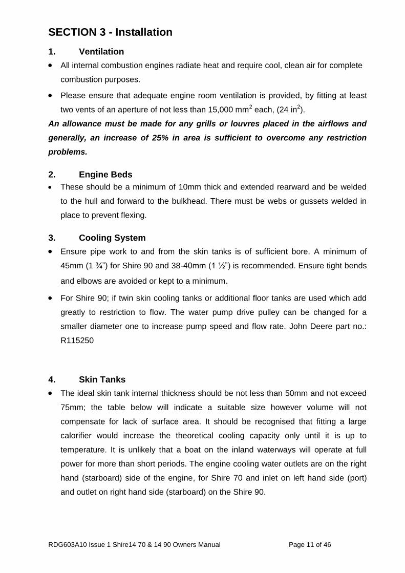
Figure 3-1: Skin Tank Flow Diagram
Recommended Skin Tank Size
Engine HP KW Skin tank Surface
area m2 Suggested Height mm
Suggested Length mm
90 90 67 2.15 952 2258
70 70 51.7 1.55 840 1850
Note: Skin tank size must be increased by approx. 10% if a hydraulic drive transmission
is fitted.
5. Engine Cooling Water Inlet and Outlet Hose
Use a good quality hose that cannot collapse or kink and is capable of working at
temperatures in excess of 100⁰C.
6. Pressurised Water Header Tank
The pressurised water bottle should be mounted higher than the level of the engine
and no more than 1 metre from the engine. This will prevent cooling system air
locks.
The header tank has two hose connections of different internal diameters.
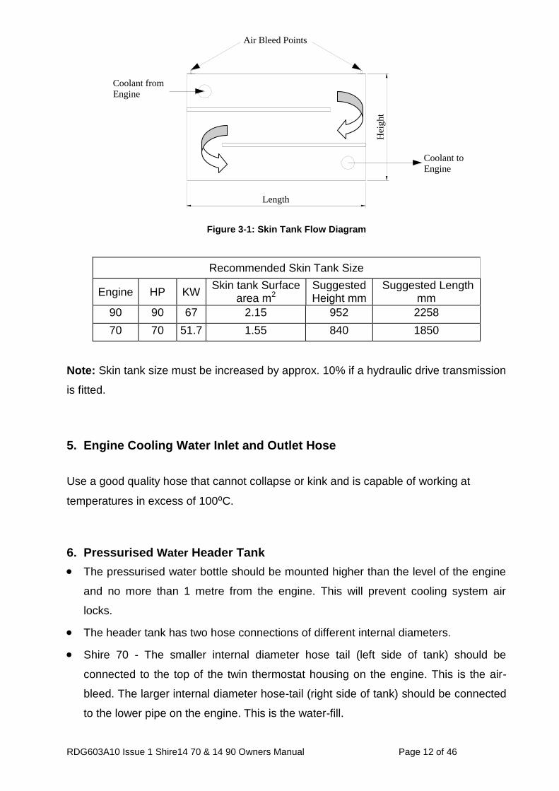
Shire 70 - The smaller internal diameter hose tail (left side of tank) should be
connected to the top of the twin thermostat housing on the engine. This is the air-
bleed. The larger internal diameter hose-tail (right side of tank) should be connected
to the lower pipe on the engine. This is the water-fill.
RDG603A10 Issue 1 Shire14 70 & 14 90 Owners Manual Page 13 of 46
Note: A constant rise on pipework is required to prevent air locks.
Figure 3-2: Shire 70 Header Tank Connections
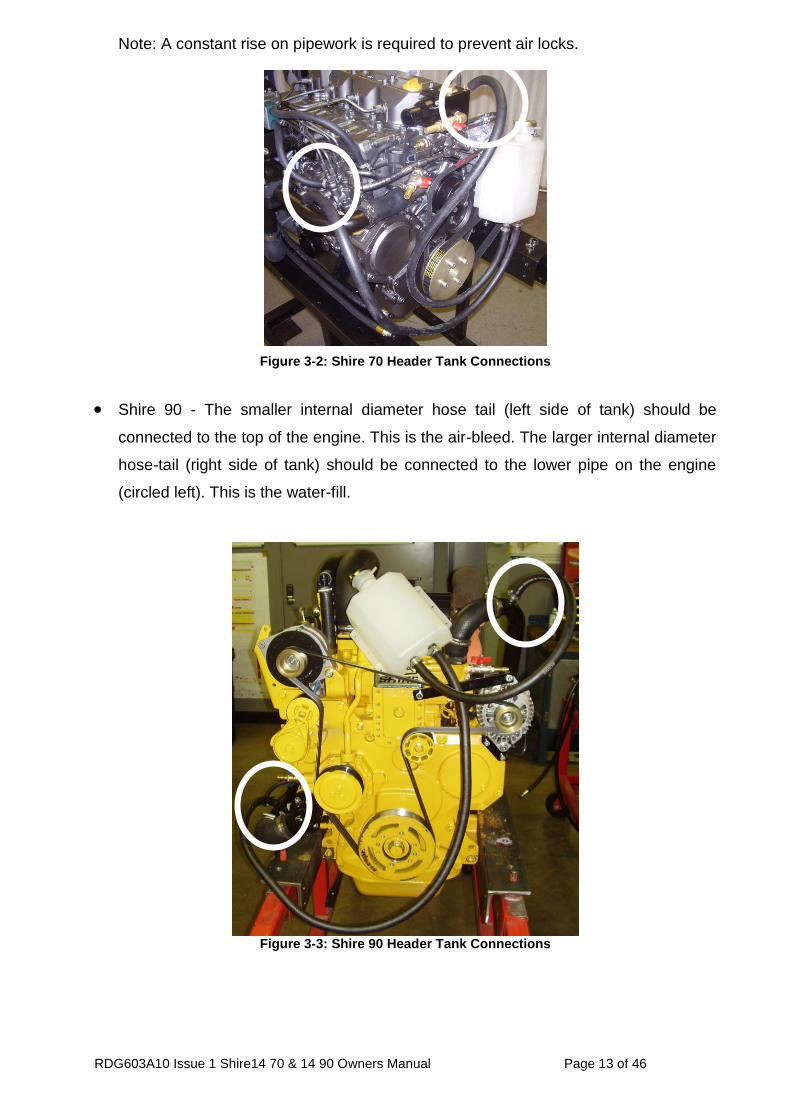
Shire 90 - The smaller internal diameter hose tail (left side of tank) should be
connected to the top of the engine. This is the air-bleed. The larger internal diameter
hose-tail (right side of tank) should be connected to the lower pipe on the engine
(circled left). This is the water-fill.
Figure 3-3: Shire 90 Header Tank Connections
RDG603A10 Issue 1 Shire14 70 & 14 90 Owners Manual Page 14 of 46
7. Shaft Connection
Some type of flexible coupling must be used to connect the gearbox output flange to
the propeller shaft flange.
8. Engine Anti-Vibration Mounts
Ensure that the engine feet do not end up at the top of the thread on the engine
mounts, this puts undue pressure on them and can result in excessive engine
movement and premature mount failure. Mount the engine using the steel packing
plates supplied under the engine mounts RDG3906.
Ensure that the engine has been installed for at least 24 hours before shaft
alignment is checked, this allows the mounts time to settle under the engine weight.
Ensure that the anti-vibration mount centre screw is sufficiently raised so as not to
touch the engine bed. If this occurs excessive engine vibration will be experienced
through the hull.
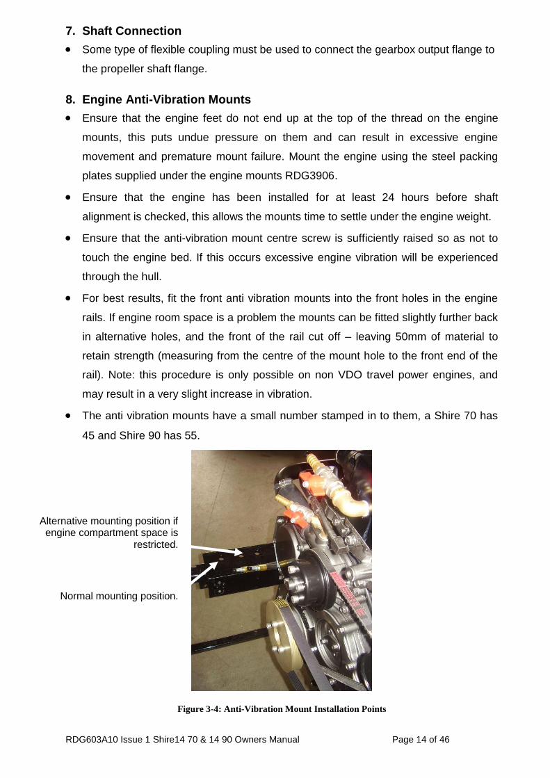
For best results, fit the front anti vibration mounts into the front holes in the engine
rails. If engine room space is a problem the mounts can be fitted slightly further back
in alternative holes, and the front of the rail cut off – leaving 50mm of material to
retain strength (measuring from the centre of the mount hole to the front end of the
rail). Note: this procedure is only possible on non VDO travel power engines, and
may result in a very slight increase in vibration.
The anti vibration mounts have a small number stamped in to them, a Shire 70 has
45 and Shire 90 has 55.
Figure 3-4: Anti-Vibration Mount Installation Points
Normal mounting position.
Alternative mounting position if engine compartment space is
restricted.
RDG603A10 Issue 1 Shire14 70 & 14 90 Owners Manual Page 15 of 46
9. Engine Mount Installation
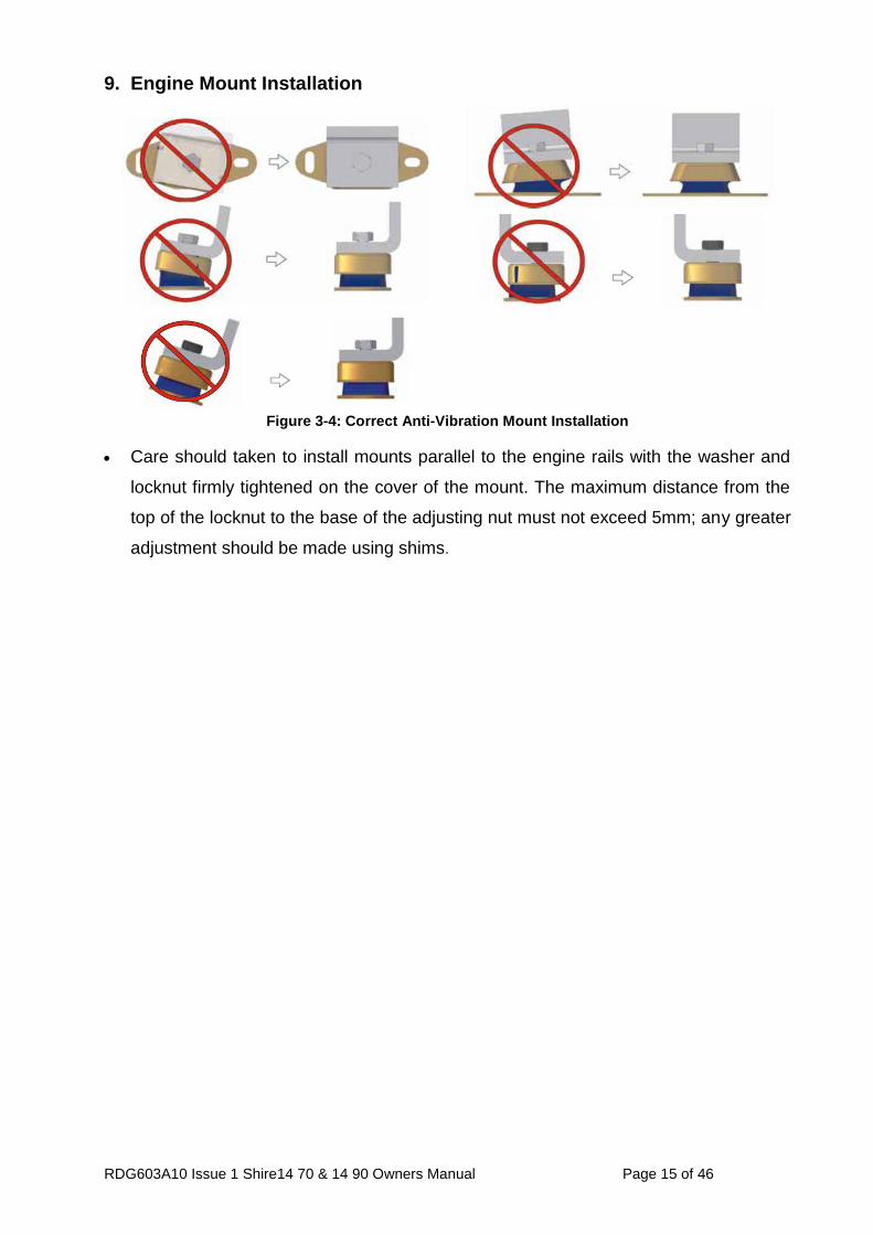
Figure 3-4: Correct Anti-Vibration Mount Installation
Care should taken to install mounts parallel to the engine rails with the washer and
locknut firmly tightened on the cover of the mount. The maximum distance from the
top of the locknut to the base of the adjusting nut must not exceed 5mm; any greater
adjustment should be made using shims.
RDG603A10 Issue 1 Shire14 70 & 14 90 Owners Manual Page 16 of 46
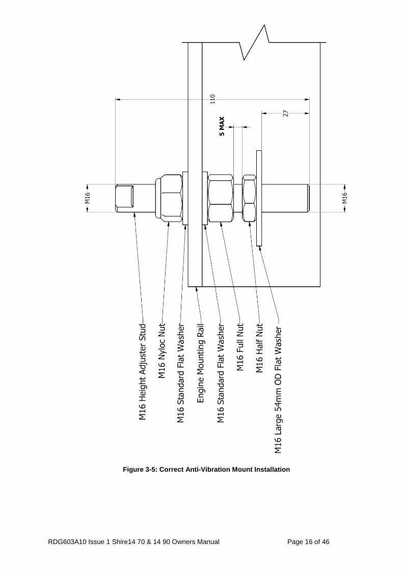
Figure 3-5: Correct Anti-Vibration Mount Installation
RDG603A10 Issue 1 Shire14 70 & 14 90 Owners Manual Page 17 of 46
10. Engine Alignment
The gearbox output shaft flange and propeller shaft input flange must be almost
perfectly aligned. A maximum of 0.05mm (0.002") misalignment in any plane is
acceptable. Ensure alignment is rechecked after the first 4 hours of running, at the
end of the first month and annually thereafter.
If the engine is out of alignment it will result in excessive vibration and possible
damage to the stern tube and propeller shaft.
Boats that are fitted with fully flexible drive couplings should still have the engine and
shaft alignment as close as possible. A dummy shaft may be required for this
purpose.
(Note: some types of flexible shaft couplings require the input and output to be
misaligned, check with the coupling manufacturer’s installation instructions).
11. Electrics
WARNING: Fit and tension domestic alternator belt, only when domestic battery bank has been
connected to domestic alternator.
Do not attach any part, hose or cable to the engine wiring harness. There is a
warning label attached to the harness to remind you of this.
Connect the wiring extension harness multi plug to the panel plug, and the other end
to the engine.
Connect the start battery positive cable to the engine starter motor solenoid terminal.
Starter motor battery cable size to be a minimum of 50mm2.
Shire 70 - Connect the domestic battery positive cable to the 240 Amp Alternator
“Pos out” terminal (see wiring diagram). This ensures that the 50A alternator
charges the start battery and the 240A alternator charges the domestic battery. Twin
alternators remove the requirement for a split charging system or relay.
Shire 90 – Connect the domestic battery positive cable to the 120Amp alternator B+
terminal (see wiring diagram). This ensures that the 140Amp alternator charges the
start battery. The blue link wire between the 120A Alternator B+ terminal or 160A
“pos out” terminal and the starter motor solenoid must be removed when the
domestic battery is connected.
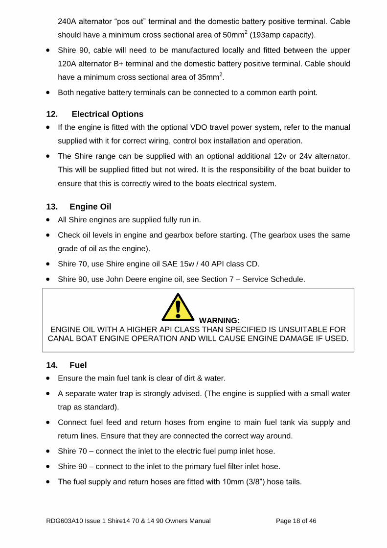
Shire 70, cable will need to be manufactured locally and fitted between the lower
RDG603A10 Issue 1 Shire14 70 & 14 90 Owners Manual Page 18 of 46
240A alternator “pos out” terminal and the domestic battery positive terminal. Cable
should have a minimum cross sectional area of 50mm2 (193amp capacity).
Shire 90, cable will need to be manufactured locally and fitted between the upper
120A alternator B+ terminal and the domestic battery positive terminal. Cable should
have a minimum cross sectional area of 35mm2.
Both negative battery terminals can be connected to a common earth point.
12. Electrical Options
If the engine is fitted with the optional VDO travel power system, refer to the manual
supplied with it for correct wiring, control box installation and operation.
The Shire range can be supplied with an optional additional 12v or 24v alternator.
This will be supplied fitted but not wired. It is the responsibility of the boat builder to
ensure that this is correctly wired to the boats electrical system.
13. Engine Oil
All Shire engines are supplied fully run in.
Check oil levels in engine and gearbox before starting. (The gearbox uses the same
grade of oil as the engine).
Shire 70, use Shire engine oil SAE 15w / 40 API class CD.
Shire 90, use John Deere engine oil, see Section 7 – Service Schedule.
WARNING: ENGINE OIL WITH A HIGHER API CLASS THAN SPECIFIED IS UNSUITABLE FOR
CANAL BOAT ENGINE OPERATION AND WILL CAUSE ENGINE DAMAGE IF USED.
14. Fuel
Ensure the main fuel tank is clear of dirt & water.
A separate water trap is strongly advised. (The engine is supplied with a small water
trap as standard).
Connect fuel feed and return hoses from engine to main fuel tank via supply and
return lines. Ensure that they are connected the correct way around.
Shire 70 – connect the inlet to the electric fuel pump inlet hose.
Shire 90 – connect to the inlet to the primary fuel filter inlet hose.
The fuel supply and return hoses are fitted with 10mm (3/8”) hose tails.
RDG603A10 Issue 1 Shire14 70 & 14 90 Owners Manual Page 19 of 46
The engine hoses should have sufficient slack to absorb engine movement without
placing strain on the hoses, and be securely clipped to prevent accidental damage
and chafing.
Initially fill the fuel system loosening the bleed bolt on the top of the primary fuel
filter/water trap. For Shire 70, turn on the ignition to operate the electric fuel pump.
For Shire 90, pump the primer on the primary filter. Close when fuel begins to flow
clearly (no bubbles). It is rarely necessary to bleed the injection pump or injectors
upon installation as the engine will already have fuel in it from the engine run-in and
test procedure.
15. Coolant
Yanmar (Shire 70) recommend a prepared coolant mix of 50% clean tap water and
50% antifreeze, John Deere (Shire 90) recommend that Coolguard must be used
(see Section 7 – Service Schedule). This is already mixed and must not have water
added to it.
Open the calorifier taps (where fitted) to fill the calorifier system and displace air.
To fill the cooling system for the first time. Fill the skin tank via the inlet hose
connection or filler plug if fitted.
Fill engine through the white plastic expansion bottle.
N.B. After running the engine for the first time, monitor the water level frequently as
trapped air bubbles may be expelled. Top up the system as necessary.
16. Calorifier
The temperature of coolant flowing to the calorifier from the engine can be between
85°C-90°C. A blender valve must be incorporated in the calorifier/hot water system
outlet to lower the hot water temperature for domestic use.
RDG603A10 Issue 1 Shire14 70 & 14 90 Owners Manual Page 20 of 46
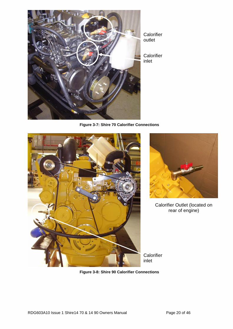
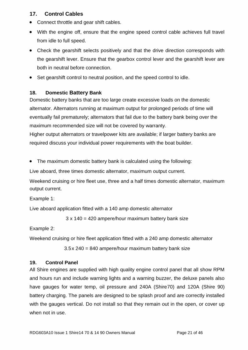
Figure 3-7: Shire 70 Calorifier Connections
Figure 3-8: Shire 90 Calorifier Connections
Calorifier inlet
Calorifier outlet
Calorifier inlet
Calorifier Outlet (located on rear of engine)
RDG603A10 Issue 1 Shire14 70 & 14 90 Owners Manual Page 21 of 46
17. Control Cables
Connect throttle and gear shift cables.
With the engine off, ensure that the engine speed control cable achieves full travel
from idle to full speed.
Check the gearshift selects positively and that the drive direction corresponds with
the gearshift lever. Ensure that the gearbox control lever and the gearshift lever are
both in neutral before connection.
Set gearshift control to neutral position, and the speed control to idle.
18. Domestic Battery Bank
Domestic battery banks that are too large create excessive loads on the domestic
alternator. Alternators running at maximum output for prolonged periods of time will
eventually fail prematurely; alternators that fail due to the battery bank being over the
maximum recommended size will not be covered by warranty.
Higher output alternators or travelpower kits are available; if larger battery banks are
required discuss your individual power requirements with the boat builder.
The maximum domestic battery bank is calculated using the following:
Live aboard, three times domestic alternator, maximum output current.
Weekend cruising or hire fleet use, three and a half times domestic alternator, maximum
output current.
Example 1:
Live aboard application fitted with a 140 amp domestic alternator
3 x 140 = 420 ampere/hour maximum battery bank size
Example 2:
Weekend cruising or hire fleet application fitted with a 240 amp domestic alternator
3.5 x 240 = 840 ampere/hour maximum battery bank size
19. Control Panel
All Shire engines are supplied with high quality engine control panel that all show RPM
and hours run and include warning lights and a warning buzzer, the deluxe panels also
have gauges for water temp, oil pressure and 240A (Shire70) and 120A (Shire 90)
battery charging. The panels are designed to be splash proof and are correctly installed
with the gauges vertical. Do not install so that they remain out in the open, or cover up
when not in use.
RDG603A10 Issue 1 Shire14 70 & 14 90 Owners Manual Page 22 of 46
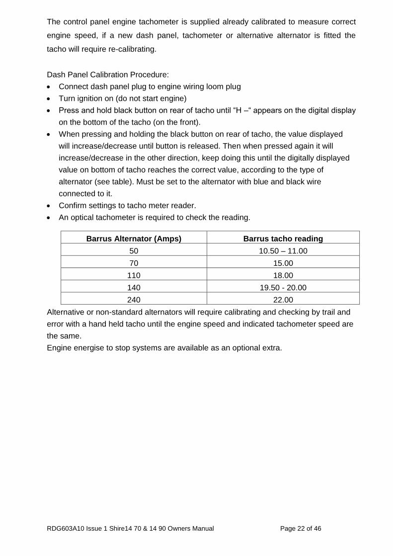
The control panel engine tachometer is supplied already calibrated to measure correct
engine speed, if a new dash panel, tachometer or alternative alternator is fitted the
tacho will require re-calibrating.
Dash Panel Calibration Procedure:
Connect dash panel plug to engine wiring loom plug
Turn ignition on (do not start engine)
Press and hold black button on rear of tacho until “H –“ appears on the digital display
on the bottom of the tacho (on the front).
When pressing and holding the black button on rear of tacho, the value displayed
will increase/decrease until button is released. Then when pressed again it will
increase/decrease in the other direction, keep doing this until the digitally displayed
value on bottom of tacho reaches the correct value, according to the type of
alternator (see table). Must be set to the alternator with blue and black wire
connected to it.
Confirm settings to tacho meter reader.
An optical tachometer is required to check the reading.
Barrus Alternator (Amps) Barrus tacho reading
50 10.50 – 11.00
70 15.00
110 18.00
140 19.50 - 20.00
240 22.00
Alternative or non-standard alternators will require calibrating and checking by trail and
error with a hand held tacho until the engine speed and indicated tachometer speed are
the same.
Engine energise to stop systems are available as an optional extra.
RDG603A10 Issue 1 Shire14 70 & 14 90 Owners Manual Page 23 of 46
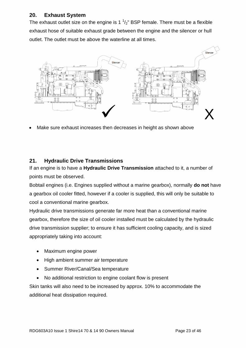
20. Exhaust System
The exhaust outlet size on the engine is 1 1/2" BSP female. There must be a flexible
exhaust hose of suitable exhaust grade between the engine and the silencer or hull
outlet. The outlet must be above the waterline at all times.
Make sure exhaust increases then decreases in height as shown above
21. Hydraulic Drive Transmissions
If an engine is to have a Hydraulic Drive Transmission attached to it, a number of
points must be observed.
Bobtail engines (i.e. Engines supplied without a marine gearbox), normally do not have
a gearbox oil cooler fitted, however if a cooler is supplied, this will only be suitable to
cool a conventional marine gearbox.
Hydraulic drive transmissions generate far more heat than a conventional marine
gearbox, therefore the size of oil cooler installed must be calculated by the hydraulic
drive transmission supplier; to ensure it has sufficient cooling capacity, and is sized
appropriately taking into account:
Maximum engine power
High ambient summer air temperature
Summer River/Canal/Sea temperature
No additional restriction to engine coolant flow is present
Skin tanks will also need to be increased by approx. 10% to accommodate the
additional heat dissipation required.
X
RDG603A10 Issue 1 Shire14 70 & 14 90 Owners Manual Page 24 of 46
22. Hydraulic Pump Drive (Shire 70)
For SAE type pump (9T). If a hydraulic pump is required to drive items such as bow thrusters or hydraulic winches then the following parts are required to enable drive to be taken from the engine power take off. Part No. 129980-26220 incorporates:
Applicable cover: 121023-26070
Packing:121023-26061
Bearings: 129900-26250 x 2pcs (included in the specialised gear case)
For high discharge volume: above 20cc/rev Ratio: 1.231
RDG603A10 Issue 1 Shire14 70 & 14 90 Owners Manual Page 25 of 46
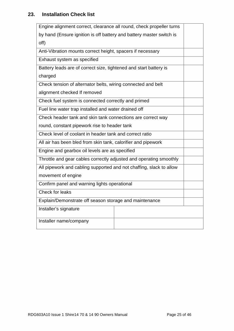
23. Installation Check list
Engine alignment correct, clearance all round, check propeller turns
by hand (Ensure ignition is off battery and battery master switch is
off)
Anti-Vibration mounts correct height, spacers if necessary
Exhaust system as specified
Battery leads are of correct size, tightened and start battery is
charged
Check tension of alternator belts, wiring connected and belt
alignment checked If removed
Check fuel system is connected correctly and primed
Fuel line water trap installed and water drained off
Check header tank and skin tank connections are correct way
round, constant pipework rise to header tank
Check level of coolant in header tank and correct ratio
All air has been bled from skin tank, calorifier and pipework
Engine and gearbox oil levels are as specified
Throttle and gear cables correctly adjusted and operating smoothly
All pipework and cabling supported and not chaffing, slack to allow
movement of engine
Confirm panel and warning lights operational
Check for leaks
Explain/Demonstrate off season storage and maintenance
Installer’s signature
Installer name/company
RDG603A10 Issue 1 Shire14 70 & 14 90 Owners Manual Page 26 of 46
SECTION 4 - Operation
1. Starting The Engine For The First Time
Remove the ignition key.
Ensure oil and coolant levels are checked.
Ensure both engine and domestic batteries are connected or the blue link wire is in
place (Shire 90 only).
Check all connections and mountings are tight.
Ensure the red protection cap is removed from the air filter inlet.
2. Starting Procedure
Note: Shire engines do not have a cold start function as standard. Therefore the glow
plug light will not illuminate.
Ensure the gearshift control is set to neutral, and that persons are clear of any
moving parts.
Insert key.
Ensure the domestic battery isolator is turned to the on position before starting the
engine, failure to do so may damage the domestic alternator.
Turn key to first position, on.
Observe warning lights and gauges on panel.
Listen for warning buzzer.
Turn key to second position, start, and hold to crank.
Crank the engine for no more than 15 seconds.
Immediately on engine start, release key.
Key will return to first position, on.
The warning buzzer will stop and on the deluxe panel the oil pressure gauge will
show an oil pressure of 3-4 bar [44-58 psi].
Should any warning light fail to go out or there is no reading on the oil pressure
gauge, the buzzer will continue sounding. In this case stop the engine immediately
and check the relevant system. (Note if the charge light does not go out increase the
engine speed briefly).
Stop engine immediately if any abnormal noises are detected.
Visually check the engine for oil, fuel and coolant leaks, (after initial start up and at
regular intervals, N.B. engine must be stopped to carry out this check).
3. Stopping Procedure
Move speed control lever to idle position.
Turn key to off position.
RDG603A10 Issue 1 Shire14 70 & 14 90 Owners Manual Page 27 of 46
4. Full Load Running
Running diesel engines near their rated output (maximum load) regularly will
disperse accumulated carbon and condensation enhancing engine life and reducing
emissions.
Running the engine at, or near maximum speed whilst in gear may not be possible
on inland waterways with speed limits in place. This will have to be carried out
whilst moored up. Ensure that the mooring ropes and posts are strong enough to
allow this, and that the water is deep enough not to damage the propeller. It is
recommended that the engine is run at or near full load for 15 minutes (maximum
engine speed, in gear) every 50 hours.
5. Refuelling
The fuel type for all Shire canal boat engines is diesel. DO NOT USE BIODIESEL
Please note that when the vessel is to be left for any period of time the fuel tank
should be left full to eliminate the build up of condensation and water in the tank.
6. Diesel Fuel Additive
The use of diesel fuel additive is strongly recommended on Shanks & Shire engines.
The quality of the fuel available when cruising is often unknown; also the fuel may
have been in storage for long periods of time. The use of additives will ensure that
your engine fuel injection system is in top condition, which should result in many
years of smooth reliable operation without the cost and inconvenience of expensive
breakdowns due to poor quality fuel. It has also been found that improvements in
fuel consumption and startability are an added benefit of using this product.
Diesel fuel additive is available from your Shanks or Shire dealer in a handy 375 ml
container, part number RDG80210219.
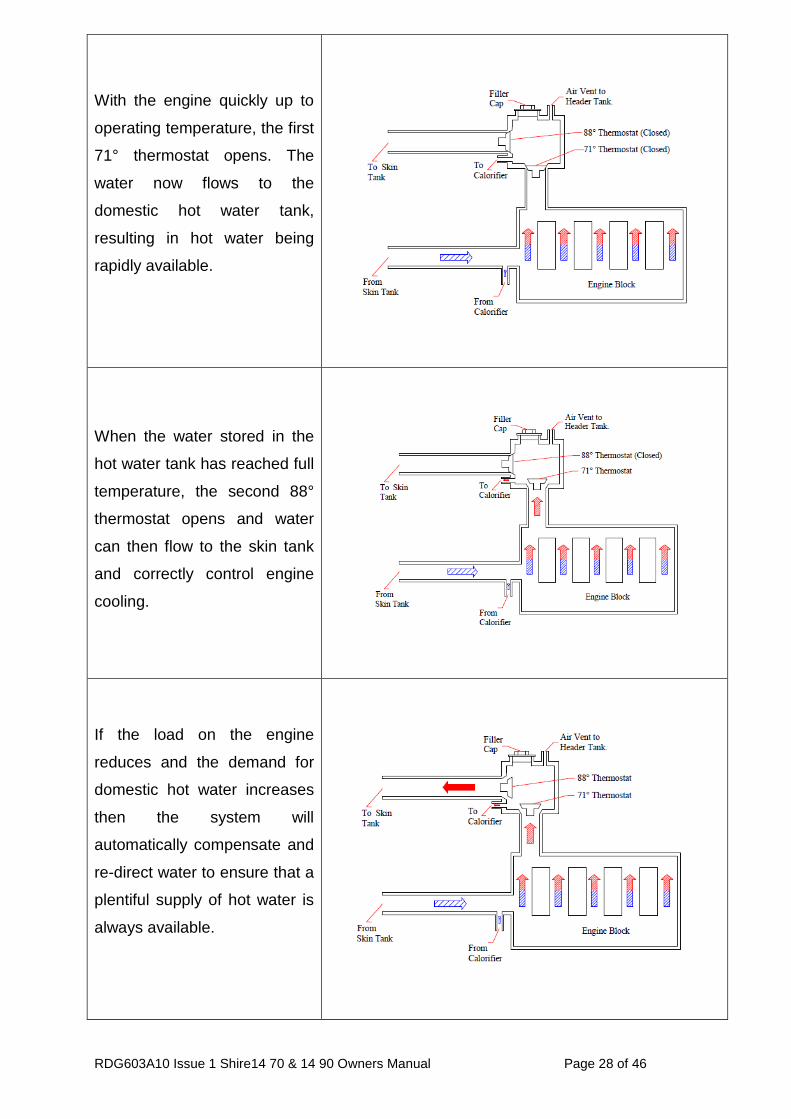
7. Twin Thermostats
The twin thermostat design is a feature unique to the Shire canal boat engine range
(excludes Shire 90). The diagrams on the following page show the operation of the
cooling system.
RDG603A10 Issue 1 Shire14 70 & 14 90 Owners Manual Page 28 of 46
With the engine quickly up to
operating temperature, the first
71° thermostat opens. The
water now flows to the
domestic hot water tank,
resulting in hot water being
rapidly available.
When the water stored in the
hot water tank has reached full
temperature, the second 88°
thermostat opens and water
can then flow to the skin tank
and correctly control engine
cooling.
If the load on the engine
reduces and the demand for
domestic hot water increases
then the system will
automatically compensate and
re-direct water to ensure that a
plentiful supply of hot water is
always available.
RDG603A10 Issue 1 Shire14 70 & 14 90 Owners Manual Page 29 of 46
8. Exhaust Back Pressure
The back pressure falls within the manufacturers recommended range when using the
exhaust system supplied with the engine.
SECTION 5 - Service Procedure
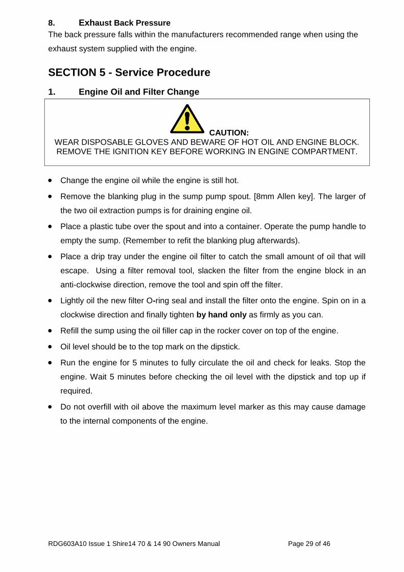
1. Engine Oil and Filter Change
CAUTION: WEAR DISPOSABLE GLOVES AND BEWARE OF HOT OIL AND ENGINE BLOCK. REMOVE THE IGNITION KEY BEFORE WORKING IN ENGINE COMPARTMENT.
Change the engine oil while the engine is still hot.
Remove the blanking plug in the sump pump spout. [8mm Allen key]. The larger of
the two oil extraction pumps is for draining engine oil.
Place a plastic tube over the spout and into a container. Operate the pump handle to
empty the sump. (Remember to refit the blanking plug afterwards).
Place a drip tray under the engine oil filter to catch the small amount of oil that will
escape. Using a filter removal tool, slacken the filter from the engine block in an
anti-clockwise direction, remove the tool and spin off the filter.
Lightly oil the new filter O-ring seal and install the filter onto the engine. Spin on in a
clockwise direction and finally tighten by hand only as firmly as you can.
Refill the sump using the oil filler cap in the rocker cover on top of the engine.
Oil level should be to the top mark on the dipstick.
Run the engine for 5 minutes to fully circulate the oil and check for leaks. Stop the
engine. Wait 5 minutes before checking the oil level with the dipstick and top up if
required.
Do not overfill with oil above the maximum level marker as this may cause damage
to the internal components of the engine.
RDG603A10 Issue 1 Shire14 70 & 14 90 Owners Manual Page 30 of 46
2. Air Filter Check & Change
CAUTION: WEAR DISPOSABLE GLOVES AND BEWARE OF HOT ENGINE BLOCK. REMOVE
THE IGNITION KEY BEFORE WORKING IN ENGINE COMPARTMENT.
Release the two spring clips, pull off the end cover to reveal the filter element. The
element simply pulls out. Note: the Shire 90 has an inner safety element fitted.
The air filter element is constructed from pleated paper; inspect it closely for dust or
dirt. The air filter cannot be cleaned and must be replaced when dirty. The engine
requires clean unrestricted air to run efficiently, failure to maintain the air filter could
result in smoke, increased fuel consumption and ultimately engine damage.
To fit the new element, slide the open end of the filter element into the main body;
gently push the element home until fully seated. Refit the end cover.
3. Gearbox Oil Change
CAUTION: WEAR DISPOSABLE GLOVES AND BEWARE OF HOT OIL AND GEARBOX CASING.
REMOVE THE IGNITION KEY, BEFORE WORKING IN ENGINE COMPARTMENT.
Change the gearbox oil while it is still hot. (Please refer to gearbox manual for more
information).
Remove the plug from the gearbox drain pump; this is the smaller of the two pumps
(6mm Allen key).
Pump contents in a suitable container (not less than 2.2 litres).
Refill the gearbox with oil to the upper mark on the dipstick. Screw dipstick in fully to
establish level. The gearbox uses the same grade of oil as the engine. Refer to
PRM manual for more details.
Section 6 – Service Parts contains details of oil specifications.
Do not overfill gearbox as this can damage the internal components.
RDG603A10 Issue 1 Shire14 70 & 14 90 Owners Manual Page 31 of 46
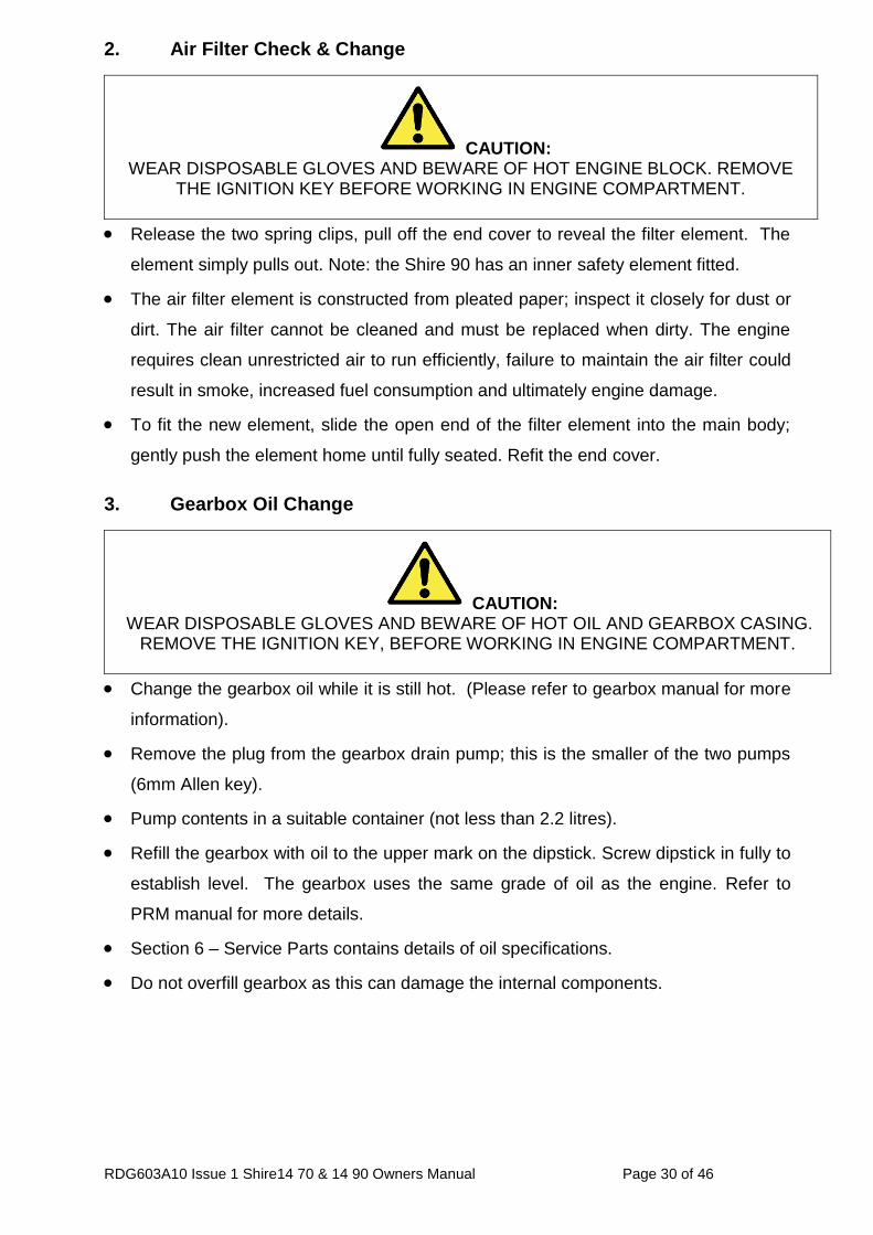
PRM 260 gearbox filler circled in the picture below.
4. Disposal of Oil and Related Items
Please dispose of used oil and oil filters safely with due regard for the environment,
and take to your local waste oil disposal point.
Do not allow oil or contaminated parts enter the inland waterway system.
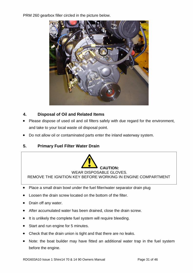
5. Primary Fuel Filter Water Drain
CAUTION: WEAR DISPOSABLE GLOVES.
REMOVE THE IGNITION KEY BEFORE WORKING IN ENGINE COMPARTMENT
Place a small drain bowl under the fuel filter/water separator drain plug
Loosen the drain screw located on the bottom of the filter.
Drain off any water.
After accumulated water has been drained, close the drain screw.
It is unlikely the complete fuel system will require bleeding.
Start and run engine for 5 minutes.
Check that the drain union is tight and that there are no leaks.
Note: the boat builder may have fitted an additional water trap in the fuel system
before the engine.
RDG603A10 Issue 1 Shire14 70 & 14 90 Owners Manual Page 32 of 46
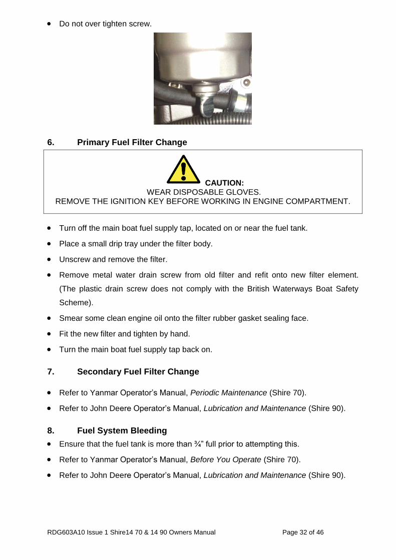
Do not over tighten screw.
6. Primary Fuel Filter Change
Turn off the main boat fuel supply tap, located on or near the fuel tank.
Place a small drip tray under the filter body.
Unscrew and remove the filter.
Remove metal water drain screw from old filter and refit onto new filter element.
(The plastic drain screw does not comply with the British Waterways Boat Safety
Scheme).
Smear some clean engine oil onto the filter rubber gasket sealing face.
Fit the new filter and tighten by hand.
Turn the main boat fuel supply tap back on.
7. Secondary Fuel Filter Change
Refer to Yanmar Operator’s Manual, Periodic Maintenance (Shire 70).
Refer to John Deere Operator’s Manual, Lubrication and Maintenance (Shire 90).
8. Fuel System Bleeding
Ensure that the fuel tank is more than ¾” full prior to attempting this.
Refer to Yanmar Operator’s Manual, Before You Operate (Shire 70).
Refer to John Deere Operator’s Manual, Lubrication and Maintenance (Shire 90).
CAUTION: WEAR DISPOSABLE GLOVES.
REMOVE THE IGNITION KEY BEFORE WORKING IN ENGINE COMPARTMENT.
RDG603A10 Issue 1 Shire14 70 & 14 90 Owners Manual Page 33 of 46
9. Cooling System
WARNING: DO NOT CHECK THE COOLANT LEVEL WHEN THE ENGINE IS HOT. REMOVE THE
IGNITION KEY BEFORE WORKING IN ENGINE COMPARTMENT.
To check the coolant level, ensure that the engine has been shut down for at least
half an hour.
The coolant level can be checked visually and should be between the two level
marks moulded on to the white, plastic expansion tank.
If required, top up the level with coolant (50% clean tap water and 50% ethylene
glycol based anti-freeze) through the expansion tank filler cap. (Shire 70 and Shire
90 use John Deere, coolguard neat)
Do not use water only to top up mix as this weakens the coolant mix, reducing the
level of frost protection and anti-corrosion protection of the coolant.
RDG603A10 Issue 1 Shire14 70 & 14 90 Owners Manual Page 34 of 46
10. Belt Adjustment
CAUTION: REMOVE THE IGNITION KEY BEFORE WORKING IN ENGINE COMPARTMENT.
Depress the longest run of the drive belt to be checked. If the travel exceeds 15 -
20mm using hard finger pressure, the belt needs re-tensioning.
Loosen the upper adjuster bolts on the alternator, and the lower mounting pivot nut
and bolt, either pull out using hand pressure or use the tensioning screw, depending
on which alternator is fitted.
Pull the alternator away from the engine to tighten the belt.
Hold the alternator in position and re-tighten all the bolts.
Note: 1 – If the belts are over tightened alternator bearing failure will occur.
2 – Shire 90: 140Amp and 120Amp alternator belt is self-adjusting.
11. Belt Maintenance
Do not allow oil to contact the belt, oil attacks the construction of the belt, reduces
the drive efficiency and will ultimately cause it to fail prematurely.
Replace the belt if it cracks, splits, or as the adjustment nears the limit of its travel.
Note: Some boat builders may remove one or more of the alternators during the
installation of the engine. It is essential that when the alternators are refitted that the
alignment is perfect or premature belt wear will occur.
12. Belt Replacement
CAUTION: REMOVE THE IGNITION KEY BEFORE WORKING IN ENGINE COMPARTMENT.
Shire 70:
Ensure that you have the correct belts before starting this procedure. Some
customers may have engines fitted with non-standard optional alternators, which
may not have the standard belts listed. Make a note of the belt sizes on delivery.
Loosen the top adjuster bolts, and the lower mounting pivot nut and bolt.
Push the alternator towards the engine to loosen the belt.
Remove the belt.
RDG603A10 Issue 1 Shire14 70 & 14 90 Owners Manual Page 35 of 46
Hold the belt in position over the top alternator pulley, rotate the engine, if required,
by hand, to guide the new belt into the “vee”.
Re - tension the belt as above.
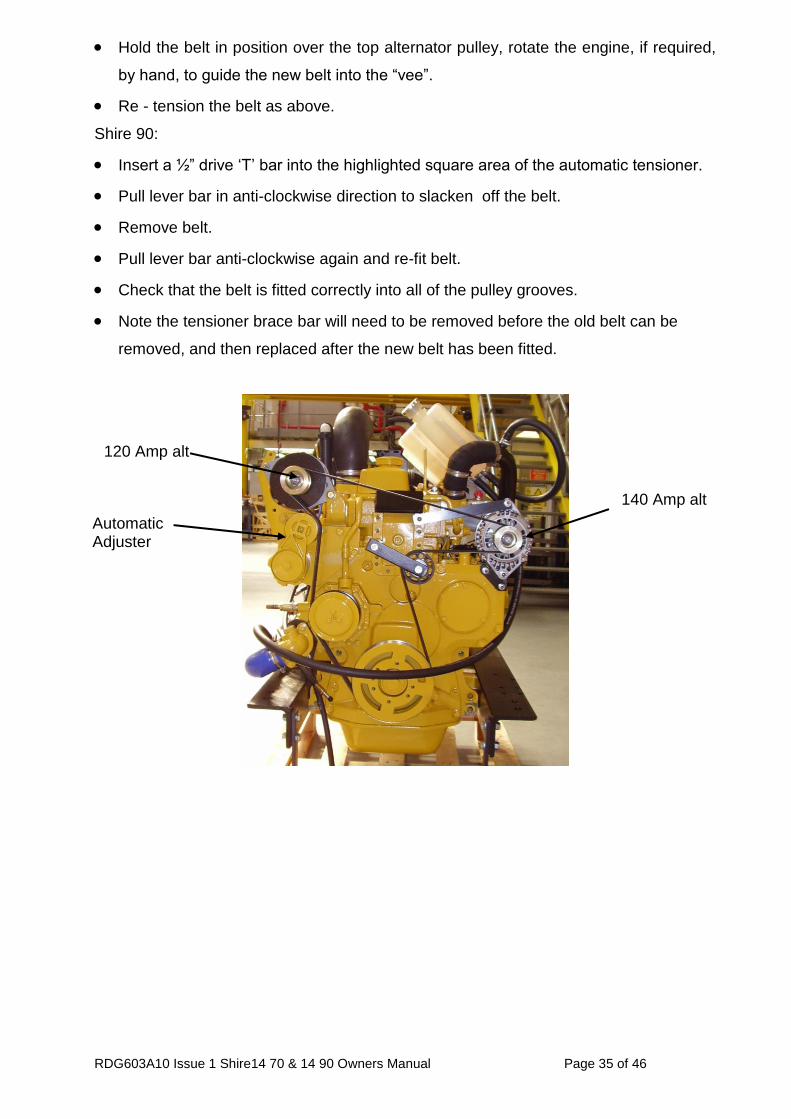
Shire 90:
Insert a ½” drive ‘T’ bar into the highlighted square area of the automatic tensioner.
Pull lever bar in anti-clockwise direction to slacken off the belt.
Remove belt.
Pull lever bar anti-clockwise again and re-fit belt.
Check that the belt is fitted correctly into all of the pulley grooves.
Note the tensioner brace bar will need to be removed before the old belt can be
removed, and then replaced after the new belt has been fitted.
120 Amp alt
Automatic Adjuster
140 Amp alt
RDG603A10 Issue 1 Shire14 70 & 14 90 Owners Manual Page 36 of 46
13. Deluxe Panel Maintenance
CAUTION: REMOVE THE IGNITION KEY & TURN BATTERY ISOLATOR SWITCHES OFF
BEFORE WORKING IN THE ENGINE COMPARTMENT.
Warning Light Bulb replacement
Release the panel from its mounting
1. To replace an illumination bulb.
a. The bulbs are accessible from the rear of the panel. This can be gently
removed by pulling off the wires, unscrewing the nut and pulling out the bulb
housing from the panel.
2. To replace any gauge
a. The gauges are accessible from rear of the panel. Unplug the wire
connectors, unscrew and pull the gauge out from the panel.
3. Periodically squirt a lubricant in to the key switch slot with key removed (a lubricant
such as WD40 – with silicon, other lubricants are available). Then with the battery
master switch turned off operate key switch a couple of times to ensure lubricant
works in to mechanism.
RDG603A10 Issue 1 Shire14 70 & 14 90 Owners Manual Page 37 of 46
SECTION 6 - Service Parts
Shire 70
Spare Part Description Part No.
Primary Fuel Filter Element RDG 9188346
Secondary Fuel Filter Element 119802-55800
50A Alternator Belt GB/T12732-1996
240A Alternator Belt RDG 0047511
Air Filter Element RDG 6613
Oil Filter 129150 - 35153
Engine Oil RDG6110 (5 litre container)
3.5 & 5 kW Alternator Belt (Option) RDG 0047600
8 kW Alternator Belt (Option) RDG 0047601
Shire 90
Spare Part Description Part No.
Primary Fuel Filter Element RDG 9188346
Secondary Fuel Filter Element RE62418
Inner Air Filter Element RDG 6651
Outer Air Filter Element RDG 6650
Oil Filter RE504836
Alternator Main Drive Belt RDG 0047272
3.5 kW Alternator Belt (Option) RDG 0047581
5 kW Alternator Belt (Option) RDG 6816
8 kW Alternator Belt (Option) RDG 6830
Fuses
The electrical system is fitted with three or four blade type fuses,
Dash Panel supply 15 amp (RDG3245)
Engine stop control system 40 amp (RDG3246)
Engine start control system 20 amp (RDG1152)
Dash panel live 15 amp (RDG3245) Shire 70 only
Contact a Shire or Yanmar Marine dealer for Spare Parts (see Section 9 – Dealer List).
RDG603A10 Issue 1 Shire14 70 & 14 90 Owners Manual Page 38 of 46
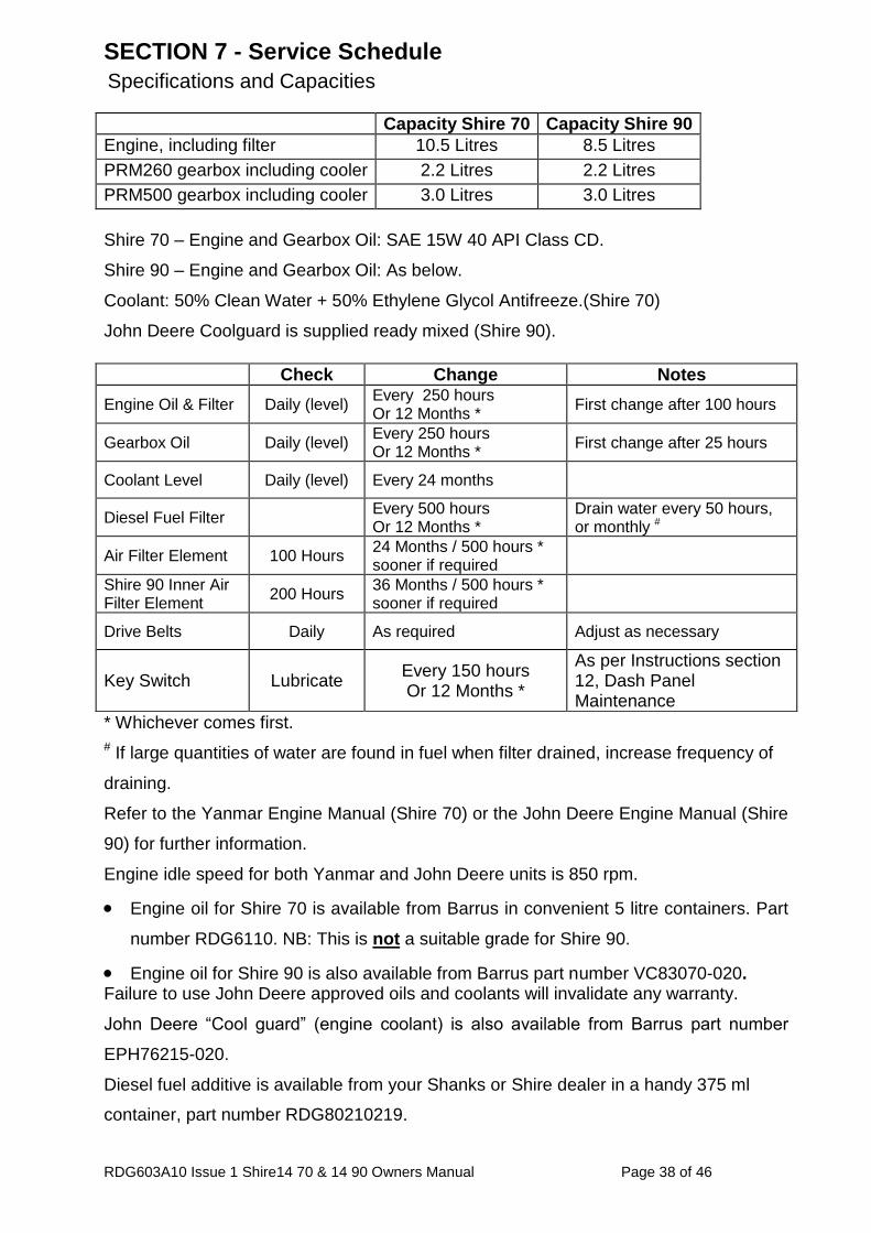
SECTION 7 - Service Schedule
Specifications and Capacities
Capacity Shire 70 Capacity Shire 90
Engine, including filter 10.5 Litres 8.5 Litres
PRM260 gearbox including cooler 2.2 Litres 2.2 Litres
PRM500 gearbox including cooler 3.0 Litres 3.0 Litres
Shire 70 – Engine and Gearbox Oil: SAE 15W 40 API Class CD.
Shire 90 – Engine and Gearbox Oil: As below.
Coolant: 50% Clean Water + 50% Ethylene Glycol Antifreeze.(Shire 70)
John Deere Coolguard is supplied ready mixed (Shire 90).
* Whichever comes first.
# If large quantities of water are found in fuel when filter drained, increase frequency of
draining.
Refer to the Yanmar Engine Manual (Shire 70) or the John Deere Engine Manual (Shire
90) for further information.
Engine idle speed for both Yanmar and John Deere units is 850 rpm.
Engine oil for Shire 70 is available from Barrus in convenient 5 litre containers. Part
number RDG6110. NB: This is not a suitable grade for Shire 90.
Engine oil for Shire 90 is also available from Barrus part number VC83070-020. Failure to use John Deere approved oils and coolants will invalidate any warranty.
John Deere “Cool guard” (engine coolant) is also available from Barrus part number
EPH76215-020.
Diesel fuel additive is available from your Shanks or Shire dealer in a handy 375 ml
container, part number RDG80210219.
Check Change Notes
Engine Oil & Filter Daily (level) Every 250 hours Or 12 Months *
First change after 100 hours
Gearbox Oil Daily (level) Every 250 hours Or 12 Months *
First change after 25 hours
Coolant Level Daily (level) Every 24 months
Diesel Fuel Filter Every 500 hours Or 12 Months *
Drain water every 50 hours, or monthly #
Air Filter Element 100 Hours 24 Months / 500 hours * sooner if required
Shire 90 Inner Air Filter Element
200 Hours 36 Months / 500 hours * sooner if required
Drive Belts Daily As required Adjust as necessary
Key Switch Lubricate Every 150 hours Or 12 Months *
As per Instructions section 12, Dash Panel Maintenance
RDG603A10 Issue 1 Shire14 70 & 14 90 Owners Manual
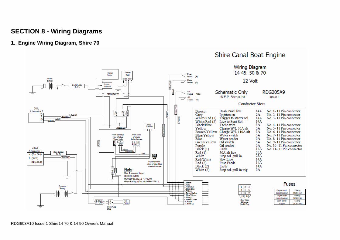
SECTION 8 - Wiring Diagrams
1. Engine Wiring Diagram, Shire 70
RDG603A10 Issue 1 Shire14 70 & 14 90 Owners Manual Page 40 of 46
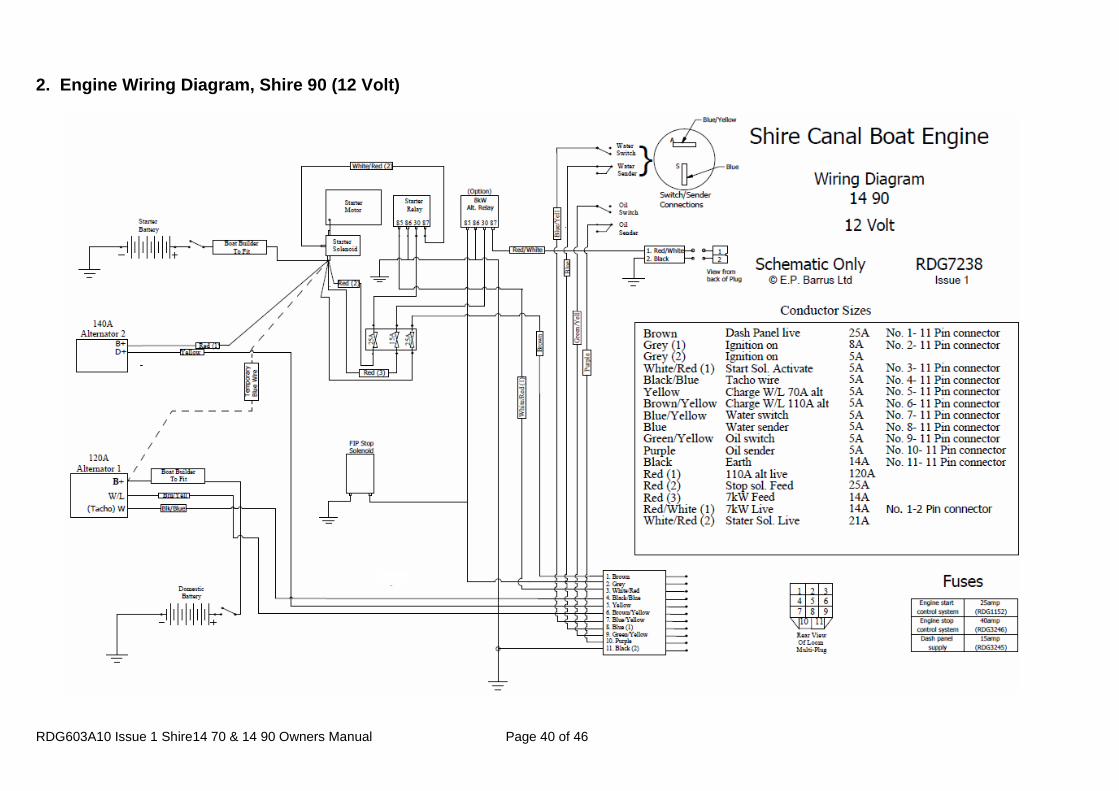
2. Engine Wiring Diagram, Shire 90 (12 Volt)
RDG603A10 Issue 1 Shire14 70 & 14 90 Owners Manual Page 41 of 46
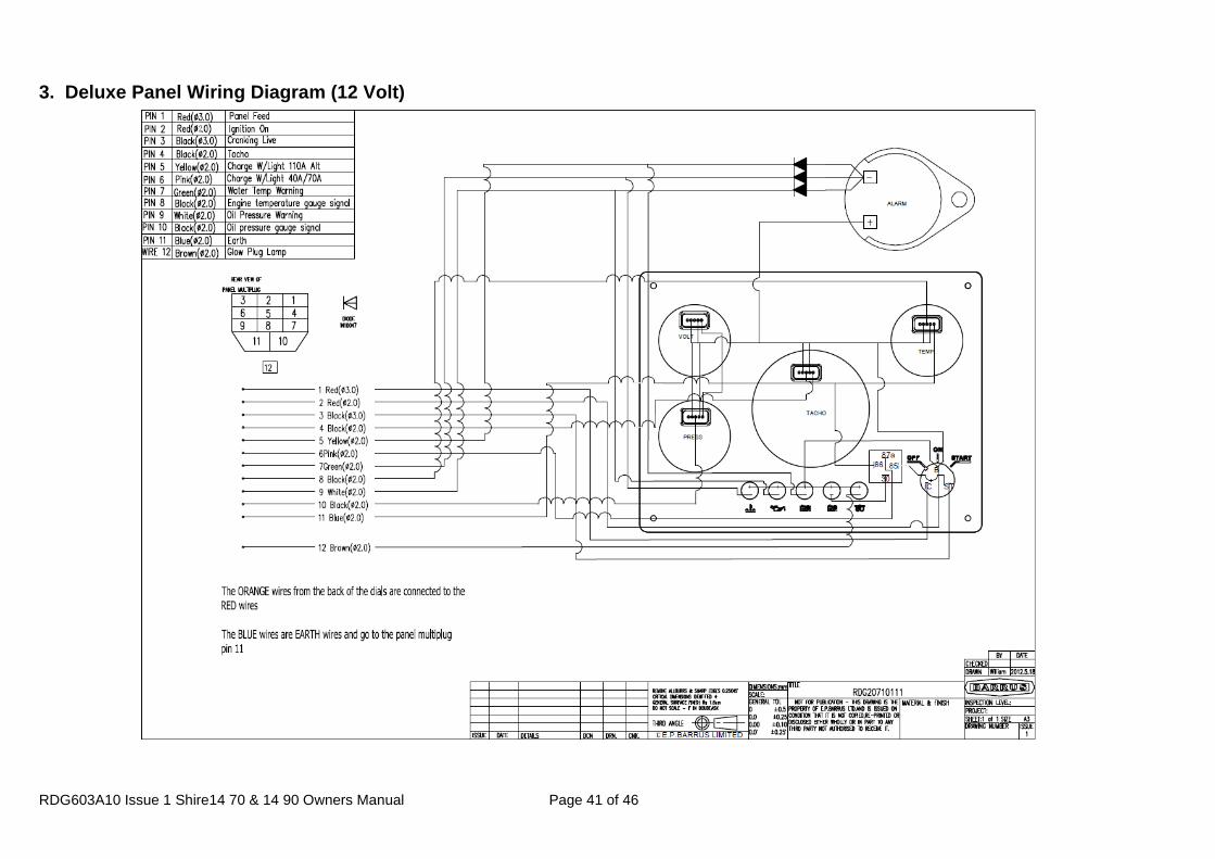
3. Deluxe Panel Wiring Diagram (12 Volt)
RDG603A10 Issue 1 Shire14 70 & 14 90 Owners Manual
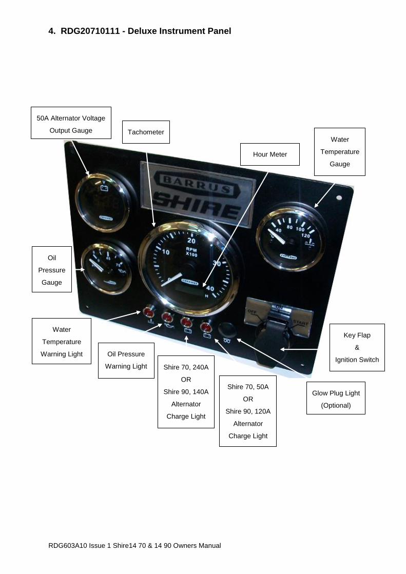
4. RDG20710111 - Deluxe Instrument Panel
Shire 70, 50A
OR
Shire 90, 120A
Alternator
Charge Light
Shire 70, 240A
OR
Shire 90, 140A
Alternator
Charge Light
Oil Pressure
Warning Light
Water
Temperature
Warning Light
Glow Plug Light
(Optional)
Key Flap
&
Ignition Switch
Water
Temperature
Gauge
Hour Meter
Tachometer
50A Alternator Voltage
Output Gauge
Oil
Pressure
Gauge
RDG603A10 Issue 1 Shire14 70 & 14 90 Owners Manual Page 43 of 46
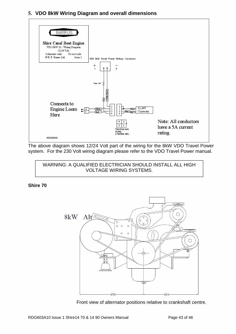
5. VDO 8kW Wiring Diagram and overall dimensions
The above diagram shows 12/24 Volt part of the wiring for the 8kW VDO Travel Power system. For the 230 Volt wiring diagram please refer to the VDO Travel Power manual.
Shire 70
Front view of alternator positions relative to crankshaft centre.
WARNING: A QUALIFIED ELECTRICIAN SHOULD INSTALL ALL HIGH VOLTAGE WIRING SYSTEMS.
RDG603A10 Issue 1 Shire14 70 & 14 90 Owners Manual Page 44 of 46
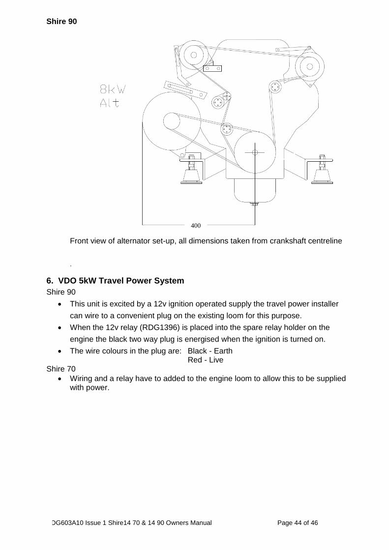
Shire 90
Front view of alternator set-up, all dimensions taken from crankshaft centreline
.
6. VDO 5kW Travel Power System
Shire 90
This unit is excited by a 12v ignition operated supply the travel power installer
can wire to a convenient plug on the existing loom for this purpose.
When the 12v relay (RDG1396) is placed into the spare relay holder on the
engine the black two way plug is energised when the ignition is turned on.
The wire colours in the plug are: Black - Earth Red - Live
Shire 70
Wiring and a relay have to added to the engine loom to allow this to be supplied with power.
400
RDG603A10 Issue 1 Shire14 70 & 14 90 Owners Manual Page 45 of 46
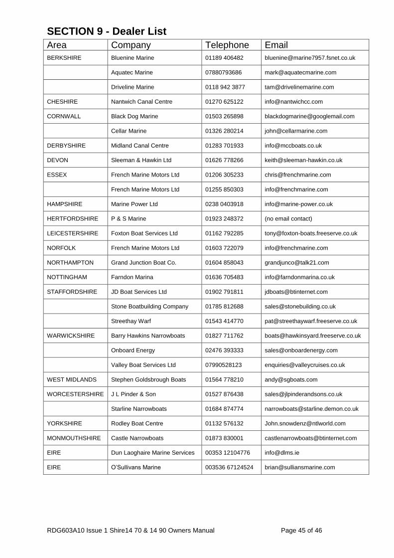
SECTION 9 - Dealer List
Area Company Telephone Email
BERKSHIRE Bluenine Marine 01189 406482 [email protected]
Aquatec Marine 07880793686 [email protected]
Driveline Marine 0118 942 3877 [email protected]
CHESHIRE Nantwich Canal Centre 01270 625122 [email protected]
CORNWALL Black Dog Marine 01503 265898 [email protected]
Cellar Marine 01326 280214 [email protected]
DERBYSHIRE Midland Canal Centre 01283 701933 [email protected]
DEVON Sleeman & Hawkin Ltd 01626 778266 [email protected]
ESSEX French Marine Motors Ltd 01206 305233 [email protected]
French Marine Motors Ltd 01255 850303 [email protected]
HAMPSHIRE Marine Power Ltd 0238 0403918 [email protected]
HERTFORDSHIRE P & S Marine 01923 248372 (no email contact)
LEICESTERSHIRE Foxton Boat Services Ltd 01162 792285 [email protected]
NORFOLK French Marine Motors Ltd 01603 722079 [email protected]
NORTHAMPTON Grand Junction Boat Co. 01604 858043 [email protected]
NOTTINGHAM Farndon Marina 01636 705483 [email protected]
STAFFORDSHIRE JD Boat Services Ltd 01902 791811 [email protected]
Stone Boatbuilding Company 01785 812688 [email protected]
Streethay Warf 01543 414770 [email protected]
WARWICKSHIRE Barry Hawkins Narrowboats 01827 711762 [email protected]
Onboard Energy 02476 393333 [email protected]
Valley Boat Services Ltd 07990528123 [email protected]
WEST MIDLANDS Stephen Goldsbrough Boats 01564 778210 [email protected]
WORCESTERSHIRE J L Pinder & Son 01527 876438 [email protected]
Starline Narrowboats 01684 874774 [email protected]
YORKSHIRE Rodley Boat Centre 01132 576132 [email protected]
MONMOUTHSHIRE Castle Narrowboats 01873 830001 [email protected]
EIRE Dun Laoghaire Marine Services 00353 12104776 [email protected]
EIRE O’Sullivans Marine 003536 67124524 [email protected]
RDG603A10 Issue 1 Shire14 70 & 14 90 Owners Manual Page 46 of 46
e Record Card