Embed Size (px)
Citation preview
Shoemark, D. K., Avila Ibarra, A., Ross, J. F., Beesley, J. L., Bray, H.E. V., Mosayebi, M., Linden, N., Liverpool, T. B., McIntosh-Smith, S.N., Woolfson, D. N., & Sessions, R. B. (2018). The dynamicalinterplay between a megadalton peptide nanocage and solutesprobed by microsecond atomistic MD; Implications for design.Physical Chemistry Chemical Physics, 21(1), 137-147.https://doi.org/10.1039/c8cp06282j
Peer reviewed version
Link to published version (if available):10.1039/c8cp06282j
Link to publication record in Explore Bristol ResearchPDF-document
This is the author accepted manuscript (AAM). The final published version (version of record) is available onlinevia RSC at https://pubs.rsc.org/en/Content/ArticleLanding/2019/CP/C8CP06282J#!divAbstract . Please refer toany applicable terms of use of the publisher.
University of Bristol - Explore Bristol ResearchGeneral rights
This document is made available in accordance with publisher policies. Please cite only thepublished version using the reference above. Full terms of use are available:http://www.bristol.ac.uk/red/research-policy/pure/user-guides/ebr-terms/

Shoemark et al. Microsecond atomistic simulation of peptide nanocage 1
Supporting Information
The dynamical interplay between a megadalton peptide nanocage
and solutes probed by microsecond atomistic MD; implications for
design.
Deborah K. Shoemark1,2, Amaurys Avila-Ibarra1, James F. Ross3, Joseph L. Beesley3, Harriet E.V.
Bray3, Majid Mosayebi2,4, Noah Linden4, Tanniemola B. Liverpool2,4, Simon N. McIntosh-Smith5,
Derek N. Woolfson2,3*, Richard B. Sessions1,2*
1School of Biochemistry, Biomedical Sciences Building, University Walk, Bristol.BS8 1TD, UK., 2BrisSynBio,
Life Sciences Building, Tyndall Avenue, Bristol, BS8 1TQ UK., 3School of Chemistry, Cantock's Close, Bristol,
BS8 1TS. UK.,4School of Mathematics, University Walk, Bristol, BS8 1TW. UK., 5Computer Sciences, Merchant
Venturers’ Building, Woodland Road, Bristol. BS8 1UB. UK.
*To whom correspondence should be addressed:
[email protected]; 1School of Biochemistry, Biomedical Sciences Building, University Walk, Bristol BS8 1TD, UK. Tel: +44 (0) 117 3312146
[email protected]; School of Chemistry, University of Bristol, Bristol BS8 1TS, UK. Tel: +44 (0)117 95 46347
Shoemark et al. Microsecond atomistic simulation of peptide nanocage 2
SI-1 SAGE model construction. 3
SI-2 SAGE simulation setup and production 4
SI-2 Table 1 Molecular dynamics simulation trajectories acquired 4
SI-2 Table 2. Small molecules and proteins added to the longer trajectories 5
SI-3. Parallel performance 5
SI-4. Data analysis 6
SI-5 Gross structural changes of the SAGE in the simulations 6
SI-6 Simulations with solutes 8
SI-6.1 Ion passage in simulations 9
SI-6.2 Small molecule passage in simulations 10
SI-6.3 Heat-mapping protein solute contacts with SAGE 12
SI-6.4 Solute protein conformation and SAGE contact 18
SI-7 Experimental observations of “stickiness” of the parent-SAGE 21
SI-7.1 SAGE binding experimental Methods 21
SI-7.2 Experimental GFP binding to SAGE assemblies 22
SI-8 References 22

Shoemark et al. Microsecond atomistic simulation of peptide nanocage 3
SI-1. SAGE model construction.
Here we describe how the simplest model of the SAGE peptide nanostructure, comprised of
a single layer of peptides was built. In order to form a closed sphere from a predominantly
hexagonal (honeycomb) lattice of peptides 1-3 -we used the set of points on a sphere with
icosahedral symmetry based on the work of Harding, Sloane and Smith and comprised the
file http://neilsloane.com/ICOSC/icover.3.312.5.1.txt . A program was written to construct a
hexagonal closed net containing 12 pentagons and corresponding Chimera bild format file
(Figure SI.1).
Figure SI-1. Left: 312 points on a sphere (red). Left center: 1860 interpolated vertices (green); Right center: vertices connected by edges (blue). Right: displaying only the edges (the net).
Polymerizing the acidic and basic hubs (as shown in Figure 1) to form a closed structure with
all acidic and basic peptides matched requires at least one mixed hub at each of the 12
pentagons. This requirement is best illustrated by running a Monte Carlo simulation and
minimizing the objective function with a genetic algorithm where the objective is to minimize
the number of mismatched hubs. A program was written to perform this task and the output
with all pure acidic and basic hubs shows the line of non-matching hubs connecting pairs of
pentagons (SI-2 panel A). Converting the mismatched hubs (at least 36) to mixed hubs allows
perfect closure of the network (SI-2 panel B). The SAGE models were prepared by placing the
appropriate acidic, basic and mixed hubs at the vertices of the network shown in using another
bespoke program.

Shoemark et al. Microsecond atomistic simulation of peptide nanocage 4
SI-2. SAGE simulation setup and production
Sequence information.
The sequences used in these simulations correspond to three of the standard SAGE
constructs used in the Woolfson lab for biophysical and structural analysis towards medically
or industrially relevant applications.
Where Ac and nh2 refer to end capping N-terminal acetyl group and C-terminal amide groups
added to reflect the chemically synthesized experimental constructs.
SI-2 Table 1 Molecular dynamics simulation trajectories acquired
System Dimer N
in/out
Proteins
/small
molecules
Length
(µs) SAGE charge
Na+
Ions
Cl-
ions
Virtual
sites (H)
Parent-SAGE-dim-o out N 0.1 +3720 38111 41831 N
Parent-SAGE-dim-i in N 0.1 +3720 38111 41831 N
Parent-SAGE-mols out Y 1.0 +3720 38514 42774 Y
K4-SAGE-mols out Y 0.6 +7440 36618 44598 Y
E4-SAGE-mols out Y 0.6 0 40338 40878 Y

Shoemark et al. Microsecond atomistic simulation of peptide nanocage 5
SI-2 Table 2. Small molecules and proteins added to the longer trajectories
Protein
10 molecules
(40 µM)
PDB
code
Charge residues Small molecule
250 molecules
(1 mM)
Charge M. Wt.
FAB fragment 2FX7 +12 457 ATP -4 503
Superfolder GFP 2BP3 -3 228 Bipyridyl cisplatin 0 394
Spycatcher 4MLI -5 103 Carboxyfluorescein -1 375
Ubiquitin 1UBQ 0 76 Spermine +4 206
Leucine zipper 2ZTA 0 62 Methylgalactoside 0 194
Crambin 3NIR 0 46 Methylglucoside 0 194
Imidazolium +1 69
Imidazole 0 68
Magnesium +2 24
Simulation setup and production: This was performed using the GROMACS 4.6.74 suite
of toolsx. Firstly, hydrogen atoms were added to the SAGE model consistent with pH 7, a cubic
box was defined, at least 5 nm larger than the SAGE structure in each dimension, giving at
least 10 nm between periodic images. The box was filled with TIP3P waters and 0.15 M
sodium chloride. The system was parameterized with the amber99SB-ildn forcefield5. Short
range electrostatic and van der Waals interactions were truncated at 0.14 nm and long-range
electrostatics treated with the particle mesh Ewald method. An initial relaxation was performed
by 10000 steps of steepest descents energy minimization. The dynamics were initialized at
310 K under periodic boundary conditions for 4 ns while restraining the protein atoms to their
original positions. The temperature was maintained at 310 K using the v-rescale thermostat
and the pressure at 1 bar with the Berendsen barostat6. Twin temperature baths were used,
one for the protein and the other for the water and ions. Bond constraints were applied to the
water (SETTLE)7 and the protein (LINCS)8 to allow a 2 fs timestep for the leap-frog integrator.
The simulations with protein and small-molecule solutes were configured with the virtual sites
option, enabling a 5 fs timestep for the integration. Production simulations were performed
under the same conditions, after removing the position-restraints. Structures were saved every
0.1 ns in all simulations.
SI-3. Parallel performance
Molecular dynamics were collected on the UK HPC machine Archer, a Cray XC30 machine
comprising 4929 nodes, each with two 12-core 2.7 GHz Intel E5-2607 CPUs, networked with
an Aries interconnect. These large simulations (~42 million atoms) showed near linear scaling
performance up to 3072 cores (128 nodes), falling off to ~80% efficiency at 6144 cores (256

Shoemark et al. Microsecond atomistic simulation of peptide nanocage 6
nodes). A typical calculation would be run for 48 hrs on 3072 cores and generate about 7 ns
(2 fs timestep) and 16 ns (5 fs timestep).
SI-4. Data analysis
The GROMACS4 analysis tools were used to process the raw trajectory files to remove
periodic boundary artefacts and perform many of the standard analysis tasks such as
measurements of RMSD, radius of gyration, energies etc. with respect to time and to extract
solvent-free PDB-format files for further processing with bespoke analysis tools.
SI-5 Gross structural changes of the SAGE in the simulations
A secondary structure plot for all simulations, showing any SAGE helix with less than 50%
helicity at a given time point as a colored spot, is presented in figure SI-5.1.

Shoemark et al. Microsecond atomistic simulation of peptide nanocage 7
Figure SI-5.1
Figure SI-5.1 shows as spots all the helices with less than 50% secondary structure for; for dimer N-out (cyan spots) and dimer N-in (orange spots) (0-100 ns in far-left panel); middle panel (time 0 – 1000 nanoseconds) for the parent-SAGE (green spots) and the panel on the right (time 0 - 600 ns) for K4-SAGE (blue spots) and E4-SAGE (red spots). The spot density/size is such that the field would be completely filled with color if all peptides had no
secondary structure. (No color at all would mean that all peptides had > 50% helix.)

Shoemark et al. Microsecond atomistic simulation of peptide nanocage 8
Figure SI-5.2
Figure SI-5.2. Expanded view of the radius of gyration of the SAGE particle in the five simulations for: A) parent-SAGE-dim-o (cyan); parent- SAGE-dim-i (brown). B) parent-SAGE-mols (green); K4-SAGE-mols (blue); E4-SAGE-mols (red).
Figure SI-5.3
Figure SI-5.3 shows in panel A, the change in volume associated with the rupture event (red line) and that this did not happen with a restart from the preceding checkpoint (blue line). Panel B shows there was also a dip in total energy (red line), over the same time-period as the increase in volume, that did not happen in the restart (blue).
SI-6 Simulations with solutes
Protein solutes were parameterized in the same way as the SAGE, special residues for
spycatcher (iso-peptide bond between D and K) and GFP (chromophore) were built by
analogy. Small-molecule solutes were parameterized with GAFF, and GROMACS residue
library entries built to facilitate the use of virtual sites for groups showing rapid rotational
motions (e.g. methyl and hydroxy groups). Solutes were added to the simulation box in random
positions and orientations on grids using BUDE and the box re-solvated. Ten molecules of
each protein (~40 µM each) and 250 molecules of each small-molecule (~1 mM each) were
added. All three simulations with solutes (parent-sage-mols, E4-sage-mols and K4-sage-mols)
were set up with the GROMACS virtual site description of rapidly moving functional groups
enabling the use of a 5 fs timestep without compromising the behavior of the simulations.
Simulation data acquired are shown in SI-Table 1.

Shoemark et al. Microsecond atomistic simulation of peptide nanocage 9
SI-6.1 Ion passage in simulations
Figure SI-6.1.1
Figure SI-6.1 showing the passage of ions, sodium (blue) and chloride (green) from the inside to the outside of the SAGE assemblies for E4-SAGE (panel A), parent-SAGE (panel B) and K4-SAGE (panel C).
Figure SI-6.1.2

Shoemark et al. Microsecond atomistic simulation of peptide nanocage 10
Figure SI-6.2 showing the distribution of distances travelled by sodium (blue) and chloride (green) ions between each 0.1 ns saved structure from the parent-SAGE-mols simulation.
Shoemark et al. Microsecond atomistic simulation of peptide nanocage 11
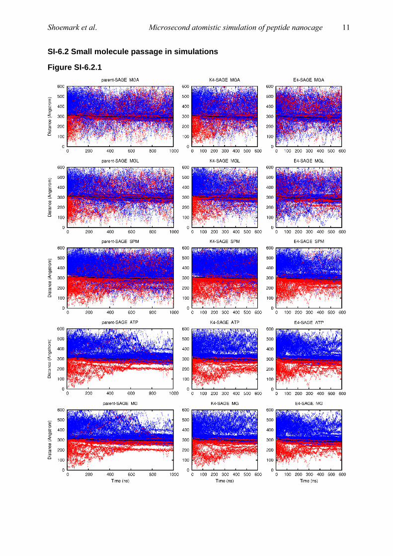
SI-6.2 Small molecule passage in simulations
Figure SI-6.2.1

Shoemark et al. Microsecond atomistic simulation of peptide nanocage 12
Figure SI-6.2.1 shows the radial position (distance from the center of the SAGE) of each of the 250 molecules
of each small-molecule with time during the simulations. The black line is the average position of the SAGE skin. At time zero, all molecules inside the SAGE are colored red, and all outside are colored blue.

Shoemark et al. Microsecond atomistic simulation of peptide nanocage 13
SI-6.3 Heat-mapping protein solute contacts with SAGE
Figure SI-6.3.1
Figure SI-6.3.1 shows heat maps for each of the parent-SAGE residues contacting anywhere on each of the
protein solute molecules.

Shoemark et al. Microsecond atomistic simulation of peptide nanocage 14
Figure SI-6.3.2
Figure SI-6.3.2 shows heat maps for each of the K4-SAGE residues contacting anywhere on each of the protein
solute molecules.

Shoemark et al. Microsecond atomistic simulation of peptide nanocage 15
Figure SI-6.3.3
Figure SI-6.3.3 shows heat maps for each of the E4-SAGE residues contacting anywhere on each of the protein
solute molecules.
Shoemark et al. Microsecond atomistic simulation of peptide nanocage 16
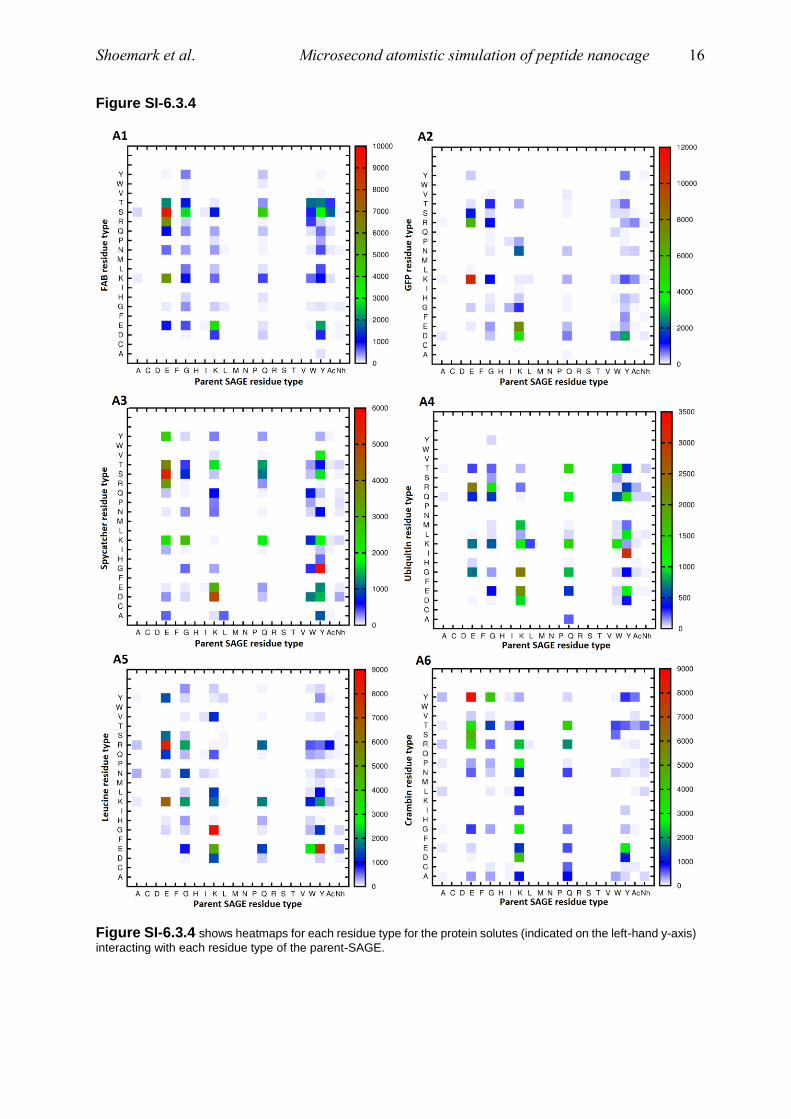
Figure SI-6.3.4
Figure SI-6.3.4 shows heatmaps for each residue type for the protein solutes (indicated on the left-hand y-axis)
interacting with each residue type of the parent-SAGE.

Shoemark et al. Microsecond atomistic simulation of peptide nanocage 17
Figure SI-6.3.5
Figure SI-6.3.5 shows heatmaps for each residue type for the protein solutes (indicated on the left-hand y-axis)
interacting with each residue type of the K4-SAGE.

Shoemark et al. Microsecond atomistic simulation of peptide nanocage 18
Figure SI-6.3.6
Figure SI-6.3.6 shows heatmaps for each residue type for the protein solutes (indicated on the left-hand y-axis) interacting with each residue type of the E4-SAGE.

Shoemark et al. Microsecond atomistic simulation of peptide nanocage 19
SI-6.4 Solute protein conformation and SAGE contact
SI-6.4.1 RMSDs of solute proteins in the context of their contact with parent-SAGE.
Figure SI-6.4.1 shows RMSDs of the individual solute protein chains in relation to their contact with parent-SAGE over the course of the trajectory.

Shoemark et al. Microsecond atomistic simulation of peptide nanocage 20
SI-6.4.2 RMSDs of solute proteins in the context of their contact with K4-SAGE.
Figure SI-6.4.2 shows RMSDs of the individual solute protein chains in relation to their contact with K4-SAGE over the course of the trajectory.
Shoemark et al. Microsecond atomistic simulation of peptide nanocage 21
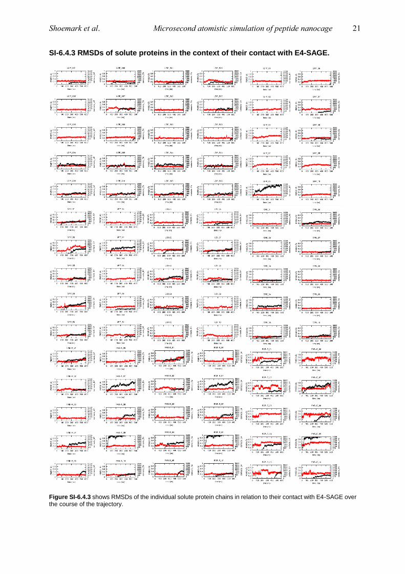
SI-6.4.3 RMSDs of solute proteins in the context of their contact with E4-SAGE.
Figure SI-6.4.3 shows RMSDs of the individual solute protein chains in relation to their contact with E4-SAGE over the course of the trajectory.

Shoemark et al. Microsecond atomistic simulation of peptide nanocage 22
Figure SI-6.4.4
Figure SI-6.4.4 represents the correlation between SAGE contacts and RMSD for the SAGE simulations. In panel A) Parent-SAGE, panel B) K4-SAGE and panel C) E4-SAGE, shows the extent to which SAGE contact contributed to conformational changes in solute proteins. There were 10 copies of each solute protein in all three simulations, so correlations (per chain) were averaged and shown here with standard deviation.
SI-7 Experimental observations of “stickiness” of the parent-SAGE
SI-7.1 SAGE binding experimental Methods
Synthesis of SAGE peptides: The HubA molecule for SAGE formation was produced as
described by Fletcher et al1. The HubB-K4 molecule for SAGE formation was produced as
described by Ross et al2. The HubB-E4 was produced as described by Galloway et al.3 Amino
acids were coupled using N,N’-diisopropylcarbodiimide and 6-chloro-1-hydroxybenzotriazole
in DMF, under microwave at 80 °C for 5 min. Fmoc deprotection occurred using 20% v:v
morpholine in DMF under microwave at 80°C for 5 min. After completion of automated
synthesis, the peptide was manually N-terminally acetylated via acetic anhydride (0.2 mmol)
and diisopropylethylamine (0.2 mmol) in DMF. Fmoc deprotection and resin cleavage
occurred in 2.5% v:v triisopropylsilane and 2.5% v:v water in trifluoroacetic acid (TFA) at 20
°C for 3 hours. The resin was removed by filtration and approximately half of the TFA was
evaporated under nitrogen flow. Crude peptide was precipitated with cold diethyl ether and
isolated by centrifugation. The pellet was dissolved in 50% v:v acetonitrile:water and
lyophilized. Peptides were purified with a semi-prep C18 reverse-phase column (Phenomenex
Kenetic, 5 µm, 100 Å, 10 mm x 150 mm) via HPLC (Jasco UK Ltd) under a linear acetonitrile
gradient with 0.1% TFA. Fractions were inspected by MALDI-TOF mass spectrometry followed
by analytical RP-HPLC (Phenomenex Kinetic, 5 µm, 100Å, 4.6 mm x 100 mm) and the desired
fractions were pooled and lyophilized.
SAGE formation and test for binding: 50 µM (one hub trimer peptide, covalently bound to one
dimeric peptide) stock solutions were prepared in 25 mM HEPES, 150 mM NaCl at pH 7.4.
SAGE particles were then assembled by mixing a 1:1 molar ratio of the two hubs and
incubating at room temperature for 1 hour. Assembled SAGE particles were then mixed 1:1 in
a volumetric ratio with a probe molecule and given a further 1 hour to bind to the SAGE
particles. The final concentration of SAGE peptides (as defined above) was kept constant at
25 µM and for an average sized, unilamellar SAGE there are approximately 1350 of these

Shoemark et al. Microsecond atomistic simulation of peptide nanocage 23
peptides. Samples were centrifuged for 6 min at 6000 x g, the supernatant was recovered and
the remaining concentration of the analyte was determined. Each of the experiments where
absorbance at 260 nm or 280 nm was used to determine concentrations was blanked against
a ‘SAGE only’ control set. Each of the experiments was also conducted in the absence of the
SAGE hub molecules, in triplicate, to provide a ‘non-SAGE’ control for comparison.
Measuring the sfGFP probe by fluorescence: sfGFP was prepared at 8 µM in 25 mM HEPES
pH 7.4, 150 mM NaCl and used in a 50 µl, final volume, SAGE binding assays in triplicate (as
described above). 30 µl of the supernatant was recovered and added to 70 µl of buffer A,
before the fluorescence was measured using a Spectrofluorometer (Jasco, FP-6500).
Concentrations were determined by comparison to a standard curve of sfGFP and adjusted to
account for the dilution of the supernatant.
SI-7.2 Experimental GFP binding to SAGE assemblies
Figure SI-7.2.1
Figure SI-7.1. Experiment to quantify the amount of sGFP adhering to the surface of the parent, E4 and K4 -
SAGEs in vitro using spectrophotometric means.
References:
1. Fletcher, J. M.; Harniman, R. L.; Barnes, F. R.; Boyle, A. L.; Collins, A.; Mantell, J.; Sharp, T. H.; Antognozzi, M.; Booth, P. J.; Linden, N.; Miles, M. J.; Sessions, R. B.; Verkade, P.; Woolfson, D. N., Self-assembling cages from coiled-coil peptide modules. Science 2013, 340 (6132), 595-9.DOI: 10.1021/ja2082476
2. Ross, J.F., Bridges, A., Fletcher, J.M., Shoemark D.K., Alibhai D., Bray H.E.V., Beesley, J. L.., Dawson, W.M., Hodgson, L.R., Mantell, J.; Verkade, P., Edge, C. M., Sessions, R.B., Tew D and Woolfson, D.N. Decorating Self-Assembled Peptide Cages with Proteins. ACS Nano 2017, 11, 7901−7914

Shoemark et al. Microsecond atomistic simulation of peptide nanocage 24
3. Galloway, J.M., Senior, L., Fletcher, J.M., Beesley, J.L., Hodgson, L.R., Harniman, R.L., Mantell, J.M., Coombs, J., Rhys, G.G., Xue, W.F., Mosayebi, M., Linden, N., Liverpool, T.B., Curnow, P., Verkade, P and Woolfson, D.N. Bioinspired Silicification Reveals Structural Detail in Self-Assembled Peptide Cages ACS Nano 2018, 12, 1420−1432
4. Hess, B., Kutzner, C., van der Spoel, D., Lindahl, E, GROMACS 4: Algorithms for Highly Efficient, Load-Balanced, and Scalable Molecular Simulation. J. Chem. Theory Comp 2008, 4 (3), 435–447.
5. Lindorff-Larsen, K., Piana, S., Palmo, K., Maragakis, P., Klepeis J.L., Dror R.O. and Shaw D.E. Improved side-chain torsion potentials for theAmber ff99SB protein force field. Proteins 2010, 78, 1950–1958.
6. Berendsen, H.J.C., Postma, J.P.M., van Gunsteren, W.F., DiNola, A., Haak, J.R. Molecular dynamics with coupling to an external bath. J. Chem. Phys., 1984 81(8):3684-90.
7. Miyamoto, S., Kollman, P.A. Settle: An analytical version of the SHAKE and RATTLE algorithm for rigid water models 1992 J. Comp. Chem 13 (8) 952-62
8. Hess, B., Bekker, H., Berendsen, H.J.C., Fraaije, J.G.E.M. LINCS: A Linear Constraint Solver for Molecular Simulations. 1997 J. Comp. Chem 18 (12) 1463-1472