Embed Size (px)
Citation preview


Shop Manual2001
DS 650

Legal deposit:National Library of Quebec3rd trimester 2000National Library of Canada 2000All rights reserved. No parts of this manual may be reproduced in anyform without the prior written permission of Bombardier Inc.©Bombardier Inc. 2000
Technical Publications Bombardier Inc.Valcourt (Quebec) Canada
Printed in Canada®*Registered trademarks of Bombardier Inc. and/or its subsidiaries.
This document contains the trademarks of the following companies:Kimtowels® is a trademark of Kimberly-ClarkLoctite® is a trademark of Loctite CorporationMolykote® is a trademark of Dow Corning CorporationSnap-on® is a trademark of Snap-on Tools Corporation

VMR2001_001_00_02A.FM I
SECTION SUBSECTION PAGE
SAFETY NOTICE................................................................................................................................... III
WHAT’S NEW ....................................................................................................................................... IV
INTRODUCTION .................................................................................................................................. V
01 SERVICE TOOLS AND SERVICE PRODUCTS
01 – Table of contents...................................................................... 01-01-102 – Service tools............................................................................. 01-02-103 – Service products....................................................................... 01-03-1
02 MAINTENANCE 01 – Table of contents...................................................................... 02-01-102 – Maintenance chart.................................................................... 02-02-103 – Maintenance/lubrication ........................................................... 02-03-104 – Storage/pre-season preparation ............................................... 02-04-1
03 ENGINE 01 – Table of contents...................................................................... 03-01-102 – Removal and installation........................................................... 03-02-103 – Cooling system......................................................................... 03-03-104 – Magneto system ...................................................................... 03-04-105 – Cylinder and head..................................................................... 03-05-106 – Crankshaft/balancer shaft......................................................... 03-06-107 – Lubrication system................................................................... 03-07-108 – Clutch ....................................................................................... 03-08-109 – Transmission ............................................................................ 03-09-1
04 FUEL SYSTEM 01 – Table of contents...................................................................... 04-01-102 – Fuel circuit ................................................................................ 04-02-103 – Carburetor and air intake silencer............................................. 04-03-1
05 ELECTRICAL 01 – Table of contents...................................................................... 05-01-102 – Overview.................................................................................. 05-02-103 – Charging system ...................................................................... 05-03-104 – Starting system ........................................................................ 05-04-105 – Ignition system......................................................................... 05-05-106 – Accessories .............................................................................. 05-06-1
06 DRIVE TRAIN 01 – Table of contents...................................................................... 06-01-102 – Front drive ................................................................................ 06-02-103 – Final drive ................................................................................. 06-03-1
07 STEERING/CONTROL SYSTEMS
01 – Table of contents...................................................................... 07-01-102 – Steering/control systems ......................................................... 07-02-1
08 SUSPENSION 01 – Table of contents...................................................................... 08-01-102 – Front suspension...................................................................... 08-02-103 – Rear suspension....................................................................... 08-03-1
09 BRAKES 01 – Table of contents...................................................................... 09-01-102 – Hydraulic brakes ....................................................................... 09-02-1
10 BODY/FRAME 01 – Table of contents...................................................................... 10-01-102 – Body ......................................................................................... 10-02-103 – Frame ....................................................................................... 10-03-1
TABLE OF CONTENTS

II VMR2001_001_00_02A.FM
11 TECHNICAL DATA 01 – SI metric information guide...................................................... 11-01-102 – Engine and vehicle ................................................................... 11-02-1
12 WIRING DIAGRAM 01 – Wiring diagram......................................................................... 12-01-1
SECTION SUBSECTION PAGE
TABLE OF CONTENTS

VMR2001_001_00_02A.FM III
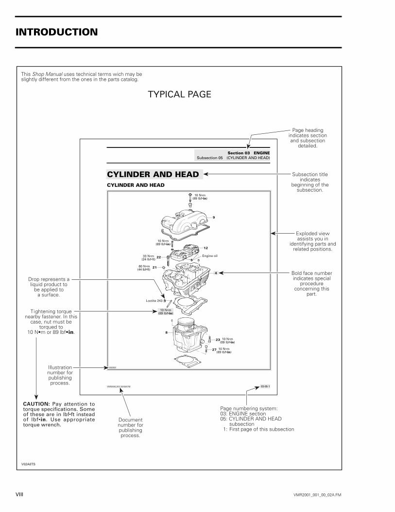
SAFETY NOTICE 0This manual has been prepared as a guide to correctly service and repair 2001 ATV.This edition was primarily published to be used by ATV mechanic technicians who are already familiarwith all service procedures relating to Bombardier made vehicles. Mechanic technicians should intent tocontinuous training courses given by Bombardier Training Department.Please note that the instructions will apply only if proper hand tools and special service tools are used.This shop manual uses technical terms which may be slightly different from the ones used in parts catalog.It is understood that this manual may be translated into another language. In the event of any discrepancy,the english version shall prevail.The content depicts parts and/or procedures applicable to the particular product at its time of writing.Service and Warranty Bulletins may be published to update the content of this manual. Make sure to readand understand these. It does not include dealer modifications, whether authorized or not by Bombardier,after manufacturing the product.In addition, the sole purpose of the illustrations throughout the manual, is to assist identification of thegeneral configuration of the parts. They are not to be interpreted as technical drawings or exact replicasof the parts.The use of Bombardier parts is most strongly recommended when considering replacement of any com-ponent. Dealer and/or distributor assistance should be sought in case of doubt.The engines and the corresponding components identified in this document should not be utilized onproduct(s) other than those mentioned in this document.Torque wrench tightening specifications must be strictly adhered to. Locking devices (ex.: locking tab,elastic stop nut, self-locking fasteners, etc.) must be installed or replaced with new ones, where specified.If the efficiency of a locking device is impaired, it must be renewed.This manual emphasizes particular information denoted by the wording and symbols:
CAUTION: Denotes an instruction which, if not followed, could severely damage vehicle compo-nents.NOTE: Indicates supplementary information needed to fully complete an instruction.Although the mere reading of such information does not eliminate the hazard, your understanding of theinformation will promote its correct use. Always use common shop safety practice.However, Bombardier disclaims liability for all damages and/or injuries resulting from the improper useof the contents. We strongly recommend that any services be carried out and/or verified by a highly skilledprofessional mechanic. It is understood that certain modifications may render use of the vehicle illegalunder existing federal, provincial and state regulations.
� WARNING
Identifies an instruction which, if not followed, could cause serious personal injury includingpossibility of death.
SAFETY NOTICE

IV VMR2001_001_00_02A.FM
WHAT’S NEW 0THIS SECTION INDICATES PROCEDURES THAT WERE MODIFIED OR NEWLY ADDED IN THIS MANUAL.
INTRODUCTION• Self-locking fasteners procedure.• Loctite application procedure.
SERVICE TOOLS AND PRODUCTS Added the following new tools:
• ball joint guide• ball joint driver.
Added the following new products:• premix coolant• Molykote 111 paste• Molykote G-n paste• sealing compound Dreibond.
MAINTENANCE • New clutch adjustment procedure.• Drive chain adjustment procedure is now in the MAINTENANCE section.
COOLING SYSTEM• New refilling procedure.
CRANKSHAFT/BALANCER SHAFT• New procedure to recentre crankshaft and balancer shaft.
REAR SUSPENSION• Rear suspension adjustment is added in the section.
TECHNICAL DATA• New starter jet.• New torque for rear shock bolts.
WHAT’S NEW

VMR2001_001_00_02A.FM V
INTRODUCTION 0This Shop Manual covers the following Bombar-dier made 2001 ATV:
Model
1. Model number
VEHICLE AND ENGINE SERIAL NUMBER LOCATION
1. Vehicle2. Engine
DS* 650 ..................................................... 7449
*Trademark of Bombardier Inc.
�
�������
�
�
�������
INTRODUCTION

VI VMR2001_001_00_02A.FM
Serial Number Meaning
�� �� �� �� �� �� �� ������������ ��� ��� ��� ��� ��� ��� ���
������ ���
��������������������
������� ���
������ �����!"���� #�����!"���� #������$�����"��� #�����$�"%�
��� ���
&����$"!"�
�� �� �� �� �� �� �� ����� ���
��'(�����)����"��� ����"!��$�( ��&��'�����������"���&��#��$���"���#������
���������'������������$��� ���
�������
INTRODUCTION

VMR2001_001_00_02A.FM VII
ARRANGEMENT OF THE MANUALThe manual is divided into 12 major sections:
Each section is divided in various subsections, andagain, each subsection has one or more division.
LIST OF ABBREVIATIONS USED IN THIS MANUAL
01 SERVICE TOOLS AND SERVICE PRODUCTS02 MAINTENANCE03 ENGINE04 FUEL SYSTEM05 ELECTRICAL06 DRIVE TRAIN07 STEERING/CONTROL SYSTEMS08 SUSPENSION09 BRAKES10 BODY/FRAME11 TECHNICAL DATA12 WIRING DIAGRAM
A ampere
amp ampere
A•h ampere-hour
AC alternate current
BDC bottom dead center
BTDC before top dead center
°C degree Celsius
cm centimeter
cm² square centimeter
cm³ cubic centimeter
DC direct current
°F degree Fahrenheit
fl. oz fluid ounce
ft foot
GRD ground
hal. halogen
I.D. inside diameter
IDI induction discharge ignition
imp. oz imperial ounce
in inch
in² square inch
in³ cubic inch
k kilo (thousand)
kg kilogram
km/h kilometer per hour
kPa kilo pascal
L liter
lb pound
lbf pound (force)
lbf/in² pound per square inch
LH left hand
m meter
MAG magneto
Max. maximum
Min. minimum
mL milliliter
mm millimeter
MPEM multi-purpose electronic module
MPH mile per hour
N newton
N.A. not applicable
no. number
00.0 continuity
0.L overload (open circuit)
O.D. outside diameter
OPT optional
oz ounce
P/N part number
PSI pound per square inch
PTO power take off
RPM revolution per minute
Sp. Gr. specific gravity
TDC top dead center
U.S. oz ounce (United States)
V volt
Vac volt (alternative current)
INTRODUCTION
VIII VMR2001_001_00_02A.FM
�������� �� �����(����"����* +,-��./���.�0�.1
����������������� � ��2�*2�
����������������������������������
�
��
�
�
��
��
�
��
�����
����3'+45��(�3��1
����3'+45��(�3��1
����3'+����(�3��1
����3'+45��(�3��1
-���"������
����3'+45��(�3��1
����3'+45��(�3��1
6���3'+����(�3��1
�!"����"�
����������������������������������������������������
������������ ��!�����������"�����"!�����!�
�����!���������"�!��
#������������!$�����!�%��������!��&����������'����� ��������!$������
(��)* ��!�+,����*���
#�������������������������������! ��-���� �%����������%������!�����!� �����������������"�!�����������
./"������0��-��������%�����
�������%����"�!������!�������"���������
�,���-���7
�������
&�����!������� ��!���!"���������"!������
1������������������������
���������������������������
2!�"�!�"!����������$����"!������������""�����������!�����
������� ��!�����%��� 3��3�.)4&).���������3�567&)2.���)2�8.�2� ������������(3 �!���"����������������������
�� �������� �������"��� �����)����#��"�"���"���8���'�����&��������"���(�3���"�����$��� �(�3��8� 9��� �##��#�"������)���:����&8
2��� ����� ��!���!"���������"!������
INTRODUCTION

VMR2001_001_00_02A.FM IX
�,���-���7
1����������������� ����"!�����!���������!!�������
����!�����������9�"�����!���������������������������&�������������������!��
��!��!���!�������!����9���������!�
������������ ��!�����-����"�!���� �!���!������/"�����0��-����������������
�����������
5����������!���0��������!������
�����9�
�
����4� * � � �
����5�
�����*�
���2���
�������� �� �����(����"����� +/� ��-���.������--��� �1
����������:������� � ��2��2�
; ����!����<!���!�����=26>; �������"����� ��8 � <!���!��� �!"����"�"�� �������>
/0���.� � �7��(� ./������"�"���� �������!������ ������ =�������:� �!�9��"����� ���!���
; ��!��!���!�������!��!���!����"��!�<!���!����5���?�.#=���)2��&��&)#�@.�1&7.)5.�>
; ���!������"���� ��8 5�?���!�-�����!����-�������������!�
/�'�%���� �0�������""�! ��""�!���!��9�� ��8 ����� "�����%�
&���������������������������<�A)��,��� B(�>�����'����������������
�� �0�3; �""�!����������""�!������ ��8 ��; ��-�!������ ��8 �� !������������������� ��""�!���8 �� ��������!�����'�����'�!� �0����""�!��
; �!������-�!� ������������ ��8 ��; !��!���-�!� ������������ ��8 �*; !��!��""�!� ������������ ��8 �6��� �0����������!� �0�������
���������"�� �!� ������������' !�0�!�� ���� !� �0��� "!�����!�'"�%��������������������������-���������������������������'������'�-�!������!����'�������C��� �������������������!��!��!�9������!��������!������������'�!� �0�����������!�?��������"!����!� �����������!�-�
;0��.� �-���-�/(� �����������!�-
?���!�-�����!� �0�������"�!9 "����#�!������������������!��!������������ �!������������!��� ��!�#�������"!����!� �����������!�-�&����������������!�#�����"�!����������0�������������"� "��5���9��� 0������ !������!!����%�
�
����4� * � � �
����5�
�����*�
���2���
INTRODUCTION
X VMR2001_001_00_02A.FM
GENERAL INFORMATIONThe information and component/system descrip-tions contained in this manual are correct at timeof publication. Bombardier however, maintains apolicy of continuous improvement of its productswithout imposing upon itself any obligation to in-stall them on products previously manufactured.Due to late changes, it may have some differencesbetween the manufactured product and the descrip-tion and/or specifications in this document.Bombardier reserves the right at any time to dis-continue or change specifications, designs, fea-tures, models or equipment without incurring ob-ligation.
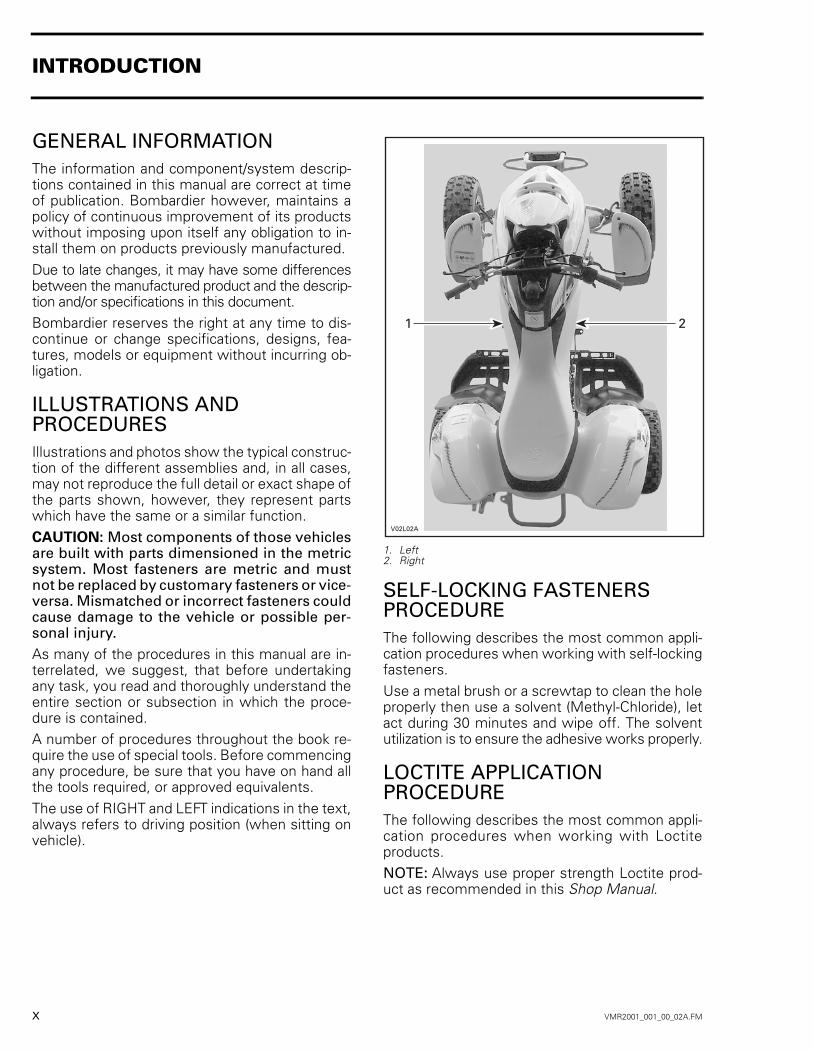
ILLUSTRATIONS AND PROCEDURESIllustrations and photos show the typical construc-tion of the different assemblies and, in all cases,may not reproduce the full detail or exact shape ofthe parts shown, however, they represent partswhich have the same or a similar function.CAUTION: Most components of those vehiclesare built with parts dimensioned in the metricsystem. Most fasteners are metric and mustnot be replaced by customary fasteners or vice-versa. Mismatched or incorrect fasteners couldcause damage to the vehicle or possible per-sonal injury.As many of the procedures in this manual are in-terrelated, we suggest, that before undertakingany task, you read and thoroughly understand theentire section or subsection in which the proce-dure is contained.A number of procedures throughout the book re-quire the use of special tools. Before commencingany procedure, be sure that you have on hand allthe tools required, or approved equivalents.The use of RIGHT and LEFT indications in the text,always refers to driving position (when sitting onvehicle).
1. Left2. Right
SELF-LOCKING FASTENERS PROCEDUREThe following describes the most common appli-cation procedures when working with self-lockingfasteners.Use a metal brush or a screwtap to clean the holeproperly then use a solvent (Methyl-Chloride), letact during 30 minutes and wipe off. The solventutilization is to ensure the adhesive works properly.
LOCTITE APPLICATION PROCEDUREThe following describes the most common appli-cation procedures when working with Loctiteproducts.NOTE: Always use proper strength Loctite prod-uct as recommended in this Shop Manual.
���-���
��
INTRODUCTION

VMR2001_001_00_02A.FM XI
Threadlocker Uncovered Holes (bolts and nuts)
1. Apply here2. Do not apply
1. Clean threads (bolt and nut) with solvent.2. Apply Loctite Primer N (P/N 293 800 041) on
threads and allow to dry.3. Choose proper strength Loctite threadlocker.4. Fit bolt in the hole.5. Apply a few drops of threadlocker at proposed
tightened nut engagement area.6. Position nut and tighten as required.
Blind Holes
1. On threads2. On threads and at the bottom of hole
1. Clean threads (bolt and hole) with solvent.2. Apply Loctite Primer N (P/N 293 800 041) on
threads (bolt and nut) and allow to dry for 30seconds.
3. Choose proper strength Loctite threadlocker.4. Apply several drops along the threaded hole and
at the bottom of the hole.5. Apply several drops on bolt threads.6. Tighten as required.
Stud in Blind Holes
1. On threads2. On threads and in the hole3. Onto nut threads
1. Clean threads (stud and hole) with solvent.2. Apply Loctite Primer N (P/N 293 800 041) on
threads and allow to dry.3. Put several drops of proper strength Loctite
threadlocker on female threads and in hole.4. Apply several drops of proper strength Loctite
on stud threads.5. Install stud.6. Install cover, etc.7. Apply drops of proper strength Loctite on un-
covered threads.8. Tighten nuts as required.
A00A3LA
1
2
�������
�
�
����*/�
�
� �
INTRODUCTION

XII VMR2001_001_00_02A.FM
Preassembled Parts
1. Apply here2. Do not apply
1. Clean bolts and nuts with solvent.2. Assemble components.3. Tighten nuts.4. Apply drops of proper strength Loctite on bolt/nut
contact surfaces.5. Avoid touching metal with tip of flask.NOTE: For preventive maintenance on existingequipment, retighten nuts and apply properstrength Loctite on bolt/nut contact surfaces.
Adjusting Screw
1. Apply here2. Plunger
1. Adjust screw to proper setting.2. Apply drops of proper strength Loctite thread-
locker on screw/body contact surfaces.3. Avoid touching metal with tip of flask.
NOTE: If it is difficult to readjust, heat screw witha soldering iron (232°C (450°F)).
Stripped Thread RepairStripped Threads
1. Release agent2. Stripped threads3. Form-A-Thread4. Tape5. Cleaned bolt6. Plate7. New threads8. Threadlocker
Standard Thread Repair1. Follow instructions on Loctite FORM-A-THREAD
(P/N 413 708 600) package.2. If a plate is used to align bolt:
a. Apply release agent on mating surfaces.b. Put waxed paper or similar film on the surfaces.
3. Twist bolt when inserting it to improve threadconformation.
NOTE: NOT intended for engine stud repairs.
Repair of Small Holes/Fine ThreadsOption 1: Enlarge damaged hole, then followStandard Thread Repair procedure.Option 2: Apply FORM-A-THREAD on the screwand insert in damaged hole.
Permanent Stud Installation (light duty)1. Use a stud or thread on desired length.2. DO NOT apply release agent on stud.3. Do a Standard Thread Repair.4. Allow to cure for 30 minutes.5. Assemble.
A00A3OA
1
2
�������
��
�������
*
46
<
�
�
�
�
INTRODUCTION
VMR2001_001_00_02A.FM XIII
Mounting on ShaftMounting with a Press
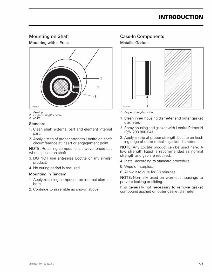
1. Bearing2. Proper strength Loctite3. Shaft
Standard1. Clean shaft external part and element internal
part.2. Apply a strip of proper strength Loctite on shaft
circumference at insert or engagement point.NOTE: Retaining compound is always forced outwhen applied on shaft.3. DO NOT use anti-seize Loctite or any similar
product.4. No curing period is required.
Mounting in Tandem1. Apply retaining compound on internal element
bore.2. Continue to assemble as shown above.
Case-In ComponentsMetallic Gaskets
1. Proper strength Loctite
1. Clean inner housing diameter and outer gasketdiameter.
2. Spray housing and gasket with Loctite Primer N(P/N 293 800 041).
3. Apply a strip of proper strength Loctite on lead-ing edge of outer metallic gasket diameter.
NOTE: Any Loctite product can be used here. Alow strength liquid is recommended as normalstrength and gap are required.4. Install according to standard procedure.5. Wipe off surplus.6. Allow it to cure for 30 minutes.NOTE: Normally used on worn-out housings toprevent leaking or sliding.It is generally not necessary to remove gasketcompound applied on outer gasket diameter.
A00A3UA
1
2
3
A00A3VA 1
INTRODUCTION

XIV VMR2001_001_00_02A.FM
TIGHTENING TORQUESTighten fasteners to torque mentioned in explod-ed views and text. When they are not specifiedrefer to following table.The table also gives themetric conversion.
N•M FASTENER SIZE (8.8) LBF•IN1 92 M4 183 274 M5 355 446 537 628 719 8010 M6 8911 9712 10613 11514 12415 13316 14217 15018 15919 168
N•M FASTENER SIZE (8.8) LBF•FT20 1521 1522 1623 M8 1724 1825 1826 1927 2028 2129 2130 2231 2332 2433 2434 2535 2636 2737 2738 2839 2940 3041 3042 3143 3244 3245 3346 3447 3548 M10 3549 3650 3751 3852 3853 3954 4055 4156 4157 4258 4359 4460 4461 4562 4663 4664 47
INTRODUCTION

VMR2001_001_00_02A.FM XV
TIGHTENING TORQUES FOR 8.8 GRADE BOLTS AND NUTS
N•M FASTENER SIZE (8.8) LBF•FT65 4866 4967 4968 5069 5170 5271 5272 5373 5474 5575 5576 5677 5778 5879 5880 M12 5981 6082 6083 6184 6285 6386 6387 6488 6589 6690 6691 6792 6893 6994 6995 7096 7197 7298 7299 73
100 74101 74102 75103 76104 77105 77106 78107 79108 80
N•M FASTENER SIZE (8.8) LBF•FT109 80110 81111 82112 83113 83114 84115 85116 86117 86118 87119 88120 89121 89122 90123 91124 91125 92126 93127 94128 94129 95130 96131 97132 97133 98134 99135 M14 100136 100137 101138 102139 103140 103141 104142 105143 105144 106145 107146 108147 108148 109149 110150 111
INTRODUCTION
We would be pleased if you couldcommunicate to Bombardier any sug-gestions you may have concerningour publications.
✁
Bombardier SERVICE PUBLICATIONS REPORTPublication title and year ________________________ Page______Machine___________________ Report of error ❏ Suggestion ❏________________________________________________________________________________________________________________________________________________________________________________________________________________________________________________________________________________________________________________________________________________________________________
Name ______________________________________________________Address ____________________________________________________City and State/Prov. ________________________ Date___________Zip code/Postal code ________________________________________

AFFIX
PROPER
POSTAGE
AFFIX
PROPER
POSTAGE
AFFIX
PROPER
POSTAGE
Technical PublicationsAfter Sales Service565 de la Montagne StreetValcourt, Québec, Canada J0E 2L0
Technical PublicationsAfter Sales Service565 de la Montagne StreetValcourt, Québec, Canada J0E 2L0
Technical PublicationsAfter Sales Service565 de la Montagne StreetValcourt, Québec, Canada J0E 2L0