Embed Size (px)
Citation preview

www.omega.com e-mail: [email protected]
User’s Guide
WT4401-S & WT4401-DBenchtop Wind Tunnels
Shop online at
WT4401-D shown

Servicing North America:USA: One Omega Drive, P.O. Box 4047ISO 9001 Certified Stamford CT 06907-0047
TEL: (203) 359-1660 FAX: (203) 359-7700e-mail: [email protected]
Canada: 976 BergarLaval (Quebec) H7L 5A1TEL: (514) 856-6928 FAX: (514) 856-6886e-mail: [email protected]
For immediate technical or application assistance:USA and Canada: Sales Service: 1-800-826-6342 / 1-800-TC-OMEGA®
Customer Service: 1-800-622-2378 / 1-800-622-BEST®
Engineering Service: 1-800-872-9436 / 1-800-USA-WHEN®
TELEX: 996404 EASYLINK: 62968934 CABLE: OMEGA
Mexico: En Espanol: (001) 203-359-7803 e-mail: [email protected]: (001) 203-359-7807 [email protected]
Servicing Europe:Benelux: Postbus 8034, 1180 LA Amstelveen, The Netherlands
TEL: +31 (0)20 3472121 FAX: +31 (0)20 6434643Toll Free in Benelux: 0800 0993344e-mail: [email protected]
Czech Republic: Frystatska 184, 733 01 Karviná 8, Czech RepublicTEL: +420 (0)59 6311899 FAX: +420 (0)59 6311114Toll Free: 0800-1-66342 e-mail: [email protected]
France: 11, rue Jacques Cartier, 78280 Guyancourt, FranceTEL: +33 (0)1 61 37 29 00 FAX: +33 (0)1 30 57 54 27Toll Free in France: 0800 466 342e-mail: [email protected]
Germany/Austria: Daimlerstrasse 26, D-75392 Deckenpfronn, GermanyTEL: +49 (0)7056 9398-0 FAX: +49 (0)7056 9398-29Toll Free in Germany: 0800 639 7678e-mail: [email protected]
United Kingdom: One Omega Drive, River Bend Technology CentreISO 9002 Certified Northbank, Irlam, Manchester
M44 5BD United Kingdom TEL: +44 (0)161 777 6611 FAX: +44 (0)161 777 6622Toll Free in United Kingdom: 0800-488-488e-mail: [email protected]
OMEGAnet® Online Service Internet e-mailwww.omega.com [email protected]
It is the policy of OMEGA to comply with all worldwide safety and EMC/EMI regulations thatapply. OMEGA is constantly pursuing certification of its products to the European New ApproachDirectives. OMEGA will add the CE mark to every appropriate device upon certification.The information contained in this document is believed to be correct, but OMEGA Engineering, Inc. accepts no liability for any errors it contains, and reserves the right to alter specifications without notice.WARNING: These products are not designed for use in, and should not be used for, patient-connected applications.

Wind Tunnel
i
TABLE OFCONTENTS
Page
Chapter 1 Introduction .......................................................................... 11.1 Description ....................................................................................................... 11.2 Unpacking ........................................................................................................ 2
Chapter 2 Setting Up the Wind Tunnel ................................................... 52.1 Precautions ........................................................................................................ 52.2 Setup Procedure ............................................................................................... 5
Chapter 3 Installing the Wind Tunnel ..................................................... 9
Chapter 4 Operating Instructions ........................................................ 11
Chapter 5 Calibrating at other Flow Rates Not Listed in the Calibration Sheets ..................................................... 13
Chapter 6 Specifications ...................................................................... 15
Chapter 7 In Case of Problems ............................................................ 17
Chapter 8 Maintenance ....................................................................... 19
Chapter 9 Spare Parts and Replacement Parts .................................... 21
Appendix A Differential Pressure Fluctuation Errors ............................ 23
Appendix B Barometric Pressure Calculations ..................................... 25

Wind Tunnel
ii
TABLE OFCONTENTS
Introduction
1
1
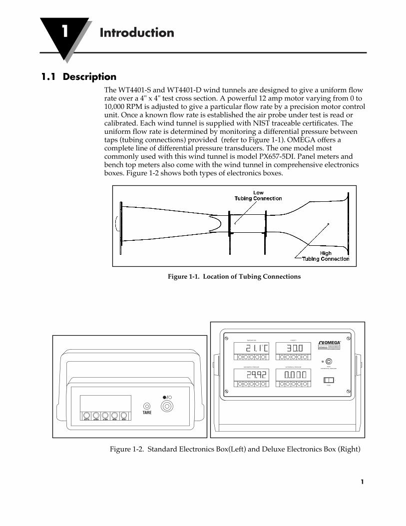
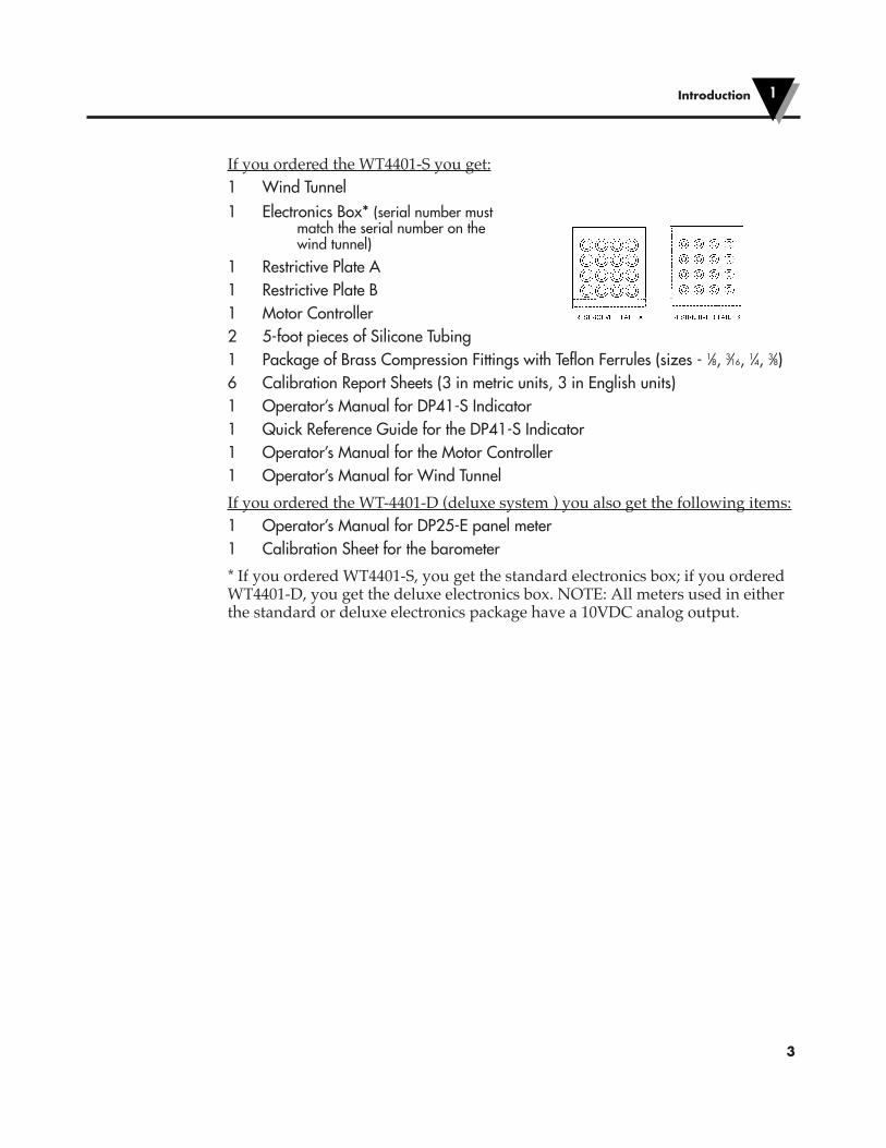
1.1 DescriptionThe WT4401-S and WT4401-D wind tunnels are designed to give a uniform flowrate over a 4" x 4" test cross section. A powerful 12 amp motor varying from 0 to 10,000 RPM is adjusted to give a particular flow rate by a precision motor controlunit. Once a known flow rate is established the air probe under test is read orcalibrated. Each wind tunnel is supplied with NIST traceable certificates. Theuniform flow rate is determined by monitoring a differential pressure betweentaps (tubing connections) provided (refer to Figure 1-1). OMEGA offers acomplete line of differential pressure transducers. The one model mostcommonly used with this wind tunnel is model PX657-5DI. Panel meters andbench top meters also come with the wind tunnel in comprehensive electronicsboxes. Figure 1-2 shows both types of electronics boxes.
Figure 1-1. Location of Tubing Connections
Figure 1-2. Standard Electronics Box(Left) and Deluxe Electronics Box (Right)
DIFFERENTIAL PRESSUREBAROMETRIC PRESSURE
HUMIDITY
DIFFERENTIAL PRESSURE
POWE
ZERO
I
WT4401-D
TEMPERATURE
TARESETPTS ▲/MAX /MIN
▲
MENU RESET
/

A differential pressure measurement used to establish known flow rates isaffected by barometric pressure, and temperature conditions during testing.Depending on the probe being calibrated, humidity might also be a factor.OMEGA offers a complete system to monitor differential pressure, ambientbarometric pressure, ambient temperature, and ambient humidity conditions.Each wind tunnel is supplied with two restrictive plates for achieving optimumlower flow rates. The established differential pressure measurements versus flowrates are listed from 25 to 9000 FPM. Calibration sheets are included to makecalibrating different flow sensors simple. An assortment of compression fittingsis provided to help mount your probe under calibration.
This system features:• Compact design to take up “little bench-top space”• Precise motor control for adjusting flow rates• NIST calibration sheets supplied with each wind tunnel• Highly accurate to 1% of reading• Large 4” x 4” test chamber• Highly stable delta pressure sensor and readout(s) included with each wind
tunnel• Optional environmental monitoring package of temperature, humidity,
barometric pressure and delta pressure available.
1.2 UnpackingRemove the Packing List and verify that you have received all equipment. If youhave any questions about the shipment, please call the OMEGA CustomerService Department at 1-800-622-2378 or (203) 359-1660.
When you receive the shipment, inspect the container and equipment for anysigns of damage. Note any evidence of rough handling in transit. Immediatelyreport any damage to the shipping agent.
The carrier will not honor any claims unless all shippingmaterial is saved for their examination. After examining andremoving contents, save packing material and carton in theevent reshipment is necessary.
NOTE
Introduction1
2
3
If you ordered the WT4401-S you get:1 Wind Tunnel1 Electronics Box* (serial number must
match the serial number on thewind tunnel)
1 Restrictive Plate A1 Restrictive Plate B1 Motor Controller2 5-foot pieces of Silicone Tubing1 Package of Brass Compression Fittings with Teflon Ferrules (sizes - 1⁄8, 3⁄16, 1⁄4, 3⁄8)6 Calibration Report Sheets (3 in metric units, 3 in English units)1 Operator’s Manual for DP41-S Indicator 1 Quick Reference Guide for the DP41-S Indicator1 Operator’s Manual for the Motor Controller1 Operator’s Manual for Wind Tunnel
If you ordered the WT-4401-D (deluxe system ) you also get the following items:1 Operator’s Manual for DP25-E panel meter1 Calibration Sheet for the barometer
* If you ordered WT4401-S, you get the standard electronics box; if you orderedWT4401-D, you get the deluxe electronics box. NOTE: All meters used in eitherthe standard or deluxe electronics package have a 10VDC analog output.
Introduction 1

Introduction1
4
Notes

2.1 PrecautionsA wind tunnel’s performance can be severely diminished if not used with thefollowing considerations in mind.
• Do not use the wind tunnel in small rooms with less than 1,800 cubic feet.The air flow creates currents that undermine the wind tunnel’s accuracy.
• Avoid locating the intake and exhaust toward open windows, doorways orcorridors where people are walking. The effect of air current changes acrossthe intake has a severe affect on the flow rate changing in the wind tunnel.
• Locate the exhaust towards the largest open area of the room to minimizeroom air currents. Naturally the higher the flow rate, the more chance ofcreating currents exists.
2.2 Setup ProcedureRefer to Table 2-1 for flow ranges.
Table 2-1Flow Ranges
WIND TUNNEL CONFIGURATION FLOW RANGES ACCURACY
No restrictive plate used 1000 to 7500 fpm 1% reading
Restrictive Plate A used 250 to 1500 fpm 2% reading
Restrictive Plate B used 25 to 300 fpm 2% reading
After determining which flow range you wish to calibrate at, and whether youneed a restrictive plate, go through the following procedure to install it orremove it.
1. Remove two thumbscrews and remove the small plexiglass cover.
2. Inspect the gasket around the four sides of restrictive plate first. The gasketshould provide a good seal when the plate is inserted into the slots. If not,replace it. It would be a good idea to have extra gaskets on hand.
3. Slide restrictive plate into the slots in the center of the wind tunnel. Keep the flatside upstream. Refer to Figure 2-1 for the proper orientation of the restrictiveplate. Or remove the plate if you don’t need it.
4. Replace plexiglass cover and screws.
Figure 2-2 shows the direction of air flow through one type of restrictive plate.
Chapter 3 describes how to set up the whole Wind Tunnel including theElectronics Instrument Box both of which are shown in Figures 2-3 and 2-4.
Setting Up the Wind Tunnel
5
2

Setting Up the Wind Tunnel2
6
Figure 2-1. Restrictive Plate Placement
Figure 2-2. Air Flow

7
Figure 2-3. Standard Electronics BoxTOP (front); BOTTOM (Rear)
The TARE button on the front of the electronics box is used to zero out the meter.The ON/OFF power button is to its right.
The REC connector is used to hook up any device with 10VDC analog output. Asshown in the bottom figure, the power cord receptacle is rated for a 115VACpower cord.
DIFFERENTIAL PRESSUREBAROMETRIC PRESSURE
HUMIDITY
DIFFERENTIAL PRESSURE
POWE
ZERO
I
WT4401-D
TEMPERATURE
MADE IN THE U.S.A.
POWER FROM SOURCE BEFORE CHANGING FUSE.
TYPE, RATING AND SIZE OF FUSE. DISCONNECT
THE RISK OF FIRE REPLACE WITH ONLY THE SAME
CAUTION: FOR CONTINUED PROTECTION AGAINST
1-800-826-6342
STAMFORD, CT. 06907-0047
OMEGA ENGINEERING INC.
SERIAL NO:
MODEL NO:
www.omega.com
WT4401-D
POWER:
FUSE:
+
TEM
+ +- -
RH
-
BAR
-+
DP
HIGH LO
Setting Up the Wind Tunnel 2

2
8
Figure 2-4. Deluxe Electronics BoxTOP (Front); BOTTOM (Rear)
The TARE button on the front of the electronics box is used to zero out theDifferential Pressure meter only. The ON/OFF power button is below it.
The bottom terminal strip labeled TEMP/RH/BAR/DP is used to hook up anydevice with 10VDC analog output. As shown in the bottom figure, the powercord receptacle is rated for a 115VAC power cord.
HIGH LOW
115 VAC
+ –REC
TARESETPTS ▲/MAX /MIN
▲
MENU RESET
/
Setting Up the Wind Tunnel

Installing the Wind Tunnel
9
3
1. After unpacking the box, place the wind tunnel on a level table top. Refer toChapter 2 on how to select the correct size room and how to orient the windtunnel correctly in the room.
2. Set up the motor controller. To do this, examine that the ON/OFF switch on thecontroller box is in the OFF position and be certain that the potentiometer isfully counter-clockwise. Connect the two elongated connectors together to hookup the motor and plug the motor controller into a live 120VAC outlet. DO NOTTURN ON THE CONTROLLER.
3. Place the electronics box next to the tunnel. Attach the two (2) pieces of tubingas shown in Figures 3-1 and 3-2. Also attach the power cord to the rear of thebox. DO NOT TURN ON THE ELECTRONICS BOX YET EITHER.
Figure 3-1 (Left). Tubing Placement with Standard Electronics Box and Wind Tunnel
Figure 3-2 (Right). Tubing Placement with Deluxe Electronics Box and Wind Tunnel
HIGH
HIGH
LOW
LOW
MADE IN THE U.S.A.
POWER FROM SOURCE BEFORE CHANGING FUSE.TYPE, RATING AND SIZE OF FUSE. DISCONNECTTHE RISK OF FIRE REPLACE WITH ONLY THE SAMECAUTION: FOR CONTINUED PROTECTION AGAINST
1-800-826-6342STAMFORD, CT. 06907-0047OMEGA ENGINEERING INC.
SERIAL NO:
MODEL NO:
www.omega.com
WT4401-D
POWER:
FUSE:
TEMP RH BAR DP
HIGH LOW
115 VAC
+ –REC
HIGHLOW

Installing the Wind Tunnel
10
4. Using the compressing fittings provided, mount the probe to be calibrated in thewind tunnel. Refer to Figure 3-3. Some probes have directional air flow forupstream and downstream sides. Make sure the probe is installed without anyleaks.
5. Continue to Chapter 4, Operating Instructions.
Figure 3-3. Probe Placement
3

Operating Instructions
11
4
IMPORTANT - ALWAYS KEEP YOUR ORIGINAL CALIBRATION REPORTS INGOOD, CLEAN CONDITION FOR FUTURE COPYING. MAKE DUPLICATECOPIES OF THE CALIBRATION REPORTS YOU DESIRE.
The differential pressures recorded in column 2 are at lab conditions (∆Ps).Standard conditions are at 70°F (21.1°C) and 29.92 in Hg. Since your test will notbe at the same conditions you need to calculate what the actual differentialpressures (∆Pa) will be during your operating conditions. A correction factor forair density (K) needs to be determined. Differential pressures at standardconditions are listed in Appendix A.
1. Supplied with the wind tunnel are Calibration Report sheets. Your wind tunnelcan be used in different applications: with no Restrictive Plate, with RestrictivePlate A or with Restrictive Plate B. Each pair of sheets for each plate style isfurther broken down to two different units of measure - feet per minute andmeters per second. Examine the differences between the sheets and obtain theapplicable Calibration Report sheet for your application and photocopy it.
2. Fill in the ambient barometric pressure and ambient temperature in the spaceprovided on the Calibration Report. Using the “K” formula on the sheets and acalculator, figure out the K factor. Take each value in column 2 and multiply itby K and write the values in column 3.
Column 3 is the differential pressures that will correspond to the given flowrates in column 1. The values in column 3 will be used in the wind tunnel setup.The top part of a calibration report is shown on the next page. If you do not havea barometer, refer to Appendix B.
3. Turn on the electronics box. If you need to zero the display, press the TAREbutton (on the Deluxe Electronics Box the only display that is zeroed is theDifferential Pressure display).
4. Turn on the motor by flipping on the ON/OFF switch and turning thepotentiometer slowly clockwise and increase the motor speed until the actualdifferential pressure in column 3 is achieved.
At high speed, you will notice that the differential display tends to jump arounda little which makes it tough to get the exact same ∆ P as indicated in column 3.Refer to Appendix A for this effect.
5. Record the velocity from the air probe under calibration in column 4.
6. Continue increasing the flow rates until you have covered the complete rangeyou wish to calibrate.

SAMPLECALIBRATION REPORT
Report Number: Correction Factor: K= (29.92/P) X (460+T)/530 = _________
Serial Number: Where Tested Atmospheric Conditions:
Model Number: P= Barometric Pressure = _____________(in Hg)
Range: T= Atm Pressure = ___________________(F)
Date Calibrated:
Due Date:
NO RESTRICTIVE PLATES
STANDARD ACTUAL = Ps(K) UNIT UNDER TEST
VELOCITY (FPM) PS (mmHg) Pa( mmHg)column 1 column 2 column 3 column 4
Operating Instructions4
12

Calibrating at Other Flow Rates NotListed in the Calibration Sheets
13
5
To determine the ∆P that corresponds to the desired flow rate use the followingformula:
where: P1 is the delta P corresponding to velocity 1
P2 is the delta P corresponding to velocity 2
V1 is a known velocity from the Calibration tables
V2 is a desired velocity not listed in the Calibration tables
Sometimes a given delta P is observed and you would like to know what flowrate it corresponds to (use the following formula):
where: P1 is the known actual delta P from column 4 in tables
P2 is the measured ∆P
V1 is the velocity from the tables corresponding to ∆P1
V2 is the velocity that corresponds to ∆P2.
V2 = V1
P2
P1
P2 = P1
V2
V1
2

Calibrating at Other Flow Rates Not Listed in the Calibration Sheets5
14
Notes
Specifications
15
6
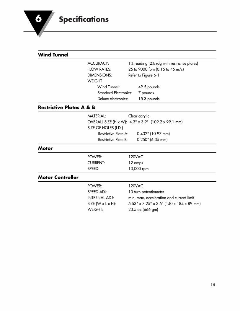
Wind Tunnel
ACCURACY: 1% reading (2% rdg with restrictive plates)FLOW RATES: 25 to 9000 fpm (0.15 to 45 m/s)DIMENSIONS: Refer to Figure 6-1WEIGHT
Wind Tunnel: 49.5 poundsStandard Electronics: 7 poundsDeluxe electronics: 15.3 pounds
Restrictive Plates A & B
MATERIAL: Clear acrylicOVERALL SIZE (H x W): 4.3" x 3.9" (109.2 x 99.1 mm)SIZE OF HOLES (I.D.)
Restrictive Plate A: 0.432" (10.97 mm)Restrictive Plate B: 0.250" (6.35 mm)
Motor
POWER: 120VACCURRENT: 12 ampsSPEED: 10,000 rpm
Motor Controller
POWER: 120VACSPEED ADJ: 10-turn potentiometerINTERNAL ADJ: min, max, acceleration and current limitSIZE (W x L x H): 5.53" x 7.25" x 3.5" (140 x 184 x 89 mm)WEIGHT: 23.5 oz (666 gm)

Figure 6-1. Dimensions
Specifications6
16

In Case of Problems
17
7
PROBLEM SOLUTION
?
?
?
Realign position of the fan
The wind tunnel is not on -no power to motor
Be sure the motor control-motor connector piecesare connected to each other.
Make sure the motor controller is plugged in andconnected to a live outlet.
Check the fuse in the motor controller - if blown,replace with same type and rating.
The wind tunnel is not on -fan does not turn.
Make sure the motor controller is plugged in andconnected to a live outlet.
Make sure the cabling from the motor controlleris connected to the motor.
Make sure the ON/OFF switch on the motorcontroller is “ON”.
If the switch on the motor controller is on, turnthe 10-turn potentiometer clockwise from the“OFF” position.
Make sure there are no obstructions in the fanarea of the wind tunnel.
Scraping noise from area of fan

In Case of Problems7
18
PROBLEM SOLUTION
?
?
?
?
?
Can’t get velocity desired. Check your AC power.
Check the position of the ON/OFF switch andpotentiometer on the motor controller.
Make sure the appropriate restrictive plate isused in the wind tunnel - see Chapter 2 for theappropriate style to use.
Make sure the gasket around the restrictive plateis in good condition. If not, replace the gasket.
Clean restrictive plate and black air filter ifnecessary. See Chapter 8 for details.
Poor repeatability.Examine all hoses for any leaks and replace any ifnecessary.
Locate the wind tunnel in room that has ATLEAST 1800 cubic feet of space.
Poor Accuracy. Determine if the pressure transducer is operatingcorrectly. If it is and there still is the accuracyproblem, return the wind tunnel to the factoryand get it recalibrated.
No readings from any of thereadouts
Check the operation of the individual meters.Consult the appropriate operator’s manualsprovided for details.
Incorrect readings from anyof the readouts.
Check the operation of the individual meters.Consult the appropriate operator’s manualsprovided for details.

Maintenance
19
8
The following points should be adhered to for a maintenance-free operation ofthe wind tunnel.
• Make sure the wind tunnel is operating in a relatively dirt-free room that isAT LEAST 1,800 cubic feet.
• If the restrictive plate(s) should get dirty for any reason, they can be cleanedvery easily using a mild soap or detergent.
Do not use any solvents.
• To clean the black filter, gently clean using mild soap or detergent. Let thefilter drip dry only.
• Make sure the silicone tubing is crimp-free and provides a good seal withthe compression fittings. Replace if necessary.
CAUTION

Maintenance8
20
Notes

21
DESCRIPTION PART NUMBER
Restrictive Plate Cover WT-0011
Restrictive Plate A WT-0012
Restrictive Plate B WT-0013
Restrictive Plate Gasket WT-0014
Honeycomb Flow Straightener WT-0022
Black Filter WT-0023
Thumb Screw for Restrictive Plate Cover (Ass’y) WT-0060
One Piece of 5-ft Silicone Tubing KCC-0132
Spare Parts and Replacement Parts9

Spare Parts and Replacement Parts9
22
Notes

23
Achieving the exact desired pressure measurement at high delta pressures issometimes a tough thing to do. The fluctuations, although appearing to be large,are actually quite small. The table on the next page shows the delta pressurecorresponding to a 1% change in air flow velocity.
The reason why a large change in differential pressure causes only a 1% changein the standard flow rate is because the flow rate is proportional to the squareroot of the ∆P. This square root relationship is shown as follows:
The percentage change in pressure corresponding to a 1% change in velocity is asfollows:
1 + 0.01( )2 = 1.0201( ) = 1 + ∆PP1
⇒ 2.01% = ∆PP1
V2 = V1
P2
P1
⇒ V2
V1
= P2
P1
V1 + ∆VV1
= P1 + ∆PP1
1+∆VV1
= 1 + ∆PP1
⇒ 1+∆VV1
2
= 1 + ∆PP1
Differential Pressure Fluctuation ErrorsA

TYPICAL WIND TUNNEL DATA (ENGLISH UNITS - FPM)RESTRICTIVE PLATE B
Standard Tol. onVelocity Ps Press.FPM mm Hg 2% VelCol. 1 Col. 2 mm Hg0 0.000 ±0.00025 0.023 ±0.00030 0.043 ±0.00140 0.070 ±0.00150 0.110 ±0.00260 0.175 ±0.00470 0.235 ±0.00580 0.288 ±0.00690 0.359 ±0.007100 0.459 ±0.009125 0.681 ±0.014150 1.001 ±0.020175 1.381 ±0.028200 1.867 ±0.037225 2.348 ±0.047250 2.875 ±0.058275 3.525 ±0.071300 4.354 ±0.088325 5.156 ±0.104350 5.837 ±0.117
(METRIC UNITS - m/s)
RESTRICTIVE PLATE BStandard Tol. on
Velocity Ps Press.m/s mm Hg 2% VelCol. 1 Col. 2 mm Hg0 0 ±0.0000.15 0.040 ±0.0010.2 0.065 ±0.0010.25 0.109 ±0.0020.3 0.168 ±0.0030.4 0.279 ±0.0060.5 0.447 ±0.0090.6 0.609 ±0.0120.75 0.983 ±0.0201 1.795 ±0.0361.25 2.838 ±0.057
Differential Pressure Fluctuation ErrorsA
24
RESTRICTIVE PLATE AStandard Tol. on
Velocity Ps Press.FPM mm Hg 2% VelCol. 1 Col. 2 mm Hg0 0.000 ±0.000250 0.318 ±0.006275 0.388 ±0.008300 0.471 ±0.009325 0.561 ±0.011350 0.620 ±0.012375 0.699 ±0.014400 0.796 ±0.015450 1.007 ±0.020500 1.220 ±0.024550 1.522 ±0.031600 1.761 ±0.035700 2.534 ±0.051800 3.212 ±0.064900 3.900 ±0.0781000 5.466 ±0.1101250 8.399 ±0.168
NO PLATEStandard Tol. on
Velocity Ps Press.FPM mm Hg 1% VelCol. 1 Col. 2 mm Hg0 0.000 ±0.0001000 0.131 ±0.0011500 0.293 ±0.0032000 0.510 ±0.0053000 1.082 ±0.0114000 1.997 ±0.0205000 2.953 ±0.0306000 4.122 ±0.0417000 5.692 ±0.0578000 7.271 ±0.0739000 9.111 ±0.091
RESTRICTIVE PLATE AStandard Tol. on
Velocity Ps Press.m/s mm Hg 2% VelCol. 1 Col. 2 mm Hg1.25 0.308 ±0.0061.3 0.333 ±0.0071.4 0.388 ±0.0081.5 0.457 ±0.0091.75 0.604 ±0.0122 0.764 ±0.0152.25 0.992 ±0.0202.5 1.176 ±0.0242.75 1.459 ±0.0293 1.707 ±0.0343.25 2.072 ±0.0413.5 2.488 ±0.0504 3.209 ±0.0644.5 3.834 ±0.0775 5.193 ±0.1045.5 6.005 ±0.1206.5 9.001 ±0.180
NO PLATEStandard Tol. on
Velocity Ps Press.m/s mm Hg 1% VelCol. 1 Col. 2 mm Hg7.5 0.286 ±0.00310 0.492 ±0.00512.5 0.739 ±0.00715 1.050 ±0.01120 1.872 ±0.01925 2.877 ±0.02930 3.990 ±0.04040 7.062 ±0.07145 8.089 ±0.081

Barometric Pressure Calculations
25
B
Barometric pressure will affect the air density which influences the velocityreadings. The deluxe electronics box will give the barometric pressure readingdirectly to you. If you do not have a barometer and wish to correct for thebarometric pressure, an airport or a local weather station can provide a standardbarometric reading. Please note that the reading they give you is standardized tosea level and 70°F.
The following correction formula can be used to determine the actual pressure atyour location:
Let: Actual barometric pressure = BPa
Standard barometric pressure = BPs
Altitude above sea level = ALT
Temperature in Rankine = T
Specific air constant = 53.3 ft-lbf/lbm-R
Example: You are 50 feet above sea level; the weather station reports 29.75” Hg,and the temperature is 72°F.
So the equation would be:
BPa = 29.75 e-50
53.3× 460+72( )
= 29.70" Hg
BPa = BPs e -ALT
53.3 × T

Differential Pressures vs Airspeed at Standard Conditions of 70°F(21.1°C) and 29.92 in Hg.
Addendum
26
Addendum
mmHg FPM M/S0 0 00.00116 100 0.510.00466 200 1.020.01048 300 1.520.01863 400 2.030.02911 500 2.540.04193 600 3.050.05706 700 3.560.07453 800 4.060.09433 900 4.570.11646 1000 5.080.14091 1100 5.590.1677 1200 6.10.19682 1300 6.60.22826 1400 7.110.26203 1500 7.620.29813 1600 8.130.33657 1700 8.640.37733 1800 9.140.42042 1900 9.650.46583 2000 10.160.51358 2100 10.670.56366 2200 11.180.61607 2300 11.680.6708 2400 12.190.72787 2500 12.70.78726 2600 13.210.84898 2700 13.720.91304 2800 14.220.97942 2900 14.731.04813 3000 15.241.11917 3100 15.751.19254 3200 16.261.26823 3300 16.761.34626 3400 17.271.42662 3500 17.781.5093 3600 18.291.59432 3700 18.81.68166 3800 19.31.77134 3900 19.811.86334 4000 20.321.95767 4100 20.832.05433 4200 21.332.15332 4300 21.842.25464 4400 22.352.35829 4500 22.86
mmHg FPM M/S2.46427 4600 23.372.57257 4700 23.872.68321 4800 24.382.79617 4900 24.892.91147 5000 25.43.02909 5100 25.913.14904 5200 26.413.27132 5300 26.923.39593 5400 27.433.52287 5500 27.943.65214 5600 28.453.78374 5700 28.953.91767 5800 29.464.05393 5900 29.974.19251 6000 30.484.33343 6100 30.994.47667 6200 31.494.62224 6300 32.004.77015 6400 32.514.92038 6500 33.025.07294 6600 33.535.22783 6700 34.035.38505 6800 34.545.5446 6900 35.055.70647 7000 35.565.87068 7100 36.076.03722 7200 36.576.20608 7300 37.086.37728 7400 37.596.5508 7500 38.16.72665 7600 38.616.90483 7700 39.117.08535 7800 39.627.26819 7900 40.137.45335 8000 40.647.64085 8100 41.157.83068 8200 41.658.02284 8300 42.168.21732 8400 42.678.41414 8500 43.188.61328 8600 43.698.81476 8700 44.199.01856 8800 44.79.22469 8900 45.219.43315 9000 45.72

WARRANTY/DISCLAIMEROMEGA ENGINEERING, INC. warrants this unit to be free of defects in materials and workmanship for aperiod of 13 months from date of purchase. OMEGA’s WARRANTY adds an additional one (1) monthgrace period to the normal one (1) year product warranty to cover handling and shipping time. Thisensures that OMEGA’s customers receive maximum coverage on each product. If the unit malfunctions, it must be returned to the factory for evaluation. OMEGA’s Customer ServiceDepartment will issue an Authorized Return (AR) number immediately upon phone or written request.Upon examination by OMEGA, if the unit is found to be defective, it will be repaired or replaced at nocharge. OMEGA’s WARRANTY does not apply to defects resulting from any action of the purchaser,including but not limited to mishandling, improper interfacing, operation outside of design limits, improper repair, or unauthorized modification. This WARRANTY is VOID if the unit shows evidence of having been tampered with or shows evidence of having been damaged as a result of excessive corrosion;or current, heat, moisture or vibration; improper specification; misapplication; misuse or other operatingconditions outside of OMEGA’s control. Components which wear are not warranted, including but not limited to contact points, fuses, and triacs.OMEGA is pleased to offer suggestions on the use of its various products. However, OMEGA neither assumes responsibility for any omissions or errors nor assumes liability for anydamages that result from the use of its products in accordance with information provided byOMEGA, either verbal or written. OMEGA warrants only that the parts manufactured by it will beas specified and free of defects. OMEGA MAKES NO OTHER WARRANTIES OR REPRESENTATIONS OF ANY KIND WHATSOEVER, EXPRESS OR IMPLIED, EXCEPT THAT OF TITLE,AND ALL IMPLIED WARRANTIES INCLUDING ANY WARRANTY OF MERCHANTABILITY AND FITNESS FOR A PARTICULAR PURPOSE ARE HEREBY DISCLAIMED. LIMITATION OF LIABILITY: The remedies of purchaser set forth herein are exclusive, and the total liability of OMEGA with respect to this order, whether based on contract, warranty, negligence, indemnification, strict liability or otherwise, shall not exceed the purchase price of the component upon which liability is based. In no event shall OMEGA be liable for consequential, incidental or special damages.CONDITIONS: Equipment sold by OMEGA is not intended to be used, nor shall it be used: (1) as a “BasicComponent” under 10 CFR 21 (NRC), used in or with any nuclear installation or activity; or (2) in medicalapplications or used on humans. Should any Product(s) be used in or with any nuclear installation oractivity, medical application, used on humans, or misused in any way, OMEGA assumes no responsibilityas set forth in our basic WARRANTY/DISCLAIMER language, and, additionally, purchaser will indemnifyOMEGA and hold OMEGA harmless from any liability or damage whatsoever arising out of the use of theProduct(s) in such a manner.
RETURN REQUESTS/INQUIRIESDirect all warranty and repair requests/inquiries to the OMEGA Customer Service Department. BEFORERETURNING ANY PRODUCT(S) TO OMEGA, PURCHASER MUST OBTAIN AN AUTHORIZED RETURN(AR) NUMBER FROM OMEGA’S CUSTOMER SERVICE DEPARTMENT (IN ORDER TO AVOIDPROCESSING DELAYS). The assigned AR number should then be marked on the outside of the returnpackage and on any correspondence.The purchaser is responsible for shipping charges, freight, insurance and proper packaging to preventbreakage in transit.
FOR WARRANTY RETURNS, please have the following information available BEFORE contacting OMEGA:1. Purchase Order number under which the product
was PURCHASED,2. Model and serial number of the product under
warranty, and3. Repair instructions and/or specific problems
relative to the product.
FOR NON-WARRANTY REPAIRS, consult OMEGAfor current repair charges. Have the followinginformation available BEFORE contacting OMEGA:1. Purchase Order number to cover the COST
of the repair,2. Model and serial number of the product, and3. Repair instructions and/or specific problems
relative to the product.
OMEGA’s policy is to make running changes, not model changes, whenever an improvement is possible. This affordsour customers the latest in technology and engineering.OMEGA is a registered trademark of OMEGA ENGINEERING, INC.© Copyright 2003 OMEGA ENGINEERING, INC. All rights reserved. This document may not be copied, photocopied,reproduced, translated, or reduced to any electronic medium or machine-readable form, in whole or in part, without theprior written consent of OMEGA ENGINEERING, INC.

M1776/0103
Where Do I Find Everything I Need for Process Measurement and Control?
OMEGA…Of Course!Shop online at www.omega.com
TEMPERATURE�� Thermocouple, RTD & Thermistor Probes, Connectors, Panels & Assemblies�� Wire: Thermocouple, RTD & Thermistor�� Calibrators & Ice Point References�� Recorders, Controllers & Process Monitors�� Infrared Pyrometers
PRESSURE, STRAIN AND FORCE�� Transducers & Strain Gages�� Load Cells & Pressure Gages�� Displacement Transducers�� Instrumentation & Accessories
FLOW/LEVEL�� Rotameters, Gas Mass Flowmeters & Flow Computers�� Air Velocity Indicators�� Turbine/Paddlewheel Systems�� Totalizers & Batch Controllers
pH/CONDUCTIVITY�� pH Electrodes, Testers & Accessories�� Benchtop/Laboratory Meters�� Controllers, Calibrators, Simulators & Pumps�� Industrial pH & Conductivity Equipment
DATA ACQUISITION�� Data Acquisition & Engineering Software�� Communications-Based Acquisition Systems�� Plug-in Cards for Apple, IBM & Compatibles�� Datalogging Systems�� Recorders, Printers & Plotters
HEATERS�� Heating Cable�� Cartridge & Strip Heaters�� Immersion & Band Heaters�� Flexible Heaters�� Laboratory Heaters
ENVIRONMENTALMONITORING AND CONTROL�� Metering & Control Instrumentation�� Refractometers�� Pumps & Tubing�� Air, Soil & Water Monitors�� Industrial Water & Wastewater Treatment�� pH, Conductivity & Dissolved Oxygen Instruments