Embed Size (px)
DESCRIPTION
Short Circuit Presentation Lecture
Citation preview
Short-circuits – Lecture 14Short-circuits calculations according to standard IEC 60909
Teaching materials distributed for free.
Prof. Désiré Rasolomampionona,
Prof. dr hab. Jan Machowski

Outline of the lecture
•Definitions
•Schematic diagram of short-circuit current
•Low Voltage factors
•short-circuits fed from non-meshed networks
•Short-circuit currents inside a power station unit with on-load tap-changer
•Short-circuit currents inside a power station unit without on-load tap-changer
•short-circuits in meshed networks
Teaching materials distributed for free.
•short-circuits in meshed networks
•Symmetrical short-circuit breaking current
•steady-state short-circuit current
•Joule integral and thermal equivalent short-circuit current
Short-circuits Standards
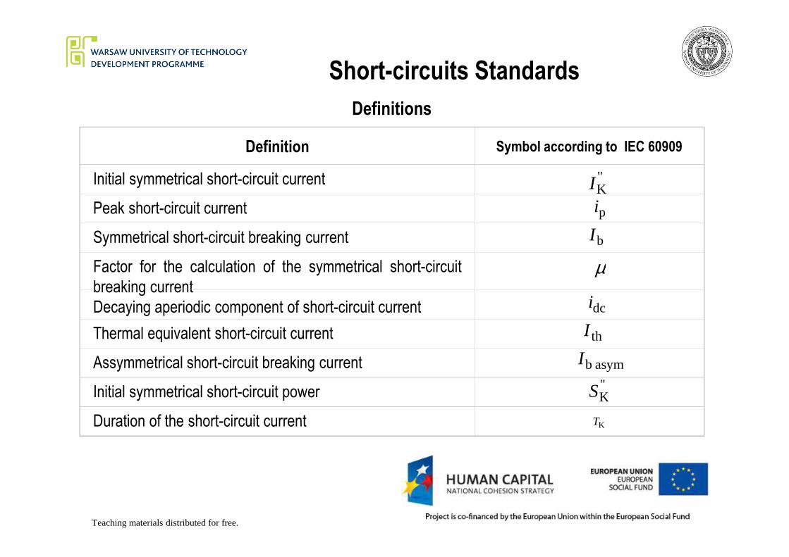
Definitions
Definition Symbol according to IEC 60909
Initial symmetrical short-circuit current
Peak short-circuit current
Symmetrical short-circuit breaking current
Factor for the calculation of the symmetrical short-circuit
breaking current
"KI
pi
bI
µ
Teaching materials distributed for free.
breaking current
Decaying aperiodic component of short-circuit current
Thermal equivalent short-circuit current
Assymmetrical short-circuit breaking current
Initial symmetrical short-circuit power
Duration of the short-circuit current
dci
thI
asymbI"KS
KT

Short-circuits StandardsFig. 1. Schematic diagram of
short-circuit current
(a) short-circuit current of far
from generator short-
circuit with decaying AC
component
(b) short-circuit current of
near to generator short-
circuit with constant AC
2 2
IK
2 2
IK
A
i p
a)Current
1 - top enveloppe
2 - bottom enveloppe
i idc dc - DC component of the short-circuit current
Time
Teaching materials distributed for free.
circuit with constant AC
component.
All the other symbols (A, IK, ip, Idc)
were given in the definitions,
1. Top enveloppe,
2. bottom enveloppe
dc
2 2
I K2
2 I
K
2 2
IK
A
i p
=
b)Current
1 - top enveloppe
2 - bottom enveloppe
i idc dc - DC component of the short-circuit current
Time
Short-circuits Standards
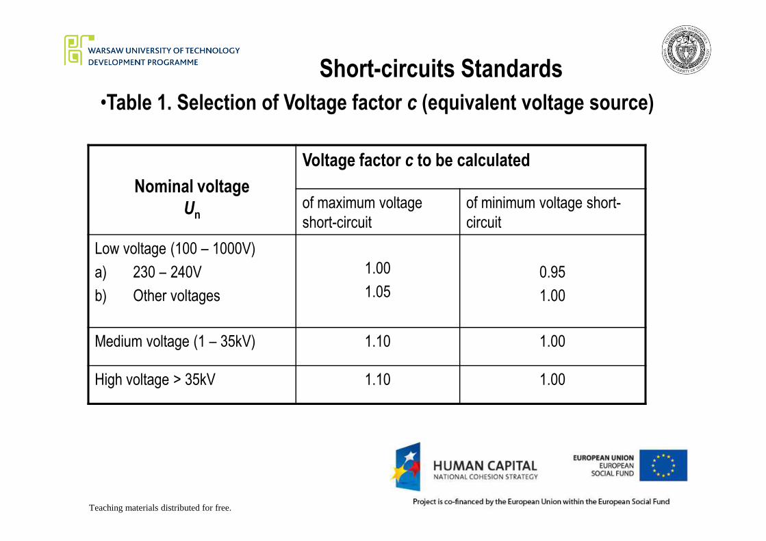
•Table 1. Selection of Voltage factor c (equivalent voltage source)
Nominal voltage
Un
Voltage factor c to be calculated
of maximum voltage
short-circuit
of minimum voltage short-
circuit
Low voltage (100 – 1000V)
a) 230 – 240V 1.00 0.95
Teaching materials distributed for free.
a) 230 – 240V
b) Other voltages
1.00
1.05
0.95
1.00
Medium voltage (1 – 35kV) 1.10 1.00
High voltage > 35kV 1.10 1.00
Short-circuits Standards
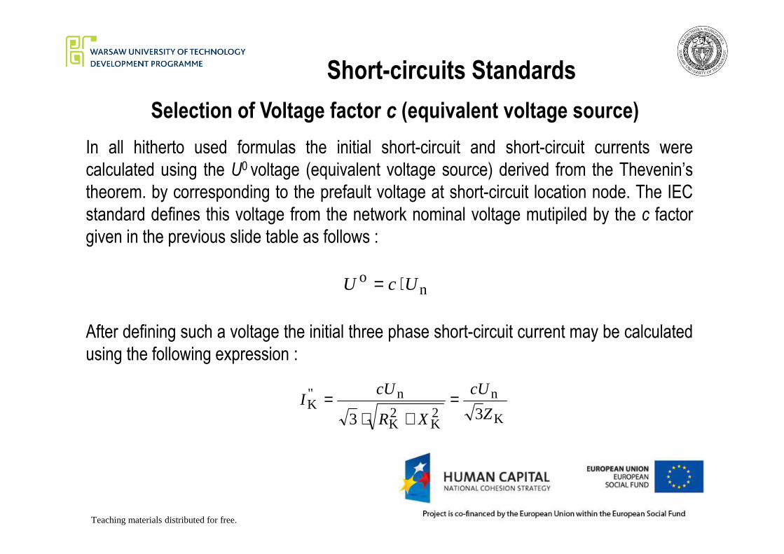
Selection of Voltage factor c (equivalent voltage source)
In all hitherto used formulas the initial short-circuit and short-circuit currents were
calculated using the U0 voltage (equivalent voltage source) derived from the Thevenin’s
theorem. by corresponding to the prefault voltage at short-circuit location node. The IEC
standard defines this voltage from the network nominal voltage mutipiled by the c factor
given in the previous slide table as follows :
o UcU ⋅=
Teaching materials distributed for free.
no UcU ⋅=
After defining such a voltage the initial three phase short-circuit current may be calculated
using the following expression :
K
n
2K
2K
n"K
33 Z
cU
XR
cUI =
+⋅=
Short-circuits Standards
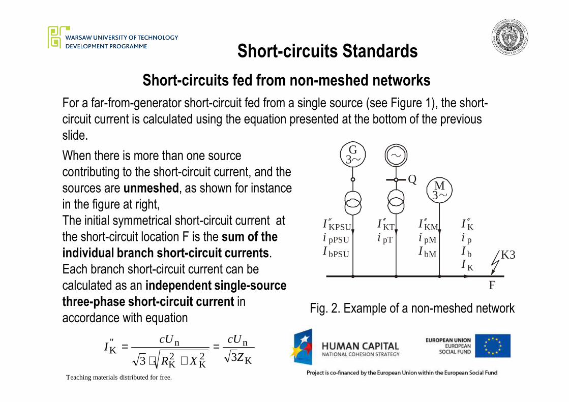
Short-circuits fed from non-meshed networks
For a far-from-generator short-circuit fed from a single source (see Figure 1), the short-
circuit current is calculated using the equation presented at the bottom of the previous
slide.
When there is more than one source
contributing to the short-circuit current, and the
sources are unmeshed, as shown for instance
in the figure at right,
G3
M3
Q
Teaching materials distributed for free.
in the figure at right,
The initial symmetrical short-circuit current at
the short-circuit location F is the sum of the
individual branch short-circuit currents.
Each branch short-circuit current can be
calculated as an independent single-source
three-phase short-circuit current in
accordance with equation
K
n
2K
2K
n"K
33 Z
cU
XR
cUI =
+⋅=
3
F
IiI
KPSU
pPSU
bPSU
Ii
KT
pT
IiI
KM
pM
bM
IiII
K
K
p
b K3
Fig. 2. Example of a non-meshed network
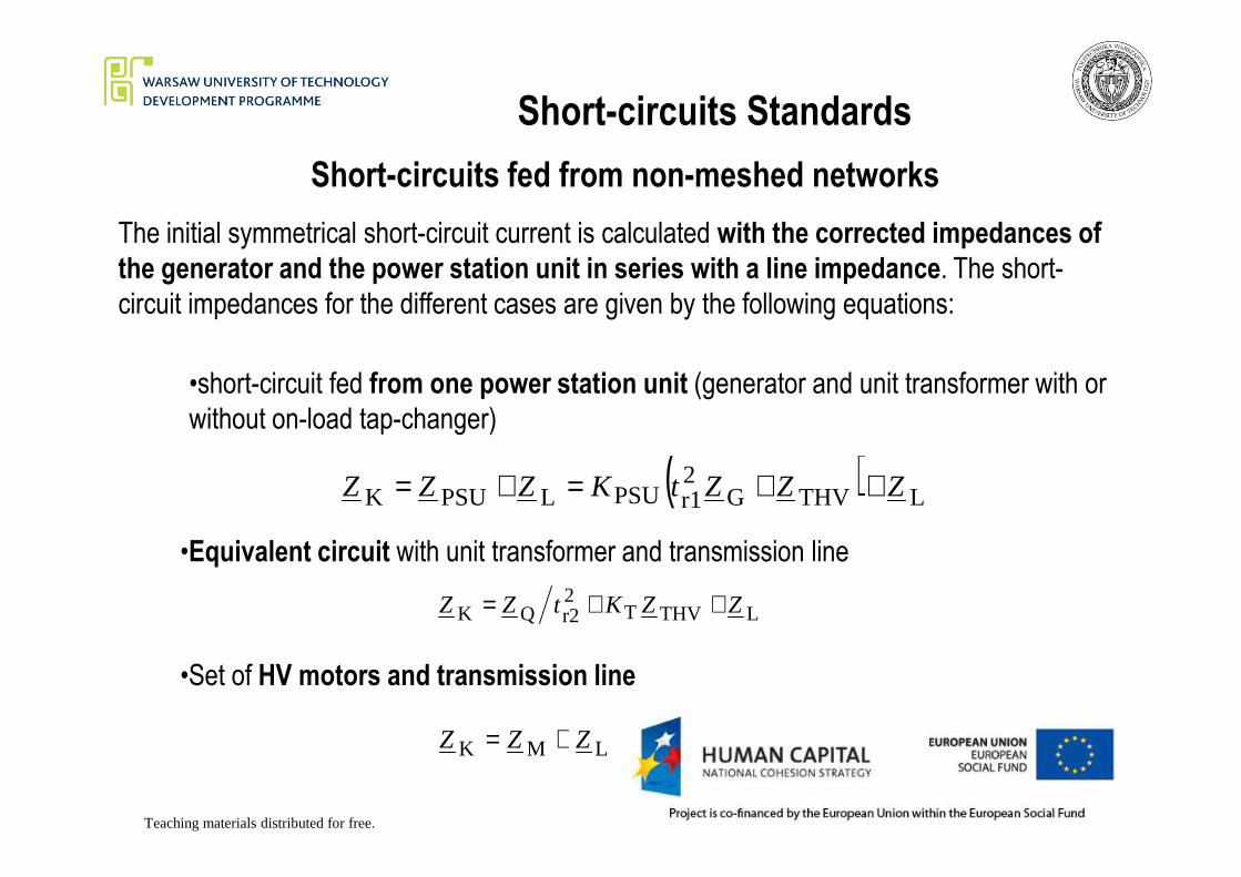
Short-circuits Standards
Short-circuits fed from non-meshed networks
The initial symmetrical short-circuit current is calculated with the corrected impedances of
the generator and the power station unit in series with a line impedance. The short-
circuit impedances for the different cases are given by the following equations:
•short-circuit fed from one power station unit (generator and unit transformer with or
without on-load tap-changer)
Teaching materials distributed for free.
( ) LTHVG2r1PSULPSUK ZZZtKZZZ ++=+=
•Equivalent circuit with unit transformer and transmission line
LTHVT2r2QK ZZKtZZ ++=
•Set of HV motors and transmission line
LMK ZZZ +=

Short-circuits Standards
Short-circuits fed from non-meshed networks
The initial short-circuit current at the short-circuit location F is the phasor sum of the
individual partial short-circuit currents :
∑=i
iII "K
"K
Within the accuracy of this standard, it is often sufficient to determine the short-circuit
Teaching materials distributed for free.
Within the accuracy of this standard, it is often sufficient to determine the short-circuit
current at the short-circuit location F as being the sum of the absolute values of the
individual partial short-circuit currents.
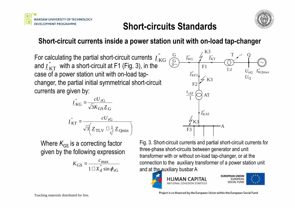
Short-circuits Standards
Short-circuit currents inside a power station unit with on-load tap-changer
For calculating the partial short-circuit currents
and with a short-circuit at F1 (Fig. 3), in the
case of a power station unit with on-load tap-
changer, the partial initial symmetrical short-circuit
currents are given by:
QGG
3
T
F1
AT
K3
K3
trAT
1
F2
KF2I
KGI
KQmaxI
KTI
1:tnQU
QU
rG"KG
cUI =
"KGI
"KTI
Teaching materials distributed for free.
AF3
K3
KATIGGS
KG3 ZK
I =
+=
Qmin1
TLV
rG"KT
2r
3 ZZ
cUI
t
Where KGS is a correcting factor
given by the following expression
rG"d
maxGS
sin1 ϕX
cK
+=
Fig. 3. Short-circuit currents and partial short-circuit currents for
three-phase short-circuits between generator and unit
transformer with or without on-load tap-changer, or at the
connection to the auxiliary transformer of a power station unit
and at the auxiliary busbar A
Short-circuits Standards
Short-circuit currents inside a power station unit with on-load tap-changer
And the rest of the symbols are defined as follows:
ZG is the subtransient impedance of the generator
is the subtransient reactance referred to the rated impedance:"dX
Teaching materials distributed for free.
d
ZTLV is the transformer short-circuit impedance referred to the low-voltage side
tr is the rated transformation ratio;
ZQmin is the minimum value of the impedance of the network feeder, corresponding to
the maximum short-circuit power

Short-circuits Standards
Short-circuit currents inside a power station unit with on-load tap-changer
For the calculation of the partial short-circuit current feeding into the short-circuit
location F2, for example at the connection to the high-voltage side of the auxiliary
transformer AT in the figure, it is sufficient to take:
+
+=
Qmin1
TLVTSGGS
rG"KF2
2
11
3 ZZKZK
cUI
Teaching materials distributed for free.
+ QminTLVTS 2r
ZZKt
With KTS given by the following expression
rGTp.u.
maxTS sin1 ϕX
cK
−=
And KGS as it was given before
rG"d
maxGS
sin1 ϕX
cK
+=
Short-circuits Standards
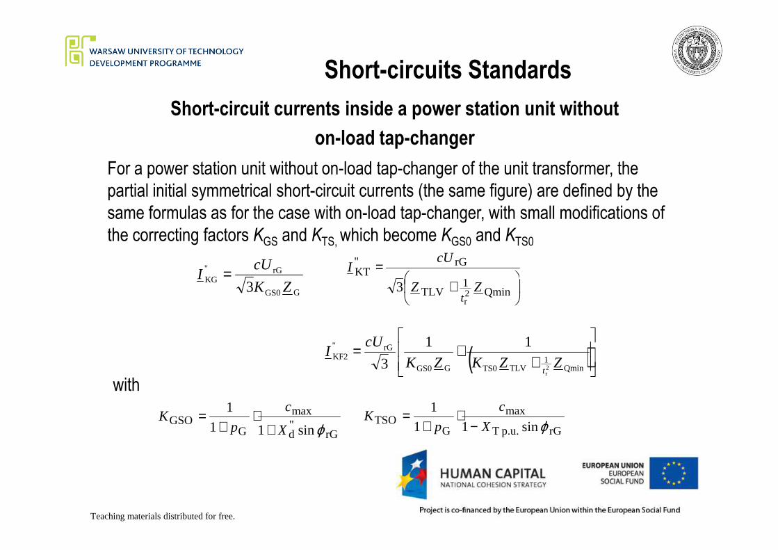
Short-circuit currents inside a power station unit without
on-load tap-changer
For a power station unit without on-load tap-changer of the unit transformer, the
partial initial symmetrical short-circuit currents (the same figure) are defined by the
same formulas as for the case with on-load tap-changer, with small modifications of
the correcting factors KGS and KTS, which become KGS0 and KTS0
rG"KG
cUI =
= rG"KT
cUI
Teaching materials distributed for free.
GGS0
KG3 ZK
I =
+ Qmin1
TLV
KT
2r
3 ZZt
rG"d
max
GGSO
sin1
1
1
ϕX
c
pK
+⋅
+=
rGp.u.T
max
GTSO sin1
1
1
ϕX
c
pK
−⋅
+=
( )
++=
Qmin1
TLVTS0GGS0
rG"KF2
2r
11
3 ZZKZK
cUI
t
with
Short-circuits Standards
Short-circuit currents inside a power station unit without
on-load tap-changer
If the unit transformer has an on-load tap-changer on the high-voltage side, it is
assumed that the operating voltage at the terminals of the generator is equal to UrG.
If, even in this case, the voltage region of the generator UG = UrG(1±pG) is used
permanently, take equations for the case without on-load tap changer than those for
the case with on-load tap changer.
Teaching materials distributed for free.
the case with on-load tap changer.
The total short-circuit current in F1 or F2 is found by adding the partial short-circuit
current, caused by the medium- and low-voltage auxiliary motors of the power
station unit.
Short-circuits Standards
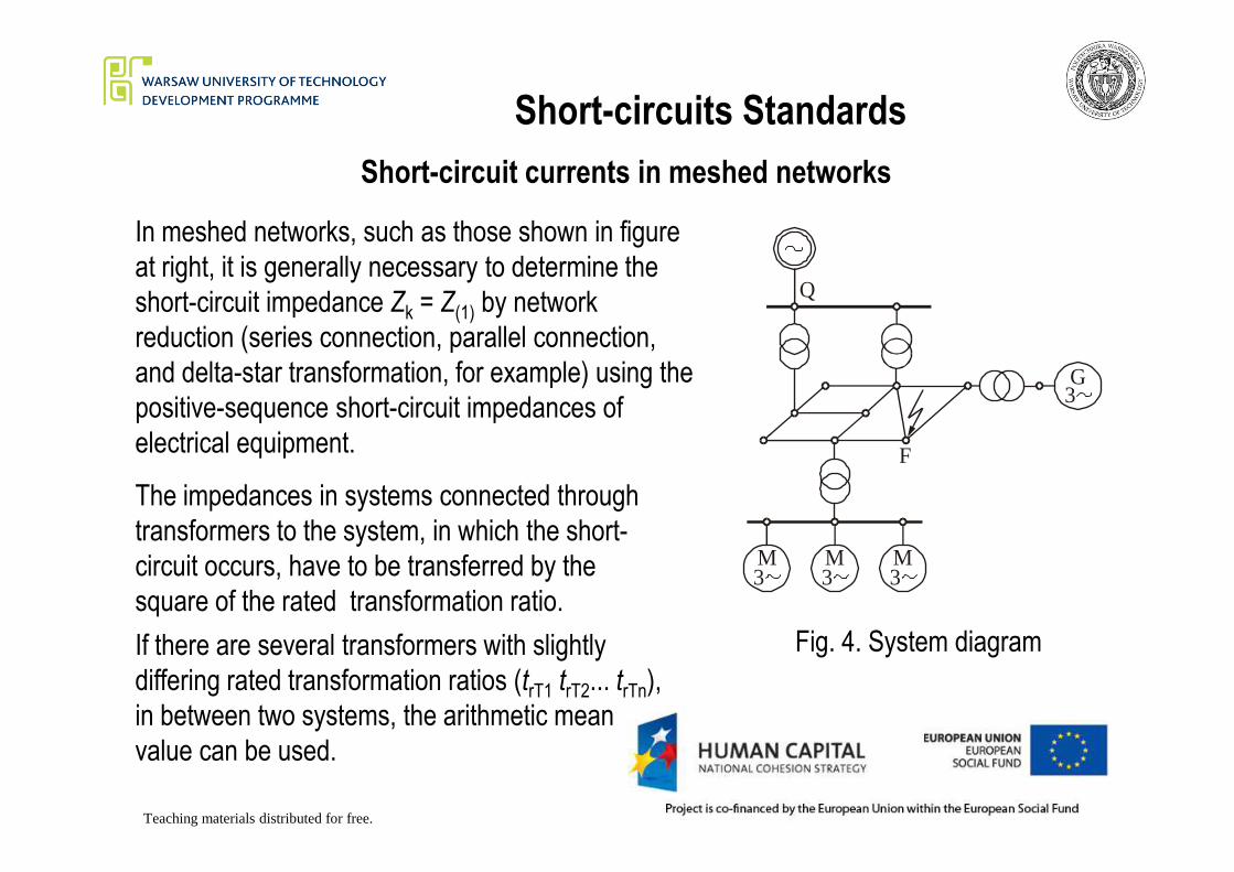
Short-circuit currents in meshed networks
In meshed networks, such as those shown in figure
at right, it is generally necessary to determine the
short-circuit impedance Zk = Z(1) by network
reduction (series connection, parallel connection,
and delta-star transformation, for example) using the
positive-sequence short-circuit impedances of
electrical equipment.
G3
Q
Teaching materials distributed for free.
electrical equipment.
The impedances in systems connected through
transformers to the system, in which the short-
circuit occurs, have to be transferred by the
square of the rated transformation ratio.
M3
M3
M3
F
If there are several transformers with slightly
differing rated transformation ratios (trT1 trT2... trTn),
in between two systems, the arithmetic mean
value can be used.
Fig. 4. System diagram
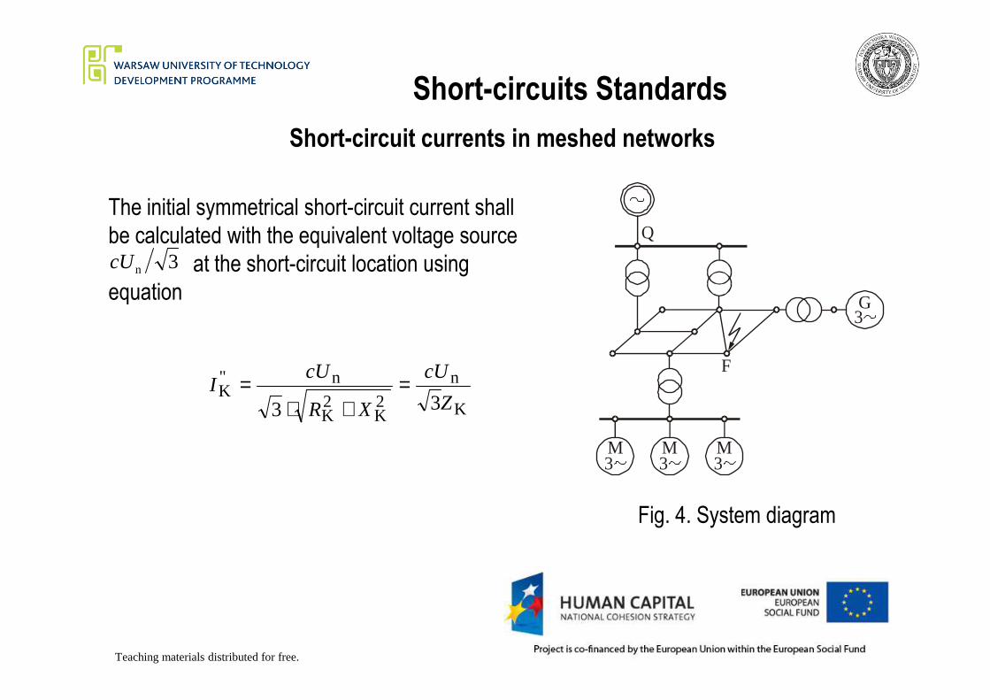
Short-circuits Standards
Short-circuit currents in meshed networks
G3
QThe initial symmetrical short-circuit current shall
be calculated with the equivalent voltage source
at the short-circuit location using
equation
3ncU
Teaching materials distributed for free.
M3
M3
M3
F
Fig. 4. System diagram
K
n
2K
2K
n"K
33 Z
cU
XR
cUI =
+⋅=
Short-circuits Standards
Short-circuit currents in meshed networks
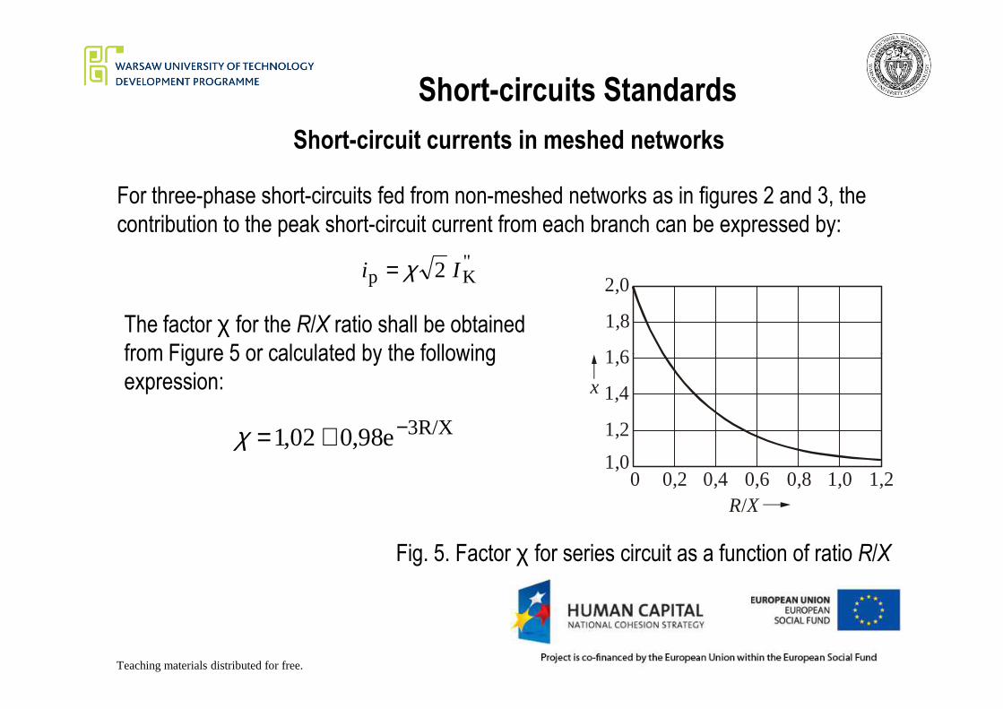
For three-phase short-circuits fed from non-meshed networks as in figures 2 and 3, the
contribution to the peak short-circuit current from each branch can be expressed by:
"Kp 2 Ii χ=
1,6
1,8
2,0
The factor χ for the R/X ratio shall be obtained
from Figure 5 or calculated by the following
Teaching materials distributed for free.
Fig. 5. Factor χ for series circuit as a function of ratio R/X
0 0,2 0,4 0,6 0,8 1,0 1,21,0
1,2
1,4
1,6
x
R X/
from Figure 5 or calculated by the following
expression:
3R/Xe98,002,1 −+=χ
Short-circuits Standards
Short-circuit currents in meshed networks
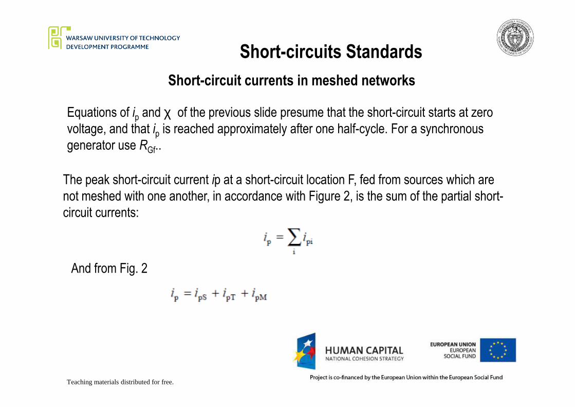
Equations of ip and χ of the previous slide presume that the short-circuit starts at zero
voltage, and that ip is reached approximately after one half-cycle. For a synchronous
generator use RGf..
The peak short-circuit current ip at a short-circuit location F, fed from sources which are
not meshed with one another, in accordance with Figure 2, is the sum of the partial short-
Teaching materials distributed for free.
circuit currents:
And from Fig. 2
Short-circuits Standards
Short-circuit currents in meshed networks
When calculating the peak short-circuit current ip in meshed networks, the equation of ipshall be used with χ determined using one of the following methods a), b), or c).
a) Uniform ratio R/X or X/R
For this method the factor χ is determined from figure 5 taking the smallest ratio of R/X
or the largest ratio of X/R of all branches of the network.
Teaching materials distributed for free.
or the largest ratio of X/R of all branches of the network.
It is only necessary to choose the branches which carry partial short-circuit currents
at the nominal voltage corresponding to the short-circuit location and branches with
transformers adjacent to the short-circuit location.
Any branch may be a series combination of several impedances. In practise,
considering branches, through which the flowing current is about 80% of the short-
circuit current is sufficient.
Short-circuits Standards
Short-circuit currents in meshed networks
b) Ratio R/X or X/R at the short-circuit location
For this method the factor χ is multiplied by a factor 1,15 to cover inaccuracies caused
by using the ratio Rk / Xk from a network reduction with complex impedances.
Teaching materials distributed for free.
The factor χ(b) is found from figure5 for the ratio Rk / Xk given by the short-circuit
impedance Zk = Rk + jXk at the short-circuit location F, calculated for frequency f = 50 Hz
As long as R/X remains smaller than 0,3 in all branches, it is not necessary to use the
factor 1,15. It is not necessary for the product 1,15 . χ(b) to exceed 1,8 in low-voltage
networks or to exceed 2,0 in medium- and high-voltage networks.
Short-circuits Standards
Short-circuit currents in meshed networks
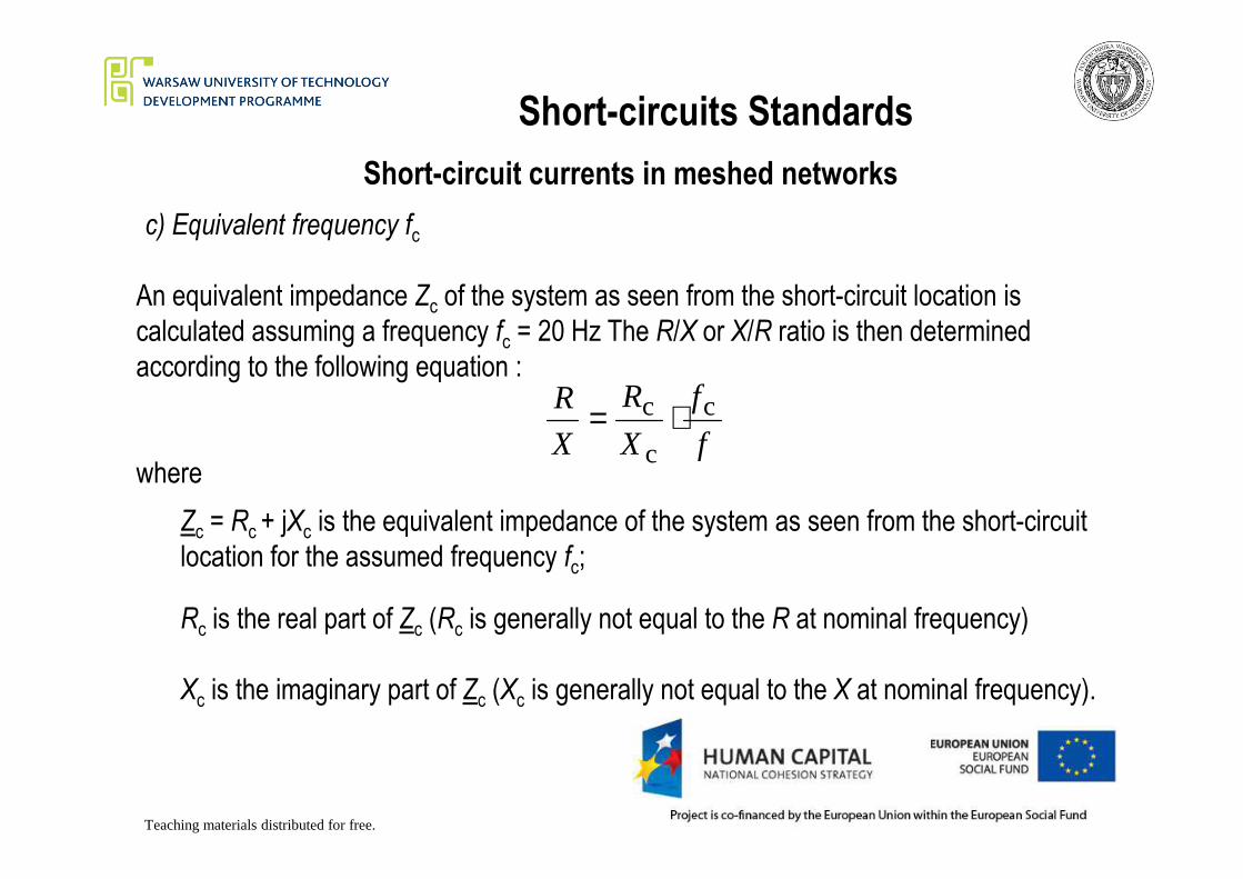
c) Equivalent frequency fc
An equivalent impedance Zc of the system as seen from the short-circuit location is
calculated assuming a frequency fc = 20 Hz The R/X or X/R ratio is then determined
according to the following equation :
f
f
X
R
X
R c
c
c ⋅=
Teaching materials distributed for free.
Zc = Rc + jXc is the equivalent impedance of the system as seen from the short-circuit
location for the assumed frequency fc;
where
Rc is the real part of Zc (Rc is generally not equal to the R at nominal frequency)
Xc is the imaginary part of Zc (Xc is generally not equal to the X at nominal frequency).
fXX c
Short-circuits Standards
Short-circuit currents in meshed networks
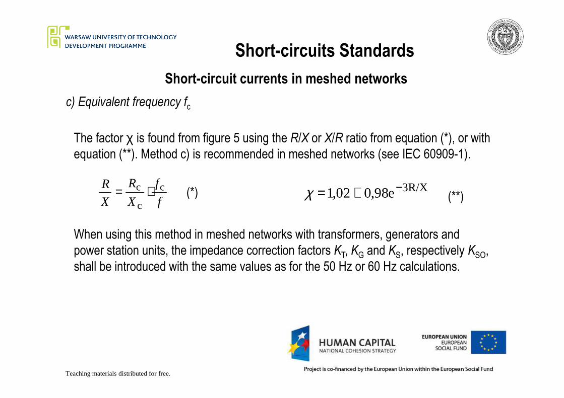
c) Equivalent frequency fc
The factor χ is found from figure 5 using the R/X or X/R ratio from equation (*), or with
equation (**). Method c) is recommended in meshed networks (see IEC 60909-1).
f
f
X
R
X
R cc ⋅= (*) 3R/Xe98,002,1 −+=χ (**)
Teaching materials distributed for free.
When using this method in meshed networks with transformers, generators and
power station units, the impedance correction factors KT, KG and KS, respectively KSO,
shall be introduced with the same values as for the 50 Hz or 60 Hz calculations.
fXX c(*) e98,002,1 +=χ (**)

Short-circuits Standards
Symmetrical short-circuit breaking current:
Single-fed three- phase short-circuit
For a near-to-generator short-circuit, in the case of a single fed short-circuit or from non-
meshed networks (fig. 2), the decay to the symmetrical short-circuit breaking current Ib(*) is taken into account by the factor m according to equations (**).
"Kb II µ=
rG"KG
rG"KG
/300min
/260min
e 51,071,0 s 05,0for -
e 26,084,0 s 02,0for -
II,-
II,-
t
t
+==
+==
µ
µ(*)
(**)The factor m depends on the minimum
Teaching materials distributed for free.
rG"KG
rG"KG
/380min
/320min
min
e 0,940,56 s 0,25for -
e 72,062,0 s 10,0for -
e 51,071,0 s 05,0for -
II,-
II,-
t
t
t
+=≥
+==
+==
µ
µ
µ(**)
The factor m depends on the minimum
time delay tmin and the ratio rG"K / II
where IrG is the rated generator current.
The values of m in equation (**) apply if synchronous machines are excited by rotating
exciters or by static converter exciters (provided, for static exciters, the minimum time
delay tmin is less than 0,25 s and the maximum excitation voltage is less than 1,6 times
rated load excitation-voltage). For all other cases take if the exact value is
unknown.
1=µ

Short-circuits Standards
Symmetrical short-circuit breaking current:
Single-fed three- phase short-circuit
If is not greater than 2, apply for all values of
the minimum time delay tmin. rG
"K / II 1=µ
1,0
0,9
0,8
0,02 s
0,05 s
Minimum time delay tmin
The factor µ may also be obtained from figure 6.
Teaching materials distributed for free.
Fig. 6. Factor µ
For other values of minimum time delay, linear
interpolation between curves is acceptable.
Figure 6 can be used also for compound excited
low-voltage generators with a minimum time
delay tmin not greater than 0,1 s.
0,8
0,7
0,6
0,50 1 2 3 4 5 6 7 8 9
Three-phase short circuit or I /I I /IkG rG kM rM
0,05 s
0,1 s
0,25 s
µ

Short-circuits Standards
Symmetrical short-circuit breaking current:
Single-fed three- phase short-circuitFor three-phase short-circuits in non-meshed networks as in figure 2, the symmetrical
breaking current at the short-circuit location can be calculated by the summation of the
individual breaking current contributions:
whereMb"KTPSU bb IIII ++= "
KMbM IqI µ=
m is taken from equation (** - slide 24) or figure 6 for synchronous generators and
asynchronous motors.
Teaching materials distributed for free.
asynchronous motors.
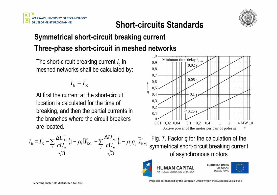
The factor q for the calculation of the symmetrical short-circuit breaking current for
asynchronous motors may be determined as a function of the minimum time delay tmin
(fig. 7).
mqst
mqst
mqst
mqst
ln 10,026,0 25,0for
ln 12,057,0 10,0for
ln 12,079,0 05,0for
ln 12,003,1 02,0for
min
min
min
min
+=≥−+==−+==−+==− Where m is the ratio between is the rated
active power in MW and the number of
pairs of poles of the motor.
pPm /rM=
(*)
Short-circuits Standards
Symmetrical short-circuit breaking current
Three-phase short-circuit in meshed networks
At first the current at the short-circuit
The short-circuit breaking current Ib in
meshed networks shall be calculated by:
"Kb II =
0,4
0,5
0,6
0,7
0,8
0,9
1,0
q
0,02 s
0,05 s
0,1 s
Minimum time delay tmin
Teaching materials distributed for free.
Fig. 7. Factor q for the calculation of the
symmetrical short-circuit breaking current
of asynchronous motors
At first the current at the short-circuit
location is calculated for the time of
breaking, and then the partial currents in
the branches where the circuit breakers
are located.
( ) ( ) "KM
n
"M"
KGn
"G"
Kb 1
3
1
3
jjjj
jii
i
i IqcUU
IcUU
II µµ −∆
−−∆−= ∑∑
0,01 0,02 0,04 0,1 0,2 0,4 1 2 4 10MW0
0,1
0,2
0,3
Active power of the motor per pair of poles m
0,25 s

Short-circuits Standards
Symmetrical short-circuit breaking current
Three-phase short-circuit in meshed networks
where
µi, µj are the values given in equation (** - slide 24) for both synchronous (i) and
asynchronous (j) machines;
q are the values given in equation (* - slide 26) for asynchronous (j) motors;
( ) ( ) "KM
n
"M"
KGn
"G"
Kb 1
3
1
3
jjjj
jii
i
i IqcUU
IcUU
II µµ −∆
−−∆−= ∑∑
Teaching materials distributed for free.
qj are the values given in equation (* - slide 26) for asynchronous (j) motors;
are respectively the initial symmetrical short-circuit current and the symmetrical short-
circuit breaking current with influence of all network feeders, synchronous machines and
asynchronous motors;
are the initial voltage drops at the terminals of the synchronous machines (i)
and the asynchronous motors (j);
"M
"G , ji UU ∆∆
are the contributions to the initial symmetrical short-circuit current from the
synchronous machines (i) and the asynchronous motors (j) as measured at the terminals of
the machines.
"KM
"KG , ji II
"Kb,II
Short-circuits Standards
Symmetrical short-circuit breaking current
IK1IK2
IK3
IK4IK5
IK6I ,IK b
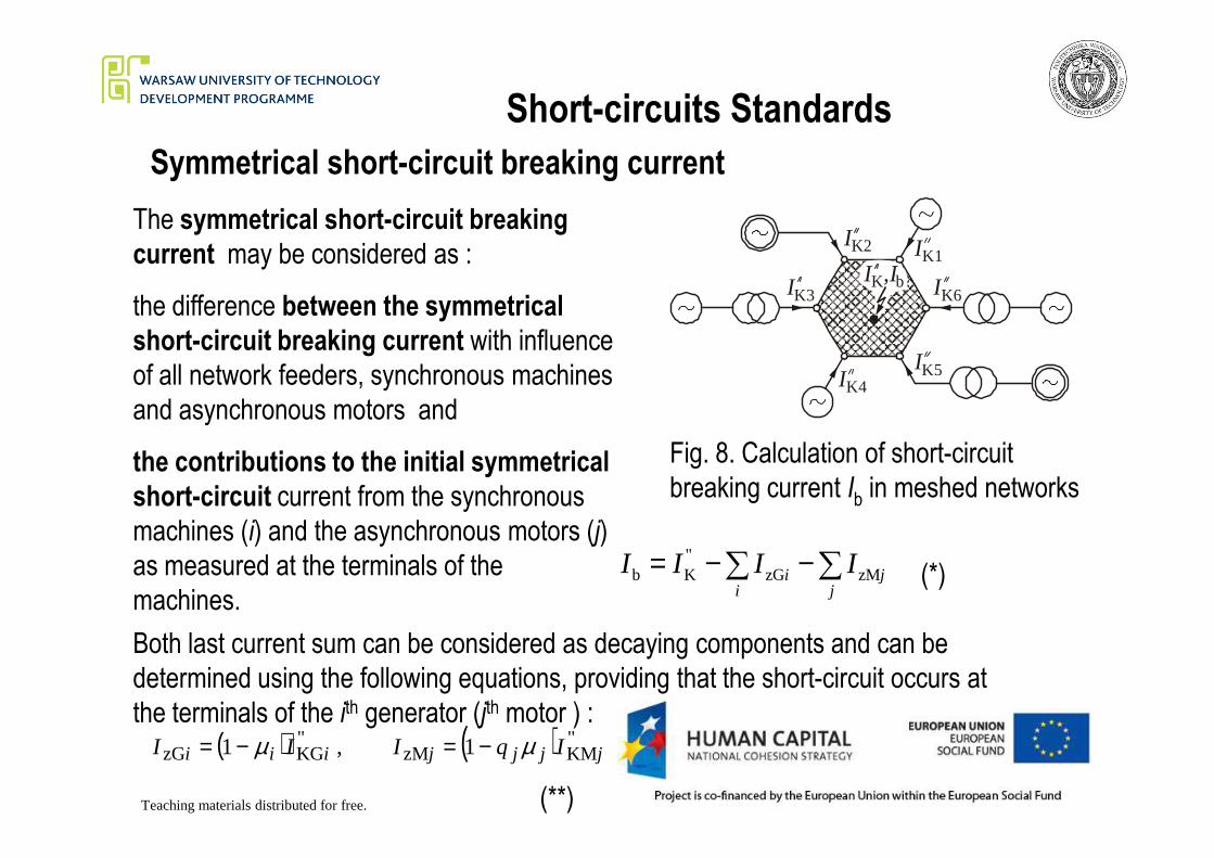
The symmetrical short-circuit breaking
current may be considered as :
the difference between the symmetrical
short-circuit breaking current with influence
of all network feeders, synchronous machines
and asynchronous motors and
Teaching materials distributed for free.
Fig. 8. Calculation of short-circuit
breaking current Ib in meshed networks
∑ ∑−−=i j
ji IIII zMzG"Kb
the contributions to the initial symmetrical
short-circuit current from the synchronous
machines (i) and the asynchronous motors (j)
as measured at the terminals of the
machines.
Both last current sum can be considered as decaying components and can be
determined using the following equations, providing that the short-circuit occurs at
the terminals of the ith generator (jth motor ) :( ) ( ) "
KMzM"KGzG 1 , 1 jjjjiii IqIII µµ −=−=
(*)
(**)

Short-circuits Standards
Symmetrical short-circuit breaking current
(*)
The short-circuit is a far-from-generator short-circuit, hence the decaying process of
the short-circuit current sinusoidal component is dynamic (Fig. 1). We can assume
that the decaying factor is equal to a coefficient αi, which is a real number, the absolute
value of which less than 1 (αj for motors), multiplied by the current defined for near-to-
generator short-circuit.
( ) ( ) "KMzM
"KGzG 1 , 1 jjjjjiiii IqIII µαµα −=−=
Teaching materials distributed for free.
(*)( ) ( ) KMzMKGzG 1 , 1 jjjjjiiii IqIII µαµα −=−=
The coefficient αi defines the distance between the short-circuit location and the
generator terminals (for near-to-generator short-circuits, its value is near 1, for very far-
from-generator short-circuits almost equal to 0).
In case of non-meshed networks this coefficient can be determined in correlation with
the impedance of the portion of line from the short-circuit location and the generator.

Short-circuits Standards
Symmetrical short-circuit breaking current
In case of meshed networks it is difficult to define such a line, then the distance between
the short-circuit location and the generator is assumed as equal to the ration of voltage
drop in the corrected generator (motor) reactance and the network phase voltage, hence.
""" XIU∆ " XIU∆
Teaching materials distributed for free.
3
"dK
"KG
3
"G
n ncUi
cUi
iXIU
=∆
=α33
"
nn cU
MkMj
cU
Mjj
XIU=
∆=α
Considering the equations (* - previous slide), (*) and (**) leads to a new form of the
equation (* - slide nr 28). In case of greater number of voltage sources, it is much more
convenient to use special computer methods for short-circuit calculations.
(*) (**)
Short-circuits Standards
Maximum steady-state short-circuit current
For near-to-generator three-phase short-circuits fed directly from one synchronous generator or
one power station unit only, according to figure 11b or 11c, the steady-state short-circuit current Ikdepends on the excitation system, the voltage regulator action, and saturation influences.
Synchronous machines (generators, motors, or compensators) with terminal-fed static exciters do
not contribute to Ik in the case of a short-circuit at the terminals of the machine, but they
contribute to Ik if there is an impedance between the terminals and the short-circuit location.
A contribution is also given if, in case of a power station unit, the short-circuit occurs on the high-
Teaching materials distributed for free.
For the calculation of the maximum steady-state short-circuit current, the synchronous generator
may be set at the maximum excitation.
For static excitation systems fed from the generator terminals and a short-circuit at the terminals,
the field voltage collapses as the terminal voltage collapses, therefore take λmax = λmin = 0 in this
case.
rGmaxmaxK II λ=
k
A contribution is also given if, in case of a power station unit, the short-circuit occurs on the high-
voltage side of the unit transformer
Short-circuits Standards
Maximum steady-state short-circuit current
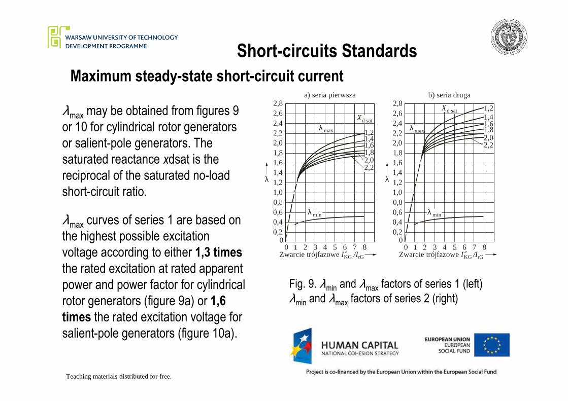
λmax may be obtained from figures 9
or 10 for cylindrical rotor generators
or salient-pole generators. The
saturated reactance xdsat is the
reciprocal of the saturated no-load
short-circuit ratio.
1,21,41,61,82,02,2
1,21,41,61,82,02,2
maxλ maxλd satX
d satX
0,81,01,21,41,61,82,02,22,42,62,8
0,81,01,21,41,61,82,02,22,42,62,8
λ λ
a) seria pierwsza b) seria druga
Teaching materials distributed for free.
minλ minλ
0 1 2 3 4 5 7 80
0,20,40,60,8
6 0 1 2 3 4 5 7 80
0,20,40,60,8
6Zwarcie trójfazowe I /IKG rG Zwarcie trójfazowe I /IKG rG
Fig. 9. λmin and λmax factors of series 1 (left)
λmin and λmax factors of series 2 (right)
λmax curves of series 1 are based on
the highest possible excitation
voltage according to either 1,3 times
the rated excitation at rated apparent
power and power factor for cylindrical
rotor generators (figure 9a) or 1,6
times the rated excitation voltage for
salient-pole generators (figure 10a).

Short-circuits Standards
Maximum steady-state short-circuit current
λ λ
a) seria pierwsza b) seria druga
2,02,53,03,54,04,55,05,5
2,02,53,03,54,04,55,05,5
maxλmaxλd satX
d satX
0,6
0,6
0,8
0,8
1,0
1,0
1,2
1,2
2,01,7
1,72,0
λmax -curves of series 2 are based on the
highest possible excitation-voltage
according to either 1,6 times the rated
excitation at rated apparent power and
power factor for cylindrical rotor
generators (figure 9b), or 2,0 times the
rated excitation voltage for salient-pole
Teaching materials distributed for free.
Fig. 10. λmin and λmax factors of series 1 (left)
λmin and λmax factors of series 2 (right)
rG Zwarcie trójfazowe I /IKG rG
2,0
6Zwarcie trójfazowe I /IKG
6 0 1 2 3 4 5 7 80
0,51,01,5
4 5 7 80
0,51,01,52,0
minλ minλ
0 1 2 3
2,0rated excitation voltage for salient-pole
generators (figure 10b).
λmax -curves of series 1 or 2 may also be
applied in the case of terminal-fed static
exciters, if the short-circuit is at the high-
voltage side of the unit transformer of a
power station unit or in the system, and if
the maximum excitation voltage is chosen
with respect to the partial breakdown of the
terminal voltage of the generator during the
short-circuit.
Short-circuits Standards
Minimum steady-state short-circuit current
For the minimum steady-state short-circuit current in the case of a single-fed short-
circuit from one generator or one power station unit, constant no-load excitation
(voltage regulator not being effective) of the synchronous machine is assumed:
rGminminK IλI =
Teaching materials distributed for free.
λmin may be obtained from figures 9 and 10. In the case of minimum steady-state
short-circuit introduce c = cmin, according to table 1 (slide 5).

Short-circuits Standards
Minimum steady-state short-circuit current
The calculation of the minimum steady-state short-circuit current in the case of a near-
togenerator short-circuit, fed by one or several similar and parallel working generators
with compound excitation, is made as follows:
Teaching materials distributed for free.
For the effective reactance of the generators, introduce:
IkP is the steady-state short-circuit current of a generator at a three-phase terminal
short-circuit. The value should be obtained from the manufacturer.

Short-circuits Standards
DC component of the short-circuit current
The maximum d.c. component id.c. of the short-circuit current as shown in figures 1 and
2 may be calculated with sufficient accuracy by the following equation :
where
XRfteIi /2"Kdc
K 2 π−=
is the initial symmetrical short-circuit current;"KI
Teaching materials distributed for free.
f is the nominal frequency;
t is the time;
R/X s the ratio according to Fig. 5 or the ratios according to the methods a) and c)
slides 19 - 22.
K

Short-circuits Standards
Joule integral and thermal equivalent short-circuit current
The joule integral is a measure of the energy generated in the resistive
element of the system by the short-circuit current. In this standard it is calculated
using a factor m for the time-dependent heat effect of the d.c. component of the
short-circuit current and a factor n for the time-dependent heat effect of the a.c.
component of the short-circuit current (see figures 11 and 12)
Teaching materials distributed for free.
nmII += "Kth
The thermal equivalent short-circuit current is:
Short-circuits Standards
Joule integral and thermal equivalent short-circuit current
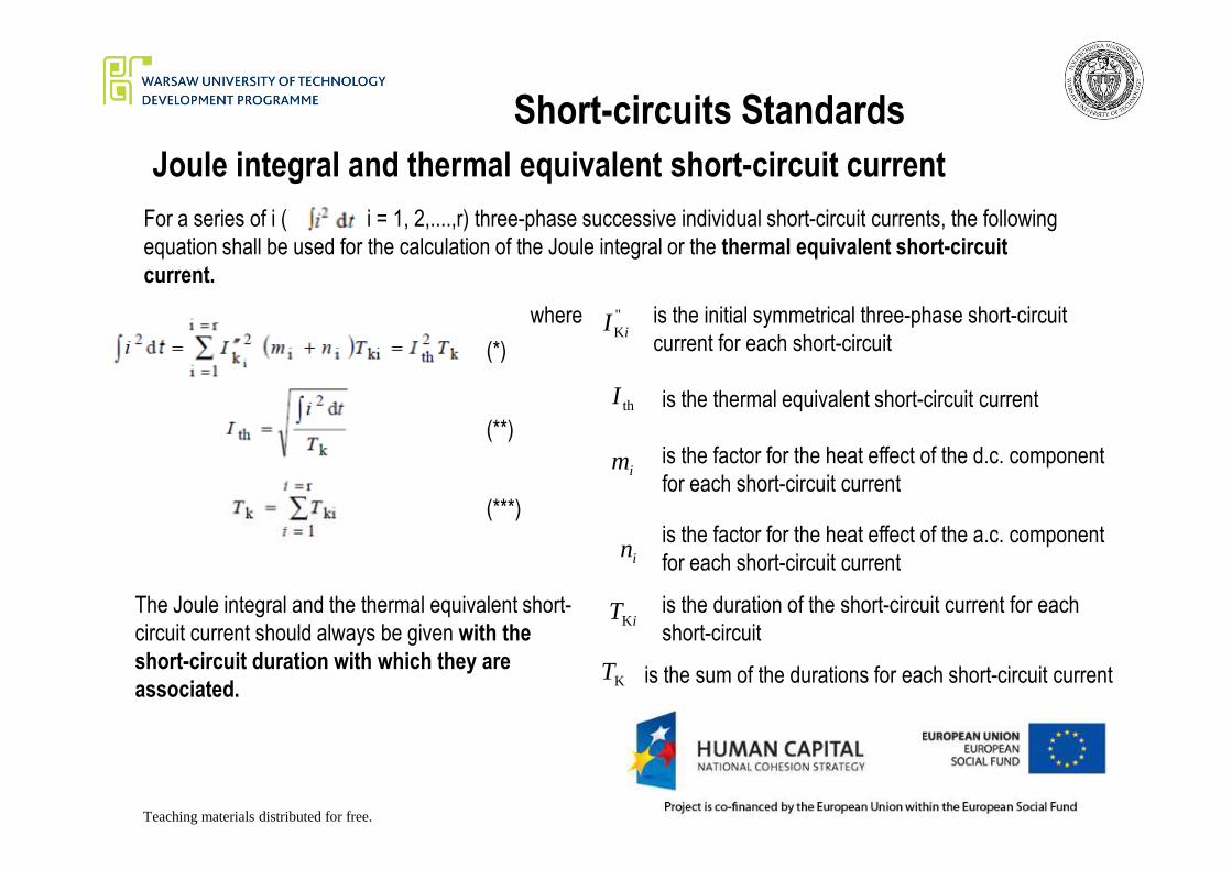
For a series of i ( i = 1, 2,....,r) three-phase successive individual short-circuit currents, the following
equation shall be used for the calculation of the Joule integral or the thermal equivalent short-circuit
current.
where is the initial symmetrical three-phase short-circuit
current for each short-circuit
"KiI
is the thermal equivalent short-circuit currentthI
(*)
(**)
Teaching materials distributed for free.
is the factor for the heat effect of the d.c. component
for each short-circuit currentim
is the factor for the heat effect of the a.c. component
for each short-circuit currentin
is the duration of the short-circuit current for each
short-circuitiTK
is the sum of the durations for each short-circuit currentKT
The Joule integral and the thermal equivalent short-
circuit current should always be given with the
short-circuit duration with which they are
associated.
(**)
(***)
Short-circuits Standards
Joule integral and thermal equivalent short-circuit current
1,6
2,0a)
χ=1,9
1,6
2,0b)
I I / =10K K
1,251,5
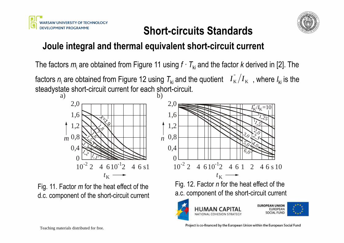
The factors mi are obtained from Figure 11 using f · Tki and the factor k derived in [2]. The
factors ni are obtained from Figure 12 using Tki and the quotient , where Iki is the
steadystate short-circuit current for each short-circuit.K
"K II
Teaching materials distributed for free.
Fig. 11. Factor m for the heat effect of the
d.c. component of the short-circuit current
Fig. 12. Factor n for the heat effect of the
a.c. component of the short-circuit current
10-2 -1102 4 6 2 4 6 s1tK
0
0,4
0,8
1,2
m
=1,91,81,71,61,5
1,41,31,2 1,1
10-2 -1102 4 6 2 4 6 1 2 46 s10tK
0
0,4
0,8
1,2
n
251,52,03,0
4,05,06,0
Short-circuits Standards
Joule integral and thermal equivalent short-circuit current
When a number of short-circuits occur with a short time interval in between them, the
resulting Joule integral is the sum of the Joule integrals of the individual short-circuit
currents, as given in equation (* slide 38)
For distribution networks (far-from-generator short-circuits) usually n=1 can be used.
Teaching materials distributed for free.
For far-from-generator short-circuit with the rated short-circuit duration of 0,5 s or
more, it is permissible to take m + n = 1.
If the Joule integral or the thermal equivalent short-circuit current shall be calculated
for unbalanced short-circuits, replace with the appropriate unbalanced short-
circuit currents.
"KiI
1. Machowski J, Kacejko P. Zwarcia w systemach
elektroenergetycznych (Power System Short-Circuits – in
Polish), Wydawnictwo Naukowo-Techniczne, Warszawa 2002
2. INTERNATIONAL STANDARD IEC 60909-0 „Short-circuit
Bibliography
currents in three-phase a.c. systems” Calculation of currents
Teaching materials distributed for free.