Embed Size (px)
Citation preview

Short – Circuit withstand capability “Transformers for reliable power quality”
Short - Circuit withstand capability Agenda
Fault currents in network and their interaction with transformers
ABB Technology (TrafoStar™) and design consideration to build SC safe transformers
Advanced manufacturing and SC tests experience
Customer considerations to mitigate future risk by using new SC IEC recommendations
ABB recommendations
© Copyright 2012 ABB CUSTOMER CONFIDENTIAL. The data and information discussed and identified in this document are considered ABB Customer Confidential and are not to be reproduced, used or disclosed to third parties without written permission
Short - Circuit withstand capability
Why talking about Fault Currents in network today?
Are Fault Currents affecting Transformers more today?
Who cares about Mechanical Forces in transformers?

Short - Circuit withstand capability
History – Why SC tests ?
SC tests have been used in different countries Customers didn’t get SC safe transformers
SC tests introduced 1950 -1960
SC tests have been debated during the years Many opinions in different countries about the needs and
what one test show
IEC has edited Standards the first about 1976
This discussion about SC test or not SC test seems relevant also today!

What is the overall driver?
Two infrastructure S-curves
1950-1980 Western infrastructure build out
2000- 2020 South & East Asian infrastructure build out and EU replacements/ interconnections
Energy & material prices related to these megatrends
2010 1960 1970 1980 1990 2000
Consolidation
- ABB formed etc - Low material & energy prices
<= Demand gap =>
?
Short - Circuit withstand capability
Networks are today more loaded, new in-feeds as wind power are added
Load flows are changing
Network components are ageing
The network operation conditions have changed, increasing of short circuit power in growing environment such as Asia.
New transformers will see more severe SC duty than before

Short - Circuit withstand capability
How will this affect today's transformer designs?
There is now a trend to save active material and/or design closer to mechanical/electrical limitations.
Does the Industry have defined efficient measures/test Standards to check the mechanical integrity of products like Power Transformers?
New IEC SC standard proposes
Full scale SC Tests
Design review evaluation/verification IEC edition 2006 proposes typical allowable, critical
stresses
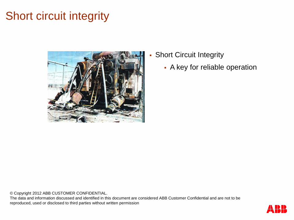
Short Circuit Integrity
A key for reliable operation
Short circuit integrity
© Copyright 2012 ABB CUSTOMER CONFIDENTIAL. The data and information discussed and identified in this document are considered ABB Customer Confidential and are not to be reproduced, used or disclosed to third parties without written permission
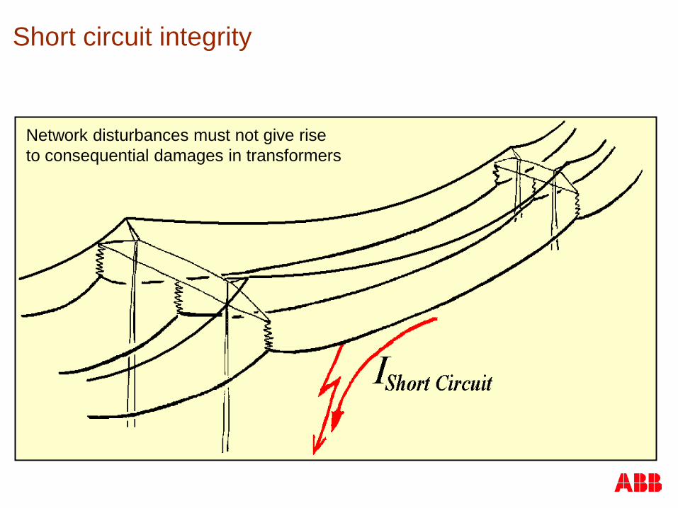
Network disturbances must not give rise to consequential damages in transformers
Short circuit integrity
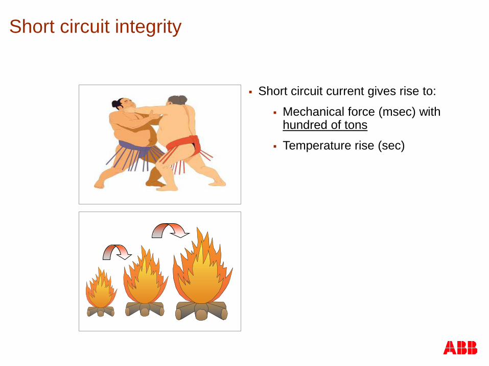
Short circuit current gives rise to:
Mechanical force (msec) with hundred of tons
Temperature rise (sec)
Short circuit integrity
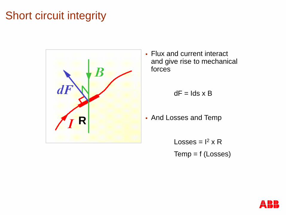
Flux and current interact and give rise to mechanical forces
dF = Ids x B
And Losses and Temp
Losses = I2 x R
Temp = f (Losses)
R
Short circuit integrity
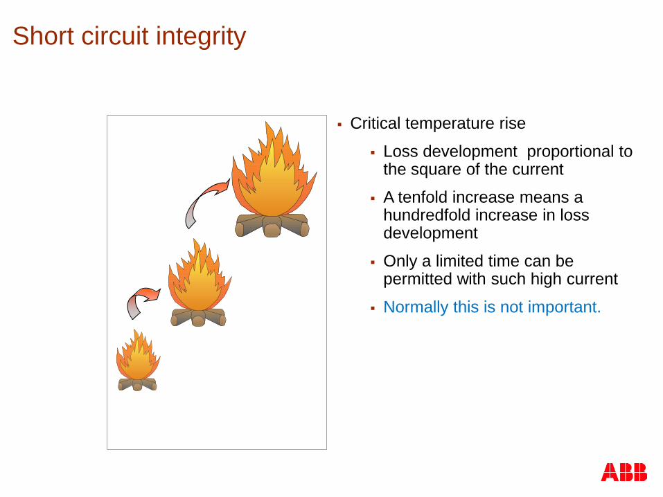
Critical temperature rise
Loss development proportional to the square of the current
A tenfold increase means a hundredfold increase in loss development
Only a limited time can be permitted with such high current
Normally this is not important.
Short circuit integrity
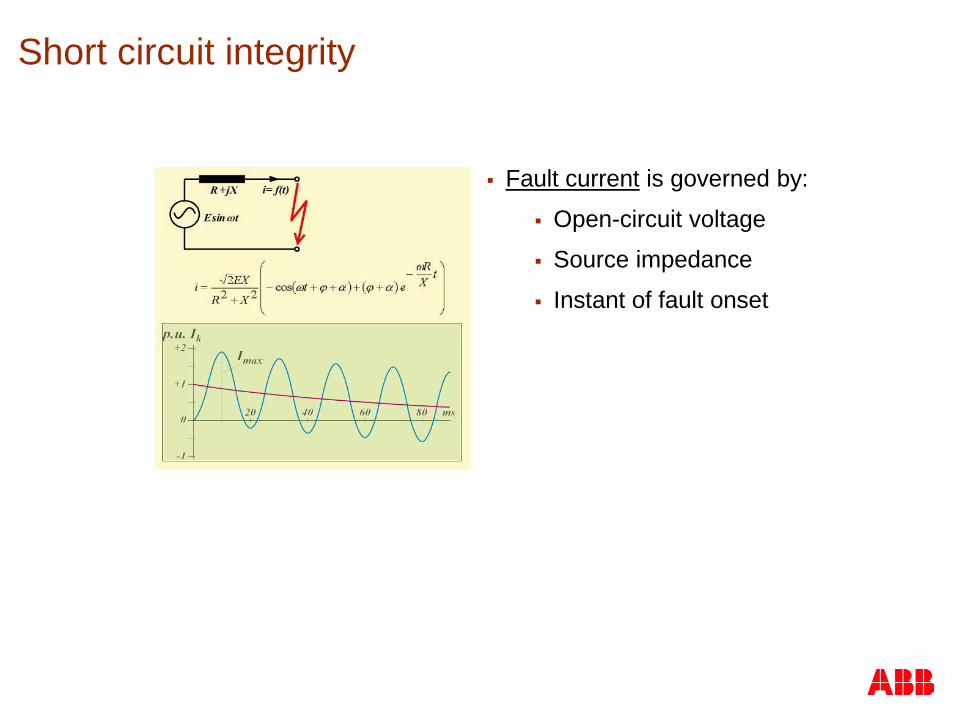
Fault current is governed by:
Open-circuit voltage
Source impedance
Instant of fault onset
Short circuit integrity
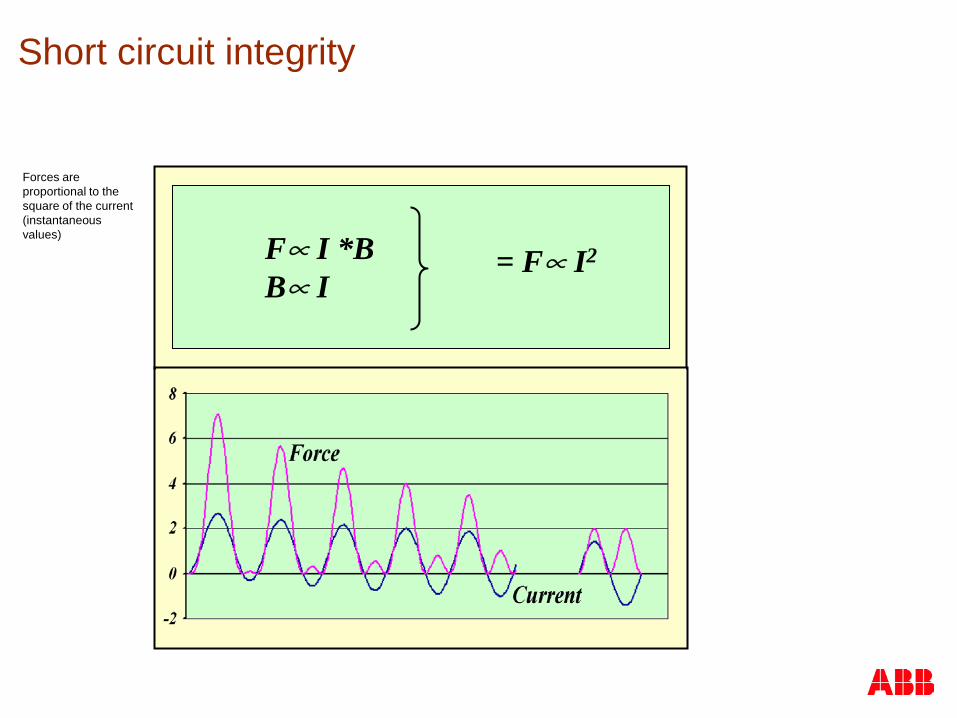
F∝ I *B B∝ I
= F∝ I2
Forces are proportional to the square of the current (instantaneous values)
Short circuit integrity
Risk for Short Circuit Failure depends mainly on
Source impedance
Instant of the fault onset Those factors give the current peak and the final force
Therefore fault currents in service operations often do not load the transformer with the maximum force. The likelihood is that forces of 20-40 % of the max theoretical forces will be seen.
Short circuit integrity
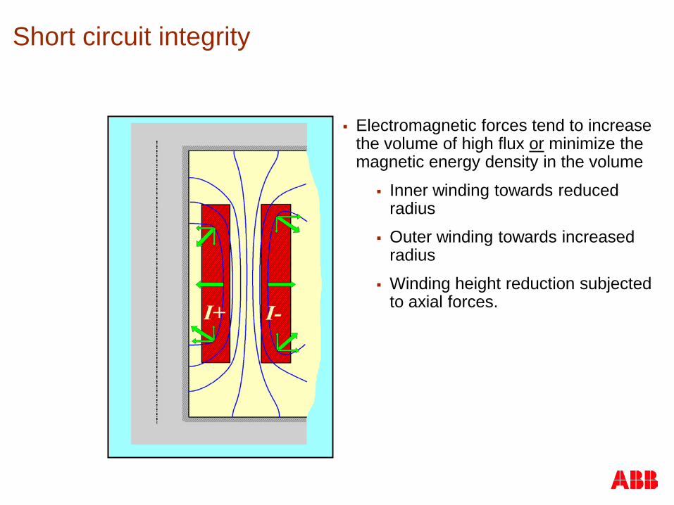
Electromagnetic forces tend to increase the volume of high flux or minimize the magnetic energy density in the volume
Inner winding towards reduced radius
Outer winding towards increased radius
Winding height reduction subjected to axial forces.
Short circuit integrity

The axial component of the leakage flux creates forces in radial direction
Short circuit integrity

Radial forces failure modes:
Buckling of inner winding
Diameter increase of outer winding
Spiralling of end turns in helical winding
Short circuit integrity

Inner winding:
Radial forces inwards
⇒ compressive stress
Short circuit integrity
Outer winding:
Radial forces outwards
⇒ tensile stress
Innerwinding
Outerwinding

Fmean
Force distribution across the inner and outer windings
Conclusion
For withstand analysis the mean value across a winding can be used
Short circuit integrity
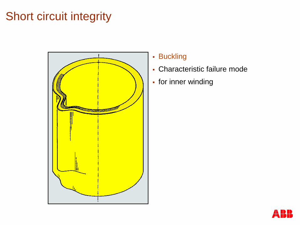
Buckling
Characteristic failure mode
for inner winding
Short circuit integrity
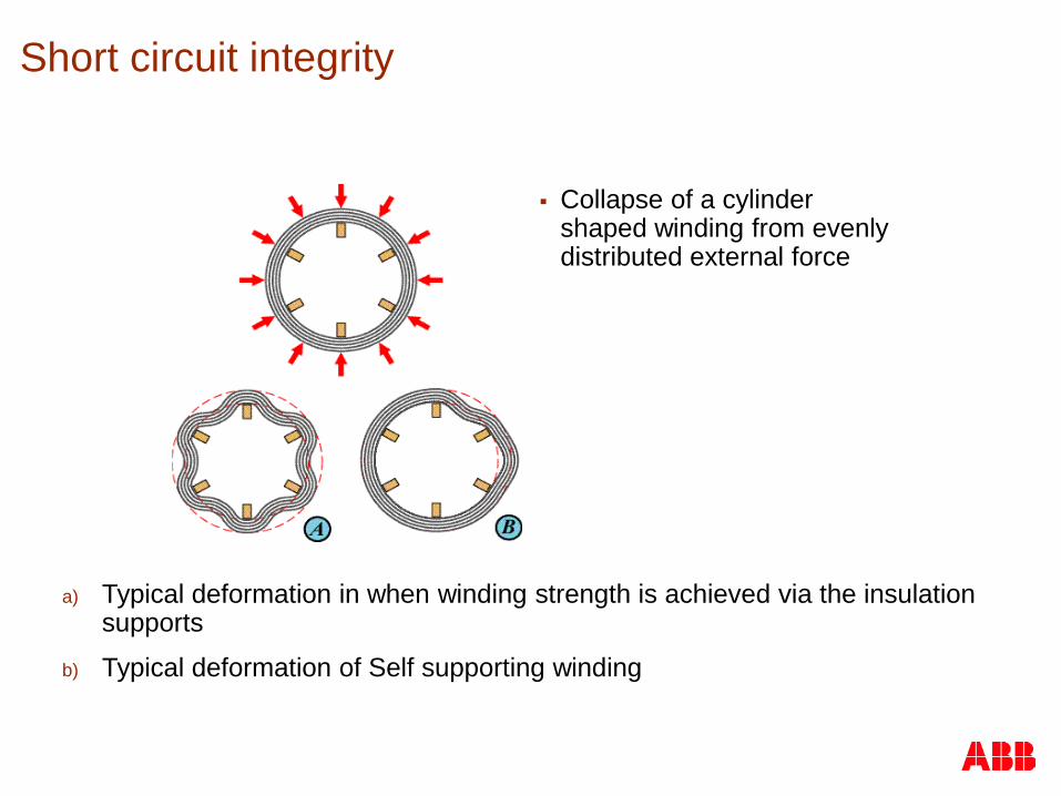
Collapse of a cylinder shaped winding from evenly distributed external force
Short circuit integrity
a) Typical deformation in when winding strength is achieved via the insulation supports
b) Typical deformation of Self supporting winding
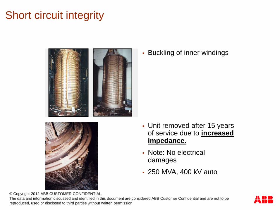
Buckling of inner windings
Unit removed after 15 years of service due to increased impedance.
Note: No electrical damages
250 MVA, 400 kV auto
Short circuit integrity
© Copyright 2012 ABB CUSTOMER CONFIDENTIAL. The data and information discussed and identified in this document are considered ABB Customer Confidential and are not to be reproduced, used or disclosed to third parties without written permission
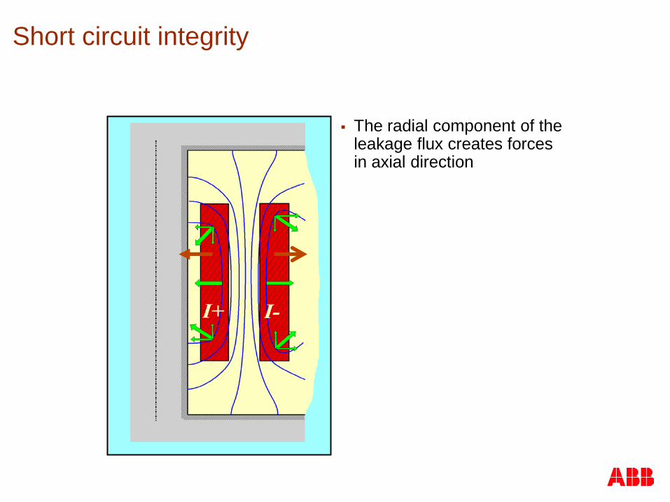
The radial component of the leakage flux creates forces in axial direction
Short circuit integrity
B B Fax Fax
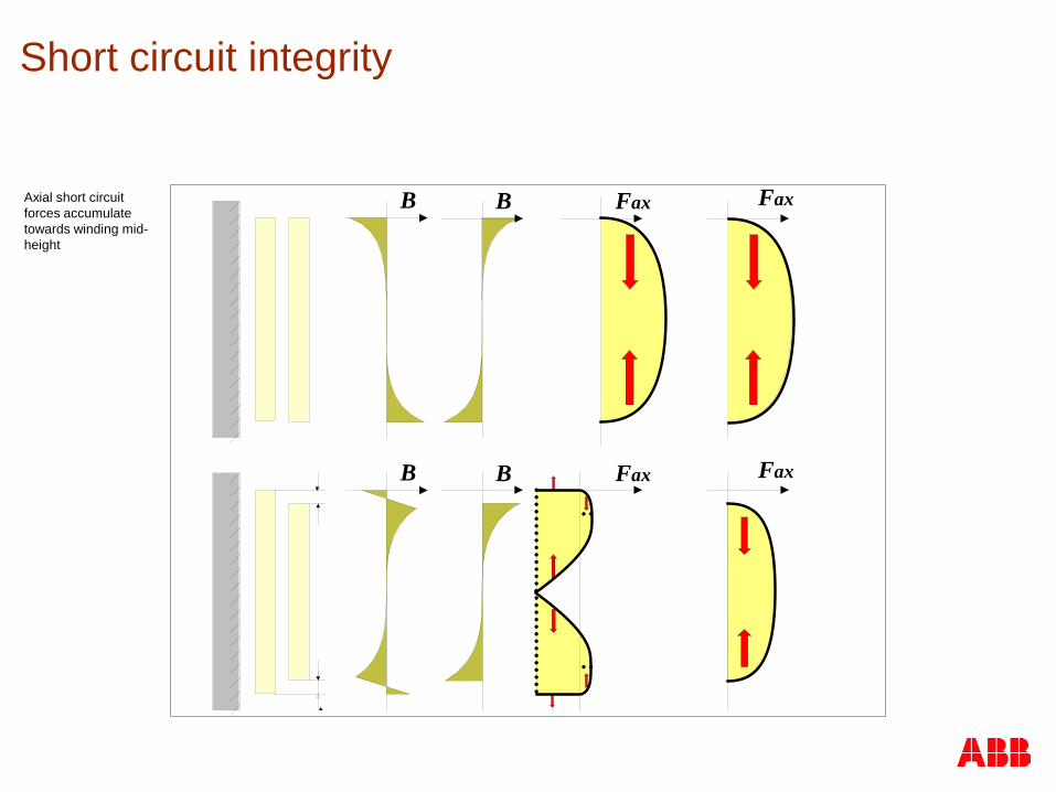
B B Fax FaxAxial short circuit forces accumulate towards winding mid-height
Short circuit integrity
B B Fax Fax
B B Fax Fax
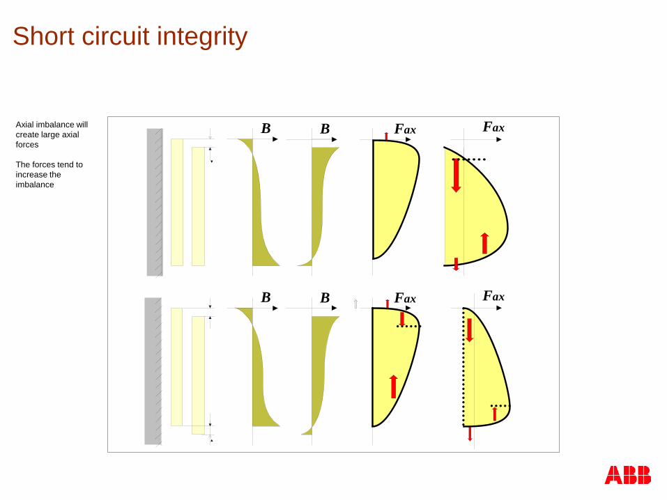
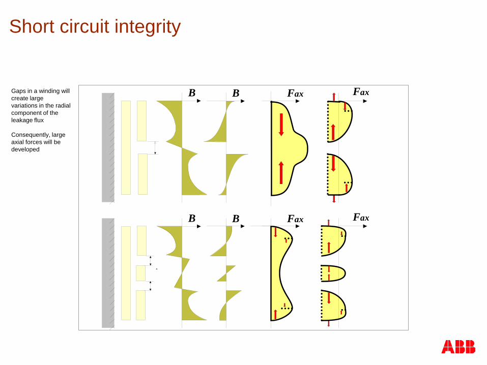
Axial imbalance will create large axial forces The forces tend to increase the imbalance
Short circuit integrity
B B Fax Fax
B B Fax FaxGaps in a winding will create large variations in the radial component of the leakage flux Consequently, large axial forces will be developed
Short circuit integrity
The failure modes for axial forces include:
Mechanical withstand of yoke insulation, core clamps and spacers
Conductor tilting
Axial bending between spacers
Spiralling
Short circuit integrity
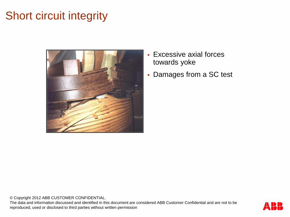
Excessive axial forces towards yoke
Damages from a SC test
Short circuit integrity
© Copyright 2012 ABB CUSTOMER CONFIDENTIAL. The data and information discussed and identified in this document are considered ABB Customer Confidential and are not to be reproduced, used or disclosed to third parties without written permission
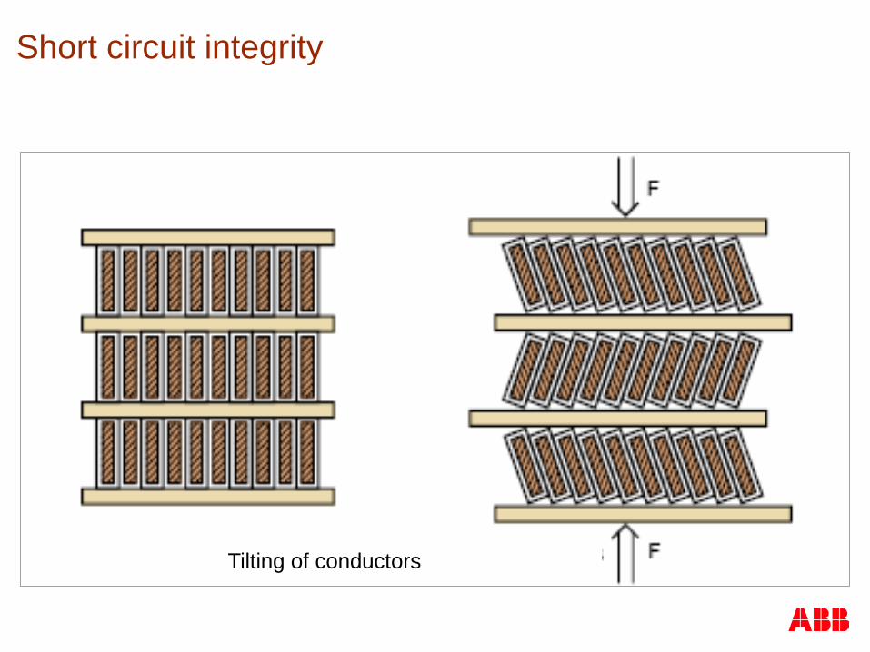
Tilting of conductors
Short circuit integrity
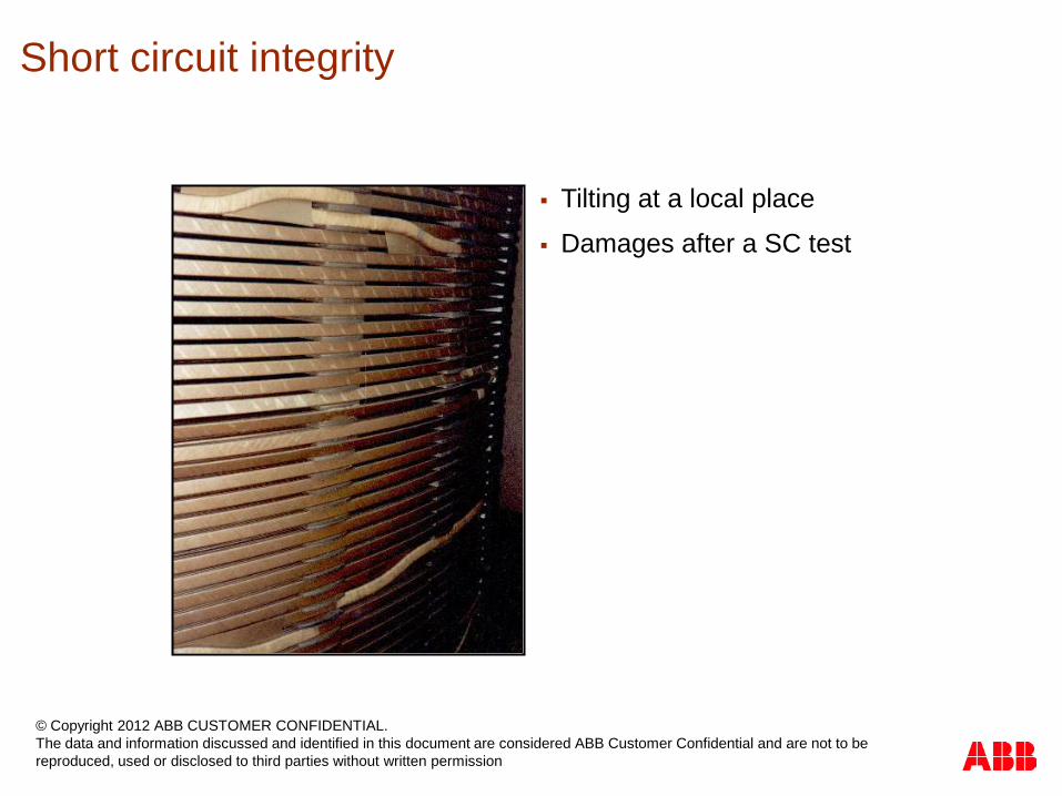
Tilting at a local place
Damages after a SC test
Short circuit integrity
© Copyright 2012 ABB CUSTOMER CONFIDENTIAL. The data and information discussed and identified in this document are considered ABB Customer Confidential and are not to be reproduced, used or disclosed to third parties without written permission
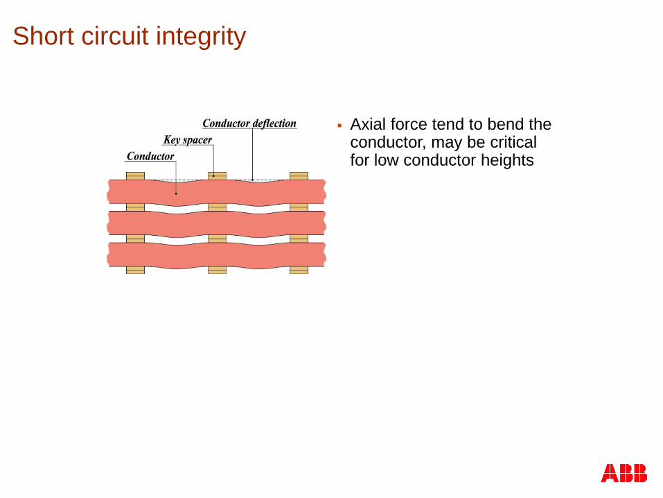
Axial force tend to bend the conductor, may be critical for low conductor heights
Short circuit integrity
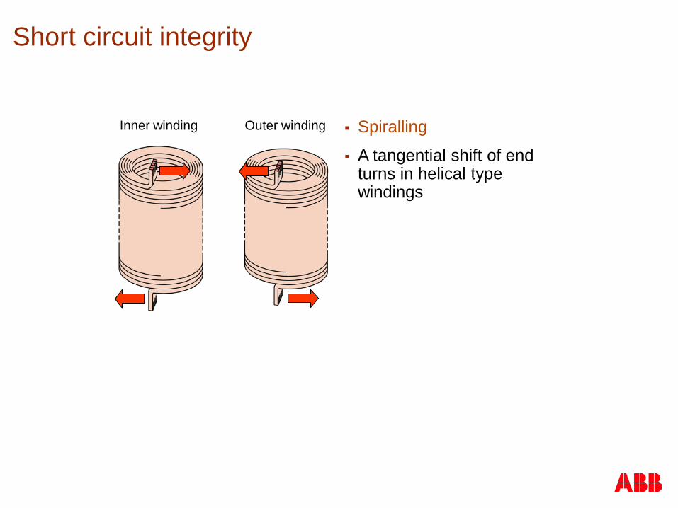
Inner winding Outer winding Spiralling
A tangential shift of end turns in helical type windings
Short circuit integrity

Alternative view of spiralling
Short circuit integrity
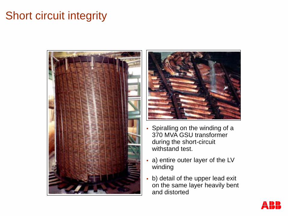
Spiralling on the winding of a 370 MVA GSU transformer during the short-circuit withstand test.
a) entire outer layer of the LV winding
b) detail of the upper lead exit on the same layer heavily bent and distorted
Short circuit integrity
Designing for short-circuit strength - background
Each company forming ABB has performed a large number of short circuit tests forming the basis for its design standards
The “Merger-projects” evaluated the different Power Transformer technologies and standards
In each area; Buckling, Tension, Compression, Tilting, etc the various standards were compared against actual test results.
The standards and principles that were found most relevant and safe were adopted
A new ABB Technical Standard was issued containing the agreed “best practices”
This Standard is adopted worldwide in the TrafoStar™ concept
The TrafoStar concept has been proven by 49 full scale tests since 97
The Standard is continuously improved as a result of new findings
Designing for short-circuit strength
ABB is designing and manufacturing all transformers as if they would be SC tested
Design features of the ABB windings:
All windings are radial self supporting
Spiralling of windings is prevented
Dynamic response of the winding is considered
Designing for short-circuit strength
To verify the strength of a winding ABB considers all failure modes with the currents and forces as at a real SC test:
Radial buckling
Radial tension
Axial tilting
Axial bending
Axial forces against core yokes
+
All forces on Cleats and Lead structures from Winding exits to Bushings
Designing for short-circuit strength
Design with respect to radial forces:
All windings are radially self supporting
Inner windings are subject to “free buckling” No radial support
A dynamic phenomenon
Strength is determined by Cu hardness (yield point) and conductor geometry
Outside windings are subject to tension Strength is determined by Cu hardness
Designing for short-circuit strength
Design with respect to axial forces:
Axial forces are calculated by FEM Considering axial displacement due to workshop
tolerance
Considering axial displacement due to winding pitch when applicable
Windings are dimensioned for maximum compression forces
Dynamic effects are considered by dynamic factors on the forces
Winding ends are dimensioned for Maximum unbalance forces
A part of the maximum compression force (“Bounce Back”)
Designing for short-circuit strength
Designing Power Transformers is an iteration and interaction process to find an optimal solution from
Weights and Losses
Short Circuit Strength (see all earlier SC cases)
Temperatures and winding hot spots and cooling equipment
Dielectric strength between windings and inside windings
As a support the ABB designer has the worlds most advanced set of design and verification programs for Power Transformers, totally interactive and used today in 13 transformer plants. “TrAce” for SC design.
The TrafoStar™ concept is developed and maintained by a dedicated team of about 50 engineers

Manufacturing aspects and accuracy
Work hardening and epoxy coating of conductors when needed
Ampere-turn balancing Max axial displacement < 0.3 % of winding height
Strict manufacturing tolerances for windings Winding height + 0 – 2 mm
Inner diameter controlled by ABB mandrels +2 – 0 mm
Outer diameter -1 – 0 mm
Rigid clamping of windings Twice at the winding work with above tolerances
Once at the final pressing after VP drying with temperature control to match the real spring constant for each winding
Six Sigma measurements for feedback into the TrafoStar™ system
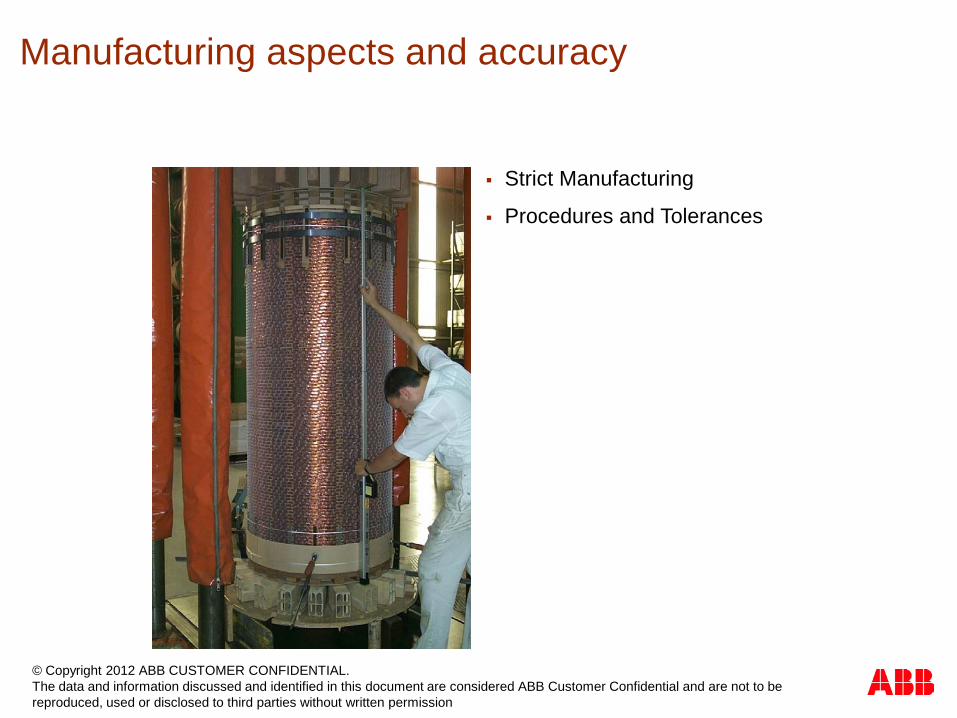
Strict Manufacturing
Procedures and Tolerances
Manufacturing aspects and accuracy
© Copyright 2012 ABB CUSTOMER CONFIDENTIAL. The data and information discussed and identified in this document are considered ABB Customer Confidential and are not to be reproduced, used or disclosed to third parties without written permission

Short circuit strength verification
IEC gives two options to verify the ability to withstand the dynamic effects of a Short Circuit, IEC 60076 – 5: (2006-2)
By full SC test at a certified lab
By theoretical evaluation of the ability to withstand a SC event by manufacturer’s experiences supported by IEC guidelines

Outstanding SC strength test record
More than 140 ABB power transformers of different designs have passed short-circuit tests 49 of which using TrafoStar™ technology.
The world’s largest short-circuit tested transformer was manufactured by ABB
No other manufacturer has such an extensive test record

Short circuit tests
Arial view of KEMA in the Netherlands
The SC Test requires high power laboratories, accredited, only a handful are available
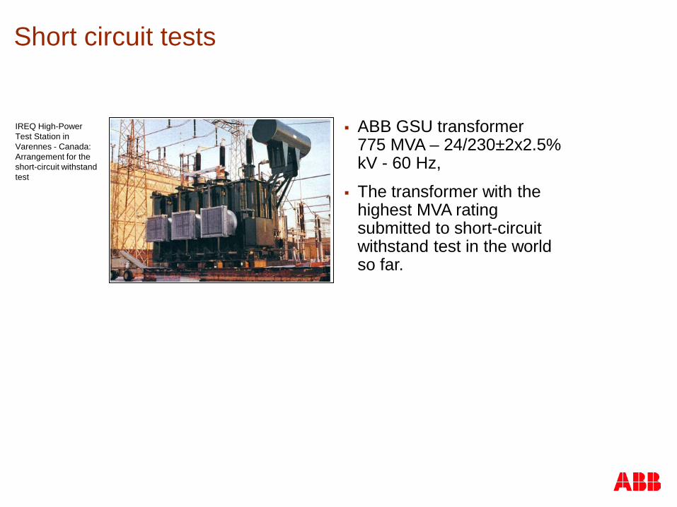
IREQ High-Power Test Station in Varennes - Canada: Arrangement for the short-circuit withstand test
Short circuit tests
ABB GSU transformer 775 MVA – 24/230±2x2.5% kV - 60 Hz,
The transformer with the highest MVA rating submitted to short-circuit withstand test in the world so far.
Short circuit tests
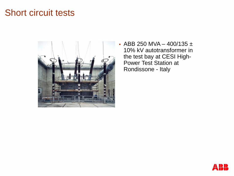
ABB 250 MVA – 400/135 ± 10% kV autotransformer in the test bay at CESI High-Power Test Station at Rondissone - Italy

ABB Zhongshan Transformer Company
220kV 240MVA power transformer Transformer type: SFSZ11-240000/220
Planning date of testing: November 2012
Laboratory: Shenyang Transformer Institute Co., Ltd Transformer Laboratory
Short-circuit tests ABB transformer in China
ABB Zhongshan Transformer Company
110kV 63MVA power transformer Transformer type: SZ11-63000/110
Date of testing: April 2011
Laboratory: Shenyang Transformer Institute Co., Ltd. Transformer Laboratory
CNZTC © ABB Group May 20, 2013 | Slide 50
ABB Hefei Transformer Company
220kV 240MVA power transformer Transformer type: SFSZ11-240000/220
Planning date of testing: November 2012
Laboratory: Shenyang Transformer Institute Co., Ltd. Transformer Laboratory

0
50
100
150
200
250
300
350
1997 2000 2001 2002 2005 2007 2008 2011 2012
Rat
ed M
VA
49 TrafoStar short-circuit tested 1997 – May 2012 14 with voltage 400 kV or above 12 rail track feeder transformers 5 test failures 44 / 49 = 90 % first pass rate
TrafoStar short circuit strength – Verification by testing
© Copyright 2012 ABB CUSTOMER CONFIDENTIAL. The data and information discussed and identified in this document are considered ABB Customer Confidential and are not to be reproduced, used or disclosed to third parties without written permission

Short circuit tests at KEMA KEMA numbers published at CIGRE 2006
25 -30% of large transformers (> 25 MVA) fail to pass initially short-circuit tests.
The10% ABB TrafoStar™ fail to pass initially short-circuit tests.
No common root-cause
0
4
8
12
16
20
25-50 50-100 100-200 >200
MVA (rated)
nu
mb
er
of tr
an
sfo
rme
rs initially not OK
initially OK
0
4
8
12
16
20-100 100-200 200-300 300-400 >400
kV (rated)
nu
mb
er
of tr
an
sfo
rme
rs initially not OK
initially OK
Short circuit tests: Verification Criteria
The following three criteria are recommended by IEC:
Variation in Short Circuit impedance
Successful repetition of routine test
No visible physical damages to the active part
Additionally
Frequency response analysis
Low voltage impulse
Short - circuit withstand capability
From the statistics it seems that ABB has less SC test failures the other suppliers
ABB has done the most number of tests during the years and have got a large amount of feedback and experience
ABB is using simple physical rules to calculate forces and applies modest critical stresses
ABB has stringent manufacturing control on winding related dimensions and processes

SC strength evaluation by IEC guidelines
Theoretical evaluation of the ability to withstand the dynamic effects of short circuit by either:
Design Review where forces and stresses are compared with a SC tested Reference Transformer from the Manufacturer.
Design Review by checking against the manufacturer’s design rules for SC stresses
Stresses shall not exceed manufacturers allowable stresses or 0.8 of the critical stress value identified by the manufacturer
The stresses shall be compared to the stress guidance in the new IEC norm
A SC safe transformer?
What characterize a SC safe Transformer?
Mechanical sound Design and Technology Based on fundamental mechanics
Verified by many SC tests
Rigid core clamping structure for SC strength and transport
Accurate Manufacturing guided by Tolerances and Quality Systems
Rigid winding mandrels
Verified Drying and Pressing Procedures
Rigid LV clamping and procedures
ABB Short circuit recommendation
All transformers are high voltage tested
Some very few are SC tested
Customers shall consider in tender documentations to include new 60076-5@IEC:2006
Always to require manufacturers’ stresses compared with their allowed or critical values, deviations to IEC guidelines to be commented. Design reviews to be required.
As alternative require a full scale S.C.

What units to be SC tested ?
High value units like GSUs, key node Network Transformers 3 winding system transformers (Tertiary), Autos
Series of transformers, just one to be S.C. tested.
Always Track feeding transformers
Transformers connected to networks known for many faults and high fault currents
All Power Transformers designs/contracts to be checked by design reviews acc to IEC 76 Part 5 (2006-02)
ABB Short circuit recommendation