Embed Size (px)
Citation preview
SHORT FORM CATALOGINTRINSICALLY SAFE SIL CERTIFIED INSTRUMENTATION FOR HAZARDOUS AREAS

DTS0262 Rev. 5 (09-2016)© G.M. International Srl 2016Subject to revisions
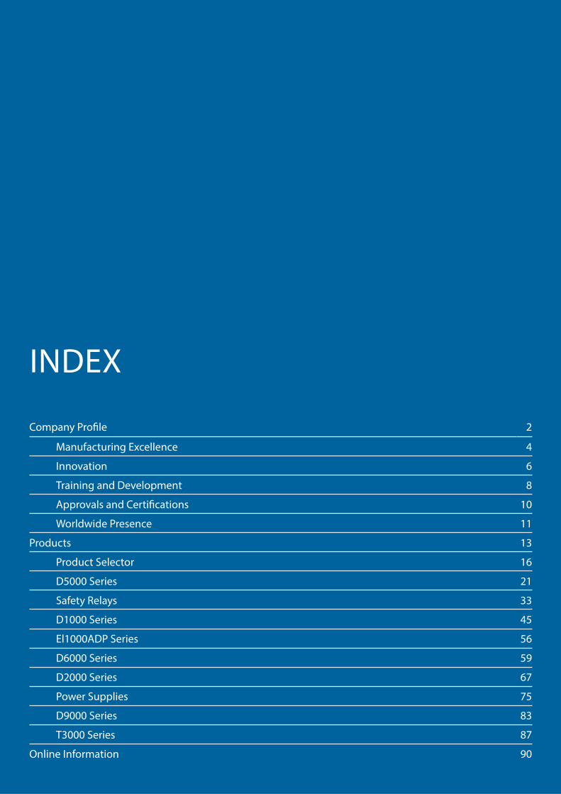
INDEX
Company Profi le 2
Manufacturing Excellence 4
Innovation 6
Training and Development 8
Approvals and Certifi cations 10
Worldwide Presence 11
Products 13
Product Selector 16
D5000 Series 21
Safety Relays 33
D1000 Series 45
El1000ADP Series 56
D6000 Series 59
D2000 Series 67
Power Supplies 75
D9000 Series 83
T3000 Series 87
Online Information 90

2
History
In 1970 Glisente Landrini founded Elcon Instruments, which has been acknowledged as an international leader in the design and manufacturing of Intrinsically Safe products and systems.Mr. Landrini started G.M. International to provide state of the art SIL rated products and services to support Intrinsically Safe applications in Oil & Gas, Petrochemical and Pharmaceutical Industries.The Company was founded in 1993, but the core Management experience remarkably exceeds over 40 years of qualifi ed activity in hazardous locations and industrial electronics.G.M. International’s products have been successfully installed in plants all over the world, including Europe, Russia, North America, Middle and Far East and China. G.M. International’s products interface all wiring between safe and hazardous areas and represent a fundamental, yet often under-estimated, layer of the instrumentation package. Intrinsically Safe isolators provide energy limitation to protect from risks of explosion while providing the highest grade of availability to guarantee both continuous operation and eff ectiveness of the safety layer.G.M. International has obtained SIL 3 FSM approval by TÜV according to IEC61508:2010 standard, and its products are certifi ed up to SIL3, off ering the greatest levels of functional safety for high integrity and critical applications.
Glisente LandriniPresident and Managing Director
COMPANYPROFILE

3
Headquarters in Italy
Goals and Values
• Designing and manufacturing Intrinsically Safe Instruments certifi ed up to SIL 3• Understanding, managing and reducing risks• Preventing accidents• Achieving 100% customer satisfaction• Demonstrating social responsibility and contributing to sustainable
development• Minimizing impact on environment and climate, and creating a safe and
healthy working environment • Being imaginative and stimulating new ideas• Being truthful and acting with integrity• Working together and sharing experience• Striving for simplifi cation and clarity, focusing on value-adding activities
Health Safety Environment
G.M. International conforms to latest HSE standards and to all local Health and Safety regulations and requirements with continuous and extensive personnel formation and hands-on training. Management is committed to the highest achievable HSE level throughout all stages of our activities and, it is our policy to protect our employees, customers, subcontractors and the community.Our objective is to reduce risks to the lowest level in order to reach a HSE goal of zero incidents, confi rmed by OHSAS 18001:2007 certifi cation.
Code of Ethics
All personell is highly qualifi ed, experienced and continuously trained.G.M. International employees adhere to a strict code of ethics approved by the Board of Directors.
4
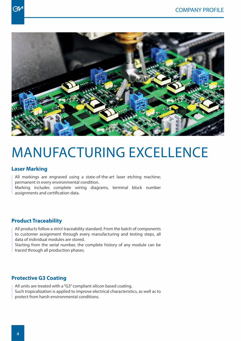
Laser Marking
All markings are engraved using a state-of-the-art laser etching machine; permanent in every environmental condition. Marking includes complete wiring diagrams, terminal block numberassignments and certifi cation data.
Product Traceability
All products follow a strict traceability standard. From the batch of components to customer assignment through every manufacturing and testing steps, all data of individual modules are stored.Starting from the serial number, the complete history of any module can be traced through all production phases.
Protective G3 Coating
All units are treated with a “G3” compliant silicon based coating.Such tropicalization is applied to improve electrical characteristics, as well as to protect from harsh environmental conditions.
MANUFACTURING EXCELLENCE
COMPANY PROFILE
A
5
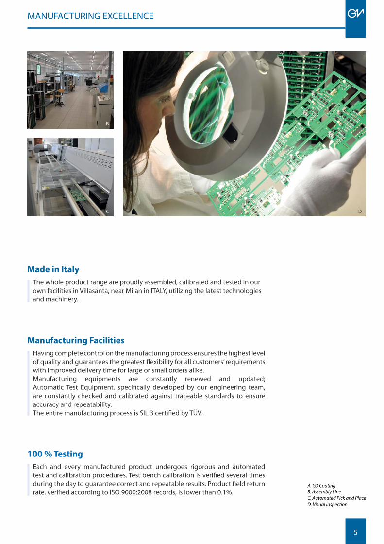
Manufacturing Facilities
Having complete control on the manufacturing process ensures the highest level of quality and guarantees the greatest fl exibility for all customers’ requirements with improved delivery time for large or small orders alike. Manufacturing equipments are constantly renewed and updated; Automatic Test Equipment, specifi cally developed by our engineering team, are constantly checked and calibrated against traceable standards to ensure accuracy and repeatability.The entire manufacturing process is SIL 3 certifi ed by TÜV.
MANUFACTURING EXCELLENCE
C D
B
A. G3 Coating B. Assembly LineC. Automated Pick and PlaceD. Visual Inspection
Made in Italy
The whole product range are proudly assembled, calibrated and tested in our own facilities in Villasanta, near Milan in ITALY, utilizing the latest technologies and machinery.
100 % Testing
Each and every manufactured product undergoes rigorous and automated test and calibration procedures. Test bench calibration is verifi ed several times during the day to guarantee correct and repeatable results. Product fi eld return rate, verifi ed according to ISO 9000:2008 records, is lower than 0.1%.
6
COMPANY PROFILE
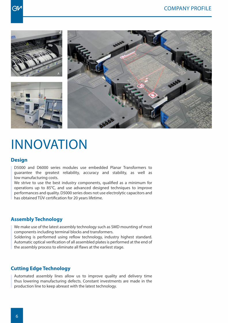
Design
D5000 and D6000 series modules use embedded Planar Transformers to guarantee the greatest reliability, accuracy and stability, as well as low manufacturing costs. We strive to use the best industry components, qualifi ed as a minimum for operations up to 85°C, and use advanced designed techniques to improve performances and quality. D5000 series does not use electrolytic capacitors and has obtained TÜV certifi cation for 20 years lifetime.
Assembly Technology
We make use of the latest assembly technology such as SMD mounting of most components including terminal blocks and transformers. Soldering is performed using refl ow technology, industry highest standard. Automatic optical verifi cation of all assembled plates is performed at the end of the assembly process to eliminate all fl aws at the earliest stage.
Cutting Edge Technology
Automated assembly lines allow us to improve quality and delivery time thus lowering manufacturing defects. Constant investments are made in the production line to keep abreast with the latest technology.
INNOVATION
C
A
B
7
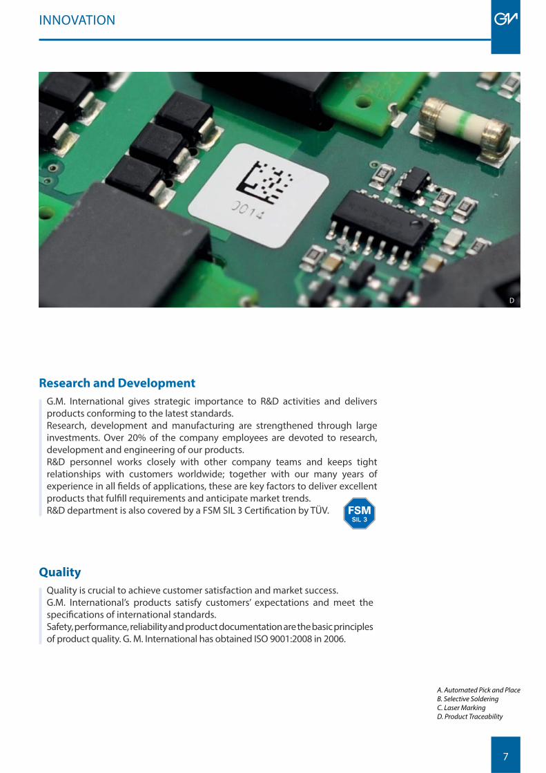
Research and Development
G.M. International gives strategic importance to R&D activities and delivers products conforming to the latest standards. Research, development and manufacturing are strengthened through large investments. Over 20% of the company employees are devoted to research, development and engineering of our products. R&D personnel works closely with other company teams and keeps tight relationships with customers worldwide; together with our many years of experience in all fi elds of applications, these are key factors to deliver excellent products that fulfi ll requirements and anticipate market trends. R&D department is also covered by a FSM SIL 3 Certifi cation by TÜV.
INNOVATION
Quality
Quality is crucial to achieve customer satisfaction and market success.G.M. International’s products satisfy customers’ expectations and meet the specifi cations of international standards. Safety, performance, reliability and product documentation are the basic principles of product quality. G. M. International has obtained ISO 9001:2008 in 2006.
A. Automated Pick and Place B. Selective SolderingC. Laser MarkingD. Product Traceability
D

8
Continuous Education
Continuous training and improvement of the staff ’s skills and capacities are key points to enhancing company performances and customer’s satisfaction. G.M. International off ers extra courses to raise our employees awareness of the company products and their use, in addition to mandatory training on HSE, Quality and manufacturing/testing practices.
Customer Support
G.M. International considers service as an integral part of customer’ s requirements and satisfaction. Among the services we off er:
• Cabinet assembly according to customer’s specifi cation and worldwide EX standards
• System Engineering• Custom solutions tailored to customer’s special requests• ISO 9000:2008 certifi ed post sales assistance service• Factory Acceptance Tests (FAT) on products and assembled cabinets that can
be staged in our facilities in Villasanta (MB) – Italy, at any of our subsidiaries or in the facilities of our worldwide system integrator partners
COMPANY PROFILE
TRAINING AND DEVELOPMENT
A

9
Customer Training
Special courses for engineering companies, end users and system integrators are also given both in-house and at customers sites on topics such as Intrinsic Safety (I.S.) and SIL levels of a Safety Instrumented System (SIS). Specifi cally, our SIL courses based on our SIL manual, have proven to be highly informative and have gained strong popularity. G.M. International is a course promoter of the TÜV Rheinland Functional Safety Program for Safety Instrumented Systems (SIS) trainings, see our website for available dates. The main objective is to provide engineers involved in safety instrumented systems with elementary and necessary knowledge of functional safety, based on IEC61508 and IEC61511.
TRAINING AND DEVELOMPMENT
Safety Instrumented Systems
This Manual is a pratical aid for the analysis, installation and maintenance of safety instrumented systems and associated components and will hopefully serve as a guide for understanding and implementing procedures into pratical applications.It represents an eff ort to share the results achieved in many years of research and experience in the fi eld, with anyone willing to approach Safety Related Systems.The manual is for the thousands of professionals employed in process industries who work with safety instrumented systems and who are expected to follow the appropriate industry standards.
A. Global Sales TeamB. Funcional Safety Engineer course held by Tino Vande Capelle, Functional Safety Services DirectorC. SIL Manual
C
B
10
CERTIFICATIONS
APPROVALS AND CERTIFICATIONS
IEC61508:2010 SIL Certifi cations
G.M. International off ers a wide range of products that have been proved to comply with the most severe quality and safety requirements.IEC61508 and IEC61511 standards represent a milestone in the progress of industry in the achievement of highest levels of safety through the entire instrumented system lifecycle. The majority of our products are SIL certifi ed as well as our design, manufacturing and administrative facilities (FSM); reports and certifi cates from TÜV and EXIDA are available for download from our website.
Intrinsically Safe Products
G.M. International’s products have been granted I.S. certifi cates from the most credited Notifi ed Bodies in the world. Certifi cates are available for ATEX (Europe), IECEx (International), USA and Canada, EAC-EX (Russian and Ukrainian), China, India, Japan, Brazil.All certifi cates are available for download from our website.
Maritime Type Approval
G.M. International off ers Type Approval Certifi cates for its line of Intrinsically Safe Isolators and Power Supplies for use in Maritime and Off shore applications.Certifi cates were issued by Det Norske Veritas and by Korean Register of Shipping.

11
We are there, wherever you need
G.M. International provides local pre and post sales support through its 7 direct subsidiaries and numerous agents and distributors in more than 55 countries.Our authorized sales network ensures a fast response wherever you are.Visit our website www.gmintsrl.com to fi nd an expert near you and take advantage of a global partnership with G.M. International.
WORLDWIDE
HOUSTON
WORLDWIDE PRESENCE
LYONMILAN
DUBAI
TEHERAN TOKYO
SHANGAI
SINGAPORE
Americas
• Argentina• Canada• Chile• Colombia• Mexico• Trinidad and Tobago• USA
Europe
• Austria• Estonia• France• Germany• Greece• Hungary• Ireland• Italy• Latvia• Lithuania• Norway• Poland• Romania• Russia• Spain• Sweden• The Netherlands• Turkey• Ukdraine• United Kingdom
Asia - Pacifi c
• Australia• Cambodia• China• India• Indonesia• Japan• Korea• Laos• Malaysia• Myanmar• New Zeldand• Philippines• Singapore• Thailand• Vietnam
Middle East
• Iran• Jordan• Kuwait• Libya• Oman• Qatar• Saudi Arabia• United Arab Emirates
Africa
• Algeria• Egypt• Morocco• Nigeria• Tunisia

12
13
D2000 SERIES
PRODUCTS
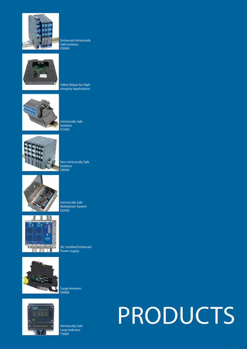
Non Intrinsically Safe IsolatorsD6000
SIL Certifi ed EnhancedPower Supply
Enhanced Intrinsically Safe IsolatorsD5000
Safety Relays for High Integrity Applications
Intrinsically Safe IsolatorsD1000
Intrinsically Safe Multiplexer SystemD2000
Surge ArrestersD9000
Intrinsically SafeLoop IndicatorT3000
14
Safety, performance and reliability: our products, our promises
From the latest instrinsically safe isolators to safety relays for high integrity applications, to enhanced power supply units and systems, here you can fi nd a complete overview of the product range of GM International. A product selector will help you fi nd the correct series or product for your systems. Detailed descriptions of our product series with general features, related accessories and technical selection tables to support you with the product that suits your application. Our products are certifi ed up to SIL 3, off ering the highest levels of functional safety for high integrity and critical applications.
Get inspired!Visit our website for further information: www.gmintsrl.com
PRODUCTSOVERVIEW

15
The following is a descriptive list of the icons that appear in this section:
PRODUCTS
ICONS
Intrinsically Safe Non Intrinsically Safe Features
Transmitter Switch or Proximity Safety Relay
MODBUS SIL 3 Level according to IEC 61508, IEC 61511
I/P Converter Proximity ElectrovalveSIL 2 Level according to IEC 61508, IEC 61511
Current or Voltage Signal
Magnetic Pickup or Proximity LED Pulse Test compatible
Current SignalLoad CellStrain Gauge Fire and Gas System Diagnostics available
Thermocouple or RTD 4-wires Vibration Sensor Visual Alarm
MODBUS
MODBUS RTU available
Thermocouple or RTD 3-wires
RS-485RS-422 Serial Comunication
Protocol Audible AlarmTB Only for Termination
Board
Thermocouple or Voltage Signal
D2010MD2030M For connection to fi eld
units D2010M, D2030MIsolated AC/DCPower Supply Confi gurable via PC
RTD 3-wiresIsolated AC/DCPower Supply
Electrovalve
LED
Switch-over Relay
16
PRODUCT SELECTOR
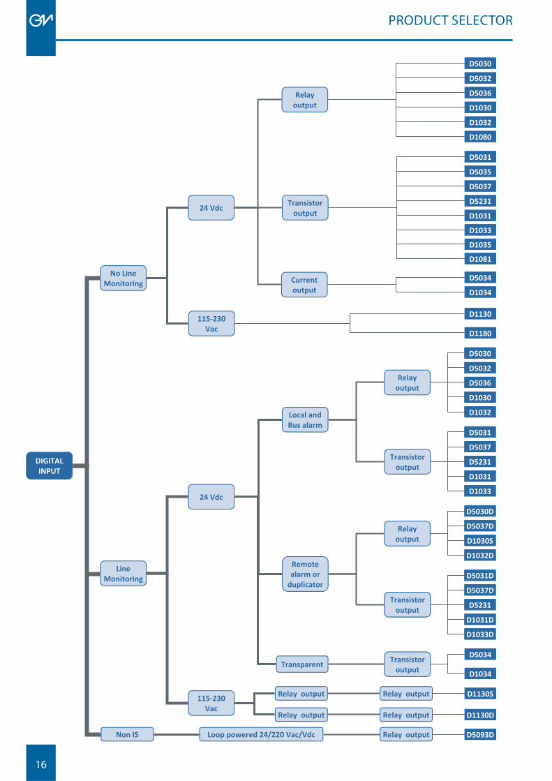
DIGITAL INPUT
No Line Monitoring
24 Vdc
115-230 Vac
Line Monitoring
24 Vdc
115-230 Vac
Local and Bus alarm
Remote alarm or
duplicator
Transparent
Relay output
Relay output
Transistor output
Transistor output
Relay output
Relay output
Relay output
Relay output
Relay output
Loop powered 24/220 Vac/Vdc Non IS
Transistor output
Transistoroutput
D5030
D5032
D5036
D1030
D1032
D1080
D5031
D5035
D5037
D5231
D1031
D1033
D1035
D1081
D5034
D1034
D1130
D1180
D5030
D5032
D5036
D1030
D1032
D5031
D5037
D5231
D1031
D1033
D5030D
D5037D
D1030S
D1032D
D5031D
D5037D
D5231
D1031D
D1033D
D5034
D1034
D1130S
D1130D
D5093D
Relayoutput
Transistoroutput
Currentoutput
17
PRODUCT SELECTOR
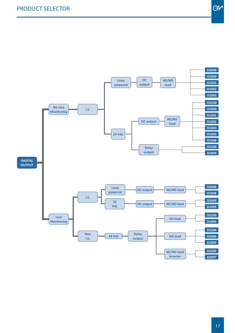
Line Monitoring
D5295
D5048
D1048
D5049
D1049
D5293
D1093
D5294
D5096
I.S.
Non I.S.
Loop powered
24 Vdc
DC output
DC output
NE/ND load
NE/ND load
Relay output
NE load
ND load
NE/ND load inverter
24 Vdc
D1093
D5097
No LineMonitoring I.S.
24 Vdc
Relay output
D5040
D1040
D1041
D1042
D1043
D5240
D1040
D1041
D1042
D1043
D1045
D1046
D5244
D1044
DC output NE/ND load
DC output
Loop powered
NE/ND load
DIGITAL OUTPUT
18
PRODUCT SELECTOR
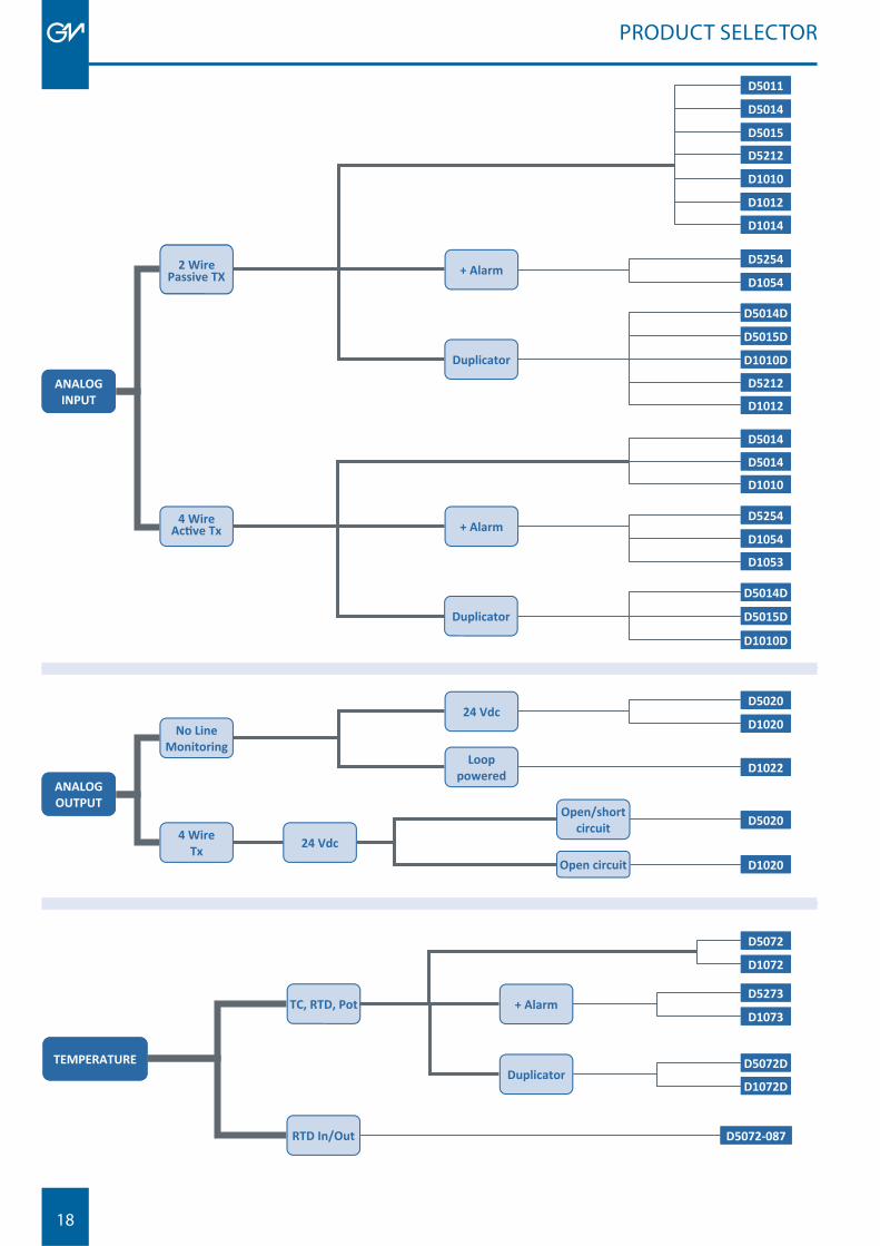
ANALOG INPUT
+ Alarm
D5011
D5014
D5212
D1010
D1012
D1014
D5254
D1054
D5014D
4 Wire
x + Alarm
D5014
D1010
D5254
D1054
D5014D
D5015D
D1053
D5015
D1010D
D5212
D1012
D5015D
D1010D
Duplicator
Duplicator
D5014
ANALOG OUTPUT
No Line Monitoring
24 Vdc
Loop powered
4 Wire Tx
Open/short circuit
Open circuit 24 Vdc
D5020
D1020
D5020
D1020
D1022
TEMPERATURE
RTD In/Out D5072-087
TC, RTD, Pot + Alarm
D5072
D1072
D5273
D1073
Duplicator
D5072D
D1072D
19
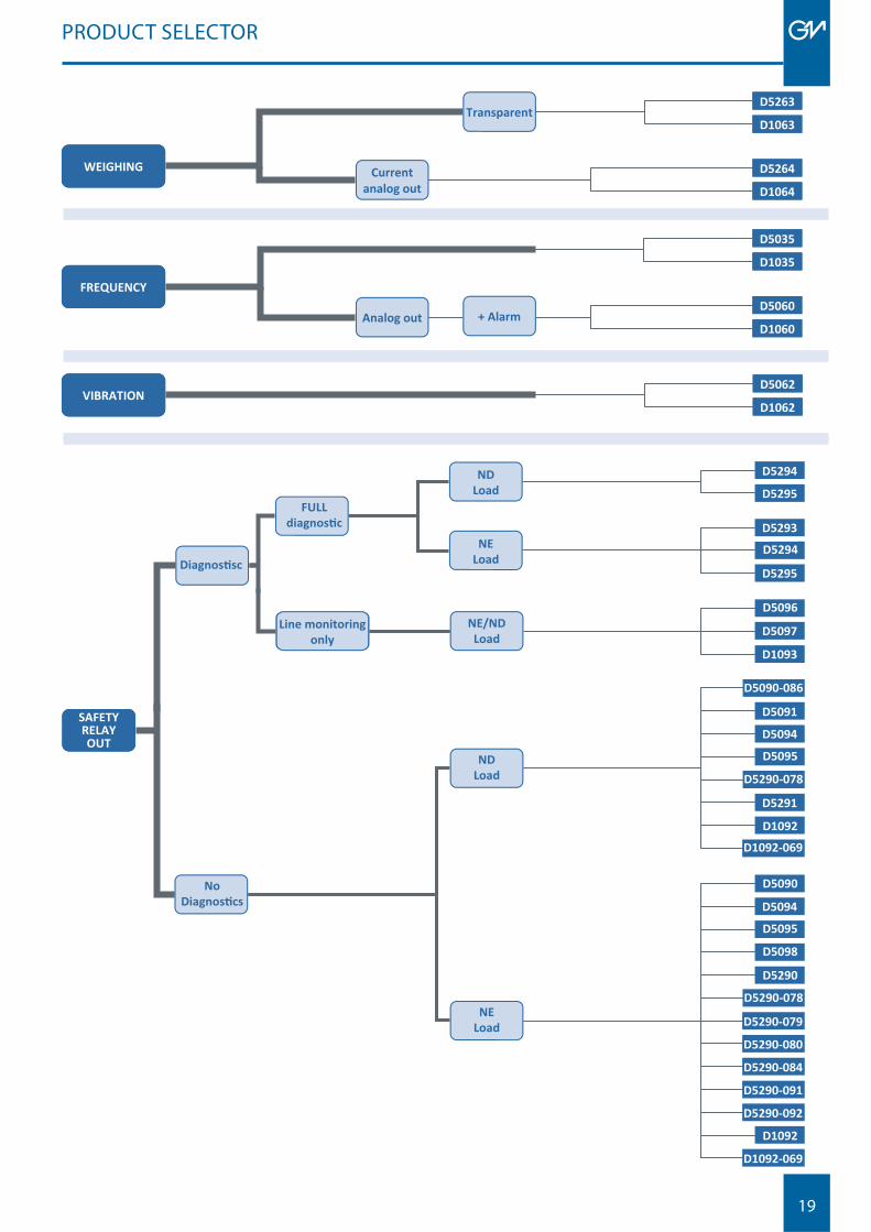
PRODUCT SELECTOR
WEIGHING Current analog out
Transparent D5263
D1063
D5264
D1064
FREQUENCY
Analog out
D5035
D1035
D5060
D1060 + Alarm
VIBRATIOND5062
D1062
FULL
Line monitoring
only
SAFETYRELAYOUT
D5090
NELoad
D5290
D5290-078
D5290-079
D5290-080
D5290-084
D1092
D1092-069
D5094
D5095
D5098
D5290-092
D5290-091
NE/NDLoad
D1093
D5096
D5097
ND
LoadD5294
D5295
D5295
D5294
D5293NE
Load
NDLoad
D5091
D5291
D5094
D5290-078
D5095
D5090-086
D1092D1092-069
No

20
21
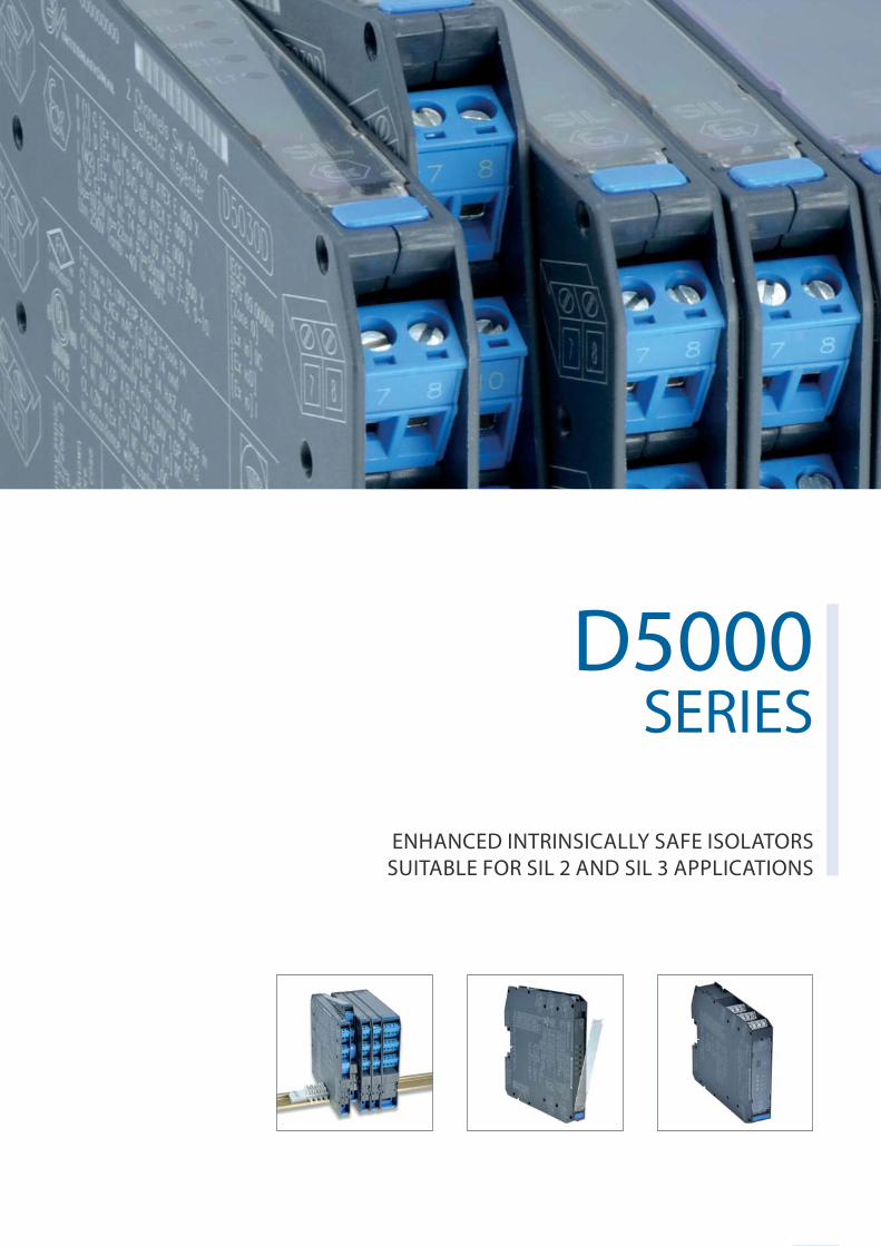
D5000SERIES
ENHANCED INTRINSICALLY SAFE ISOLATORSSUITABLE FOR SIL 2 AND SIL 3 APPLICATIONS
D5000 SERIES
22
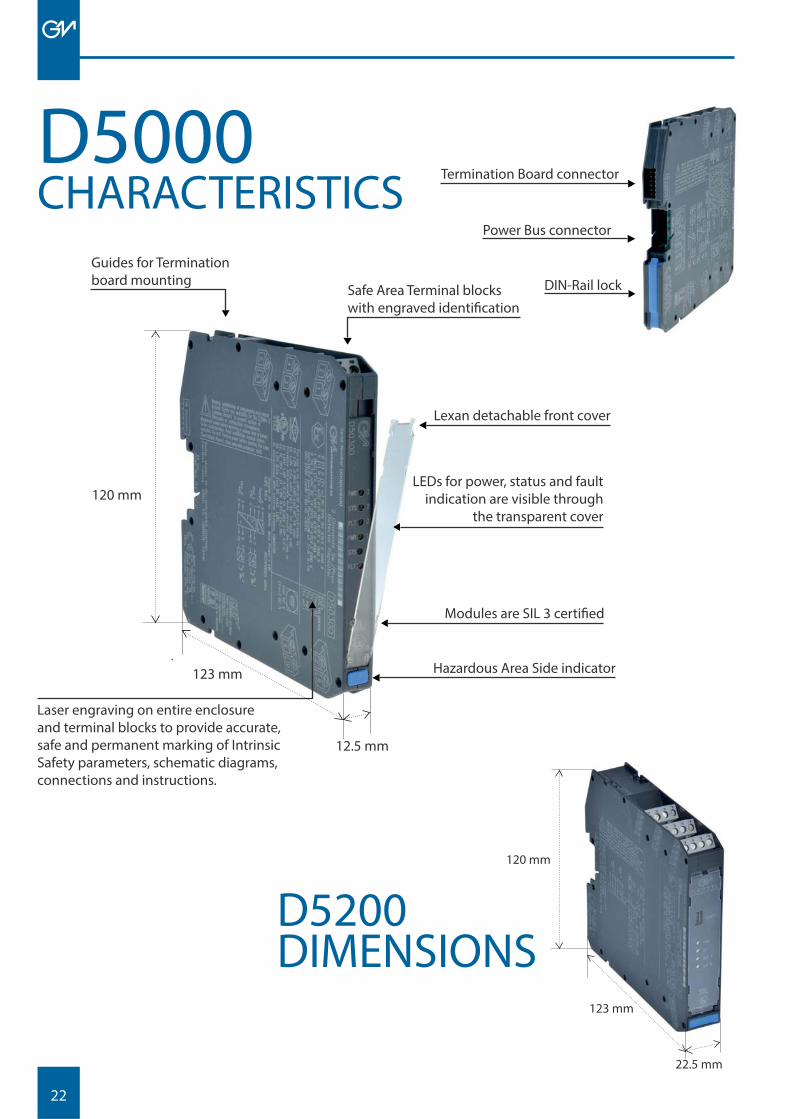
DIN-Rail lock
Power Bus connector
Termination Board connector
CHARACTERISTICSD5000
Guides for Termination board mounting
Safe Area Terminal blocks with engraved identifi cation
Lexan detachable front cover
LEDs for power, status and fault indication are visible through
the transparent cover
Modules are SIL 3 certifi ed
Hazardous Area Side indicator
Laser engraving on entire enclosure and terminal blocks to provide accurate, safe and permanent marking of Intrinsic Safety parameters, schematic diagrams, connections and instructions.
120 mm
123 mm
12.5 mm
120 mm
22.5 mm
123 mm
D5200DIMENSIONS
23
D5000 SERIES
High Performance
• High signal transfer accuracy and repeatability• Advanced circuitry provides very low heat dissipation,
ensuring modules run cool despite their high density and functionality
• SMD manufacturing for a long, reliable life• Complete absence of electrolytic capacitors ensures
minimum 20 years lifetime
Wide Functionality
• Wide range of digital and analog I/O• SIL 3 Safety Relay contacts rated for 4 A or 10 A for
direct switching of high loads• Three port galvanic isolation to eliminate noise,
ground loop problems and to provide Intrinsic Safety without a high integrity safety earth connection
• Line fault alarm detects open or short circuit of fi eld cables• Optional power bus DIN-Rail connector• Standard Termination Board with custom connectors
for integration into customized Boards• EMC Compatibility to EN61000-6-2, EN61000-6-4,
EN61326-1, EN61326-3-1 for safety system
General Features
• More than 25 modules suitable for SIL 3 applications according to IEC61508, IEC61511
• Independent power supply circuits for each channel on most modules
• Dual channel units are equivalent to two single units because of the absence of common circuitry on most modules
• Single channel versions available when required, to provide single loop integrity
• Confi guration components are easily accessed by removing the side cover or via connector front panel
• DIP switch confi gurability for easy fi eld setup• LED indication for power, signal status and line
fault conditions• Modules accept DC power supply over a wide
range for 24 Vdc (18-30 Vdc) applications• Wide operating temp. range: -40 to +60/+70 °C• Installation in Zone 2 / Division 2• Certifi ed for Off shore and Maritime applications
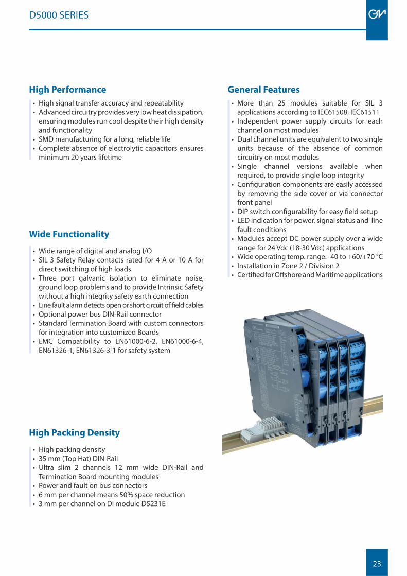
High Packing Density
• High packing density• 35 mm (Top Hat) DIN-Rail• Ultra slim 2 channels 12 mm wide DIN-Rail and
Termination Board mounting modules• Power and fault on bus connectors• 6 mm per channel means 50% space reduction• 3 mm per channel on DI module D5231E
24
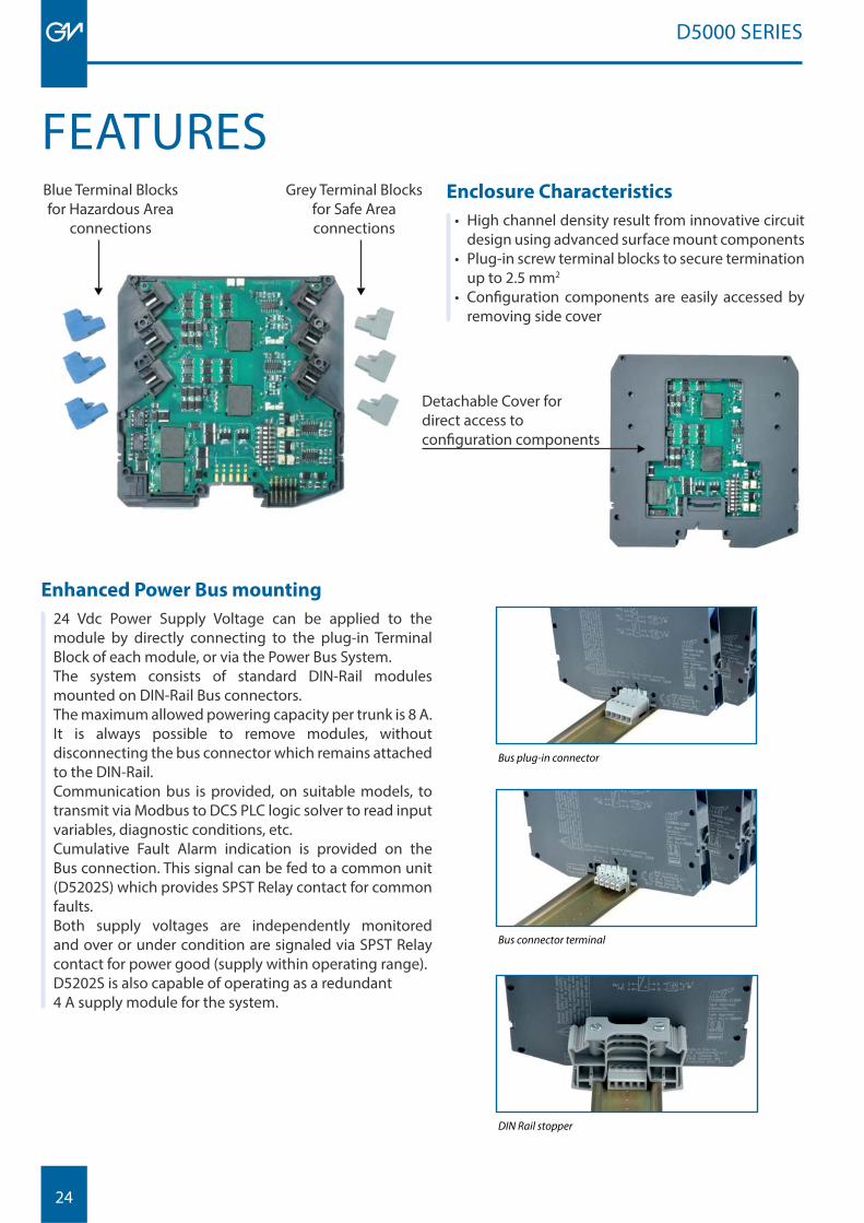
Enclosure Characteristics
• High channel density result from innovative circuit design using advanced surface mount components
• Plug-in screw terminal blocks to secure termination up to 2.5 mm2
• Confi guration components are easily accessed byremoving side cover
Blue Terminal Blocksfor Hazardous Area
connections
Grey Terminal Blocks for Safe Area connections
Detachable Cover for direct access to confi guration components
Enhanced Power Bus mounting
24 Vdc Power Supply Voltage can be applied to the module by directly connecting to the plug-in Terminal Block of each module, or via the Power Bus System.The system consists of standard DIN-Rail modules mounted on DIN-Rail Bus connectors. The maximum allowed powering capacity per trunk is 8 A. It is always possible to remove modules, without disconnecting the bus connector which remains attached to the DIN-Rail.Communication bus is provided, on suitable models, to transmit via Modbus to DCS PLC logic solver to read input variables, diagnostic conditions, etc. Cumulative Fault Alarm indication is provided on the Bus connection. This signal can be fed to a common unit (D5202S) which provides SPST Relay contact for common faults. Both supply voltages are independently monitored and over or under condition are signaled via SPST Relay contact for power good (supply within operating range).D5202S is also capable of operating as a redundant 4 A supply module for the system.
FEATURES
D5000 SERIES
Bus plug-in connector
Bus connector terminal
DIN Rail stopper
25
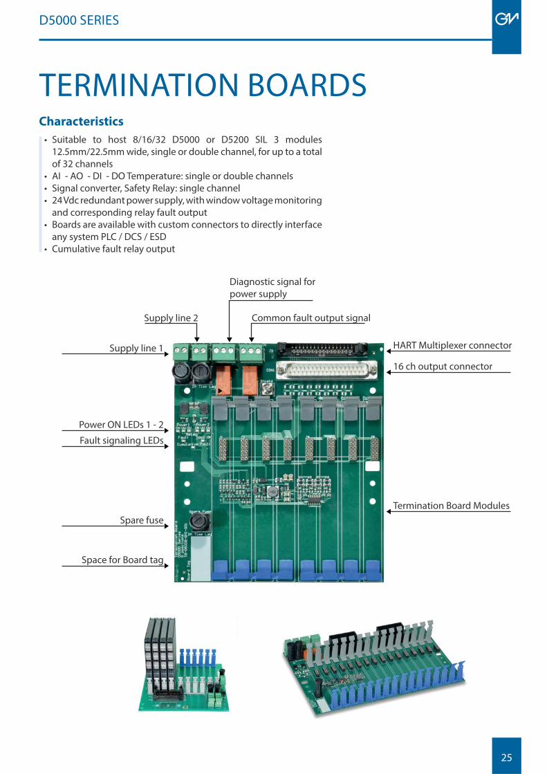
Characteristics
• Suitable to host 8/16/32 D5000 or D5200 SIL 3 modules 12.5mm/22.5mm wide, single or double channel, for up to a total of 32 channels
• AI - AO - DI - DO Temperature: single or double channels• Signal converter, Safety Relay: single channel• 24 Vdc redundant power supply, with window voltage monitoring
and corresponding relay fault output• Boards are available with custom connectors to directly interface
any system PLC / DCS / ESD• Cumulative fault relay output
TERMINATION BOARDS
HART Multiplexer connector
16 ch output connector
Termination Board Modules
Space for Board tag
Spare fuse
Fault signaling LEDs
Power ON LEDs 1 - 2
Supply line 1
Common fault output signal
Diagnostic signal for power supply
Supply line 2
D5000 SERIES
26
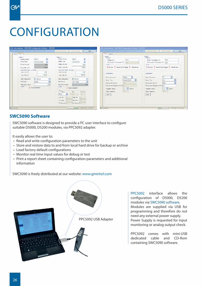
SWC5090 Software
SWC5090 software is designed to provide a PC user interface to confi gure suitable D5000, D5200 modules, via PPC5092 adapter.
It easily allows the user to:• Read and write confi guration parameters to the unit• Store and restore data to and from local hard drive for backup or archive• Load factory default confi gurations• Monitor real time Input values for debug or test• Print a report sheet containing confi guration parameters and additional
information
SWC5090 is freely distributed at our website: www.gmintsrl.com
CONFIGURATION
PPC5092 USB Adapter
PPC5092 interface allows the confi guration of D5000, D5200 modules via SWC5090 software. Modules are supplied via USB for programming and therefore do not need any external power supply.Power Supply is requested for input monitoring or analog output check.
PPC5092 comes with mini-USB dedicated cable and CD-Rom containing SWC5090 software.
D5000 SERIES
27
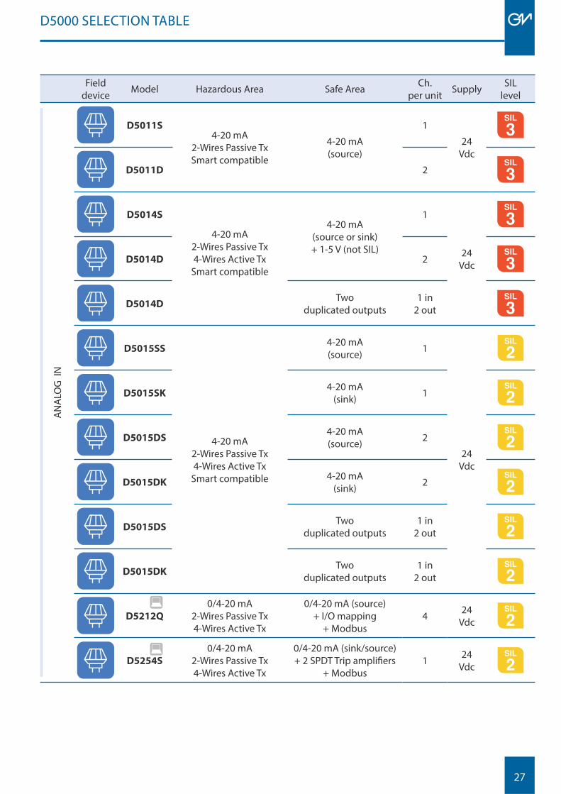
D5000 SELECTION TABLE
Fielddevice Model Hazardous Area Safe Area Ch.
per unit Supply SIL level
AN
ALO
G I
N
D5011S4-20 mA
2-Wires Passive TxSmart compatible
4-20 mA(source)
1
24Vdc
MODBUS
D5011D 2 MODBUS
D5014S
4-20 mA2-Wires Passive Tx4-Wires Active Tx
Smart compatible
4-20 mA(source or sink)+ 1-5 V (not SIL)
1
24 Vdc
MODBUS
D5014D 2 MODBUS
D5014DTwo
duplicated outputs1 in
2 outMODBUS
D5015SS
4-20 mA2-Wires Passive Tx4-Wires Active Tx
Smart compatible
4-20 mA(source) 1
24 Vdc
D5015SK4-20 mA
(sink) 1
D5015DS4-20 mA(source) 2
D5015DK4-20 mA
(sink) 2
D5015DSTwo
duplicated outputs1 in
2 out
D5015DKTwo
duplicated outputs1 in
2 out
D5212Q
0/4-20 mA2-Wires Passive Tx4-Wires Active Tx
0/4-20 mA (source)+ I/O mapping
+ Modbus4 24
Vdc
D5254S
0/4-20 mA2-Wires Passive Tx4-Wires Active Tx
0/4-20 mA (sink/source)+ 2 SPDT Trip amplifi ers
+ Modbus1 24
Vdc
28
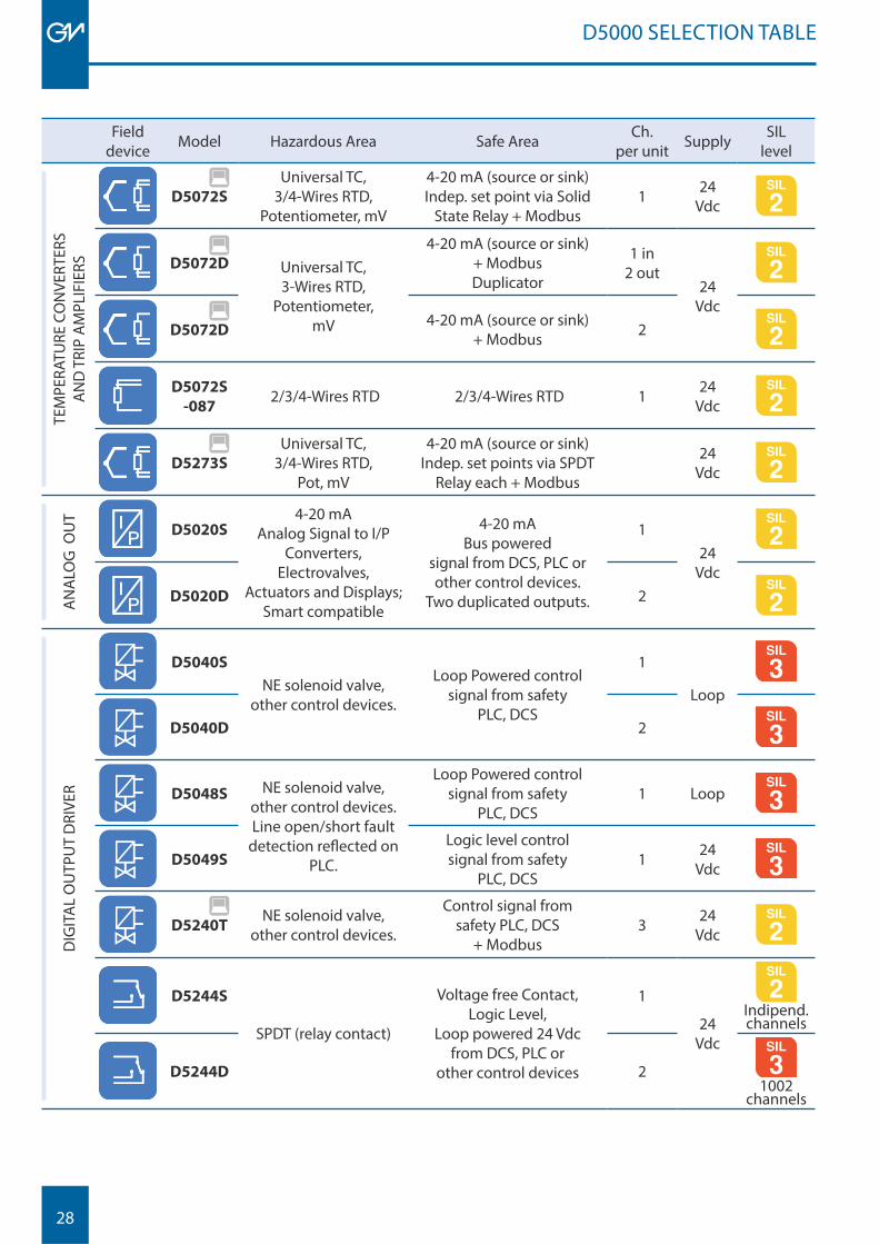
D5000 SELECTION TABLE
Fielddevice Model Hazardous Area Safe Area Ch.
per unit Supply SIL level
TEM
PERA
TURE
CO
NVE
RTER
SA
ND
TRI
P A
MPL
IFIE
RS
D5072S
Universal TC, 3/4-Wires RTD,
Potentiometer, mV
4-20 mA (source or sink) Indep. set point via Solid
State Relay + Modbus1 24
Vdc
D5072D Universal TC, 3-Wires RTD,
Potentiometer, mV
4-20 mA (source or sink) + ModbusDuplicator
1 in2 out
24Vdc
D5072D4-20 mA (source or sink)
+ Modbus 2
D5072S
-087 2/3/4-Wires RTD 2/3/4-Wires RTD 1 24
Vdc
D5273S
Universal TC, 3/4-Wires RTD,
Pot, mV
4-20 mA (source or sink) Indep. set points via SPDT
Relay each + Modbus 24
Vdc
AN
ALO
G O
UT
D5020S4-20 mA
Analog Signal to I/PConverters,
Electrovalves,Actuators and Displays;
Smart compatible
4-20 mABus powered
signal from DCS, PLC or other control devices.
Two duplicated outputs.
124
VdcD5020D 2
DIG
ITA
L O
UTP
UT
DRI
VER
D5040S
NE solenoid valve,other control devices.
Loop Powered control signal from safety
PLC, DCS
1
Loop
MODBUS
D5040D 2 MODBUS
D5048S NE solenoid valve,other control devices.Line open/short fault
detection refl ected on PLC.
Loop Powered control signal from safety
PLC, DCS1 Loop MODBUS
D5049S
Logic level control signal from safety
PLC, DCS1 24
Vdc MODBUS
D5240TNE solenoid valve,
other control devices.
Control signal from safety PLC, DCS
+ Modbus3 24
Vdc
D5244S
SPDT (relay contact)
Voltage free Contact,Logic Level,
Loop powered 24 Vdcfrom DCS, PLC or
other control devices
1
24Vdc
Indipend.channels
D5244D 2MODBUS
1002channels
29
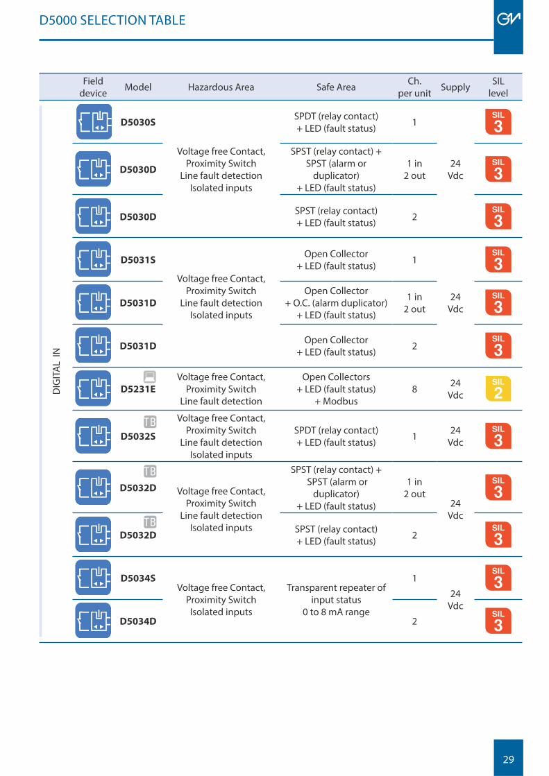
Fielddevice Model Hazardous Area Safe Area Ch.
per unit Supply SIL level
DIG
ITA
L IN
D5030S
Voltage free Contact,Proximity Switch
Line fault detectionIsolated inputs
SPDT (relay contact)+ LED (fault status) 1
24Vdc
MODBUS
D5030D
SPST (relay contact) +SPST (alarm or
duplicator)+ LED (fault status)
1 in2 out
MODBUS
D5030DSPST (relay contact)+ LED (fault status) 2 MODBUS
D5031S
Voltage free Contact,Proximity Switch
Line fault detectionIsolated inputs
Open Collector + LED (fault status) 1
24Vdc
MODBUS
D5031D
Open Collector+ O.C. (alarm duplicator)
+ LED (fault status)
1 in 2 out
MODBUS
D5031DOpen Collector
+ LED (fault status) 2 MODBUS
D5231E
Voltage free Contact,Proximity Switch
Line fault detection
Open Collectors+ LED (fault status)
+ Modbus8 24
Vdc
D5032S
Voltage free Contact,Proximity Switch
Line fault detectionIsolated inputs
SPDT (relay contact)+ LED (fault status) 1 24
VdcMODBUS
D5032D Voltage free Contact,Proximity Switch
Line fault detectionIsolated inputs
SPST (relay contact) + SPST (alarm or
duplicator)+ LED (fault status)
1 in 2 out
24 Vdc
MODBUS
D5032DSPST (relay contact)+ LED (fault status) 2 MODBUS
D5034SVoltage free Contact,
Proximity SwitchIsolated inputs
Transparent repeater ofinput status
0 to 8 mA range
1
24 Vdc
MODBUS
D5034D 2 MODBUS
D5000 SELECTION TABLE
TB
TB
TB
30
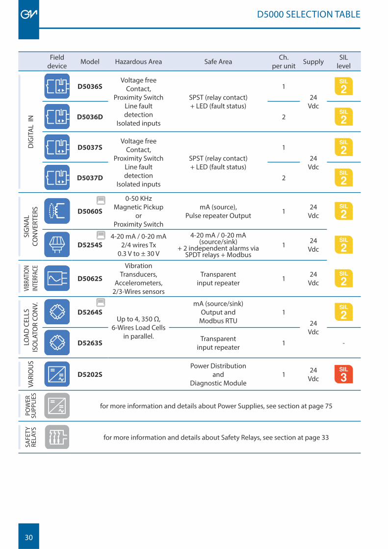
D5000 SELECTION TABLE
Fielddevice Model Hazardous Area Safe Area Ch.
per unit Supply SIL level
DIG
ITA
L IN
D5036SVoltage free
Contact,Proximity Switch
Line fault detection
Isolated inputs
SPST (relay contact)+ LED (fault status)
1
24 Vdc
D5036D 2
D5037SVoltage free
Contact,Proximity Switch
Line fault detection
Isolated inputs
SPST (relay contact)+ LED (fault status)
1
24 Vdc
D5037D 2
SIG
NA
L CO
NVE
RTER
S
D5060S
0-50 KHz Magnetic Pickup
or Proximity Switch
mA (source),Pulse repeater Output 1 24
Vdc
D5254S
4-20 mA / 0-20 mA2/4 wires Tx
0.3 V to ± 30 V
4-20 mA / 0-20 mA(source/sink)
+ 2 independent alarms via SPDT relays + Modbus
1 24 Vdc
VIBR
ATIO
NIN
TERF
ACE
D5062S
Vibration Transducers,
Accelerometers,2/3-Wires sensors
Transparent input repeater 1 24
Vdc
LOA
D C
ELLS
ISO
LATO
R CO
NV.
D5264SUp to 4, 350 Ω,
6-Wires Load Cellsin parallel.
mA (source/sink)Output and
Modbus RTU1
24Vdc
D5263STransparent
input repeater 1 -
VARI
OU
S
D5202S
Power Distribution and
Diagnostic Module1 24
VdcMODBUS
POW
ER
SUPP
LIES
for more information and details about Power Supplies, see section at page 75
SAFE
TY
RELA
YS
for more information and details about Safety Relays, see section at page 33
31
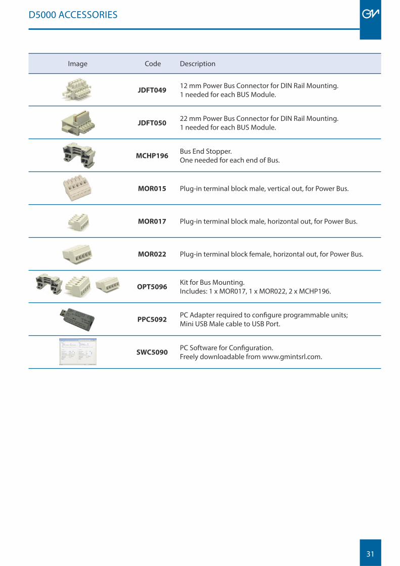
Image Code Description
JDFT04912 mm Power Bus Connector for DIN Rail Mounting.1 needed for each BUS Module.
JDFT05022 mm Power Bus Connector for DIN Rail Mounting.1 needed for each BUS Module.
MCHP196Bus End Stopper.One needed for each end of Bus.
MOR015 Plug-in terminal block male, vertical out, for Power Bus.
MOR017 Plug-in terminal block male, horizontal out, for Power Bus.
MOR022 Plug-in terminal block female, horizontal out, for Power Bus.
OPT5096Kit for Bus Mounting. Includes: 1 x MOR017, 1 x MOR022, 2 x MCHP196.
PPC5092PC Adapter required to confi gure programmable units; Mini USB Male cable to USB Port.
SWC5090PC Software for Confi guration.Freely downloadable from www.gmintsrl.com.
D5000 ACCESSORIES

32
33
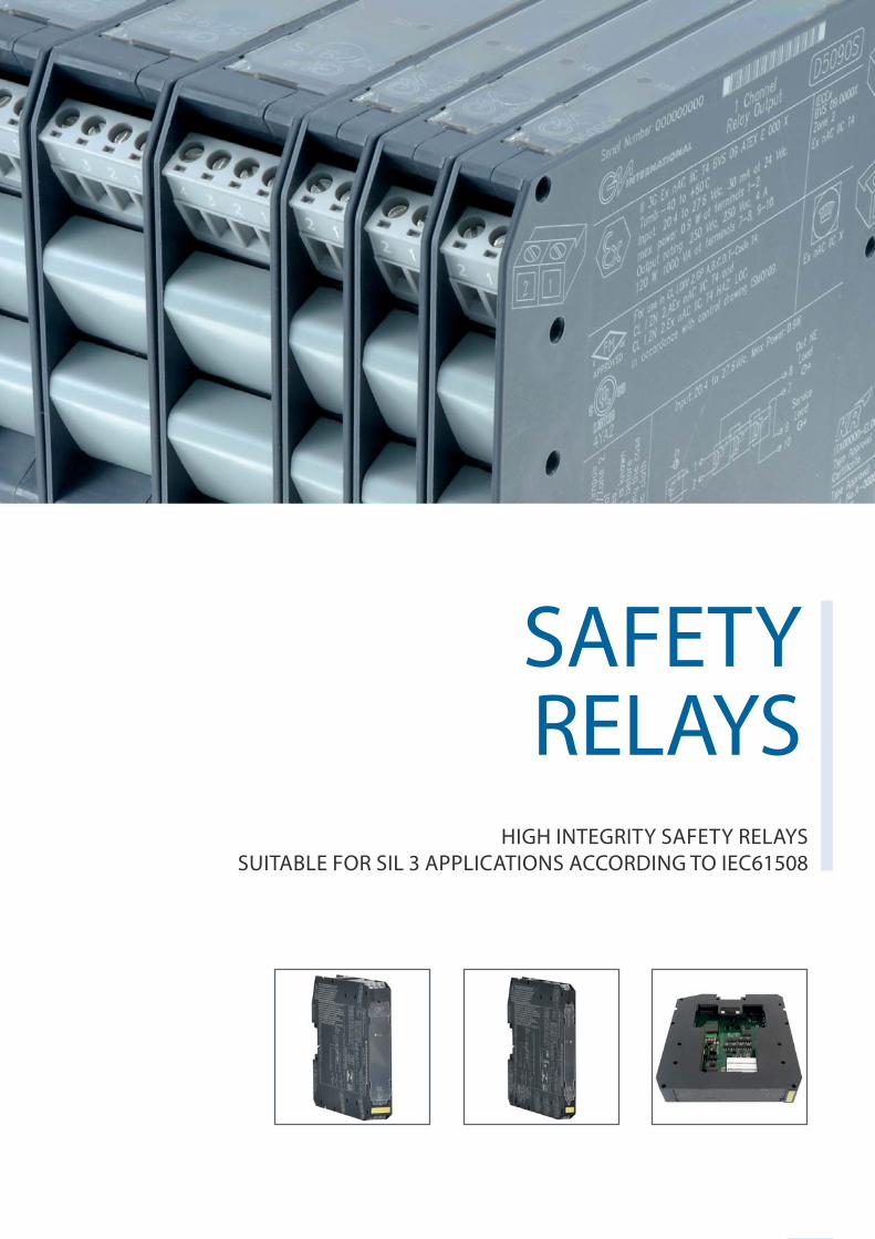
SAFETY RELAYS
HIGH INTEGRITY SAFETY RELAYSSUITABLE FOR SIL 3 APPLICATIONS ACCORDING TO IEC61508
34
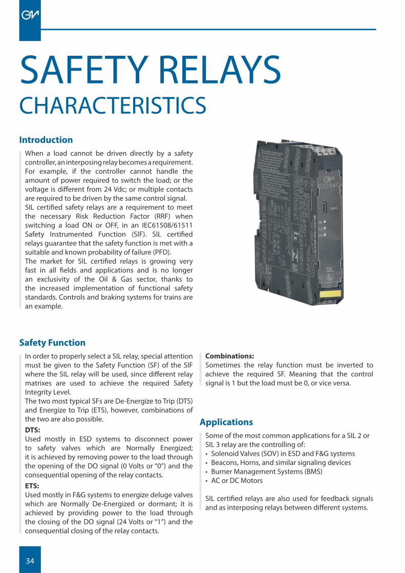
Introduction
When a load cannot be driven directly by a safety controller, an interposing relay becomes a requirement. For example, if the controller cannot handle the amount of power required to switch the load; or the voltage is diff erent from 24 Vdc; or multiple contacts are required to be driven by the same control signal.SIL certifi ed safety relays are a requirement to meet the necessary Risk Reduction Factor (RRF) when switching a load ON or OFF, in an IEC61508/61511 Safety Instrumented Function (SIF). SIL certifi ed relays guarantee that the safety function is met with a suitable and known probability of failure (PFD).The market for SIL certifi ed relays is growing very fast in all fi elds and applications and is no longer an exclusivity of the Oil & Gas sector, thanks to the increased implementation of functional safety standards. Controls and braking systems for trains are an example.
Applications
Some of the most common applications for a SIL 2 or SIL 3 relay are the controlling of:• Solenoid Valves (SOV) in ESD and F&G systems• Beacons, Horns, and similar signaling devices• Burner Management Systems (BMS)• AC or DC Motors
SIL certifi ed relays are also used for feedback signals and as interposing relays between diff erent systems.
Combinations:
Sometimes the relay function must be inverted to achieve the required SF. Meaning that the control signal is 1 but the load must be 0, or vice versa.
Safety Function
In order to properly select a SIL relay, special attention must be given to the Safety Function (SF) of the SIF where the SIL relay will be used, since diff erent relay matrixes are used to achieve the required Safety Integrity Level.The two most typical SFs are De-Energize to Trip (DTS) and Energize to Trip (ETS), however, combinations of the two are also possible.DTS:
Used mostly in ESD systems to disconnect power to safety valves which are Normally Energized; it is achieved by removing power to the load through the opening of the DO signal (0 Volts or “0”) and the consequential opening of the relay contacts.ETS:
Used mostly in F&G systems to energize deluge valves which are Normally De-Energized or dormant; it is achieved by providing power to the load through the closing of the DO signal (24 Volts or “1”) and the consequential closing of the relay contacts.
CHARACTERISTICSSAFETY RELAYS
35
SAFETY RELAYS
Relay Functions
There are four kinds of SIL relay functions defi ned by the status of the relay coil and the relay contacts in normal working conditions; not during a Safety Demand (SD).1. Energized Coil (1) - Closed C ontacts (1):
Load Normally Energized; DTS Safety Function.2. De-Energized Coil (0) - Open Contacts (0):
Load Normally De-Energized; ETS Safety Function.3. Energized Coil (1) - Open Contacts (0):
Load Normally De-Energized; DTS Safety Function.4. De-Energized Coil (0) - Closed Contacts (1):
Load Normally Energized; ETS Safety Function.
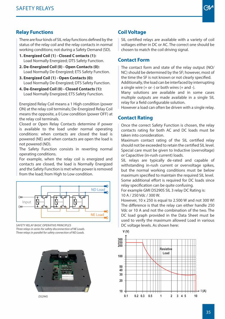
Energized Relay Coil means a 1 High condition (power ON) at the relay coil terminals; De-Energized Relay Coil means the opposite, a 0 Low condition (power OFF) at the relay coil terminals.Closed or Open Relay Contacts determine if power is available to the load under normal operating conditions: when contacts are closed the load is powered (NE) and when contacts are open the load is not powered (ND).The Safety Function consists in reverting normal operating conditions.For example, when the relay coil is energized and contacts are closed, the load is Normally Energized and the Safety Function is met when power is removed from the load; from High to Low condition.
ND Load
NE Load
Input
SAFETY RELAY BASIC OPERATIVE PRINCIPLESThree relays in series for safety disconnection of NE Loads.Three relays in parallel for safety connection of ND Loads.
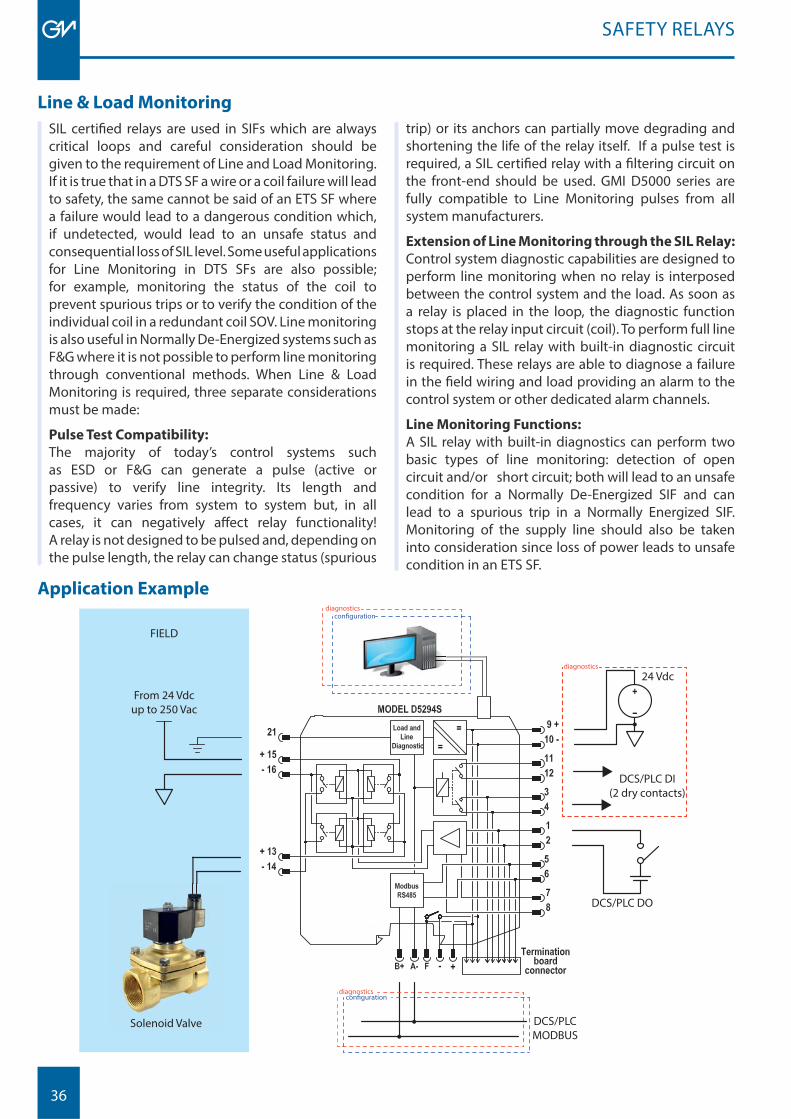
Contact Rating
Once the correct Safety Function is chosen, the relay contacts rating for both AC and DC loads must be taken into consideration.Maximum contact rating of the SIL certifi ed relay should not be exceeded to retain the certifi ed SIL level. Special care must be given to Inductive (overvoltage) or Capacitive (in-rush current) loads.SIL relays are typically de-rated and capable of withstanding in-rush current or overvoltage spikes, but the normal working conditions must be below maximum specifi ed to maintain the required SIL level.Some additional eff ort is required for DC loads since relay specifi cation can be quite confusing.For example GMI D5290S SIL 3 relay DC Rating is:10 A / 250 Vdc / 300 W.However, 10 x 250 is equal to 2.500 W and not 300 W! The diff erence is that the relay can either handle 250 Vdc or 10 A and not the combination of the two. The DC load graph provided in the Data Sheet must be used to verify the maximum allowed Load in various DC voltage levels. As shown here:
Contact Form
The contact form and state of the relay output (NO/NC) should be determined by the SF; however, most of the time the SF is not known or not clearly specifi ed.Additionally, the load can be interfaced by interrupting a single wire (+ or -) or both wires (+ and -).Many solutions are available and in some cases multiple outputs are made available in a single SIL relay for a fi eld confi gurable solution.However a load can often be driven with a single relay.
Coil Voltage
SIL certifi ed relays are available with a variety of coil voltages either in DC or AC. The correct one should be chosen to match the coil driving signal.
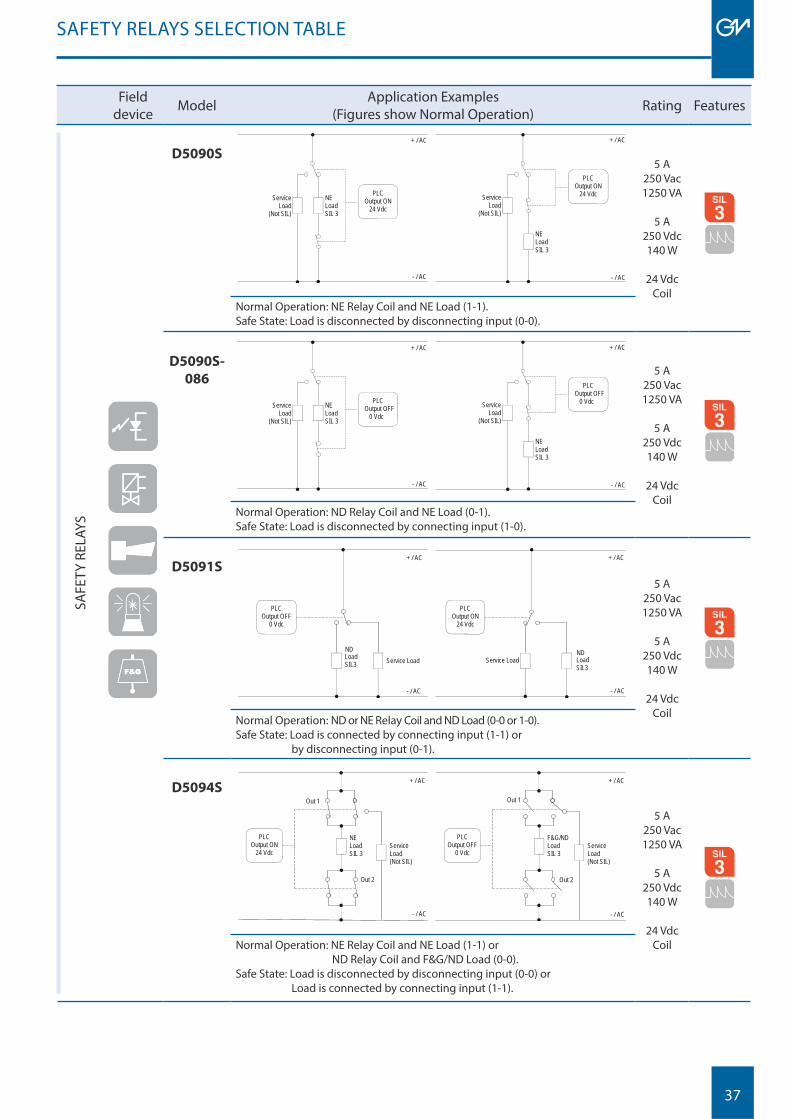
D5294S
36
SAFETY RELAYS
diagnosticsconfiguration
diagnostics
DCS/PLC DI(2 dry contacts)
24 Vdc
DCS/PLC DO
DCS/PLCMODBUS
diagnosticsconfiguration
Solenoid Valve
From 24 Vdcup to 250 Vac
FIELD
Line & Load Monitoring
SIL certifi ed relays are used in SIFs which are always critical loops and careful consideration should be given to the requirement of Line and Load Monitoring. If it is true that in a DTS SF a wire or a coil failure will lead to safety, the same cannot be said of an ETS SF where a failure would lead to a dangerous condition which, if undetected, would lead to an unsafe status and consequential loss of SIL level. Some useful applications for Line Monitoring in DTS SFs are also possible; for example, monitoring the status of the coil to prevent spurious trips or to verify the condition of the individual coil in a redundant coil SOV. Line monitoring is also useful in Normally De-Energized systems such as F&G where it is not possible to perform line monitoring through conventional methods. When Line & Load Monitoring is required, three separate considerations must be made:
Pulse Test Compatibility: The majority of today’s control systems such as ESD or F&G can generate a pulse (active or passive) to verify line integrity. Its length and frequency varies from system to system but, in all cases, it can negatively aff ect relay functionality! A relay is not designed to be pulsed and, depending on the pulse length, the relay can change status (spurious
Application Example
trip) or its anchors can partially move degrading and shortening the life of the relay itself. If a pulse test is required, a SIL certifi ed relay with a fi ltering circuit on the front-end should be used. GMI D5000 series are fully compatible to Line Monitoring pulses from all system manufacturers.
Extension of Line Monitoring through the SIL Relay:
Control system diagnostic capabilities are designed to perform line monitoring when no relay is interposed between the control system and the load. As soon as a relay is placed in the loop, the diagnostic function stops at the relay input circuit (coil). To perform full line monitoring a SIL relay with built-in diagnostic circuit is required. These relays are able to diagnose a failure in the fi eld wiring and load providing an alarm to the control system or other dedicated alarm channels.
Line Monitoring Functions: A SIL relay with built-in diagnostics can perform two basic types of line monitoring: detection of open circuit and/or short circuit; both will lead to an unsafe condition for a Normally De-Energized SIF and can lead to a spurious trip in a Normally Energized SIF. Monitoring of the supply line should also be taken into consideration since loss of power leads to unsafe condition in an ETS SF.
37
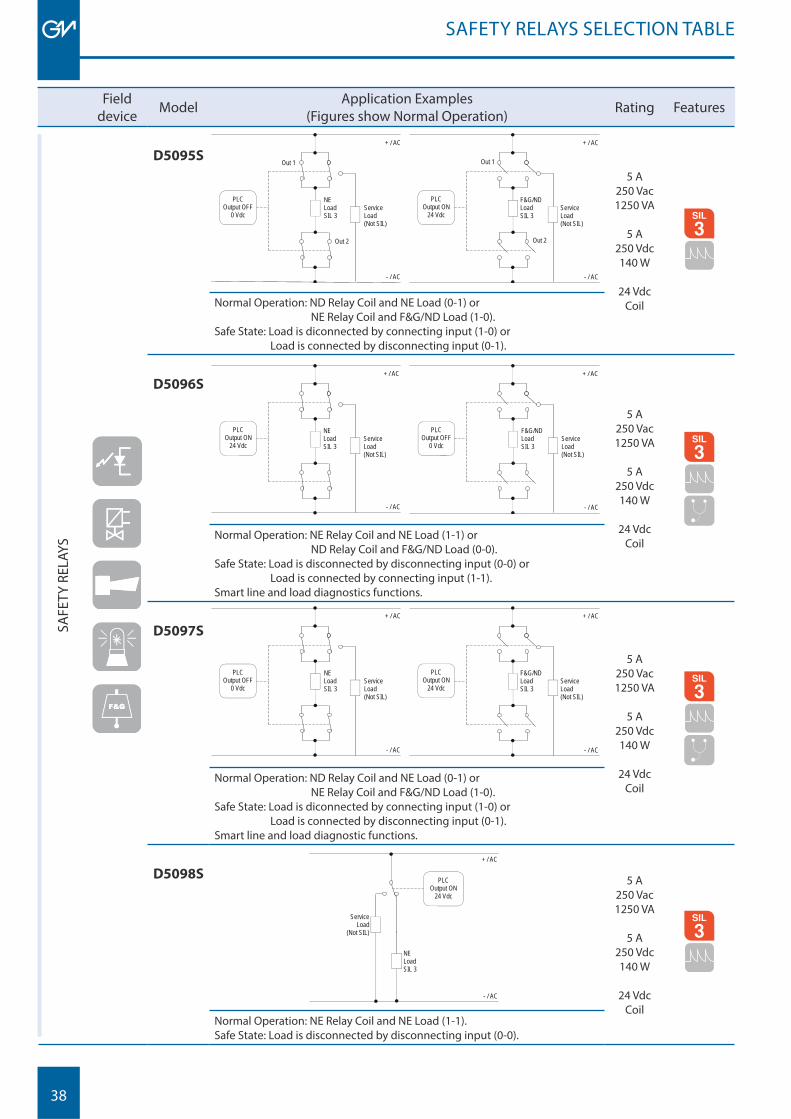
SAFETY RELAYS SELECTION TABLE
Fielddevice Model Application Examples
(Figures show Normal Operation) Rating Features
SAFE
TY R
ELAY
S
D5090S
PLC Output ON
24 Vdc
NE Load SIL 3
Service Load
(Not SIL)
+ / AC
- / AC
PLC Output ON
24 Vdc NE Load SIL 3
Service Load
(Not SIL)
- / AC
+ / AC
5 A250 Vac1250 VA
5 A250 Vdc140 W
24 VdcCoil
MODBUS
Normal Operation: NE Relay Coil and NE Load (1-1).Safe State: Load is disconnected by disconnecting input (0-0).
D5090S-
086 PLC Output OFF
0 Vdc
NE Load SIL 3
Service Load
(Not SIL)
+ / AC
- / AC
PLC Output OFF
0 Vdc NE Load SIL 3
Service Load
(Not SIL)
- / AC
+ / AC
5 A250 Vac1250 VA
5 A250 Vdc140 W
24 VdcCoil
MODBUS
Normal Operation: ND Relay Coil and NE Load (0-1).Safe State: Load is disconnected by connecting input (1-0).
D5091S
Load SIL3
- / AC
+ / AC
PLC Output OFF
0 Vdc
Service Load ND
- / AC
+ / AC
PLC Output ON
24 Vdc
Service Load Load SIL3
ND
5 A250 Vac1250 VA
5 A250 Vdc140 W
24 VdcCoil
MODBUS
Normal Operation: ND or NE Relay Coil and ND Load (0-0 or 1-0).Safe State: Load is connected by connecting input (1-1) or by disconnecting input (0-1).
D5094S
- / AC
+ / AC
PLC Output ON
24 Vdc
NE Load SIL 3
Service Load (Not SIL)
Out 1
Out 2
- / AC
+ / AC
PLC Output OFF
0 Vdc
F&G/ND Load SIL 3
Service Load (Not SIL)
Out 1
Out 2
5 A250 Vac1250 VA
5 A250 Vdc140 W
24 VdcCoil
MODBUS
Normal Operation: NE Relay Coil and NE Load (1-1) or ND Relay Coil and F&G/ND Load (0-0).Safe State: Load is disconnected by disconnecting input (0-0) or Load is connected by connecting input (1-1).
38
SAFETY RELAYS SELECTION TABLE
Fielddevice Model Application Examples
(Figures show Normal Operation) Rating Features
SAFE
TY R
ELAY
S
D5095S
- / AC
+ / AC
NE Load SIL 3
Service Load (Not SIL)
Out 1
Out 2
- / AC
+ / AC
PLC Output ON
24 Vdc
F&G/ND Load SIL 3
Service Load (Not SIL)
PLC Output OFF
0 Vdc
Out 1
Out 2
5 A250 Vac1250 VA
5 A250 Vdc140 W
24 VdcCoil
MODBUS
Normal Operation: ND Relay Coil and NE Load (0-1) or NE Relay Coil and F&G/ND Load (1-0).Safe State: Load is diconnected by connecting input (1-0) or Load is connected by disconnecting input (0-1).
D5096S
- / AC
+ / AC
PLC Output ON
24 Vdc
NE Load SIL 3
Service Load (Not SIL)
- / AC
+ / AC
PLC Output OFF
0 Vdc
F&G/ND Load SIL 3
Service Load (Not SIL)
5 A250 Vac1250 VA
5 A250 Vdc140 W
24 VdcCoil
MODBUS
Normal Operation: NE Relay Coil and NE Load (1-1) or ND Relay Coil and F&G/ND Load (0-0).Safe State: Load is disconnected by disconnecting input (0-0) or Load is connected by connecting input (1-1).Smart line and load diagnostics functions.
D5097S
- / AC
+ / AC
NE Load SIL 3
Service Load (Not SIL)
- / AC
+ / AC
PLC Output ON
24 Vdc
F&G/ND Load SIL 3
Service Load (Not SIL)
PLC Output OFF
0 Vdc
5 A250 Vac1250 VA
5 A250 Vdc140 W
24 VdcCoil
MODBUS
Normal Operation: ND Relay Coil and NE Load (0-1) or NE Relay Coil and F&G/ND Load (1-0).Safe State: Load is diconnected by connecting input (1-0) or Load is connected by disconnecting input (0-1).Smart line and load diagnostic functions.
D5098S PLC Output ON
24 Vdc
NE Load SIL 3
Service Load
(Not SIL)
+ / AC
- / AC
5 A250 Vac1250 VA
5 A250 Vdc140 W
24 VdcCoil
MODBUS
Normal Operation: NE Relay Coil and NE Load (1-1).Safe State: Load is disconnected by disconnecting input (0-0).
39
SAFETY RELAYS SELECTION TABLE
Fielddevice Model Application Examples
(Figures show Normal Operation) Rating Features
SAFE
TY R
ELAY
S
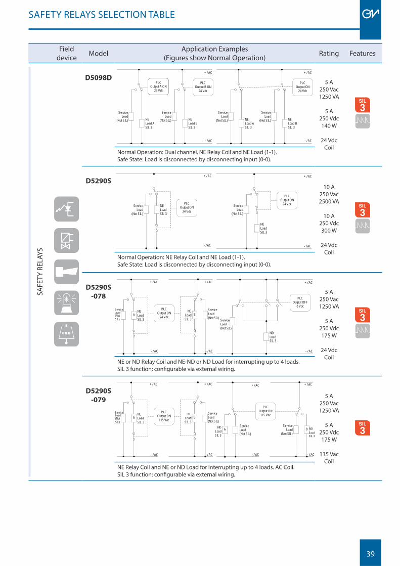
D5098DPLC
Output ON 24 Vdc
NE Load B SIL 3
Service Load
(Not SIL)
+ / AC
- / AC
Service Load
(Not SIL) NE Load A SIL 3
PLC Output B ON
24 Vdc
NE Load B SIL 3
Service Load
(Not SIL)
+ / AC
- / AC
Service Load
(Not SIL) NE Load A SIL 3
24 Vdc Output A ON
PLC
5 A250 Vac1250 VA
5 A250 Vdc140 W
24 VdcCoil
MODBUS
Normal Operation: Dual channel. NE Relay Coil and NE Load (1-1).Safe State: Load is disconnected by disconnecting input (0-0).
D5290S
PLC Output ON
24 Vdc NE Load SIL 3
Service Load
(Not SIL)
- / AC
+ / AC
PLC Output ON
24 Vdc
NE Load SIL 3
Service Load
(Not SIL)
+ / AC
- / AC
10 A250 Vac2500 VA
10 A250 Vdc300 W
24 VdcCoil
MODBUS
Normal Operation: NE Relay Coil and NE Load (1-1).Safe State: Load is disconnected by disconnecting input (0-0).
D5290S
-078
B NE
Load SIL 3
PLC Output ON
24 Vdc
Service Load (Not SIL)
A NE Load SIL 3
Service Load (Not SIL)
- / AC
+ / AC + / AC
- / AC
PLC Output OFF
0 Vdc
ND Load SIL 3
Service Load (Not SIL)
+ / AC
- / AC
5 A250 Vac1250 VA
5 A250 Vdc175 W
24 VdcCoil
MODBUS
NE or ND Relay Coil and NE-ND or ND Load for interrupting up to 4 loads.SIL 3 function: confi gurable via external wiring.
D5290S
-079
B NE
Load SIL 3
PLC Output ON
115 Vac
Service Load (Not SIL)
A NE Load SIL 3
Service Load (Not SIL)
- / AC
+ / AC + / AC
- / AC
PLC Output ON
115 Vac
B Service
Load (Not SIL)
ND Load SIL 3
A Service Load (Not SIL)
ND Load SIL 3
+ / AC + / AC
- / AC - / AC
5 A250 Vac1250 VA
5 A250 Vdc175 W
115 VacCoil
MODBUS
NE Relay Coil and NE or ND Load for interrupting up to 4 loads. AC Coil.SIL 3 function: confi gurable via external wiring.
40
Fielddevice Model Application Examples
(Figures show Normal Operation) Rating Features
SAFE
TY R
ELAY
S
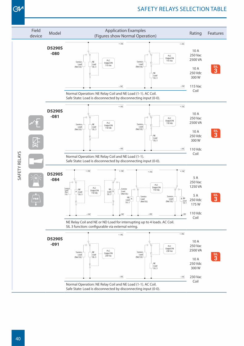
D5290S
-080
PLC Output ON
115 Vac NE Load SIL 3
Service Load
(Not SIL)
- / AC
+ / AC
PLC Output ON
115 Vac
NE Load SIL 3
Service Load
(Not SIL)
+ / AC
- / AC
10 A250 Vac2500 VA
10 A250 Vdc300 W
115 VacCoil
MODBUS
Normal Operation: NE Relay Coil and NE Load (1-1). AC Coil.Safe State: Load is disconnected by disconnecting input (0-0).
D5290S
-081
PLC Output ON
110 Vdc NE Load SIL 3
Service Load
(Not SIL)
- / AC
+ / AC
PLC Output ON
110 Vdc
NE Load SIL 3
Service Load
(Not SIL)
+ / AC
- / AC
10 A250 Vac2500 VA
10 A250 Vdc300 W
110 VdcCoil
MODBUS
Normal Operation: NE Relay Coil and NE Load (1-1).Safe State: Load is disconnected by disconnecting input (0-0).
D5290S
-084
B NE
Load SIL 3
PLC Output ON
110 Vdc
Service Load (Not SIL)
A NE Load SIL 3
Service Load (Not SIL)
- / AC
+ / AC + / AC
- / AC
PLC Output ON
110 Vdc
B Service
Load (Not SIL)
ND Load SIL 3
A Service Load (Not SIL)
ND Load SIL 3
+ / AC + / AC
- / AC - / AC
5 A250 Vac1250 VA
5 A250 Vdc175 W
110 VdcCoil
MODBUS
NE Relay Coil and NE or ND Load for interrupting up to 4 loads. AC Coil.SIL 3 function: confi gurable via external wiring.
D5290S
-091
PLC Output ON
230 Vac NE Load SIL 3
Service Load
(Not SIL)
- / AC
+ / AC
PLC Output ON
230 Vac
NE Load SIL 3
Service Load
(Not SIL)
+ / AC
- / AC
10 A250 Vac2500 VA
10 A250 Vdc300 W
230 VacCoil
MODBUS
Normal Operation: NE Relay Coil and NE Load (1-1). AC Coil.Safe State: Load is disconnected by disconnecting input (0-0).
SAFETY RELAYS SELECTION TABLE
41
Fielddevice Model Application Examples
(Figures show Normal Operation) Rating Features
SAFE
TY R
ELAY
S
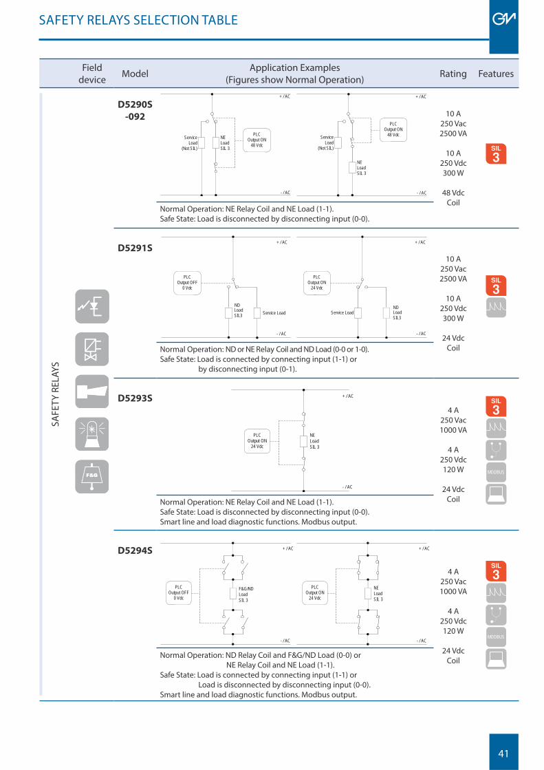
D5290S
-092
PLC Output ON
48 Vdc NE Load SIL 3
Service Load
(Not SIL)
- / AC
+ / AC
PLC Output ON
48 Vdc
NE Load SIL 3
Service Load
(Not SIL)
+ / AC
- / AC
10 A250 Vac2500 VA
10 A250 Vdc300 W
48 VdcCoil
MODBUS
Normal Operation: NE Relay Coil and NE Load (1-1).Safe State: Load is disconnected by disconnecting input (0-0).
D5291S
Load SIL3
- / AC
+ / AC
PLC Output OFF
0 Vdc
Service Load ND
- / AC
+ / AC
PLC Output ON
24 Vdc
Service Load Load SIL3
ND
10 A250 Vac2500 VA
10 A250 Vdc300 W
24 VdcCoil
MODBUS
Normal Operation: ND or NE Relay Coil and ND Load (0-0 or 1-0).Safe State: Load is connected by connecting input (1-1) or by disconnecting input (0-1).
D5293S
NELoadSIL 3
- / AC
+ / AC
PLC Output ON
24 Vdc
4 A250 Vac1000 VA
4 A250 Vdc120 W
24 VdcCoil
MODBUS
MODBUS
Normal Operation: NE Relay Coil and NE Load (1-1).Safe State: Load is disconnected by disconnecting input (0-0).Smart line and load diagnostic functions. Modbus output.
D5294S
- / AC
+ / AC
PLC Output OFF
0 Vdc
F&G/NDLoadSIL 3
- / AC
+ / AC
PLC Output ON
24 Vdc
NELoadSIL 3
4 A250 Vac1000 VA
4 A250 Vdc120 W
24 VdcCoil
MODBUS
MODBUS
Normal Operation: ND Relay Coil and F&G/ND Load (0-0) or NE Relay Coil and NE Load (1-1).Safe State: Load is connected by connecting input (1-1) or Load is disconnected by disconnecting input (0-0).Smart line and load diagnostic functions. Modbus output.
SAFETY RELAYS SELECTION TABLE
42
Fielddevice Model Application Examples
(Figures show Normal Operation) Rating Features
SAFE
TY R
ELAY
S
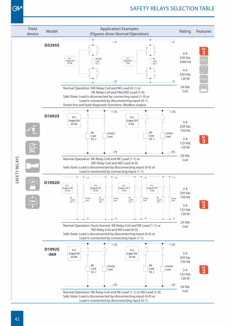
D5295S
- / AC
+ / AC
PLC Output ON
24 Vdc
F&G/NDLoad SIL 3
- / AC
+ / AC
PLC Output OFF
0 Vdc
NELoadSIL 3
4 A250 Vac1000 VA
4 A250 Vdc120 W
24 VdcCoil
MODBUS
MODBUS
Normal Operation: ND Relay Coil and NE Load (0-1) or NE Relay Coil and F&G/ND Load (1-0).Safe State: Load is diconnected by connecting input (1-0) or Load is connected by disconnecting input (0-1).Smart line and load diagnostic functions. Modbus output.
D1092S PLC
24 Vdc
NELoadSIL 3
Service Load
+ / AC
Output ON
- / AC
PLC
0 Vdc
ND LoadSIL 3
Service Load
+ / AC
Output OFF
- / AC
3 A250 Vac750 VA
3 A125 Vdc120 W
24 VdcCoil
MODBUS
Normal Operation: NE Relay Coil and NE Load (1-1) or ND Relay Coil and ND Load (0-0).Safe State: Load is disconnected by disconnecting input (0-0) or Load is connected by connecting input (1-1).
D1092DPLC
Output A ON 24 Vdc
NELoad ASIL 3
Service Load
+ / AC
- / AC
+ / AC
- / AC
+ / AC
- / AC
+ / AC
- / AC
PLC Output B ON
24 Vdc
Service Load
PLC Output A OFF
0 Vdc
Service Load
PLC Output B OFF
0 Vdc
Service Load
NELoad BSIL 3
NDLoad ASIL 3
NDLoad BSIL 3
3 A250 Vac750 VA
3 A125 Vdc120 W
24 VdcCoil
MODBUS
Normal Operation: Dual channel. NE Relay Coil and NE Load (1-1) or ND Relay Coil and ND Load (0-0).Safe State: Load is disconnected by disconnecting input (0-0) or Load is connected by connecting input (1-1).
D1092S
-069PLC
24 Vdc
NE
SIL 3 Load
Service Load
+ / AC
Output ON
- / AC
PLC
24 Vdc
ND
SIL 3 Load
Service Load
+ / AC
Output ON
- / AC
3 A250 Vac750 VA
3 A125 Vdc120 W
24 VdcCoil
MODBUS
Normal Operation: NE Relay Coil and NE Load (1-1) or ND Load (1-0).Safe State: Load is disconnected by disconnecting input (0-0) or Load is connected by disconnecting input (0-1).
SAFETY RELAYS SELECTION TABLE
43
SAFETY RELAYS SELECTION TABLE
Fielddevice Model Application Examples
(Figures show Normal Operation) Rating Features
SAFE
TY R
ELAY
S
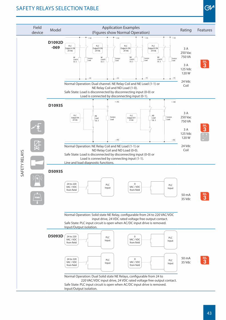
D1092D
-069PLC
Output A ON 24 Vdc
NE
SIL 3 Load A Service
Load
+ / AC
- / AC
+ / AC
- / AC
+ / AC
- / AC
+ / AC
- / AC
PLC Output B ON
24 Vdc
Service Load
PLC Output A ON
24 Vdc
Service Load
PLC Output B ON
24 Vdc
Service Load
NE
SIL 3 Load B
ND
SIL 3 Load A
ND
SIL 3 Load B
3 A250 Vac750 VA
3 A125 Vdc120 W
24 VdcCoil
MODBUS
Normal Operation: Dual channel. NE Relay Coil and NE Load (1-1) or NE Relay Coil and ND Load (1-0).Safe State: Load is disconnected by disconnecting input (0-0) or Load is connected by disconnecting input (0-1).
D1093S
NE
SIL 3 Load
+ / AC
PLC Output ON
24 Vdc Service Load
- / AC
PLC Output OFF
0 Vdc Service Load
+ / AC
- / AC
ND
SIL 3 Load
3 A250 Vac750 VA
3 A125 Vdc120 W
24 VdcCoil
MODBUS
Normal Operation: NE Relay Coil and NE Load (1-1) or ND Relay Coil and ND Load (0-0).Safe State: Load is disconnected by disconnecting input (0-0) or Load is connected by connecting input (1-1).Line and load diagnostic functions.
D5093S
24 to 220 VAC / VDCfrom field
0VAC / VDCfrom field
PLC Input
PLC Input
50 mA35 Vdc
MODBUS
Normal Operation: Solid state NE Relay, confi gurable from 24 to 220 VAC/VDC input drive, 24 VDC rated voltage free output contact.Safe State: PLC input circuit is open when AC/DC input drive is removed.Input/Output isolation.
D5093D 24 to 220 VAC / VDCfrom field
0VAC / VDCfrom field
PLC Input
PLC Input
24 to 220 VAC / VDCfrom field
0VAC / VDCfrom field
PLC Input
PLC Input
50 mA35 Vdc
MODBUS
Normal Operation: Dual Solid state NE Relays, confi gurable from 24 to 220 VAC/VDC input drive, 24 VDC rated voltage free output contact.Safe State: PLC input circuit is open when AC/DC input drive is removed. Input/Output isolation.

44
45
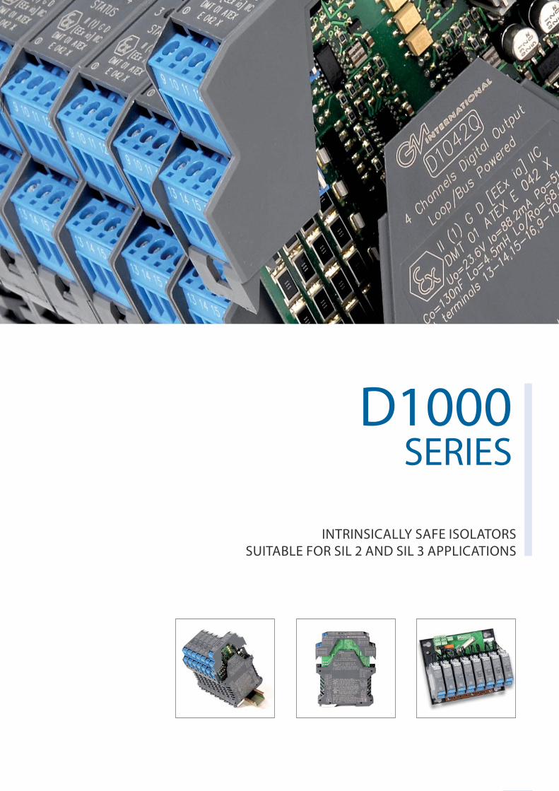
D1000 SERIES
INTRINSICALLY SAFE ISOLATORSSUITABLE FOR SIL 2 AND SIL 3 APPLICATIONS
D1000 SERIES
46
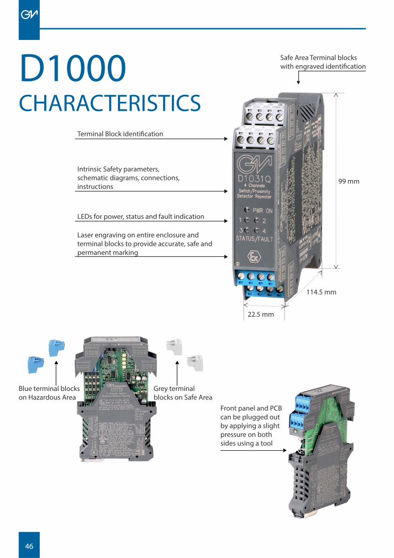
D1000 Safe Area Terminal blocks with engraved identifi cation
Terminal Block identifi cation
Intrinsic Safety parameters,schematic diagrams, connections, instructions
LEDs for power, status and fault indication
Laser engraving on entire enclosure and terminal blocks to provide accurate, safe and permanent marking
CHARACTERISTICS
Blue terminal blocks on Hazardous Area
Grey terminal blocks on Safe Area
99 mm
22.5 mm
114.5 mm
Front panel and PCB can be plugged out by applying a slight pressure on both sides using a tool
47
High Performance
• High signal transfer accuracy and repeatability• Advanced circuitry provides low heat dissipation,
ensuring modules run cool despite their high functionality
• Low power consumption• SMD manufacturing for a long and reliable life
Wide Functionality
• Wide range of Digital and Analog I/Os• Relay contacts rated for 2 A to directly switch high loads• Three port galvanic isolation to eliminate noise,
ground loop problems and to provide Intrinsic Safety without a high integrity safety earth connection
• Line fault alarm detects open or short circuit of fi eld cables
• Optional Power Bus enclosure
General Features
• More than 30 modules suitable for SIL 3 - SIL 2 applications according to IEC61508, IEC61511
• Single channel versions available if required, to provide single loop integrity on Emergency Shut Down and Fire & Gas applications
• Confi guration via DIP switch for easy fi eld setup• LED indication for power, signal status and line
fault conditions• Modules accept DC power supply over a wide
range for 12 or 24 Vdc applications• 2 modules (D1130 - D1180) can be powered from
85 to 264 Vac, 50-400 Hz, or from 100 to 350 Vdc• Wide operating temperature range (-20 / +60°C)
D1000 SERIES
Enclosure Characteristics
• High channel density resulting from innovative circuit design using advanced surface mount components
• Single, dual or quad channel models• Plug-in screw terminal blocks to secure
terminations up to 2.5 mm2
• Plug-in PCB can be removed for confi guration operations
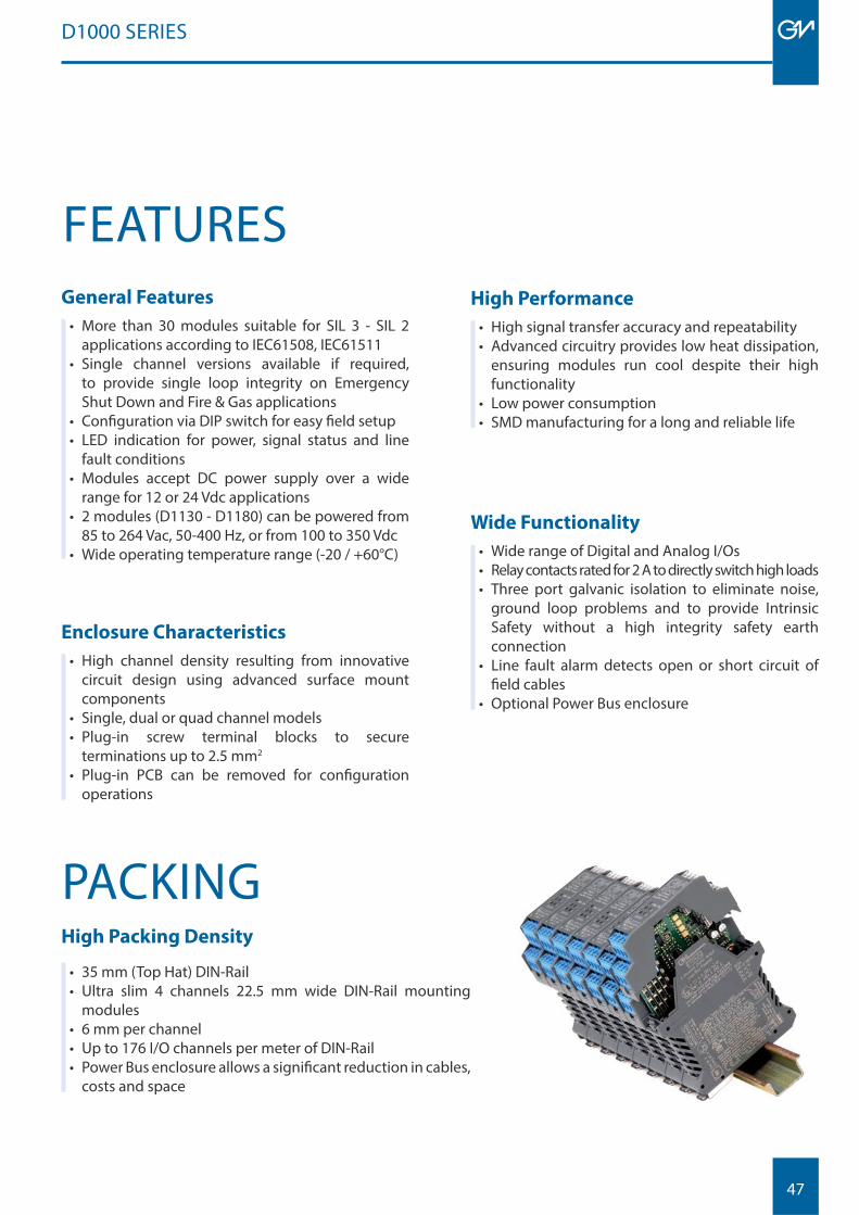
PACKINGHigh Packing Density
• 35 mm (Top Hat) DIN-Rail• Ultra slim 4 channels 22.5 mm wide DIN-Rail mounting
modules• 6 mm per channel• Up to 176 I/O channels per meter of DIN-Rail• Power Bus enclosure allows a signifi cant reduction in cables,
costs and space
FEATURES
48
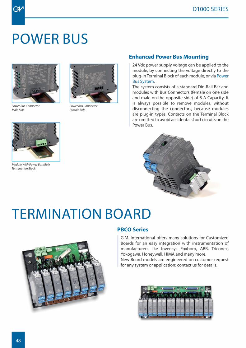
Enhanced Power Bus Mounting
24 Vdc power supply voltage can be applied to the module, by connecting the voltage directly to the plug-in Terminal Block of each module, or via Power Bus System. The system consists of a standard Din-Rail Bar and modules with Bus Connectors (female on one side and male on the opposite side) of 8 A Capacity. It is always possible to remove modules, without disconnecting the connectors, because modules are plug-in types. Contacts on the Terminal Block are omitted to avoid accidental short circuits on the Power Bus.
Power Bus Connector Male Side
Module With Power Bus Male Termination Block
Power Bus ConnectorFemale Side
PBCO Series
G.M. International off ers many solutions for Customized Boards for an easy integration with instrumentation of manufacturers like Invensys Foxboro, ABB, Triconex, Yokogawa, Honeywell, HIMA and many more.New Board models are engineered on customer request for any system or application: contact us for details.
TERMINATION BOARD
POWER BUS
D1000 SERIES
49
D1000 SERIES
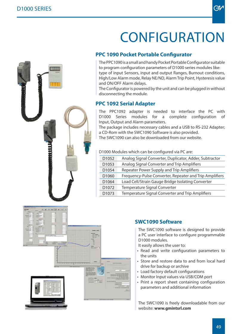
PPC 1090 Pocket Portable Confi gurator
The PPC1090 is a small and handy Pocket Portable Confi gurator suitable to program confi guration parameters of D1000 series modules like: type of input Sensors, input and output Ranges, Burnout conditions, High/Low Alarm mode, Relay NE/ND, Alarm Trip Point, Hysteresis value and ON/OFF Alarm delays. The Confi gurator is powered by the unit and can be plugged in without disconnecting the module.
CONFIGURATION
SWC1090 Software
The SWC1090 software is designed to provide a PC user interface to confi gure programmable D1000 modules.It easily allows the user to:
• Read and write confi guration parameters to the units
• Store and restore data to and from local hard drive for backup or archive
• Load factory default confi gurations• Monitor Input values via USB/COM port• Print a report sheet containing confi guration
parameters and additional information
The SWC1090 is freely downloadable from our website: www.gmintsrl.com
PPC 1092 Serial Adapter
The PPC1092 adapter is needed to interface the PC with D1000 Series modules for a complete confi guration of Input, Output and Alarm parameters.The package includes necessary cables and a USB to RS-232 Adapter; a CD-Rom with the SWC1090 Software is also provided. The SWC1090 can also be downloaded from our website.
D1000 Modules which can be confi gured via PC are:
D1052 Analog Signal Converter, Duplicator, Adder, SubtractorD1053 Analog Signal Converter and Trip Amplifi ersD1054 Repeater Power Supply and Trip Amplifi ersD1060 Frequency-Pulse Converter, Repeater and Trip Amplifi ersD1064 Load Cell/Strain Gauge Bridge Isolating ConverterD1072 Temperature Signal ConverterD1073 Temperature Signal Converter and Trip Amplifi ers
50
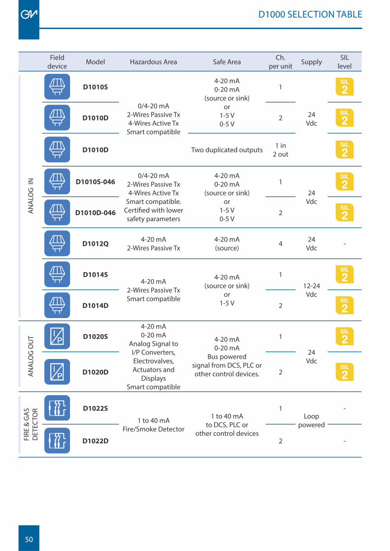
D1000 SELECTION TABLE
Fielddevice Model Hazardous Area Safe Area Ch.
per unit Supply SIL level
AN
ALO
G I
N
D1010S
0/4-20 mA2-Wires Passive Tx4-Wires Active Tx
Smart compatible
4-20 mA0-20 mA
(source or sink)or
1-5 V0-5 V
1
24Vdc
D1010D 2
D1010D Two duplicated outputs 1 in2 out
D1010S-0460/4-20 mA
2-Wires Passive Tx4-Wires Active Tx
Smart compatible.Certifi ed with lower safety parameters
4-20 mA0-20 mA
(source or sink)or
1-5 V0-5 V
1
24Vdc
D1010D-046 2
D1012Q4-20 mA
2-Wires Passive Tx4-20 mA(source) 4 24
Vdc -
D1014S4-20 mA
2-Wires Passive TxSmart compatible
4-20 mA(source or sink)
or1-5 V
1
12-24 Vdc
D1014D 2
AN
ALO
G O
UT D1020S
4-20 mA0-20 mA
Analog Signal toI/P Converters, Electrovalves,Actuators and
DisplaysSmart compatible
4-20 mA0-20 mA
Bus powered signal from DCS, PLC or other control devices.
1
24 Vdc
D1020D 2
FIRE
& G
AS
DET
ECTO
R D1022S
1 to 40 mAFire/Smoke Detector
1 to 40 mAto DCS, PLC or
other control devices
1Loop
powered
-
D1022D 2 -
51
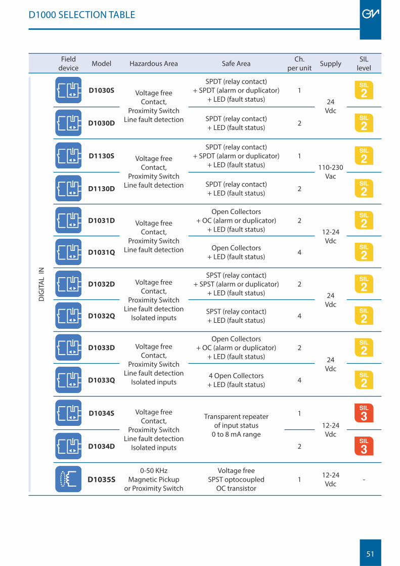
Fielddevice Model Hazardous Area Safe Area Ch.
per unit Supply SIL level
DIG
ITA
L IN
D1030S Voltage free Contact,
Proximity SwitchLine fault detection
SPDT (relay contact) + SPDT (alarm or duplicator)
+ LED (fault status)1
24 Vdc
D1030DSPDT (relay contact)+ LED (fault status) 2
D1130S Voltage free Contact,
Proximity Switch Line fault detection
SPDT (relay contact) + SPDT (alarm or duplicator)
+ LED (fault status)1
110-230 Vac
D1130DSPDT (relay contact)+ LED (fault status) 2
D1031D Voltage free Contact,
Proximity SwitchLine fault detection
Open Collectors + OC (alarm or duplicator)
+ LED (fault status) 2
12-24 Vdc
D1031QOpen Collectors
+ LED (fault status) 4
D1032D Voltage free Contact,
Proximity SwitchLine fault detection
Isolated inputs
SPST (relay contact)+ SPST (alarm or duplicator)
+ LED (fault status)2
24Vdc
D1032QSPST (relay contact)+ LED (fault status) 4
D1033D Voltage free Contact,
Proximity SwitchLine fault detection
Isolated inputs
Open Collectors + OC (alarm or duplicator)
+ LED (fault status) 2
24Vdc
D1033Q4 Open Collectors + LED (fault status) 4
D1034S Voltage free Contact,
Proximity SwitchLine fault detection
Isolated inputs
Transparent repeaterof input status
0 to 8 mA range
1
12-24 Vdc
MODBUS
D1034D 2 MODBUS
D1035S
0-50 KHzMagnetic Pickup
or Proximity Switch
Voltage free SPST optocoupled
OC transistor1 12-24
Vdc -
D1000 SELECTION TABLE
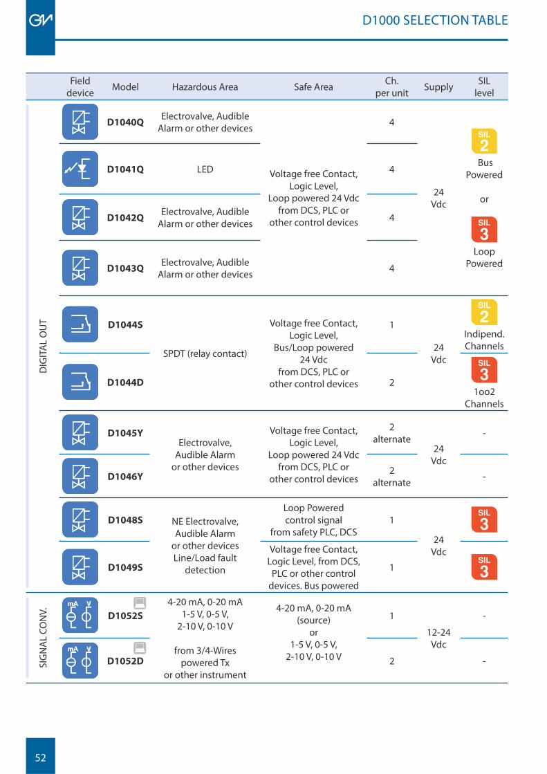
52
Fielddevice Model Hazardous Area Safe Area Ch.
per unit Supply SIL level
DIG
ITA
L O
UT
D1040QElectrovalve, Audible
Alarm or other devices
Voltage free Contact,Logic Level,
Loop powered 24 Vdc from DCS, PLC or
other control devices
4
24Vdc
Bus Powered
or
MODBUS
Loop Powered
D1041Q LED 4
D1042QElectrovalve, Audible
Alarm or other devices 4
D1043QElectrovalve, Audible
Alarm or other devices 4
D1044S
SPDT (relay contact)
Voltage free Contact,Logic Level,
Bus/Loop powered24 Vdc
from DCS, PLC or other control devices
1
24 Vdc
Indipend.Channels
D1044D 2MODBUS
1oo2 Channels
D1045YElectrovalve,
Audible Alarm or other devices
Voltage free Contact,Logic Level,
Loop powered 24 Vdc from DCS, PLC or
other control devices
2alternate
24Vdc
-
D1046Y2
alternate -
D1048S NE Electrovalve, Audible Alarm
or other devicesLine/Load fault
detection
Loop Powered control signal
from safety PLC, DCS1
24 Vdc
MODBUS
D1049S
Voltage free Contact,Logic Level, from DCS,
PLC or other control devices. Bus powered
1 MODBUS
SIG
NA
L CO
NV. D1052S
4-20 mA, 0-20 mA1-5 V, 0-5 V,
2-10 V, 0-10 V
from 3/4-Wires powered Tx
or other instrument
4-20 mA, 0-20 mA(source)
or1-5 V, 0-5 V,
2-10 V, 0-10 V
1
12-24Vdc
-
D1052D 2 -
D1000 SELECTION TABLE
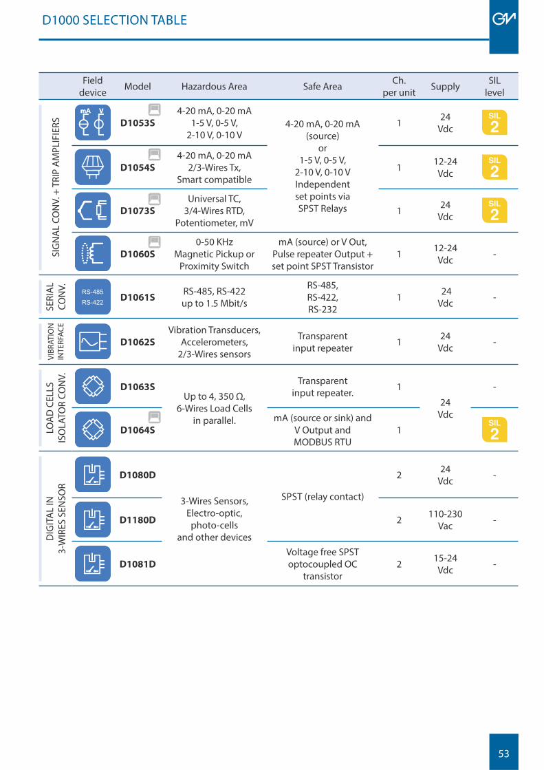
53
Fielddevice Model Hazardous Area Safe Area Ch.
per unit Supply SIL level
SIG
NA
L CO
NV.
+ T
RIP
AM
PLIF
IERS D1053S
4-20 mA, 0-20 mA1-5 V, 0-5 V,
2-10 V, 0-10 V4-20 mA, 0-20 mA
(source)or
1-5 V, 0-5 V, 2-10 V, 0-10 VIndependentset points viaSPST Relays
1 24Vdc
D1054S
4-20 mA, 0-20 mA2/3-Wires Tx,
Smart compatible1 12-24
Vdc
D1073S
Universal TC, 3/4-Wires RTD,
Potentiometer, mV1 24
Vdc
D1060S
0-50 KHz Magnetic Pickup or
Proximity Switch
mA (source) or V Out,Pulse repeater Output + set point SPST Transistor
1 12-24 Vdc -
SERI
AL
CON
V. RS-485RS-422 D1061S
RS-485, RS-422up to 1.5 Mbit/s
RS-485, RS-422,RS-232
1 24Vdc -
VIBR
ATIO
N
INTE
RFAC
E
D1062S
Vibration Transducers,Accelerometers,
2/3-Wires sensors
Transparent input repeater 1 24
Vdc -
LOA
D C
ELLS
ISO
LATO
R CO
NV.
D1063SUp to 4, 350 Ω,
6-Wires Load Cellsin parallel.
Transparent input repeater. 1
24 Vdc
-
D1064S
mA (source or sink) and V Output and MODBUS RTU
1
DIG
ITA
L IN
3-
WIR
ES S
ENSO
R D1080D
3-Wires Sensors,Electro-optic,
photo-cellsand other devices
SPST (relay contact)
2 24 Vdc -
D1180D 2 110-230 Vac -
D1081D
Voltage free SPST optocoupled OC
transistor2 15-24
Vdc -
D1000 SELECTION TABLE
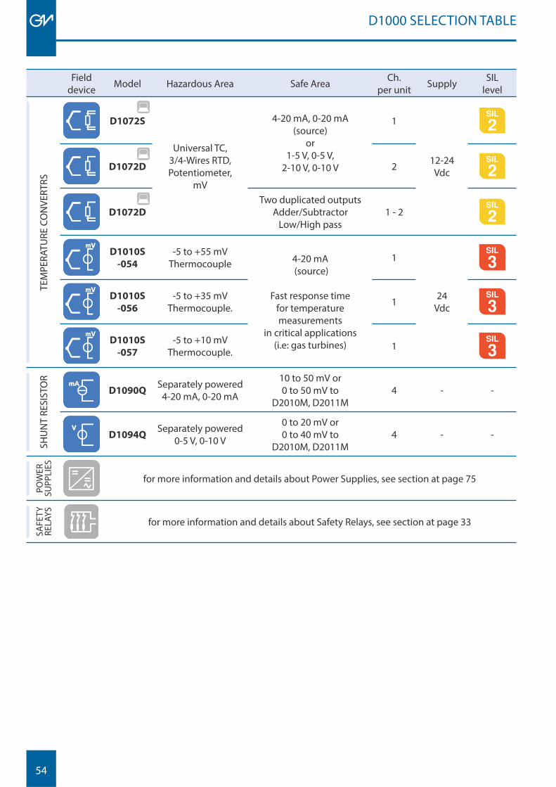
54
Fielddevice Model Hazardous Area Safe Area Ch.
per unit Supply SIL level
TEM
PERA
TURE
CO
NVE
RTRS
D1072S
Universal TC, 3/4-Wires RTD,Potentiometer,
mV
4-20 mA, 0-20 mA(source)
or1-5 V, 0-5 V,
2-10 V, 0-10 V
1
12-24 VdcD1072D 2
D1072D
Two duplicated outputsAdder/Subtractor
Low/High pass1 - 2
D1010S
-054
-5 to +55 mVThermocouple 4-20 mA
(source)
Fast response timefor temperature measurements
in critical applications(i.e: gas turbines)
1
24Vdc
MODBUS
D1010S
-056
-5 to +35 mVThermocouple. 1 MODBUS
D1010S
-057
-5 to +10 mVThermocouple. 1 MODBUS
SHU
NT
RESI
STO
R
D1090QSeparately powered
4-20 mA, 0-20 mA
10 to 50 mV or 0 to 50 mV to
D2010M, D2011M4 - -
D1094QSeparately powered
0-5 V, 0-10 V
0 to 20 mV or 0 to 40 mV to
D2010M, D2011M4 - -
POW
ER
SUPP
LIES
for more information and details about Power Supplies, see section at page 75
SAFE
TY
RELA
YS
for more information and details about Safety Relays, see section at page 33
D1000 SELECTION TABLE
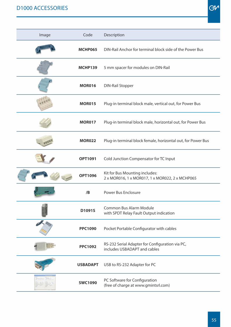
55
Image Code Description
MCHP065 DIN-Rail Anchor for terminal block side of the Power Bus
MCHP139 5 mm spacer for modules on DIN-Rail
MOR016 DIN-Rail Stopper
MOR015 Plug-in terminal block male, vertical out, for Power Bus
MOR017 Plug-in terminal block male, horizontal out, for Power Bus
MOR022 Plug-in terminal block female, horizontal out, for Power Bus
OPT1091 Cold Junction Compensator for TC Input
OPT1096Kit for Bus Mounting includes: 2 x MOR016, 1 x MOR017, 1 x MOR022, 2 x MCHP065
/B Power Bus Enclosure
D1091SCommon Bus Alarm Module with SPDT Relay Fault Output indication
PPC1090 Pocket Portable Confi gurator with cables
PPC1092RS-232 Serial Adapter for Confi guration via PC, includes USBADAPT and cables
USBADAPT USB to RS-232 Adapter for PC
SWC1090PC Software for Confi guration (free of charge at www.gmintsrl.com)
D1000 ACCESSORIES
56
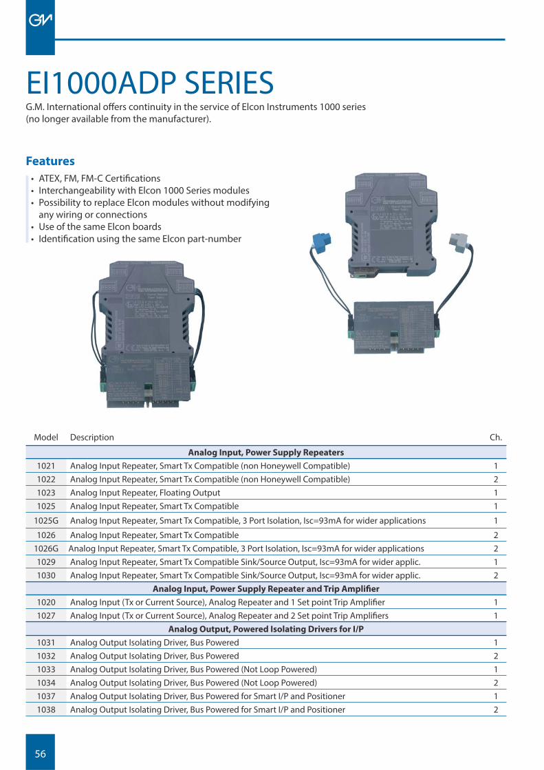
EI1000ADP SERIESG.M. International off ers continuity in the service of Elcon Instruments 1000 series(no longer available from the manufacturer).
Features
• ATEX, FM, FM-C Certifi cations• Interchangeability with Elcon 1000 Series modules• Possibility to replace Elcon modules without modifying
any wiring or connections• Use of the same Elcon boards• Identifi cation using the same Elcon part-number
Model Description Ch.
Analog Input, Power Supply Repeaters
1021 Analog Input Repeater, Smart Tx Compatible (non Honeywell Compatible) 11022 Analog Input Repeater, Smart Tx Compatible (non Honeywell Compatible) 21023 Analog Input Repeater, Floating Output 11025 Analog Input Repeater, Smart Tx Compatible 1
1025G Analog Input Repeater, Smart Tx Compatible, 3 Port Isolation, Isc=93mA for wider applications 1
1026 Analog Input Repeater, Smart Tx Compatible 21026G Analog Input Repeater, Smart Tx Compatible, 3 Port Isolation, Isc=93mA for wider applications 21029 Analog Input Repeater, Smart Tx Compatible Sink/Source Output, Isc=93mA for wider applic. 11030 Analog Input Repeater, Smart Tx Compatible Sink/Source Output, Isc=93mA for wider applic. 2
Analog Input, Power Supply Repeater and Trip Amplifi er
1020 Analog Input (Tx or Current Source), Analog Repeater and 1 Set point Trip Amplifi er 11027 Analog Input (Tx or Current Source), Analog Repeater and 2 Set point Trip Amplifi ers 1
Analog Output, Powered Isolating Drivers for I/P
1031 Analog Output Isolating Driver, Bus Powered 11032 Analog Output Isolating Driver, Bus Powered 21033 Analog Output Isolating Driver, Bus Powered (Not Loop Powered) 11034 Analog Output Isolating Driver, Bus Powered (Not Loop Powered) 21037 Analog Output Isolating Driver, Bus Powered for Smart I/P and Positioner 11038 Analog Output Isolating Driver, Bus Powered for Smart I/P and Positioner 2
57
Model Description Ch.
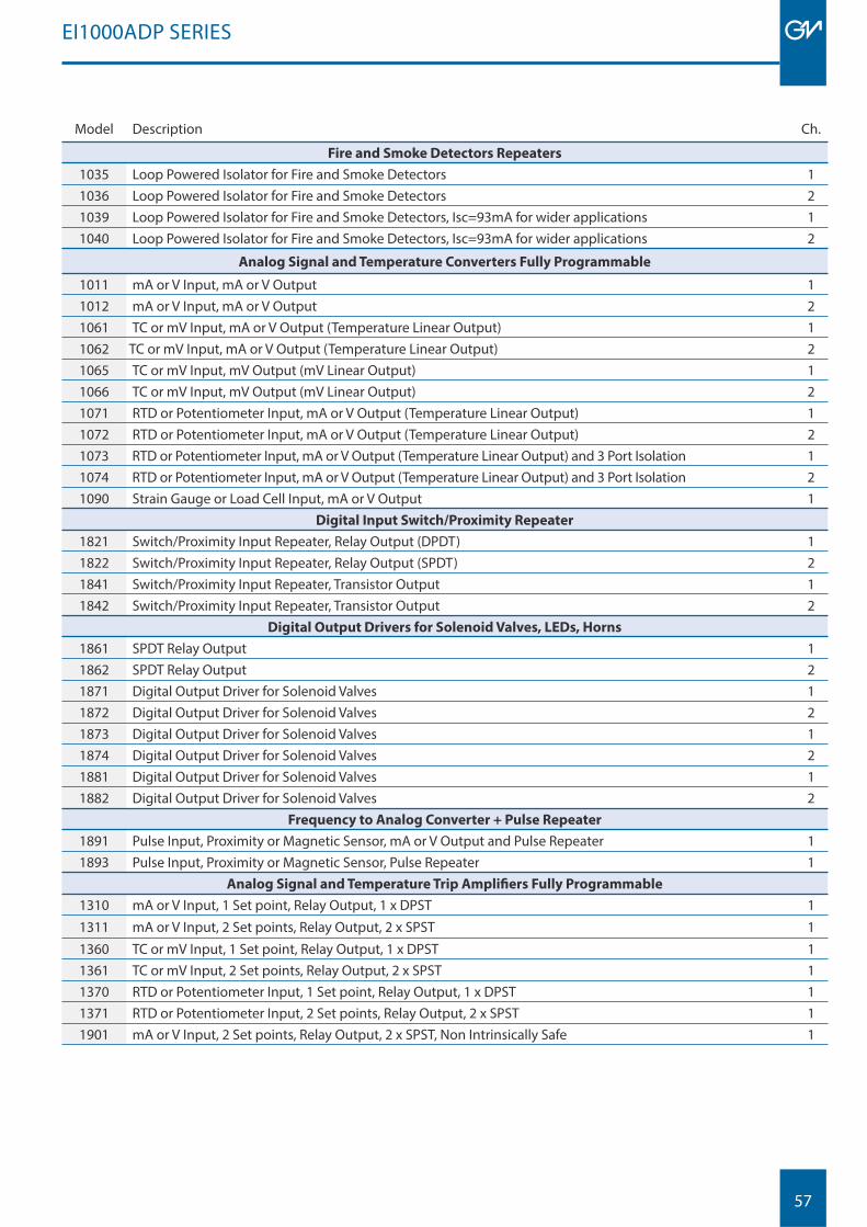
Fire and Smoke Detectors Repeaters
1035 Loop Powered Isolator for Fire and Smoke Detectors 11036 Loop Powered Isolator for Fire and Smoke Detectors 21039 Loop Powered Isolator for Fire and Smoke Detectors, Isc=93mA for wider applications 11040 Loop Powered Isolator for Fire and Smoke Detectors, Isc=93mA for wider applications 2
Analog Signal and Temperature Converters Fully Programmable
1011 mA or V Input, mA or V Output 11012 mA or V Input, mA or V Output 21061 TC or mV Input, mA or V Output (Temperature Linear Output) 11062 TC or mV Input, mA or V Output (Temperature Linear Output) 21065 TC or mV Input, mV Output (mV Linear Output) 11066 TC or mV Input, mV Output (mV Linear Output) 21071 RTD or Potentiometer Input, mA or V Output (Temperature Linear Output) 11072 RTD or Potentiometer Input, mA or V Output (Temperature Linear Output) 21073 RTD or Potentiometer Input, mA or V Output (Temperature Linear Output) and 3 Port Isolation 11074 RTD or Potentiometer Input, mA or V Output (Temperature Linear Output) and 3 Port Isolation 21090 Strain Gauge or Load Cell Input, mA or V Output 1
Digital Input Switch/Proximity Repeater 1821 Switch/Proximity Input Repeater, Relay Output (DPDT) 11822 Switch/Proximity Input Repeater, Relay Output (SPDT) 21841 Switch/Proximity Input Repeater, Transistor Output 11842 Switch/Proximity Input Repeater, Transistor Output 2
Digital Output Drivers for Solenoid Valves, LEDs, Horns
1861 SPDT Relay Output 11862 SPDT Relay Output 21871 Digital Output Driver for Solenoid Valves 11872 Digital Output Driver for Solenoid Valves 21873 Digital Output Driver for Solenoid Valves 11874 Digital Output Driver for Solenoid Valves 21881 Digital Output Driver for Solenoid Valves 11882 Digital Output Driver for Solenoid Valves 2
Frequency to Analog Converter + Pulse Repeater
1891 Pulse Input, Proximity or Magnetic Sensor, mA or V Output and Pulse Repeater 11893 Pulse Input, Proximity or Magnetic Sensor, Pulse Repeater 1
Analog Signal and Temperature Trip Amplifi ers Fully Programmable
1310 mA or V Input, 1 Set point, Relay Output, 1 x DPST 1
1311 mA or V Input, 2 Set points, Relay Output, 2 x SPST 1
1360 TC or mV Input, 1 Set point, Relay Output, 1 x DPST 11361 TC or mV Input, 2 Set points, Relay Output, 2 x SPST 11370 RTD or Potentiometer Input, 1 Set point, Relay Output, 1 x DPST 11371 RTD or Potentiometer Input, 2 Set points, Relay Output, 2 x SPST 11901 mA or V Input, 2 Set points, Relay Output, 2 x SPST, Non Intrinsically Safe 1
EI1000ADP SERIES

58
59
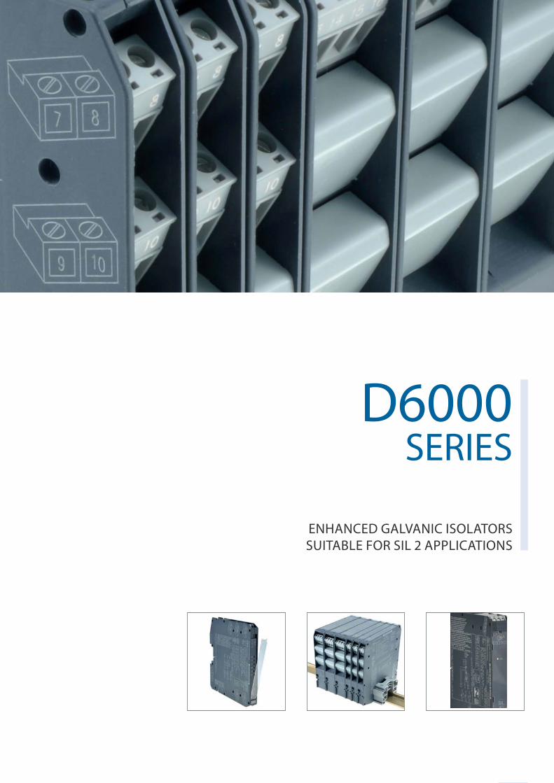
D6000SERIES
ENHANCED GALVANIC ISOLATORS SUITABLE FOR SIL 2 APPLICATIONS
60
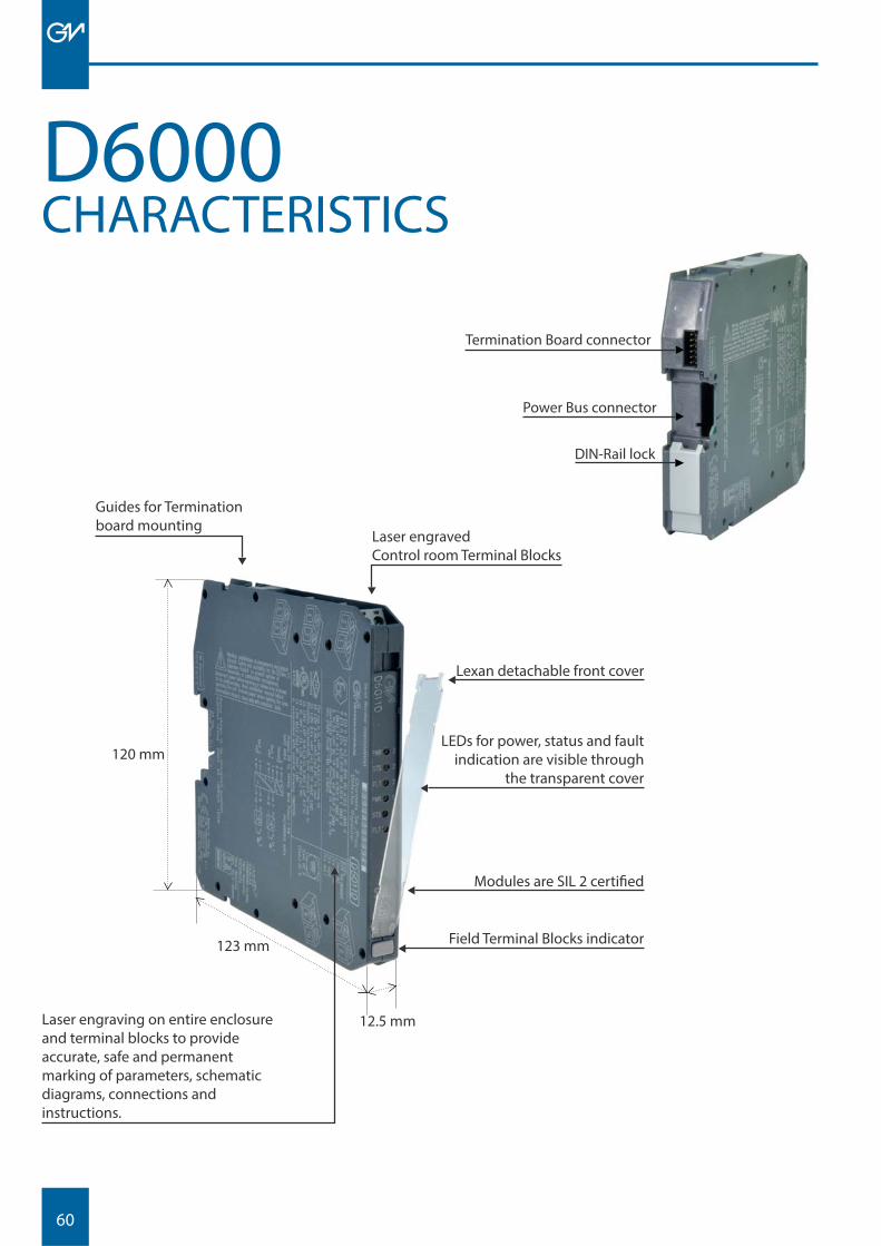
DIN-Rail lock
Power Bus connector
Termination Board connector
CHARACTERISTICSD6000
Guides for Termination board mounting
Laser engravedControl room Terminal Blocks
Lexan detachable front cover
LEDs for power, status and fault indication are visible through
the transparent cover
Modules are SIL 2 certifi ed
Field Terminal Blocks indicator
Laser engraving on entire enclosure and terminal blocks to provide accurate, safe and permanent marking of parameters, schematic diagrams, connections and instructions.
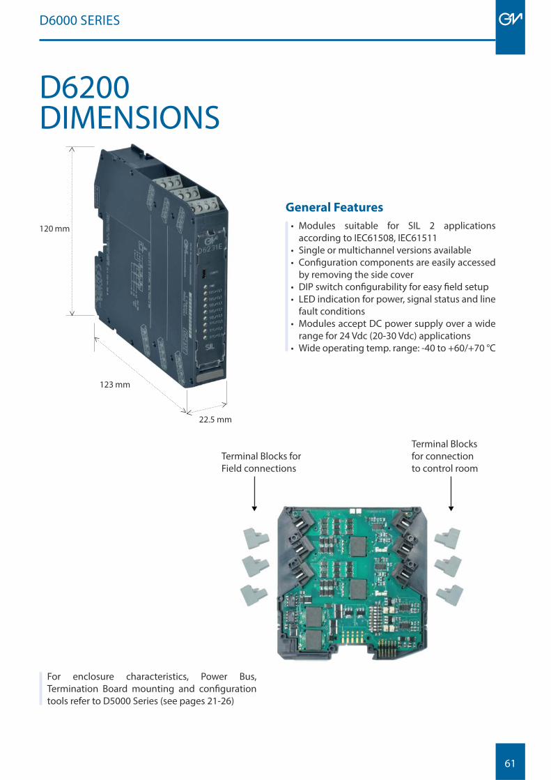
120 mm
123 mm
12.5 mm
61
D6000 SERIES
General Features
• Modules suitable for SIL 2 applications according to IEC61508, IEC61511
• Single or multichannel versions available• Confi guration components are easily accessed
by removing the side cover• DIP switch confi gurability for easy fi eld setup• LED indication for power, signal status and line
fault conditions• Modules accept DC power supply over a wide
range for 24 Vdc (20-30 Vdc) applications• Wide operating temp. range: -40 to +60/+70 °C
Terminal Blocks for Field connections
Terminal Blocks for connection to control room
For enclosure characteristics, Power Bus, Termination Board mounting and confi guration tools refer to D5000 Series (see pages 21-26)
120 mm
22.5 mm
123 mm
D6200DIMENSIONS
62
D6000 SERIES
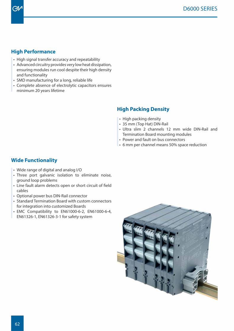
High Performance
• High signal transfer accuracy and repeatability• Advanced circuitry provides very low heat dissipation,
ensuring modules run cool despite their high density and functionality
• SMD manufacturing for a long, reliable life• Complete absence of electrolytic capacitors ensures
minimum 20 years lifetime
Wide Functionality
• Wide range of digital and analog I/O• Three port galvanic isolation to eliminate noise,
ground loop problems• Line fault alarm detects open or short circuit of fi eld
cables• Optional power bus DIN-Rail connector• Standard Termination Board with custom connectors
for integration into customized Boards• EMC Compatibility to EN61000-6-2, EN61000-6-4,
EN61326-1, EN61326-3-1 for safety system
High Packing Density
• High packing density• 35 mm (Top Hat) DIN-Rail• Ultra slim 2 channels 12 mm wide DIN-Rail and
Termination Board mounting modules• Power and fault on bus connectors• 6 mm per channel means 50% space reduction
63
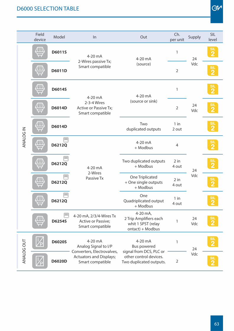
Fielddevice Model In Out Ch.
per unit Supply SIL level
AN
ALO
G IN
D6011S4-20 mA
2-Wires passive Tx;Smart compatible
4-20 mA(source)
1
24 Vdc
D6011D 2
D6014S
4-20 mA2-3-4 Wires
Active or Passive Tx;Smart compatible
4-20 mA(source or sink)
1
24 VdcD6014D 2
D6014DTwo
duplicated outputs1 in
2 out
D6212Q
4-20 mA2-Wires
Passive Tx
4-20 mA+ Modbus 4
24 Vdc
D6212QTwo duplicated outputs
+ Modbus2 in
4 out
D6212Q
One Triplicated + One single outputs
+ Modbus
2 in 4 out
D6212Q
One Quadriplicated output
+ Modbus
1 in 4 out
D6254S
4-20 mA, 2/3/4-Wires TxActive or Passive;Smart compatible
4-20 mA, 2 Trip Amplifi ers each
whit 1 SPST (relay ontact) + Modbus
1 24 Vdc
AN
ALO
G O
UT
D6020S 4-20 mAAnalog Signal to I/P
Converters, Electrovalves,Actuators and Displays;
Smart compatible
4-20 mABus powered
signal from DCS, PLC or other control devices.
Two duplicated outputs.
1
24 Vdc
D6020D 2
D6000 SELECTION TABLE
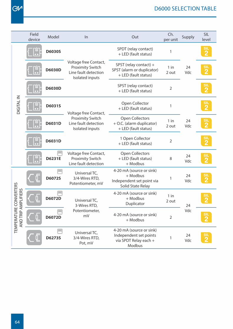
64
D6000 SELECTION TABLE
Fielddevice Model In Out Ch.
per unit Supply SIL level
DIG
ITA
L IN
D6030S
Voltage free Contact,Proximity Switch
Line fault detectionIsolated inputs
SPDT (relay contact)+ LED (fault status) 1
24VdcD6030D
SPST (relay contact) +SPST (alarm or duplicator)
+ LED (fault status)
1 in 2 out
D6030DSPST (relay contact)+ LED (fault status) 2
D6031S
Voltage free Contact,Proximity Switch
Line fault detectionIsolated inputs
Open Collector + LED (fault status) 1
24 VdcD6031D
Open Collectors+ O.C. (alarm duplicator)
+ LED (fault status)
1 in 2 out
D6031D1 Open Collector
+ LED (fault status) 2
D6231E
Voltage free Contact,Proximity Switch
Line fault detection
Open Collectors+ LED (fault status)
+ Modbus8 24
Vdc
TEM
PERA
TURE
CO
NVE
RTER
SA
ND
TRI
P A
MPL
IFIE
RS
D6072S
Universal TC, 3/4-Wires RTD,
Potentiometer, mV
4-20 mA (source or sink) + Modbus
Independent set point viaSolid State Relay
1 24Vdc
D6072D Universal TC, 3-Wires RTD,
Potentiometer, mV
4-20 mA (source or sink) + ModbusDuplicator
1 in2 out
24 Vdc
D6072D4-20 mA (source or sink)
+ Modbus 2
D6273S
Universal TC, 3/4-Wires RTD,
Pot, mV
4-20 mA (source or sink) Independent set points via SPDT Relay each +
Modbus
1 24 Vdc
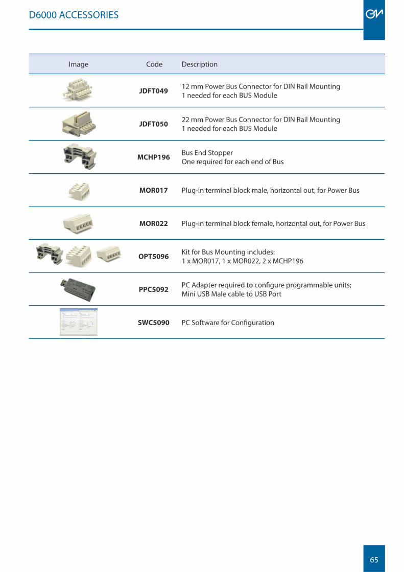
65
Image Code Description
JDFT04912 mm Power Bus Connector for DIN Rail Mounting1 needed for each BUS Module
JDFT05022 mm Power Bus Connector for DIN Rail Mounting1 needed for each BUS Module
MCHP196Bus End StopperOne required for each end of Bus
MOR017 Plug-in terminal block male, horizontal out, for Power Bus
MOR022 Plug-in terminal block female, horizontal out, for Power Bus
OPT5096Kit for Bus Mounting includes: 1 x MOR017, 1 x MOR022, 2 x MCHP196
PPC5092PC Adapter required to confi gure programmable units; Mini USB Male cable to USB Port
SWC5090 PC Software for Confi guration
D6000 ACCESSORIES

66
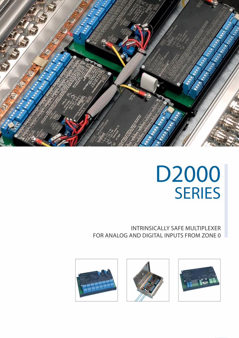
67
D2000 SERIES
D2000 SERIES
INTRINSICALLY SAFE MULTIPLEXERFOR ANALOG AND DIGITAL INPUTS FROM ZONE 0
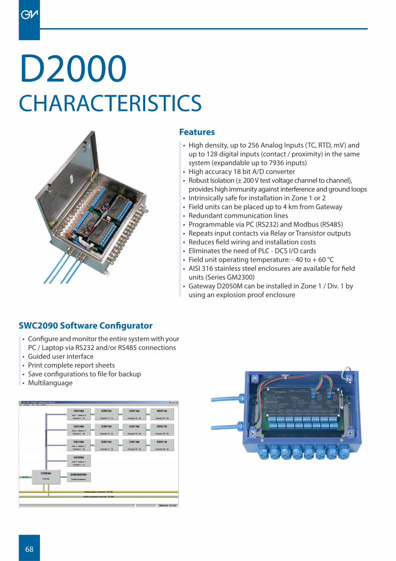
68
D2000Features
• High density, up to 256 Analog Inputs (TC, RTD, mV) and up to 128 digital inputs (contact / proximity) in the same system (expandable up to 7936 inputs)
• High accuracy 18 bit A/D converter• Robust Isolation (± 200 V test voltage channel to channel),
provides high immunity against interference and ground loops• Intrinsically safe for installation in Zone 1 or 2• Field units can be placed up to 4 km from Gateway• Redundant communication lines• Programmable via PC (RS232) and Modbus (RS485)• Repeats input contacts via Relay or Transistor outputs• Reduces fi eld wiring and installation costs• Eliminates the need of PLC - DCS I/O cards• Field unit operating temperature: - 40 to + 60 °C• AISI 316 stainless steel enclosures are available for fi eld
units (Series GM2300)• Gateway D2050M can be installed in Zone 1 / Div. 1 by
using an explosion proof enclosure
CHARACTERISTICS
SWC2090 Software Confi gurator
• Confi gure and monitor the entire system with your PC / Laptop via RS232 and/or RS485 connections
• Guided user interface• Print complete report sheets• Save confi gurations to fi le for backup• Multilanguage
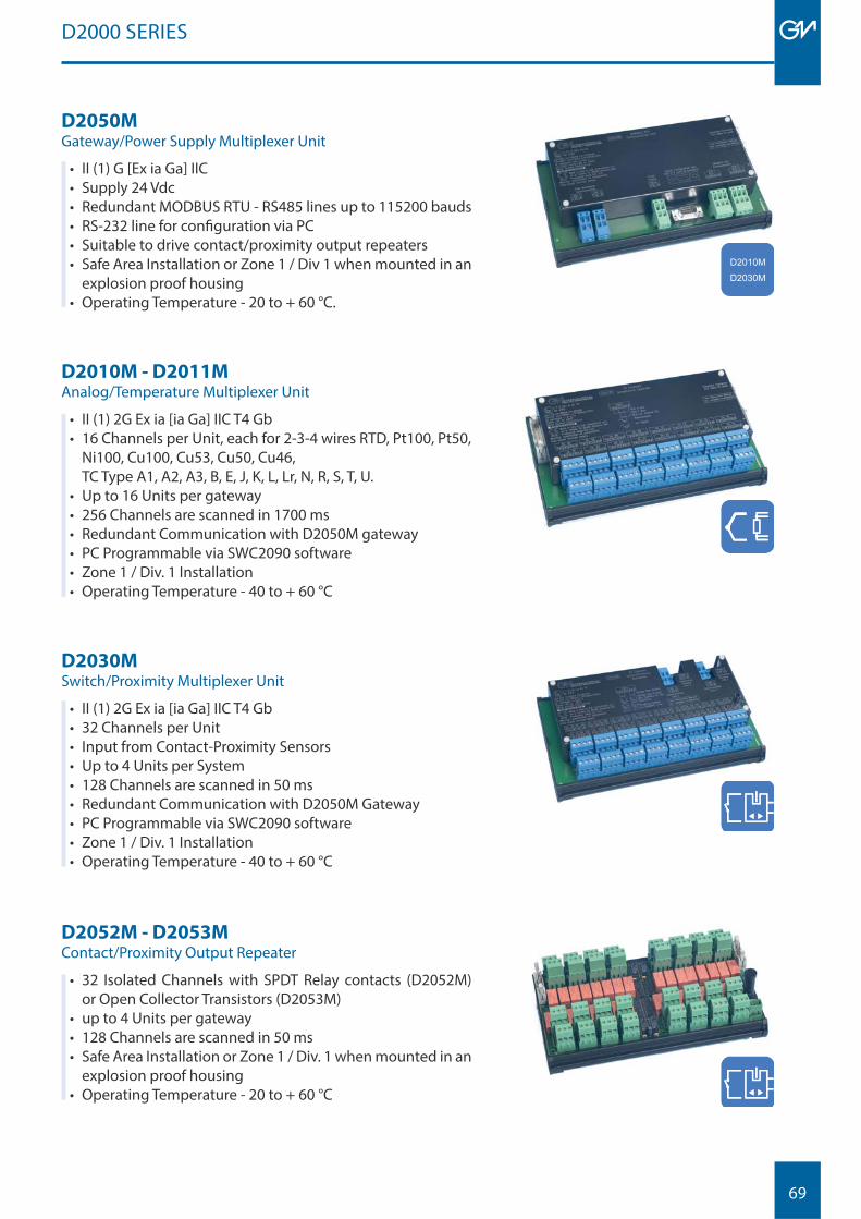
69
D2010M - D2011MAnalog/Temperature Multiplexer Unit
• II (1) 2G Ex ia [ia Ga] IIC T4 Gb• 16 Channels per Unit, each for 2-3-4 wires RTD, Pt100, Pt50,
Ni100, Cu100, Cu53, Cu50, Cu46, TC Type A1, A2, A3, B, E, J, K, L, Lr, N, R, S, T, U.
• Up to 16 Units per gateway• 256 Channels are scanned in 1700 ms• Redundant Communication with D2050M gateway• PC Programmable via SWC2090 software• Zone 1 / Div. 1 Installation• Operating Temperature - 40 to + 60 °C
D2030MSwitch/Proximity Multiplexer Unit
• II (1) 2G Ex ia [ia Ga] IIC T4 Gb• 32 Channels per Unit• Input from Contact-Proximity Sensors• Up to 4 Units per System• 128 Channels are scanned in 50 ms• Redundant Communication with D2050M Gateway• PC Programmable via SWC2090 software• Zone 1 / Div. 1 Installation• Operating Temperature - 40 to + 60 °C
D2050MGateway/Power Supply Multiplexer Unit
• II (1) G [Ex ia Ga] IIC• Supply 24 Vdc• Redundant MODBUS RTU - RS485 lines up to 115200 bauds• RS-232 line for confi guration via PC• Suitable to drive contact/proximity output repeaters• Safe Area Installation or Zone 1 / Div 1 when mounted in an
explosion proof housing• Operating Temperature - 20 to + 60 °C.
D2052M - D2053MContact/Proximity Output Repeater
• 32 Isolated Channels with SPDT Relay contacts (D2052M)or Open Collector Transistors (D2053M)
• up to 4 Units per gateway• 128 Channels are scanned in 50 ms• Safe Area Installation or Zone 1 / Div. 1 when mounted in an
explosion proof housing• Operating Temperature - 20 to + 60 °C
D2000 SERIES
D2010MD2030M
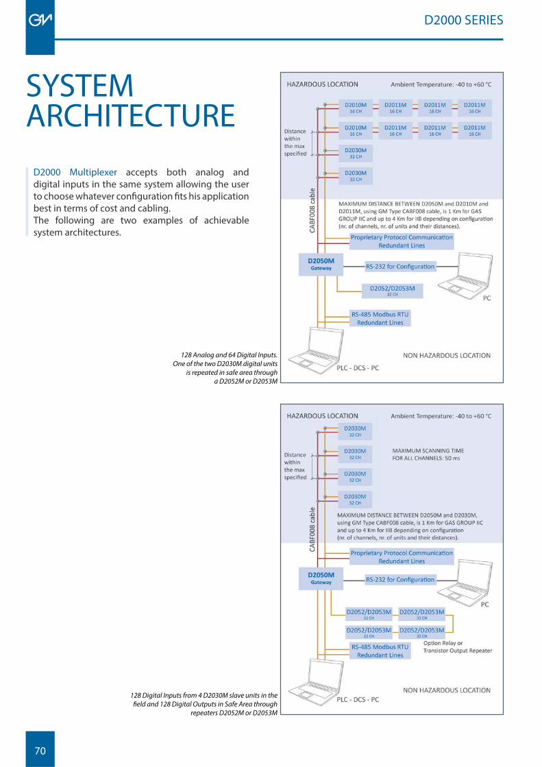
70
SYSTEMARCHITECTURE
D2000 SERIES
D2000 Multiplexer accepts both analog and digital inputs in the same system allowing the user to choose whatever confi guration fi ts his application best in terms of cost and cabling.The following are two examples of achievable system architectures.
128 Analog and 64 Digital Inputs.One of the two D2030M digital units
is repeated in safe area through a D2052M or D2053M
128 Digital Inputs from 4 D2030M slave units in the fi eld and 128 Digital Outputs in Safe Area through
repeaters D2052M or D2053M
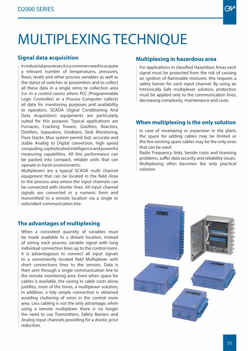
71
D2000 SERIES
MULTIPLEXING TECHNIQUESignal data acquisition
In industrial processes it is a common need to acquire a relevant number of temperatures, pressures, fl ows, levels and other process variables as well as the status of switches or proximitors and to collect all these data in a single remo te collection area (i.e. in a control room) where PLC (Programmable Logic Controller) or a Process Computer collects all data for monitoring purposes and availability to operators. SCADA (Signal Conditioning And Data Acquisition) equipments are particularly suited for this purpose. Typical applications are Furnaces, Cracking Towers, Gasifi ers, Reactors, Distillers, Separators, Oxidizers, Tank Monitoring, Flare Stacks. Mux system permit fast, accurate and stable Analog to Digital conversion, high speed computing, sophisticated intelligence and powerful measuring capabilities. All this performance can be packed into compact, reliable units that can operate in harsh environments.Multiplexers are a typical SCADA multi channel equipment that can be located in the fi eld close to the process area where the input channels can be connected with shorter lines. All input channel signals are converted in a numeric form and transmitted to a remote location via a single or redundant communication line.
The advantages of multiplexing
When a consistent quantity of variables must be made available to a distant location, instead of wiring each process variable signal with long individual connection lines up to the control room, it is advantageous to connect all input signals to a conveniently located fi eld Multiplexer with short connections lines to the sensors. Data is then sent through a single communication line to the remote monitoring area. Even when space for cables is available, the saving in cable costs alone justifi es, most of the times, a multiplexer solution; in addition, a tidy simple connection is obtained avoiding cluttering of wires in the control room area. Less cabling is not the only advantage; when using a remote multiplexer there is no longer the need to use Transmitters, Safety Barriers and Analog Input channels providing for a drastic price reduction.
Multiplexing in hazardous area
For applications in classifi ed Hazardous Areas each signal must be protected from the risk of causing an ignition of fl ammable mixtures: this requires a safety barrier for each input channel. By using an Intrinsically Safe multiplexer solution, protection must be applied only to the communication lines, decreasing complexity, maintenance and costs.
When multiplexing is the only solution
In case of revamping or expansion in the plant, the space for adding cables may be limited or the few existing spare cables may be the only ones that can be used. Radio Frequency links, beside costs and licensing problems, suff er data security and reliability issues. Multiplexing often becomes the only practical solution.
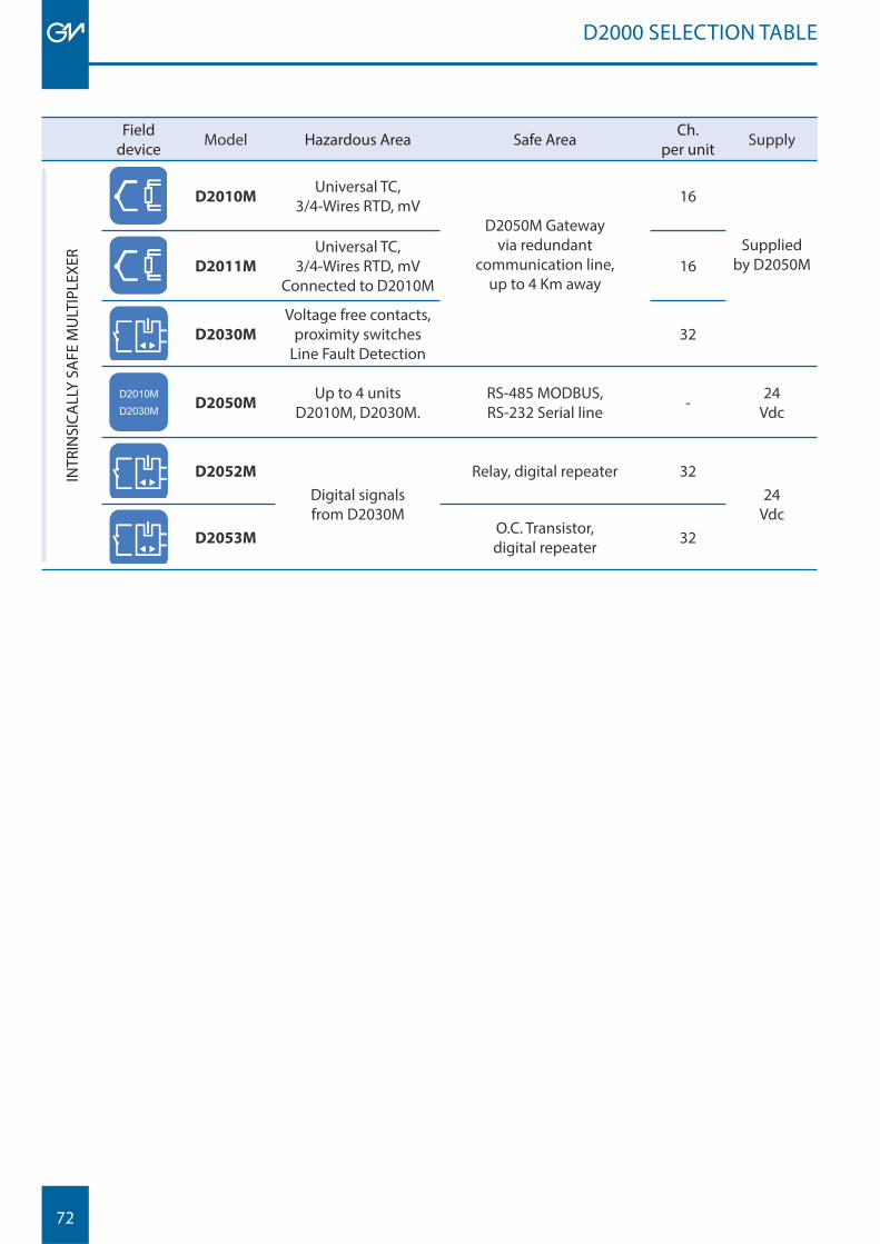
72
Fielddevice Model Hazardous Area Safe Area Ch.
per unit Supply
INTR
INSI
CALL
Y SA
FE M
ULT
IPLE
XER
D2010MUniversal TC,
3/4-Wires RTD, mVD2050M Gateway
via redundant communication line,
up to 4 Km away
16
Supplied by D2050M D2011M
Universal TC, 3/4-Wires RTD, mV
Connected to D2010M16
D2030M
Voltage free contacts, proximity switches
Line Fault Detection32
D2010MD2030M D2050M
Up to 4 units D2010M, D2030M.
RS-485 MODBUS,RS-232 Serial line - 24
Vdc
D2052M
Digital signalsfrom D2030M
Relay, digital repeater 3224
Vdc D2053M
O.C. Transistor,digital repeater 32
D2000 SELECTION TABLE
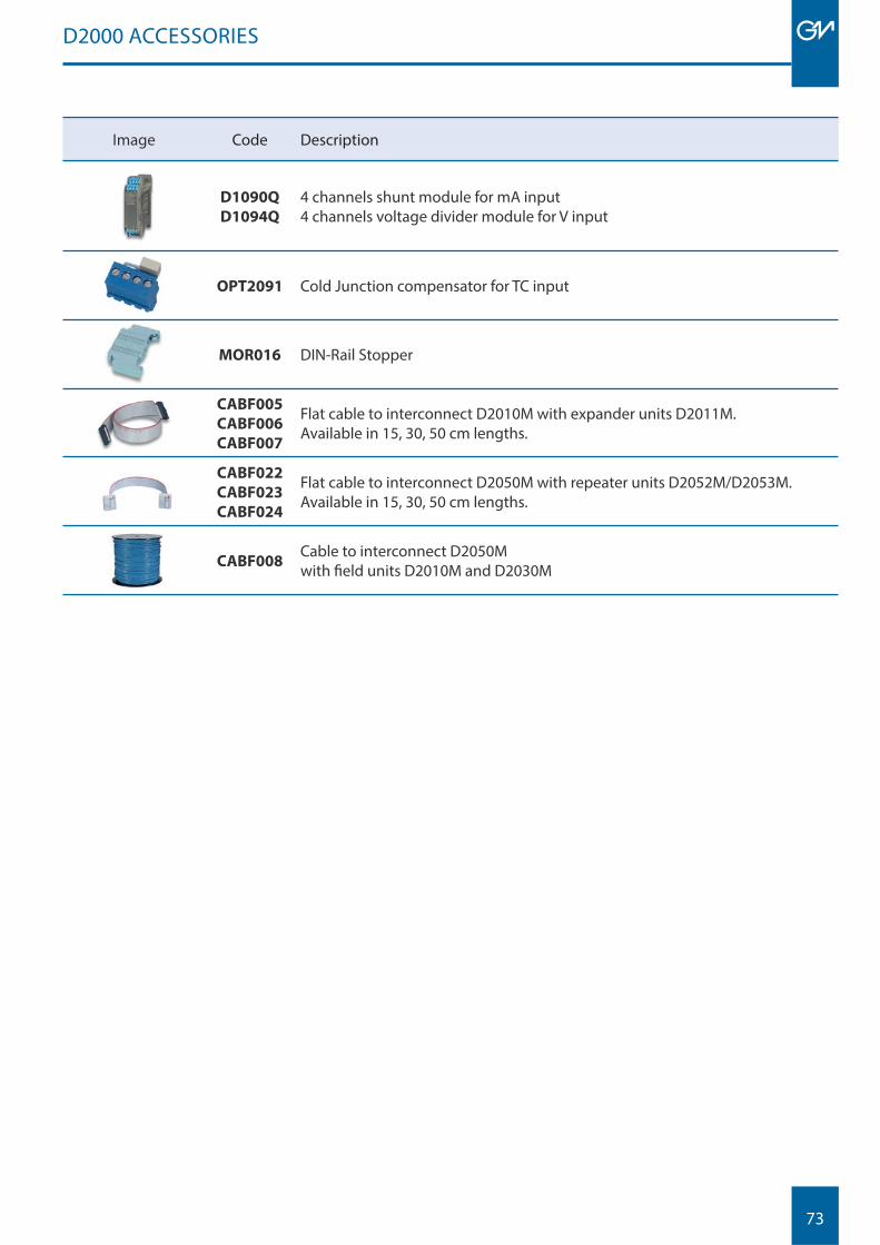
73
Image Code Description
D1090Q
D1094Q
4 channels shunt module for mA input4 channels voltage divider module for V input
OPT2091 Cold Junction compensator for TC input
MOR016 DIN-Rail Stopper
CABF005
CABF006
CABF007
Flat cable to interconnect D2010M with expander units D2011M.Available in 15, 30, 50 cm lengths.
CABF022
CABF023
CABF024
Flat cable to interconnect D2050M with repeater units D2052M/D2053M.Available in 15, 30, 50 cm lengths.
CABF008Cable to interconnect D2050M with fi eld units D2010M and D2030M
D2000 ACCESSORIES

74
75
POWER SUPPLIES
INTRINSICALLY SAFE AND NON-INCENDIVE POWER SUPPLIES
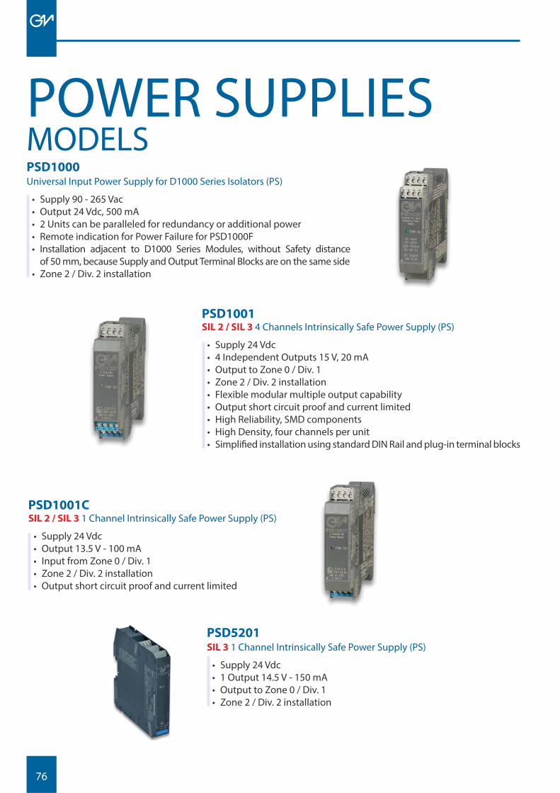
76
POWER SUPPLIESMODELSPSD1000 Universal Input Power Supply for D1000 Series Isolators (PS)
• Supply 90 - 265 Vac• Output 24 Vdc, 500 mA• 2 Units can be paralleled for redundancy or additional power• Remote indication for Power Failure for PSD1000F• Installation adjacent to D1000 Series Modules, without Safety distance
of 50 mm, because Supply and Output Terminal Blocks are on the same side• Zone 2 / Div. 2 installation
PSD1001SIL 2 / SIL 3 4 Channels Intrinsically Safe Power Supply (PS)
• Supply 24 Vdc• 4 Independent Outputs 15 V, 20 mA• Output to Zone 0 / Div. 1• Zone 2 / Div. 2 installation• Flexible modular multiple output capability• Output short circuit proof and current limited• High Reliability, SMD components• High Density, four channels per unit• Simplifi ed installation using standard DIN Rail and plug-in terminal blocks
PSD1001CSIL 2 / SIL 3 1 Channel Intrinsically Safe Power Supply (PS)
• Supply 24 Vdc• Output 13.5 V - 100 mA• Input from Zone 0 / Div. 1• Zone 2 / Div. 2 installation• Output short circuit proof and current limited
PSD5201SIL 3 1 Channel Intrinsically Safe Power Supply (PS)
• Supply 24 Vdc• 1 Output 14.5 V - 150 mA • Output to Zone 0 / Div. 1• Zone 2 / Div. 2 installation
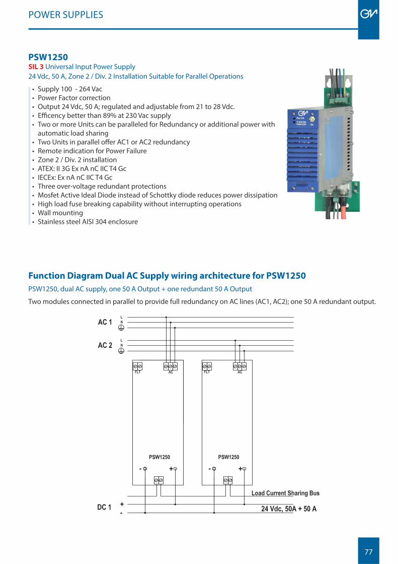
77
POWER SUPPLIES
PSW1250SIL 3 Universal Input Power Supply24 Vdc, 50 A, Zone 2 / Div. 2 Installation Suitable for Parallel Operations
• Supply 100 - 264 Vac• Power Factor correction• Output 24 Vdc, 50 A; regulated and adjustable from 21 to 28 Vdc.• Effi cency better than 89% at 230 Vac supply• Two or more Units can be paralleled for Redundancy or additional power with
automatic load sharing• Two Units in parallel off er AC1 or AC2 redundancy• Remote indication for Power Failure• Zone 2 / Div. 2 installation• ATEX: II 3G Ex nA nC IIC T4 Gc• IECEx: Ex nA nC IIC T4 Gc• Three over-voltage redundant protections• Mosfet Active Ideal Diode instead of Schottky diode reduces power dissipation• High load fuse breaking capability without interrupting operations• Wall mounting• Stainless steel AISI 304 enclosure
Function Diagram Dual AC Supply wiring architecture for PSW1250
PSW1250, dual AC supply, one 50 A Output + one redundant 50 A Output
Two modules connected in parallel to provide full redundancy on AC lines (AC1, AC2); one 50 A redundant output.
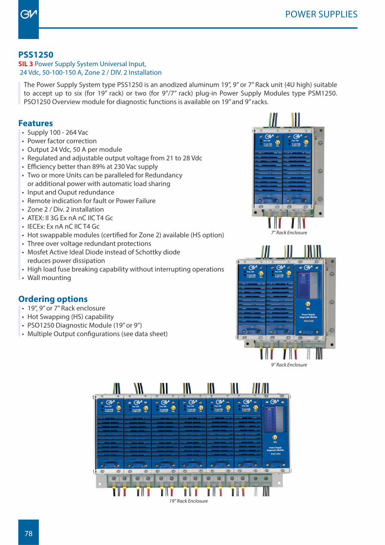
78
PSS1250 SIL 3 Power Supply System Universal Input, 24 Vdc, 50-100-150 A, Zone 2 / DIV. 2 Installation
The Power Supply System type PSS1250 is an anodized aluminum 19”, 9” or 7” Rack unit (4U high) suitable to accept up to six (for 19” rack) or two (for 9”/7” rack) plug-in Power Supply Modules type PSM1250.PSO1250 Overview module for diagnostic functions is available on 19” and 9” racks.
Ordering options• 19”, 9” or 7” Rack enclosure• Hot Swapping (HS) capability • PSO1250 Diagnostic Module (19” or 9”)• Multiple Output confi gurations (see data sheet)
9” Rack Enclosure
19” Rack Enclosure
POWER SUPPLIES
Features• Supply 100 - 264 Vac• Power factor correction• Output 24 Vdc, 50 A per module• Regulated and adjustable output voltage from 21 to 28 Vdc• Effi ciency better than 89% at 230 Vac supply• Two or more Units can be paralleled for Redundancy
or additional power with automatic load sharing• Input and Ouput redundance• Remote indication for fault or Power Failure• Zone 2 / Div. 2 installation• ATEX: II 3G Ex nA nC IIC T4 Gc• IECEx: Ex nA nC IIC T4 Gc• Hot swappable modules (certifi ed for Zone 2) available (HS option)• Three over voltage redundant protections• Mosfet Active Ideal Diode instead of Schottky diode
reduces power dissipation• High load fuse breaking capability without interrupting operations• Wall mounting
7” Rack Enclosure
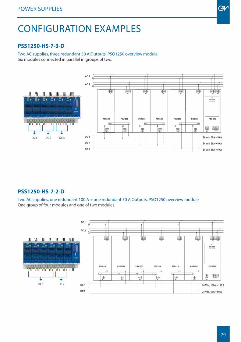
79
PSS1250-HS-7-3-D
Two AC supplies, three redundant 50 A Outputs, PSO1250 overview module Six modules connected in parallel in groups of two.
POWER SUPPLIES
CONFIGURATION EXAMPLES
PSS1250-HS-7-2-D
Two AC supplies, one redundant 100 A + one redundant 50 A Outputs, PSO1250 overview moduleOne group of four modules and one of two modules.
DC2 DC3DC1
DC2DC1
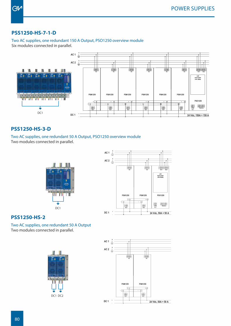
80
PSS1250-HS-3-D
Two AC supplies, one redundant 50 A Output, PSO1250 overview module Two modules connected in parallel.
POWER SUPPLIES
PSS1250-HS-2
Two AC supplies, one redundant 50 A OutputTwo modules connected in parallel.
DC1
DC1 DC2
PSS1250-HS-7-1-D
Two AC supplies, one redundant 150 A Output, PSO1250 overview moduleSix modules connected in parallel.
DC1
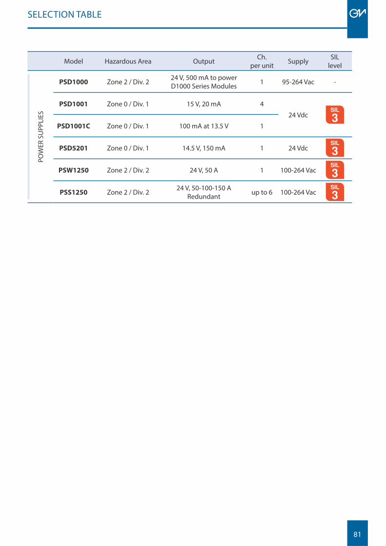
81
Model Hazardous Area Output Ch.per unit Supply SIL
level
POW
ER S
UPP
LIES
PSD1000 Zone 2 / Div. 2 24 V, 500 mA to power D1000 Series Modules 1 95-264 Vac -
PSD1001 Zone 0 / Div. 1 15 V, 20 mA 4
24 Vdc MODBUS
PSD1001C Zone 0 / Div. 1 100 mA at 13.5 V 1
PSD5201 Zone 0 / Div. 1 14.5 V, 150 mA 1 24 Vdc MODBUS
PSW1250 Zone 2 / Div. 2 24 V, 50 A 1 100-264 Vac MODBUS
PSS1250 Zone 2 / Div. 2 24 V, 50-100-150 ARedundant up to 6 100-264 Vac MODBUS
SELECTION TABLE

82
83
T3010 SERIES
D9000SERIES
SURGE PROTECTORS
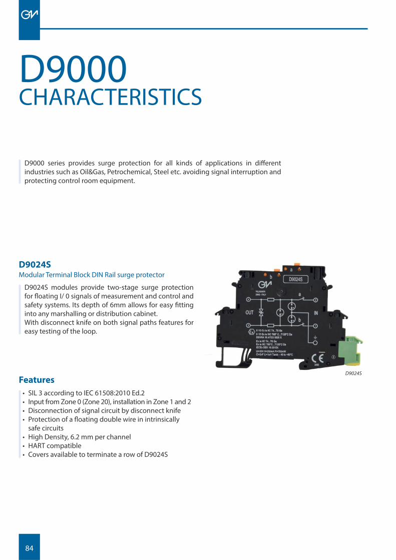
84
CHARACTERISTICSD9000
D9000 series provides surge protection for all kinds of applications in diff erent industries such as Oil&Gas, Petrochemical, Steel etc. avoiding signal interruption and protecting control room equipment.
D9024SModular Terminal Block DIN Rail surge protector
D9024S modules provide two-stage surge protection for fl oating I/ 0 signals of measurement and control and safety systems. Its depth of 6mm allows for easy fi tting into any marshalling or distribution cabinet.With disconnect knife on both signal paths features for easy testing of the loop.
D9024SFeatures
• SIL 3 according to IEC 61508:2010 Ed.2• Input from Zone 0 (Zone 20), installation in Zone 1 and 2• Disconnection of signal circuit by disconnect knife• Protection of a fl oating double wire in intrinsically
safe circuits• High Density, 6.2 mm per channel• HART compatible• Covers available to terminate a row of D9024S
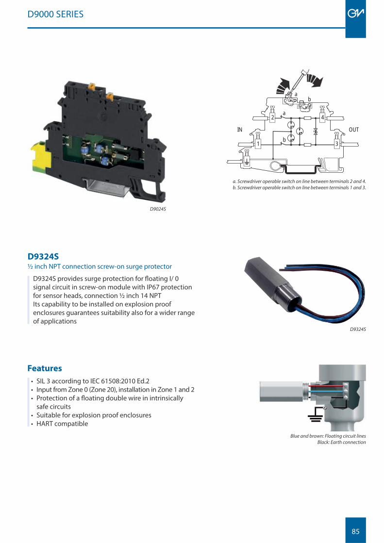
85
Features
• SIL 3 according to IEC 61508:2010 Ed.2• Input from Zone 0 (Zone 20), installation in Zone 1 and 2• Protection of a fl oating double wire in intrinsically
safe circuits• Suitable for explosion proof enclosures• HART compatible
D9000 SERIES
D9324S½ inch NPT connection screw-on surge protector
D9324S provides surge protection for fl oating I/ 0 signal circuit in screw-on module with IP67 protection for sensor heads, connection ½ inch 14 NPTIts capability to be installed on explosion proof enclosures guarantees suitability also for a wider range of applications
D9324S
Blue and brown: Floating circuit linesBlack: Earth connection
a b
b
a 2
1
4
3
TUO NI
a. Screwdriver operable switch on line between terminals 2 and 4.b. Screwdriver operable switch on line between terminals 1 and 3.
D9024S

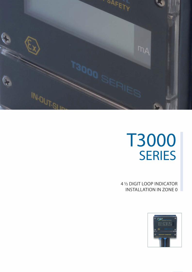
87
T3010 SERIES
T3000SERIES
4 ½ DIGIT LOOP INDICATOR INSTALLATION IN ZONE 0
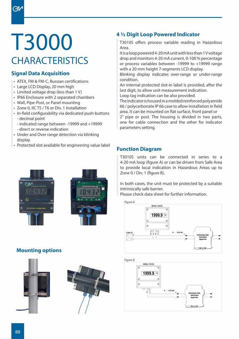
88
Signal Data Acquisition
• ATEX, FM & FM-C, Russian certifi cations• Large LCD Display, 20 mm high• Limited voltage drop (less than 1 V)• IP66 Enclosure with 2 separated chambers• Wall, Pipe-Post, or Panel mounting• Zone 0, IIC T5 / T6 or Div. 1 Installation• In-fi eld confi gurability via dedicated push-buttons
- decimal point- indicated range between -19999 and +19999- direct or reverse indication
• Under and Over range detection via blinking display
• Protected slot available for engineering value label
4 ½ Digit Loop Powered Indicator
T3010S off ers process variable reading in Hazardous Area. It is a loop powered 4-20 mA unit with less than 1 V voltage drop and monitors 4-20 mA current, 0-100 % percentage or process variables between -19999 to +19999 range with a 20 mm height 7-segments LCD display.Blinking display indicates over-range or under-range condition.An internal protected slot-in label is provided, after the last digit, to allow unit measurement indication. Loop tag indication can be also provided.The indicator is housed in a molded reinforced polyamide 66 / polycarbonate IP 66 case to allow installation in fi eld area. It can be mounted on fl at surface, front panel or 2” pipe or post. The housing is divided in two parts, one for cable connection and the other for indicator parameters setting.
CHARACTERISTICST3000
Function Diagram
T3010S units can be connected in series to a 4-20 mA loop (fi gure A) or can be driven from Safe Area to provide local indication in Hazardous Areas up to Zone 0 / Div. 1 (fi gure B).
In both cases, the unit must be protected by a suitable intrinsically safe barrier.Please check data sheet for further information.
Figure A
Figure B
Mounting options

89
IMMAGINE
90
Download
• Data Sheets• Instruction Manuals• Application Notes• Certifi cates• Software
News
• Latest products• New Certifi cations• Worldwide Exhibitions
Utilities
• Online tools for webmasters• Mailing List• I.S. Loop verifi cation tool• Product fi nder
Products
• Guided model fi nder• Series presentation• Model details• Advanced search
Contacts
• Agents and Distributors• Quotation request form• Technical and Commercial contacts
A wide range of services and information can be found online at www.gmintsrl.com
GMINTSRL.COM
ONLINE INFORMATION

Data specifi ed in this document are merely descriptive of the products and should be integrated with relevant technical specifi cations. Our products are constantly being further developed and the information presented herein refers to the latest's product release. No statements concerning a certain condition or suitability for a certain application can be derived from our information. The information given does not release the user from the obligation of own judgment and verifi cation. Terms & Conditions can be found at www.gmintsrl.com.