Embed Size (px)
Citation preview
This short manual is meant to give an exploratory overview of the essential functions of the corpuls3.Reading this short manual is no substitute neither for the necessity to carefully read through the user manual nor for the instruction and training on the device by an authorised medical products consultant.
Short Manual
2 ENG - Version 2.2 - P/N 04131.02
Charging the Battery
Charging compact device via charging bracket
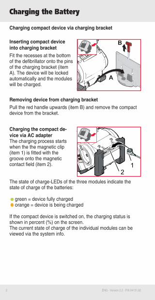
Inserting compact device into charging bracketFit the recesses at the bottom of the defibrillator onto the pins of the charging bracket (item A). The device will be locked automatically and the modules will be charged.
Removing device from charging bracketPull the red handle upwards (item B) and remove the compact device from the bracket.
Charging the compact de-vice via AC adapterThe charging process starts when the the magnetic clip (item 1) is fitted with the groove onto the magnetic contact field (item 2).
The state of charge-LEDs of the three modules indicate the state of charge of the batteries:
green = device fully chargedorange = device is being charged
If the compact device is switched on, the charging status is shown in percent (%) on the screen. The current state of charge of the individual modules can be viewed via the system info.
21
B
A
3ENG - Version 2.2 - P/N 04131.02
Switching On and Off
Switching the Compact Device On and Off
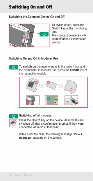
To switch on/off, press the On/Off key at the monitoring unit.The compact device is swit-ched off after a confirmation prompt.
Switching On and Off in Modular Use
To switch on the monitoring unit, the patient box and the defibrillator in modular use, press the On/Off key at the respective module.
Switching off all modules:Press the On/Off key on the device. All modules are switched off after a confirmation prompt, if they were connected via radio at that point.
If this is not the case, the warning message "Check modules" appears on the screen.
4 ENG - Version 2.2 - P/N 04131.02
Printer and Printing
Note
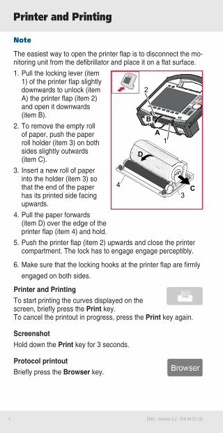
The easiest way to open the printer flap is to disconnect the mo-nitoring unit from the defibrillator and place it on a flat surface.1. Pull the locking lever (item
1) of the printer flap slightly downwards to unlock (item A) the printer flap (item 2) and open it downwards (item B).
2. To remove the empty roll of paper, push the paper roll holder (item 3) on both sides slightly outwards (item C).
3. Insert a new roll of paper into the holder (item 3) so that the end of the paper has its printed side facing upwards.
4. Pull the paper forwards (item D) over the edge of the printer flap (item 4) and hold.
5. Push the printer flap (item 2) upwards and close the printer compartment. The lock has to engage engage perceptibly.
6. Make sure that the locking hooks at the printer flap are firmly engaged on both sides.
Printer and PrintingTo start printing the curves displayed on the screen, briefly press the Print key.To cancel the printout in progress, press the Print key again.
ScreenshotHold down the Print key for 3 seconds.
Protocol printoutBriefly press the Browser key.
34 C
D
1A
2
B
5ENG - Version 2.2 - P/N 04131.02
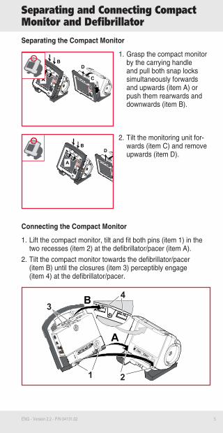
Separating the Compact Monitor
1. Grasp the compact monitor by the carrying handle and pull both snap locks simultaneously forwards and upwards (item A) or push them rearwards and downwards (item B).
2. Tilt the monitoring unit for-wards (item C) and remove upwards (item D).
Connecting the Compact Monitor
1. Lift the compact monitor, tilt and fit both pins (item 1) in the two recesses (item 2) at the defibrillator/pacer (item A).
2. Tilt the compact monitor towards the defibrillator/pacer (item B) until the closures (item 3) perceptibly engage (item 4) at the defibrillator/pacer.
Separating and Connecting Compact Monitor and Defibrillator
A
B
C
D
A
B
C
D
1 2
34
6 ENG - Version 2.2 - P/N 04131.02
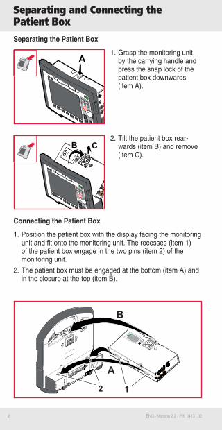
Separating and Connecting the Patient BoxSeparating the Patient Box
1. Grasp the monitoring unit by the carrying handle and press the snap lock of the patient box downwards (item A).
2. Tilt the patient box rear-wards (item B) and remove (item C).
Connecting the Patient Box
1. Position the patient box with the display facing the monitoring unit and fit onto the monitoring unit. The recesses (item 1) of the patient box engage in the two pins (item 2) of the monitoring unit.
2. The patient box must be engaged at the bottom (item A) and in the closure at the top (item B).
B
A
12
A
CB
7ENG - Version 2.2 - P/N 04131.02
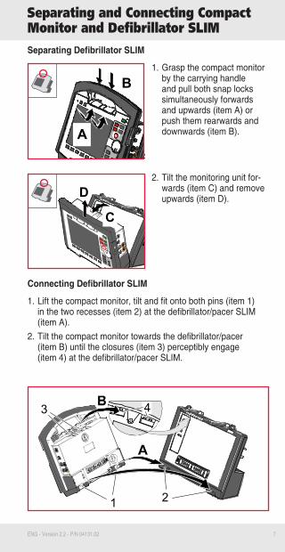
Separating and Connecting Compact Monitor and Defibrillator SLIMSeparating Defibrillator SLIM
1. Grasp the compact monitor by the carrying handle and pull both snap locks simultaneously forwards and upwards (item A) or push them rearwards and downwards (item B).
2. Tilt the monitoring unit for-wards (item C) and remove upwards (item D).
Connecting Defibrillator SLIM
1. Lift the compact monitor, tilt and fit onto both pins (item 1) in the two recesses (item 2) at the defibrillator/pacer SLIM (item A).
2. Tilt the compact monitor towards the defibrillator/pacer (item B) until the closures (item 3) perceptibly engage (item 4) at the defibrillator/pacer SLIM.
D
C
A
B
1 2
3 4

8 ENG - Version 2.2 - P/N 04131.02
Radio Connection Patient Box
In case of malfunctions of the radio connection, take the following measures:
The distance between the modules is not greater than 10 meters.1. The antenna of the radio unit is located at the top of the
patient box (see symbol). To enable an optimal connection, choose a position for the patient box that allows unimpeded view to the other modules.
2. Make sure that the antenna in the patient box is not shado-wed by metallic or metallised objects.
3. If a radio connection is not possible, connect the modules mechanically.
4. For further instructions see the User Manual.
NoteAll data are saved in the patient box. An interruption of the radio connection does not cause loss of monitoring data.
Pairing/Ad-hoc ConnectionFor a pairing the hardware version of the radio modules and
the software version have to be identical. Modules with different radio modules (see number symbol) can nevertheless have a mechanical ad-hoc connection.
WARNING: If two modules connected by an ad-hoc con-nection are separated, the device attempts automatically to re-establish the radio connection to the original patient box and defibrillator/pacer.
CAUTION: During an ad-hoc connection a wireless con-nection to other modules is not possible.
2

9ENG - Version 2.2 - P/N 04131.02
Manual Defibrillation/Cardioversion
Defibrillation/Cardioversion with corPatch Therapy Electrodes
Attach the corPatch therapy electrodes to the thorax of the patient as shown on the packa-ge and connect to the therapy master cable, if necessary.
1. Press the Manual key (item 1) for a quick boot-up in manual defibrillation mode.
2. Select the required energy level with the jog dial or via the softkeys.
3. Press the Charge key (item 2) to start the charging process.
4. To perform defibrillation or cardioversi-on, hold down the Shock key (item 3) until the shock has been delivered.
Defibrillation/Cardioversion with Shock Paddles
1. Press the Manual key for a quick boot-up in manual defibrillation mode.
2. Select the required energy level with the jog dial or via the softkeys.
3. Apply sufficient electrode gel onto the surface of the shock paddles and place them on the patient’s thorax.
4. To start the charging process, briefly press one of the shock paddle buttons.
5. To perform defibrillation or cardioversi-on, press both shock paddle buttons simultaneously and hold down until shock has been delivered.
10 ENG - Version 2.2 - P/N 04131.02
Defibrillation in the AED Mode
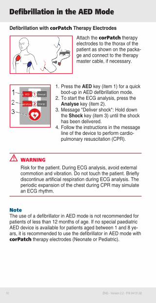
Defibrillation with corPatch Therapy Electrodes
Attach the corPatch therapy electrodes to the thorax of the patient as shown on the packa-ge and connect to the therapy master cable, if necessary.
1. Press the AED key (item 1) for a quick boot-up in AED defibrillation mode.
2. To start the ECG analysis, press the Analyse key (item 2).
3. Message "Deliver shock": Hold down the Shock key (item 3) until the shock has been delivered.
4. Follow the instructions in the message line of the device to perform cardio-pulmonary resuscitation (CPR).
WARNINGRisk for the patient. During ECG analysis, avoid external commotion and vibration. Do not touch the patient. Briefly discontinue artificial respiration during ECG analysis. The periodic expansion of the chest during CPR may simulate an ECG rhythm.
NoteThe use of a defibrillator in AED mode is not recommended for patients of less than 12 months of age. If no special paediatric AED device is available for patients aged between 1 and 8 ye-ars, it is recommended to use the defibrillator in AED mode with corPatch therapy electrodes (Neonate or Pediatric).

11ENG - Version 2.2 - P/N 04131.02
corPatch CPR
CPR Feedback
If a corPatch CPR sensor is used, the rate and depth of a thorax compression can be measured. Speech- and text mes-sages like "Push harder" or "Good compressions" inform the user of the quality of the thorax compressions. "Fully release" reminds the user to release the thorax.
Connect the corPatch CPR sensor to the thorax of the patient and to the intermediate cable leading to the patient box as shown on the package.
WARNINGDuring the phase between compressions, the user has to make sure that the pressure is completely relieved from the thorax. Otherwise, there can be false-negative feedback.
Metronome
The metronome supports the resuscitation acoustically. It emits a tone sequence which signals ventilations and thorax compres-sions to the user. To start the metronome in AED- or manual defibrillation mode, press the softkey [Metronome].
WARNINGThe metronome pauses at reaching readiness for shock in AED or manual defibrillation mode.After the shock has been released or 10 secs after readi-ness for shock without releasing the shock, the metrono-me resumes signalling the compression tone.
12 ENG - Version 2.2 - P/N 04131.02
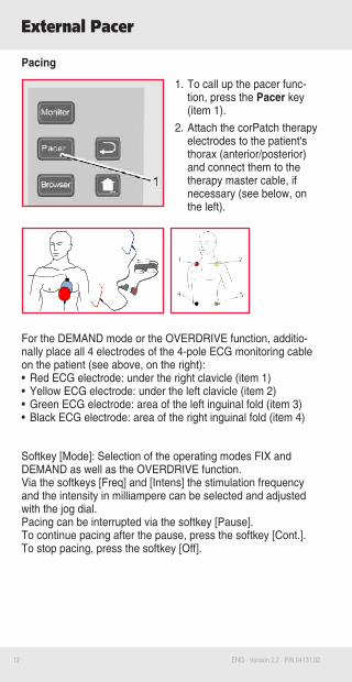
Pacing
1. To call up the pacer func-tion, press the Pacer key (item 1).
2. Attach the corPatch therapy electrodes to the patient's thorax (anterior/posterior) and connect them to the therapy master cable, if necessary (see below, on the left).
For the DEMAND mode or the OVERDRIVE function, additio-nally place all 4 electrodes of the 4-pole ECG monitoring cable on the patient (see above, on the right):• Red ECG electrode: under the right clavicle (item 1)• Yellow ECG electrode: under the left clavicle (item 2)• Green ECG electrode: area of the left inguinal fold (item 3)• Black ECG electrode: area of the right inguinal fold (item 4)
Softkey [Mode]: Selection of the operating modes FIX and DEMAND as well as the OVERDRIVE function.Via the softkeys [Freq] and [Intens] the stimulation frequency and the intensity in milliampere can be selected and adjusted with the jog dial.Pacing can be interrupted via the softkey [Pause].To continue pacing after the pause, press the softkey [Cont.].To stop pacing, press the softkey [Off].
External Pacer

13ENG - Version 2.2 - P/N 04131.02
Diagnostic ECG
Diagnostic ECG
To monitor the heart rhythm and heart rate, place all 4 ECG electrodes of the 4-pole ECG monitoring cable on the patient:• Red ECG electrode: right arm (item 1)• Yellow ECG electrode: left arm (item 2)• Green ECG electrode: left leg (item 3)• Black ECG electrode: right leg (item 4)
For a full diagnostic ECG, additionally place all 6 ECG electrodes of the ECG diagnostic cable on the patient’s thorax:• Red V1 ECG electrode (item 1)• Yellow V2 ECG electrode (item 2)• Green V3 ECG electrode (item 3)• Brown V4 ECG electrode (item 4)• Black V5 ECG electrode (item 5)• Violet V6 ECG electrode (item 6)
Performing a Diagnostic ECG
1. Press the Monitor key.2. Softkey [D-ECG]: A preview of all ECG leads is
displayed on the screen.3. Message "Ready for D-ECG": Press the softkey [Start].
The displayed derivations are saved automatically.4. To print out the curves, press the softkey [Print].5. Softkey [Cancel]: Switch-over from preview to monitoring
mode.
Note If the signal quality of one or several leads is poor or missing, check electrode contact and electrode positioning.
WARNING: Changing the factory filter settings can affect the represen-tation of the ECG. As a consequence, wrong interpretation of the ECG is possible, which can result in inadequate treatment.
3
56
412
14 ENG - Version 2.2 - P/N 04131.02
If the curve fields or parameter fields of the connected measu-ring option are not displayed automatically, they have to be se-lected. Select via the main menu (jog dial "Signals" "Curves/Parameters") or via the parameter or curve context menu.
Parameter Context Menu and Curve Context MenuSelect the required parameter/curve field with the jog dial and confirm by pressing the jog dial.In the parameter context menu the type of parameter can be selected, the alarms of the respective parameter deactivated or the automatic limits "Auto Limits" activated.In the curve menu the type of curve can be selected, the sweep speed and the amplitude settings changed and in IBP mode the sensors can be calibrated and/or labelled. The softkey context menu allows a quick selection of menu items that are relevant for the respective softkey.
Oximetry (SpO2/PR/PI/SpCO/SpHb/SpMet/SpHb)Attach the oximetry sensor according to the manufacturer’s instructions to a finger/toe. Measurement starts automatically after the sensor has been attached. The measured values can be displayed as a plethysmogramme or as numerical values.
Capnometry (CO2/RR)Attach the CO2 sensor with an appropriate adapter to the pati-ent according to the manufacturer’s instructions. Measurement starts automatically after the sensor has been attached. The measured values can be displayed as a capnogramme or as numerical values.
TemperatureAttach the temperature sensor oesophageally or rectally or place it on the surface of the skin or into the ear. If necessary, use a protective cover. The measured values can be displayed as numerical values (T1/T2).
Trend curvesIn monitoring mode the trend curves can be called up via the softkey [Trend]. The trend curve is available for all vital parame-ters and is updated every minute. Trend curves can be printed out. Press softkey [Curves] to return to monitoring mode.
Monitoring Vital Parameters
15ENG - Version 2.2 - P/N 04131.02
ECG Monitoring
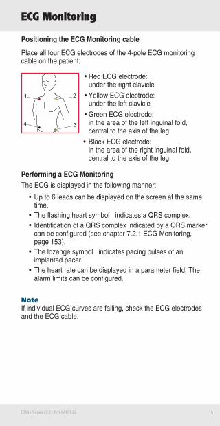
Positioning the ECG Monitoring cable
Place all four ECG electrodes of the 4-pole ECG monitoring cable on the patient:
• Red ECG electrode: under the right clavicle
• Yellow ECG electrode: under the left clavicle
• Green ECG electrode: in the area of the left inguinal fold, central to the axis of the leg
• Black ECG electrode: in the area of the right inguinal fold, central to the axis of the leg
Performing a ECG MonitoringThe ECG is displayed in the following manner:
• Up to 6 leads can be displayed on the screen at the same time.
• The flashing heart symbol indicates a QRS complex.• Identification of a QRS complex indicated by a QRS marker
can be configured (see chapter 7.2.1 ECG Monitoring, page 153).
• The lozenge symbol indicates pacing pulses of an implanted pacer.
• The heart rate can be displayed in a parameter field. The alarm limits can be configured.
Note If individual ECG curves are failing, check the ECG electrodes and the ECG cable.
4
1 2
3

16 ENG - Version 2.2 - P/N 04131.02
NIBP Measurement
Attaching the CuffAttach the deflated NIBP cuff firmly to the patient’s exposed upper arm at heart level. The NIBP cuff should not exert any pressure on the blood vessels. The lower edge of the NIBP cuff should be positioned approx. 2 cm above the crook of the arm. The marking "ARTERY" prin-ted on the inside of the cuff has to be aligned centrally and with the arrow pointing down to the elbow joint.
Individual Measurement
1. Softkey [NIBP]: Preparing a new individual measurement.2. Softkey [Mode]: Selecting the patient type.3. Softkey [Initial]: Adjusting the initial pressure.4. Softkey [Start]: Starting a NIBP individual measurement.
Automatic Interval Measurement
1. Softkey [Auto]: Automatic interval measurement.2. Softkey [Interv.]: Adjusting the required measurement
interval.3. Softkey [Start]: Starting automatic interval measurement.
NoteTo start an individual measurement while the automatic interval measurement is active, press the softkey [Start].
NoteTo move the NIBP user interface to the background, press the softkey [Close]. The measurement will not be interrupted, it stays active in the background.
Trend ViewTo call up the trend view, press the softkey [View].
17ENG - Version 2.2 - P/N 04131.02
Fax Transmission to a Fax Machine1. Record a diagnostic ECG.2. After the message "D-ECG measured" is displayed, press
the softkey [Send]. The phonebook overview with pre-confi-gured destinations appears.
3. Select the required destination or "Manual destination" with the jog dial and press to confirm.
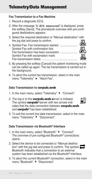
4. Symbol Fax: Fax transmission started. ....................... Symbol Fax with confirmation tick: Fax transmission has been successful. ...................... Symbol Fax with exclamation mark: Fax transmission failed. ..............................................
5. By pressing the softkey [Cancel] the patient monitoring mode can be called up again. The fax transmission is carried out in the background.
6. To abort the current fax transmission, select in the main menu "Telemetry" "Abort Fax".
Data Transmission to corpuls.web
1. In the main menu, select "Telemetry" "Connect".
2. The log-in to the corpuls.web server is initiated. The symbol corpuls3/server with two arrows indi-cates that the data connection between corpuls.web and corpuls3 has been established.
3. To exit the current live data transmission, select in the main menu "Telemetry" "Disconnect".
Data Transmission via Bluetooth® Interface
1. In the main menu, select "Bluetooth" "Connect". The overview of pre-configured Bluetooth® connections opens.
2. Select the device to be connected or "Manual destina-tion" with the jog dial and press to confirm. The symbol Bluetooth indicates that a connection to an external system has been established via the Bluetooth® interface.
3. To abort the current Bluetooth® connection, select in the main menu "Bluetooth" "Disconnect".
Telemetry/Data Management
18 ENG - Version 2.2 - P/N 04131.02
Alarm- and Event Management
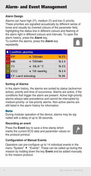
Alarm DesignAlarms can have high (!!!), medium (!!) and low (!) priority. These priorities are signalled acoustically by different series of tones and visually by inverted colours of the parameter field, highlighting the status line in different colours and flashing of the alarm light in different colours and intervals. To open the alarm history, press the Alarm key. To confirm the alarms, press the Alarm key repeatedly.
Sorting of AlarmsIn the alarm history, the alarms are sorted by status (active/non active), priority and time of occurrence. Alarms are active, if the conditions that trigger the alarm are present. Active high-priority alarms always take precedence and cannot be interrupted by medium-priority- or low-priority alarms. Non-active alarms are still listed in the alarm history for information.
NoteDuring modular operation of the device, alarms may be sig-nalled with a delay of up to 30 seconds.
Recording an eventPress the Event key to save a time stamp which marks the current ECG data and parameter values on the protocol printout.
Configuration of Manual EventsOperators can pre-configure up to 14 individual events in the menu "System" "Events". These can be called up during the mission by holding down the key Event and be added manually to the mission protocol.
19ENG - Version 2.2 - P/N 04131.02
Maintenance
Daily Check
1. Check the accessories/consumables for completeness.2. Perform a visual check of the device and the mechanical
connections.3. Switch on the compact device and check if the internal self-
test results in any error messages.4. Select manual defibrillation mode. Select an energy of 200 J
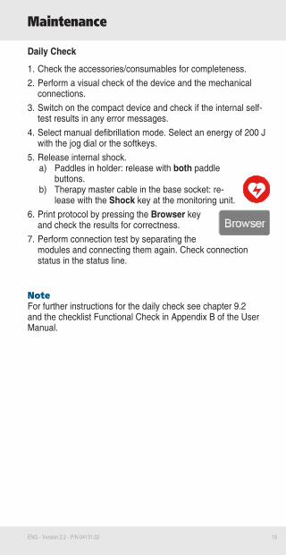
with the jog dial or the softkeys. 5. Release internal shock.
a) Paddles in holder: release with both paddle buttons.
b) Therapy master cable in the base socket: re-lease with the Shock key at the monitoring unit.
6. Print protocol by pressing the Browser key and check the results for correctness.
7. Perform connection test by separating the modules and connecting them again. Check connection status in the status line.
NoteFor further instructions for the daily check see chapter 9.2 and the checklist Functional Check in Appendix B of the User Manual.

20 ENG - Version 2.2 - P/N 04131.02
For further information please contact:
GS Elektromedizinische Geräte G. Stemple GmbH · Hauswiesenstraße 26 · 86916 Kaufering · Germany +49 8191 65722-0 · [email protected] · www.corpuls.com
Your business card