Embed Size (px)
Citation preview
1
TESLA Test Facility
MAMI, 27.01.05
Short Wavelength Free Electron Lasers at DESY
Dirk NölleDESY, MPY9-2579
TESLA Test Facility
Überblick:
• Warum das Ganze ?• Was ist ein Free-Electron-Laser?• Supraleitenden Beschleunigertechnologie @ DESY• TTF/VUV-FEL • Das Europäische X-FEL Projekt• Recent Results
TESLA Test Facility
Überblick:
• Warum das Ganze ?• Was ist ein Free-Electron-Laser?• Supraleitenden Beschleunigertechnologie @ DESY• TTF/VUV-FEL • Das Europäische X-FEL Projekt• Recent Results
TESLA Test Facility
Warum das Ganze?
• Strahlung ist ein wichtiges Werkzeug zur Beobachtung der Natur.
• Immer kleinere Strukturen benötigen immer kürzere Wellenlängen.
• Hohe Intensitäten erlauben die Beobachtung „extremer“ Vorgänge.
• Kohärenz: Holographische Bilder, räumliche Auflösung
• Kurze Pulse: Stroboskopische Beobachtung schneller Abläufe
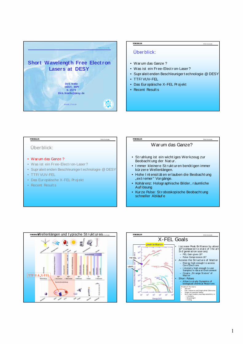
TESLA Test Facility Wellenlängen und typische Strukturen
TTF II & X-FEL
TESLA Test Facility
X-FEL Goals• Increase Peak Brilliance by about
109 (compared to state of the art 3rd generation sources)– FEL Gain gives 106
– Pulse Compression 103
• Access the Structure of Matter– Energy high enough to access
Core Electrons– Intensity high enough to use
Samples in natural Environment– Create „Strange States“ of
Matter• Short Pulses
– Allow to study Dynamics of biological/chemical Reactions
TTF FEL
LEUTL
peak brilliance
Dream of the Users:• 100 keV• Full transverse and longitudinal Coherence• Single Attosecond Spikes• With high Stability and Reproducibility in
• Intensity• Wavelength• Timing
2
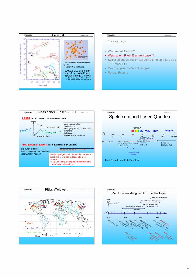
TESLA Test Facility Intensität
SASE FELs sind mehr als 109 x „so hell“ wie Speicherringe (im Peak)
– 103 durch kürzere Pulse (< 100 fs)– 106 die kohärente Wechselwirkung
Vielphotonenprozesse in Clustern@ TTF:T. Möller et al. in Nature
TESLA Test Facility
Überblick:
• Warum das Ganze ?• Was ist ein Free-Electron-Laser?• Supraleitenden Beschleunigertechnologie @ DESY• TTF/VUV-FEL • Das Europäische X-FEL Projekt• Recent Results
TESLA Test Facility „Klassischer“ Laser & FEL
hωhωpump
lasing line
ground state
inversed state
LASER: e- in festen Zuständen gebunden
Lasereigenschaften: •Wellenlänge•Übergangswahrscheinlichkeiten•Linenbreite•Pulslängehängen vom Material ab.
Free Electron Laser: Freie Elektronen im Vakuum,
die durch externe Beschleunigung zum Strahlen „gezwungen“ werden. Strahlungseigenschaften werden nur noch
durch die e- und die externen Kräfte bestimmt⇒ Es gibt keine prinzipielle Beschränkung
des Spektralbereichs.
TESLA Test Facility
Spektrum und Laser Quellen
]
Laser-Quellenheute
λ[nm] 1 0.1 E
[eV1000 100 10
1 10 100 1000 10000
sichtbares Licht800 - 400 nm
IR UV VUV XUV Röntgen100000 10000
0.01 0.1 ELETTRA, Trieste
iFEL 3, Japan
OK 4, DukeSuper ACO, Orsay
TTF I, HH
SCA, Stanford,CLIO, OrsayFelix, Utrecht
ENEA, FrascatiX-FEL, HHLCLS, Stanford
TTF II, HH
Eine Auswahl von FEL Facilities!
TESLA Test Facility FELs Weltweit
infrared
visible - UV
VUV – soft XRay
TESLA Test Facility
Zeitl. Entwicklung der FEL Technologie
1990 2000198019701971 first proposal
1976 first experimental proof
λ
μ
= 10.6 m
1977 first lasing
λμ
= 3.4 m
1983 first storage ring FEL
λ = 650 nm
1989 lasing in the UV
λ = 240 nm
1985 first FEL user facility
λ > 80 mμ
2000 SASE FEL
λ = 80 nm
1999 lasing in IR P > 1kW
lasing in UV avgλ = 200 nm
1957ubitron“FEL avant la lettre”
Star Wars
FIR FEL User Facilities2 - 500 mμ
FEL lightsource development
X-ray FEL development
Fundamental research
1980 first ideas about
an X-ray FEL
(SASE FEL)
1993 experimental
developments
towards X-ray
FELs
1996 first working
SASE FEL
2001 first user experiment at
= 100 nm
λ
3
TESLA Test Facility
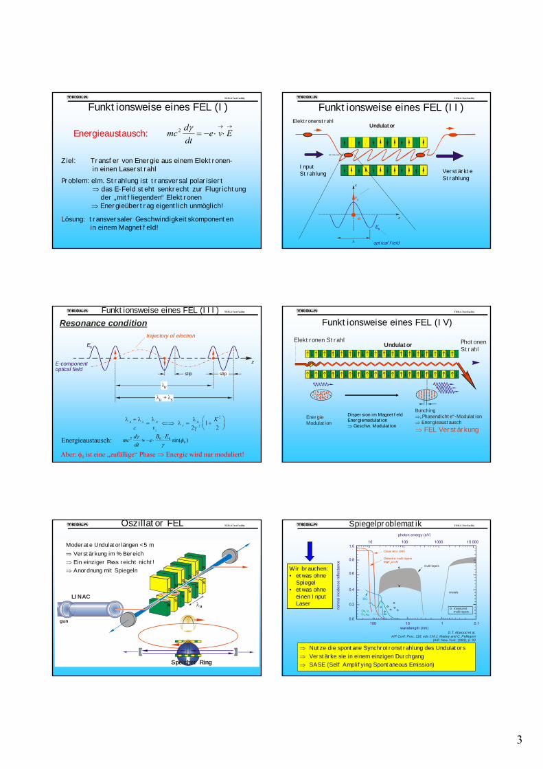
Funktionsweise eines FEL (I)
Ziel: Transfer von Energie aus einem Elektronen-in einen Laserstrahl
Problem: elm. Strahlung ist transversal polarisiert⇒ das E-Feld steht senkrecht zur Flugrichtung
der „mitfliegenden“ Elektronen⇒ Energieübertrag eigentlich unmöglich!
Lösung: transversaler Geschwindigkeitskomponenten in einem Magnetfeld!
→→
⋅⋅−= Evedtdmc γ2Energieaustausch:
TESLA Test Facility
Funktionsweise eines FEL (II)Undulator
Elektronenstrahl
VerstärkteStrahlung
InputStrahlung
optical field
z
x
vx
-e
Es
λ
TESLA Test Facility
Es
λu
λ λu s +
Resonance condition
E-componentoptical field
trajectory of electron
z
slip slip
λ λ λ λ λγ
u s u
zs
u
c vK+ = ⇐⇒ = +
⎛⎝⎜
⎞⎠⎟2
122
2
)sin( 0002 φ
γγ EBe
dtdmc ⋅
⋅−≈Energieaustausch:
Funktionsweise eines FEL (III)
Aber: φ0 ist eine „zufällige“ Phase ⇒ Energie wird nur moduliert!
TESLA Test Facility
PhotonenStrahl
Undulator
EnergieModulation
Elektronen Strahl
Bunching⇒„Phasendichte“-Modulation⇒ Energieaustausch⇒ FEL Verstärkung
Dispersion im MagnetfeldEnergiemodulation⇒ Geschw. Modulation
Funktionsweise eines FEL (IV)
TESLA Test Facility Oszillator FEL
gun
LINAC
SN
SN
SN uλ
NS
NS
NS
N
Speicher Ring
Moderate Undulatorlängen < 5 m⇒ Verstärkung im % Bereich⇒ Ein einziger Pass reicht nicht!⇒ Anordnung mit Spiegeln
TESLA Test Facility Spiegelproblematik
⇒ Nutze die spontane Synchrotronstrahlung des Undulators⇒ Verstärke sie in einem einzigen Durchgang⇒ SASE (Self Amplifying Spontaneous Emission)
D.T. Attwood et al,AIP Conf. Proc. 118, eds J.M.J. Madey and C. Pellegrini
(AIP, New York, 1983), p. 93
Clean Al in UHV
Dielectr ic multi-layersMgF on Al2
SiC
Os, Ir,Pt, Au
multi- layers
cristals
measuredmulti-layers
norm
al in
cide
nce
refle
ctan
ce
100 10 1 0.1
10 100 1000 10 000
wavelength (nm)
photon energy (eV)
1.0
0.8
0.6
0.4
0.2
0.0
Wir brauchen:• etwas ohne
Spiegel• etwas ohne
einen Input Laser
4
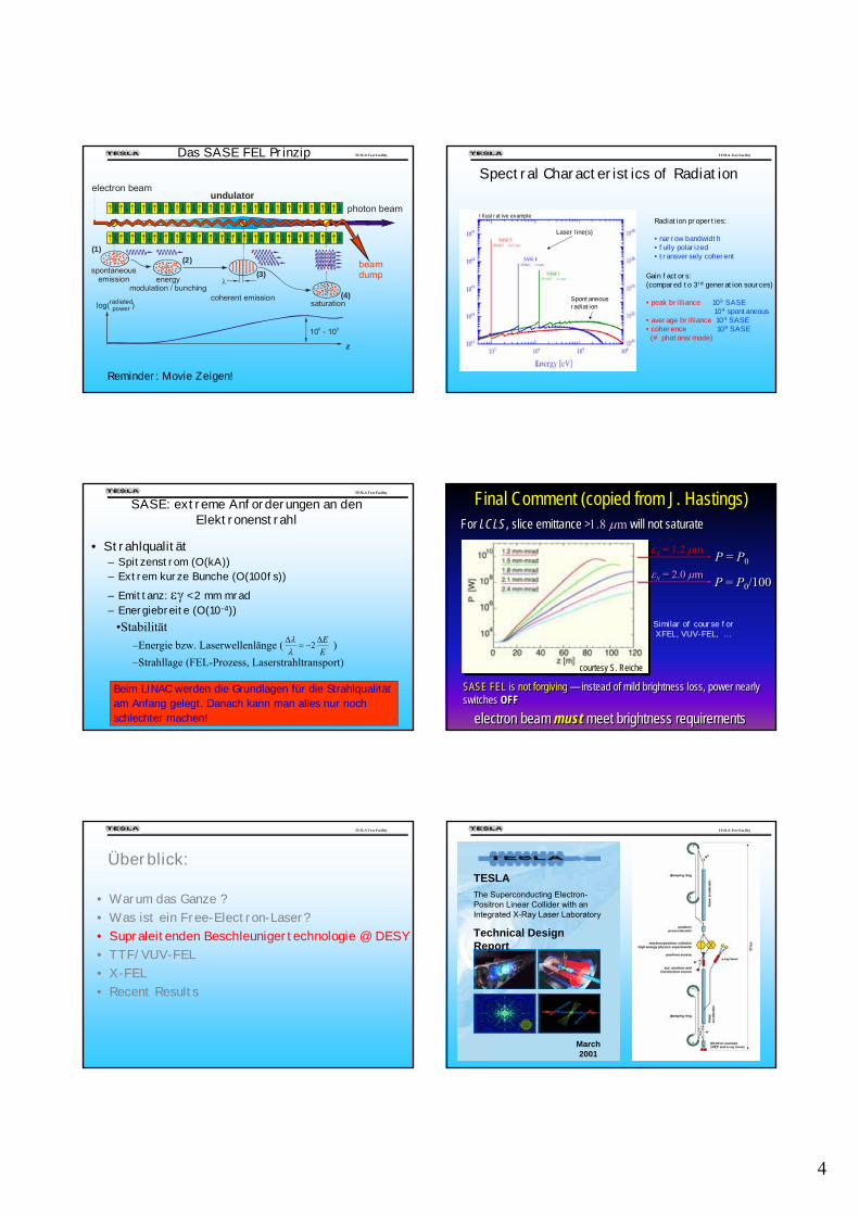
TESLA Test Facility Das SASE FEL Prinzip
undulator
energymodulation / bunching
spontaneousemission
beamdump
photon beam
electron beam
λ
coherent emissionsaturationradiated
powerlog( )
z
10 - 106 9
(1)(2)
(3)
(4)
Reminder: Movie Zeigen!
TESLA Test Facility
Laser line(s)
Spontaneous radiation
Spectral Characteristics of Radiation
Radiation properties:
• narrow bandwidth• fully polarized• transversely coherent
Gain factors:(compared to 3rd generation sources)
• peak brilliance 109 SASE104 spontaneous
• average brilliance 104 SASE• coherence 109 SASE(# photons/mode)
Illustrative example
TESLA Test Facility
• Strahlqualität– Spitzenstrom (O(kA))– Extrem kurze Bunche (O(100fs))– Emittanz: εγ < 2 mm mrad– Energiebreite (O(10-4))
SASE: extreme Anforderungen an den Elektronenstrahl
•Stabilität–Energie bzw. Laserwellenlänge ( )–Strahllage (FEL-Prozess, Laserstrahltransport)
EEΔ
−=Δ 2λλ
Beim LINAC werden die Grundlagen für die Strahlqualität am Anfang gelegt. Danach kann man alles nur noch schlechter machen!
For LCLS, slice emittance >1.8 μm will not saturate For LCLS, slice emittance >1.8 μm will not saturate
SASE FEL is not forgiving — instead of mild brightness loss, power nearly switches OFFSASE FEL is not forgiving — instead of mild brightness loss, power nearly switches OFF
Final Comment (copied from J. Hastings)Final Comment (copied from J. Hastings)
courtesy S. Reiche
P = P0P = P0εN = 1.2 μmεN = 1.2 μm
P = P0/100P = P0/100εN = 2.0 μmεN = 2.0 μm
electron beam must meet brightness requirementselectron beam must meet brightness requirements
Similar of course forXFEL, VUV-FEL, …
TESLA Test Facility
Überblick:
• Warum das Ganze ?• Was ist ein Free-Electron-Laser?• Supraleitenden Beschleunigertechnologie @ DESY• TTF/VUV-FEL • X-FEL• Recent Results
TESLA Test Facility
TESLAThe Superconducting Electron-Positron Linear Collider with an Integrated X-Ray Laser Laboratory
Technical Design Report
March 2001
5
TESLA Test Facility
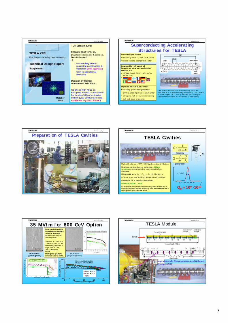
TESLA XFELFirst Stage of the X-Ray Laser Laboratory
Technical Design ReportSupplement
October 2002
TDR update 2002:
Separate linac for XFEL(maintain common site & same s.c. linac technology)
• De-coupling from LC regarding construction & operation (and: approval)
• Gain in operational flexibility
Decision by German Government Feb. 2003:
Go ahead with XFEL as European Project, commitment for funding 50% of estimated 684 M€ (year 2000 price basis, escalation y2012: 908M€ )
TESLA Test Facility
Superconducting AcceleratingStructures for TESLA
HOM coupler
power coupler
HOM coupler
rf pick up
115.4 mm
1036 mm
1256 mmGoal during past decade
• Increase gradients from 5 to 25 MV/m
• Reduce costs by a comparable factor
Common effort of almost all laboratories using s.c. accelerating cavities, e.g.
• (CERN), Cornell, DESY, INFN, (KEK), Saclay, TJNL
• 40 partners from 11 countries
Improved material quality check
New cavity preparation procedures
• 1400 ºC annealing with a titanium getter
• ultra-pure, high pressure water rinsing
• high peak power processing
One standard 9-cell TESLA accelerating structure operated as a π-mode standing-wave cavity. One 230 kW rf input coupler, an rf pick up antenna and two Higher Order Mode antennas are assembled to each cavity.
TESLA Test Facility
Preparation of TESLA Cavities TESLA Test Facility
TESLA Cavities
Q0 ≈ 109 -1010
RsLC
so R
GffQ =Δ
=
LCfo π2
1=
frequency
quality factor
ff0 = 1,300,000,000 Hz
Δ f ≈ 1 Hz
Made with solid, pure (RRR >300, high thermal cond.) Niobium
Nb sheets are deep-drawn to make cups (≈100 µm tolerances), which are electron beam welded to form structures.
Fill time 420 µs, i.e. Qext = Qbeam ≈ 3 x 10⁶, Δf ≈ 400 Hz
RF pulse length (400 µs filling + 920 µs flat top) = 1320 µs.
Operated at 2 K in superfluid Helium bath.
RF losses approx. 1 W/m.
RF amplitude and phase adjusted during filling and flat top to compensate beam loading. In steady state essentially 100% rfinput power goes into the beam.
TESLA Test Facility
35 MV/m for 800 GeV Option
Unl
oade
d Q
ualit
y Fa
ctor
Q0
Accelerating Gradient ( MV/m )
Excitation Curves for Cavities from the 3rd Production Series
TESLA goal
TESLA goal
First electro-polished single cell cavities
BCP Surface (1µm roughness)
EP Surface (0.1µm roughness)
BCP Surface (1µm roughness)
0.5 mm 0.5 mm
Electro-polishing (EP)instead of the standard chemical polishing (BCP) eliminates grain boundary steps.
Gradients of 40 MV/m at Q values above 1010 are now reliably achieved in single cells at KEK, DESY/CERN and TJNAF.The highest gradient achieved was 42 MV/m.
A C 70 AC 72
A C 73 AC 78
A C 76
Electro-polished Cavities Measured in Vertical Test
Accelerating Gradient (MV/m)
Unl
oade
d Q
ualit
y Fa
ctor
109
1010
1011
0 10 20 30 40
TESLA Test Facility
TESLA Module
Strahl
supraleitende Resonatoren aus Niobium(Temp = 2 K)
6
TESLA Test Facility
Überblick:
• Warum das Ganze ?• Was ist ein Free-Electron-Laser?• Supraleitenden Beschleunigertechnologie @ DESY• TTF/VUV-FEL • X-FEL• Recent Results
TESLA Test Facility
dump
Lase
r superconducting cavities
bunch compressor
rf-gun FELbeam
undulatorcollimator
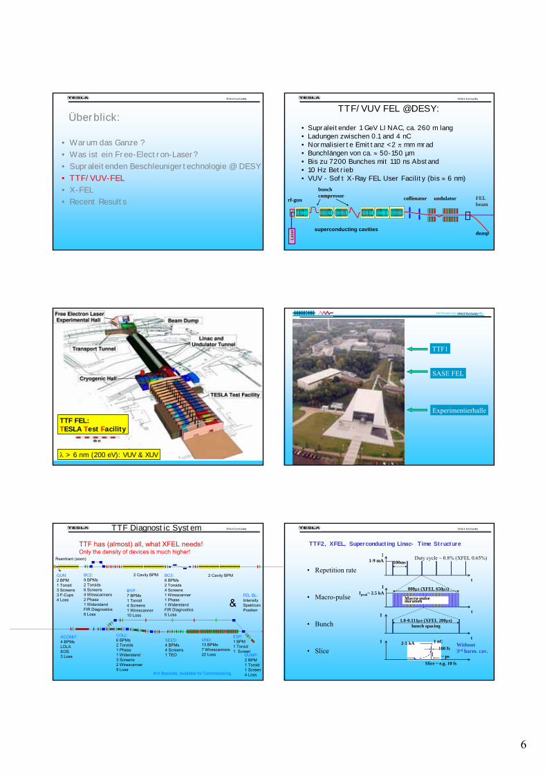
TTF/VUV FEL @DESY:
• Supraleitender 1 GeV LINAC, ca. 260 m lang• Ladungen zwischen 0.1 and 4 nC• Normalisierte Emittanz < 2 π mm mrad• Bunchlängen von ca. ≈ 50-150 µm• Bis zu 7200 Bunches mit 110 ns Abstand• 10 Hz Betrieb• VUV - Soft X-Ray FEL User Facility (bis ≈ 6 nm)
TESLA Test Facility
TTF II
TTF FEL: TESLA Test Facility
λ > 6 nm (200 eV): VUV & XUV
TESLA Test Facility
TTF1
SASE FEL
Experimentierhalle
Free-Electron Laser at the TESLA Test Facility
TESLA Test Facility TTF Diagnostic System
Injektor II
GUN:2 BPM1 Toroid3 Screens3 F-Cups4 Loss
BC2:9 BPMs2 Toroids6 Screens4 Wirescanners2 Phase1 WiderstandFIR Diagnostics6 Loss
BC3:6 BPMs2 Toroids4 Screens1 Wirescanner1 Phase1 WiderstandFIR Diagnostics6 Loss
ACC6&7:4 BPMsLOLAEOS3 Loss
BYP:7 BPMs1 Toroid4 Screens1 Wirescanner10 Loss
COLL:6 BPMs2 Toroids1 Phase1 Widerstand3 Screens2 Wirescanner9 Loss
SEED:4 BPMs4 Screens1 TEO
UND:13 BPMs7 Wirescanners22 Loss DUMP:
2 BPM1 Toroid1 Screen4 Loss
EXP:1 BPM1 Toroid1 Screen
2 Cavity BPM 2 Cavity BPM
Reentrant (soon)
FEL BL:IntensitySpektrumPosition
&
TTF has (almost) all, what XFEL needs!Only the density of devices is much higher!
# in Brackets: Available for Commissioning
TESLA Test Facility
• Repetition rate
• Macro-pulse
• Bunch
• Slice
t
I100ms
Duty cycle ~ 0.8% (XFEL 0.65%)1-9 mA
t
I 800μs (XFEL 650μs)Ipeak~ 2.5 kA
Macro-pulse duration
It
I1.0-0.111μs (XFEL 200μs)
bunch spacing
1 nC100 fs
2-5 kA
~ psSlice ~ e.g. 10 fs
Without3rd harm. cav.
TTF2, XFEL, Superconducting Linac- Time Structure
7
TESLA Test Facility
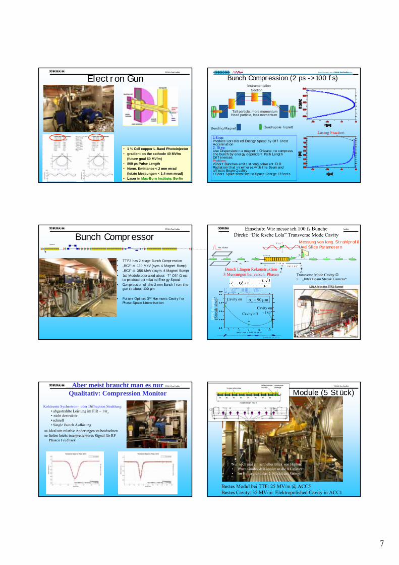
Electron Gun
• 1 ½ Cell copper L-Band Photoinjector• gradient on the cathode 40 MV/m
(future goal 60 MV/m)• 800 µs Pulse Length• Norm. Emittance < 2 mm mrad
(letzte Messungen < 1.4 mm mrad)• Laser in Max-Born Institute, Berlin
TESLA Test Facility
Bunch Compression (2 ps -> 100 fs)
1 Step: Produce Correlated Energy Spead by Off CrestAcceleration2. Step:Use Dispersion in a magnetic Chicane, to compressthe bunch by energy dependent Path LengthDifferences.Problem:•Short Bunches emitt strong coherent FIR Radiation that interferes with the Beam and affects Beam Quality• Short Spike sensitive to Space Charge Effects
Lasing Fraction
Free-Electron Laser at the TESLA Test Facility
InstrumentationSection
Bending Magnet Quadrupole Triplett
Tail particle, more momentumHead particle, less momentum
TESLA Test Facility
Bunch Compressor
• TTF2 has 2 stage Bunch Compression• „BC2“ at 120 MeV (sym. 4 Magnet Bump)• „BC3“ at 350 MeV (asym. 4 Magnet Bump)• 1st Module operated about -7° Off Crest
to produce correlated Energy Spead• Compression of the 2 mm Bunch from the
gun to about 100 µm
• Future Option: 3rd Harmonic Cavity forPhase Space Linearisation
Injektor II
TESLA Test Facility
Transverse Mode Cavity ☺• „Intra Beam Streak Camera“
ΔΔ ψψ ≈≈ 66 00 °°
ee −−
VV (( tt ))
ee−
σσ zz
yy
22 .. 44 44 mm
ββ cc ββ pp
⟩
2 π
TM 11
ee −−ee −− ee −− ee −−σσ
Hor. Kicker
−z
ee −ee −ee −
Messung von long. StrahlprofilUnd Slice Parametern
A = 1.6696E-02 STD DEV = 1.3536E-03B = 28.23 STD DEV = 3.084C = 1328. STD DEV = 8.235RMS FIT ERROR = 23.63
-80 -40 0 40 80
SBST LI29 1 PDES (S-29-1)
1.7
1.6
1.5
1.4
1.3
X103
****
***
**
**
*
****
********
0 40 80
SBST LI29 1 PDES (S-29-1)
1.7
1.6
1.5
1.4
1.3
X103
E
0 40 80
1.7
1.6
1.5
1.4
1.3
X103
0 40 80
1.7
1.6
1.5
1.4
1.3
X103
0 40 80
1.7
1.6
1.5
1.4
1.3
X103
0 40 80
1.7
1.6
1.5
1.4
1.3
X103
E
1-APR-03 20:21:16
Cavity on
Cavity offCavity on
- 180°
Bunch Längen Rekonstruktion3 Messungen bei versch. Phasen
σz = 90 μm
(Stre
ak si
ze)2
SPPS
Exa
mpl
e
Einschub: Wie messe ich 100 fs BuncheDirekt: “Die fesche Lola” Transverse Mode Cavity
TESLA Test Facility Aber meist braucht man es nurQualitativ: Compression Monitor
Kohärente Sychrotron- oder Diffraction Strahlung: • abgestrahlte Leistung im FIR ~ 1/σz• nicht destruktiv• schnell• Single Bunch Auflösung
⇒ ideal um relative Änderungen zu beobachten⇒ liefert leicht interpretierbares Signal für RF
Phasen Feedback
TESLA Test Facility
Module (5 Stück)
Nur noch mal ein schneller Blick von Hinten: • Wave Guides & Koppler an die 8 Cavities• Im Hintergrund das 2. Modul des Strings
Bestes Modul bei TTF: 25 MV/m @ ACC5Bestes Cavity: 35 MV/m: Elektropolished Cavity in ACC1
8
TESLA Test Facility
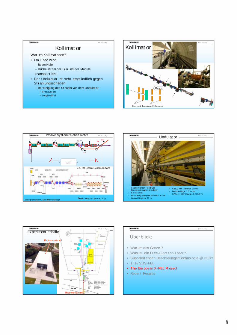
KollimatorWarum Kollimatoren?• Im Linac wird
– Beam Halo– Dunkelstrom der Gun und der Moduletransportiert
• Der Undulator ist sehr empfindlich gegen Strahlungsschäden – Bereinigung des Strahls vor dem Undulator
• Transversal• Longitudinal
TESLA Test Facility
Energy & Transverse Collimation
Beam
Kollimator
TESLA Test Facility Passive System reichen nicht!
Lase
r
T 8T 2 ,T 3 T 4 ,T 5 T 6 , T 7 T 9T 1 0
T 1 1
Lase
r
T 8T 2 ,T 3T 2 ,T 3 T 4 ,T 5T 4 ,T 5 T 6 , T 7 T 9T 1 0
T 1 1
T o r o idP r o te c t io n
S y s t e m
Reaktionszeiten ca. 3 µs
Ca. 60 Beam Lossmonitore
(plus permenente Dosisüberwachung)
TESLA Test Facility Undulator
• Segmentierter fixed GapPermanentmagnet Undulator
• 6 Sektionen • externe Quadrupole in FoDo Lattice• Gesamtlänge ca. 30 m
• Gap 12 mm (Kammer 10 mm)• Periodenlänge: 27,3 mm• K-Wert: 1,22 (Bpeak= 0.4859 T)
TESLA Test Facility
Experimentierhalle
Photonenstrahl
Photonenstrahl
TESLA Test Facility
Überblick:
• Warum das Ganze ?• Was ist ein Free-Electron-Laser?• Supraleitenden Beschleunigertechnologie @ DESY• TTF/VUV-FEL • The European X-FEL Project• Recent Results
9
TESLA Test Facility
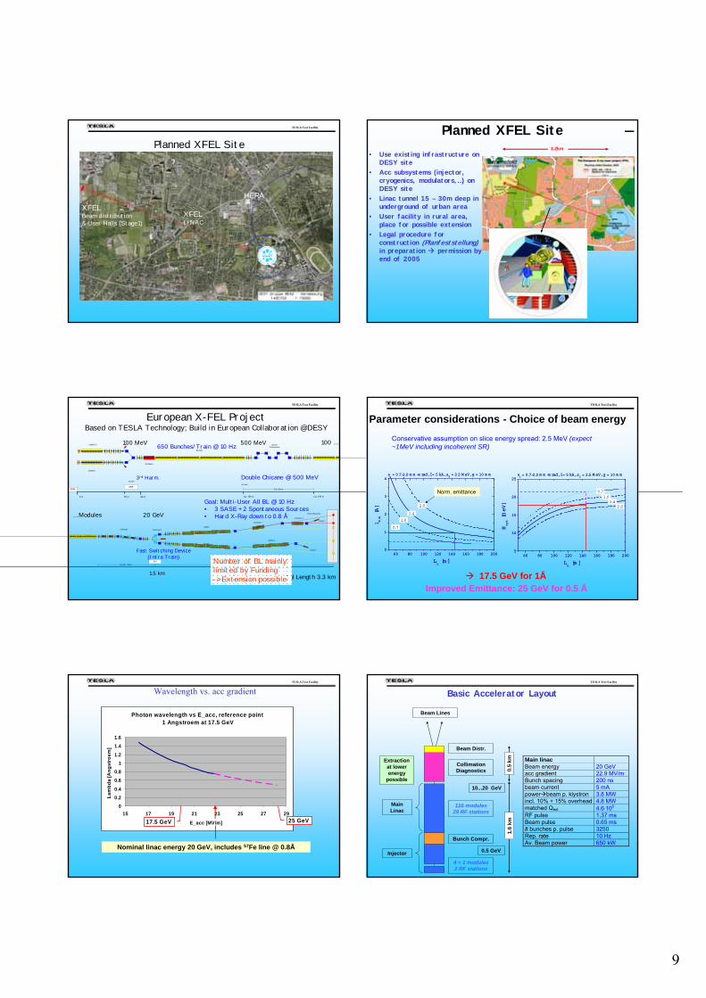
Planned XFEL Site
HERA
XFEL LINAC
XFELBeam distribution& User Halls (Stage1)
TESLA Test Facility Planned XFEL Site• Use existing infrastructure on
DESY site• Acc subsystems (injector,
cryogenics, modulators,…) on DESY site
• Linac tunnel 15 – 30m deep in underground of urban area
• User facility in rural area, place for possible extension
• Legal procedure for construction (Planfeststellung)in preparation permission by end of 2005
3.2km
TESLA Test Facility
European X-FEL ProjectBased on TESLA Technology; Build in European Collaboration @DESY
Injektor II
Injektor I
Booster
3rd Harm.
XSINXSE
50 m 80 m
500 MeV
BunchCompressor
Ca. 150 m
Ca. 120 m
Ca. 270 m0 m
100 MeV
Collimator Switchyard
Ca. 400 - 500 m
XS1 ca. 1150 m
SASE I
Dump I
Photon Beamline
SASE II
Dump II
SASE III
Undulator I
Undulator II
100 MeV 500 MeV
20 GeV
Total Length 3.3 km
Goal: Multi-User All BL @ 10 Hz• 3 SASE + 2 Spontaneous Sources• Hard X-Ray down to 0.8 Å
1.5 km
Fast Switching Device(Intra Train)
3rd Harm. Double Chicane @ 500 MeV
650 Bunches/Train @ 10 Hz
Number of BL mainly limited by Funding-> Extension possible
… Modules
100 …
TESLA Test Facility
60 80 100 120 140 160 180 2000
1
2
3
4
2.0
1.4
1.0
0.7
en = 0.7-2.0 m m -m rad, I = 5 kA, s
E = 2.5 M eV, g = 10 m m
lmin [A]
Lu [m ]
60 80 100 120 140 160 180 2005
10
15
20
25
2.0 1.4
1.0
en = 0.7-2.0 m m -m rad, I = 5 kA, s
E = 2.5 M eV, g = 10 m m
Eopt [GeV]
Lu [m ]
0.7
Parameter considerations - Choice of beam energyConservative assumption on slice energy spread: 2.5 MeV (expect ~1MeV including incoherent SR)
60 80 100 120 140 160 180 2000
1
2
3
4
2.0
1.4
1.0
0.7
en = 0.7-2.0 m m -m rad, I = 5 kA, s
E = 2.5 M eV, g = 10 m m
lmin [A]
Lu [m ]
60 80 100 120 140 160 180 2005
10
15
20
25
2.0 1.4
1.0
en = 0.7-2.0 m m -m rad, I = 5 kA, s
E = 2.5 M eV, g = 10 m m
Eopt [GeV]
Lu [m ]
0.7
17.5 GeV for 1Å
Norm. emittance
Improved Emittance: 25 GeV for 0.5 Å
TESLA Test Facility
Wavelength vs. acc gradient
Photon wavelength vs E_acc, reference point 1 Angstroem at 17.5 GeV
00.20.4
0.60.8
11.2
1.41.6
15 17 19 21 23 25 27 29
E_acc [MV/m]
Lam
bda
[Ang
stro
em]
25 GeV17.5 GeV
Nominal linac energy 20 GeV, includes 57Fe line @ 0.8Å
TESLA Test Facility
0.5 GeV
CollimationDiagnostics
116 modules29 RF stations
4 + 1 modules2 RF stations
Bunch Compr.
10...20 GeV
Beam Distr.
Injector
Main Linac
Beam Lines
1.6
km0.
5 kmExtraction
at lowerenergy
possible
Basic Accelerator Layout
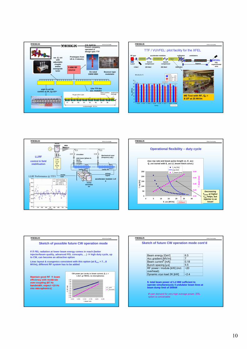
Main linac Beam energy 20 GeV acc gradient 22.9 MV/m Bunch spacing 200 ns beam current 5 mA power beam p. klystron 3.8 MW incl. 10% + 15% overhead 4.8 MW matched Qext 4.6⋅106 RF pulse 1.37 ms Beam pulse 0.65 ms # bunches p. pulse 3250 Rep. rate 10 Hz Av. Beam power 650 kW
10
TESLA Test Facility
5 MW RFsource
De-rated 10MW MBK
Bouncer-type modulator
var. Q_extwith
adjustable coupler and/or
waveguide tuner
eight 9-cell Nbcavities at 2K, Q0=1010
12m TTF-like acc. modules
3 kl. built by French company, operated @ design spec TTF
Prototypes from US & J industry
TESLA Test Facility
RF gun
FEL experimental
area
bypass
4 MeV 150 MeV 450 MeV 1000 MeV
undulatorscollimator
bunch compressorLaser
bunch compressor
accelerator modules
TTF / VUVFEL: pilot facility for the XFEL
1 - AC62 2 - AC61 3 - AC65 4 - AC66 5 - AC79 6 - AC77 7 - AC63 8 - AC600
5
10
15
20
25
30
35
BD
dark current src
Module 5
1 4 .0 9 .2 0 0 3
E ACC [M
V/m
]
Cavity
Cavity tests: Vertical (CW) Horizontal (10Hz) Module 5 (1Hz) Module 5 (5Hz)
M5 Test with RF, Q0 = 8⋅109 at 25 MV/m
TESLA Test Facility
Mechanical tuner (frequency adj.)
DA
C DA
C
ADCADC
LowLevelRF
System
vector sum
vector demodula
tor
pickup signal
MBK Klystron
vector modulat
or
cavity #1 cavity #8
coaxial coupler
circulator
stub tuner (phase & Qext)
accelerator module 1 of 4
LLRF control & field stabilisation
LLRF Performance @ TTF1
TESLA Test Facility
max rep rate and beam pulse length vs. E_accQ_ext varied with E_acc (I_beam=5mA const.)
0
50
100
150
200
250
0 5 10 15 20 25 30
E_acc [MV/m]
f_re
p [H
z]
0.00
0.20
0.40
0.60
0.80
f_rep [Hz]cryo-limitT_beam [ms]
20GeV
Operational flexibility – duty cycle
T_be
am[m
s]
Decreasing Tbeam at higher frep helps, but injector is an
issue!
TESLA Test Facility
CW power per cavity vs beam current, Q_L = 1.5e7, g=7MV/m, no microphonics
0.000.200.400.600.801.001.201.401.601.802.00
0.000 0.050 0.100 0.150 0.200 0.250
I_beam / mA
P_R
F / k
W
P_g/kWP_beam/kW
Maintain good RF beam efficiency with moderate over-coupling (87 Hz bandwidth, expect <10 Hz rms microphonics)
Sketch of possible future CW operation mode
If Å FEL radiation at lower beam energy comes in reach (better injector/beam quality, advanced FEL concepts, …) high duty cycle, up to CW, can become an attractive option
Linac layout & cryogenics consistent with this option (at Eacc = 7…8 MV/m), different RF system has to be added
TESLA Test Facility
Beam energy [GeV] 6.5 Acc gradient [MV/m] 7 Beam current$ [mA] 0.18 Bunch spacing [μs] 5.5 RF power / module [kW] (incl. overhead)
~20
Dynamic cryo load 2K [kW] ~2.4 $: total beam power of 1.2 MW sufficient to operate simultaneously 4 undulator beam lines at beam dump limit of 300kW
Sketch of future CW operation mode cont’d
If user demand for very high average power, ERL option is conceivable
11
TESLA Test Facility
Injector I
Injector II
ca. 270 mca. 150 m80 m0 m
XSIN
3rd Harmonic Booster Bunch Compressor
Main Linac >100 Modules
XSE
50 m
100 MeV 500 MeV
XTL
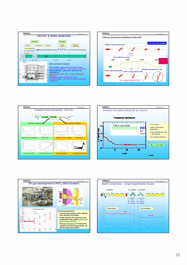
Injector & bunch compressor
Start-to-end beam simulations:
ASTRA (DESY) - space charge dominated e-beamsTraFiC4/CSRtrack(DESY) - self-consistent CSR effectsMAFIA (TUD/CST) - general e.m. field solver forwakefields etc.elegant (Argonne Natl. Lab.) - e-beam tracking withwakefieldsGENESIS1.3 (DESY) - 3D SASE FEL codeFAST (DESY/JINR) - fast SASE FEL code for parameteroptimization
TESLA Test Facility
Coherent Synchrotron Radiation (CSR) in BC
Without CSR self-interaction
With CSR self-interaction
DM3 DM4DM2DM1
Head : energy gain by CSR
Tail : energy loss due to CSR
Head with lower energy
x
z
emittance growth due to CSR
EdE
x
x
η
η
β +=
≠
xx
BCin0
Courtesy of M. Dohlus
TESLA Test Facility
Example of start-to-end analysis: TTF1 FEL
Emittance (x-solid, y-dashed) Emittance (x-solid, y-dashed)Peak current Peak current
Slice energy spread Slice energy spreadLongitudinal phase space Longitudinal phase space
after bunch compressor at entrance of undulator
TESLA Test Facility
Emittance from photocathode RF gun injector
- 1nC charge
- uniform transverse distribution
- longitudinal flat-top with2 ps rise time
- incl. thermal emittance
n = 0.9 μmε
TESLA Test Facility
On-going programme:• increase the gradient on the cathode
from 40 MV/m to 60 MV/m• further improve the transverse and
longitudinal laser profile (collab. Max-Born Institute, Berlin)
• PITZ gun now part of TTF-II/VUVFEL injector (commissioning started, not yet flat long. laser profile)
RF gun development at PITZ, DESY-Zeuthen
1.7
TESLA Test Facility
ACC1 ACC2 ACC3 ACC4 ACC5RFGUNBC1
3rdhrm ACC6 ACC7 ACC8BC2
E =510 MeVσδ ~ 1.89%R56 = 87 mmθ = 3.95 deg
E = 510 MeVσδ ~ 1.88%R56 = 4.8 mmθ = 0.93 deg
σz=1.8mm σz=21μmσz=113μm
Bunch compressor – single stage/double chicane
1.4 μm
5 kA
Peak current Hor. emittance
12
TESLA Test Facility
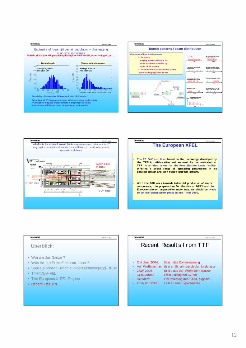
Estimate of beam jitter at undulator – challenging stabilization issues
Average σz=19μm rms jitter 19%
Average P=50GW rms jitter 41%
Bunch length Photon saturation power
Model calculation: RF phase/amplitude jitter 0.05º/0.02%, laser timing 0.1ps,…
Possibility of intra-pulse RF feedback with SRF helpful
Advantage of 2nd stage compressor at higher energy under study reduction of space charge effects in diagnostics section
downstream, additional room for parameter optimization
TESLA Test Facility
Generation of bunch train patterns:– At the source
� varying transient effects in the entire accelerator (handled e.g. by the LLRF system)
– At the beam delivery / distribution system � more challenging kicker devices
Bunch patterns / beam distribution
5MHz bunch train
beam line #1
beam line #2
beam line #3
programmable fast kickers
pilot train(stab. Feedback)
TESLA Test Facility
included in the detailed layout: Kicker/septum concept, extension for 2nd
stage and accessability of tunnels for installation etc., while others are in operation with beam
From linac
SASE1 & 2 of 1st stage
2nd stage
TESLA Test Facility
• The 20 GeV s.c. linac based on the technology developed by the TESLA collaboration and successfully demonstrated at TTF is an ideal driver for the Free Electron Laser facility, offering a broad range of operating parameters in its baseline design and with future upgrade options.
• With the R&D work towards industrial production of major components, the preparations for the site at DESY and the European project organisation under way, we should be ready to go into construction phase in mid – end 2006.
The European XFEL
TESLA Test Facility
Überblick:
• Warum das Ganze ?• Was ist ein Free-Electron-Laser?• Supraleitenden Beschleunigertechnologie @ DESY• TTF/VUV-FEL • The European X-FEL Project• Recent Results
TESLA Test Facility
Recent Results from TTF
• Oktober 2004: Start des Commissioning• Vor Weihnachten: Erster Strahl durch den Undulator• 2KW 2005: Start aus der Weihnachtspause• 14.01.2005: First Lasing bei 32 nm• Seitdem: Optimierung des SASE Signals• Frühjahr 2005: Erste User Experimente
13
TESLA Test Facility
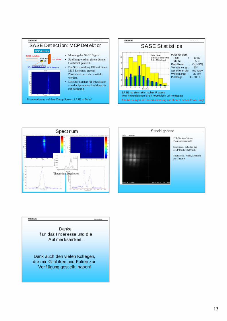
SASE Detection: MCP Detektor
• Messung des SASE Signal• Strahlung wird an einem dünnen
Golddraht gestreut.• Die Streustrahlung fällt auf einen
MCP Detektor, erzeugt Photoelektronen die verstärkt werden.
• Detektor nutzbar für Intensitäten von der Spontanen Strahlung bis zur Sättigung
MCP detector
MCP detector
Gold wire250 µm
SiC mirror
SASE radiation
U
Fragmentierung auf dem Dump Screen: SASE ist Nahe!
TESLA Test Facility
Pulsenergien:Peak : 10 µJMittel : 5 µJ
PeakPower : O(1 GW)Verstärkung : 105
Strahlenergie: 450 MeVWellenlänge : 32 nmPulslänge :10-20 fs
Gelb : PeakBlau : Aktueller PulsGrün: Mittelwert
SASE ist ein statistischer Prozess40% Fluktuationen sind theoretisch vorhergesagtAlle Messungen in Übereinstimmung zur theoretischen Erwartung!
SASE Statistics
TESLA Test Facility Spectrum
Theoretical Prediction
TESLA Test Facility StrahlgrösseFEL Spot auf einem Floureszenskristall
Strukturen: Schatten des MCP Meshes (250 µm)
Spotsize ca. 3 mm, konform zur Theorie
TESLA Test Facility
Dank auch den vielen Kollegen, die mir Grafiken und Folien zur
Verfügung gestellt haben!
Danke,für das Interesse und die
Aufmerksamkeit.