Embed Size (px)
Citation preview

SHOT TIMER AND TRIGGER CONTROL KIT
PART NUMBER: 43966K
Installation and Parts Manual – 38017N
REV 0 - 6/26/18

Page 2 of 10

Page 3 of 10
FEATURES
This kit is designed to add the following functions to a Crafco Sealant Melter that has an
electric hose and wand:
Trigger Switch
o Wand or Foot Switch (Optional, Foot Switch not included in this kit)
Mode Switch
o Manual – material pump will run for as long as the selected trigger is
actuated
o Marker – uses the internal “Marker Shot Timer”. This timer can be set from
0 to 5 seconds. The material pump will run for the set amount of time,
regardless of duration of trigger actuation
Marker Shot Timer
o Sets the run duration for the material pump when the mode switch is in the
“Marker” position.
NOTE: this kit is not compatible with EZ Series II machines having a standard (non-
electric) hose.
CONTACT US
Crafco, Inc.
6165 W. Detroit Street, Chandler, AZ 85266
Phone: +1 602 276 0406 Fax: +1 480 961 0513

Page 4 of 10
INSTALLATION
This kit wires into the electric hose junction box located near the base of the hose where it exits the material tank. Step by Step Instructions:
1. Mount the shot timer box to the material tank near the hose junction box (ensuring the wire harness on the shot timer will reach into the hose junction box)
a. Be sure to use the white plastic stand-offs to keep the shot timer box off the hot surface of the material tank
2. Open the hose junction box using a flat screwdriver 3. Unscrew the clamp nut on the cable grip on the bottom
of the hose junction box 4. Pull back the black harness loom covering the existing
wire assembly through the cable grip such that there is no longer any harness loom in the cable grip… leave this loom end loose for now (do not cut yet)
5. Pull back about 6” of the harness loom from the terminal end of the wires on the shot timer box…leave this loom end loose for now (do not cut yet)
6. Feed the shot timer wires, one by one, through the clamp nut and through the cable grip and into the hose junction box
7. Unscrew the large Philips head screw to the right of the terminal strips inside the hose junction box and install the ring terminal on the black ground wire and re-tighten
8. Loosen the screws on the terminal strip holding the 2 RED wires coming from the electric hose – pull the fork terminals for these 2 wires free from the screws
9. Connect the RED and GRN wires from the shot timer to these screw posts – matching colors with the wires on the other side of the terminal strip
10. Cut off the fork terminals on the 2 RED wires from the hose and crimp on the female quick disconnect terminals included with the kit
11. Plug in these 2 RED wires into the 2 RED/BLK wires from the shot timer. Which RED wire plugs into which RED/BLK wire does not matter, but both must be connected.
STEP 1
STEP 7
STEP 9
STEP 11

Page 5 of 10
INSTALLATION (Cont.)
12. The 2 remaining ORN wires from the shot timer are for the optional Foot Switch. If a Foot Switch is not being installed at this time, tuck these wires into the hose junction box
13. Re-install the clamp nut on the cable grip on the bottom of the hose junction box and tighten
14. Trim the loose harness loom pieces from steps 4 and 5 such that they end about 1” below the cable grip
15. Using electrical tape, starting at the bottom of the cable grip, tape the cable bundle firmly together working down and over the cut ends of the harness loom, securing the loom with tape
STEP 15

Page 6 of 10
OPERATION
CRACK SEALING:
The Mode Switch should be in the “Crack Seal” position.
The Trigger Switch selects which trigger will control the operation of the material pump.
All other machine functions are accessed from the main machine control box as before the shot timer was installed. Refer to machine manual for all other functions and precautions
NOTE: If a Foot Switch is not installed on the machine, then the Trigger Switch should NEVER be set to the Foot Switch position.
MARKER APPLICATION:
The Mode Switch should be in the “Marker” position.
The Trigger Switch selects which trigger will START the material pump, but in this mode, the trigger does NOT control the DURATION that the material pump runs. The pump will run for the amount of time set with the “Marker Shot Timer” knob.
The Marker Shot Timer sets how long the material pump will run each time the trigger is actuated. The time can be set from 0 to 5 seconds.
To control the amount of material dispensed, use the following 2 controls together: o Marker Shot Timer setting (sets how long the pump runs) o Material flow control valve (how fast material flows while pump is running) –
refer to machine manual for further details on the material flow control valve
IMPORTANT NOTE: In Marker mode, the trigger only initiates material pump operation. Releasing the trigger will not stop material flow! Material will continue to flow until the set time has expired, only then will the pump stop. Holding the trigger will not cause the material to continue to flow – again, the material pump will run until the set time has expired then the pump will stop. The trigger must be released then re-actuated to begin another timed material pump cycle.

Page 7 of 10
TROUBLESHOOTING
Symptom Possible Cause(s) Possible Remedy
Machine is up to temperature but won’t pump material
Trigger switch is in wrong position
Set trigger switch to match trigger you are using (Wand or Foot Switch)
Broken circuit
Check connections in hose junction box for RED-to-RED/BLK (2 circuits, same colors)
for bad crimps, loose terminals, etc. (If Foot Switch, check the connections at the 2 ORN
wires in the hose junction box)
Machine only pumps a little material when I press and hold
trigger Marker Shot Timer Mode
Active
If you are crack sealing, or want full manual control of material dispensing, set Mode
switch to “Crack Seal” instead of “Marker” Material keeps flowing even after I release trigger
Machine in Marker Shot Timer mode, but dispenses way too much/too little material even after adjusting Marker Shot
Timer setting
Material flow control is set opposite desired amount
(too high when you want small amount and vice-versa)
Adjust material flow control valve in conjunction with Marker Shot Timer setting to yield desired shot size. Refer to machine manual for details on material flow control
valve
Other Issue Not Listed Above Various Refer to the troubleshooting section of the
machine manual
Electrical Schematic
RED
GRN
BLKRED/BLKRED/BLK
BLUBLU
ORN
ORN
WHT/RED
GRY - POTENTIOMETER
GRY - POTENTIOMETER
WHT/GRNWHT/GRN
TO WAND TRIGGER SWITCH
TO FOOT SWITCH
TO TERMINAL STRIP TO CONTROL BOX
TO GROUND
Page 8 of 10
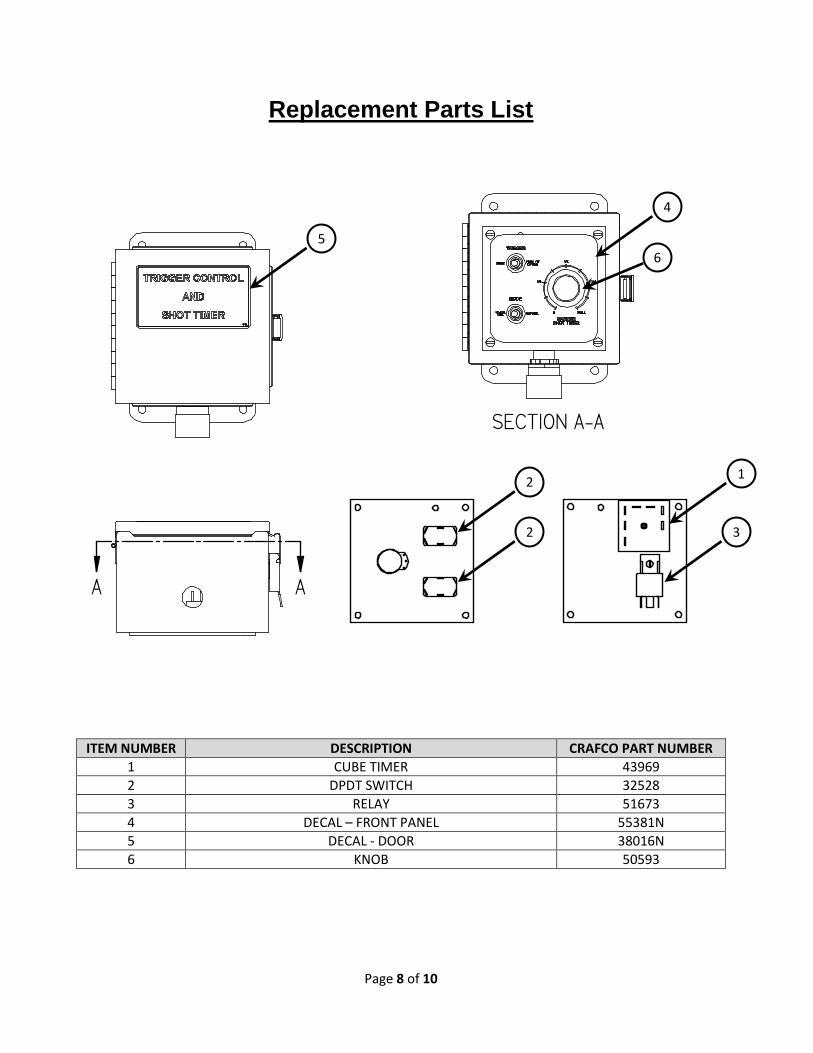
Replacement Parts List
A A
SECTION A-A
ITEM NUMBER DESCRIPTION CRAFCO PART NUMBER
1 CUBE TIMER 43969
2 DPDT SWITCH 32528
3 RELAY 51673
4 DECAL – FRONT PANEL 55381N
5 DECAL - DOOR 38016N
6 KNOB 50593
1 2
2 3
4
5
6

Page 9 of 10
---THIS PAGE INTENTIONALLY LEFT BLANK---

Page 10 of 10