Embed Size (px)
Citation preview

Jurnal Tribologi 12 (2017) 18-37
Received 10 December 2016; received in revised form 15 January 2017; accepted 21 February 2017.
To cite this article: Shuhaib and Wani (2017). Self-lubricating tribological characterization of lead free Fe-Cu based
plain bearing material. Jurnal Tribologi 12, pp.18-37.
Self-lubricating tribological characterization of lead free Fe-Cu based plain
bearing material
Shuhaib Mushtaq*, M.F. Wani
Centre for Tribology, Department of Mechanical Engineering, National Institute of
Technology Srinagar, 190006 India. *Corresponding author: [email protected]
HIGHLIGHTS
Effect of Tin concentration on density.
Vickers hardness of 3.71GPa for higher wt. % of Tin and BN.
Lower coefficient of friction and higher wear resistance.
ABSTRACT
The negative impact of lead on environment and thereby its reciprocity on the health of mankind, there is a
growing emphasis on resisting the usage of lead in bearings. Owing to this, new bearing materials that
provide comparable tribological performance to that of lead containing alloys are being developed. In this
study, lead free Fe-Cu based powders with addition of elements such as tin, molybdenum disulfide and
Nano boron nitride (BN) have been developed by powder metallurgy (PM) technique in order to improve
the tribological and mechanical properties. The powder mixtures were compressed at a pressure of 500
MPa, and then sintered in dry hydrogen atmosphere at 9000C for 50 minutes. The mechanical and
tribological properties obtained due to addition of the said elements is presented in this study. The
tribological behavior of the selected alloys is analyzed by reciprocating-sliding tests under dry conditions.
The morphology of wear scars and the microstructure of the wear surfaces were investigated. The material
with 2.5 wt.% of Sn exhibited the highest value of hardness, the material with 7.5 wt.% of Nano BN
comparably shows the low coefficient of friction and wear rate as compared with 5 wt.% of Nano BN.
Keywords:
| Self-lubricating bearing | Fe-Cu alloy | Powder metallurgy | Friction | Wear |
© 2017 Malaysian Tribology Society (MYTRIBOS). All rights reserved.

Jurnal Tribologi 12 (2017) 18-37
19
1.0 INTRODUCTION
Bearing materials are required to possess desirable mechanical and tribological
properties, such as, low friction, low wear resistance, compatibility etc. Most of the
failures in the plain bearing are due to poor friction and wear of materials (Bushan,
1999). The latest industrial developments have made the performance of machines to be
more demanding. Thus, the bearings have to be designed more accurately for higher
productive of machines (Ram, 2016). In order to have less friction, low wear and easier
sliding, various liquid lubricants including oil, grease, and water are used. However,
liquid lubricants have usage difficulties in various applications for example, in food
industry liquid lubricants can’t be used directly in order to avoid contamination of food
items, or liquid lubricants sometimes require complicated housing design which increases
the overall cost and most of the lubricants can be used in limited operational temperatures
(Mott and Erdimer, 2004). As a result, there is a strong desire among bearing designers to
produce sliding bearings that successfully reduce friction without employing any liquid
lubricants. The desire promoted the development of self-lubricating sliding bearings,
which are independent of external lubrication. In these types of bearings, liquid lubricants
are replaced by self-lubricating materials. Self-lubricants are any solid materials that
show low friction without application of liquid lubricants. Graphite, molybdenum
disulfide and boron nitride (BN) predominantly used solid lubricants. Self-lubricating
plain bearings are widely used in various applications such as home appliances, small
motors, machine tools, aircraft and automotive accessories, instruments, farm and
construction equipment’s (Tufekci et al., 2006; Teisanu et al., 2003).
Self-lubricating bearings represent the oldest industrial application of the porous
materials obtained by using powder metallurgy (PM) technique. Technical and economic
advantages of the PM technique have enabled us to use a wide variety of new materials
and products with special characteristics (Buharu et al., 2010). PM is an important
alternative to produce metal products with advanced technologies from metal powders
(sometimes mixed with non-metallic powders) by pressing and sintering. PM technique
has become increasingly interesting for engineering parts manufacturers due to its
advantages which includes high productivity, minimum consumption of raw materials
and energy, efficient use of the initial metals, near net shape character and unique
capability of porous material production.
Various materials have been investigated and used in bearings. Lead (Pb)
containing materials such as Cu-Pb based materials have been extensively used due to
their low friction characteristics and excellent conformability and embedability behavior
of Pb (Gebretsadik et al., 2015). However, due to environmental issues and its lower
strength, the use of Pb in bearings is being restricted. Various Pb free bearing materials
have been investigated which showed better wear resistance compared with lead based
materials.

Jurnal Tribologi 12 (2017) 18-37
20
In the modern research environment, there has been a rapid growth in the
development of engineering materials worldwide during the past few decades. In the
development of new materials, issues of material conservation, energy conservation,
longevity etc. has become a challenging task before designers, engineers and material
scientists (Omrani et al., 2016). In recent years, iron-based sintered bearings production
was considerably increased in industries at the expense of copper- based ones, due to the
low cost and availability of the iron powders, as well as their high strength. The
mechanical properties of the parts are strongly related to the composition of the material.
Sintered iron- based materials were not developed until the last decade because of their
poor corrosion resistance and antifriction properties. Considering the low cost and
availability of iron, additions such as copper, graphite, manganese, lead, phosphorous and
tin to iron have been attempted, but improvement in one property was offset by decrease
in other properties (Gheorghe et al., 2011; Kostornoy et al., 2007).
The novelty of the present study is the ferrous material containing iron as the
prime constituent, which plays a significant role in engineering applications due to its low
cost, ease of manufacture, better strength, toughness, ductility and availability. These
materials can be alloyed and heat treated to achieve desired mechanical properties. The
self-lubricating properties of ferrous based materials are reported less in the literature and
iron can be alloyed with other metals in order to change the microstructure so that the
properties for a given application can be easily met. Pre-alloyed ferrous powders, when
used with additive such as copper, tin etc. results in high strength martensitic
microstructure (Causton et al., 1992).
The objective of the present research study is to develop and fabricate Fe-Cu
based self-lubricating plain bearing material. In the present study Nano BN, is used as a
solid lubricant to study the friction and wear properties of Fe-Cu based developed
material, under dry conditions. BN is very similar to graphite in properties, the firm
binding of electrons by nitrogen makes boron nitride superior to graphite. It has high
thermal conductivity, low thermal expansion, good thermal shock resistance, high
electrical resistance and low dielectric constant. BN is also non-toxic, easy to machine,
non-abrasive and lubricious. It is chemically inert and is non-wetted by most molten
metals (Bernard et al., 2014). This objective will be achieved, by first of all, to find the
appropriate wt. % of Sn for proper sintering and determining the appropriate wt. % of BN
for achieving the self-lubricating property.
Jurnal Tribologi 12 (2017) 18-37
21
2.0 EXPERIMENTAL PROCEDURE
2.1 Materials
In this study, the iron (Fe) powder, used as a base material, was procured from
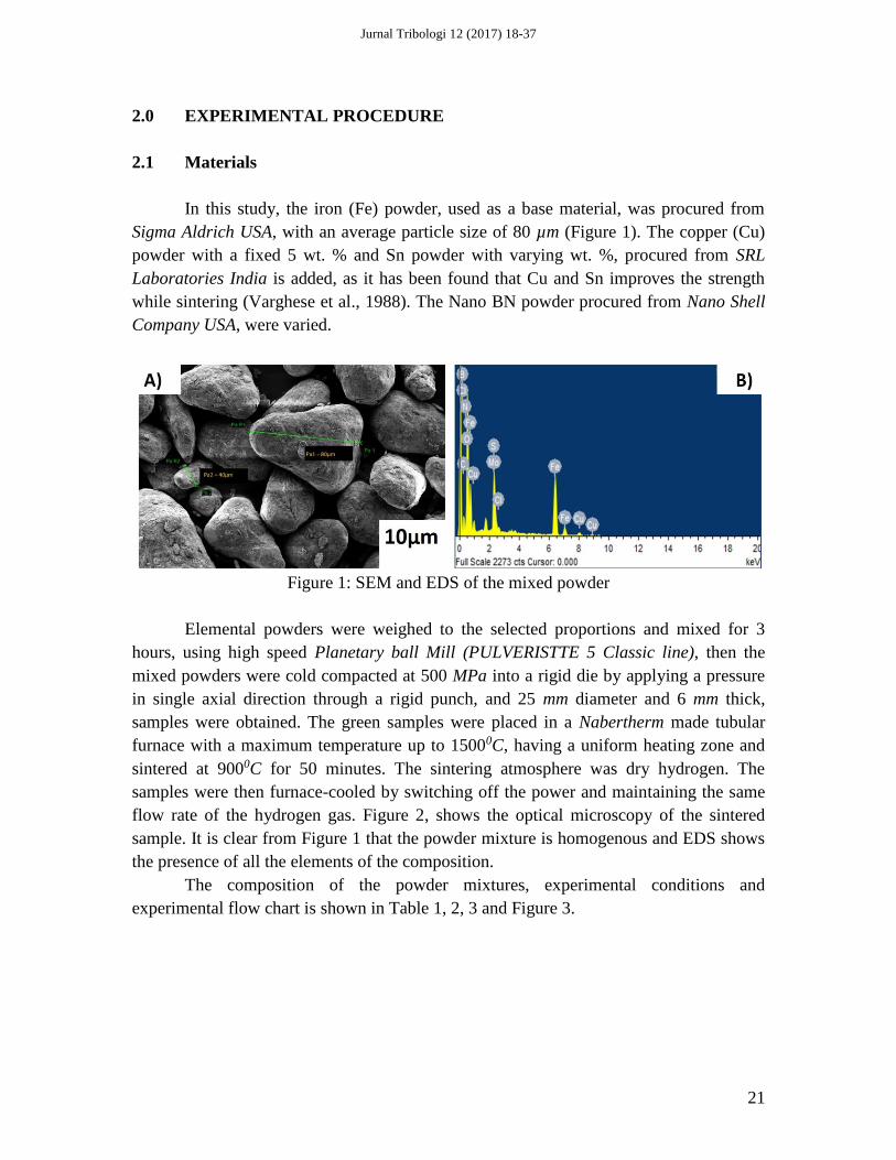
Sigma Aldrich USA, with an average particle size of 80 µm (Figure 1). The copper (Cu)
powder with a fixed 5 wt. % and Sn powder with varying wt. %, procured from SRL
Laboratories India is added, as it has been found that Cu and Sn improves the strength
while sintering (Varghese et al., 1988). The Nano BN powder procured from Nano Shell
Company USA, were varied.
Figure 1: SEM and EDS of the mixed powder
Elemental powders were weighed to the selected proportions and mixed for 3
hours, using high speed Planetary ball Mill (PULVERISTTE 5 Classic line), then the
mixed powders were cold compacted at 500 MPa into a rigid die by applying a pressure
in single axial direction through a rigid punch, and 25 mm diameter and 6 mm thick,
samples were obtained. The green samples were placed in a Nabertherm made tubular
furnace with a maximum temperature up to 15000C, having a uniform heating zone and
sintered at 9000C for 50 minutes. The sintering atmosphere was dry hydrogen. The
samples were then furnace-cooled by switching off the power and maintaining the same
flow rate of the hydrogen gas. Figure 2, shows the optical microscopy of the sintered
sample. It is clear from Figure 1 that the powder mixture is homogenous and EDS shows
the presence of all the elements of the composition.
The composition of the powder mixtures, experimental conditions and
experimental flow chart is shown in Table 1, 2, 3 and Figure 3.

Jurnal Tribologi 12 (2017) 18-37
22
Figure 2: Optical microscopy of the sintered sample at 100 µm and 10 µm
Table 1: Composition of the powder mixtures in weight percentage
Sample Fe Cu Sn MoS2 hBN
A Bal 5 1 1 2.5
B Bal 5 1.5 1 5
C Bal 5 2.5 1 7.5
Table 2: Experimental Conditions
Sintering Conditions
Sintering temperature (0C)
Holding time (min.)
Atmosphere
900
50
Dry Hydrogen
Table 3: Density values of sintered mixtures
Sample Bulk Density
(g/cm3)
Theoretical Density
(g/cm3)
Relative Density
(%)
A 6.4 6.5 98.46
B 6.5 6.8 95.58
C 6.8 7.3 93.15
Figure 3: Flow chart for experimental procedure

Jurnal Tribologi 12 (2017) 18-37
23
2.2 Characterization
The worn surfaces (wear tracks) of the test specimen with different test conditions
were studied under FESEM Quanta 200FEG scanning electron microscope (SEM) to
understand the mode of damage and wear mechanism. The analysis was also conducted
by energy-dispersive X-ray spectrometer (EDS) of oxford instrument (Model-51-
ADD0048) attached with ZEISS (Model-EVO 18) SEM to conform the presence of
elements under different operating conditions.
SEM with EDS results are shown in Figure 4 (a, b, c, d). It can be seen from
Figure 4, that these microstructures emphasize a relatively uniform distribution of the
phases in the ferrite matrix, with distinctive boundaries. EDS analysis of the Fe-Cu alloy
was carried out at four different spots marked as spectrum 1-4 which shows the presence
of all the constituents mixed with the base material Fe, shown in Figure 4 (a-d). It is
evident from EDS analysis of these four spots, the mixed composition is evenly
distributed over the surface of Fe-Cu alloy.
2.3 Density and Hardness
Bulk density of sintered samples was measured by using well known Archimedes’
method, full density achievement of powdered metallurgy samples is quite difficult,
because they comprises of pores. Bulk density is calculated by measuring the dry weight
of sample, suspended weight of sample and soaked weight of sample. It becomes
necessary to calculate relative density, which actually tells how much densification is
achieved. Relative density is the ratio of the bulk density to theoretical density.
Theoretical density of composite is calculated by rule of mixtures, based on the starting
composition, assuming no reaction and no impurities in the sintered materials (ASTM,
2002). Densities of the sintered samples is shown in Table 3.
Hardness tests were performed on polished surfaces (mirror like finish) using
Vickers indenter. Vickers hardness (HV) tests were performed on (INNOVATEST Falcon
500) micro hardness tester. The indentation was observed under 10X and 40X
magnification. HV were measured to study influence of indentation load on the hardness
values. The indentation load was varied from 10 g (0.098 N) to 300 g (2.94 N) and
indentation time was varied from 1 seconds to 10 seconds. The hardness reported here
was the mean value of five times tested.

Jurnal Tribologi 12 (2017) 18-37
24
Figure 4: SEM and EDS of Fe-Cu alloy (A, B, C, D shows the EDS at point 1-4)
2.3 Friction and Wear Tests
The tribological tests were carried out on reciprocating sliding testing machine
[Magnum Bangalore India] made, under dry conditions by Pin-on-Disc test, using a
testing device for friction Coefficient and wear rate measurements. Figure 5 shows the
schematic view of the reciprocating sliding (Pin-on–Disc) tester. The pin material chosen
for testing is of EN8 mild steel, hardness (HV) 4.31 GPa, and surface roughness (Ra 0.01
µm), rectangular in shape with dimensions of (3×2) mm and 15 mm height as shown
Figure 5. EN8 is widely used for many general engineering applications as shafts, studs,
bolts etc. The wear loss was weighed by an electronic balance with accuracy of ±0.0001
g. The testing was carried out at a load of 10,20,30 and 40 N with sliding velocity of
0.026m/s and sliding distance from 90,180,270,360 and 450 m at 500C temperature and
sliding time of 60 min. The two main factors which have high impact to the friction force

Jurnal Tribologi 12 (2017) 18-37
25
and wear value are speed and load. The context of friction is the force resisting the
relative motion of solid surface, fluid surface and material elements sliding against each
other. The other consequence which may lead to performance degradation or damage to
the components is the relationship between friction and wear (Nuraliza et al., 2016).
Before each test, the samples were polished (mirror like finish) using various grades of
abrasive papers, diamond paste of sizes 3 µm, 1.5 µm and 1 µm and then cleaned with
acetone followed by drying. Each specimen (Ra 0.30 µm) was weighed before and after
the test. All tribological tests were carried out three times to make sure the repeatability
of experimental data at the same testing condition. Wear of disc and pin was calculated in
terms of the specific wear coefficient (Kw) (Archard, 1953).
Figure 5: Schematic view of the reciprocating friction (Pin-on-Disc) tester
The specific wear coefficient is obtained as
Kw = mm3N-1m-1 (1)
Where Wv is wear volume, FN is normal load and Sd is sliding distance.
The operating parameters adopted for friction and wear measurements were as follows:
Normal load(s) (FN) = 10 N, 20 N, 30 N and 40 N
Sliding velocity = 0.026 m/s
Sliding distance (S d) = 90, 180,270,360,450 m
Temperature (T) = 500C and
Relative humidity (RH) = 55 %

Jurnal Tribologi 12 (2017) 18-37
26
3.0 RESULTS AND DISCUSSION
3.1. Density and Hardness
Density measurements carried out as per the standard on the sintered samples (A,
B and C) is shown in Table 3. Figure 6, indicates the decrease in relative density with
increase in wt. % of Sn. This behavior is attributed to the formation of Cu-Sn, Fe-Cu, and
Fe-Sn compounds in large amounts at higher temperatures as the Sn content increases
(Gheorghe et al., 2011).
Figure 6: Variation of relative density with different weight percentage of tin
The average of hardness values (HV) verses load measured in the as-sintered
samples (A, B and C) is shown in Figure 7. As can be seen in Figure 7, the hardness
decreases with the increase in load. However, higher hardness values were obtained in
sample C containing 2.5 wt. % Sn as compared with another samples A and B containing
1 and 1.5 wt. % Sn respectively. This behavior is attributed to the formation of Cu-Sn,
Fe-Cu, and Fe-Sn compounds in large amounts at higher temperatures as the Sn content
increases. Liquid Sn has substantial solubility in the solid iron, which aids in the
formation of liquid phase during sintering, which on solidification produces some
strengthening phases such as Fe-Sn, Fe-Cu, and Cu-Sn. Figure 8 (a & b) shows the
Vickers indentation images. The Figure 8a shows the indentation image at 0.98 N (10 g)
load and Figure 8b shows the indentation image at more than 2.94 N (300 g) load, which
clearly shows the development of cracks at load more than 2.94 N.

Jurnal Tribologi 12 (2017) 18-37
27
Figure 7: Vickers Hardness (HV) verses load (N) for samples A, B, and C containing 1,
1.5, and 2.5 wt. % Sn
Figure 8: Vickers Indentation (HV) at (A) 0.98 N load (B) 2.94 N load showing the
cracks developed

Jurnal Tribologi 12 (2017) 18-37
28
3.3 Friction and Wear Properties
Variation of friction coefficient of samples with different normal loads at a sliding
speed of 0.026 m/s under dry sliding condition is given in Figure 9. It can be noted that
the friction coefficient of samples B & C decreases with increasing applied load.
However, the friction coefficient of sample A at 20 N shows a fluctuation with increasing
applied load. In general, the friction coefficient of sample C decreases with increasing the
normal load. The sample B also shows the decrease in coefficient of friction with
increasing in load, but compared with sample C, shows higher coefficient of friction.
Figure 10 gives the variation of friction coefficient of samples with sliding distance at a
normal load of 30 N under dry sliding condition. It can be seen from Figure 10, that the
coefficient of friction of samples shows a large fluctuation at different sliding distances.
The coefficient of friction of samples A, B & C, there is a fluctuating trend of increase
and decrease in coefficient of friction upto 270 m sliding distance. With increase in
sliding distance from 270 m to 450 m, there is a decrease in coefficient of friction in all
the three samples. This may be related to the breaking and removal of surface oxide layer
leading to the metal-to-metal contact causes an increase in the coefficient of friction, with
further increase in sliding distance a steady state is reached and coefficient of friction
reduces marginally. This conclusion is also found from Fe-C-Cu alloy containing
molybdenum disulfide (Dhanasekaran et al., 2007). According to the above obtained
data, the sample C containing 7.5 wt.% of BN shows the decreased friction coefficient in
comparison with sample B and A containing 5 and 2.5 wt. % of BN during the sliding
process.
Figure 9: Variation of friction coefficient of samples at different applied loads (0.026
m/s, 60 min.)

Jurnal Tribologi 12 (2017) 18-37
29
Figure 10: Variation of friction coefficient of samples at different sliding distance (30 N,
60 min.)
Figure 11 presents the variation of specific wear coefficient ‘K’ of samples with
different normal loads at a sliding speed of 0.026 m/s under dry sliding condition. The
specific wear coefficient of sampless A, B & C is higher between the normal loads of 10
N to 20 N and then reduces with the increase in load from 20N to 40N. The transfer layer
at high loads is more continuous in comparison with that at low loads, which decreases
the contact area of metal to metal. The samples containing 5 wt. % and 7.5 wt. % of BN
shows the low specific wear coefficient at higher normal loads. The specific wear
coefficient of samples A, B & C is of the order of 10-4 mm3/Nm (see Figure 11). It is clear
from the Figure 11, that the wear coefficient in specimen C containing higher wt. % of
BN is about two times lower than the sample A containing 2.5 wt. % of BN. Figure 12,
gives the variation of specific wear coefficient of samples with different sliding speeds at
a normal load of 30 N under dry sliding condition. It can be noted that the specific wear
rate of samples decreases with the increase of sliding distance. The specific wear rate of
samples A, B & C is of the order of 10-4 mm3/Nm. The specific wear coefficient of
specimen C is lower than the samples A and B. In general, the specific wear coefficient
decreases with increasing weight percent of BN.
All our results prove that hexagonal Boron Nitride (hBN) is an effective solid
lubricant. The reason for this is that the BN particles can smear out from the matrix and
act as a solid lubricant during the sliding process. These BN particles can form a smeared
layer on the worn surface, which becomes dense with the increase of BN content. The
BN rich mechanical mixed layer (MML) changed the contact model between the disc and
pin in order that the direct contact area was decreased, and therefore reducing the friction
coefficient and improving the wear resistance of Fe-Cu-Sn-MoS2-BN composite under

Jurnal Tribologi 12 (2017) 18-37
30
different applied loads and sliding speeds (Cui et al., 2012). According to the empirical
Archard’s equation, already reported as equation (1), the wear resistance of materials is
proportional to the hardness of composites. The hardness of sample C containing 2.5
wt. % Sn and 7.5 wt. % BN is higher (see Table 3) than samples B & A resulting in the
lower specific wear rate of C.
Figure 11: Variation of specific wear coefficient of samples at different applied loads
(0.026 m/s, 60 min.)
Figure 12: Variation of specific wear coefficient of samples at different sliding distances
(0.026 m/s, 60 min.)

Jurnal Tribologi 12 (2017) 18-37
31
3.3.2 Evaluation of Worn Surfaces
Figure 13 and 14 show the SEM & EDS images of morphologies of wear scars of
samples at 30 N normal load and different sliding distances. As is seen from the figures,
wear debris, fracturing, plough, and plastic deformation are noted on the worn surfaces of
sample A. The sample B & C shows the less ploughing as the EDS of Figure 13 (b, c)
shows the higher value of BN as compared with Figure 13a. The BN was squeezed out
from the subsurface due to the effect of tribological stress and the BN would spread on
the worn surface and mixed with other debris. Finally, these actions resulted in the
formation of BN-rich MML (Mahathanabodee et al., 2013; Goncalves et al., 2014). It
indicates that the wear mechanism of sample A is adhesive and abrasive wear. From the
hardness and wear resistance relation perspective, the subsurface of sample A easily
deformed due to stress as cracks and fracture can be seen in Figures 13a and 14a. The
BN-rich MML was not stable in order that the discontinuous BN-rich MML on the entire
worn surface of sample A was noted. It means that the wear mechanism of sample A is
abrasive wear and delamination at testing conditions. It can have been seen from the
figures that the micro plough is noted on the worn surfaces of samples and the worn
surfaces of samples B & C are relatively smooth in comparison with the worn surface of
sample A at the same testing condition. The high hardness of sample C as seen from
Table 3, a continuous boron rich layer is noted on the worn surface. On the worn surface
of sample A, an incomplete boron rich layer is noted. The fresh matrix is exposed on the
worn surface during the sliding process and suffered from wear, and therefore the sample
A, keeps a high specific wear rate.

Jurnal Tribologi 12 (2017) 18-37
32
Figure 13: SEM and EDS of samples A, B & C tested at 30 N normal load

Jurnal Tribologi 12 (2017) 18-37
33
Figure 14: SEM and EDS of samples A, B & C tested for sliding distance at 30 N normal
load
The worn surface of EN8 pin after tribotesting against the disc at 0.026 m/s and
30 N are shown in Figure 15 a and b. Because the hardness of EN8 pin is higher than the
disc, the Fe, Cu, hBN etc., is transferred to the EN8 Pin (see Figure15b EDS). This often
observed from the case when a softer material slides against a harder material
(Mahdavian et al., 1982). The transfer layer play an important role in influencing the
tribological properties of the composites. The Figure 15a, depict the worn surface of the

Jurnal Tribologi 12 (2017) 18-37
34
EN8 pin sliding against sample C. The boron rich layer of sample C covered the worn
surface of pin. This tribolayer prevents the wear of EN8 pin, which also plays an
important part in reducing the friction coefficient and specific wear rate of composites.
Figure 15: (A) SEM of EN8 pin showing material removal and adhesion of material from
disc (B) SEM and EDS showing the material on pin
Raman spectra of sample C on the worn surface under dry sliding condition is
shown in Figure 16. Due to the sliding of the EN8 pin during the sliding process, the
temperature of the worn surfaces rose in order that the material could react with
environment oxygen. Oxides at the contact surfaces could form on the worn surface (Jia
et al., 2004, Rajkumar et al., 2011; Moustafa et al., 2002). It is clear from the Figure 16,
that the Fe, Mn oxides can be seen with the main peak positions as 210, 275, 392 and
with the chemical formula Fe3+O (OH).

Jurnal Tribologi 12 (2017) 18-37
35
Figure 16: Raman spectra of sample C
CONCLUSION
Fe-Cu based composite with addition of elements such as Sn, MoS2 and Nano BN
was developed as a self-lubricating material for plain bearings using powder metallurgy
technique, sintered under controlled atmosphere. Mechanical and tribological tests were
conducted on the Fe-Cu based composites by Pin-on-Disc (reciprocating sliding) using
EN8 pin under dry conditions to access the mechanical and tribological properties of
these composites. The following results were obtained:
a) The relative density of the composite decreases with the increase in the wt. %
of the Sn content. This behavior is attributed due to the formation of Cu-Sn,
Fe-Cu and Fe-Sn compounds in large amounts at higher temperature as the Sn
content increases.
b) The composite containing 2.5 wt. % Sn and 7.5 wt. % of Nano BN shows the
higher value of Vickers hardness, as the indentation load is varied from 10 g
(0.098 N) to 300 g (2.94 N) on HV. The higher HV value obtained is
3.71GPa.
c) Nano BN acts as a lubricant under dry sliding conditions between the Fe-Cu
based composite and EN8 pin tribo pair at 50 0C temperature.
d) The highest value of Coefficient of friction (0.26-0.32) is obtained in
composite containing low content of Nano BN as compared with the
composite containing higher wt. % of Nano BN, showing the low value of
Coefficient of friction.

Jurnal Tribologi 12 (2017) 18-37
36
e) The composite containing 7.5 wt. % of Nano BN shows the higher wear
resistance as the hardness value is higher as compared with other composites
containing lower wt. % of Nano BN.
ACKNOWLEDGEMENTS
The authors wish to acknowledge the kind support by Prof. D. Sarkar, National
Institute of Technology Rourkela, India for helping me in sample preparation, MHRD
India for financial assistance and Centre for tribology, National Institute of Technology,
Srinagar, India where the work was performed.
REFERENCES
Ali Erdemir. Solid lubricants and Self- lubricating films, 2001. CRC Press LLC
Archard, J., 1953. Contact and rubbing of flat surfaces. Journal of applied physics, 24(8),
981-988.
ASTM international designation, 2002. B 108, 328-96.
Bernard, S. and Miele, P., 2014. Nanostructured and architecture boron nitride from
boron, nitrogen and hydrogen-containing molecular and polymeric precursors.
Materials Today, 17, 443-450.
Buharu, M., Bicsak, E. and Sorcoi, L.A., 2010. Properties of sintered parts obtained from
Fe based powders produced by ductil iron powder. BUZAU Romania.
Bushan, B., 1999. Principles and Applications of Tribology. John Wiley & Sons.
Causton, R.J. and Fulmer, J.J., 1992. Sinter hardening low-alloy steels. Advances in
Powder Metallurgy and Particulate Materials, vol.5, 17-51.
Cui, G., Niu, M., Zhu, S., Yang, J. and Bi, Q., 2012. Dry-sliding tribological properties of
bronze-graphite composites. Tribology letters, 48 (2), 111-122.
Dhanasekaran, S. and Gnanamoorthy, R., 2007. Dry sliding friction and wear
characteristics of Fe-C-Cu alloy containing MoS2. Materials and Design, 28, 1135-
1141.
Gebretsadik, D.W., Hardell, J. and Prakash, B., 2015. Friction and wear characteristics of
different Pb - free bearing materials in mixed and boundary lubrication regimes,
Wear, 340-341, 63-72.
Gheorghe, S. and Teisanu, C., 2011. Development of New PM Iron-Based Materials for
Self-lubricating Bearings. Advances in Tribology, 11-16.
Goncalves, P.D., Furlan, K.P., Hammes, G., Binder, C. and Klien, A.N., 2014. Self-
lubricating sintered composites with h-BN and Graphite mixtures as solid lubricants,
in world congress on powder metallurgy and particulate materials, Orlando, 9.10-
9.17.
Jurnal Tribologi 12 (2017) 18-37
37
Jia, J.H., Chen, J.M., Zhou, H.D., Wang, J.B. and Zhou, H., 2004. Friction and wear
properties of bronze-graphite composite under water lubrication. Tribology
International, 37,423-429.
Kostornoy, A.G. and Fushchich, O.I., 2007. Sintered Antifriction Materials. Powder
Metallurgy and Metal Ceramics, 46, 9-10.
Mahathanabodee, S., Palathai, T., Raadnui, S., Tongsri, R. and Sombatsompop, N., 2013.
Effects of hexagonal boron nitride and sintering temperature on mechanical and
tribological properties of SS316L/h-BN composites. Materials and Design, 46, 588-
597.
Mahdavian, S.M., Mai, Y.W. and Cotterell, B., 1982. Friction, metallic transfer and
debris analysis of sliding surface. Wear, 82, 221-232.
Moustafa, S.F., El-Badry, S.A, Sanad, A.M. and Kieback, B., 2002. Friction and wear of
copper-graphite composites made with Cu-coated and uncoated graphite powders.
Wear, 253, 699-710.
Nathi R., 2016. Performance of non-recessed hole- entry hybrid journal bearing operating
under turbulent regime. Jurnal Tribologi, 8, 12-26.
Nuraliza, N., Syahrullail, S. and Faizal, M.H., 2016. Tribological properties of aluminium
lubricated with palm olein at different load using pin-on-disk machine. Jurnal
Tribologi, 9, 45-59.
Omrani, E., Moghadam, A.D., Menezes. P.L. and Rohatgi, P.K., 2016. New emerging
self-lubricating metal matrix composites for tribological applications. Ecotribology,
Springer International Publishing, 63-103.
Rajkumar, K. and Aravindan, S., 2011. Tribological performance of microwave sintered
copper –TiC-graphite hybrid composites. Tribology International 44, 347-358.
Robert, L. Mott, Machine Elements in Mechanical Design.4th Edition. Pearson Prentice
Hall, 660-687.
Teisanu, C., Tudor, A. and Ciupitu, I., 2003. Tribological features of PM Iron-Copper
based materials. Fascicle VIII, Tribology, 1221-4590.
Tufekci, K., Kurbanoglu, C. and Tunay, R., 2006. Friction and wear properties of Cu and
Fe based P/M bearing materials. Journal of Mechanical Science and Technology, 27
(4), 513-521.
Verghese, R. and Gopinath, K., 1988. The influence of Antimony additions on Sintered
Fe-Cu bearing materials. Key Engineering Materials, 29-31, 457-464.