Embed Size (px)
Citation preview
1
SI Engine Combustion
Spark discharge characteristics
Fig.9-39Schematic of voltage and current variation with time for conventional coil spark-ignition system.
2
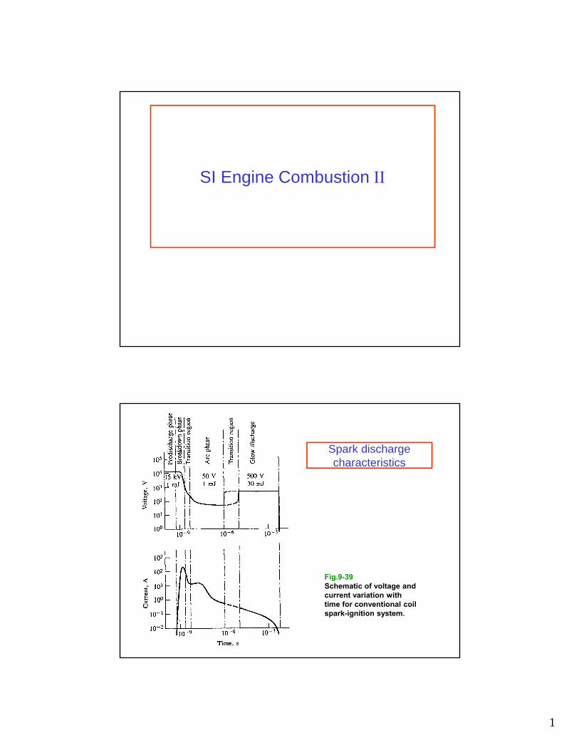
Flame Kernel Development (SAE Paper 880518)
Single cycle flame sequenceFlame from 4 consecutive cycles at fixed time after spark
=1, spk= 40oBTC,1400 rpm, vol. eff. = 0.29
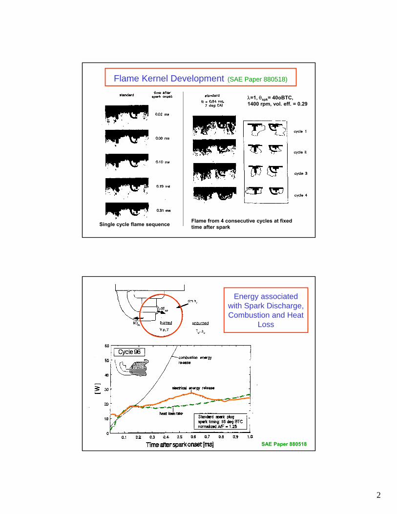
Energy associated with Spark Discharge, Combustion and Heat
Loss
SAE Paper 880518

3
Ignition and Flame Development Process
1. Spark discharge creates a high temperature plasma kernel which expands rapidly (1mm, 100 s).
2. The hot reactive gas at the outer edge of this kernel causes the adjacent fuel-air mixture to ignite, creating an outward propagating flame which is almost spherical.
3. As the flame grows larger, the flame surface is distorted by the turbulence of the fluid motion. A wrinkled laminar flame results.
4. Because of the significant surface area enhancement by the wrinkling, the locally laminar “turbulent” flame burns rapidly.
Schematic of entrainment-and-burn model
Fig. 14-12

4
SI engine flame propagationEntrainment-and-burn model
Rate of entrainment:
Rate at which mixture burns:
bt /eu f L u f T
dmA S A u (1 e )
dt
Laminar diffusion through flame front
Turbulent entrainment
L
Tb
b
beLfu
b
S ;
mm SA
dt
dm
Laminar frontal burning Conversion of entrained mass into burned mass
Critical parameters: uT and T
SI Engine design and operating factorsaffecting burn rate
1. Flame geometry:The frontal surface area of the flame directly affects the burn rate. This flame area depends on flame size, combustion chamber shape, spark plug location and piston position.
2. In-cylinder turbulence during combustion:The turbulence intensity and length scale control the wrinkling and stretching of the flame front, and affect the effective burning area. These parameters are determined largely by the intake generated flow field and the way that flow changes during compression.
3. Mixture composition and state:The local consumption of the fuel-air mixture at the flame front depends on the laminar flame speed SL. The value of SL depends on the fuel equivalence ratio, fraction of burned gases in the mixture (residual plus EGR), and the mixture temperature and pressure.

5
Cycle-to-cycle variations
Crank angle (o ATDC) Crank angle (o ATDC)
Fig. 9-31Measured cylinder pressure and calculated gross heat-release rate for ten cycles in a single-cylinder SI engine operating at 1500 rpm, = 1.0, MAP = 0.7 bar, MBT timing 25oBTC
Cycle-to-cycle change in combustion phasing
6
SI ENGINE CYCLE-TO-CYCLE VARIATIONS
Phases of combustion1. Early flame development
2. Flame propagation
3. Late stage of burning
Factors affecting SI engine cycle-to-cycle variations:(a) Spark energy deposition in gas (1)
(b) Flame kernel motion (1)
(c) Heat losses from kernel to spark plug (1)
(d) Local turbulence characteristics near plug (1)
(e) Local mixture composition near plug (1)
(f) Overall charge components - air, fuel, residual (2, 3)
(g) Average turbulence in the combustion chamber (2, 3)
(h) Large scale features of the in-cylinder flow (3)
(i) Flame geometry interaction with the combustion chamber (3)
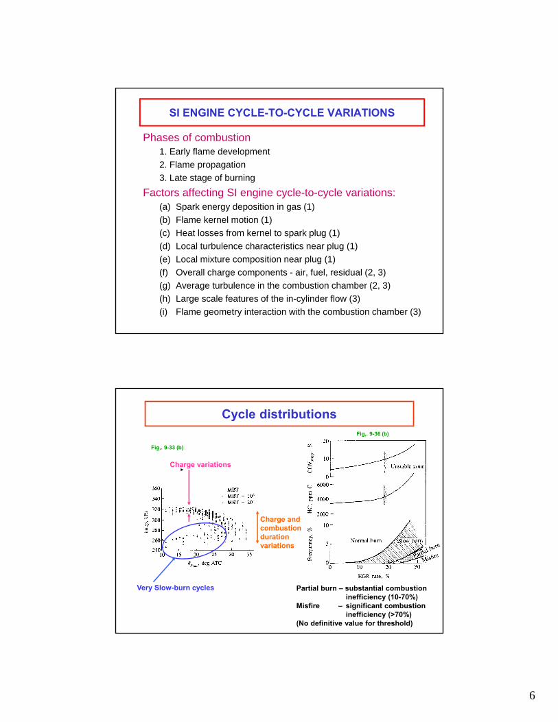
Cycle distributions
Charge variations
Charge and combustion duration variations
Very Slow-burn cycles Partial burn – substantial combustion inefficiency (10-70%)
Misfire – significant combustion inefficiency (>70%)
(No definitive value for threshold)
Fig,. 9-33 (b)
Fig,. 9-36 (b)
7
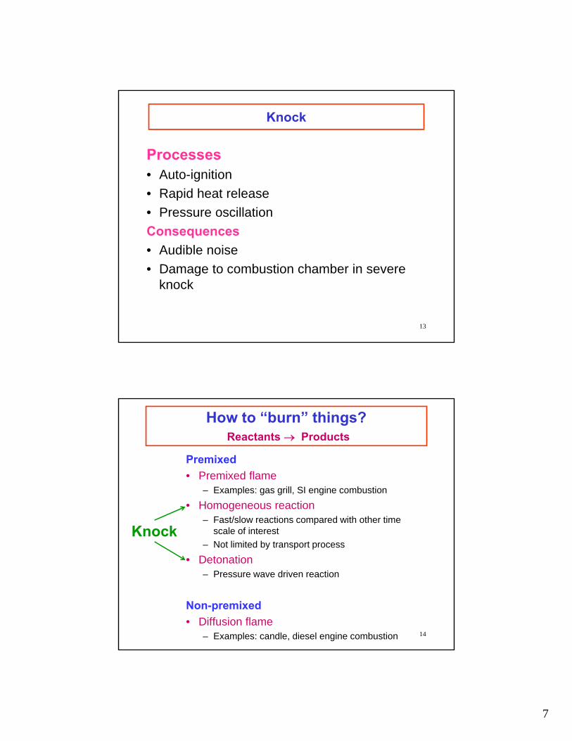
Knock
Processes• Auto-ignition
• Rapid heat release
• Pressure oscillation
Consequences
• Audible noise
• Damage to combustion chamber in severe knock
13
How to “burn” things?Reactants Products
Premixed
• Premixed flame– Examples: gas grill, SI engine combustion
• Homogeneous reaction– Fast/slow reactions compared with other time
scale of interest
– Not limited by transport process
• Detonation– Pressure wave driven reaction
Non-premixed
• Diffusion flame– Examples: candle, diesel engine combustion
Knock
14
8
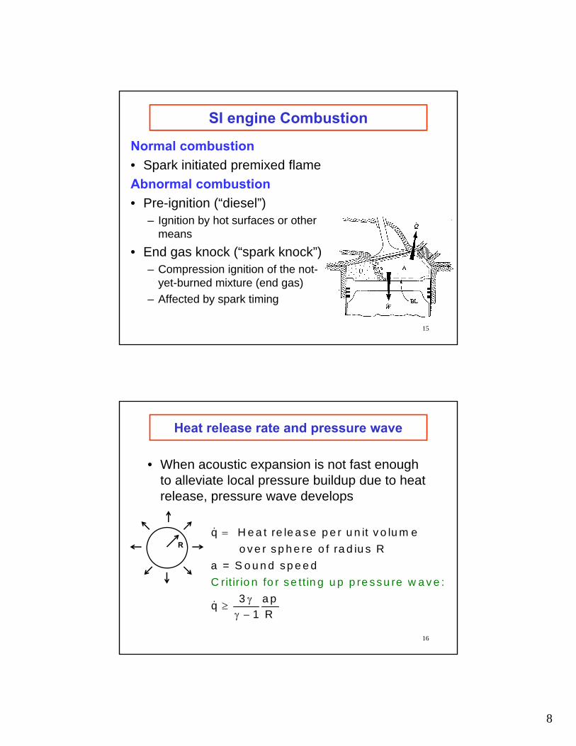
SI engine Combustion
Normal combustion
• Spark initiated premixed flame
Abnormal combustion
• Pre-ignition (“diesel”)– Ignition by hot surfaces or other
means
• End gas knock (“spark knock”)– Compression ignition of the not-
yet-burned mixture (end gas)
– Affected by spark timing
15
Heat release rate and pressure wave
• When acoustic expansion is not fast enough to alleviate local pressure buildup due to heat release, pressure wave develops
16
R
q H e a t re le a se p e r u n it v o lu m e
o v e r s p h e re o f ra d iu s R
a
C ritir io n fo r se ttin g u p p re ssu re w a
= S o u n d
v e :
sp e e d
3 a pq
1 R
9
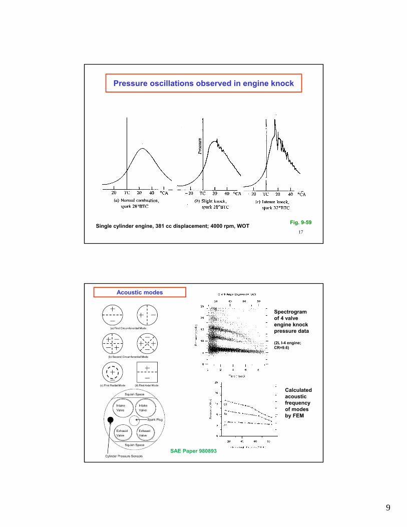
Pressure oscillations observed in engine knock
Fig. 9-59Single cylinder engine, 381 cc displacement; 4000 rpm, WOT
17
Acoustic modes
Spectrogram of 4 valve engine knock pressure data
(2L I-4 engine; CR=9.6)
Calculated acoustic frequency of modes by FEM
SAE Paper 980893
10
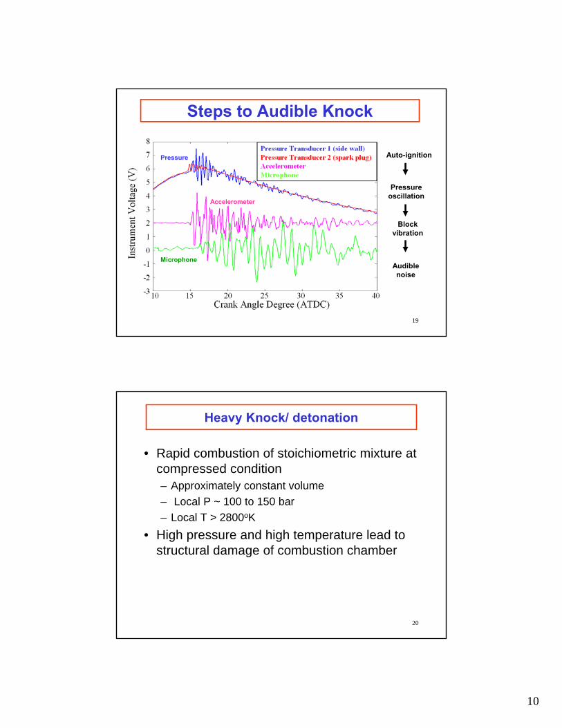
Steps to Audible Knock
Auto-ignition
Pressureoscillation
Blockvibration
Audiblenoise
Accelerometer
Microphone
Pressure
19
Heavy Knock/ detonation
• Rapid combustion of stoichiometric mixture at compressed condition– Approximately constant volume
– Local P ~ 100 to 150 bar
– Local T > 2800oK
• High pressure and high temperature lead to structural damage of combustion chamber
20
11
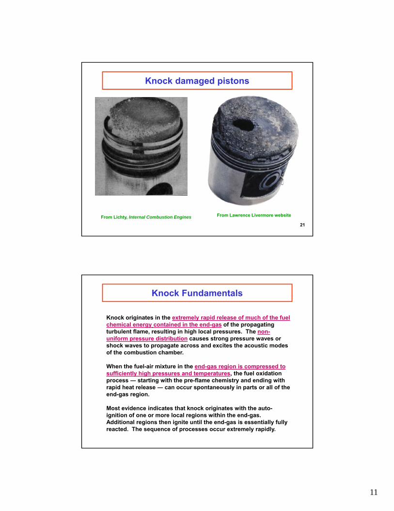
Knock damaged pistons
From Lawrence Livermore websiteFrom Lichty, Internal Combustion Engines
21
Knock Fundamentals
Knock originates in the extremely rapid release of much of the fuel chemical energy contained in the end-gas of the propagating turbulent flame, resulting in high local pressures. The non-uniform pressure distribution causes strong pressure waves or shock waves to propagate across and excites the acoustic modes of the combustion chamber.
When the fuel-air mixture in the end-gas region is compressed to sufficiently high pressures and temperatures, the fuel oxidation process ― starting with the pre-flame chemistry and ending with rapid heat release ― can occur spontaneously in parts or all of the end-gas region.
Most evidence indicates that knock originates with the auto-ignition of one or more local regions within the end-gas. Additional regions then ignite until the end-gas is essentially fully reacted. The sequence of processes occur extremely rapidly.

12
Knock chemical mechanism
CHAIN BRANCHING EXPLOSIONChemical reactions lead to increasing number of radicals, which leads to rapidly increasing reaction rates
etc. ,OROR
nPropagatio Chain
OHRORH
Initiation Chain
22
22
22
2
2
OHOCROCHOR
HOORROOH
Branching Degenerate
ORCHOROR
RROOHRHOR
Agents Branching of Formation
Ignition delay for primary reference fuels
24
0.8 1.0 1.2 1.4
0.1
1
10
1200 1100 1000 900 800 700
0.8 1.0 1.2 1.4
0.1
1
10
1200 1100 1000 900 800 700
Ign
dela
y (m
s)
1000/T[k]
ON=060
80
90
100
(Adapted from data of Fieweger et al, C&F 109)
P = 40 bar
T(oK)
Range of interest

13
Ignition delay kinetics
2
2
RH O
R HO
Initiation
Propagation Degenerate Branching
22R O RO
2
2
RO ROOH
ROOH O OOROOH
OOROOH O=ROOH OH
(Isomerization)
Branching agent (hydroperoxyl carbonyl species)
O=ROOH O=RO OH
2 2 2
2 2 2 2
RH HO R H O
HO HO M H O M
2 2H O M OH OH M
Branching agent (hydrogen peroxide)
Low temperature
High temperature
PropagationDegenerate Branching
NTC regimeTemperature high enough to shift formation of RO2 to H2O2, but not high enough for H2O2
decomposition
Livengood and Wu integral
265th Combustion Symposium, 1954
ignt
dt1
p(t),T(t)

14
FUEL FACTORS
• The auto-ignition process depends on the fuel chemistry.
• Practical fuels are blends of a large number of individual hydrocarbon compounds, each of which has its own chemical behavior.
• A practical measure of a fuel’s resistance to knock is the octane number. High octane number fuels are more resistant to knock.
Types of hydrocarbons(See text section 3.3)
15
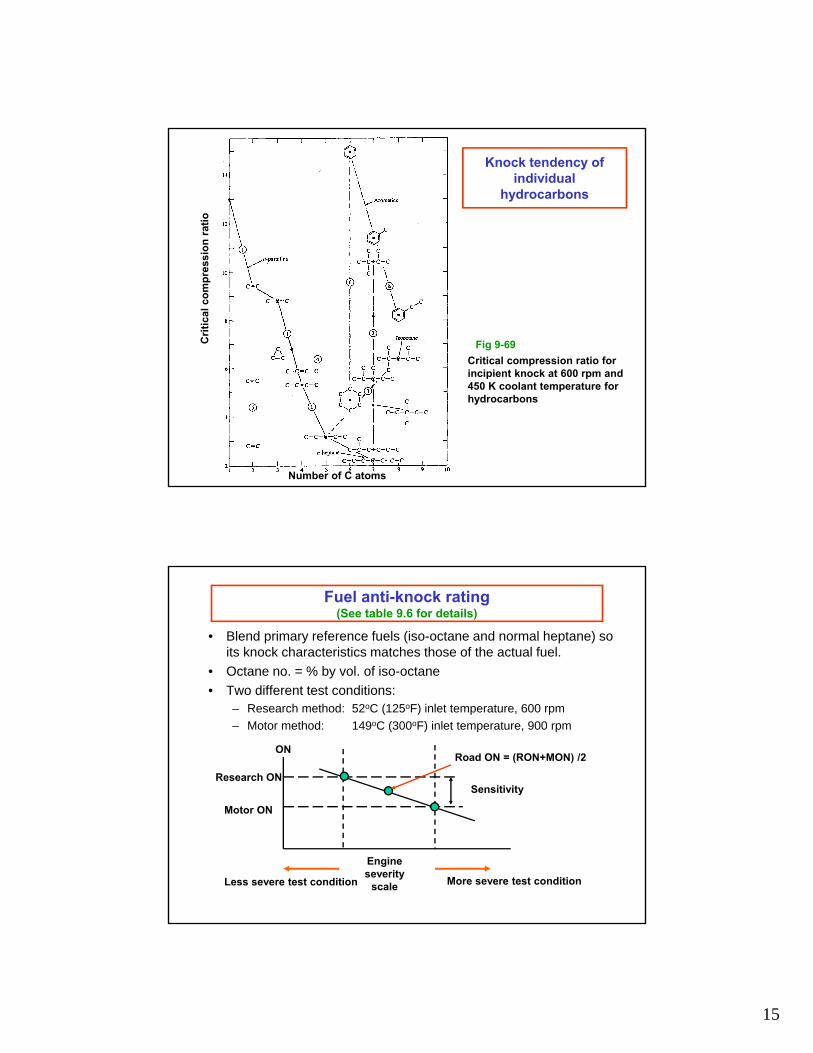
Knock tendency of individual
hydrocarbons
Number of C atoms
Cri
tica
l co
mp
ress
ion
rat
io
Critical compression ratio for incipient knock at 600 rpm and 450 K coolant temperature for hydrocarbons
Fig 9-69
Fuel anti-knock rating(See table 9.6 for details)
• Blend primary reference fuels (iso-octane and normal heptane) so its knock characteristics matches those of the actual fuel.
• Octane no. = % by vol. of iso-octane
• Two different test conditions:– Research method: 52oC (125oF) inlet temperature, 600 rpm
– Motor method: 149oC (300oF) inlet temperature, 900 rpm
Research ON
ON
Motor ON
Sensitivity
Engine severity
scale More severe test conditionLess severe test condition
Road ON = (RON+MON) /2

16
Octane requirement
Engine on test standCars on the road
From Balckmore and Thomas, Fuel Economy of the Gasoline Engine, Wiley 1977.
Slope 5
Octane Requirement Increase
Hours of operation
Oct
ane
Req
uir
emen
t in
crea
se (
OR
I)
0
Test 1 (no additive)
Test 2 (with additive)
Test 3 (with additive)
Deposit removal
No additive (ORI = 15)
Deposit controlling additive (ORI = 10)
Clean combustion chamber only
Clean combustion chamber and intake valves
ACS Vol. 36, #1, 1991

17
ONR with change of engine parameters
33
From SAE Paper 2012-01-1143
Knock control strategies
1. Provide adequate cooling to the engine
2. Use intercooler on turbo-charged engines
3. Use high octane gasoline
4. Anti-knock gasoline additives
5. Fuel enrichment under severe condition
6. Use knock sensor to control spark retard so as to operate close to engine knock limit
7. Fast burn system
8. Gasoline direct injection

18
Anti-knock Agents
AlcoholsMethanol CH3OH
Ethanol C2H5OH
TBA (Tertiary Butyl Alcohol) (CH3)3COH
EthersMTBE (Methyl Tertiary Butyl Ether) (CH3)3COCH3
ETBE (Ethyl Tertiary Butyl Ether) (CH3)3COC2H5
TAME (Tertiary Amyl Methyl Ether) (CH3)2(C2H5)COCH3
Adiabatic cooling of gasoline/ ethanol mixture
0.0 0.2 0.4 0.6 0.8 1.010
20
30
40
50
60
70
80
Tem
per
atu
re d
rop
(oC
)
Ethanol liquid volume fraction
Preparing a stoichiometric mixture from air and liquid fuel
36Note that Evaporation stops when temperature drops to dew point of the fuel in vapor phase
19
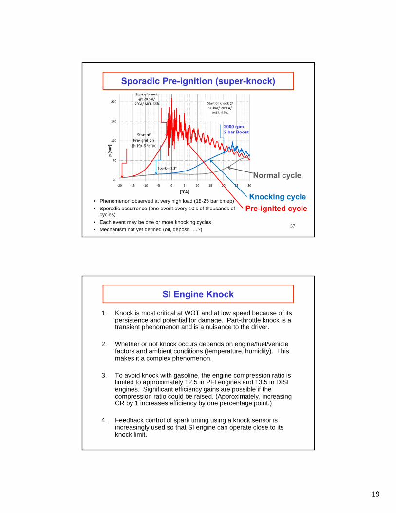
Sporadic Pre-ignition (super-knock)
• Phenomenon observed at very high load (18-25 bar bmep)
• Sporadic occurrence (one event every 10’s of thousands of cycles)
• Each event may be one or more knocking cycles
• Mechanism not yet defined (oil, deposit, …?)37
Normal cycle
Knocking cycle
Pre-ignited cycle
2000 rpm 2 bar Boost
SI Engine Knock
1. Knock is most critical at WOT and at low speed because of its persistence and potential for damage. Part-throttle knock is a transient phenomenon and is a nuisance to the driver.
2. Whether or not knock occurs depends on engine/fuel/vehicle factors and ambient conditions (temperature, humidity). This makes it a complex phenomenon.
3. To avoid knock with gasoline, the engine compression ratio is limited to approximately 12.5 in PFI engines and 13.5 in DISI engines. Significant efficiency gains are possible if the compression ratio could be raised. (Approximately, increasing CR by 1 increases efficiency by one percentage point.)
4. Feedback control of spark timing using a knock sensor is increasingly used so that SI engine can operate close to its knock limit.