Embed Size (px)
Citation preview
Reinforced and Prestressed
Concrete Design
according to SIA 262

The description of program functions within this documentation should not be considered a warranty of product features.All warranty and liability claims arising from the use of this documentation are excluded.
InfoGraph® is a registered trademark of InfoGraph GmbH, Aachen, Germany. The manufacturer and product namesmentioned below are trademarks of their respective owners.
This documentation is copyright protected. Reproduction, duplication, translation or electronic storage of this document orparts thereof is subject to the written permission of InfoGraph GmbH.
InfoGraph® Software uses Microsoft® MFC and Intel® MKL Libraries.
© 2019 InfoGraph GmbH, Aachen, Germany. All rights reserved.
Title image: Structural model of a prestressed three-span bridge
1
Contents
© InfoGraph GmbH, January 2019
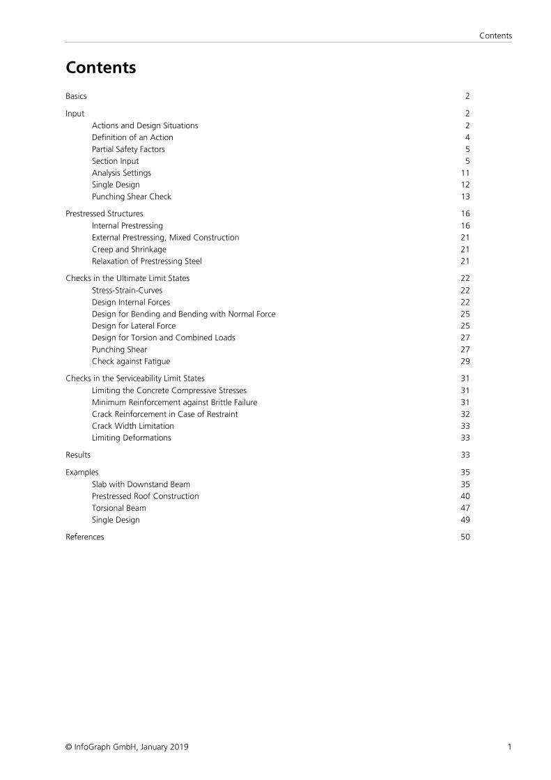
Contents
Basics 2
Input 2
Actions and Design Situations 2
Definition of an Action 4
Partial Safety Factors 5
Section Input 5
Analysis Settings 11
Single Design 12
Punching Shear Check 13
Prestressed Structures 16
Internal Prestressing 16
External Prestressing, Mixed Construction 21
Creep and Shrinkage 21
Relaxation of Prestressing Steel 21
Checks in the Ultimate Limit States 22
Stress-Strain-Curves 22
Design Internal Forces 22
Design for Bending and Bending with Normal Force 25
Design for Lateral Force 25
Design for Torsion and Combined Loads 27
Punching Shear 27
Check against Fatigue 29
Checks in the Serviceability Limit States 31
Limiting the Concrete Compressive Stresses 31
Minimum Reinforcement against Brittle Failure 31
Crack Reinforcement in Case of Restraint 32
Crack Width Limitation 33
Limiting Deformations 33
Results 33
Examples 35
Slab with Downstand Beam 35
Prestressed Roof Construction 40
Torsional Beam 47
Single Design 49
References 50
2
SIA 262 Design
© InfoGraph GmbH, January 2019
SIA 262 Design
BasicsThe reinforced concrete and prestressed concrete design according to SIA 262:2013 is applicable for both building andbridge structures. Permitted structure models include beam, area and solid constructions. Prestressed structures can only bechecked in the FEM module.
Differing components can be combined in a structure model:
• Non-prestressed components
• Prestressed components with subsequent bond
• Prestressed components without bond
• Components with external prestressing
• Mixed-construction components
The design is carried out after the static calculation. To do so, you need to assign the calculated load cases to the actions inaccordance with SIA 260. The program will take into account the preset safety factors and combination coefficients for thedesired design situations to automatically calculate the decisive design internal forces for either the entire system or a groupof selected elements.
The actions and check selection dialogs can be opened from the analysis settings. Detailed check specifications andreinforcement data must be entered during section definition.
The checks are limited to elements with materials SC12/15 to SC50/60, SLC12/13 to SLC50/55 and SCX..
For beams and design objects, all checks are carried out at the polygon section. For general notes on using design objects,refer to the relevant chapter of the manual.
In the SIA 262 Design folder of the database you can also perform a single design for user-defined polygon sections orcomposite sections.
Input
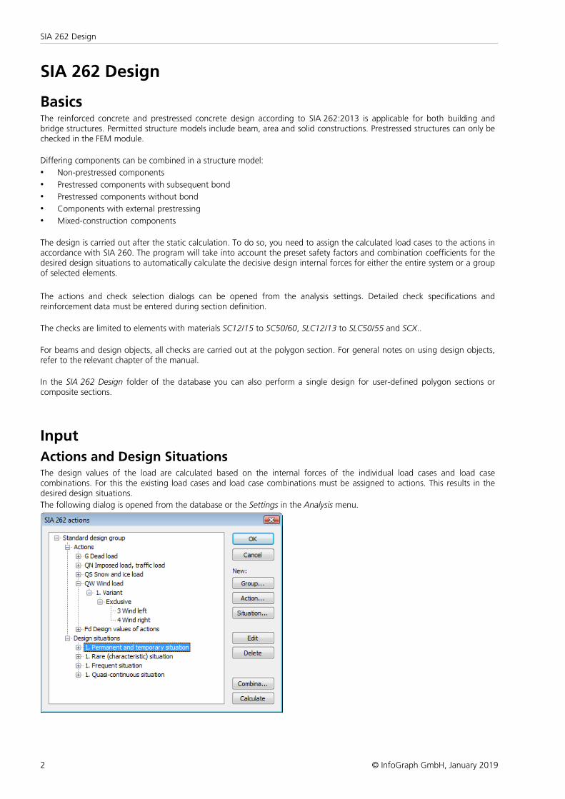
Actions and Design SituationsThe design values of the load are calculated based on the internal forces of the individual load cases and load casecombinations. For this the existing load cases and load case combinations must be assigned to actions. This results in thedesired design situations.
The following dialog is opened from the database or the Settings in the Analysis menu.
3
Input
© InfoGraph GmbH, January 2019
Action...
Open the dialog for entering new actions:
• Permanent actions (G, GE, GH)
• Prestressing (P)
• Creep and shrinkage, relaxation (CSR1, CSR2)These actions are only available if a P action has been defined. In the combinations they are treated, along with P, as asingle action.
• Variable actions (QN, QS, QW, QT, QH, QD)
• Accidental actions (A)
• Actions due to earthquakes (AE)
• Design values of actions (Fd)The assigned load cases already contain the partial safety factors and combination coefficients (e.g. for nonlineareffects). They are combined exclusively.
• Cyclic fatigue actions (Qfat)
Group...
Open the dialog for entering a new design group. Optionally, particular actions and design situations can be defined forspecific components (sections).
Situation...
Open the dialog for entering new design situations. Situations must be classified as either a construction stage or a finalstate in order to control the checking process. For prestressed concrete structures with subsequent bond, you can specifythat the tendons are still ungrouted.
Edit
Open the Edit dialog for the selected action or situation.
Delete
Delete the selected action or situation.
Combinations...
Opens a dialog that contains the first 999,999 load case variants to be combined for the selected design situation andincludes an option to create load groups for selected variants. These variants can be used for second-order theory analysis ornonlinear analysis.
Calculate
Calculate the defined design situations. Once calculated, the extremal results (internal forces, support reactions) can beaccessed for all combinations in the database. This allows you to evaluate the results without having to open the checkingmodule. Each time you open the checking module, all results will be automatically recalculated using the currently validactions and then stored in the database for the elements to be checked.
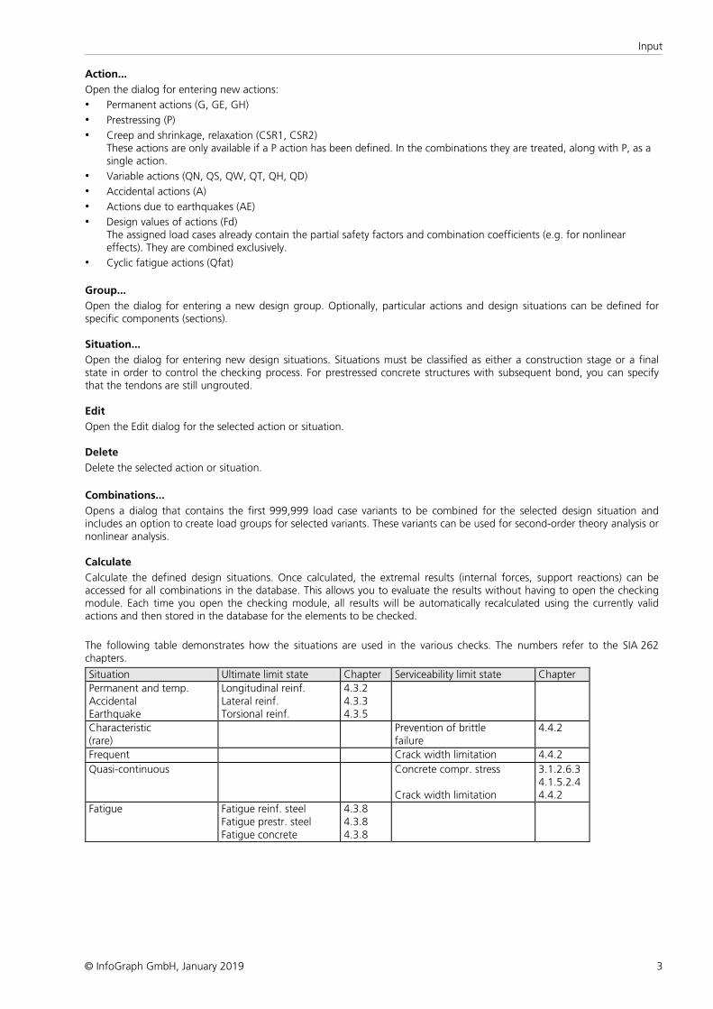
The following table demonstrates how the situations are used in the various checks. The numbers refer to the SIA 262chapters.
Situation Ultimate limit state Chapter Serviceability limit state Chapter Permanent and temp. Accidental Earthquake
Longitudinal reinf. Lateral reinf. Torsional reinf.
4.3.2 4.3.3 4.3.5
Characteristic (rare)
Prevention of brittle failure
4.4.2
Frequent Crack width limitation 4.4.2 Quasi-continuous Concrete compr. stress
Crack width limitation
3.1.2.6.3 4.1.5.2.4 4.4.2
Fatigue Fatigue reinf. steel Fatigue prestr. steel Fatigue concrete
4.3.8 4.3.8 4.3.8
4
SIA 262 Design
© InfoGraph GmbH, January 2019
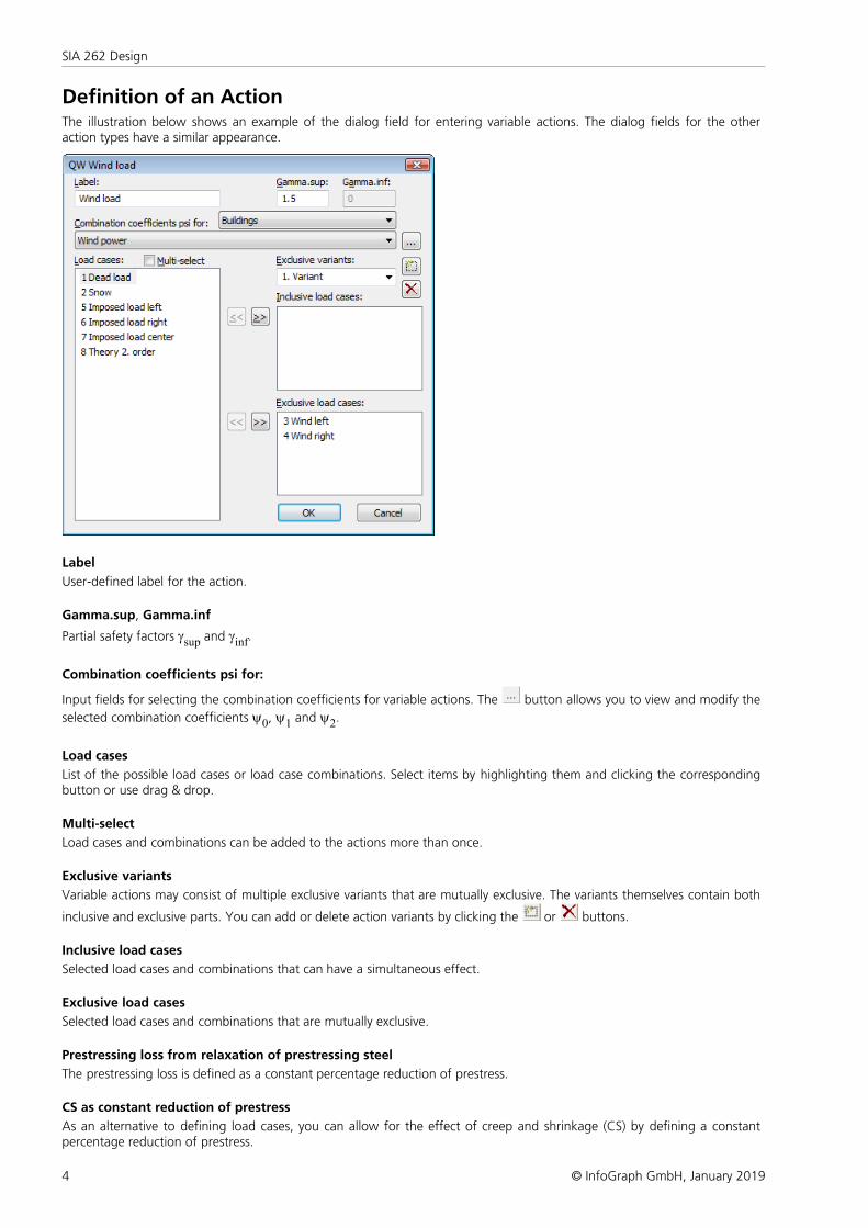
Definition of an ActionThe illustration below shows an example of the dialog field for entering variable actions. The dialog fields for the otheraction types have a similar appearance.
Label
User-defined label for the action.
Gamma.sup, Gamma.inf
Partial safety factors gsup and ginf.
Combination coefficients psi for:
Input fields for selecting the combination coefficients for variable actions. The button allows you to view and modify the
selected combination coefficients y0, y1 and y2.
Load cases
List of the possible load cases or load case combinations. Select items by highlighting them and clicking the correspondingbutton or use drag & drop.
Multi-select
Load cases and combinations can be added to the actions more than once.
Exclusive variants
Variable actions may consist of multiple exclusive variants that are mutually exclusive. The variants themselves contain both
inclusive and exclusive parts. You can add or delete action variants by clicking the or buttons.
Inclusive load cases
Selected load cases and combinations that can have a simultaneous effect.
Exclusive load cases
Selected load cases and combinations that are mutually exclusive.
Prestressing loss from relaxation of prestressing steel
The prestressing loss is defined as a constant percentage reduction of prestress.
CS as constant reduction of prestress
As an alternative to defining load cases, you can allow for the effect of creep and shrinkage (CS) by defining a constantpercentage reduction of prestress.
5
Input
© InfoGraph GmbH, January 2019
Internal prestressing
Selected load cases that describe internal prestressing. The reactions of the individual load cases are added up.
External prestressing
Selected load cases that describe external prestressing. The reactions of the individual load cases are added up.
Partial Safety FactorsThe partial safety factors for actions are determined by the definition of actions in accordance with SIA 260, Table 1, andcan be modified if necessary. The partial safety factors of the construction materials are preset with the values specified bySIA 262, Section 2.3.2.5.
Section InputThe section inputs contain all of the specific settings made for checks in the ultimate limit and serviceability states. Anoverview of the design specifications can be accessed in the SIA 262 Design section of the database.
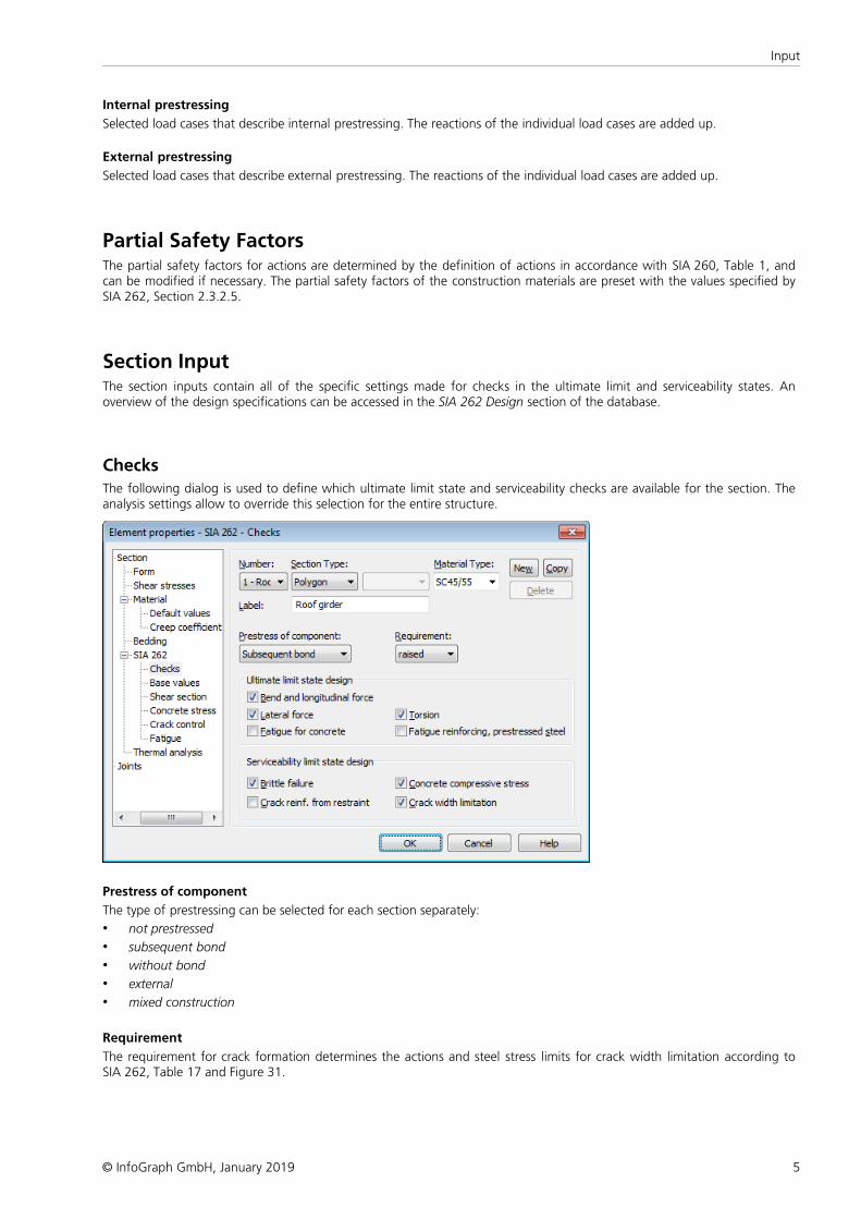
ChecksThe following dialog is used to define which ultimate limit state and serviceability checks are available for the section. Theanalysis settings allow to override this selection for the entire structure.
Prestress of component
The type of prestressing can be selected for each section separately:
• not prestressed
• subsequent bond
• without bond
• external
• mixed construction
Requirement
The requirement for crack formation determines the actions and steel stress limits for crack width limitation according toSIA 262, Table 17 and Figure 31.
6
SIA 262 Design
© InfoGraph GmbH, January 2019
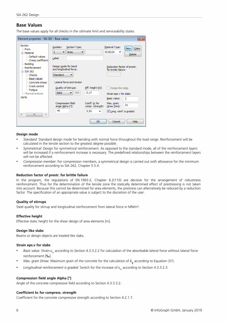
Base Values
The base values apply for all checks in the ultimate limit and serviceability states.
Design mode
• Standard: Standard design mode for bending with normal force throughout the load range. Reinforcement will becalculated in the tensile section to the greatest degree possible.
• Symmetrical: Design for symmetrical reinforcement. As opposed to the standard mode, all of the reinforcement layerswill be increased if a reinforcement increase is necessary. The predefined relationships between the reinforcement layerswill not be affected.
• Compression member: For compression members, a symmetrical design is carried out with allowance for the minimumreinforcement according to SIA 262, Chapter 5.5.4.
Reduction factor of prestr. for brittle failure
In the program, the regulations of EN 1992-2, Chapter 6.2(110) are decisive for the arrangement of robustnessreinforcement. Thus for the determination of the tensile zone the statically determined effect of prestressing is not takeninto account. Because this cannot be determined for area elements, the prestress can alternatively be reduced by a reductionfactor. The specification of an appropriate value is subject to the discretion of the user.
Quality of stirrups
Steel quality for stirrup and longitudinal reinforcement from lateral force in MN/m².
Effective height
Effective static height for the shear design of area elements [m].
Design like slabs
Beams or design objects are treated like slabs.
Strain eps.v for slabs
• Basic value: Strain ev according to Section 4.3.3.2.2 for calculation of the absorbable lateral force without lateral force
reinforcement [‰].
• Max. grain Dmax: Maximum grain of the concrete for the calculation of kg according to Equation (37).
• Longitudinal reinforcement is graded: Switch for the increase of ev according to Section 4.3.3.2.3.
Compression field angle Alpha [°]
Angle of the concrete compressive field according to Section 4.3.3.3.2.
Coefficient kc for compress. strength
Coefficient for the concrete compressive strength according to Section 4.2.1.7.
7
Input
© InfoGraph GmbH, January 2019
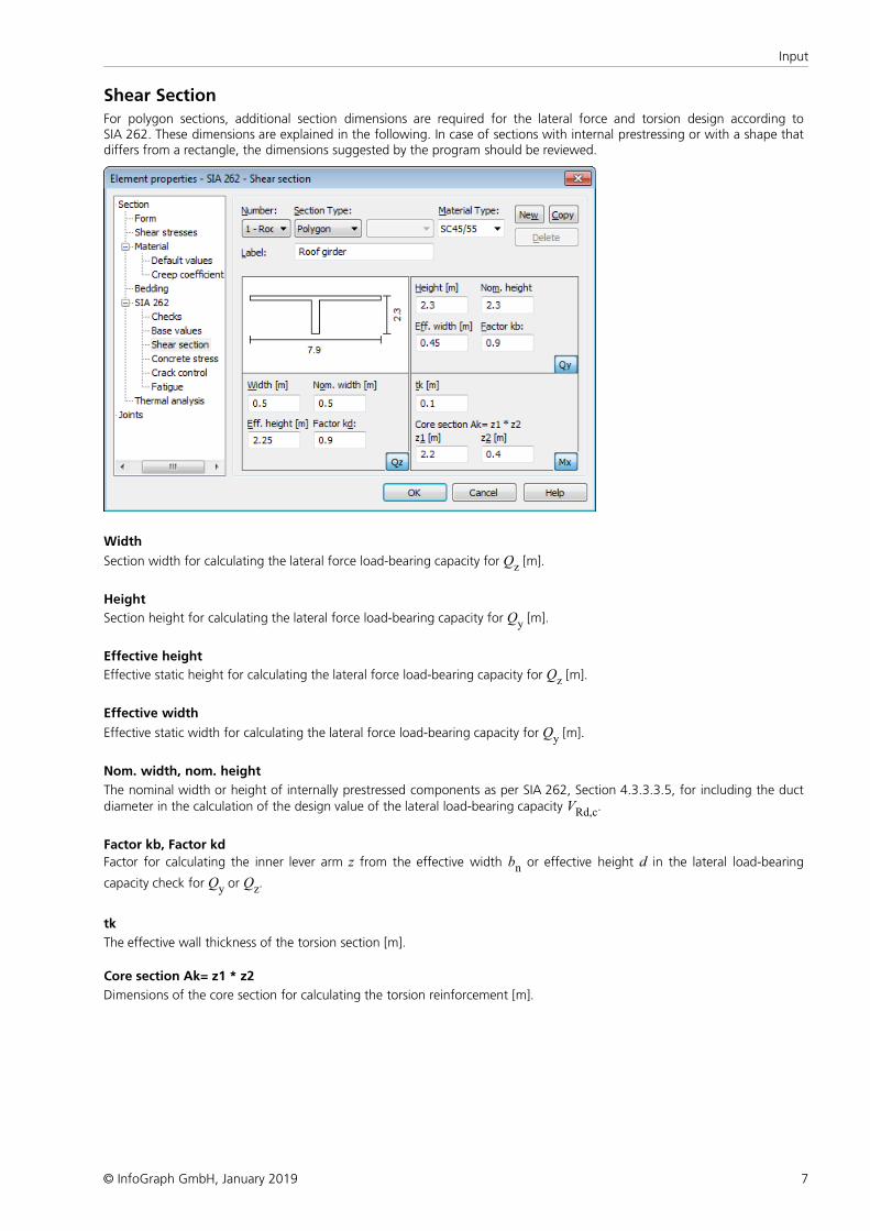
Shear Section
For polygon sections, additional section dimensions are required for the lateral force and torsion design according toSIA 262. These dimensions are explained in the following. In case of sections with internal prestressing or with a shape thatdiffers from a rectangle, the dimensions suggested by the program should be reviewed.
Width
Section width for calculating the lateral force load-bearing capacity for Qz [m].
Height
Section height for calculating the lateral force load-bearing capacity for Qy [m].
Effective height
Effective static height for calculating the lateral force load-bearing capacity for Qz [m].
Effective width
Effective static width for calculating the lateral force load-bearing capacity for Qy [m].
Nom. width, nom. height
The nominal width or height of internally prestressed components as per SIA 262, Section 4.3.3.3.5, for including the ductdiameter in the calculation of the design value of the lateral load-bearing capacity VRd,c.
Factor kb, Factor kd
Factor for calculating the inner lever arm z from the effective width bn or effective height d in the lateral load-bearing
capacity check for Qy or Qz.
tk
The effective wall thickness of the torsion section [m].
Core section Ak= z1 * z2
Dimensions of the core section for calculating the torsion reinforcement [m].
8
SIA 262 Design
© InfoGraph GmbH, January 2019
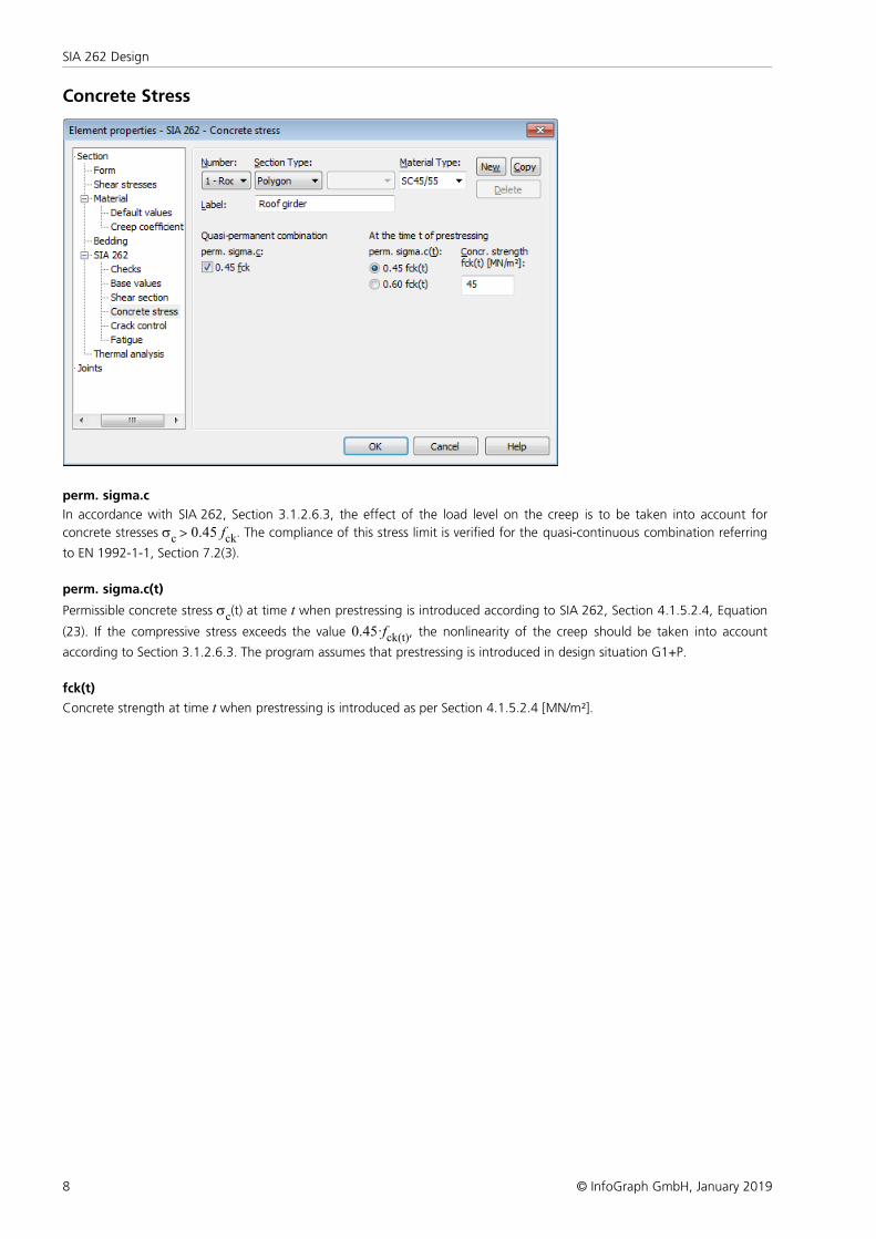
Concrete Stress
perm. sigma.c
In accordance with SIA 262, Section 3.1.2.6.3, the effect of the load level on the creep is to be taken into account for
concrete stresses sc > 0.45 fck. The compliance of this stress limit is verified for the quasi-continuous combination referring
to EN 1992-1-1, Section 7.2(3).
perm. sigma.c(t)
Permissible concrete stress sc(t) at time t when prestressing is introduced according to SIA 262, Section 4.1.5.2.4, Equation
(23). If the compressive stress exceeds the value 0.45·fck(t), the nonlinearity of the creep should be taken into account
according to Section 3.1.2.6.3. The program assumes that prestressing is introduced in design situation G1+P.
fck(t)
Concrete strength at time t when prestressing is introduced as per Section 4.1.5.2.4 [MN/m²].
9
Input
© InfoGraph GmbH, January 2019
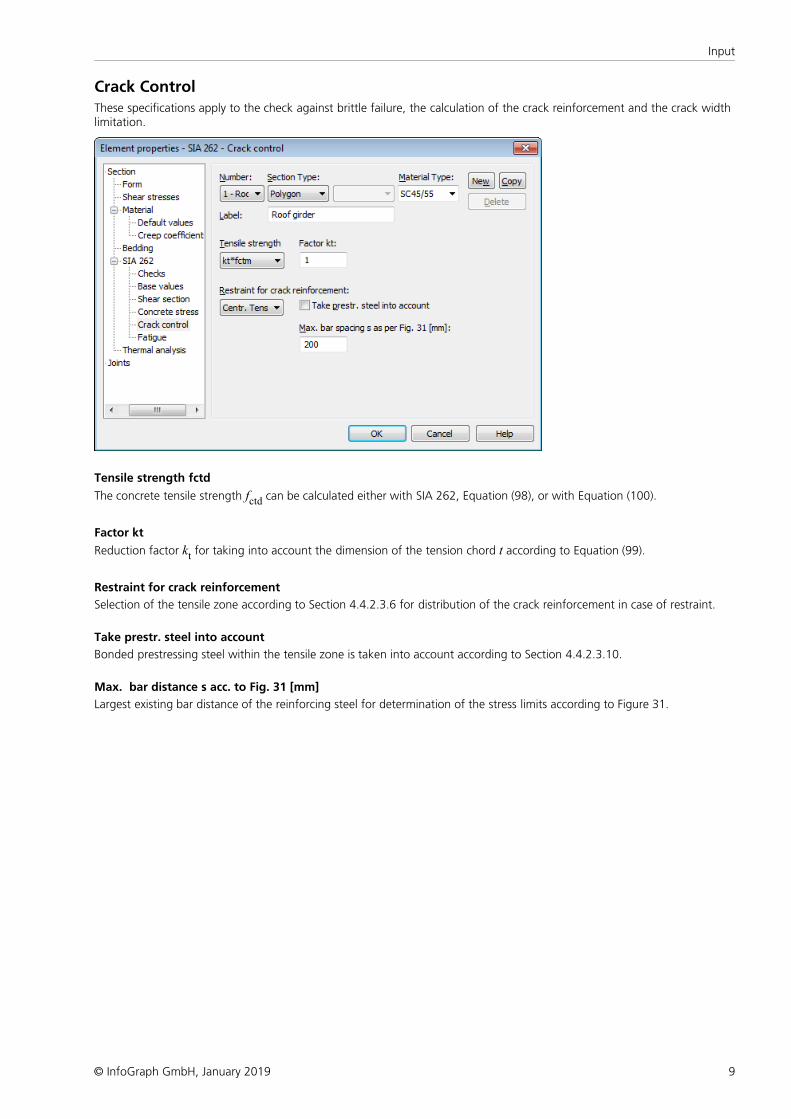
Crack Control
These specifications apply to the check against brittle failure, the calculation of the crack reinforcement and the crack widthlimitation.
Tensile strength fctd
The concrete tensile strength fctd can be calculated either with SIA 262, Equation (98), or with Equation (100).
Factor kt
Reduction factor kt for taking into account the dimension of the tension chord t according to Equation (99).
Restraint for crack reinforcement
Selection of the tensile zone according to Section 4.4.2.3.6 for distribution of the crack reinforcement in case of restraint.
Take prestr. steel into account
Bonded prestressing steel within the tensile zone is taken into account according to Section 4.4.2.3.10.
Max. bar distance s acc. to Fig. 31 [mm]
Largest existing bar distance of the reinforcing steel for determination of the stress limits according to Figure 31.
10
SIA 262 Design
© InfoGraph GmbH, January 2019
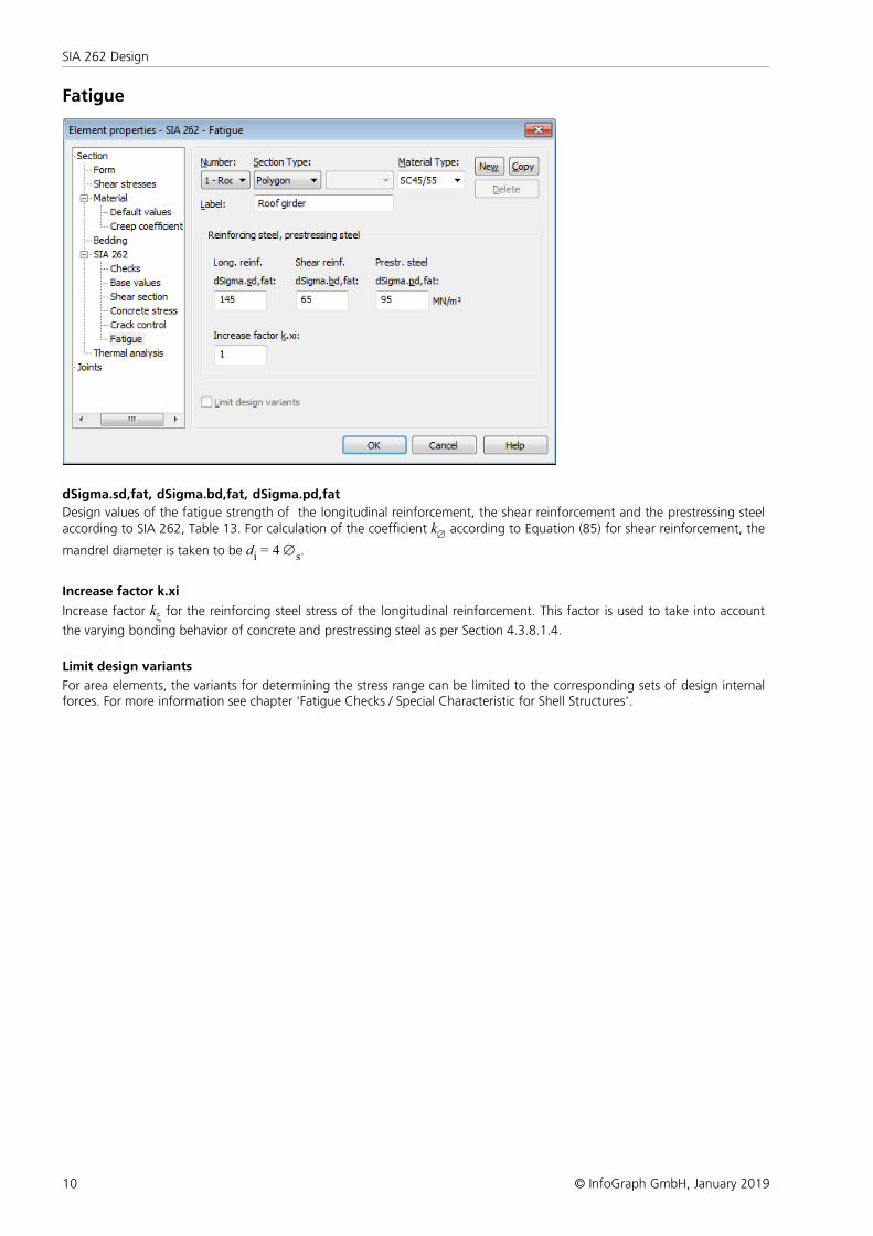
Fatigue
dSigma.sd,fat, dSigma.bd,fat, dSigma.pd,fat
Design values of the fatigue strength of the longitudinal reinforcement, the shear reinforcement and the prestressing steelaccording to SIA 262, Table 13. For calculation of the coefficient kÆ according to Equation (85) for shear reinforcement, the
mandrel diameter is taken to be di = 4 Æs.
Increase factor k.xi
Increase factor kx for the reinforcing steel stress of the longitudinal reinforcement. This factor is used to take into account
the varying bonding behavior of concrete and prestressing steel as per Section 4.3.8.1.4.
Limit design variants
For area elements, the variants for determining the stress range can be limited to the corresponding sets of design internalforces. For more information see chapter 'Fatigue Checks / Special Characteristic for Shell Structures'.
11
Input
© InfoGraph GmbH, January 2019
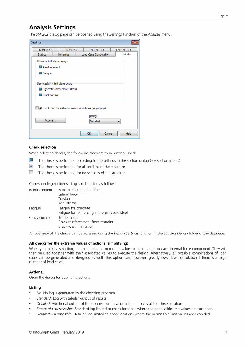
Analysis SettingsThe SIA 262 dialog page can be opened using the Settings function of the Analysis menu.
Check selection
When selecting checks, the following cases are to be distinguished:
The check is performed according to the settings in the section dialog (see section inputs).
The check is performed for all sections of the structure.
The check is performed for no sections of the structure.
Corresponding section settings are bundled as follows:
Reinforcement Bend and longitudinal forceLateral forceTorsionRobustness
Fatigue Fatigue for concreteFatigue for reinforcing and prestressed steel
Crack control Brittle failureCrack reinforcement from restraintCrack width limitation
An overview of the checks can be accessed using the Design Settings function in the SIA 262 Design folder of the database.
All checks for the extreme values of actions (simplifying)
When you make a selection, the minimum and maximum values are generated for each internal force component. They willthen be used together with their associated values to execute the design. Alternatively, all possible combinations of loadcases can be generated and designed as well. This option can, however, greatly slow down calculation if there is a largenumber of load cases.
Actions...
Open the dialog for describing actions.
Listing
• No: No log is generated by the checking program.
• Standard: Log with tabular output of results.
• Detailed: Additional output of the decisive combination internal forces at the check locations.
• Standard > permissible: Standard log limited to check locations where the permissible limit values are exceeded.
• Detailed > permissible: Detailed log limited to check locations where the permissible limit values are exceeded.
12
SIA 262 Design
© InfoGraph GmbH, January 2019
Single DesignThe single design function allows you to analyze individual section polygons separately from the whole system usingpredefined internal forces. The entry table can be found in the SIA 262 Design folder of the database.
Section
Number of the section to be designed.
Concrete
Concrete class SC12/15, ... SC50/60 or LSC12/13, ... LSC50/55
Apparent density
Apparent density of the lightweight concrete [kg/m³].
Combination
Design situation according to SIA 261, Section 4.4.3.4 or 4.4.3.5.
• 0: Permanent and temporary design situation.
• 1: Accidental design situation.
Nsd, Mysd, Mzsd
Internal forces that are designed.
Mode
• Standard: Standard design mode for bending with normal force throughout the load range. Reinforcement will becalculated in the tensile section to the greatest degree possible.
• Symmetrical: Design for symmetrical reinforcement. As opposed to the standard mode, all of the reinforcement layerswill be increased if a reinforcement increase is necessary. The predefined relationships between the reinforcement layerswill not be affected.
• Compression member: For compression members, a symmetrical design is carried out with allowance for the minimumreinforcement according to SIA 262, Section 5.5.4.
• Strains: Determine strain state for existing reinforcing steel layers.
• Inactive: Design disabled.
The calculation can be carried out while the input table is open using the Single Design or Page Preview menu item.
13
Input
© InfoGraph GmbH, January 2019
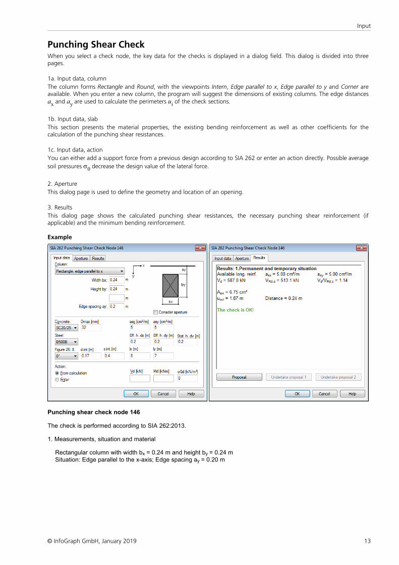
Punching Shear CheckWhen you select a check node, the key data for the checks is displayed in a dialog field. This dialog is divided into threepages.
1a. Input data, column
The column forms Rectangle and Round, with the viewpoints Intern, Edge parallel to x, Edge parallel to y and Corner areavailable. When you enter a new column, the program will suggest the dimensions of existing columns. The edge distancesax and ay are used to calculate the perimeters ui of the check sections.
1b. Input data, slab
This section presents the material properties, the existing bending reinforcement as well as other coefficients for thecalculation of the punching shear resistances.
1c. Input data, action
You can either add a support force from a previous design according to SIA 262 or enter an action directly. Possible average
soil pressures s0 decrease the design value of the lateral force.
2. Aperture
This dialog page is used to define the geometry and location of an opening.
3. Results
This dialog page shows the calculated punching shear resistances, the necessary punching shear reinforcement (ifapplicable) and the minimum bending reinforcement.
Example
Punching shear check node 146 The check is performed according to SIA 262:2013.
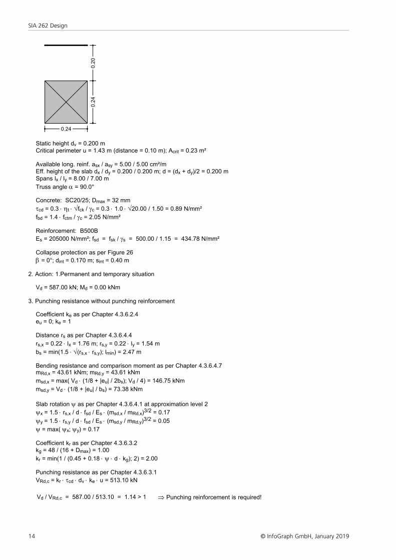
1. Measurements, situation and material
Rectangular column with width bx = 0.24 m and height by = 0.24 m Situation: Edge parallel to the x-axis; Edge spacing ay = 0.20 m
14
SIA 262 Design
© InfoGraph GmbH, January 2019
0.24
0.2
40.2
0
Static height dv = 0.200 m Critical perimeter u = 1.43 m (distance = 0.10 m); Acrit = 0.23 m² Available long. reinf. asx / asy = 5.00 / 5.00 cm²/m Eff. height of the slab dx / dy = 0.200 / 0.200 m; d = (dx + dy)/2 = 0.200 m Spans lx / ly = 8.00 / 7.00 m
Truss angle a = 90.0° Concrete: SC20/25; Dmax = 32 mm
tcd = 0.3 × ht × Öfck / gc = 0.3 × 1.0 × Ö20.00 / 1.50 = 0.89 N/mm²
fbd = 1.4 × fctm / gc = 2.05 N/mm² Reinforcement: B500B
Es = 205000 N/mm²; fsd = fsk / gs = 500.00 / 1.15 = 434.78 N/mm²
Collapse protection as per Figure 26
b = 0°; dint = 0.170 m; sint = 0.40 m
2. Action: 1.Permanent and temporary situation
Vd = 587.00 kN; Md = 0.00 kNm
3. Punching resistance without punching reinforcement
Coefficient ke as per Chapter 4.3.6.2.4 eu = 0; ke = 1
Distance rs as per Chapter 4.3.6.4.4
rs,x = 0.22 × lx = 1.76 m; rs,y = 0.22 × ly = 1.54 m
bs = min(1.5 × Ö(rs,x × rs,y); lmin) = 2.47 m
Bending resistance and comparison moment as per Chapter 4.3.6.4.7 mRd,x = 43.61 kNm; mRd,y = 43.61 kNm
msd,x = max( Vd × (1/8 + |eu| / 2bs); Vd / 4) = 146.75 kNm
msd,y = Vd × (1/8 + |eu| / bs) = 73.38 kNm
Slab rotation y as per Chapter 4.3.6.4.1 at approximation level 2
yx = 1.5 × rs,x / d × fsd / Es × (msd,x / mRd,x)3/2 = 0.17
yy = 1.5 × rs,y / d × fsd / Es × (msd,y / mRd,y)3/2 = 0.05
y = max( yx; yy) = 0.17
Coefficient kr as per Chapter 4.3.6.3.2 kg = 48 / (16 + Dmax) = 1.00
kr = min(1 / (0.45 + 0.18 × y × d × kg); 2) = 2.00
Punching resistance as per Chapter 4.3.6.3.1
VRd,c = kr × tcd × dv × ke × u = 513.10 kN
Vd / VRd,c = 587.00 / 513.10 = 1.14 > 1 Þ Punching reinforcement is required!
15
Input
© InfoGraph GmbH, January 2019
4. Punching reinforcement perpendicular to the slab plane
Design lateral force as per Chapter 4.3.6.5.2 Vd,s = max(Vd - VRd,c; Vd / 2) = 293.50 kN
Punching reinforcement as per Chapter 4.3.6.5.4
VRd,s = Asw × ke × ssd × sin 90°
Æsw = 16 mm as per Table 20
ssd = min(Es × y / 6 × (1 + fbd / fsd × d / Æsw); fsd) = 434.78 N/mm²
Asw = Vd,s / ke / ssd = 6.75 cm²
Reinforcement arrangement as per Chapter 5.5.3.8, Figure 39 and Table 20 - The punching reinforcement should consist of two or more rows - The first row should have a minimal distance of 0.07 m from the edge of the supported area - The radial distance of the reinforcing rows must not exceed 0.07 m - The outmost row should have a distance of 0.14 m from the edge of the supported area - In the second row, the tangential distance of the reinforcing elements must not exceed 0.30 m
Check of the concret compressive strut at the supported area as per Chapter 4.3.6.5.7
VRd,c = min( 2 × kr; 3.5) × tcd × dv × ke × u = 897.93 kN
Vd / VRd,c = 587.00 / 897.93 = 0.65 £ 1 Þ Check is OK!
Punching shear check outside of the reinforced zone as per Chapter 4.3.6.5.9 and Figure 25 Check perimeter uout = 1.87 m; Distance = 0.24 m The static height is assumed to be dv = 0.20 m
VRd,c,out = kr × tcd × dv × ke × uout = 670.46 kN
Vd / VRd,c,out = 587.00 / 670.46 = 0.88 £ 1 Þ Check is OK!
5. Collaps protection
Check section as per Figure 26: uint = sint + p / 2 × dint = 0.67 m
kb = 0.37 as per Table 12 for ductility class B Residual resistance at check section as per Chapter 4.3.6.7.2
VRd,res = As × fsd × kb £ 1.7 × tcd × dint × uint
As = min( Vd; 1.7 × tcd × dint × uint) / (fsd × kb) = 10.72 cm²
16
SIA 262 Design
© InfoGraph GmbH, January 2019
Prestressed Structures
Internal PrestressingFor internal prestressing, the tendon groups as well as the prestressing system and procedures are entered using thePrestressing function of the Structure menu. To include them in the FEM calculation, you then need to define a load case ofthe Prestressing load type. For more information, refer to the Prestressed Concrete section of the manual.
Prestressing with bond and prestressing without bond are differentiated in the section inputs and the specifications for theCreep and shrinkage load case.
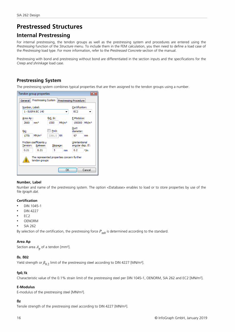
Prestressing System
The prestressing system combines typical properties that are then assigned to the tendon groups using a number.
Number, Label
Number and name of the prestressing system. The option <Database> enables to load or to store properties by use of thefile Igraph.dat.
Certification
• DIN 1045-1
• DIN 4227
• EC2
• OENORM
• SIA 262
By selection of the certification, the prestressing force Pm0 is determined according to the standard.
Area Ap
Section area Ap of a tendon [mm²].
ßs, ß02
Yield strength or ß0.2 limit of the prestressing steel according to DIN 4227 [MN/m²].
fp0,1k
Characteristic value of the 0.1% strain limit of the prestressing steel per DIN 1045-1, OENORM, SIA 262 and EC2 [MN/m²].
E-Modulus
E-modulus of the prestressing steel [MN/m²].
ßz
Tensile strength of the prestressing steel according to DIN 4227 [MN/m²].
17
Prestressed Structures
© InfoGraph GmbH, January 2019
fpk
Characteristic value of the tensile strength of the prestressing steel per DIN 1045-1, OENORM, SIA 262 and EC2 [MN/m²].
Pm0
The permissible prestressing force of a tendon [kN] that corresponds to the selected certification is displayed where theminimum of the two possible values is decisive. After releasing the input field, a different prestressing force can be defined.
Certification as per DIN 1045-1:
Pm0 = Ap · 0.85 fp0,1k or Ap · 0.75 fpk according to DIN 1045-1, Eq. (49).
Certification as per DIN 4227:
Pm0 = Ap · 0.75 ßs or Ap · 0.55 ßz according to DIN 4227, Tab. 9, Row 65.
Certification as per EC2:
Pm0 = Ap · 0.85 fp0,1k or Ap · 0.75 fpk according to EN 1992-1-1, Eq. (5.43).
Certification as per OENORM:
Pm0 = Ap · 0.80 fp0,1k or Ap · 0.70 fpk according to OENORM B 4750, Eq. (4) and (5), and OENORM B 1992-1-1,
Chapter 8.9.6.
Certification as per SIA 262:
Pm0 = Ap · 0.7 fpk according to SIA 262, Eq. (22), Chapter 4.1.5.2.2.
Duct diameter
Is used for the decompression check according to the European standard and for beam tendons to calculate the net sectionvalues [mm].
Friction coefficients
Friction coefficients m for prestressing and release.
Slippage
Slippage at the prestressing anchor [mm].
Unintentional deviation angle ß'
Unintentional deviation angle of a tendon [°/m].
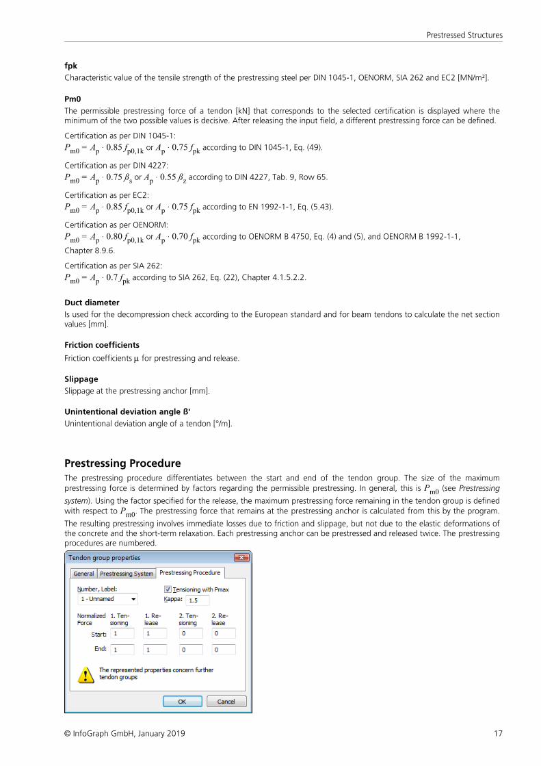
Prestressing Procedure
The prestressing procedure differentiates between the start and end of the tendon group. The size of the maximumprestressing force is determined by factors regarding the permissible prestressing. In general, this is Pm0 (see Prestressing
system). Using the factor specified for the release, the maximum prestressing force remaining in the tendon group is definedwith respect to Pm0. The prestressing force that remains at the prestressing anchor is calculated from this by the program.
The resulting prestressing involves immediate losses due to friction and slippage, but not due to the elastic deformations ofthe concrete and the short-term relaxation. Each prestressing anchor can be prestressed and released twice. The prestressingprocedures are numbered.
18
SIA 262 Design
© InfoGraph GmbH, January 2019
Number, Label
Number and name of the prestressing procedure.
Tensioning with Pmax
Selecting this check box causes the factors for tensioning correspond to the maximum force Pmax for tendons certified
according to DIN 1045-1 or EC2 (see the following example).
Kappa
If tensioning with Pmax is selected, the permissible maximum force is calculated using the allowance value k to ensure there
is an overstressing reserve.
1. Tensioning
Factor relating to Pm0 or Pmax for the prestressing force at the tie at the 1st instance of tensioning.
1. Release
Factor relating to Pm0 for the maximum remaining prestressing force at the 1st release. '0': no release!
2. Tensioning
Factor relating to Pm0 or Pmax for the prestressing force at the tie for the 2nd tensioning. '0': no 2nd tensioning!
2. Release
Factor relating to Pm0 for the maximum remaining prestressing force at the 2nd release. '0': no 2nd release!
The prestressing force curve is determined in the following sequence:
- Tensioning and release at the start,
- Tensioning and release at the end,
- Slippage at the start,
- Slippage at the end.
The differences between tensioning with Pm0 and Pmax are described in the following examples.
The user is responsible for checking the permissibility of the maximum force during the stressing process.
Examples for Prestressing Procedures
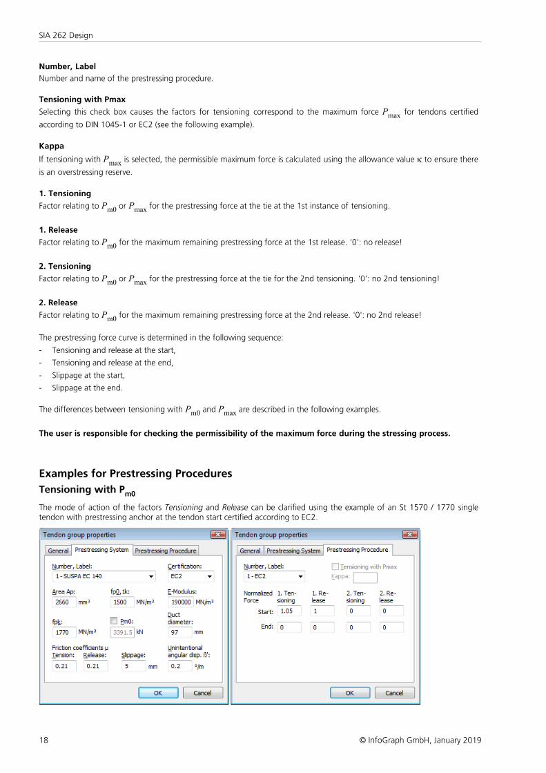
Tensioning with Pm0
The mode of action of the factors Tensioning and Release can be clarified using the example of an St 1570 / 1770 singletendon with prestressing anchor at the tendon start certified according to EC2.
19
Prestressed Structures
© InfoGraph GmbH, January 2019
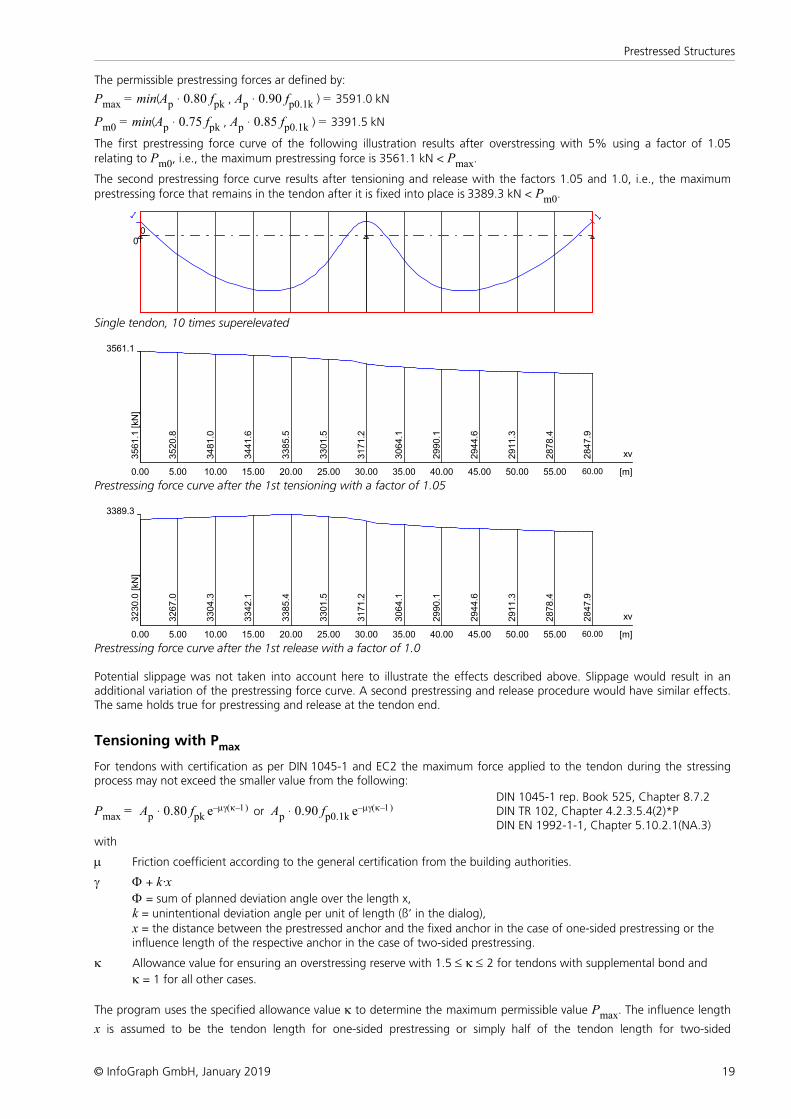
The permissible prestressing forces ar defined by:
Pmax = min(Ap · 0.80 fpk , Ap · 0.90 fp0.1k ) = 3591.0 kN
Pm0 = min(Ap · 0.75 fpk , Ap · 0.85 fp0.1k ) = 3391.5 kN
The first prestressing force curve of the following illustration results after overstressing with 5% using a factor of 1.05relating to Pm0, i.e., the maximum prestressing force is 3561.1 kN < Pmax.
The second prestressing force curve results after tensioning and release with the factors 1.05 and 1.0, i.e., the maximumprestressing force that remains in the tendon after it is fixed into place is 3389.3 kN < Pm0.
00
Single tendon, 10 times superelevated
3561.1
xv
[m]0.00
3561.1
[kN
]
5.00
3520.8
10.00
3481.0
15.00
3441.6
20.00
3385.5
25.00
3301.5
30.00
3171.2
35.00
3064.1
40.00
2990.1
45.002944.6
50.00
2911.3
55.00
2878.4
60.00
2847.9
Prestressing force curve after the 1st tensioning with a factor of 1.05
3389.3
xv
[m]0.00
3230.0
[kN
]
5.00
3267.0
10.00
3304.3
15.00
3342.1
20.00
3385.4
25.00
3301.5
30.00
3171.2
35.00
3064.1
40.00
2990.1
45.00
2944.6
50.00
2911.3
55.00
2878.4
60.00
2847.9
Prestressing force curve after the 1st release with a factor of 1.0
Potential slippage was not taken into account here to illustrate the effects described above. Slippage would result in anadditional variation of the prestressing force curve. A second prestressing and release procedure would have similar effects.The same holds true for prestressing and release at the tendon end.
Tensioning with Pmax
For tendons with certification as per DIN 1045-1 and EC2 the maximum force applied to the tendon during the stressingprocess may not exceed the smaller value from the following:
Pmax = Ap · 0.80 fpk e-mg(k-1) or Ap · 0.90 fp0.1k
e-mg(k-1)DIN 1045-1 rep. Book 525, Chapter 8.7.2DIN TR 102, Chapter 4.2.3.5.4(2)*PDIN EN 1992-1-1, Chapter 5.10.2.1(NA.3)
with
m Friction coefficient according to the general certification from the building authorities.
g F + k·xF = sum of planned deviation angle over the length x,k = unintentional deviation angle per unit of length (ß’ in the dialog),
x = the distance between the prestressed anchor and the fixed anchor in the case of one-sided prestressing or theinfluence length of the respective anchor in the case of two-sided prestressing.
k Allowance value for ensuring an overstressing reserve with 1.5 £ k £ 2 for tendons with supplemental bond and
k = 1 for all other cases.
The program uses the specified allowance value k to determine the maximum permissible value Pmax. The influence length
x is assumed to be the tendon length for one-sided prestressing or simply half of the tendon length for two-sided
20
SIA 262 Design
© InfoGraph GmbH, January 2019
prestressing.
In this setting the overstressing factor refers to Pmax, which means the value 1.0 is used to select the maximum
force permitted by the standard.
The release factor continues to refer to Pm0. Setting the value to 1.0 also assures that the force remaining in the tendon
after it fixed into place is within the permissible range.
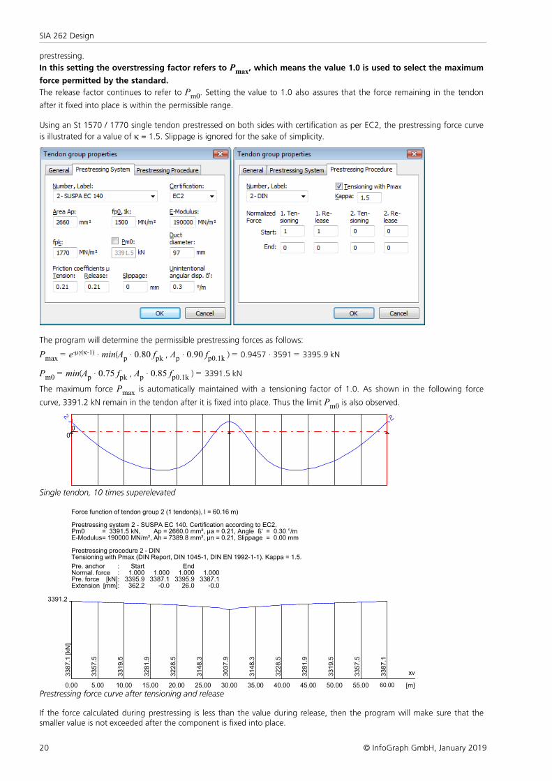
Using an St 1570 / 1770 single tendon prestressed on both sides with certification as per EC2, the prestressing force curve
is illustrated for a value of k = 1.5. Slippage is ignored for the sake of simplicity.
The program will determine the permissible prestressing forces as follows:
Pmax = e-mg(k-1) · min(Ap · 0.80 fpk , Ap · 0.90 fp0.1k ) = 0.9457 · 3591 = 3395.9 kN
Pm0 = min(Ap · 0.75 fpk , Ap · 0.85 fp0.1k ) = 3391.5 kN
The maximum force Pmax is automatically maintained with a tensioning factor of 1.0. As shown in the following force
curve, 3391.2 kN remain in the tendon after it is fixed into place. Thus the limit Pm0 is also observed.
00
Single tendon, 10 times superelevated
Force function of tendon group 2 (1 tendon(s), l = 60.16 m)
Prestressing system 2 - SUSPA EC 140. Certification according to EC2.Pm0 = 3391.5 kN, Ap = 2660.0 mm², µa = 0.21, Angle ß' = 0.30 °/mE-Modulus= 190000 MN/m², Ah = 7389.8 mm², µn = 0.21, Slippage = 0.00 mm
Prestressing procedure 2 - DINTensioning with Pmax (DIN Report, DIN 1045-1, DIN EN 1992-1-1). Kappa = 1.5.
Pre. anchor : Start EndNormal. force : 1.000 1.000 1.000 1.000Pre. force [kN]: 3395.9 3387.1 3395.9 3387.1Extension [mm]: 362.2 -0.0 26.0 -0.0
3391.2
xv
[m]0.00
3387.1
[kN
]
5.00
3357.5
10.00
3319.5
15.00
3281.9
20.00
3228.5
25.00
3148.3
30.00
3037.9
35.00
3148.3
40.00
3228.5
45.00
3281.9
50.00
3319.5
55.00
3357.5
60.00
3387.1
Prestressing force curve after tensioning and release
If the force calculated during prestressing is less than the value during release, then the program will make sure that thesmaller value is not exceeded after the component is fixed into place.
21
Prestressed Structures
© InfoGraph GmbH, January 2019
External Prestressing, Mixed ConstructionExternal prestressing can be taken into account by entering the external forces directly in the program. For mixedconstruction, the additional tendons with bond must be entered as described above.
Creep and ShrinkageSimilar to prestressing, creep and shrinkage are taken into account by specifying a corresponding load case (Creep andshrinkage load type) in the FEM calculation. Besides the creep-generating permanent load case, you also need to specifywhether the internal forces relocation between concrete and prestressing steel is to be taken into account. This option isonly useful in the case of tendons with bond.
The decisive creep and shrinkage coefficients for calculating the Creep and shrinkage load case are entered in the sectiondialog.
The program determines concrete creep and shrinkage based on a time-dependent stress-strain law developed by Trost.
( )Sb,b,0bb
b )(1
)( e-e×j-ej×r+
=s tE
t
In this case:
sb(t) Concrete stress from creep and shrinkage at time t.
Eb E-modulus of the concrete.
r Relaxation coefficient according to Trost for time t (normally r = 0.80).
j Creep coefficient for time t.
eb(t) Concrete strain from creep and shrinkage at time t.
eb,0 Concrete strain from creep-generating continuous load.
eb,s Concrete strain from shrinkage.
Under consideration of these relationships, a time-dependent global stiffness matrix and the associated load vectors areconstructed which, in turn, yield the internal forces and deformations of the concrete. The resulting stress changes in theprestressing steel are also determined provided they are selected in the load case. Any influence from the relaxation of theprestressing steel will be ignored in this case. According to Zilch/Rogge (2002, p. 256), this influence can be calculatedseparately (see following section) and combined with the changes from creep and shrinkage for all time-dependentprestressing losses:
Dsp,csr = Dspr + Ep · Decpt
with
Dspr Prestressing loss from relaxation of the prestressing steel.
Decpt Concrete strain change from creep and shrinkage.
Ep E-modulus of the prestressing steel.
Relaxation of Prestressing SteelAccording to SIA 262, Section 3.3.2.7.1, the design values of the stress loss from relaxation of the prestressing steel for aduration of 1000 h can be taken from Figure 8. Long time values of the stress loss can be determined by multiplying thesevalues with the factor 3.
You can define the stress losses in the CSR actions of the SIA 262 Actions dialog.
22
SIA 262 Design
© InfoGraph GmbH, January 2019
Checks in the Ultimate Limit StatesThe following checks are available:
• Bending and bending with normal force (SIA 262, Chapter 4.3.2)
• Lateral force (Chapter 4.3.3)
• Torsion and combined load (Chapter 4.3.5)
• Punching shear (Chapter 4.3.6).
• Fatigue (Chapter 4.3.8)
The following combinations in accordance with SIA 260, Chapter 4.4.3, are taken into account in the ultimate limit states:
• Permanent and temporary design situations
},,,{ k,i0,ik,1Q,1kPkGd QQPGEE ×y×g×g×g= (16)
• Accidental design situations
},,,{ k,i2,idkkd QAPGEE ×y= (17)
• Design situations resulting from earthquakes (AE) according to SIA 261, Section 16.1.4.
},,,{ k,i2,iEkkd QAPGEE ×y=
• Fatigue combination according to SIA 262, Chapter 4.3.8, combined with EN 1992-1-1, Chapter 6.8.3, Equation(6.68).
{ }fatk,i2,ik,11,1kkd };,,,{ QQQPGEE ×y×y= (6.68)
In this equation Qk,1 and Qk,i are non-cyclic, non-permanent actions, whereas Qfat defines the action of the relevant
fatigue load.
For each combination you can define different design situations for the construction stages and final states. Whenconducting the check, the extreme value deriving from all combinations and situations is decisive.
Stress-Strain-CurvesThe following characteristics are used for section design:
• Concrete: parabola-rectangle diagram according to SIA 262, Figure 12 and Equation (28). The coefficient ht in
Equations (2) and (3) which considers the effect of load duration on concrete strength, is assumed to be ht = 1
according to Section 4.2.1.3.
• Reinforcing steel: stress-strain curve according to Figure 16, with rising upper branch and ks = 1.05.
• Prestressing steel: stress-strain curve according to Figure 17, with horizontal upper branch according to Section 4.2.3.5.
The check against fatigue is carried out in the cracked state with a linear stress-strain curve according to Section 4.3.8.1.3.
Design Internal ForcesThe design internal forces are derived from the action combinations and are separate for the variants defined in theconstruction stages and final states.
With area elements, the design internal forces correspond to the plasticity approach from Wolfensberger and Thürlimann.This approach takes into account how much the reinforcement deviates from the crack direction. Due to the current lack ofprecise data regarding the combined load of reinforced concrete shell structures from bending and normal force, the designinternal forces for bending and normal force are calculated independently according to the static limit theorem of theplasticity theory and then used together as the basis for the design. This approach should always lead to results that are onthe safe side.
For 3D stressed beams and design objects, the shear design is performed separately for the Qy and Qz lateral forces. The
simultaneous effect of shear and torsion stress is taken into account in accordance with Chapter 4.3.5.
Depending on the section type and reinforcement configuration, the variants of design internal forces listed below are takeninto account.
23
Checks in the Ultimate Limit States
© InfoGraph GmbH, January 2019
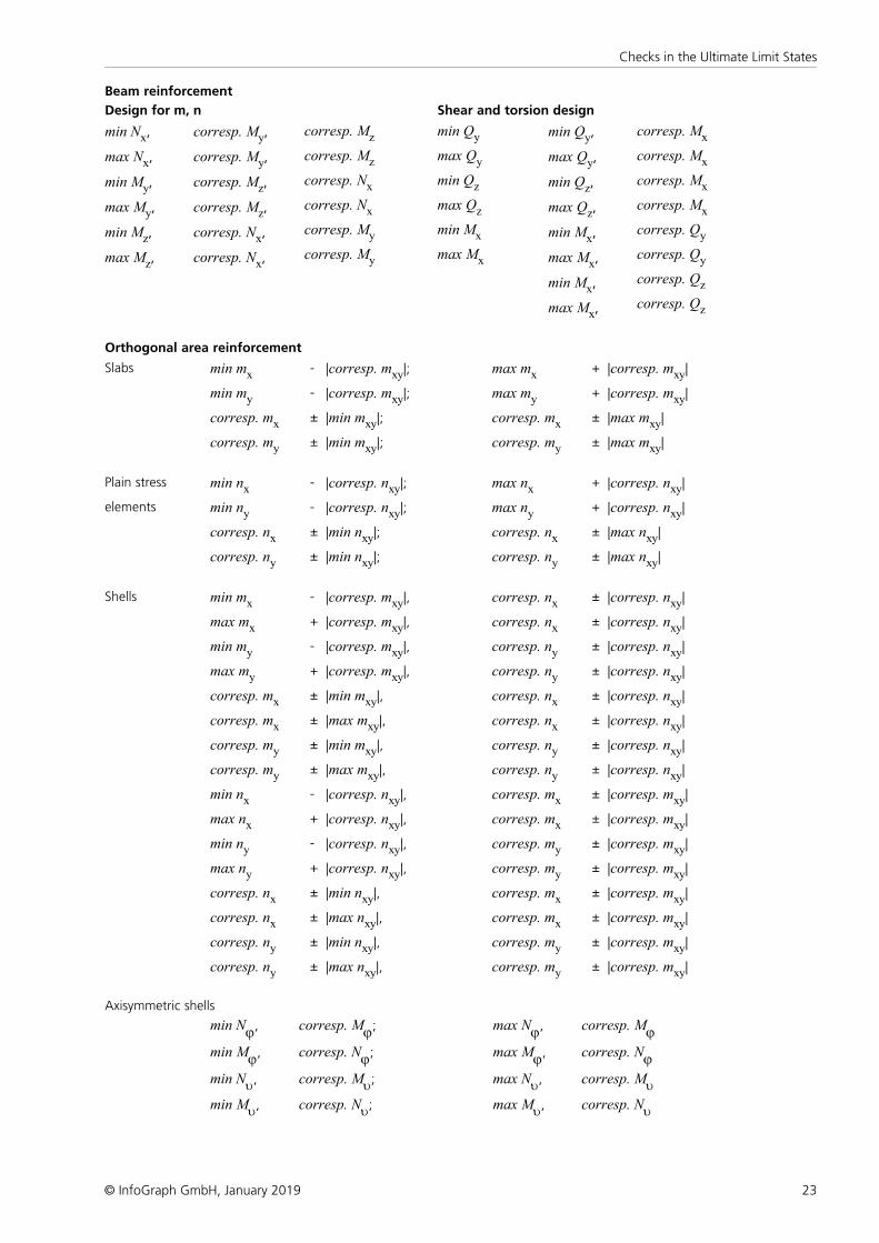
Beam reinforcement
Design for m, n Shear and torsion design
min Nx,
max Nx,
min My,
max My,
min Mz,
max Mz,
corresp. My,
corresp. My,
corresp. Mz,
corresp. Mz,
corresp. Nx,
corresp. Nx,
corresp. Mz
corresp. Mz
corresp. Nx
corresp. Nx
corresp. My
corresp. My
min Qy
max Qy
min Qz
max Qz
min Mx
max Mx
min Qy,
max Qy,
min Qz,
max Qz,
min Mx,
max Mx,
min Mx,
max Mx,
corresp. Mx
corresp. Mx
corresp. Mx
corresp. Mx
corresp. Qy
corresp. Qy
corresp. Qz
corresp. Qz
Orthogonal area reinforcement
Slabs min mx- |corresp. mxy|; max mx
+ |corresp. mxy|
min my- |corresp. mxy|; max my
+ |corresp. mxy|
corresp. mx± |min mxy|; corresp. mx
± |max mxy|
corresp. my± |min mxy|; corresp. my
± |max mxy|
Plain stress min nx- |corresp. nxy|; max nx
+ |corresp. nxy|
elements min ny- |corresp. nxy|; max ny
+ |corresp. nxy|
corresp. nx± |min nxy|; corresp. nx
± |max nxy|
corresp. ny± |min nxy|; corresp. ny
± |max nxy|
Shells min mx- |corresp. mxy|, corresp. nx
± |corresp. nxy|
max mx+ |corresp. mxy|, corresp. nx
± |corresp. nxy|
min my- |corresp. mxy|, corresp. ny
± |corresp. nxy|
max my+ |corresp. mxy|, corresp. ny
± |corresp. nxy|
corresp. mx± |min mxy|, corresp. nx
± |corresp. nxy|
corresp. mx± |max mxy|, corresp. nx
± |corresp. nxy|
corresp. my± |min mxy|, corresp. ny
± |corresp. nxy|
corresp. my± |max mxy|, corresp. ny
± |corresp. nxy|
min nx- |corresp. nxy|, corresp. mx
± |corresp. mxy|
max nx+ |corresp. nxy|, corresp. mx
± |corresp. mxy|
min ny- |corresp. nxy|, corresp. my
± |corresp. mxy|
max ny+ |corresp. nxy|, corresp. my
± |corresp. mxy|
corresp. nx± |min nxy|, corresp. mx
± |corresp. mxy|
corresp. nx± |max nxy|, corresp. mx
± |corresp. mxy|
corresp. ny± |min nxy|, corresp. my
± |corresp. mxy|
corresp. ny± |max nxy|, corresp. my
± |corresp. mxy|
Axisymmetric shells
min Nj,
min Mj,
min Nu,
min Mu,
corresp. Mj;
corresp. Nj;
corresp. Mu;
corresp. Nu;
max Nj,
max Mj,
max Nu,
max Mu,
corresp. Mj
corresp. Nj
corresp. Mu
corresp. Nu
24
SIA 262 Design
© InfoGraph GmbH, January 2019
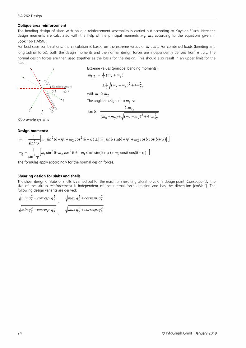
Oblique area reinforcement
The bending design of slabs with oblique reinforcement assemblies is carried out according to Kuyt or Rüsch. Here thedesign moments are calculated with the help of the principal moments m1, m2 according to the equations given in
Book 166 DAfStB.
For load case combinations, the calculation is based on the extreme values of m1, m2. For combined loads (bending and
longitudinal force), both the design moments and the normal design forces are independently derived from n1, n2. The
normal design forces are then used together as the basis for the design. This should also result in an upper limit for theload.
Coordinate systems
Extreme values (principal bending moments):
)( yx21
1,2 mmm +×=
2xy
2yx2
1 4)( mmm +-±
with m1 ³ m2
The angle d assigned to m1 is:
2xy
2yxyx
xy
4)()(
2tan
mmmmm
m
×+-+-
×=d
Design moments:
[ ])(coscos)(sinsin)(cos)(sinsin
121
22
212
y+dd+y+dd±y+d+y+dy
=h mmmmm
[ ])(coscos)(sinsincossinsin
121
22
212
y+dd+y+dd±d+dy
=x mmmmm
The formulas apply accordingly for the normal design forces.
Shearing design for slabs and shells
The shear design of slabs or shells is carried out for the maximum resulting lateral force of a design point. Consequently, thesize of the stirrup reinforcement is independent of the internal force direction and has the dimension [cm²/m²]. Thefollowing design variants are derived:
2y
2x . qcorrespqmin +
,
2y
2x . qcorrespqmax +
2x
2y . qcorrespqmin +
,
2x
2y . qcorrespqmax +
25
Checks in the Ultimate Limit States
© InfoGraph GmbH, January 2019
Design for Bending and Bending with Normal ForceThe design for bending and bending with normal force is carried out using a detailed section analysis according to SIA 262,Section 4.3.2.3, where the coefficient for the concrete compressive strength kc = 1.0 is assumed. As a simplification,
calculations are performed with ks = 1.05 and eud = 0.020 for all reinforcing steel types. The design includes slab, plain
stress and shell elements with perpendicular or inclined reinforcement as well as beams. For each internal forcecombination, the necessary reinforcement due to the equilibrium conditions of the reinforced concrete section isdetermined iteratively. The final result is derived from the extreme value of all calculated reinforcements.
You can control the result of the design by specifying the reinforcement geometry and choosing one of three designmodes:
Mode Standard
This is the standard design mode for bending with longitudinal force throughout the entire load area. Reinforcement will be
calculated in the tensile section to the greatest degree possible. For reasons of economy, if the steel strain esd part of the
steel strength fsd is exceeded, compressive reinforcement is determined. The requirements for the minimum reinforcement
for the less stressed direction of slabs and walls according to Section 5.5.3.2 resp. 5.5.4.11 are not taken into accountduring bending design.
Mode Symmetrical
In contrast to the standard design, the reinforcement will be applied at all predefined locations in all strain areas, ifnecessary. The specified relationships between the reinforcement layers will not be affected.
Mode Compression member
The design is performed symmetrically. Additionally, the minimum reinforcement of 0.6% required according toSection 5.5.4.2 of the standard is determined. This calculation is based on the entire area of the concrete section.
Design for Lateral ForceThe design for lateral force includes the determination of lateral force reinforcement and the check of the resistance of theconcrete compressive field according to SIA 262, Chapter 4.3.3. The following special conditions apply:
• The angle of the diagonal tensile reinforcement is assumed to be 90°.
• The minimum reinforcement according to Section 5.5.2.2 of the standard is included in the calculated stirrupreinforcement.
• Slab and shell elements are designed for the lateral force qr = Ö(qx² + qy²).
• There is no limitation on the check locations according to Section 4.3.3.2.1 or 4.3.3.4.1 as well as no reduction of theaction from loads near supports according to Section 4.3.3.2.7.
• For beams and design objects, the decisive values of the equivalent rectangle are determined by the user independentlyof the normal section geometry. The coefficients for calculating the inner lever arm z based on the effective width andeffective height according to Section 4.3.3.4.2 must also be specified.
• For area elements, the calculation is normally performed with the lever arm z = 0.9 d.
• The coefficient kc for the concrete compressive strength defined by the user is taken into account.
Formulas used from the standard:
4.3.3.2 Components without Lateral Force Reinforcement
4.3.3.2.1 Lateral force resistance of slabs without lateral force reinforcement
vRd = kd tcd dv (35)
gkdk
vd
1
1
e+= (36)
max16
48
Dkg
+= (37)
Dmax Maximum grain in the concrete. Dmax= 0 for lightweight concrete.
tcd Design value of the shear stress limit.
c
ckcd
3.0
g
h=t
ft(3)
26
SIA 262 Design
© InfoGraph GmbH, January 2019
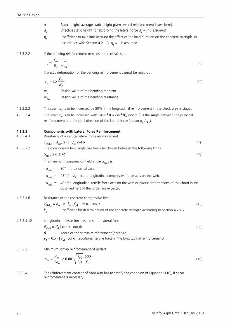
d Static height, average static height given several reinforcement layers [mm].
dv Effective static height for absorbing the lateral force dv = d is assumed.
ht Coefficient to take into account the effect of the load duration on the concrete strength. In
accordance with Section 4.2.1.3, ht = 1 is assumed.
4.3.3.2.2 If the bending reinforcement remains in the elastic state:
Rd
d
s
sdv
m
m
E
f=e (38)
If plastic deformation of the bending reinforcement cannot be ruled out:
s
sdv
E
f5.1=e (39)
md Design value of the bending moment.
mRd Design value of the bending resistance.
4.3.3.2.3 The strain ev is to be increased by 50% if the longitudinal reinforcement in the check area is staged.
4.3.3.2.4 The strain ev is to be increased with 1/(sin4 J + cos4 J), where J is the Angle between the principal
reinforcement and principal direction of the lateral force (arctan qy / qx).
4.3.3.3 Components with Lateral Force Reinforcement
4.3.3.4.3 Resistance of a vertical lateral force reinforcement
VRd,s = Asw /s · z · fsd cot a (43)
4.3.3.3.2 The compression field angle can freely be chosen between the following limits:
amin £ a £ 45° (40)
The minimum compression field angle amin is:
- amin = 30° in the normal case,
- amin = 25° if a significant longitudinal compressive force acts on the web,
- amin = 40° if a longitudinal tensile force acts on the web or plastic deformations of the chord in the
observed part of the girder are expected.
4.3.3.4.6 Resistance of the concrete compressive field
VRd,c = bw · z · kc · fcd · sin a · cos a (45)
kc Coefficient for determination of the concrete strength according to Section 4.2.1.7.
4.3.3.4.12 Longitudinal tensile force as a result of lateral force
FtVd = Vd ( cot a - cot ß) (50)
ß Angle of the stirrup reinforcement (here 90°).
Ft = 0.5 · | Vd | cot a (additional tensile force in the longitudinal reinforcement)
5.5.2.2 Minimum stirrup reinforcement of girders
sk
ck
w
sww
f
f
bs
A 500
30001.0³=r (110)
5.5.3.4 The reinforcement content of slabs also has to satisfy the condition of Equation (110), if shearreinforcement is necessary.
27
Checks in the Ultimate Limit States
© InfoGraph GmbH, January 2019
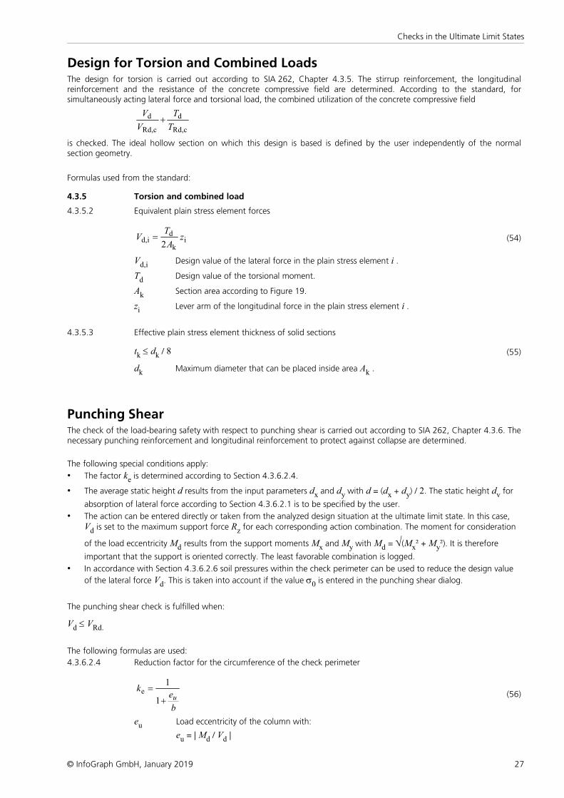
Design for Torsion and Combined LoadsThe design for torsion is carried out according to SIA 262, Chapter 4.3.5. The stirrup reinforcement, the longitudinalreinforcement and the resistance of the concrete compressive field are determined. According to the standard, forsimultaneously acting lateral force and torsional load, the combined utilization of the concrete compressive field
cRd,
d
cRd,
d
T
T
V
V+
is checked. The ideal hollow section on which this design is based is defined by the user independently of the normalsection geometry.
Formulas used from the standard:
4.3.5 Torsion and combined load
4.3.5.2 Equivalent plain stress element forces
ik
dd,i
2z
A
TV = (54)
Vd,i Design value of the lateral force in the plain stress element i .
Td Design value of the torsional moment.
Ak Section area according to Figure 19.
zi Lever arm of the longitudinal force in the plain stress element i .
4.3.5.3 Effective plain stress element thickness of solid sections
tk £ dk / 8 (55)
dk Maximum diameter that can be placed inside area Ak .
Punching ShearThe check of the load-bearing safety with respect to punching shear is carried out according to SIA 262, Chapter 4.3.6. Thenecessary punching reinforcement and longitudinal reinforcement to protect against collapse are determined.
The following special conditions apply:
• The factor ke is determined according to Section 4.3.6.2.4.
• The average static height d results from the input parameters dx and dy with d = (dx + dy) / 2. The static height dv for
absorption of lateral force according to Section 4.3.6.2.1 is to be specified by the user.
• The action can be entered directly or taken from the analyzed design situation at the ultimate limit state. In this case, Vd is set to the maximum support force Rz for each corresponding action combination. The moment for consideration
of the load eccentricity Md results from the support moments Mx and My with Md = Ö(Mx² + My²). It is therefore
important that the support is oriented correctly. The least favorable combination is logged.
• In accordance with Section 4.3.6.2.6 soil pressures within the check perimeter can be used to reduce the design value
of the lateral force Vd. This is taken into account if the value s0 is entered in the punching shear dialog.
The punching shear check is fulfilled when:
Vd £ VRd.
The following formulas are used:
4.3.6.2.4 Reduction factor for the circumference of the check perimeter
b
ek
u+
=
1
1e (56)
eu Load eccentricity of the column with:
eu = | Md / Vd |
28
SIA 262 Design
© InfoGraph GmbH, January 2019
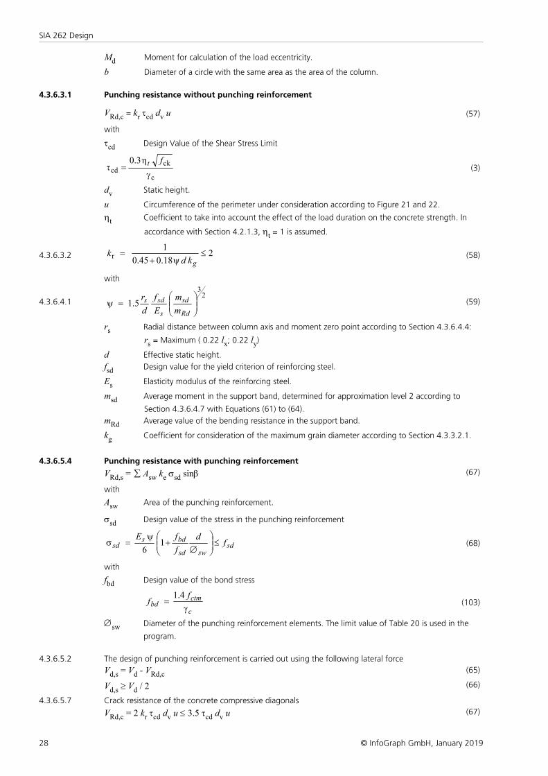
Md Moment for calculation of the load eccentricity.
b Diameter of a circle with the same area as the area of the column.
4.3.6.3.1 Punching resistance without punching reinforcement
VRd,c = kr tcd dv u (57)
with
tcd Design Value of the Shear Stress Limit
c
ckcd
3.0
g
h=t
ft(3)
dv Static height.
u Circumference of the perimeter under consideration according to Figure 21 and 22.
ht Coefficient to take into account the effect of the load duration on the concrete strength. In
accordance with Section 4.2.1.3, ht = 1 is assumed.
4.3.6.3.2
218.045.0
1r £
y+=
gkd k (58)
with
4.3.6.4.1
23
5.1 ÷÷ø
öççè
æ=y
Rd
sd
s
sds
m
m
E
f
d
r (59)
rs Radial distance between column axis and moment zero point according to Section 4.3.6.4.4:
rs = Maximum ( 0.22 lx; 0.22 ly)
d Effective static height.
fsd Design value for the yield criterion of reinforcing steel.
Es Elasticity modulus of the reinforcing steel.
msd Average moment in the support band, determined for approximation level 2 according to
Section 4.3.6.4.7 with Equations (61) to (64).
mRd Average value of the bending resistance in the support band.
kg Coefficient for consideration of the maximum grain diameter according to Section 4.3.3.2.1.
4.3.6.5.4 Punching resistance with punching reinforcement
VRd,s = å Asw ke ssd sinb (67)
with
Asw Area of the punching reinforcement.
ssd Design value of the stress in the punching reinforcement
sdswsd
bdssd f
d
f
fE £÷
÷ø
öççè
æ
Æ+
y=s 1
6(68)
with
fbd Design value of the bond stress
c
ctmbd
f f
g=
4.1(103)
Æsw Diameter of the punching reinforcement elements. The limit value of Table 20 is used in the
program.
4.3.6.5.2 The design of punching reinforcement is carried out using the following lateral force
Vd,s = Vd - VRd,c(65)
Vd,s ³ Vd / 2 (66)
4.3.6.5.7 Crack resistance of the concrete compressive diagonals
VRd,c = 2 kr tcd dv u £ 3.5 tcd dv u (67)
29
Checks in the Ultimate Limit States
© InfoGraph GmbH, January 2019
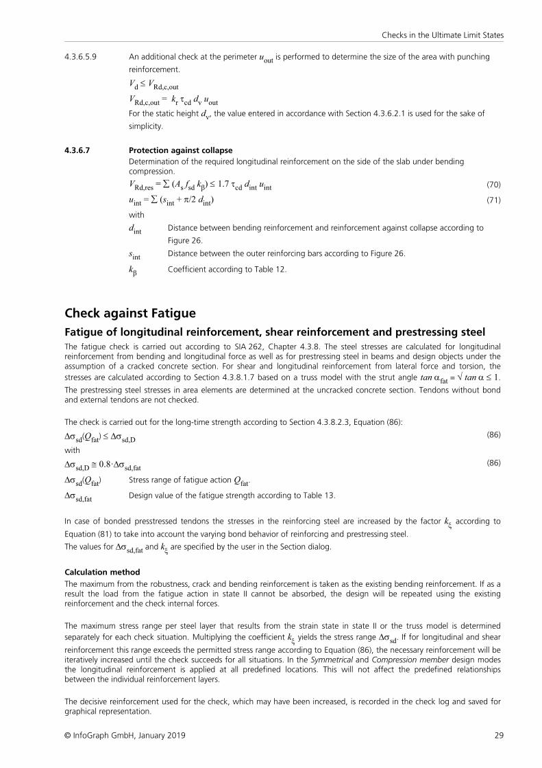
4.3.6.5.9 An additional check at the perimeter uout is performed to determine the size of the area with punching
reinforcement.
Vd £ VRd,c,out
VRd,c,out = kr tcd dv uout
For the static height dv, the value entered in accordance with Section 4.3.6.2.1 is used for the sake of
simplicity.
4.3.6.7 Protection against collapse
Determination of the required longitudinal reinforcement on the side of the slab under bendingcompression.
VRd,res = å (As fsd kβ) £ 1.7 tcd dint uint (70)
uint = å (sint + p/2 dint) (71)
with
dint Distance between bending reinforcement and reinforcement against collapse according to
Figure 26.
sint Distance between the outer reinforcing bars according to Figure 26.
kβ Coefficient according to Table 12.
Check against Fatigue
Fatigue of longitudinal reinforcement, shear reinforcement and prestressing steelThe fatigue check is carried out according to SIA 262, Chapter 4.3.8. The steel stresses are calculated for longitudinalreinforcement from bending and longitudinal force as well as for prestressing steel in beams and design objects under theassumption of a cracked concrete section. For shear and longitudinal reinforcement from lateral force and torsion, the
stresses are calculated according to Section 4.3.8.1.7 based on a truss model with the strut angle tan afat = Ö tan a £ 1.
The prestressing steel stresses in area elements are determined at the uncracked concrete section. Tendons without bondand external tendons are not checked.
The check is carried out for the long-time strength according to Section 4.3.8.2.3, Equation (86):
Dssd(Qfat) £ Dssd,D(86)
with
Dssd,D @ 0.8·Dssd,fat(86)
Dssd(Qfat) Stress range of fatigue action Qfat.
Dssd,fat Design value of the fatigue strength according to Table 13.
In case of bonded presstressed tendons the stresses in the reinforcing steel are increased by the factor kx according to
Equation (81) to take into account the varying bond behavior of reinforcing and prestressing steel.
The values for Dssd,fat and kx are specified by the user in the Section dialog.
Calculation method
The maximum from the robustness, crack and bending reinforcement is taken as the existing bending reinforcement. If as aresult the load from the fatigue action in state II cannot be absorbed, the design will be repeated using the existingreinforcement and the check internal forces.
The maximum stress range per steel layer that results from the strain state in state II or the truss model is determined
separately for each check situation. Multiplying the coefficient kx yields the stress range Dssd. If for longitudinal and shear
reinforcement this range exceeds the permitted stress range according to Equation (86), the necessary reinforcement will beiteratively increased until the check succeeds for all situations. In the Symmetrical and Compression member design modesthe longitudinal reinforcement is applied at all predefined locations. This will not affect the predefined relationshipsbetween the individual reinforcement layers.
The decisive reinforcement used for the check, which may have been increased, is recorded in the check log and saved forgraphical representation.
30
SIA 262 Design
© InfoGraph GmbH, January 2019
Fatigue of concrete under compressive stress
The fatigue check for concrete that is subject to compressive stress is performed for bending and longitudinal force at thecracked section. This check takes into account the final longitudinal reinforcement and may include an increase appliedduring the fatigue check for reinforcing steel. The struts of components subject to lateral force stress are not analyzed.
The check according to Section 4.3.8.3.1 is proved, if Equation (91) is fulfilled:
|scd|max £ 0.5 kc fcd + 0.45 |scd|min £ 0.9 kc fcd (91)
with
|scd|max, |scd|min Design values of the maximum and minimum concrete compressive stress for the fatigue action Qfat.
In the case of tensile stresses, |scd|min is assumed to be zero.
kc The reduction coefficient for the concrete compressive strength is assumed to be kc = 1.0 according
to Section 4.2.1.7.
Special characteristic of shell structuresIn shell structures the strain state at the cracked concrete section under general stress cannot be determinedunambiguously. The design is therefore carried out separately for the reinforcement directions x and y with the designinternal forces from Wolfensberger/Thürlimann or Rüsch as described above. The reinforcement calculated in this manneryields a reliable load-bearing capacity.
When calculating the stress range for reinforcing steel and concrete, this method can lead to unrealistic results in the caseof torsional or shear stresses as shown in the following example:
Assume two identical sets of slab internal forces:
Set mx [kNm/m] my [kNm/m] mxy [kNm/m] 1 300 200 100 2 300 200 100
According to Wolfensberger/Thürlimann, this results in design variants for the x direction:
Set Variant m [kNm/m] 1 1 mx + |mxy| = 400 2 mx - |mxy| = 200 2 1 mx + |mxy| = 400 2 mx - |mxy| = 200
The torsional moments generate a variation of the design moments and thus a calculatory stress range. This may lead to anecessary reinforcement increase in the fatigue check due to apparent overstressing. For normal design forces, this appliescorrespondingly to the shear forces.
Selecting Limit design variants in the Section dialog allows you to avoid the described effect. In this case only thecorresponding variants are compared when determining the stress range, i.e. only the first and second variants of both setsin this example. Assuming constant stress, the stress range is thus correctly determined to be zero.
This alternative, however, does not ensure that all conceivable stress fluctuations are analyzed. You shouldtherefore be particularly careful when assessing the results. For this purpose the detailed log indicates the mainvariants and design internal forces used for the check.
When determining the design internal forces according to Rüsch for inclined reinforcement, the described relationshipsapply accordingly.
31
Checks in the Serviceability Limit States
© InfoGraph GmbH, January 2019
Checks in the Serviceability Limit StatesThe following checks are performed:
• Limiting the concrete compressive stresses (SIA 262, Section 3.1.2.6.3 and 4.1.5.2.4).
• Minimum reinforcement against brittle failure (robustness reinforcement)(Chapter 4.4.2).
• Crack reinforcement in case of restraint (Chapter 4.4.2).
• Crack width limitation (Chapter 4.4.2).
In accordance with SIA 260, Section 4.4.4.4, the following combinations are taken into account in the serviceability limitstates:
• Rare situations
},,,{ k,i0,ik,1kkd QQPGEE ×y= (20)
• Frequent situations
},,,{ k,i2,ik,11,1kkd QQPGEE ×y×y= (21)
• Quasi-continuous situations
},,{ k,i2,ikkd QPGEE ×y= (22)
Limiting the Concrete Compressive Stresses
The concrete compressive stress check is carried out in state I. For area elements the concrete stresses are calculated at thegross section. For beams and design objects, the bending stress is calculated
- without internal tendons at the gross section,
- with internal tendons without bond at the net section,
- with internal tendons with bond for situations before being grouted at the net section or otherwise at the ideal section.
In accordance with SIA 262, Section 3.1.2.6.3, the influence of the load level on the creep behavior is to be taken into
account for concrete stresses sc > 0.45 fck. If selected in the section dialog, this stress limit is verified for the quasi-
continuous combination based on EN 1992-1-1, Section 7.2(3).
In prestressed concrete components the concrete compressive stresses during and after the prestressing process may notexceed the value 0.6 fck(t) at any location of the structure out of the anchoring area according to SIA 262, Section 4.1.5.2.4.
If the concrete compressive stress also exceeds the value 0.45 fck(t), the nonlinearity of the creep must be taken into
account. fck(t) indicates the characteristic value of the concrete compressive strength at time t when the prestressing is
introduced.
The program assumes the time of introducing the prestressing to coincide with situation G1+P. If a quasi-continuoussituation G1+P is defined, the concrete stress is checked against the limit value 0.45 fck(t) or 0.6 fck(t) for this situation
depending on the user's specification. The value for fck(t) is also defined in the dialog.
Minimum Reinforcement against Brittle FailureAccording to SIA 262, Chapter 4.4.2, brittle failure of concrete in the tensile zone must be prevented by installation of aminimum reinforcement. The minimum reinforcement (Robustness reinforcement) is calculated for the crack moment usingthe design values of the tensile strength fctd and the steel strength fsd:
As = Mcr / ( fsd · z )
with
Mcr Crack moment by which a tensile stress of fctd occurs without prestressing effect at the section edge.
z Lever arm of internal forces.
The crack moment results in Mcr = Wc · fctd, the lever arm z of the internal forces is assumed to be 0.9 · d for the sake of
simplicity. In accordance with Section 4.4.2.3.6 the minimum reinforcement is to be placed in the tensile zone of thecomponents. Referring to EN 1992-2, Section 6.1(110), the rare action combination is used to determine the tensile zone. In
32
SIA 262 Design
© InfoGraph GmbH, January 2019
this process the statically undetermined prestressing effect should be taken into account rather than the staticallydetermined prestressing effect. The program determines all stresses at the gross section. The statically determinedprestressing effect can only be subtracted for beams and design objects. For area elements the prestress is alternativelyreduced by a user-defined reduction factor.
The calculated reinforcement is evenly distributed to the reinforcement layers in the tensile zone. In the design modesymmetrical reinforcement is also applied to the remaining layers. This will not affect the predefined relationships betweenthe individual reinforcement layers. For sections with mode compression member the robustness reinforcement is notchecked because minimum reinforcement is already determined during the design for bending with longitudinal force.
Crack Reinforcement in Case of RestraintThe installation of a minimum reinforcement can be used to limit the crack width in case of imposed or obstructeddeformations according to SIA 262, Section 4.4.2.3.7. In accordance with Section 4.4.2.3.6 the minimum reinforcement isto be placed in the tensile zone of the components. The tensile zone is defined by the user in the section dialog by selectionof a restraint action (tension at the top/bottom, centrical tension).
The minimum reinforcement is calculated with the following equation:
As = ks · fctd ·Act / ss,adm
with
ks Coefficient for consideration of stress distribution prior to crack formation:
ks = 1.0 for centrical restraint
ks = 0.4 for bending restraint of rectangular sections, deduced from
SIA D 0182, Eq. (10.7)
ks = 0.9 · Fcr / Act / fctd ³ 0.5 in all other cases according to EN 1992-1-1, Eq. (7.3)
with the tensile force Fcr in the tension chord in state I directly before crack formation with the edge stress fctd.
The tensile force is calculated by integrating the tensile stresses over the area Act.
fctd Design value of the concrete tensile strength. Depending on the selection in the section dialog one of the
following equations is used:
fctd = kt · fctm (98)
fctd = kt · fctk0.95 (100)
with
tkt
5.01
1
+= (99)
t Smallest dimension of the observed tension chord [m]. For slabs and rectangular sections under bending
load, t = h/3 applies.
The coefficient kt can be defined in the section dialog. The suggested value is kt = 1.0.
Act Area of the concrete tensile zone at initial crack formation in state I.
ss,adm Reinforcing steel strength according to Figure 31, depending on the selected requirement (Table 17) and the bar
distance of the longitudinal reinforcement.
If selected by the user, bonded prestressing steel within the tensile zone can optionally be taken into account for As
according to Section 4.4.2.3.10.
33
Checks in the Serviceability Limit States
© InfoGraph GmbH, January 2019
Crack Width LimitationLimitation of crack width is performed by comparing the existing reinforcing steel stresses with the permitted steel stressesaccording to SIA 262, Table 17 and Figure 31. The reinforcing steel stresses are calculated in state II for the maximum ofrobustness, crack and bending reinforcement including a possible increase resulting from the fatigue check. Depending onthe selected requirement, the reinforcing steel stresses may not exceed the following values:
Action combination Requirement
frequent quasi-continuous
raised fsd - 80 N/mm² -
high fsd - 80 N/mm² ss,adm from Figure 31, curve C
If the check cannot be proved with the existing reinforcement, the crack reinforcement will be increased.
Limiting DeformationsAccording to SIA 262, Chapter 4.4.3, the deformations of a component or structure may not impair its proper functioningor appearance. Considering that, the deformation should not exceed the limits specified in SIA 260.
The InfoCAD program system allows you to perform a realistic check as part of a nonlinear system analysis for beam andshell structures that takes geometric and physical nonlinearities into account. The resistance of the tendons with bond iscurrently not included in the calculation.
Editing is performed in the following steps:
• Define the check situation with the Load group function in the Load dialog through grouping the decisive individualload cases. The variable loads must first be weighted with the combination coefficients of the combination specified inSIA 260.
• Select the check load cases in the Nonlinear Analysis / Serviceability dialog of the analysis settings for the FEM orframework analysis.
• Set the reinforcement determined in the ultimate limit state in the Start reinforcement selection field (maximum frombending, robustness, crack check and fatigue).
• Perform the FEM or framework analysis to determine the deformations in state II.
• Check the system deformations displayed graphically or in tabular form.
For a detailed description of the nonlinear system analysis, refer to the relevant chapter of the manual.
ResultsThe extremal values for internal forces, support reactions, deformations, soil pressures and stresses are saved for all checksituations. The resulting bending, minimum- and crack reinforcement, the decisive maximum value and the stirrup andtorsion reinforcement are provided for the graphical representation as well.
The log shows the design internal forces and necessary reinforcements, checked stresses or crack widths at each resultlocation. If the permissible limit values are exceeded, they are reported as warnings and indicated at the check location. Thedetailed log also lists the decisive combination internal forces of all design situations.
Stresses for beams and design objects
sx Longitudinal stress in the concrete compressive stress check [MN/m²].
ss, Dss Stresses and stress ranges for reinforcing steel [MN/m²].
sp, Dsp Stresses and stress ranges for prestressing steel [MN/m²].
scd, Dscd Stresses and stress ranges in the fatigue check for concrete under longitudinal compression [MN/m²].
Dssb,y, Dssb,z Stress ranges for shear reinforcement from Qy and Qz [MN/m²].
Dssb,T, Dssl,T Stress ranges for shear reinforcement from torsion and for longitudinal torsion reinforcement [MN/m²].
s / sperm Stress utilization.
Ds / Dsperm Stress range utilization.
34
SIA 262 Design
© InfoGraph GmbH, January 2019
Stresses for area elements
sx, sy Longitudinal stress in x or y direction [MN/m²].
ssx, Dssx Stresses and stress ranges for reinforcing steel in the x direction [MN/m²].
ssy, Dssy Stresses and stress ranges for reinforcing steel in the y direction [MN/m²].
sp, Dsp Stresses and stress ranges for prestressing steel [MN/m²].
scd,x, Dscd,x, Stresses and stress ranges in the concrete fatigue check under longitudinal compression in the x-
scd,y, Dscd,y and y-direction [MN/m²].
Dss,b Stress ranges for shear reinforcement [MN/m²].
s / sperm Stress utilization.
Ds / Dsperm Stress range utilization.
Bending Reinforcement
As Bending reinforcement [cm²] for beams.
asx, asy Bending reinforcement [cm²/m] for area elements in the x and y direction.
asj Meridian reinforcement [cm²/m] for axisymmetric shell elements.
asu Ring reinforcement [cm²/m] for axisymmetric shell elements.
Reinforcement from lateral force
asb Stirrup reinforcement [cm²/m²] of area and axisymmetric shell elements.
Asb.y Stirrup reinforcement of beams from Qy [cm²/m].
Asb.z Stirrup reinforcement of beams from Qz [cm²/m].
asq Longitudinal reinforcement from the lateral force design of area elements [cm²/m].
Asl.y Longitudinal reinforcement of beams from Qy [cm²].
Asl.z Longitudinal reinforcement of beams from Qz [cm²].
Torsion reinforcement
Asb Stirrup reinforcement of beams from torsion [cm²/m].
Asl,T Longitudinal reinforcement of beams from torsion [cm²].
Design values
VyRdc Resistance of the concrete compressive field with respect to Qy [kN].
VzRdc Resistance of the concrete compressive field with respect to Qz [kN].
Q/VRdc+ Mx/TRdc Utilization of the concrete compressive field as a result of combined load from lateral force and torsion.
TRdc Resistance of the concrete compressive field with respect to Mx [kNm].
35
Examples
© InfoGraph GmbH, January 2019
Examples
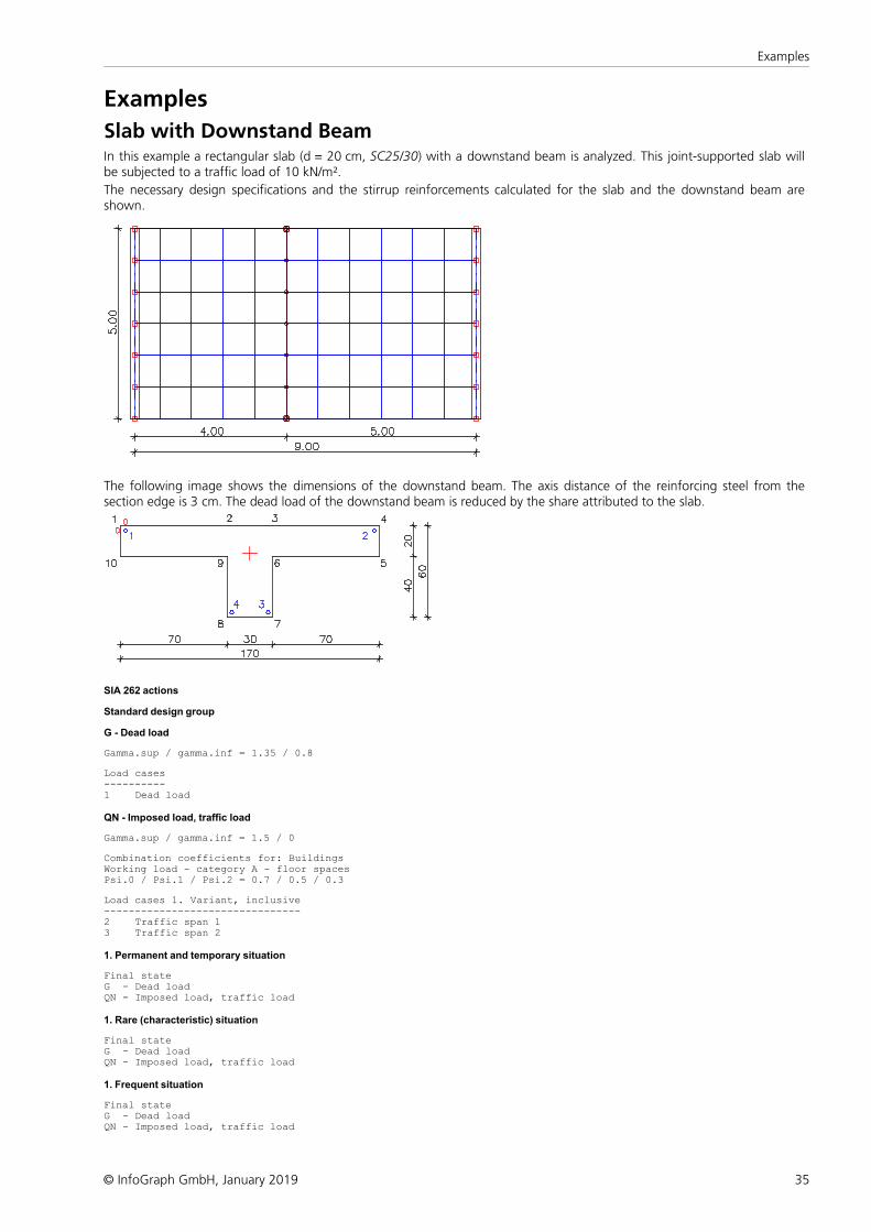
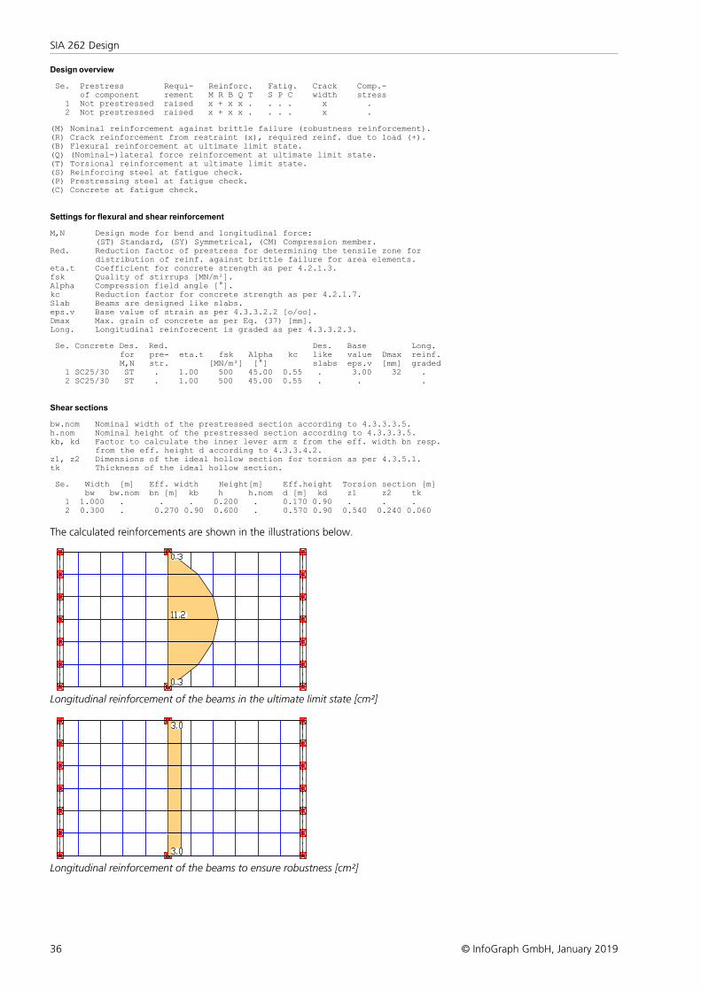
Slab with Downstand BeamIn this example a rectangular slab (d = 20 cm, SC25/30) with a downstand beam is analyzed. This joint-supported slab willbe subjected to a traffic load of 10 kN/m².
The necessary design specifications and the stirrup reinforcements calculated for the slab and the downstand beam areshown.
The following image shows the dimensions of the downstand beam. The axis distance of the reinforcing steel from thesection edge is 3 cm. The dead load of the downstand beam is reduced by the share attributed to the slab.
SIA 262 actions
Standard design group
G - Dead load Gamma.sup / gamma.inf = 1.35 / 0.8 Load cases----------1 Dead load
QN - Imposed load, traffic load Gamma.sup / gamma.inf = 1.5 / 0 Combination coefficients for: BuildingsWorking load - category A - floor spacesPsi.0 / Psi.1 / Psi.2 = 0.7 / 0.5 / 0.3 Load cases 1. Variant, inclusive--------------------------------2 Traffic span 13 Traffic span 2
1. Permanent and temporary situation Final stateG - Dead loadQN - Imposed load, traffic load
1. Rare (characteristic) situation Final stateG - Dead loadQN - Imposed load, traffic load
1. Frequent situation Final stateG - Dead loadQN - Imposed load, traffic load
36
SIA 262 Design
© InfoGraph GmbH, January 2019
Design overview Se. Prestress Requi- Reinforc. Fatig. Crack Comp.- of component rement M R B Q T S P C width stress 1 Not prestressed raised x + x x . . . . x . 2 Not prestressed raised x + x x . . . . x . (M) Nominal reinforcement against brittle failure (robustness reinforcement).(R) Crack reinforcement from restraint (x), required reinf. due to load (+).(B) Flexural reinforcement at ultimate limit state.(Q) (Nominal-)lateral force reinforcement at ultimate limit state.(T) Torsional reinforcement at ultimate limit state.(S) Reinforcing steel at fatigue check.(P) Prestressing steel at fatigue check.(C) Concrete at fatigue check.
Settings for flexural and shear reinforcement M,N Design mode for bend and longitudinal force: (ST) Standard, (SY) Symmetrical, (CM) Compression member.Red. Reduction factor of prestress for determining the tensile zone for distribution of reinf. against brittle failure for area elements.eta.t Coefficient for concrete strength as per 4.2.1.3.fsk Quality of stirrups [MN/m²].Alpha Compression field angle [°].kc Reduction factor for concrete strength as per 4.2.1.7.Slab Beams are designed like slabs.eps.v Base value of strain as per 4.3.3.2.2 [o/oo].Dmax Max. grain of concrete as per Eq. (37) [mm].Long. Longitudinal reinforecent is graded as per 4.3.3.2.3. Se. Concrete Des. Red. Des. Base Long. for pre- eta.t fsk Alpha kc like value Dmax reinf. M,N str. [MN/m²] [°] slabs eps.v [mm] graded 1 SC25/30 ST . 1.00 500 45.00 0.55 . 3.00 32 . 2 SC25/30 ST . 1.00 500 45.00 0.55 . . .
Shear sections bw.nom Nominal width of the prestressed section according to 4.3.3.3.5.h.nom Nominal height of the prestressed section according to 4.3.3.3.5.kb, kd Factor to calculate the inner lever arm z from the eff. width bn resp. from the eff. height d according to 4.3.3.4.2.z1, z2 Dimensions of the ideal hollow section for torsion as per 4.3.5.1.tk Thickness of the ideal hollow section. Se. Width [m] Eff. width Height[m] Eff.height Torsion section [m] bw bw.nom bn [m] kb h h.nom d [m] kd z1 z2 tk 1 1.000 . . . 0.200 . 0.170 0.90 . . . 2 0.300 . 0.270 0.90 0.600 . 0.570 0.90 0.540 0.240 0.060
The calculated reinforcements are shown in the illustrations below.
Longitudinal reinforcement of the beams in the ultimate limit state [cm²]
Longitudinal reinforcement of the beams to ensure robustness [cm²]
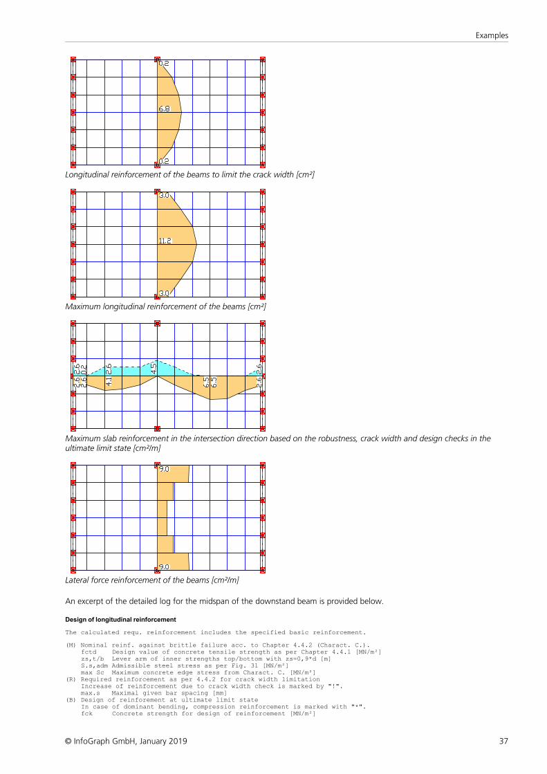
37
Examples
© InfoGraph GmbH, January 2019
Longitudinal reinforcement of the beams to limit the crack width [cm²]
Maximum longitudinal reinforcement of the beams [cm²]
Maximum slab reinforcement in the intersection direction based on the robustness, crack width and design checks in theultimate limit state [cm²/m]
Lateral force reinforcement of the beams [cm²/m]
An excerpt of the detailed log for the midspan of the downstand beam is provided below.
Design of longitudinal reinforcement The calculated requ. reinforcement includes the specified basic reinforcement. (M) Nominal reinf. against brittle failure acc. to Chapter 4.4.2 (Charact. C.). fctd Design value of concrete tensile strength as per Chapter 4.4.1 [MN/m²] zs,t/b Lever arm of inner strengths top/bottom with zs=0,9*d [m] S.s,adm Admissible steel stress as per Fig. 31 [MN/m²] max Sc Maximum concrete edge stress from Charact. C. [MN/m²](R) Required reinforcement as per 4.4.2 for crack width limitation Increase of reinforcement due to crack width check is marked by "!". max.s Maximal given bar spacing [mm](B) Design of reinforement at ultimate limit state In case of dominant bending, compression reinforcement is marked with "*". fck Concrete strength for design of reinforcement [MN/m²]
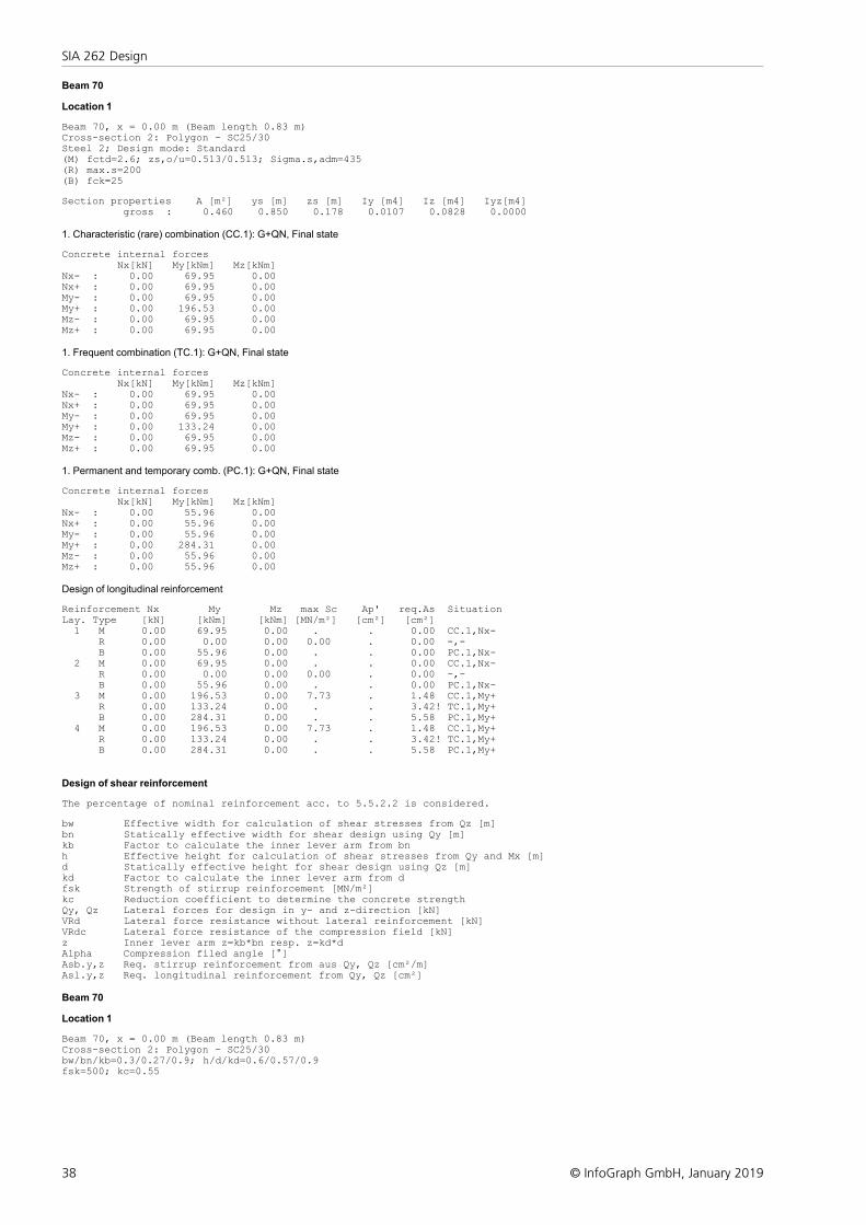
38
SIA 262 Design
© InfoGraph GmbH, January 2019
Beam 70
Location 1 Beam 70, x = 0.00 m (Beam length 0.83 m)Cross-section 2: Polygon - SC25/30Steel 2; Design mode: Standard(M) fctd=2.6; zs,o/u=0.513/0.513; Sigma.s,adm=435(R) max.s=200(B) fck=25 Section properties A [m²] ys [m] zs [m] Iy [m4] Iz [m4] Iyz[m4] gross : 0.460 0.850 0.178 0.0107 0.0828 0.0000
1. Characteristic (rare) combination (CC.1): G+QN, Final state Concrete internal forces Nx[kN] My[kNm] Mz[kNm]Nx- : 0.00 69.95 0.00Nx+ : 0.00 69.95 0.00My- : 0.00 69.95 0.00My+ : 0.00 196.53 0.00Mz- : 0.00 69.95 0.00Mz+ : 0.00 69.95 0.00
1. Frequent combination (TC.1): G+QN, Final state Concrete internal forces Nx[kN] My[kNm] Mz[kNm]Nx- : 0.00 69.95 0.00Nx+ : 0.00 69.95 0.00My- : 0.00 69.95 0.00My+ : 0.00 133.24 0.00Mz- : 0.00 69.95 0.00Mz+ : 0.00 69.95 0.00
1. Permanent and temporary comb. (PC.1): G+QN, Final state Concrete internal forces Nx[kN] My[kNm] Mz[kNm]Nx- : 0.00 55.96 0.00Nx+ : 0.00 55.96 0.00My- : 0.00 55.96 0.00My+ : 0.00 284.31 0.00Mz- : 0.00 55.96 0.00Mz+ : 0.00 55.96 0.00
Design of longitudinal reinforcement Reinforcement Nx My Mz max Sc Ap' req.As SituationLay. Type [kN] [kNm] [kNm] [MN/m²] [cm²] [cm²] 1 M 0.00 69.95 0.00 . . 0.00 CC.1,Nx- R 0.00 0.00 0.00 0.00 . 0.00 -,- B 0.00 55.96 0.00 . . 0.00 PC.1,Nx- 2 M 0.00 69.95 0.00 . . 0.00 CC.1,Nx- R 0.00 0.00 0.00 0.00 . 0.00 -,- B 0.00 55.96 0.00 . . 0.00 PC.1,Nx- 3 M 0.00 196.53 0.00 7.73 . 1.48 CC.1,My+ R 0.00 133.24 0.00 . . 3.42! TC.1,My+ B 0.00 284.31 0.00 . . 5.58 PC.1,My+ 4 M 0.00 196.53 0.00 7.73 . 1.48 CC.1,My+ R 0.00 133.24 0.00 . . 3.42! TC.1,My+ B 0.00 284.31 0.00 . . 5.58 PC.1,My+
Design of shear reinforcement The percentage of nominal reinforcement acc. to 5.5.2.2 is considered. bw Effective width for calculation of shear stresses from Qz [m]bn Statically effective width for shear design using Qy [m]kb Factor to calculate the inner lever arm from bnh Effective height for calculation of shear stresses from Qy and Mx [m]d Statically effective height for shear design using Qz [m]kd Factor to calculate the inner lever arm from dfsk Strength of stirrup reinforcement [MN/m²]kc Reduction coefficient to determine the concrete strengthQy, Qz Lateral forces for design in y- and z-direction [kN]VRd Lateral force resistance without lateral reinforcement [kN]VRdc Lateral force resistance of the compression field [kN]z Inner lever arm z=kb*bn resp. z=kd*dAlpha Compression filed angle [°]Asb.y,z Req. stirrup reinforcement from aus Qy, Qz [cm²/m]Asl.y,z Req. longitudinal reinforcement from Qy, Qz [cm²]
Beam 70
Location 1 Beam 70, x = 0.00 m (Beam length 0.83 m)Cross-section 2: Polygon - SC25/30bw/bn/kb=0.3/0.27/0.9; h/d/kd=0.6/0.57/0.9fsk=500; kc=0.55
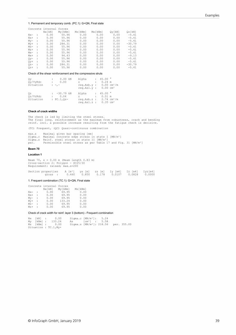
39
Examples
© InfoGraph GmbH, January 2019
1. Permanent and temporary comb. (PC.1): G+QN, Final state Concrete internal forces Nx[kN] My[kNm] Mz[kNm] Mx[kNm] Qy[kN] Qz[kN]Nx- : 0.00 55.96 0.00 0.00 0.00 -5.41Nx+ : 0.00 55.96 0.00 0.00 0.00 -5.41My- : 0.00 55.96 0.00 0.00 0.00 -5.41My+ : 0.00 284.31 0.00 0.00 0.00 -30.79Mz- : 0.00 55.96 0.00 0.00 0.00 -5.41Mz+ : 0.00 55.96 0.00 0.00 0.00 -5.41Mx- : 0.00 55.96 0.00 0.00 0.00 -5.41Mx+ : 0.00 94.43 0.00 0.00 0.00 -9.13Qy- : 0.00 55.96 0.00 0.00 0.00 -5.41Qy+ : 0.00 55.96 0.00 0.00 0.00 -5.41Qz- : 0.00 284.31 0.00 0.00 0.00 -30.79Qz+ : 0.00 55.96 0.00 0.00 0.00 -5.41
Check of the shear reinforcement and the compressive struts Qy : 0.00 kN Alpha : 45.00 °Qy/VyRdc : 0.00 z : 0.24 mSituation : -,- req.Asb.y : 0.00 cm²/m req.Asl.y : 0.00 cm² Qz : -30.79 kN Alpha : 45.00 °Qz/VzRdc : 0.04 z : 0.51 mSituation : PC.1,Qz- req.Asb.z : 2.74 cm²/m req.Asl.z : 0.35 cm²
Check of crack widths The check is led by limiting the steel stress.The final long. reinforcement as the maximum from robustness, crack and bendingreinf. incl. a possible increase resulting from the fatigue check is decisive. (TC) Frequent, (QC) Quasi-continuous combination max.s Maximal given bar spacing [mm]Sigma.c Maximal concrete edge stress in state I [MN/m²]Sigma.s Reinf. steel stress in state II [MN/m²]per. Permissible steel stress as per Table 17 and Fig. 31 [MN/m²]
Beam 70
Location 1 Beam 70, x = 0.00 m (Beam length 0.83 m)Cross-section 2: Polygon - SC25/30Requirement: raised; max.s=200 Section properties A [m²] ys [m] zs [m] Iy [m4] Iz [m4] Iyz[m4] gross : 0.460 0.850 0.178 0.0107 0.0828 0.0000
1. Frequent combination (TC.1): G+QN, Final state Concrete internal forces Nx[kN] My[kNm] Mz[kNm]Nx- : 0.00 69.95 0.00Nx+ : 0.00 69.95 0.00My- : 0.00 69.95 0.00My+ : 0.00 133.24 0.00Mz- : 0.00 69.95 0.00Mz+ : 0.00 69.95 0.00
Check of crack width for reinf. layer 3 (bottom) - Frequent combination Nx [kN] : 0.00 Sigma.c [MN/m²]: 5.24My [kNm] : 133.24 As [cm²] : 5.58Mz [kNm] : 0.00 Sigma.s [MN/m²]: 218.56 per. 355.00Situation : TC.1,My+
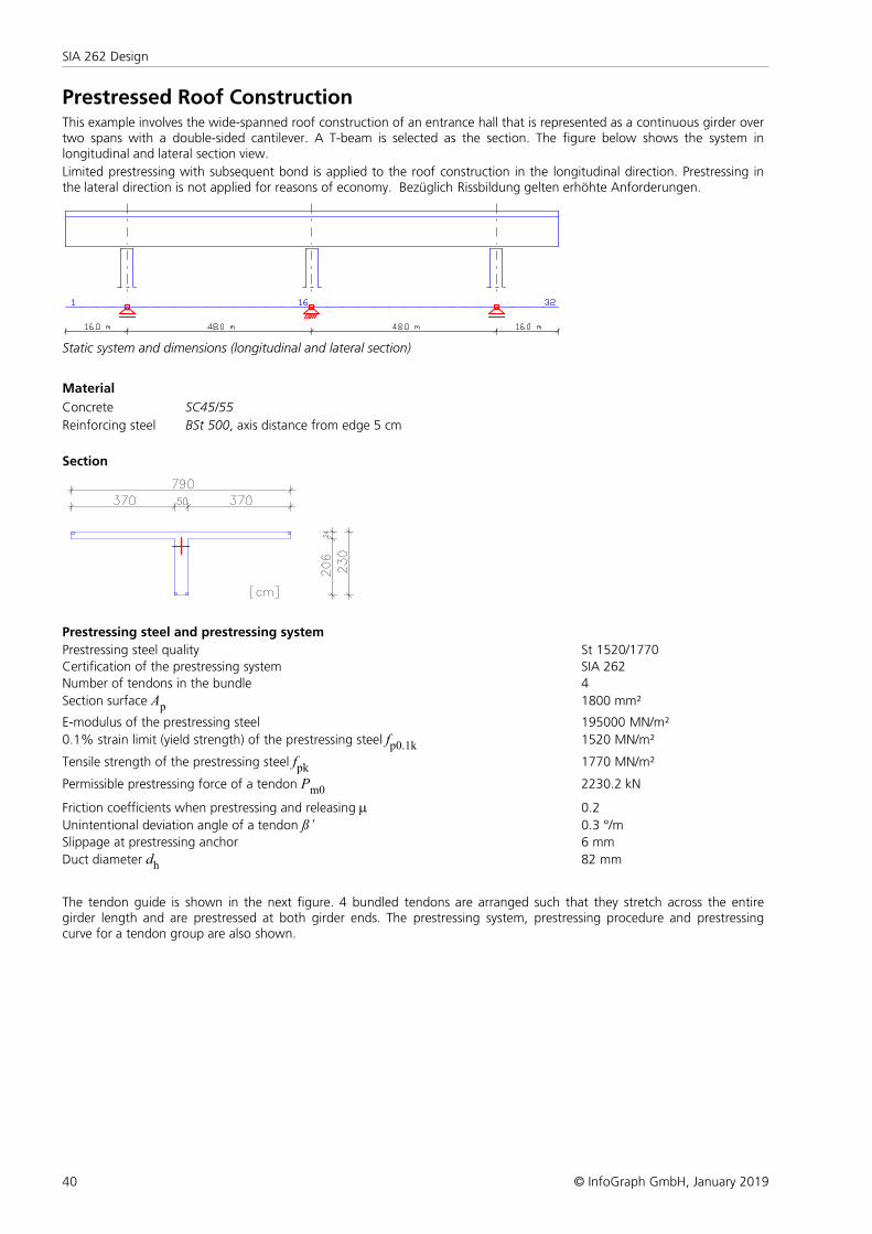
40
SIA 262 Design
© InfoGraph GmbH, January 2019
Prestressed Roof ConstructionThis example involves the wide-spanned roof construction of an entrance hall that is represented as a continuous girder overtwo spans with a double-sided cantilever. A T-beam is selected as the section. The figure below shows the system inlongitudinal and lateral section view.
Limited prestressing with subsequent bond is applied to the roof construction in the longitudinal direction. Prestressing inthe lateral direction is not applied for reasons of economy. Bezüglich Rissbildung gelten erhöhte Anforderungen.
Static system and dimensions (longitudinal and lateral section)
Material
Concrete SC45/55
Reinforcing steel BSt 500, axis distance from edge 5 cm
Section
Prestressing steel and prestressing system
Prestressing steel quality St 1520/1770
Certification of the prestressing system SIA 262
Number of tendons in the bundle 4
Section surface Ap 1800 mm²
E-modulus of the prestressing steel 195000 MN/m²
0.1% strain limit (yield strength) of the prestressing steel fp0.1k 1520 MN/m²
Tensile strength of the prestressing steel fpk 1770 MN/m²
Permissible prestressing force of a tendon Pm0 2230.2 kN
Friction coefficients when prestressing and releasing m 0.2
Unintentional deviation angle of a tendon ß’ 0.3 °/m
Slippage at prestressing anchor 6 mm
Duct diameter dh 82 mm
The tendon guide is shown in the next figure. 4 bundled tendons are arranged such that they stretch across the entiregirder length and are prestressed at both girder ends. The prestressing system, prestressing procedure and prestressingcurve for a tendon group are also shown.
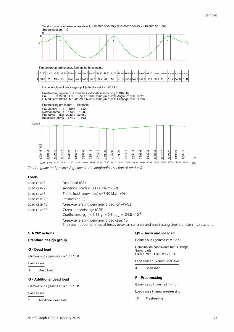
41
Examples
© InfoGraph GmbH, January 2019
00
Tendon groups in beam series view 1, [-16.00/0.00/0.00] - [112.00/0.00/0.00] / [-16.00/0.00/1.00]Superelevation = 10
Tendon group ordinates zv [cm] at the base points
xv 0.00 6.40 12.80 19.20 25.60 32.00 38.40 44.80 51.20 57.60 64.00 70.40 76.80 83.20 89.60 96.00 102.40 108.80 115.20 121.60 128.00
1 70.0 52.0 19.2 42.0 120.2 180.1 208.8 201.5 157.4 78.3 18.5 78.3 157.4 201.5 208.8 180.1 120.2 42.0 19.2 52.0 70.0
Force function of tendon group 1 (4 tendon(s), l = 128.41 m)
Prestressing system 1 - Example. Certification according to SIA 262.Pm0 = 2230.2 kN, Ap = 1800.0 mm², µa = 0.20, Angle ß' = 0.30 °/mE-Modulus= 195000 MN/m², Ah = 5281.0 mm², µn = 0.20, Slippage = 6.00 mm
Prestressing procedure 1 - Example
Pre. anchor : Start EndNormal. force : 1.000 1.000Pre. force [kN]: 2230.2 2230.2Extension [mm]: 674.9 70.8
8466.4
xv
[m]0.00
8084.5
[kN
]
6.40
8196.3
12.80
8324.2
19.20
8379.7
25.60
8266.3
32.00
8137.2
38.40
7996.6
44.80
7851.3
51.20
7712.1
57.60
7593.9
64.00
7342.6
70.40
7593.9
76.80
7712.1
83.20
7851.3
89.60
7996.6
96.00
8137.2
102.40
8266.3
108.808379.7
115.20
8324.2
121.60
8196.3
128.00
8084.5
Tendon guide and prestressing curve in the longitudinal section (4 tendons).
Loads
Load case 1 Dead load (G1).
Load case 2 Additional loads q=11.06 kN/m (G2).
Load case 3 Traffic load (snow load) q=7.90 kN/m (Q).
Load case 10 Prestressing (P).
Load case 15 Creep-generating permanent load: G1+P+G2
Load case 20 Creep and shrinkage (CSR).
Coefficients: jt¥ = 2.55; r = 0.8; et¥ = -24.8 · 10-5
Creep-generating permanent load case: 15The redistribution of internal forces between concrete and prestressing steel are taken into account.
SIA 262 actions
Standard design group
G - Dead load
Gamma.sup / gamma.inf = 1.35 / 0.8
Load cases
1 Dead load
G - Additional dead load
Gamma.sup / gamma.inf = 1.35 / 0.8
Load cases
2 Additional dead load
QS - Snow and ice load
Gamma.sup / gamma.inf = 1.5 / 0
Combination coefficients for: Buildings Snow loads Psi.0 / Psi.1 / Psi.2 = 1 / 1 / 1
Load cases 1. Variant, inclusive
3 Snow load
P - Prestressing
Gamma.sup / gamma.inf = 1 / 1
Load cases internal prestressing
10 Prestressing
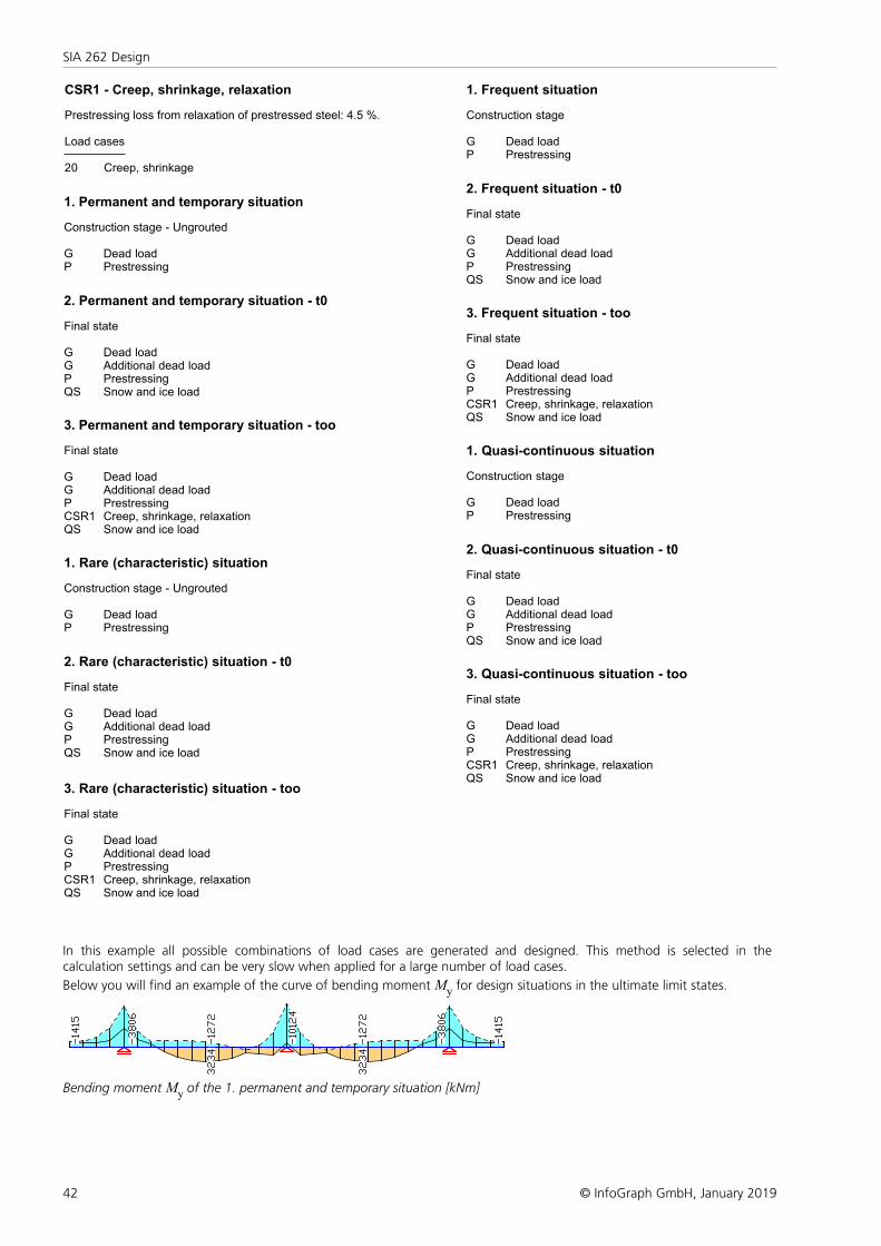
42
SIA 262 Design
© InfoGraph GmbH, January 2019
CSR1 - Creep, shrinkage, relaxation
Prestressing loss from relaxation of prestressed steel: 4.5 %.
Load cases
20 Creep, shrinkage
1. Permanent and temporary situation
Construction stage - Ungrouted
G Dead loadP Prestressing
2. Permanent and temporary situation - t0
Final state
G Dead loadG Additional dead loadP PrestressingQS Snow and ice load
3. Permanent and temporary situation - too
Final state
G Dead loadG Additional dead loadP PrestressingCSR1 Creep, shrinkage, relaxationQS Snow and ice load
1. Rare (characteristic) situation
Construction stage - Ungrouted
G Dead loadP Prestressing
2. Rare (characteristic) situation - t0
Final state
G Dead loadG Additional dead loadP PrestressingQS Snow and ice load
3. Rare (characteristic) situation - too
Final state
G Dead loadG Additional dead loadP PrestressingCSR1 Creep, shrinkage, relaxationQS Snow and ice load
1. Frequent situation
Construction stage
G Dead loadP Prestressing
2. Frequent situation - t0
Final state
G Dead loadG Additional dead loadP PrestressingQS Snow and ice load
3. Frequent situation - too
Final state
G Dead loadG Additional dead loadP PrestressingCSR1 Creep, shrinkage, relaxationQS Snow and ice load
1. Quasi-continuous situation
Construction stage
G Dead loadP Prestressing
2. Quasi-continuous situation - t0
Final state
G Dead loadG Additional dead loadP PrestressingQS Snow and ice load
3. Quasi-continuous situation - too
Final state
G Dead loadG Additional dead loadP PrestressingCSR1 Creep, shrinkage, relaxationQS Snow and ice load
In this example all possible combinations of load cases are generated and designed. This method is selected in thecalculation settings and can be very slow when applied for a large number of load cases.
Below you will find an example of the curve of bending moment My for design situations in the ultimate limit states.
Bending moment My of the 1. permanent and temporary situation [kNm]
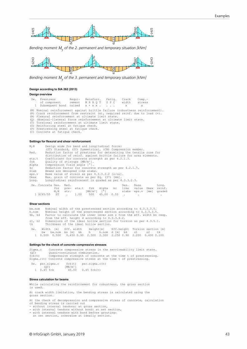
43
Examples
© InfoGraph GmbH, January 2019
Bending moment My of the 2. permanent and temporary situation [kNm]
Bending moment My of the 3. permanent and temporary situation [kNm]
Design according to SIA 262 (2013)
Design overview
Se. Prestress Requi- Reinforc. Fatig. Crack Comp.- of component rement M R B Q T S P C width stress 1 Subsequent bond raised x + x x . . . . x x
(M) Nominal reinforcement against brittle failure (robustness reinforcement).(R) Crack reinforcement from restraint (x), required reinf. due to load (+).(B) Flexural reinforcement at ultimate limit state.(Q) (Nominal-)lateral force reinforcement at ultimate limit state.(T) Torsional reinforcement at ultimate limit state.(S) Reinforcing steel at fatigue check.(P) Prestressing steel at fatigue check.(C) Concrete at fatigue check.
Settings for flexural and shear reinforcement
M,N Design mode for bend and longitudinal force: (ST) Standard, (SY) Symmetrical, (CM) Compression member.Red. Reduction factor of prestress for determining the tensile zone for distribution of reinf. against brittle failure for area elements.eta.t Coefficient for concrete strength as per 4.2.1.3.fsk Quality of stirrups [MN/m²].Alpha Compression field angle [°].kc Reduction factor for concrete strength as per 4.2.1.7.Slab Beams are designed like slabs.eps.v Base value of strain as per 4.3.3.2.2 [o/oo].Dmax Max. grain of concrete as per Eq. (37) [mm].Long. Longitudinal reinforecent is graded as per 4.3.3.2.3.
Se. Concrete Des. Red. Des. Base Long. for pre- eta.t fsk Alpha kc like value Dmax reinf. M,N str. [MN/m²] [°] slabs eps.v [mm] graded 1 SC45/55 ST . 1.00 500 45.00 0.55 . . .
Shear sections
bw.nom Nominal width of the prestressed section according to 4.3.3.3.5.h.nom Nominal height of the prestressed section according to 4.3.3.3.5.kb, kd Factor to calculate the inner lever arm z from the eff. width bn resp. from the eff. height d according to 4.3.3.4.2.z1, z2 Dimensions of the ideal hollow section for torsion as per 4.3.5.1.tk Thickness of the ideal hollow section.
Se. Width [m] Eff. width Height[m] Eff.height Torsion section [m] bw bw.nom bn [m] kb h h.nom d [m] kd z1 z2 tk 1 0.500 0.500 0.450 0.90 2.300 2.300 2.250 0.90 2.200 0.400 0.100
Settings for the check of concrete compressive stresses
Sigma.c Concrete compressive stress in the serviceability limit state.(QC) Quasi-continuous combination.fck(t) Compressive strength of concrete at the time t of prestressing.Sigma.c(t) Concrete compressive stress at the time t of prestressing.
Se. per.sigma.c fck(t) per.sigma.c(t) (QC) [MN/m²] 1 0.45 fck 45.00 0.45 fck(t)
Stress calculation for beams
While calculating the reinforcement for robustness, the gross sectionis used.
At crack width limitation, the bending stress is calculated using thegross section.
At the check of decompression and compressive stress of concrete, calculationof bending stress is carried out- without internal tendons: at gross section,- with internal tendons without bond: at net section,- with internal tendons with bond before grouting: at net section, otherwise at ideally section.
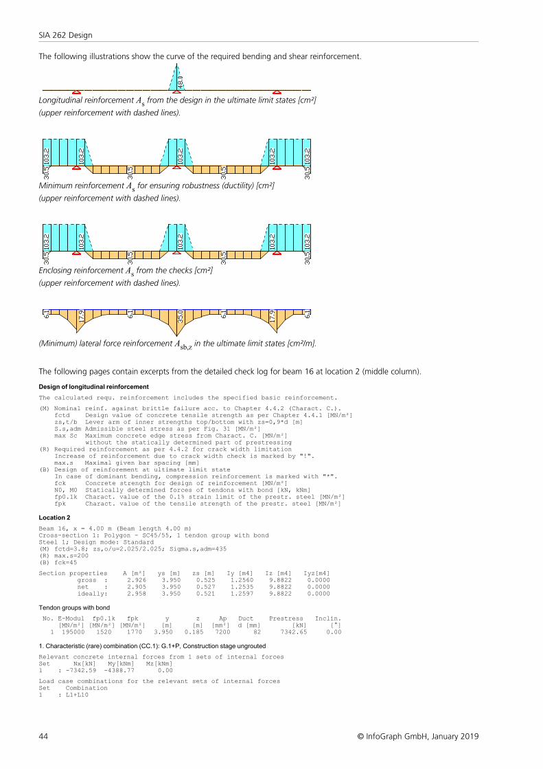
44
SIA 262 Design
© InfoGraph GmbH, January 2019
The following illustrations show the curve of the required bending and shear reinforcement.
Longitudinal reinforcement As from the design in the ultimate limit states [cm²]
(upper reinforcement with dashed lines).
Minimum reinforcement As for ensuring robustness (ductility) [cm²]
(upper reinforcement with dashed lines).
Enclosing reinforcement As from the checks [cm²]
(upper reinforcement with dashed lines).
(Minimum) lateral force reinforcement Asb,z in the ultimate limit states [cm²/m].
The following pages contain excerpts from the detailed check log for beam 16 at location 2 (middle column).
Design of longitudinal reinforcement
The calculated requ. reinforcement includes the specified basic reinforcement.
(M) Nominal reinf. against brittle failure acc. to Chapter 4.4.2 (Charact. C.). fctd Design value of concrete tensile strength as per Chapter 4.4.1 [MN/m²] zs,t/b Lever arm of inner strengths top/bottom with zs=0,9*d [m] S.s,adm Admissible steel stress as per Fig. 31 [MN/m²] max Sc Maximum concrete edge stress from Charact. C. [MN/m²] without the statically determined part of prestressing(R) Required reinforcement as per 4.4.2 for crack width limitation Increase of reinforcement due to crack width check is marked by "!". max.s Maximal given bar spacing [mm](B) Design of reinforement at ultimate limit state In case of dominant bending, compression reinforcement is marked with "*". fck Concrete strength for design of reinforcement [MN/m²] N0, M0 Statically determined forces of tendons with bond [kN, kNm] fp0.1k Charact. value of the 0.1% strain limit of the prestr. steel [MN/m²] fpk Charact. value of the tensile strength of the prestr. steel [MN/m²]
Location 2
Beam 16, x = 4.00 m (Beam length 4.00 m)Cross-section 1: Polygon - SC45/55, 1 tendon group with bondSteel 1; Design mode: Standard(M) fctd=3.8; zs,o/u=2.025/2.025; Sigma.s,adm=435(R) max.s=200(B) fck=45
Section properties A [m²] ys [m] zs [m] Iy [m4] Iz [m4] Iyz[m4] gross : 2.926 3.950 0.525 1.2560 9.8822 0.0000 net : 2.905 3.950 0.527 1.2535 9.8822 0.0000 ideally: 2.958 3.950 0.521 1.2597 9.8822 0.0000
Tendon groups with bond
No. E-Modul fp0.1k fpk y z Ap Duct Prestress Inclin. [MN/m²] [MN/m²] [MN/m²] [m] [m] [mm²] d [mm] [kN] [°] 1 195000 1520 1770 3.950 0.185 7200 82 7342.65 0.00
1. Characteristic (rare) combination (CC.1): G.1+P, Construction stage ungrouted
Relevant concrete internal forces from 1 sets of internal forcesSet Nx[kN] My[kNm] Mz[kNm]1 : -7342.59 -4388.77 0.00
Load case combinations for the relevant sets of internal forcesSet Combination1 : L1+L10
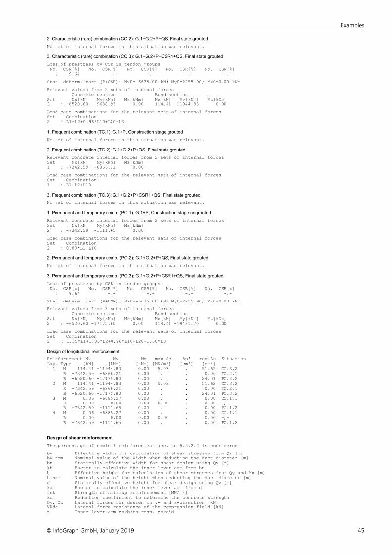
45
Examples
© InfoGraph GmbH, January 2019
2. Characteristic (rare) combination (CC.2): G.1+G.2+P+QS, Final state grouted
No set of internal forces in this situation was relevant.
3. Characteristic (rare) combination (CC.3): G.1+G.2+P+CSR1+QS, Final state grouted
Loss of prestress by CSR in tendon groups No. CSR[%] No. CSR[%] No. CSR[%] No. CSR[%] No. CSR[%] 1 9.64 -.- -.- -.- -.-
Stat. determ. part (P+CSR): Nx0=-6635.00 kN; My0=2255.90; Mz0=0.00 kNm
Relevant values from 2 sets of internal forces Concrete section Bond sectionSet Nx[kN] My[kNm] Mz[kNm] Nx[kN] My[kNm] Mz[kNm]2 : -6520.60 -9688.93 0.00 114.41 -11944.83 0.00
Load case combinations for the relevant sets of internal forcesSet Combination2 : L1+L2+0.96*L10+L20+L3
1. Frequent combination (TC.1): G.1+P, Construction stage grouted
No set of internal forces in this situation was relevant.
2. Frequent combination (TC.2): G.1+G.2+P+QS, Final state grouted
Relevant concrete internal forces from 2 sets of internal forcesSet Nx[kN] My[kNm] Mz[kNm]1 : -7342.59 -6866.21 0.00
Load case combinations for the relevant sets of internal forcesSet Combination1 : L1+L2+L10
3. Frequent combination (TC.3): G.1+G.2+P+CSR1+QS, Final state grouted
No set of internal forces in this situation was relevant.
1. Permanent and temporary comb. (PC.1): G.1+P, Construction stage ungrouted
Relevant concrete internal forces from 2 sets of internal forcesSet Nx[kN] My[kNm] Mz[kNm]2 : -7342.59 -1111.65 0.00
Load case combinations for the relevant sets of internal forcesSet Combination2 : 0.80*L1+L10
2. Permanent and temporary comb. (PC.2): G.1+G.2+P+QS, Final state grouted
No set of internal forces in this situation was relevant.
3. Permanent and temporary comb. (PC.3): G.1+G.2+P+CSR1+QS, Final state grouted
Loss of prestress by CSR in tendon groups No. CSR[%] No. CSR[%] No. CSR[%] No. CSR[%] No. CSR[%] 1 9.64 -.- -.- -.- -.-
Stat. determ. part (P+CSR): Nx0=-6635.00 kN; My0=2255.90; Mz0=0.00 kNm
Relevant values from 8 sets of internal forces Concrete section Bond sectionSet Nx[kN] My[kNm] Mz[kNm] Nx[kN] My[kNm] Mz[kNm]2 : -6520.60 -17175.80 0.00 114.41 -19431.70 0.00
Load case combinations for the relevant sets of internal forcesSet Combination2 : 1.35*L1+1.35*L2+0.96*L10+L20+1.50*L3
Design of longitudinal reinforcement
Reinforcement Nx My Mz max Sc Ap' req.As SituationLay. Type [kN] [kNm] [kNm] [MN/m²] [cm²] [cm²] 1 M 114.41 -11944.83 0.00 5.03 . 51.62 CC.3,2 R -7342.59 -6866.21 0.00 . . 0.00 TC.2,1 B -6520.60 -17175.80 0.00 . . 24.01 PC.3,2 2 M 114.41 -11944.83 0.00 5.03 . 51.62 CC.3,2 R -7342.59 -6866.21 0.00 . . 0.00 TC.2,1 B -6520.60 -17175.80 0.00 . . 24.01 PC.3,2 3 M 0.06 -6885.27 0.00 . . 0.00 CC.1,1 R 0.00 0.00 0.00 0.00 . 0.00 -,- B -7342.59 -1111.65 0.00 . . 0.00 PC.1,2 4 M 0.06 -6885.27 0.00 . . 0.00 CC.1,1 R 0.00 0.00 0.00 0.00 . 0.00 -,- B -7342.59 -1111.65 0.00 . . 0.00 PC.1,2
Design of shear reinforcement
The percentage of nominal reinforcement acc. to 5.5.2.2 is considered.
bw Effective width for calculation of shear stresses from Qz [m]bw.nom Nominal value of the width when deducting the duct diameter [m]bn Statically effective width for shear design using Qy [m]kb Factor to calculate the inner lever arm from bnh Effective height for calculation of shear stresses from Qy and Mx [m]h.nom Nominal value of the height when deducting the duct diameter [m]d Statically effective height for shear design using Qz [m]kd Factor to calculate the inner lever arm from dfsk Strength of stirrup reinforcement [MN/m²]kc Reduction coefficient to determine the concrete strengthQy, Qz Lateral forces for design in y- and z-direction [kN]VRdc Lateral force resistance of the compression field [kN]z Inner lever arm z=kb*bn resp. z=kd*d
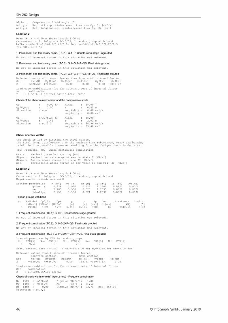
46
SIA 262 Design
© InfoGraph GmbH, January 2019
Alpha Compression field angle [°]Asb.y,z Req. stirrup reinforcement from aus Qy, Qz [cm²/m]Asl.y,z Req. longitudinal reinforcement from Qy, Qz [cm²]
Location 2
Beam 16, x = 4.00 m (Beam length 4.00 m)Cross-section 1: Polygon - SC45/55, 1 tendon group with bondbw/bw.nom/bn/kb=0.5/0.5/0.45/0.9; h/h.nom/d/kd=2.3/2.3/2.25/0.9fsk=500; kc=0.55
1. Permanent and temporary comb. (PC.1): G.1+P, Construction stage ungrouted
No set of internal forces in this situation was relevant.
2. Permanent and temporary comb. (PC.2): G.1+G.2+P+QS, Final state grouted
No set of internal forces in this situation was relevant.
3. Permanent and temporary comb. (PC.3): G.1+G.2+P+CSR1+QS, Final state grouted
Relevant concrete internal forces from 8 sets of internal forcesSet Nx[kN] My[kNm] Mz[kNm] Mx[kNm] Qy[kN] Qz[kN]2 : -6520.60 -17175.80 0.00 0.00 0.00 -3078.27
Load case combinations for the relevant sets of internal forcesSet Combination2 : 1.35*L1+1.35*L2+0.96*L10+L20+1.50*L3
Check of the shear reinforcement and the compressive struts
Qy : 0.00 kN Alpha : 45.00 °Qy/VyRdc : 0.00 z : 0.41 mSituation : -,- req.Asb.y : 0.00 cm²/m req.Asl.y : 0.00 cm²
Qz :-3078.27 kN Alpha : 45.00 °Qz/VzRdc : 0.42 z : 2.02 mSituation : PC.3,2 req.Asb.z : 34.96 cm²/m req.Asl.z : 35.40 cm²
Check of crack widths
The check is led by limiting the steel stress.The final long. reinforcement as the maximum from robustness, crack and bendingreinf. incl. a possible increase resulting from the fatigue check is decisive.
(TC) Frequent, (QC) Quasi-continuous combination
max.s Maximal given bar spacing [mm]Sigma.c Maximal concrete edge stress in state I [MN/m²]Sigma.s Reinf. steel stress in state II [MN/m²]per. Permissible steel stress as per Table 17 and Fig. 31 [MN/m²]
Location 2
Beam 16, x = 4.00 m (Beam length 4.00 m)Cross-section 1: Polygon - SC45/55, 1 tendon group with bondRequirement: raised; max.s=200
Section properties A [m²] ys [m] zs [m] Iy [m4] Iz [m4] Iyz[m4] gross : 2.926 3.950 0.525 1.2560 9.8822 0.0000 net : 2.905 3.950 0.527 1.2535 9.8822 0.0000 ideally: 2.958 3.950 0.521 1.2597 9.8822 0.0000
Tendon groups with bond
No. E-Modul fp0,1k fpk y z Ap Duct Prestress Inclin. [MN/m²] [MN/m²] [MN/m²] [m] [m] [mm²] d [mm] [kN] [°] 1 195000 1520 1770 3.950 0.185 7200 82 7342.65 0.00
1. Frequent combination (TC.1): G.1+P, Construction stage grouted
No set of internal forces in this situation was relevant.
2. Frequent combination (TC.2): G.1+G.2+P+QS, Final state grouted
No set of internal forces in this situation was relevant.
3. Frequent combination (TC.3): G.1+G.2+P+CSR1+QS, Final state grouted
Loss of prestress by CSR in tendon groups No. CSR[%] No. CSR[%] No. CSR[%] No. CSR[%] No. CSR[%] 1 9.64 -.- -.- -.- -.-
Stat. determ. part (P+CSR) : Nx0=-6635.00 kN; My0=2255.90; Mz0=0.00 kNm
Relevant values from 2 sets of internal forces Concrete section Bond sectionSet Nx[kN] My[kNm] Mz[kNm] Nx[kN] My[kNm] Mz[kNm]2 : -6520.60 -9688.93 0.00 114.41 -11944.83 0.00
Load case combinations for the relevant sets of internal forcesSet Combination2 : L1+L2+0.96*L10+L20+L3
Check of crack width for reinf. layer 2 (top) - Frequent combination
Nx [kN] : -6520.60 Sigma.c [MN/m²]: 1.82My [kNm] : -9688.93 As [cm²] : 51.62Mz [kNm] : 0.00 Sigma.s [MN/m²]: 63.71 per. 355.00Situation : TC.3,2
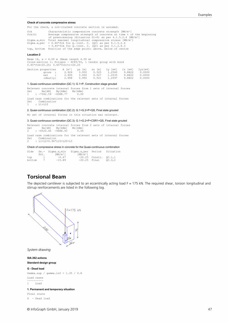
47
Examples
© InfoGraph GmbH, January 2019
Check of concrete compressive stress
For the check, a non-cracked concrete section is assumed.
fck Characteristic compressive concrete strength [MN/m²]fck(t) Average compressive strength of concrete at time t of the beginning of prestressing (Situation G1+P) as per 4.1.5.2.4 [MN/m²]Sigma.x,min Total maximal longitudinal compressive stress [MN/m²]Sigma.x,per = 0.60*fck for Q.-cont. C. (QC) as per 4.1.5.2.4 = 0.45*fck for Q.-cont. C. (QC) as per 3.1.2.6.3top, bottom Position of the edge point: above, below of centre
Location 2
Beam 16, x = 4.00 m (Beam length 4.00 m)Cross-section 1: Polygon - SC45/55, 1 tendon group with bond0.45*fck=20.25; 0.45*fck(t)=20.25
Section properties A [m²] ys [m] zs [m] Iy [m4] Iz [m4] Iyz[m4] gross : 2.926 3.950 0.525 1.2560 9.8822 0.0000 net : 2.905 3.950 0.527 1.2535 9.8822 0.0000 ideally: 2.958 3.950 0.521 1.2597 9.8822 0.0000
1. Quasi-continuous combination (QC.1): G.1+P, Construction stage grouted
Relevant concrete internal forces from 1 sets of internal forcesSet Nx[kN] My[kNm] Mz[kNm]1 : -7342.59 -4388.77 0.00
Load case combinations for the relevant sets of internal forcesSet Combination1 : L1+L10
2. Quasi-continuous combination (QC.2): G.1+G.2+P+QS, Final state grouted
No set of internal forces in this situation was relevant.
3. Quasi-continuous combination (QC.3): G.1+G.2+P+CSR1+QS, Final state grouted
Relevant concrete internal forces from 2 sets of internal forcesSet Nx[kN] My[kNm] Mz[kNm]2 : -6520.60 -9688.93 0.00
Load case combinations for the relevant sets of internal forcesSet Combination2 : L1+L2+0.96*L10+L20+L3
Check of compressive stress in concrete for the Quasi-continuous combination
Side Se.- Sigma.x,min Sigma.x,per Period Situation Pnt. [MN/m²] [MN/m²]top 1 -0.67 -20.25 Constr. QC.1,1 bottom 7 -15.89 -20.25 Final QC.3,2
Torsional BeamThe depicted cantilever is subjected to an eccentrically acting load F = 175 kN. The required shear, torsion longitudinal andstirrup reinforcements are listed in the following log.
System drawing
SIA 262 actions
Standard design group
G - Dead load
Gamma.sup / gamma.inf = 1.35 / 0.8
Load cases----------1 Load
1. Permanent and temporary situation
Final state
G - Dead load
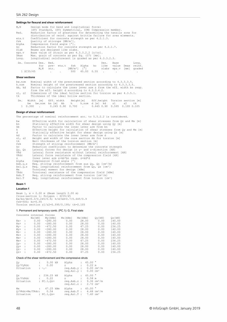
48
SIA 262 Design
© InfoGraph GmbH, January 2019
Settings for flexural and shear reinforcement
M,N Design mode for bend and longitudinal force: (ST) Standard, (SY) Symmetrical, (CM) Compression member.Red. Reduction factor of prestress for determining the tensile zone for distribution of reinf. against brittle failure for area elements.eta.t Coefficient for concrete strength as per 4.2.1.3.fsk Quality of stirrups [MN/m²].Alpha Compression field angle [°].kc Reduction factor for concrete strength as per 4.2.1.7.Slab Beams are designed like slabs.eps.v Base value of strain as per 4.3.3.2.2 [o/oo].Dmax Max. grain of concrete as per Eq. (37) [mm].Long. Longitudinal reinforecent is graded as per 4.3.3.2.3.
Se. Concrete Des. Red. Des. Base Long. for pre- eta.t fsk Alpha kc like value Dmax reinf. M,N str. [MN/m²] [°] slabs eps.v [mm] graded 1 SC35/45 . . 500 45.00 0.55 . . .
Shear sections
bw.nom Nominal width of the prestressed section according to 4.3.3.3.5.h.nom Nominal height of the prestressed section according to 4.3.3.3.5.kb, kd Factor to calculate the inner lever arm z from the eff. width bn resp. from the eff. height d according to 4.3.3.4.2.z1, z2 Dimensions of the ideal hollow section for torsion as per 4.3.5.1.tk Thickness of the ideal hollow section.
Se. Width [m] Eff. width Height[m] Eff.height Torsion section [m] bw bw.nom bn [m] kb h h.nom d [m] kd z1 z2 tk 1 0.300 . 0.245 0.90 0.700 . 0.645 0.90 0.595 0.195 0.105
Design of shear reinforcement
The percentage of nominal reinforcement acc. to 5.5.2.2 is considered.
bw Effective width for calculation of shear stresses from Qz and Mx [m]bn Statically effective width for shear design using Qy [m]kb Factor to calculate the inner lever arm from bnh Effective height for calculation of shear stresses from Qy and Mx [m]d Statically effective height for shear design using Qz [m]kd Factor to calculate the inner lever arm from dz1, z2 Height and width of the core section Ak for torsion [m]tk Wall thickness of the torsion section [m]fsk Strength of stirrup reinforcement [MN/m²]kc Reduction coefficient to determine the concrete strengthQy, Qz Lateral forces for design in y- and z-direction [kN]VRd Lateral force resistance without lateral reinforcement [kN]VRdc Lateral force resistance of the compression field [kN]z Inner lever arm z=kb*bn resp. z=kd*dAlpha Compression filed angle [°]Asb.y,z Req. stirrup reinforcement from aus Qy, Qz [cm²/m]Asl.y,z Req. longitudinal reinforcement from Qy, Qz [cm²]Mx Torsional moment for design [kNm]TRdc Torsional resistance of the compression field [kNm]Asb.T Req. stirrup reinforcement from torsion [cm²/m]Asl.T Req. longitudinal reinforcement from torsion [cm²]
Beam 1
Location 1
Beam 1, x = 0.00 m (Beam length 2.00 m)Cross-section 1: Polygon - SC35/45bw/bn/kb=0.3/0.245/0.9; h/d/kd=0.7/0.645/0.9fsk=500; kc=0.55Torsion section z1/z2=0.595/0.195; tk=0.105
1. Permanent and temporary comb. (PC.1): G, Final state
Concrete internal forces Nx[kN] My[kNm] Mz[kNm] Mx[kNm] Qy[kN] Qz[kN]Nx- : 0.00 -280.00 0.00 28.00 0.00 140.00Nx+ : 0.00 -280.00 0.00 28.00 0.00 140.00My- : 0.00 -472.50 0.00 47.25 0.00 236.25My+ : 0.00 -280.00 0.00 28.00 0.00 140.00Mz- : 0.00 -280.00 0.00 28.00 0.00 140.00Mz+ : 0.00 -280.00 0.00 28.00 0.00 140.00Mx- : 0.00 -280.00 0.00 28.00 0.00 140.00Mx+ : 0.00 -472.50 0.00 47.25 0.00 236.25Qy- : 0.00 -280.00 0.00 28.00 0.00 140.00Qy+ : 0.00 -280.00 0.00 28.00 0.00 140.00Qz- : 0.00 -280.00 0.00 28.00 0.00 140.00Qz+ : 0.00 -472.50 0.00 47.25 0.00 236.25
Check of the shear reinforcement and the compressive struts
Qy : 0.00 kN Alpha : 45.00 °Qy/VyRdc : 0.00 z : 0.22 mSituation : -,- req.Asb.y : 0.00 cm²/m req.Asl.y : 0.00 cm²
Qz : 236.25 kN Alpha : 45.00 °Qz/VzRdc : 0.22 z : 0.58 mSituation : PC.1,Qz+ req.Asb.z : 9.36 cm²/m req.Asl.z : 2.72 cm²
Mx : 47.25 kNm Alpha : 45.00 °Q/VRdc+Mx/TRdc: 0.54 req.Asb.T : 4.68 cm²/mSituation : PC.1,Qz+ req.Asl.T : 7.40 cm²
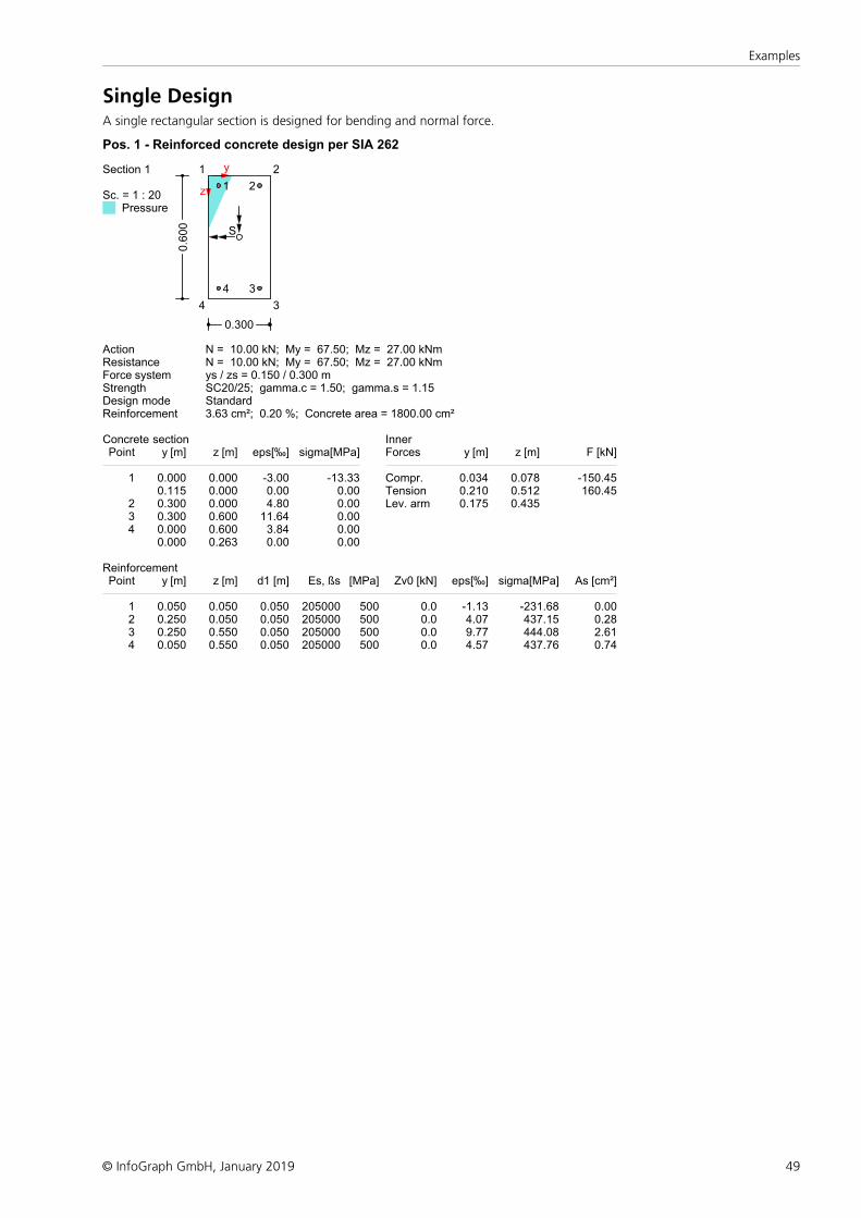
49
Examples
© InfoGraph GmbH, January 2019
Single DesignA single rectangular section is designed for bending and normal force.
Pos. 1 - Reinforced concrete design per SIA 262
Section 1
Sc. = 1 : 20Pressure
y
z
S
1 2
34
0.300
0.6
00
1 2
34
Action N = 10.00 kN; My = 67.50; Mz = 27.00 kNmResistance N = 10.00 kN; My = 67.50; Mz = 27.00 kNmForce system ys / zs = 0.150 / 0.300 mStrength SC20/25; gamma.c = 1.50; gamma.s = 1.15Design mode StandardReinforcement 3.63 cm²; 0.20 %; Concrete area = 1800.00 cm²
Concrete sectionPoint y [m] z [m] eps[‰] sigma[MPa]
InnerForces y [m] z [m] F [kN]
1 0.000 0.000 -3.00 -13.33 Compr. 0.034 0.078 -150.450.115 0.000 0.00 0.00 Tension 0.210 0.512 160.45
2 0.300 0.000 4.80 0.00 Lev. arm 0.175 0.4353 0.300 0.600 11.64 0.004 0.000 0.600 3.84 0.00
0.000 0.263 0.00 0.00
ReinforcementPoint y [m] z [m] d1 [m] Es, ßs [MPa] Zv0 [kN] eps[‰] sigma[MPa] As [cm²]
1 0.050 0.050 0.050 205000 500 0.0 -1.13 -231.68 0.002 0.250 0.050 0.050 205000 500 0.0 4.07 437.15 0.283 0.250 0.550 0.050 205000 500 0.0 9.77 444.08 2.614 0.050 0.550 0.050 205000 500 0.0 4.57 437.76 0.74
50
SIA 262 Design
© InfoGraph GmbH, January 2019
ReferencesDocumentation SIA D 0181
Grundlagen der Projektierung von Tragwerken (Basics of Planning for Structures),Einwirkungen auf Tragwerke (Actions on Structures),Einführung in die Normen SIA 260 und 261 (Introduction to the Standards SIA 260 and 261),Schweizerischer Ingenieur- und Architektenverein, Zürich 2003.
Documentation SIA D 0182Betonbau (Concrete Structures),Einführung in die Norm SIA 262 (Introduction to the Standard SIA 262),Schweizerischer Ingenieur- und Architektenverein, Zürich 2003.
Dokumentation SIA D 0240Erhaltung von Tragwerken - Vertiefung und Anwendung (Conservation of Structures - Consolidation and Practice)Schweizerischer Ingenieur- und Architektenverein, Zürich 2011.
EN 1992-1-1:2004/AC:2010Eurocode 2: Design of Concrete Structures –Part 1-1: General Rules and Rules for BuildingsPublisher: CEN European Committee for Standardization, Brussels.Beuth Verlag, Berlin 2010.
EN 1992-2:2005/AC:2008Eurocode 2: Design of Concrete Structures –Part 2: Concrete Bridges - Design and Detailing RulesPublisher: CEN European Committee for Standardization, Brussels.Beuth Verlag, Berlin 2010.
SIA 260:2013 BauwesenGrundlagen der Projektierung von Tragwerken (Basics of Planning Structural Design Projects),Swiss Standard SN 505 260,Registered standard of the Swiss Association for Standardization SNV,Schweizerischer Ingenieur- und Architektenverein, Zürich 2013.
SIA 261:2003 BauwesenEinwirkungen auf Tragwerke (Actions on Structures), Swiss Standard SN 505 261,Registered standard of the Swiss Association for Standardization SNV,Schweizerischer Ingenieur- und Architektenverein, Zürich 2003.
SIA 262:2013 BauwesenBetonbau (Concrete Structures), Swiss Standard SN 505 262,Registered standard of the Swiss Association for Standardization SNV,Schweizerischer Ingenieur- und Architektenverein, Zürich 2013.


InfoGraph GmbH
www.infograph.eu
Kackertstrasse 10
52072 Aachen, Germany
Phone: +49 241 889980
Fax: +49 241 8899888


![Construction en béton Introduction à la norme SIA 262 ... · Les structures en béton sont généralement fis- ... en [m] ( ) "˝ ’˜˝˙ C ... saire au fonctionnement des structures](https://img.pdfslide.net/doc/110x75/5b9aa5a109d3f292798b9f0b/construction-en-beton-introduction-a-la-norme-sia-262-les-structures-en.jpg)