Embed Size (px)
Citation preview
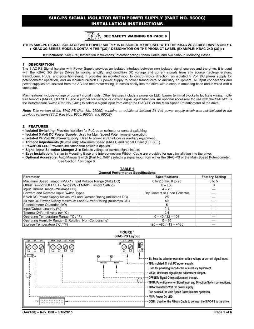
SIAC-PS SIGNAL ISOLATOR WITH POWER SUPPLY (PART NO. 9600C) INSTALLATION INSTRUCTIONS
(A42430) – Rev. B00 – 6/16/2015 Page 1 of 6
SEE SAFETY WARNING ON PAGE 6
THIS SIAC-PS SIGNAL ISOLATOR WITH POWER SUPPLY IS DESIGNED TO BE USED WITH THE KBAC 2G SERIES DRIVES ONLY KBAC 3G SERIES MODELS CONTAIN THE "(3G)" DESIGNATOR ON THE PRODUCT LABEL (EXAMPLE: KBAC-24D (3G))
Kit Includes: SIAC-PS, Installation Instructions, Interconnecting Ribbon Cable, and two Snap-In Mounting Bases.
1 DESCRIPTION The SIAC-PS Signal Isolator with Power Supply provides an isolated interface between non-isolated signal sources and the drive. It is used with the KBAC 2G Series Drives to isolate, amplify, and condition DC voltage and current signals from any source (tach-generators, transducers, PLCs, and potentiometers). It provides an isolated input to control motor direction, an isolated 5 Volt DC power supply for potentiometer operation, and an isolated 24 Volt DC power supply to power transducers or auxiliary equipment. All input connections and power supplies are isolated from the AC line and motor wiring. It installs easily into the drive with a snap-in mounting base and is wired with a connector. Main features include voltage or current signal inputs. Other features include a power on LED, barrier terminal blocks to facilitate wiring, multi-turn trimpots (MAX1, OFFSET), and a jumper for voltage or current signal input selection. An optional accessory for use with the SIAC-PS is the Auto/Manual Switch (Part No. 9481) to select a signal input from either the SIAC-PS or the Main Speed Potentiometer of the drive. Note: This version of the SIAC-PS (Part No. 9600C) contains an additional isolated 24 Volt power supply which was not included in the previous versions (SIAC Part Nos. 9600, 9600A, and 9600B). 2 FEATURES Isolated Switching: Provides isolation for PLC open collector or contact switching. Isolated 5 Volt DC Power Supply: Used for Main Speed Potentiometer operation. Isolated 24 Volt DC Power Supply: Used to power a transducer or auxiliary equipment. Trimpot Adjustments (Multi-Turn): Maximum Speed (MAX1) and Signal Offset (OFFSET). Power On LED: Provides indication that power is applied. Signal Input Selection (Jumper J1): Selects voltage or current signal inputs. Easy Installation: A snap-in Mounting Base and Interconnecting Ribbon Cable are provided for easy installation into the drive. Optional Accessory: Auto/Manual Switch (Part No. 9481) selects a signal input from either the SIAC-PS or the Main Speed Potentiometer. See Section 7 on page 6.
TABLE 1 General Performance Specifications
Parameter Specifications Factory Setting Maximum Speed Trimpot (MAX1) Input Voltage Range (Volts DC) 0 to 2.5 thru 0 to 25 0 to 5 Offset Trimpot (OFFSET) Range (% of MAX1 Trimpot Setting) 0 – ±50 0 Input Current Range (milliamps DC) 4 – 20 — Forward and Reverse Input Switch Types Dry Contact or Open Collector — 5 Volt DC Power Supply Maximum Load Current Rating (milliamps DC) 25 — 24 Volt DC Power Supply Maximum Load Current Rating (milliamps DC) 50 — Potentiometer Operation (kΩ) 5 — Input/Output Linearity (%) 0.1 — Thermal Drift (millivolts per °C) 0.4 — Operating Temperature Range (°C / °F) 0 – 40 / 32 – 104 — Operating Humidity Range (% Relative, Non-Condensing) 0 – 95 — Storage Temperature (°C / °F) -25 – +85 / -13 – +185 —
FIGURE 1
SIAC-PS Layout
SIAC-PS SIGNAL ISOLATOR WITH POWER SUPPLY (PART NO. 9600C) INSTALLATION INSTRUCTIONS
(A42430) – Rev. B00 – 6/16/2015 Page 2 of 6
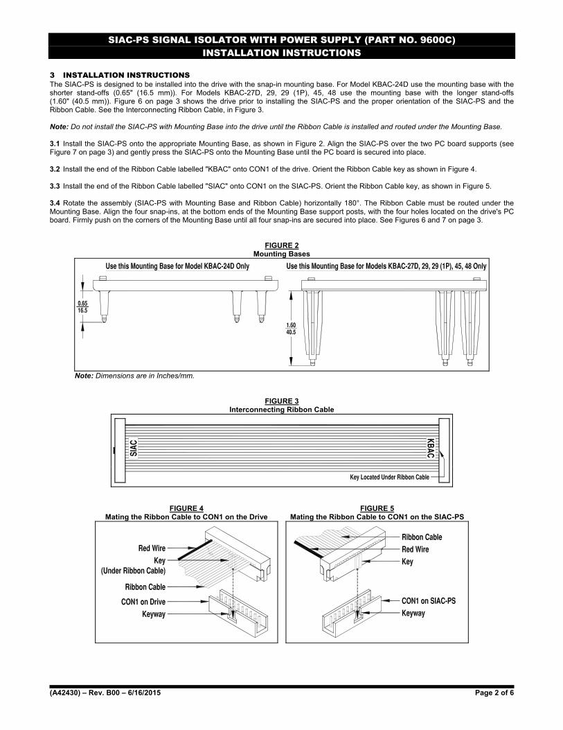
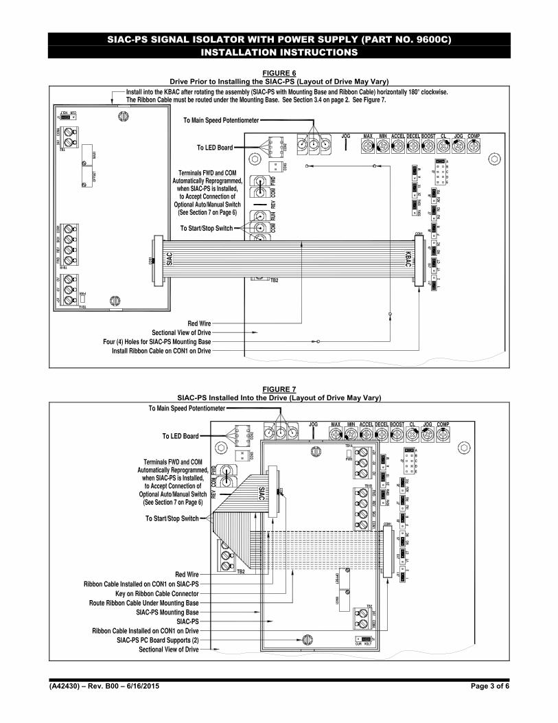
3 INSTALLATION INSTRUCTIONS The SIAC-PS is designed to be installed into the drive with the snap-in mounting base. For Model KBAC-24D use the mounting base with the shorter stand-offs (0.65" (16.5 mm)). For Models KBAC-27D, 29, 29 (1P), 45, 48 use the mounting base with the longer stand-offs (1.60" (40.5 mm)). Figure 6 on page 3 shows the drive prior to installing the SIAC-PS and the proper orientation of the SIAC-PS and the Ribbon Cable. See the Interconnecting Ribbon Cable, in Figure 3. Note: Do not install the SIAC-PS with Mounting Base into the drive until the Ribbon Cable is installed and routed under the Mounting Base. 3.1 Install the SIAC-PS onto the appropriate Mounting Base, as shown in Figure 2. Align the SIAC-PS over the two PC board supports (see Figure 7 on page 3) and gently press the SIAC-PS onto the Mounting Base until the PC board is secured into place. 3.2 Install the end of the Ribbon Cable labelled "KBAC" onto CON1 of the drive. Orient the Ribbon Cable key as shown in Figure 4. 3.3 Install the end of the Ribbon Cable labelled "SIAC" onto CON1 on the SIAC-PS. Orient the Ribbon Cable key, as shown in Figure 5. 3.4 Rotate the assembly (SIAC-PS with Mounting Base and Ribbon Cable) horizontally 180°. The Ribbon Cable must be routed under the Mounting Base. Align the four snap-ins, at the bottom ends of the Mounting Base support posts, with the four holes located on the drive's PC board. Firmly push on the corners of the Mounting Base until all four snap-ins are secured into place. See Figures 6 and 7 on page 3.
FIGURE 2 Mounting Bases
Note: Dimensions are in Inches/mm.
FIGURE 3 Interconnecting Ribbon Cable
FIGURE 4 Mating the Ribbon Cable to CON1 on the Drive
FIGURE 5 Mating the Ribbon Cable to CON1 on the SIAC-PS
SIAC-PS SIGNAL ISOLATOR WITH POWER SUPPLY (PART NO. 9600C) INSTALLATION INSTRUCTIONS
(A42430) – Rev. B00 – 6/16/2015 Page 3 of 6
FIGURE 6 Drive Prior to Installing the SIAC-PS (Layout of Drive May Vary)
FIGURE 7 SIAC-PS Installed Into the Drive (Layout of Drive May Vary)

SIAC-PS SIGNAL ISOLATOR WITH POWER SUPPLY (PART NO. 9600C) INSTALLATION INSTRUCTIONS
(A42430) – Rev. B00 – 6/16/2015 Page 4 of 6
4 WIRING INSTRUCTIONS All connections are made on Terminal Blocks TB1A, TB1B, and TB2 on the SIAC-PS. See Table 2 for wiring information.
WARNING! Disconnect the main power before making connections to the drive.
TABLE 2 Terminal Blocks TB1A, TB1B, and TB2 Wiring Information
Maximum Wire Size (Cu) Recommended Tightening Torque AWG mm2 in-lbs kg-cm
16 1.3 3.5 4 4.1 Voltage Following Connection: A 0 to 2.5 thru 0 to 25 Volt DC analog signal input can be used to control motor speed. Factory setting is 0 to 5 Volts DC. The drive output will linearly follow the analog signal input. Wire the signal input positive lead (+) to Terminal "SIG1" and the negative lead (-) to Terminal "COM1". For Forward Speed Operation, wire a jumper between Terminals "0V" and "FWD". For Reverse Speed Operation wire a jumper between Terminals "0V" and "REV". Set Jumper J1 to the "VOLT" position (factory setting). See Figure 9 on page 5. Note: Use the MAX1 Trimpot on the SIAC-PS to scale the signal input, as described in Section 5.1. Do not use the MAX Trimpot on the drive when the SIAC-PS is installed. 4.2 Current Following Connection: A 4 – 20 mA DC analog signal input can be used to control motor speed. The drive output will linearly follow the analog signal input. Wire the signal input positive lead (+) to Terminal "SIG1" and the negative lead (-) to Terminal "COM1". For Forward Speed Operation, wire a jumper (not supplied) between Terminals "0V" and "FWD". For Reverse Speed Operation wire a jumper (not supplied) between Terminals "0V" and "REV". Set Jumper J1 to the "CUR" position. See Figure 10 on page 5. Note: The MIN Trimpot on the drive is not functional when the SIAC-PS is installed. Use the OFFSET Trimpot on the SIAC-PS to offset the signal input, as described in Section 5.2. 4.3 Unidirectional Main Speed Potentiometer with Forward-Stop-Reverse Switch Connections: A 5 kΩ potentiometer (not supplied) can be used to control motor speed. Wire the potentiometer high side to Terminal "+5V", the wiper to Terminal "SIG1", and the low side to Terminal "COM1". For selection of motor direction, wire a Forward-Stop-Reverse Switch to Terminals "0V", "FWD", and "REV". See Application Note in Section 4.4. See Figure 11 on page 5. 4.4 Form "C" Contact or Relay Forward-Stop-Reverse Connection: A form "C" contact or relay can be used to select motor direction. Wire the circuit to Terminals "0V", "FWD", and "REV". See Figure 12 on page 5. Application Note: If using the SIAC-PS in conjunction with the Forward-Stop-Reverse Switch (Part No. 9480), the Forward-Stop-Reverse Switch must be connected to the SIAC-PS instead of the KBAC. Cut off all three insulated straight terminals from the end of the Forward-Stop-Reverse Switch wires. Strip the wires 1/4". Connect the white/green wire to Terminal 0V on TB1A, connect the white/yellow wire to Terminal FWD on TB1B, and connect the white/red wire to Terminal REV on TB1B. 4.5 Open Collector Forward-Stop-Reverse Connection: An open collector circuit can be used to select motor direction. Wire the circuit to Terminals "0V", "FWD", and "REV". See Figure 13 on page 5. 4.6 Transducer or Auxiliary Equipment Connection: The 24 Volt DC Power supply can be used to power a transducer or auxiliary equipment. The maximum current rating is 50 mA DC. See Figure 14 on page 5. 4.7 Optional Auto/Manual Switch (Part No. 9481): See Section 7 on page 6. 5 TRIMPOT ADJUSTMENTS The SIAC-PS contains trimpots which are factory set for most applications. The SIAC-PS is factory set for Voltage Following Operation to run the motor from zero speed to full speed with a 0 to 5 Volt DC analog signal input. For Current Following Operation, see Section 5.2. Some applications may require readjustment of the trimpots in order to tailor the drive for a specific application. 5.1 Maximum Speed Trimpot (MAX1): The MAX1 Trimpot is factory set to run the motor at full speed with a 5 Volt DC analog signal input. For a higher analog signal input (25 Volt DC maximum), rotate the MAX1 Trimpot counterclockwise. For a lower analog signal input (2.5 Volt DC min.), rotate the MAX1 Trimpot clockwise. See Figure 8. Note: The MAX Trimpot on the drive has been factory set to an Upper Frequency Limit of 60 Hz (50 Hz, for 50 Hz motors). If the application requires a slightly higher maximum frequency (up to 66 Hz), rotate the MAX Trimpot on the drive to full clockwise position. 5.2 Signal Offset (OFFSET): The OFFSET Trimpot is used to recalibrate the drive for Current Following Operation. The SIAC-PS will run the motor from zero speed to full speed with a 4 – 20 mA DC analog signal input. For a higher minimum speed setting, rotate the OFFSET trimpot clockwise. For a lower minimum speed setting, rotate the OFFSET Trimpot counterclockwise. See Figure 8. Note: The MIN Trimpot on the drive is not functional when the SIAC-PS is installed.
FIGURE 8 Trimpot Adjustments
+
+
SIAC-PS SIGNAL ISOLATOR WITH POWER SUPPLY (PART NO. 9600C) INSTALLATION INSTRUCTIONS
(A42430) – Rev. B00 – 6/16/2015 Page 5 of 6
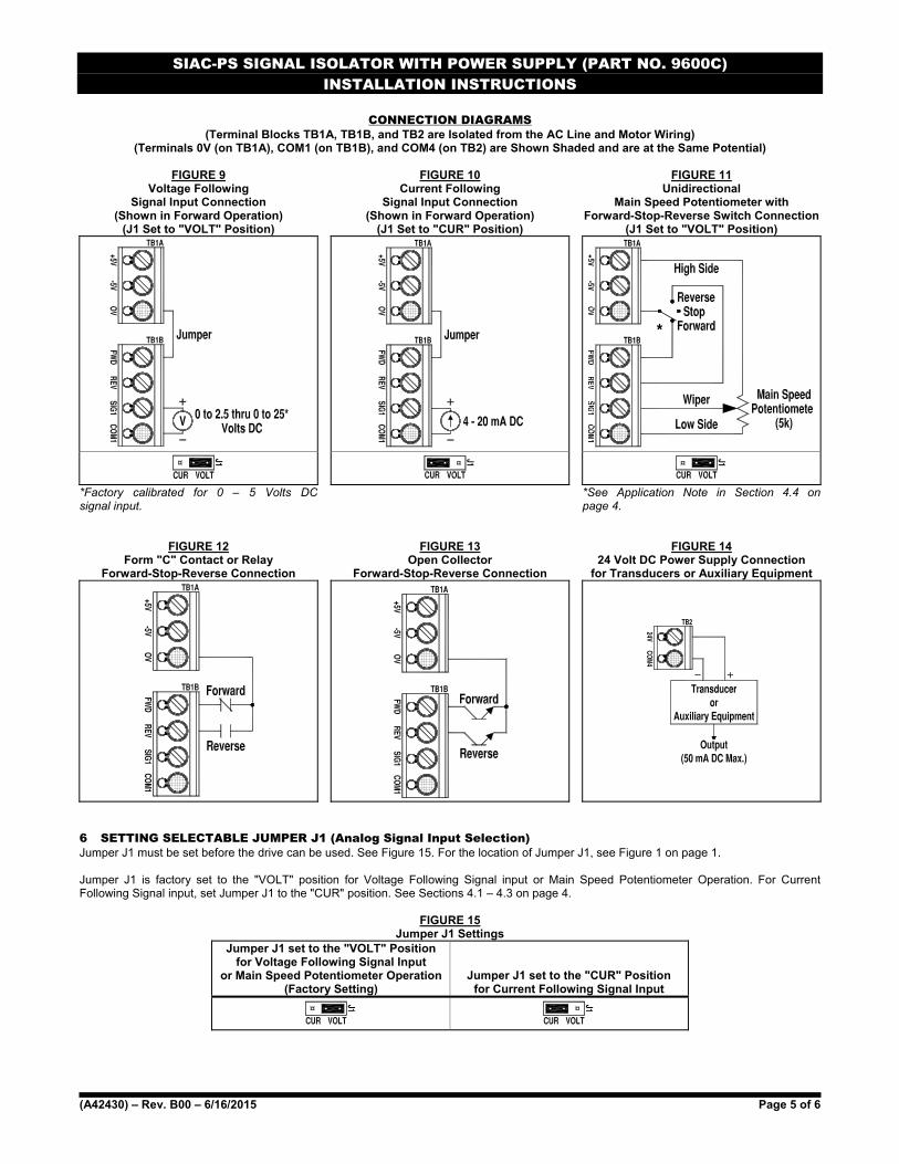
CONNECTION DIAGRAMS (Terminal Blocks TB1A, TB1B, and TB2 are Isolated from the AC Line and Motor Wiring)
(Terminals 0V (on TB1A), COM1 (on TB1B), and COM4 (on TB2) are Shown Shaded and are at the Same Potential)
FIGURE 9 Voltage Following
Signal Input Connection (Shown in Forward Operation)
(J1 Set to "VOLT" Position)
FIGURE 10 Current Following
Signal Input Connection (Shown in Forward Operation)
(J1 Set to "CUR" Position)
FIGURE 11 Unidirectional
Main Speed Potentiometer with Forward-Stop-Reverse Switch Connection
(J1 Set to "VOLT" Position)
*
*Factory calibrated for 0 – 5 Volts DC signal input.
*See Application Note in Section 4.4 on page 4.
FIGURE 12 Form "C" Contact or Relay
Forward-Stop-Reverse Connection
FIGURE 13 Open Collector
Forward-Stop-Reverse Connection
FIGURE 14 24 Volt DC Power Supply Connection
for Transducers or Auxiliary Equipment
6 SETTING SELECTABLE JUMPER J1 (Analog Signal Input Selection) Jumper J1 must be set before the drive can be used. See Figure 15. For the location of Jumper J1, see Figure 1 on page 1. Jumper J1 is factory set to the "VOLT" position for Voltage Following Signal input or Main Speed Potentiometer Operation. For Current Following Signal input, set Jumper J1 to the "CUR" position. See Sections 4.1 – 4.3 on page 4.
FIGURE 15 Jumper J1 Settings
Jumper J1 set to the "VOLT" Position for Voltage Following Signal Input
or Main Speed Potentiometer Operation (Factory Setting)
Jumper J1 set to the "CUR" Position for Current Following Signal Input
SIAC-PS SIGNAL ISOLATOR WITH POWER SUPPLY (PART NO. 9600C) INSTALLATION INSTRUCTIONS
(A42430) – Rev. B00 – 6/16/2015 Page 6 of 6
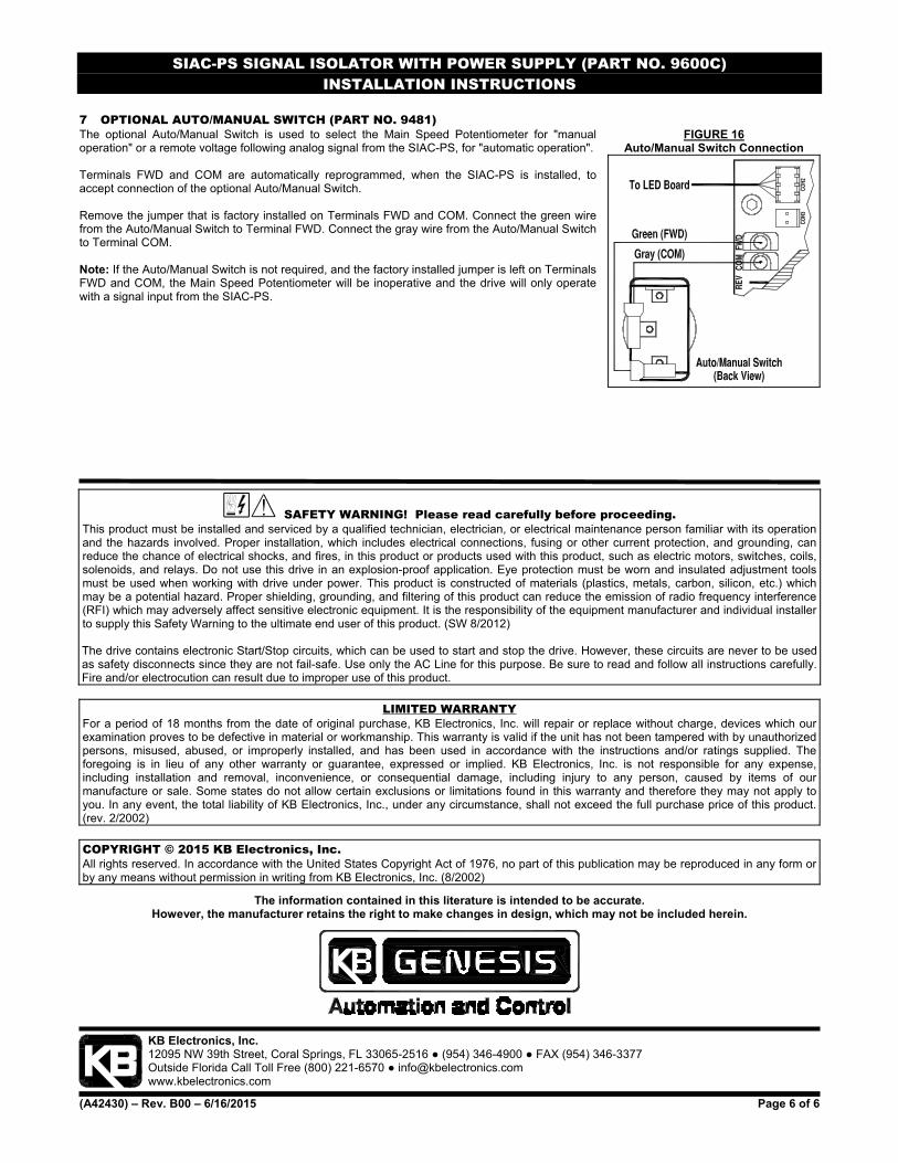
7 OPTIONAL AUTO/MANUAL SWITCH (PART NO. 9481) The optional Auto/Manual Switch is used to select the Main Speed Potentiometer for "manual operation" or a remote voltage following analog signal from the SIAC-PS, for "automatic operation". Terminals FWD and COM are automatically reprogrammed, when the SIAC-PS is installed, to accept connection of the optional Auto/Manual Switch. Remove the jumper that is factory installed on Terminals FWD and COM. Connect the green wire from the Auto/Manual Switch to Terminal FWD. Connect the gray wire from the Auto/Manual Switch to Terminal COM. Note: If the Auto/Manual Switch is not required, and the factory installed jumper is left on Terminals FWD and COM, the Main Speed Potentiometer will be inoperative and the drive will only operate with a signal input from the SIAC-PS.
SAFETY WARNING! Please read carefully before proceeding. This product must be installed and serviced by a qualified technician, electrician, or electrical maintenance person familiar with its operation and the hazards involved. Proper installation, which includes electrical connections, fusing or other current protection, and grounding, can reduce the chance of electrical shocks, and fires, in this product or products used with this product, such as electric motors, switches, coils, solenoids, and relays. Do not use this drive in an explosion-proof application. Eye protection must be worn and insulated adjustment tools must be used when working with drive under power. This product is constructed of materials (plastics, metals, carbon, silicon, etc.) which may be a potential hazard. Proper shielding, grounding, and filtering of this product can reduce the emission of radio frequency interference (RFI) which may adversely affect sensitive electronic equipment. It is the responsibility of the equipment manufacturer and individual installer to supply this Safety Warning to the ultimate end user of this product. (SW 8/2012) The drive contains electronic Start/Stop circuits, which can be used to start and stop the drive. However, these circuits are never to be used as safety disconnects since they are not fail-safe. Use only the AC Line for this purpose. Be sure to read and follow all instructions carefully. Fire and/or electrocution can result due to improper use of this product.
LIMITED WARRANTY For a period of 18 months from the date of original purchase, KB Electronics, Inc. will repair or replace without charge, devices which our examination proves to be defective in material or workmanship. This warranty is valid if the unit has not been tampered with by unauthorized persons, misused, abused, or improperly installed, and has been used in accordance with the instructions and/or ratings supplied. The foregoing is in lieu of any other warranty or guarantee, expressed or implied. KB Electronics, Inc. is not responsible for any expense, including installation and removal, inconvenience, or consequential damage, including injury to any person, caused by items of our manufacture or sale. Some states do not allow certain exclusions or limitations found in this warranty and therefore they may not apply to you. In any event, the total liability of KB Electronics, Inc., under any circumstance, shall not exceed the full purchase price of this product.(rev. 2/2002)
COPYRIGHT © 2015 KB Electronics, Inc. All rights reserved. In accordance with the United States Copyright Act of 1976, no part of this publication may be reproduced in any form or by any means without permission in writing from KB Electronics, Inc. (8/2002)
The information contained in this literature is intended to be accurate. However, the manufacturer retains the right to make changes in design, which may not be included herein.
KB Electronics, Inc. 12095 NW 39th Street, Coral Springs, FL 33065-2516 (954) 346-4900 FAX (954) 346-3377 Outside Florida Call Toll Free (800) 221-6570 [email protected] www.kbelectronics.com
FIGURE 16 Auto/Manual Switch Connection