Embed Size (px)
DESCRIPTION
Water Softener Manual
Citation preview
IMPORTANT: Fill in pertinent information on page 2 for future reference.
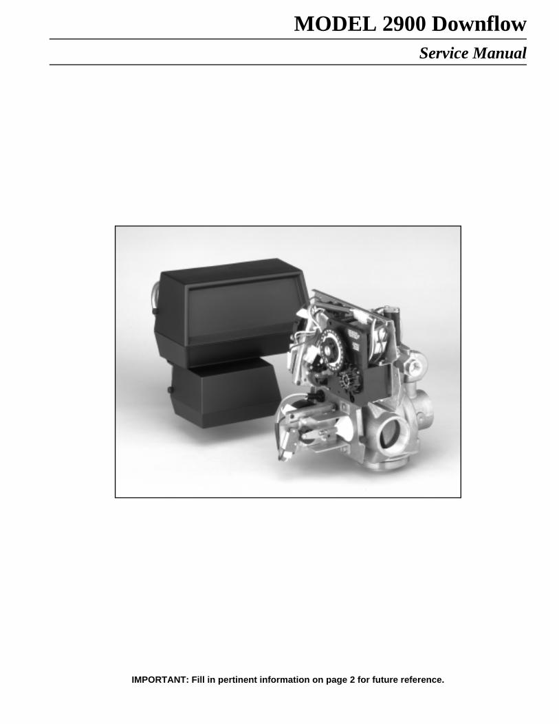
MODEL 2900 DownflowService Manual
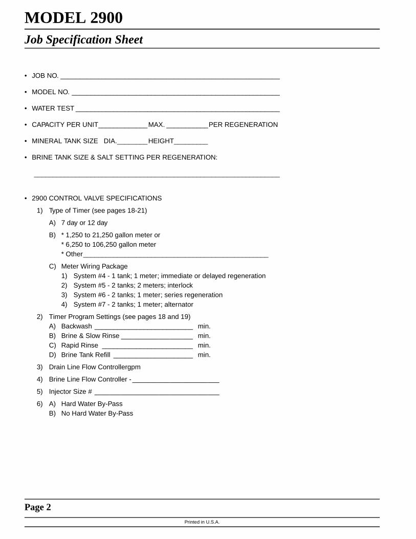
MODEL 2900Job Specification Sheet
Printed in U.S.A.
• JOB NO. __________________________________________________________
• MODEL NO. _______________________________________________________
• WATER TEST ______________________________________________________
• CAPACITY PER UNIT_____________MAX. ___________PER REGENERATION
• MINERAL TANK SIZE DIA.________HEIGHT _________
• BRINE TANK SIZE & SALT SETTING PER REGENERATION:
_________________________________________________________________
Page 2
• 2900 CONTROL VALVE SPECIFICATIONS
1) Type of Timer (see pages 18-21)
A) 7 day or 12 day
B) * 1,250 to 21,250 gallon meter or* 6,250 to 106,250 gallon meter* Other_________________________________________________
C) Meter Wiring Package1) System #4 - 1 tank; 1 meter; immediate or delayed regeneration2) System #5 - 2 tanks; 2 meters; interlock3) System #6 - 2 tanks; 1 meter; series regeneration4) System #7 - 2 tanks; 1 meter; alternator
2) Timer Program Settings (see pages 18 and 19)A) Backwash __________________________ min.B) Brine & Slow Rinse ___________________ min.C) Rapid Rinse ________________________ min.D) Brine Tank Refill _____________________ min.
3) Drain Line Flow Controllergpm
4) Brine Line Flow Controller - _______________________
5) Injector Size # _________________________________
6) A) Hard Water By-PassB) No Hard Water By-Pass

Printed in U.S.A.
Page 3
MODEL 2900General Commercial Pre-Installation Check List
WATER PRESSURE: A minimum of 25 pounds of water pressure is required for regeneration valve to operateeffectively.
ELECTRICAL FACILITIES: A continuous 110 volt, 60 Hertz current supply is required. Make certain the current supplyis always hot and cannot be turned off with another switch.
EXISTING PLUMBING: Condition of existing plumbing should be free from lime and iron buildup. Piping that is built upheavily with lime and/or iron should be replaced. If piping is clogged with iron, a separate iron filter unit should beinstalled ahead of the water softener.
LOCATION OF SOFTENER AND DRAIN: The softener should be located close to a drain.
BY-PASS VALVES: Always provide for the installation of a by-pass valve.
CAUTION: Water pressure is not to exceed 120 p.s.i., water temperature is not to exceed 100° F, and the unit cannotbe subjected to freezing conditions.
Installation Instructions
1. Place the softener tank where you want to install the unit making sure the unit is level and on a firm base.(Maximum 4 feet apart for twin units.)
2. All plumbing should be done in accordance with local plumbing codes. The pipe size for the drain line should be thesame size as the drain line flow control female connection. Water meters are to be installed on soft water outlets.Twin units with (1) one meter shall be installed on common soft water outlet of units.
3. Solder joints near the drain must be done prior to connecting the Drain Line Flow Control fitting. Leave at least 6”between the DLFC and solder joints when soldering when the pipes are connected on the DLFC. Failure to do thiscould cause interior damage to the DLFC.
4. Teflon tape is the only sealant to be used on the drain fitting. The drain from twin units may be run through acommon line.
5. Make sure that the floor is clean beneath the salt storage tank and that it is level.
6. Place approximately 1″ of water above the grid plate (if used) in your salt tank. Salt may be placed in the unit at thistime.
7. On units with a by-pass, place in by-pass position. Turn on the main water supply. Open a cold soft water tapnearby and let run a few minutes or until the system is free from foreign material (usually solder) that may haveresulted from the installation.
8. Place the by-pass in service position.
9. Manually index the softener control into “service” position and let water flow into the mineral tank. When water flowstops, open a cold water tap nearby and let run until air pressure is relieved.
10. Electrical: All electrical connections must be connected according to codes. Use electrical conduit if applicable.Remote meter systems and Twin meter system wiring diagrams are on pages 26-29.
11. Plug into power supply.

Printed in U.S.A.
Page 4
MODEL 2900
Hard water enters unit at valve inlet and flows down thru the mineral in the mineral tank.Conditioned water enters center tube thru the bottom distributor — then flows up thru thecenter tube — around the piston and out the side outlet of the valve.
Hard water enters unit at valve inlet — flows thru service adapterfor by pass, and up thru coupling to regenerating valve inlet Itthen flows thru the regenerating valve piston — down the centertube — thru the bottom distributor and up thru the mineral —around the piston and out the drain line. If optional no hard waterby pass piston is used water flow to outlet is prevented by anextended section of the service piston which closes the outletport from by pass water until the end of rapid rinse.
Hard water enters unit at valve inlet — flows up into injectorhousing and down thru nozzle and orifice to draw brine fromthe brine tank — brine flows down thru mineral and enters thecenter tube thru bottom distributor — flows up thru center tube— around the piston and out thru the drain line.
1
3
SERVICE POSITION
BACKWASH POSITION BRINE POSITION2
BRINE VALVE
FLOW CONTROL
INLET
OUTLET
BRINETANK
RESINTANK
INLET
DRAIN
OPTION:NO HARD WATER BY PASSBRINE VALVE
FLOWCONTROL
DRAIN
INLET
OUTLET
INLET
BRINETANK
RESINTANK
BRINE VALVE
FLOW CONTROL
INLET
OUTLET
BRINETANK
DRAIN
INLET
RESINTANK
Printed in U.S.A.
Page 5
MODEL 2900
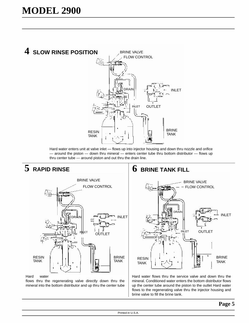
4
6
SLOW RINSE POSITION
BRINE TANK FILL5 RAPID RINSE
Hard water enters unit at valve inlet — flows up into injector housing and down thru nozzle and orifice— around the piston — down thru mineral — enters center tube thru bottom distributor — flows upthru center tube — around piston and out thru the drain line.
Hard waterflows thru the regenerating valve directly down thru themineral into the bottom distributor and up thru the center tube
Hard water flows thru the service valve and down thru themineral. Conditioned water enters the bottom distributor flowsup the center tube around the piston to the outlet Hard waterflows to the regenerating valve thru the injector housing andbrine valve to fill the brine tank.
BRINE VALVEFLOW CONTROL
DRAIN
OUTLET
INLET
BRINETANK
INLET
RESINTANK
BRINE VALVE
FLOW CONTROL
INLET
OUTLET
DRAIN
INLET
BRINETANK
RESINTANK
BRINE VALVEFLOW CONTROL
INLET
OUTLET
BRINETANK
RESINTANK
DRAIN
INLET

Printed in U.S.A.
Page 6
MODEL 2900Control Drive Assembly
(See opposite page for parts list)
1
23
4
56 7
8
9
10
11
12
1516 17
18
19
20
21
22
2324
2526 27
28
29
33
34
35
36
33
Printed in U.S.A.
Page 7
MODEL 2900Control Drive Assembly
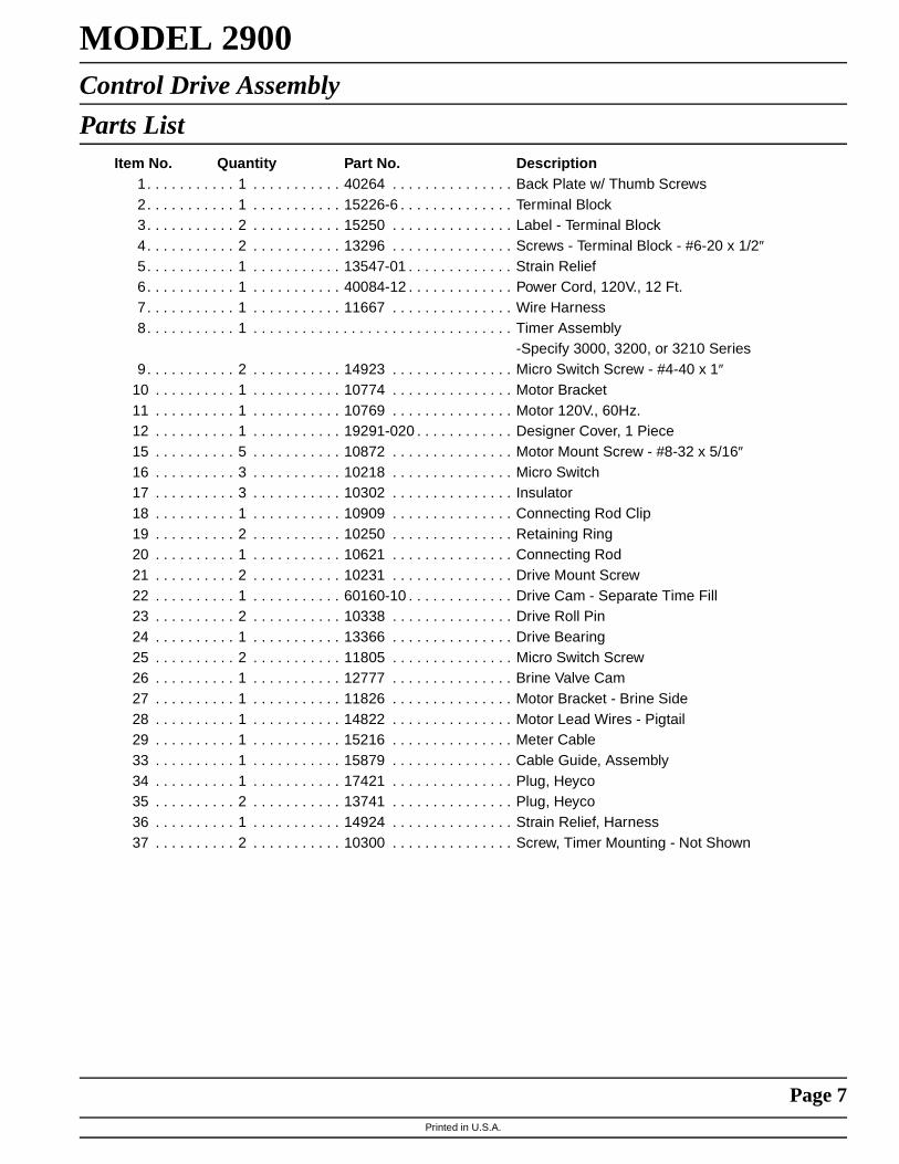
Parts ListItem No. Quantity Part No. Description
1. . . . . . . . . . . 1 . . . . . . . . . . . 40264 . . . . . . . . . . . . . . . Back Plate w/ Thumb Screws2. . . . . . . . . . . 1 . . . . . . . . . . . 15226-6 . . . . . . . . . . . . . . Terminal Block3. . . . . . . . . . . 2 . . . . . . . . . . . 15250 . . . . . . . . . . . . . . . Label - Terminal Block4. . . . . . . . . . . 2 . . . . . . . . . . . 13296 . . . . . . . . . . . . . . . Screws - Terminal Block - #6-20 x 1/2″5. . . . . . . . . . . 1 . . . . . . . . . . . 13547-01 . . . . . . . . . . . . . Strain Relief6. . . . . . . . . . . 1 . . . . . . . . . . . 40084-12 . . . . . . . . . . . . . Power Cord, 120V., 12 Ft. 7. . . . . . . . . . . 1 . . . . . . . . . . . 11667 . . . . . . . . . . . . . . . Wire Harness8. . . . . . . . . . . 1 . . . . . . . . . . . . . . . . . . . . . . . . . . . . . . . . Timer Assembly
-Specify 3000, 3200, or 3210 Series9. . . . . . . . . . . 2 . . . . . . . . . . . 14923 . . . . . . . . . . . . . . . Micro Switch Screw - #4-40 x 1″
10 . . . . . . . . . . 1 . . . . . . . . . . . 10774 . . . . . . . . . . . . . . . Motor Bracket11 . . . . . . . . . . 1 . . . . . . . . . . . 10769 . . . . . . . . . . . . . . . Motor 120V., 60Hz.12 . . . . . . . . . . 1 . . . . . . . . . . . 19291-020 . . . . . . . . . . . . Designer Cover, 1 Piece15 . . . . . . . . . . 5 . . . . . . . . . . . 10872 . . . . . . . . . . . . . . . Motor Mount Screw - #8-32 x 5/16″16 . . . . . . . . . . 3 . . . . . . . . . . . 10218 . . . . . . . . . . . . . . . Micro Switch17 . . . . . . . . . . 3 . . . . . . . . . . . 10302 . . . . . . . . . . . . . . . Insulator18 . . . . . . . . . . 1 . . . . . . . . . . . 10909 . . . . . . . . . . . . . . . Connecting Rod Clip19 . . . . . . . . . . 2 . . . . . . . . . . . 10250 . . . . . . . . . . . . . . . Retaining Ring20 . . . . . . . . . . 1 . . . . . . . . . . . 10621 . . . . . . . . . . . . . . . Connecting Rod 21 . . . . . . . . . . 2 . . . . . . . . . . . 10231 . . . . . . . . . . . . . . . Drive Mount Screw22 . . . . . . . . . . 1 . . . . . . . . . . . 60160-10 . . . . . . . . . . . . . Drive Cam - Separate Time Fill23 . . . . . . . . . . 2 . . . . . . . . . . . 10338 . . . . . . . . . . . . . . . Drive Roll Pin24 . . . . . . . . . . 1 . . . . . . . . . . . 13366 . . . . . . . . . . . . . . . Drive Bearing25 . . . . . . . . . . 2 . . . . . . . . . . . 11805 . . . . . . . . . . . . . . . Micro Switch Screw26 . . . . . . . . . . 1 . . . . . . . . . . . 12777 . . . . . . . . . . . . . . . Brine Valve Cam27 . . . . . . . . . . 1 . . . . . . . . . . . 11826 . . . . . . . . . . . . . . . Motor Bracket - Brine Side28 . . . . . . . . . . 1 . . . . . . . . . . . 14822 . . . . . . . . . . . . . . . Motor Lead Wires - Pigtail29 . . . . . . . . . . 1 . . . . . . . . . . . 15216 . . . . . . . . . . . . . . . Meter Cable33 . . . . . . . . . . 1 . . . . . . . . . . . 15879 . . . . . . . . . . . . . . . Cable Guide, Assembly34 . . . . . . . . . . 1 . . . . . . . . . . . 17421 . . . . . . . . . . . . . . . Plug, Heyco35 . . . . . . . . . . 2 . . . . . . . . . . . 13741 . . . . . . . . . . . . . . . Plug, Heyco36 . . . . . . . . . . 1 . . . . . . . . . . . 14924 . . . . . . . . . . . . . . . Strain Relief, Harness37 . . . . . . . . . . 2 . . . . . . . . . . . 10300 . . . . . . . . . . . . . . . Screw, Timer Mounting - Not Shown

Printed in U.S.A.
Page 8
MODEL 2900Service Assemblies
(See opposite page for parts list)

Printed in U.S.A.
Page 9
MODEL 2900Service Assemblies
Parts ListItem No. Quantity Part No. Description
1. . . . . . . . . . . 1 . . . . . . . . . . . 18697-01 . . . . . . . . . . . . . Back Plate1 . . . . . . . . . . . 18697-13 . . . . . . . . . . . . . Back Plate (19 pin connector)1 . . . . . . . . . . . 18697-14 . . . . . . . . . . . . . Back Plate (9 pin connector)
2. . . . . . . . . . . 1 . . . . . . . . . . . 18748 . . . . . . . . . . . . . . . Plug, .750 Hole3. . . . . . . . . . . 1 . . . . . . . . . . . 18720 . . . . . . . . . . . . . . . Pipe Plug, 1/2-14 NPT4. . . . . . . . . . . 3 . . . . . . . . . . . 18747 . . . . . . . . . . . . . . . Plug, .190 Hole5. . . . . . . . . . . 1 . . . . . . . . . . . 17967 . . . . . . . . . . . . . . . Fitting, Liquid Tight6. . . . . . . . . . . 1 . . . . . . . . . . . 17845-02 . . . . . . . . . . . . . Pin, Hinge7. . . . . . . . . . . 5 . . . . . . . . . . . 10300 . . . . . . . . . . . . . . . Screw8. . . . . . . . . . . 1 . . . . . . . . . . . 18750 . . . . . . . . . . . . . . . Bracket, Terminal9. . . . . . . . . . . 1 . . . . . . . . . . . 15226-X. . . . . . . . . . . . . . Terminal Strip (X denote number of terminals)
10 . . . . . . . . . . 2 . . . . . . . . . . . 10299 . . . . . . . . . . . . . . . Screw, Terminal Strip11 . . . . . . . . . . 2 . . . . . . . . . . . 15250 . . . . . . . . . . . . . . . Label, Terminal Strip12 . . . . . . . . . . 2 . . . . . . . . . . . 12732 . . . . . . . . . . . . . . . Nut, Terminal Strip13 . . . . . . . . . . 1 . . . . . . . . . . . 17831-01 . . . . . . . . . . . . . Holder, Battery, 9V14 . . . . . . . . . . 1 . . . . . . . . . . . 18716-01 . . . . . . . . . . . . . Seal, Cover15 . . . . . . . . . . 4 . . . . . . . . . . . 19203 . . . . . . . . . . . . . . . Screw, Window16 . . . . . . . . . . 1 . . . . . . . . . . . 18745 . . . . . . . . . . . . . . . Window17 . . . . . . . . . . 1 . . . . . . . . . . . 18615-02 . . . . . . . . . . . . . Seal, Window18 . . . . . . . . . . 1 . . . . . . . . . . . 18670-02 . . . . . . . . . . . . . Cover, Hinged, Black
1 . . . . . . . . . . . 18670-07 . . . . . . . . . . . . . Cover, Hinged, Blue19 . . . . . . . . . . 1 . . . . . . . . . . . 18744 . . . . . . . . . . . . . . . Screw, Cover20 . . . . . . . . . . 5 . . . . . . . . . . . 10872 . . . . . . . . . . . . . . . Screw, Motor21 . . . . . . . . . . 1 . . . . . . . . . . . 60150-10 . . . . . . . . . . . . . Cam, Drive STF22 . . . . . . . . . . 1 . . . . . . . . . . . 10909 . . . . . . . . . . . . . . . Pin, Cam23 . . . . . . . . . . 2 . . . . . . . . . . . 14923 . . . . . . . . . . . . . . . Screw, Switch24 . . . . . . . . . . 4 . . . . . . . . . . . 10302 . . . . . . . . . . . . . . . Insulator25 3 . . . . . . . . . . . 10218 . . . . . . . . . . . . . . . Micro Switch26 . . . . . . . . . . 2 . . . . . . . . . . . 10231 . . . . . . . . . . . . . . . Screw, Motor Bracket27 . . . . . . . . . . 1 . . . . . . . . . . . 10774 . . . . . . . . . . . . . . . Bracket, Motor28 . . . . . . . . . . 1 . . . . . . . . . . . 10769 . . . . . . . . . . . . . . . Motor, 110V 60 Hz
1 . . . . . . . . . . . 12292 . . . . . . . . . . . . . . . Motor, 230V 50/60 Hz1 . . . . . . . . . . . 13383 . . . . . . . . . . . . . . . Motor, 24V 50 Hz1 . . . . . . . . . . . 15073 . . . . . . . . . . . . . . . Motor, 24V 60 Hz
29 . . . . . . . . . . 1 . . . . . . . . . . . 11826 . . . . . . . . . . . . . . . Bracket, Motor30 . . . . . . . . . . 1 . . . . . . . . . . . 12777 . . . . . . . . . . . . . . . Cam, Brine Valve31 . . . . . . . . . . 2 . . . . . . . . . . . 10338 . . . . . . . . . . . . . . . Pin, Roll32 . . . . . . . . . . 2 . . . . . . . . . . . 11805 . . . . . . . . . . . . . . . Screw, Switch33 . . . . . . . . . . 1 . . . . . . . . . . . 11667 . . . . . . . . . . . . . . . Wire Harness, Drive Motor (Systems 4, 5 & 6)34 . . . . . . . . . . 1 . . . . . . . . . . . 14822 . . . . . . . . . . . . . . . Wire Harness, Upper Drive (Systems 4, 5 & 6)35 . . . . . . . . . . 1 . . . . . . . . . . . 15926 . . . . . . . . . . . . . . . Wire Harness, Lower Drive (System 4)36 . . . . . . . . . . 1 . . . . . . . . . . . 14827 . . . . . . . . . . . . . . . Wire Harness, Lower Drive (Systems 5 & 6)37 . . . . . . . . . . 1 . . . . . . . . . . . 16564 . . . . . . . . . . . . . . . Wire Harness, Upper Drive (System 7)38 . . . . . . . . . . 1 . . . . . . . . . . . 15938 . . . . . . . . . . . . . . . Wire Harness, Lower, Lead Valve (System 7)39 . . . . . . . . . . 1 . . . . . . . . . . . 15936 . . . . . . . . . . . . . . . Wire Harness, Lower, Lag Valve (System 7)40 . . . . . . . . . . 1 . . . . . . . . . . . 19009 . . . . . . . . . . . . . . . Cable, Interlock, 9 Pin Connector (Systems 5, 6, 7)41 . . . . . . . . . . 1 . . . . . . . . . . . 19010 . . . . . . . . . . . . . . . Receptacle, Interlock, 9 Pin Connector
(Systems 5, 6 & 7)

Printed in U.S.A.
Page 10
MODEL 2900Adapter Control Drive
(See opposite page for parts list)
1
2
3
45
6
7
8
9
10
11
12
13
14
15
16
17
18

Printed in U.S.A.
Page 11
MODEL 2900Adapter Control Drive
Parts List
Item No. Quantity Part No. Description1. . . . . . . . . . . 1 . . . . . . . . . . . 14770 . . . . . . . . . . . . . . . Back Plate2. . . . . . . . . . . 1 . . . . . . . . . . . 14769 . . . . . . . . . . . . . . . Motor Bracket3. . . . . . . . . . . 1 . . . . . . . . . . . 14772 . . . . . . . . . . . . . . . Motor - 110V.,60Hz.4. . . . . . . . . . . 4 . . . . . . . . . . . 10872 . . . . . . . . . . . . . . . Screw - Motor Mtg.S. . . . . . . . . . . 1 . . . . . . . . . . . 14784 . . . . . . . . . . . . . . . Connecting Rod Bearing6. . . . . . . . . . . 1 . . . . . . . . . . . 14775 . . . . . . . . . . . . . . . Drive Cam7. . . . . . . . . . . 1 . . . . . . . . . . . 14759 . . . . . . . . . . . . . . . Piston Drive Link8. . . . . . . . . . . 1 . . . . . . . . . . . 10250 . . . . . . . . . . . . . . . Retaining Ring9. . . . . . . . . . . 1 . . . . . . . . . . . 11381 . . . . . . . . . . . . . . . Pin Drive Cam Mtg.
10 . . . . . . . . . . 1 . . . . . . . . . . . 14813 . . . . . . . . . . . . . . . Spring Clip11 . . . . . . . . . . 1 . . . . . . . . . . . 10218 . . . . . . . . . . . . . . . Micro Switch - System 4
2 . . . . . . . . . . . 10218 . . . . . . . . . . . . . . . Micro Switch - Systems 5, 6, 712 . . . . . . . . . . 2 . . . . . . . . . . . 10302 . . . . . . . . . . . . . . . Insulator - System 4
3 . . . . . . . . . . . 11805 . . . . . . . . . . . . . . . Insulator - Systems 5, 6, 713 . . . . . . . . . . 2 . . . . . . . . . . . 19849 . . . . . . . . . . . . . . . Screw - Micro Switch - System 4
2 . . . . . . . . . . . 14923 . . . . . . . . . . . . . . . Screw - Micro Switch - Systems 5, 6, 714 . . . . . . . . . . 2 . . . . . . . . . . . 11224 . . . . . . . . . . . . . . . Screw - Drive Mounting15 . . . . . . . . . . 1 . . . . . . . . . . . 15926 . . . . . . . . . . . . . . . Wire Harness #4
1 . . . . . . . . . . . 14827 . . . . . . . . . . . . . . . Wire Harness #5 & #61 . . . . . . . . . . . 15938 . . . . . . . . . . . . . . . Wire Harness #7 - Lead Valve1 . . . . . . . . . . . 15936 . . . . . . . . . . . . . . . Wire Harness #7 - Lag Valve
16 . . . . . . . . . . 1 . . . . . . . . . . . 14924 . . . . . . . . . . . . . . . Strain Relief17 . . . . . . . . . . 1 . . . . . . . . . . . 14800 . . . . . . . . . . . . . . . Cover18 . . . . . . . . . . 2 . . . . . . . . . . . 15236 . . . . . . . . . . . . . . . Screw Assy. - Cover
NOTE: For System 7 Lead Only, Add
1 . . . . . . . . . . . 10218 . . . . . . . . . . . . . . . Micro Switch (Not Shown)2 . . . . . . . . . . . 10302 . . . . . . . . . . . . . . . Insulator (Not Shown)2 . . . . . . . . . . . 11805 . . . . . . . . . . . . . . . Mtg. Screw (Not Shown)1 . . . . . . . . . . . 1S713 . . . . . . . . . . . . . . . Mtg. Plate (Not Shown)1 . . . . . . . . . . . 16103 . . . . . . . . . . . . . . . Insulator (Not Shown)

Printed in U.S.A.
Page 12
MODEL 2900Lower Environmental Control Drive
(See opposite page for parts list)
1
2
3
4
5
67
8 9
10
11
12
1314
15
16
17
18
19
2021
22
23
24
2526
27
28
29

Printed in U.S.A.
Page 13
MODEL 2900Lower Environmental Control Drive
Parts ListItem No. Quantity Part No. Description
1. . . . . . . . . . . 1 . . . . . . . . . . . 18693 . . . . . . . . . . . . . . . Conduit, Interdrive
2. . . . . . . . . . . 2 . . . . . . . . . . . 18692 . . . . . . . . . . . . . . . Washer, Sealing
3. . . . . . . . . . . 2 . . . . . . . . . . . 18691 . . . . . . . . . . . . . . . Connector, Conduit
4. . . . . . . . . . . 1 . . . . . . . . . . . 18709 . . . . . . . . . . . . . . . Back Plate, Lower
5. . . . . . . . . . . 1 . . . . . . . . . . . 14769 . . . . . . . . . . . . . . . Bracket, Motor
6. . . . . . . . . . . 4 . . . . . . . . . . . 10872 . . . . . . . . . . . . . . . Screw, Motor
7. . . . . . . . . . . 1 . . . . . . . . . . . 18746 . . . . . . . . . . . . . . . Bearing, Connecting Rod
8. . . . . . . . . . . 1 . . . . . . . . . . . 18726 . . . . . . . . . . . . . . . Spacer, Indicator
9. . . . . . . . . . . 1 . . . . . . . . . . . 14775 . . . . . . . . . . . . . . . Cam, Drive
10 . . . . . . . . . . 1 . . . . . . . . . . . 14759 . . . . . . . . . . . . . . . Link, Piston Rod
11 . . . . . . . . . . 1 . . . . . . . . . . . 14813 . . . . . . . . . . . . . . . Pin, Spring
12 . . . . . . . . . . 1 . . . . . . . . . . . 10250 . . . . . . . . . . . . . . . Retaining Ring
13 . . . . . . . . . . 1 . . . . . . . . . . . 18727 . . . . . . . . . . . . . . . Washer, Curved Spring
14 . . . . . . . . . . 1 . . . . . . . . . . . 15742 . . . . . . . . . . . . . . . Screw, Indicator
15 . . . . . . . . . . 1 . . . . . . . . . . . 18725 . . . . . . . . . . . . . . . Indicator, Off Line / Service / On Line
16 . . . . . . . . . . 2 . . . . . . . . . . . 11805 . . . . . . . . . . . . . . . Screw, Switch, System 4
2 . . . . . . . . . . . 14923 . . . . . . . . . . . . . . . Screw, Switch, Systems 5, 6 & 7
17 . . . . . . . . . . 2 . . . . . . . . . . . 10302 . . . . . . . . . . . . . . . Insulator Switch, System 4
3 . . . . . . . . . . . 14923 . . . . . . . . . . . . . . . Screw, Switch, Systems 5, 6 & 7
18 . . . . . . . . . . 1 . . . . . . . . . . . 10218 . . . . . . . . . . . . . . . Micro Switch, System 4
2 . . . . . . . . . . . 10218 . . . . . . . . . . . . . . . Micro Switch, Systems 5, 6 & 7
19 . . . . . . . . . . 1 . . . . . . . . . . . 11381 . . . . . . . . . . . . . . . Pin, Cam
20 . . . . . . . . . . 2 . . . . . . . . . . . 11224 . . . . . . . . . . . . . . . Screw, Motor Bracket
21 . . . . . . . . . . 1 . . . . . . . . . . . 10872 . . . . . . . . . . . . . . . Screw, Spacer
22 . . . . . . . . . . 1 . . . . . . . . . . . 14772 . . . . . . . . . . . . . . . Motor, 110V 50/60 Hz
1 . . . . . . . . . . . 15305 . . . . . . . . . . . . . . . Motor, 220V 50/60 Hz
1 . . . . . . . . . . . 15651 . . . . . . . . . . . . . . . Motor, 24V 50 Hz
1 . . . . . . . . . . . 15653 . . . . . . . . . . . . . . . Motor, 24V 60 Hz
23 . . . . . . . . . . 1 . . . . . . . . . . . 19015 . . . . . . . . . . . . . . . Wire Harness, System 4
1 . . . . . . . . . . . 19016 . . . . . . . . . . . . . . . Wire Harness, Systems 5 & 6
1 . . . . . . . . . . . 19017 . . . . . . . . . . . . . . . Wire Harness, System 7, Lead Valve
1 . . . . . . . . . . . 19018 . . . . . . . . . . . . . . . Wire Harness, System 7, Lag Valve
24 . . . . . . . . . . 2 . . . . . . . . . . . 14430 . . . . . . . . . . . . . . . Screw, Window
25 . . . . . . . . . . 1 . . . . . . . . . . . 18724 . . . . . . . . . . . . . . . Window
26 . . . . . . . . . . 1 . . . . . . . . . . . 18615-03 . . . . . . . . . . . . . Seal, Window
27 . . . . . . . . . . 1 . . . . . . . . . . . 18716-02 . . . . . . . . . . . . . Seal, Cover
28 . . . . . . . . . . 1 . . . . . . . . . . . 18708-02 . . . . . . . . . . . . . Cover, Lower, Black
1 . . . . . . . . . . . 18708-07 . . . . . . . . . . . . . Cover, Lower, Blue
29 . . . . . . . . . . 2 . . . . . . . . . . . 18744 . . . . . . . . . . . . . . . Screw, Cover

Printed in U.S.A.
Page 14
MODEL 29001700 Brine System
12
34
56
78
910
1112
13
14
15
16
17
18
19
2021
16
15
14
2021
Printed in U.S.A.
Page 15
MODEL 29001700 Brine System
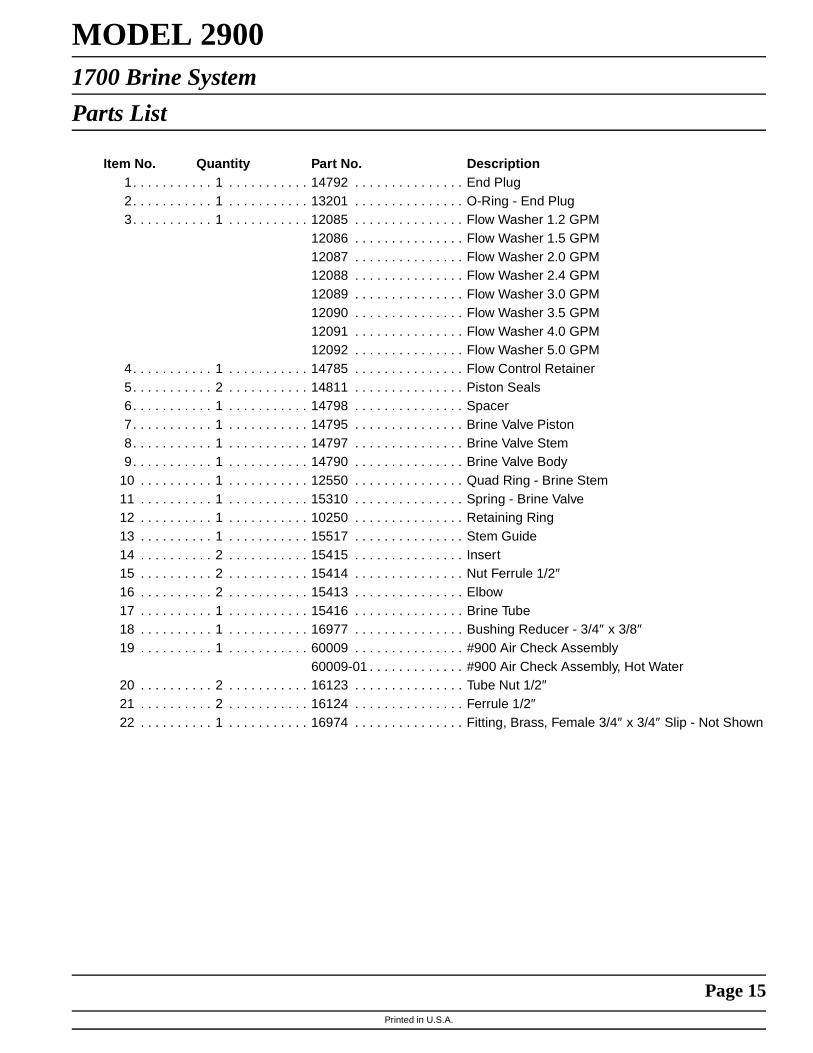
Parts List
Item No. Quantity Part No. Description1. . . . . . . . . . . 1 . . . . . . . . . . . 14792 . . . . . . . . . . . . . . . End Plug2. . . . . . . . . . . 1 . . . . . . . . . . . 13201 . . . . . . . . . . . . . . . O-Ring - End Plug3. . . . . . . . . . . 1 . . . . . . . . . . . 12085 . . . . . . . . . . . . . . . Flow Washer 1.2 GPM
12086 . . . . . . . . . . . . . . . Flow Washer 1.5 GPM12087 . . . . . . . . . . . . . . . Flow Washer 2.0 GPM12088 . . . . . . . . . . . . . . . Flow Washer 2.4 GPM12089 . . . . . . . . . . . . . . . Flow Washer 3.0 GPM12090 . . . . . . . . . . . . . . . Flow Washer 3.5 GPM12091 . . . . . . . . . . . . . . . Flow Washer 4.0 GPM12092 . . . . . . . . . . . . . . . Flow Washer 5.0 GPM
4. . . . . . . . . . . 1 . . . . . . . . . . . 14785 . . . . . . . . . . . . . . . Flow Control Retainer5. . . . . . . . . . . 2 . . . . . . . . . . . 14811 . . . . . . . . . . . . . . . Piston Seals6. . . . . . . . . . . 1 . . . . . . . . . . . 14798 . . . . . . . . . . . . . . . Spacer7. . . . . . . . . . . 1 . . . . . . . . . . . 14795 . . . . . . . . . . . . . . . Brine Valve Piston8. . . . . . . . . . . 1 . . . . . . . . . . . 14797 . . . . . . . . . . . . . . . Brine Valve Stem9. . . . . . . . . . . 1 . . . . . . . . . . . 14790 . . . . . . . . . . . . . . . Brine Valve Body
10 . . . . . . . . . . 1 . . . . . . . . . . . 12550 . . . . . . . . . . . . . . . Quad Ring - Brine Stem11 . . . . . . . . . . 1 . . . . . . . . . . . 15310 . . . . . . . . . . . . . . . Spring - Brine Valve12 . . . . . . . . . . 1 . . . . . . . . . . . 10250 . . . . . . . . . . . . . . . Retaining Ring13 . . . . . . . . . . 1 . . . . . . . . . . . 15517 . . . . . . . . . . . . . . . Stem Guide14 . . . . . . . . . . 2 . . . . . . . . . . . 15415 . . . . . . . . . . . . . . . Insert15 . . . . . . . . . . 2 . . . . . . . . . . . 15414 . . . . . . . . . . . . . . . Nut Ferrule 1/2″16 . . . . . . . . . . 2 . . . . . . . . . . . 15413 . . . . . . . . . . . . . . . Elbow17 . . . . . . . . . . 1 . . . . . . . . . . . 15416 . . . . . . . . . . . . . . . Brine Tube18 . . . . . . . . . . 1 . . . . . . . . . . . 16977 . . . . . . . . . . . . . . . Bushing Reducer - 3/4″ x 3/8″19 . . . . . . . . . . 1 . . . . . . . . . . . 60009 . . . . . . . . . . . . . . . #900 Air Check Assembly
60009-01 . . . . . . . . . . . . . #900 Air Check Assembly, Hot Water20 . . . . . . . . . . 2 . . . . . . . . . . . 16123 . . . . . . . . . . . . . . . Tube Nut 1/2″21 . . . . . . . . . . 2 . . . . . . . . . . . 16124 . . . . . . . . . . . . . . . Ferrule 1/2″22 . . . . . . . . . . 1 . . . . . . . . . . . 16974 . . . . . . . . . . . . . . . Fitting, Brass, Female 3/4″ x 3/4″ Slip - Not Shown

Printed in U.S.A.
Page 16
MODEL 2900Control Valve
(See opposite page for parts list)
Printed in U.S.A.
Page 17
MODEL 2900Control Valve
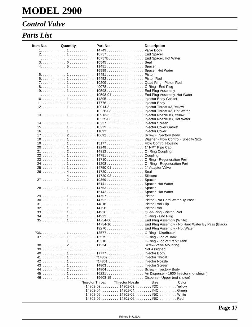
Parts ListItem No. Quantity Part No. Description
1. . . . . . . . . . . . . 1 . . . . . . . . . . . . . .14749 . . . . . . . . . . . . . . . . . . . Valve Body2. . . . . . . . . . . . . 1 . . . . . . . . . . . . . .10757 . . . . . . . . . . . . . . . . . . . End Spacer
. . . . . . . . . . . . . . . . . . . . . . . . . . . .10757B . . . . . . . . . . . . . . . . . . End Spacer, Hot Water3. . . . . . . . . . . . . 6 . . . . . . . . . . . . . .10545 . . . . . . . . . . . . . . . . . . . Seal4. . . . . . . . . . . . . 5 . . . . . . . . . . . . . .11451 . . . . . . . . . . . . . . . . . . . Spacer
16589 . . . . . . . . . . . . . . . . . . . Spacer, Hot Water5. . . . . . . . . . . . . 1 . . . . . . . . . . . . . .14451 . . . . . . . . . . . . . . . . . . . Piston6. . . . . . . . . . . . . 1 . . . . . . . . . . . . . .14452 . . . . . . . . . . . . . . . . . . . Piston Rod7. . . . . . . . . . . . . 1 . . . . . . . . . . . . . .10209 . . . . . . . . . . . . . . . . . . . Quad Ring - Piston Rod8. . . . . . . . . . . . . 1 . . . . . . . . . . . . . .40078 . . . . . . . . . . . . . . . . . . . O-Ring - End Plug9. . . . . . . . . . . . . 1 . . . . . . . . . . . . . .10598 . . . . . . . . . . . . . . . . . . . End Plug Assembly
. . . . . . . . . . . . . . . . . . . . . . . . . . . .10598-01 . . . . . . . . . . . . . . . . End Plug Assembly, Hot Water10 . . . . . . . . . . . . 1 . . . . . . . . . . . . . .14805 . . . . . . . . . . . . . . . . . . . Injector Body Gasket11 . . . . . . . . . . . . 1 . . . . . . . . . . . . . .17776 . . . . . . . . . . . . . . . . . . . Injector Body12 . . . . . . . . . . . . 1 . . . . . . . . . . . . . .10914-3 . . . . . . . . . . . . . . . . . Injector Throat #3, Yellow
10226-03 . . . . . . . . . . . . . . . . Injector Throat #3, Hot Water13 . . . . . . . . . . . . 1 . . . . . . . . . . . . . .10913-3 . . . . . . . . . . . . . . . . . Injector Nozzle #3, Yellow
10225-03 . . . . . . . . . . . . . . . . Injector Nozzle #3, Hot Water14 . . . . . . . . . . . . 1 . . . . . . . . . . . . . .10227 . . . . . . . . . . . . . . . . . . . Injector Screen15 . . . . . . . . . . . . 1 . . . . . . . . . . . . . .10229 . . . . . . . . . . . . . . . . . . . Injector Cover Gasket16 . . . . . . . . . . . . 1 . . . . . . . . . . . . . .11893 . . . . . . . . . . . . . . . . . . . Injector Cover17 . . . . . . . . . . . . 2 . . . . . . . . . . . . . .10692 . . . . . . . . . . . . . . . . . . . Screw - Injectory Body18 . . . . . . . . . . . . 1 . . . . . . . . . . . . . . . . . . . . . . . . . . . . . . . . . . . . . . . Washer - Flow Control - Specify Size19 . . . . . . . . . . . . 1 . . . . . . . . . . . . . .15177 . . . . . . . . . . . . . . . . . . . Flow Control Housing20 . . . . . . . . . . . . 1 . . . . . . . . . . . . . .12248 . . . . . . . . . . . . . . . . . . . 1″ NPT Pipe Cap21 . . . . . . . . . . . . 2 . . . . . . . . . . . . . .14812 . . . . . . . . . . . . . . . . . . . O- Ring Coupling22 . . . . . . . . . . . . 1 . . . . . . . . . . . . . .14751 . . . . . . . . . . . . . . . . . . . Coupling23 . . . . . . . . . . . . 1 . . . . . . . . . . . . . .11710 . . . . . . . . . . . . . . . . . . . O-Ring - Regeneration Port24 . . . . . . . . . . . . 1 . . . . . . . . . . . . . .11208 . . . . . . . . . . . . . . . . . . . O- Ring - Regeneration Port25 . . . . . . . . . . . . 1 . . . . . . . . . . . . . .14750-01 . . . . . . . . . . . . . . . . 2″ Adapter Valve26 . . . . . . . . . . . . 4 . . . . . . . . . . . . . .11720 . . . . . . . . . . . . . . . . . . . Seal
4 . . . . . . . . . . . . . .11720-02 . . . . . . . . . . . . . . . . Silicone27 . . . . . . . . . . . . 2 . . . . . . . . . . . . . .10369 . . . . . . . . . . . . . . . . . . . Spacer
16141 . . . . . . . . . . . . . . . . . . . Spacer, Hot Water28 . . . . . . . . . . . . 1 . . . . . . . . . . . . . .14753 . . . . . . . . . . . . . . . . . . . Spacer
16142 . . . . . . . . . . . . . . . . . . . Spacer, Hot Water29 . . . . . . . . . . . . 1 . . . . . . . . . . . . . .14757 . . . . . . . . . . . . . . . . . . . Piston30 . . . . . . . . . . . . 1 . . . . . . . . . . . . . .14752 . . . . . . . . . . . . . . . . . . . Piston - No Hard Water By Pass31 . . . . . . . . . . . . 1 . . . . . . . . . . . . . .14818 . . . . . . . . . . . . . . . . . . . Piston Rod Clip32 . . . . . . . . . . . . 1 . . . . . . . . . . . . . .14758 . . . . . . . . . . . . . . . . . . . Piston Rod33 . . . . . . . . . . . . 1 . . . . . . . . . . . . . .14926 . . . . . . . . . . . . . . . . . . . Quad-Ring - Piston Rod34 . . . . . . . . . . . . 1 . . . . . . . . . . . . . .14922 . . . . . . . . . . . . . . . . . . . O-Ring - End Plug35 . . . . . . . . . . . . 1 . . . . . . . . . . . . . .14754-00 . . . . . . . . . . . . . . . . End Plug Assembly (White)
14754-10 . . . . . . . . . . . . . . . . End Plug Assembly - No Hard Water By Pass (Black)19276 . . . . . . . . . . . . . . . . . . . End Plug Assembly - Hot Water
*36. . . . . . . . . . . . . 1 . . . . . . . . . . . . . .13577 . . . . . . . . . . . . . . . . . . . O-Ring - Distributor37 . . . . . . . . . . . . 1 . . . . . . . . . . . . . .13575 . . . . . . . . . . . . . . . . . . . O-Ring - Top of Tank
1 . . . . . . . . . . . . . .15210 . . . . . . . . . . . . . . . . . . . O-Ring - Top of “Park” Tank38 . . . . . . . . . . . . 2 . . . . . . . . . . . . . .11224 . . . . . . . . . . . . . . . . . . . Screw-Valve Mounting39 . . . . . . . . . . . . . . . . . . . . . . . . . . . . . . . . . . . . . . . . . . . . . . . . . . . . Not Assigned40 . . . . . . . . . . . . 1 . . . . . . . . . . . . . .17777 . . . . . . . . . . . . . . . . . . . Injector Body41 . . . . . . . . . . . . 1 . . . . . . . . . . . . . .*14802 . . . . . . . . . . . . . . . . . . Injector Throat42 . . . . . . . . . . . . 1 . . . . . . . . . . . . . .*14801 . . . . . . . . . . . . . . . . . . Injector Nozzle43 . . . . . . . . . . . . 1 . . . . . . . . . . . . . .14803 . . . . . . . . . . . . . . . . . . . Injector Screen44 . . . . . . . . . . . . 2 . . . . . . . . . . . . . .14804 . . . . . . . . . . . . . . . . . . . Screw - Injectory Body45 . . . . . . . . . . . . 1 . . . . . . . . . . . . . .16221 . . . . . . . . . . . . . . . . . . . Air Disperser - 1600 Injector (not shown)46 . . . . . . . . . . . . 1 . . . . . . . . . . . . . .19608-15 . . . . . . . . . . . . . . . . Disperser, Upper (not shown)
*Injector Throat *Injector Nozzle Size Color14802-03 . . . . . . . . . 14801-03. . . . . . . . . #3C . . . . . . . . . Yellow14802-04 . . . . . . . . . 14801-04. . . . . . . . . #4C . . . . . . . . . Green14802-05 . . . . . . . . . 14801-05. . . . . . . . . #5C . . . . . . . . . White14802-06 . . . . . . . . . 14801-06. . . . . . . . . #6C . . . . . . . . . Red

Printed in U.S.A.
Page 18
MODEL 2900Control Valve
Side Mount Adapter
Item No. Quantity Part No. Description1 . . . . . . . . . . . 1 . . . . . . . . . . . 14750-01 . . . . . . . . . . . . . 2” Adaptor Valve
*2. . . . . . . . . . . 1 . . . . . . . . . . . 13577 . . . . . . . . . . . . . . . O-Ring - Distributor3 . . . . . . . . . . . 1 . . . . . . . . . . . 13575 . . . . . . . . . . . . . . . O-Ring - Top of Tank
1 . . . . . . . . . . . 15210 . . . . . . . . . . . . . . . O-Ring - Top of “Park” Tank4 . . . . . . . . . . . 1 . . . . . . . . . . . 40316 . . . . . . . . . . . . . . . Adaptor, Side Mount5 . . . . . . . . . . . 1 . . . . . . . . . . . 40372 . . . . . . . . . . . . . . . O-Ring - 1426 . . . . . . . . . . . 1 . . . . . . . . . . . 40368 . . . . . . . . . . . . . . . O-Ring - 1607 . . . . . . . . . . . 1 . . . . . . . . . . . 40310 . . . . . . . . . . . . . . . Base, Rotating8 . . . . . . . . . . . 7 . . . . . . . . . . . 40375 . . . . . . . . . . . . . . . Washer9 . . . . . . . . . . . 7 . . . . . . . . . . . 19768 . . . . . . . . . . . . . . . Screw
*Do not use this O-Ring if control is side mounted.

Printed in U.S.A.
Page 19
MODEL 29001600 Series Brine System
Item No. Quantity Part No. Description1. . . . . . . . . . . . 1 . . . . . . . . . . . . . 10328. . . . . . . . . . . . . . . . . . 90° Elbow - ¼ Pipe Thd. to 3/8″ Tube2. . . . . . . . . . . . 1 . . . . . . . . . . . . . 12767. . . . . . . . . . . . . . . . . . Brine Line Screen3. . . . . . . . . . . . 2 . . . . . . . . . . . . . 10332. . . . . . . . . . . . . . . . . . Insert Sleeve 3/8″ Tube)4. . . . . . . . . . . . 3 . . . . . . . . . . . . . 10329. . . . . . . . . . . . . . . . . . Fitting Nut (3/8″ Tube)5. . . . . . . . . . . . 3 . . . . . . . . . . . . . 10330. . . . . . . . . . . . . . . . . . Derlin Sleeve (3/8″ Tube)6. . . . . . . . . . . . 1 . . . . . . . . . . . . . 15221. . . . . . . . . . . . . . . . . . Brine Valve Tube7. . . . . . . . . . . . 1 . . . . . . . . . . . . . 60002. . . . . . . . . . . . . . . . . . #500 Air Check Assembly
60003. . . . . . . . . . . . . . . . . . #500 Air Check Assembly, Hot Water8. . . . . . . . . . . . 1 . . . . . . . . . . . . . 12794. . . . . . . . . . . . . . . . . . 90° Elbow - 3/8″ Tube to 3/8″ Tube9. . . . . . . . . . . . 1 . . . . . . . . . . . . . Not Supplied . . . . . . . . . . . . Brine Line Tube (3/8″ Flexible Tube)
10 . . . . . . . . . . . 1 . . . . . . . . . . . . . 10250. . . . . . . . . . . . . . . . . . Retaining Ring11 . . . . . . . . . . . 1 . . . . . . . . . . . . . 11749. . . . . . . . . . . . . . . . . . Stem Guide12 . . . . . . . . . . . . . . . . . . . . . . . . . . . . . . . . . . . . . . . . . . . . . . . . Not Assigned13 . . . . . . . . . . . . . . . . . . . . . . . . . . . . . . . . . . . . . . . . . . . . . . . . Not Assigned14 . . . . . . . . . . . 1 . . . . . . . . . . . . . 10249. . . . . . . . . . . . . . . . . . Brine Valve Spring15 . . . . . . . . . . . 1 . . . . . . . . . . . . . 12550. . . . . . . . . . . . . . . . . . Quad Ring16 . . . . . . . . . . . 1 . . . . . . . . . . . . . 12748. . . . . . . . . . . . . . . . . . Brine Valve Body17 . . . . . . . . . . . 1 . . . . . . . . . . . . . 12552. . . . . . . . . . . . . . . . . . Brine Valve Stem18 . . . . . . . . . . . 1 . . . . . . . . . . . . . 12626. . . . . . . . . . . . . . . . . . Brine Valve Seat19 . . . . . . . . . . . 1 . . . . . . . . . . . . . 11982. . . . . . . . . . . . . . . . . . O-Ring20 . . . . . . . . . . . 1 . . . . . . . . . . . . . 60020-25 . . . . . . . . . . . . . . . BLFC.25GPM
60020-50 . . . . . . . . . . . . . . . BLFC .50 GPM60020-100 . . . . . . . . . . . . . . BLFC 1.0 GPM
1 2
3
4
5
6
7
89
10
11
1415
1617
1819
20
5
5
4
4
3

Printed in U.S.A.
Page 20
MODEL 29002″ Meter Assembly
Item No. Quantity Part No. Description1 . . . . . . . . . . . 1. . . . . . . . . . . . 14456. . . . . . . . . . . . . . . . Meter Body2 . . . . . . . . . . . 1. . . . . . . . . . . . 15532. . . . . . . . . . . . . . . . Impeller Shaft Retainer3 . . . . . . . . . . . 1. . . . . . . . . . . . 15432. . . . . . . . . . . . . . . . Impeller Shaft4 . . . . . . . . . . . . . . . . . . . . . . . . . . . . . . . . . . . . . . . . . . . . . Not Assigned5 . . . . . . . . . . . 1. . . . . . . . . . . . 15374. . . . . . . . . . . . . . . . Impeller6 . . . . . . . . . . . 1. . . . . . . . . . . . 13847. . . . . . . . . . . . . . . . O-Ring - Meter Cover
7A . . . . . . . . . . 1. . . . . . . . . . . . 15218. . . . . . . . . . . . . . . . Meter Cover Assembly (Standard)7B . . . . . . . . . . 1. . . . . . . . . . . . 15237. . . . . . . . . . . . . . . . Meter Cover Assembly (Extended Range)8 . . . . . . . . . . . 4. . . . . . . . . . . . 12112. . . . . . . . . . . . . . . . Screw - Meter Cover9 . . . . . . . . . . . 1. . . . . . . . . . . . 14679. . . . . . . . . . . . . . . . O-Ring - Quick Connect
10. . . . . . . . . . . 1. . . . . . . . . . . . 14568. . . . . . . . . . . . . . . . Nipple - Quick Connect11. . . . . . . . . . . 1. . . . . . . . . . . . 14680. . . . . . . . . . . . . . . . Flow Straightener12. . . . . . . . . . . 1. . . . . . . . . . . . 14569. . . . . . . . . . . . . . . . Nut - Quick Connect
1
2
3
5
6
7A
8
9
10
11
12
7B

Printed in U.S.A.
Page 21
MODEL 2900Notes:

Printed in U.S.A.
Page 22
MODEL 2900 ECONOMINDER
Timer Assembly
(See opposite page for parts list)
1
38
2
35
6
7
37
89
107
11
1213
14 15
16
2627
28
2931
3233
34
35
36
623
24
25
1819
20

Printed in U.S.A.
Page 23
MODEL 2900 ECONOMINDER
Timer Assembly
Parts ListItem No. Quantity Part No. Description
1. . . . . . . . . . . 1 . . . . . . . . . . . 13870-01 . . . . . . . . . . . . . Timer Housing Assembly2. . . . . . . . . . . 1 . . . . . . . . . . . 13802 . . . . . . . . . . . . . . . Cycle Actuator Gear3. . . . . . . . . . . 1 . . . . . . . . . . . 40096-24 . . . . . . . . . . . . . 24 Hour Gear Assembly, 12 Midnight
40096-02 . . . . . . . . . . . . . 24 Hour Gear Assembly, 2 A.M.5. . . . . . . . . . . 1 . . . . . . . . . . . 13886-01 . . . . . . . . . . . . . Knob6. . . . . . . . . . . 4 . . . . . . . . . . . 13296 . . . . . . . . . . . . . . . Screw - Timer Knob & Motor Plate Mtg.7. . . . . . . . . . . 2 . . . . . . . . . . . 11999 . . . . . . . . . . . . . . . Button Decal8. . . . . . . . . . . 1 . . . . . . . . . . . 60405-50 . . . . . . . . . . . . . Program Wheel Assembly, 0-21,0009. . . . . . . . . . . 1 . . . . . . . . . . . 13806 . . . . . . . . . . . . . . . Program Wheel Retainer
10 . . . . . . . . . . 1 . . . . . . . . . . . 13748 . . . . . . . . . . . . . . . Screw - Program Wheel Mtg.11 . . . . . . . . . . 1 . . . . . . . . . . . 14265 . . . . . . . . . . . . . . . Spring Clip12 . . . . . . . . . . 1 . . . . . . . . . . . 15424 . . . . . . . . . . . . . . . Spring-Detent13 . . . . . . . . . . 1 . . . . . . . . . . . 15066 . . . . . . . . . . . . . . . Ball - 1/4 in. dia.14 . . . . . . . . . . 1 . . . . . . . . . . . 13911 . . . . . . . . . . . . . . . Main Drive Gear15 . . . . . . . . . . 1 . . . . . . . . . . . 19210 . . . . . . . . . . . . . . . Program Wheel Assembly16 . . . . . . . . . . 21 . . . . . . . . . . 15493 . . . . . . . . . . . . . . . Roll Pin17 . . . . . . . . . . . . . . . . . . . . . . . . . . . . . . . . . . . . . . . . . . . Not Assigned18 . . . . . . . . . . 1 . . . . . . . . . . . 13018 . . . . . . . . . . . . . . . Idler Shaft19 . . . . . . . . . . 1 . . . . . . . . . . . 13312 . . . . . . . . . . . . . . . Spring - Idler20 . . . . . . . . . . 1 . . . . . . . . . . . 13017 . . . . . . . . . . . . . . . Idler Gear21 . . . . . . . . . . 1 . . . . . . . . . . . 13164 . . . . . . . . . . . . . . . Drive Gear23 . . . . . . . . . . 1 . . . . . . . . . . . 13887 . . . . . . . . . . . . . . . Motor Mounting Plate24 . . . . . . . . . . 1 . . . . . . . . . . . 18743 . . . . . . . . . . . . . . . Motor - 110V., 60 Hz.
19659 . . . . . . . . . . . . . . . Motor - 24V., 60 Hz.25 . . . . . . . . . . 2 . . . . . . . . . . . 13278 . . . . . . . . . . . . . . . Screw - Motor Mounting26 . . . . . . . . . . 1 . . . . . . . . . . . 13830 . . . . . . . . . . . . . . . Drive Pinion - Program Wheel27 . . . . . . . . . . 1 . . . . . . . . . . . 13831 . . . . . . . . . . . . . . . Clutch - Drive Pinion28 . . . . . . . . . . 1 . . . . . . . . . . . 14276 . . . . . . . . . . . . . . . Spring29 . . . . . . . . . . 1 . . . . . . . . . . . 14253 . . . . . . . . . . . . . . . Spring Retainer30 . . . . . . . . . . . . . . . . . . . . . . . . . . . . . . . . . . . . . . . . . . . Not Assigned31 . . . . . . . . . . 3 . . . . . . . . . . . 11384 . . . . . . . . . . . . . . . Screw - Timer Hinge & Ground Wire32 . . . . . . . . . . 1 . . . . . . . . . . . 13881 . . . . . . . . . . . . . . . Hinge Bracket33 . . . . . . . . . . 3 . . . . . . . . . . . 14087 . . . . . . . . . . . . . . . Insulator34 . . . . . . . . . . 1 . . . . . . . . . . . 10896 . . . . . . . . . . . . . . . Switch35 . . . . . . . . . . 1 . . . . . . . . . . . 15320 . . . . . . . . . . . . . . . Switch36 . . . . . . . . . . 2 . . . . . . . . . . . 11413 . . . . . . . . . . . . . . . Screw - Switch Mounting37 . . . . . . . . . . 1 . . . . . . . . . . . 14007 . . . . . . . . . . . . . . . Decal - Time of Day38 . . . . . . . . . . 1 . . . . . . . . . . . 14045 . . . . . . . . . . . . . . . Decal - Instructions39 . . . . . . . . . . 1 . . . . . . . . . . . 13902 . . . . . . . . . . . . . . . Harness - Not Shown40 . . . . . . . . . . 2 . . . . . . . . . . . 12681 . . . . . . . . . . . . . . . Wire Connector - Not Shown41 . . . . . . . . . . 1 . . . . . . . . . . . 15354-01 . . . . . . . . . . . . . Ground Wire - Not Shown42 . . . . . . . . . . 1 . . . . . . . . . . . 15465 . . . . . . . . . . . . . . . Caution Label - Not Shown43 . . . . . . . . . . 1 . . . . . . . . . . . 14198 . . . . . . . . . . . . . . . Capacity Label - Not Shown

Printed in U.S.A.
Page 24
MODEL 2900 ECONOMINDER
2″ Commercial Demand Regeneration Control Timer Settings
Typical Programming Procedure
Calculate the gallon capacity of the system, subtract thenecessary reserve requirement and set the gallonsavailable opposite the small white dot on the programwheel gear. Note, drawing shows 8,750 gallon setting.The capacity (gallons) arrow denotes remaining gallonsexclusive of fixed reserve.
How To Set The Time Of Day:
Press and hold the red button in to disengage the drivegear.
Turn the large gear until the actual time of day is oppositethe time of day pointer.
Release the red button to again engage the drive gear.
How To Manually Regenerate Your Water ConditionerAt Any Time:
Turn the manual regeneration knob clockwise.
This slight movement of the manual regeneration knobengages the program wheel and starts the regenerationprogram.
The black center knob will make one revolution in thefollowing approximately three hours and stop in theposition shown in the drawing.
Even though it takes three hours for this center knob tocomplete one revolution, the regeneration cycle of yourunit might be set for only one half of this time.
In any event, conditioned water may be drawn after rinsewater stops flowing from the water conditioner drain line.
Immediate Regeneration Timers:
These timers do not have a 24 hour gear. Setting thegallons on the program wheel and manual regenerationprocedure are the same as previous instructions.
NOTE:
To set meter capacity rotate manual knob one - 360° revolution to set gallonage.
* Immediate regeneration timers do not have 24 hour gear. No time of day can be set.
* 24 HOUR GEAR
MANUALREGENERATIONKNOB
PROGRAMWHEEL
GALLONS LABELWHITE DOT
RED TIMESET BUTTON
SERVICEPOSITIONINDICATOR

Printed in U.S.A.
Page 25
MODEL 3200 TIMERTimer Setting Procedure
How To Set Days On Which Water Conditioner Is To Regenerate:
Rotate the skipper wheel until the number “1” is at the redpointer. Set the days that regeneration is to occur bysliding tabs on the skipper wheel outward to expose tripfingers. Each tab is one day. Finger at red pointer istonight. Moving clockwise from the red pointer, extend orretract fingers to obtain the desired regenerationschedule.
How To Set The Time Of Day:
Press and hold the red button in to disengage the drivegear.
Turn the large gear until the actual time of day is at thetime of day pointer.
Release the red button to again engage the drive gear.
How To Manually Regenerate Your Water Conditioner At Any Time:
Turn the manual regeneration knob clockwise.
This slight movement of the manual regeneration knobengages the program wheel and starts the regenerationprogram.
The black center knob will make one revolution in thefollowing approximately three hours and stop in theposition shown in the drawing.
Even thought it takes three hours for this center knob tocomplete one revolution, the regeneration cycle of yourunit might be set only one half of this time.
In any event, conditioned water may be drawn after rinsewater stops flowing from the water conditioner drain line.
How to Adjust Regeneration Time:
1. Disconnect the power source.
2. Locate the three screws behind the manual regeneration knob by pushing the red button in and rotating the 24 hour dial until each screw appears in the cut out portion of the manual regeneration knob.
3. Loosen each screw slightly to release the pressure on the time plate from the 24 hour gear.
4. Locate the regeneration time pointer on the inside of the 24 hour dial in the cut out.
5. Turn the time plate so the desired regeneration time aligns next to the raised arrow.
6. Push the red button in and rotate the 24 hour dial. Tighten each of the three screws.
7. Push the red button and locate the pointer one more time to ensure the desired regeneration time is correct.
8. Reset the time of day and restore power to the unit.
3200 ADJUSTABLE REGENERATION TIMER
SERVICEPOSITIONINDICATOR
24 HR. GEARMANUAL REGENERATION KNOB
RED TIMESET BUTTON
SKIPPER WHEEL, 12 DAY(SHOWS EVERY OTHERDAY REGENERATION)

Printed in U.S.A.
Page 26
MODEL 3200 & 3210 TIMER SERIESRegeneration Cycle Program Setting Procedure(Brine Tank Refill Separate From Rapid Rinse)
How To Set The Regeneration Cycle Program:
The regeneration cycle program on your water conditionerhas been factory preset, however, portions of the cycle orprogram may be lengthened or shortened in time to suitlocal conditions.
3200 & 3210 Series Timers (Figure to Right)
To expose cycle program wheel, grasp timer in upper left-hand corner and pull, releasing snap retainer andswinging timer to the right
To change the regeneration cycle program, the programwheel must be removed. Grasp program wheel andsqueeze protruding lugs toward center, lift program wheeloff timer. (Switch arms may require movement to facilitateremoval.)
Return timer to closed position engaging snap retainer inback plate. Make certain all electrical wires locate abovesnap retainer post
Timer Setting Procedure for 3200 & 3210 Timer
How To Change The Length Of The Backwash Time:
The program wheel as shown in the drawing is in theservice position. As you look at the numbered side of theprogram wheel, the group of pins starting at zerodetermines the length of time your unit will backwash.
FOR EXAMPLE: If there are six pins in this section, thetime of backwash will be 12 min. (2 min. per pin). Tochange the length of backwash time, add or remove pinsas required. The number of pins times two equals thebackwash time in minutes.
How To Change The Length Of Brine And Rinse Time:
The group of holes between the last pin in the backwashsection and the second group of pins determines thelength of time that your unit will brine and rinse (2 min. perhole.)
To change the length of brine and rinse time, move therapid rinse group of pins to give more or fewer holes in thebrine and rinse section. Number of holes times twoequals brine and rinse time in minutes.
How To Change The Length Of Rapid Rinse:
The second group of pins on the program wheeldetermines the length of time that your water conditionerwill rapid rinse. (2 min. per pin.)
See Page 27 For Typical Timer Settings
To change the length of rapid rinse time, add or removepins at the higher numbered end of this section asrequired. The number of pins times two equals the rapidrinse time in minutes.
How To Change The Length Of Brine Tank Refill Time:
The second group of holes in the program wheeldetermines the length of time that your water conditionerwill refill the brine tank (2 min. per hole.)
To change the length of refill time, move the two pins atthe end of the second group of holes as required.
The regeneration cycle is complete when the outermicroswitch is tripped by the two pin set at end of thebrine tank refill section.
The program wheel, however, will continue to rotate untilthe inner micro-switch drops into the notch on theprogram wheel.
BRINE & RINSESECTION(2 MIN. PER HOLE)
PIN STORAGE
BACKWASHSECTION(2 MIN. PER PIN)
BRINE TANKREFILLSECTION(2 MIN.PER HOLE)
PROGRAMWHEEL FORCONTROL OFREGENERATIONCYCLE
RAPIDRINSESECTION(2 MIN.PER PIN)

Printed in U.S.A.
Page 27
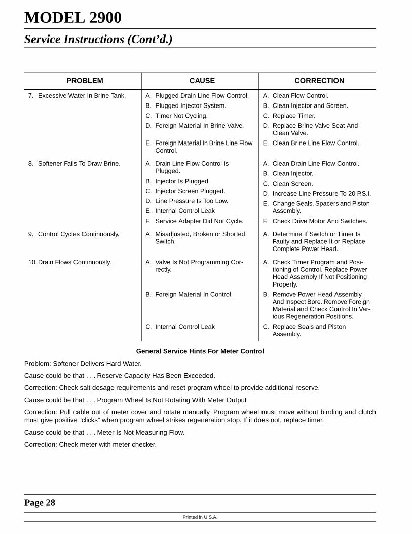
MODEL 2900Service Instructions
PROBLEM CAUSE CORRECTION
1. Softener Fails To Regenerate. A. Electrical Service To Unit Has Been Interrupted.
B. Timer Is Defective.
C. Power Failure.
A. Assure Permanent Electrical Ser-vice (Check Fuse, Plug, Pull Chain or Switch).
B. Replace Timer.
C. Reset Time of Day.
2. Hard Water. A. By-Pass Valve is Open.
B. No Salt in Brine Tank
C. Injector Screen Plugged.
D. Insufficient Water Flowing Into Brine Tank
E. Hot Water Tank Hardness.
F. Leak At Distributor Tube.
G. Internal Valve Leak
H. Service Adapter Did Not Return To Service.
A. Close By-Pass Valve.
B. Add Salt To Brine Tank and Main-tain Salt Level Above Water Level.
C. Clean Injector Screen.
D. Check Brine Tank Fill Time And Clean Brine Line Flow Control If Plugged.
E. Repeated Flushings Of The Hot Water Tank is Required.
F. Make Sure Distributor Tube Is Not Cracked. Check O-Ring And Tube Pilot.
G. Replace Seals and Spacers And/Or Piston.
H. Check Drive Motor And Switch.
3. Unit Used Too Much Salt A. Improper Salt Setting.
B. Excessive Water in Brine Tank
A. Check Salt Usage and Salt Set-ting.
B. See Problem No. 7.
4. Loss Of Water Pressure. A. Iron Buildup In Line To Water Con-ditioner.
B. Iron Buildup in Water Conditioner.
C. Inlet of Control Plugged Due to Foreign Material Broken Loose From Pipes By Recent Work Done On Plumbing System.
A. Clean Line To Water Conditioner.
B. Clean Control and Add Mineral Cleaner to Mineral Bed.
Increased Frequency of Regeneration.
C. Remove Piston and Clean Control.
5. Loss of Mineral Through Drain Line.
A. Air In Water System.
B. Improperly Sized Drain Line Flow Control.
A. Assure That Well System Has Proper Air Eliminator Control. Check For Dry Well Condition.
B. Check For Proper Drain Rate.
6. Iron In Conditioned Water. A. Fouled Mineral Bed. A. Check Backwash, Brine Draw And Brine Tank Fill. Increase Fre-quency of Regeneration. Increase Backwash Time.
Printed in U.S.A.
Page 28
MODEL 2900Service Instructions (Cont’d.)
General Service Hints For Meter Control
Problem: Softener Delivers Hard Water.
Cause could be that . . . Reserve Capacity Has Been Exceeded.
Correction: Check salt dosage requirements and reset program wheel to provide additional reserve.
Cause could be that . . . Program Wheel Is Not Rotating With Meter Output
Correction: Pull cable out of meter cover and rotate manually. Program wheel must move without binding and clutchmust give positive “clicks” when program wheel strikes regeneration stop. If it does not, replace timer.
Cause could be that . . . Meter Is Not Measuring Flow.
Correction: Check meter with meter checker.
7. Excessive Water In Brine Tank. A. Plugged Drain Line Flow Control.
B. Plugged Injector System.
C. Timer Not Cycling.
D. Foreign Material In Brine Valve.
E. Foreign Material In Brine Line Flow Control.
A. Clean Flow Control.
B. Clean Injector and Screen.
C. Replace Timer.
D. Replace Brine Valve Seat And Clean Valve.
E. Clean Brine Line Flow Control.
8. Softener Fails To Draw Brine. A. Drain Line Flow Control Is Plugged.
B. Injector Is Plugged.
C. Injector Screen Plugged.
D. Line Pressure Is Too Low.
E. Internal Control Leak
F. Service Adapter Did Not Cycle.
A. Clean Drain Line Flow Control.
B. Clean Injector.
C. Clean Screen.
D. Increase Line Pressure To 20 P.S.I.
E. Change Seals, Spacers and Piston Assembly.
F. Check Drive Motor And Switches.
9. Control Cycles Continuously. A. Misadjusted, Broken or Shorted Switch.
A. Determine If Switch or Timer Is Faulty and Replace It or Replace Complete Power Head.
10.Drain Flows Continuously. A. Valve Is Not Programming Cor-rectly.
B. Foreign Material In Control.
C. Internal Control Leak
A. Check Timer Program and Posi-tioning of Control. Replace Power Head Assembly If Not Positioning Properly.
B. Remove Power Head Assembly And Inspect Bore. Remove Foreign Material and Check Control In Var-ious Regeneration Positions.
C. Replace Seals and Piston Assembly.
PROBLEM CAUSE CORRECTION

Printed in U.S.A.
Page 29
MODEL 2900*Typical Timer Settings At Various Salting Levels

Printed in U.S.A.
Page 30
MODEL 2900Flow Data & Injector Draw Rates

Printed in U.S.A.
Page 31
SYSTEM #4-SINGLE VALVE REGENERATIONImmediate and Delayed Valve Wiring

Printed in U.S.A.
Page 32
SYSTEM #4-WITH REMOTE SIGNAL STARTValve Wiring

Printed in U.S.A.
Page 33
SYSTEM #5-INTERLOCKED REGENERATIONValve Wiring

Printed in U.S.A.
Page 34
SYSTEM #6-SERIES REGENERATIONValve Wiring

Printed in U.S.A.
Page 35
SYSTEM #7-ALTERNATING REGENERATIONValve Wiring

Printed in U.S.A.
Page 36
SYSTEM #7-ALTERNATING REGENERATIONMulti-Valve System Valve Wiring

Printed in U.S.A.
Page 37
MODEL 2900System #4 - Typical Single Tank Installation With Optional Meter
System #5 - Interlock - Typical Twin Tank Installation With
Optional Meter Interlock And No Hard Water Bypass

Printed in U.S.A.
Page 38
MODEL 2900System #6 – Twin Series Regeneration
System #7 – Twin Alternator Installation
POWER CORD
BRINETANK
BRINETANK
UNIT 1
BRINETANK
RESINTANK
UNIT 2
INERLOCK CABLE
BRINE LINE
DRAIN LINE
REMOTE METER
MANUALSHUTOFFVALVE
Note: On System 7 power cord is on Unit 2.

Printed in U.S.A.
Page 39
MODEL 2900Service Assemblies
60029 1600 Brine ValveFor Illustration, See Page 18
1 . . . . . . . 10249 . . . . . . . . Brine Valve Spring1 . . . . . . . 10250 . . . . . . . . Retaining Ring2 . . . . . . . 10329 . . . . . . . . 3/8″ Brass Nut2 . . . . . . . 10330 . . . . . . . . 3/8″ Ferrule2 . . . . . . . 10332 . . . . . . . . 3/8″ Sleeve1 . . . . . . . 11749 . . . . . . . . B/V Stem Guide1 . . . . . . . 11982 . . . . . . . . O-Ring Brine Valve1 . . . . . . . 12552 . . . . . . . . 1600 Brine Valve Stem1 . . . . . . . 12626 . . . . . . . . Shut Off Valve Seat1 . . . . . . . 12748 . . . . . . . . Brine Valve Body1 . . . . . . . 12550 . . . . . . . . Quad Ring
60034 1700 Brine ValveFor Illustration, See Page 14
1 . . . . . . . 10250 . . . . . . . . Brine Valve Spring1 . . . . . . . 12550 . . . . . . . . Quad Ring1 . . . . . . . 13201 . . . . . . . . Quad Ring1 . . . . . . . 14785 . . . . . . . . Flow Control Retainer1 . . . . . . . 14790 . . . . . . . . Brine Valve Body1 . . . . . . . 14792 . . . . . . . . Brine Valve End Plug1 . . . . . . . 14795 . . . . . . . . Brine Valve Piston1 . . . . . . . 14797 . . . . . . . . Brine Valve Stem1 . . . . . . . 14798 . . . . . . . . Spacer2 . . . . . . . 14811 . . . . . . . . Piston Seal1 . . . . . . . 15310 . . . . . . . . Brine Valve Spring1 . . . . . . . 15517 . . . . . . . . Stem Guide1 . . . . . . . 16123 . . . . . . . . Nutl/2″1 . . . . . . . 16124 . . . . . . . . Ferrule 1/2″
60080 1600 Injector AssemblyFor Illustration, See Page 8
1 . . . . . . . 10227 . . . . . . . . Injector Screen1 . . . . . . . 11893 . . . . . . . . Injector Cap1 . . . . . . . 10229 . . . . . . . . Injector Cover Gasket1 . . . . . . . 10328 . . . . . . . . 90° Elbow 1/4″ NPT x 3/8 Tube2 . . . . . . . 10692 . . . . . . . . Screw1 . . . . . . . 10913 . . . . . . . . Injector Nozzle1 . . . . . . . 10914 . . . . . . . . Injector Throat1 . . . . . . . 11475 . . . . . . . . Injector Body Gasket1 . . . . . . . 17776 . . . . . . . . Injector Body
60381 1700 Injector AssemblyFor Illustration, See Page 8
1 . . . . . . . 11893 . . . . . . . . Injector Cap1 . . . . . . . 10229 . . . . . . . . Injector Cover Gasket1 . . . . . . . 17777 . . . . . . . . Injector Body1 . . . . . . . 14801 . . . . . . . . Injector Nozzle1 . . . . . . . 14802 . . . . . . . . Injector Throat1 . . . . . . . 14803 . . . . . . . . Injector Screen2 . . . . . . . 14804 . . . . . . . . Screw1 . . . . . . . 14805 . . . . . . . . Injector Body Gasket
60090-HF 2900 Piston Assembly, UpperFor Illustration, See Page 8
1. . . . . . . 10209 . . . . . . . . Quad Ring, -0101. . . . . . . 10234 . . . . . . . . O-Ring, -0241. . . . . . . 10598 . . . . . . . . End Plug Assembly1. . . . . . . 10909 . . . . . . . . Pin, Link1. . . . . . . 14451 . . . . . . . . Piston, 27501. . . . . . . 14452 . . . . . . . . Piston Rod, 2500
60103 2900 Piston Assembly, Hard Water By-PassFor Illustration, See Page 8
1. . . . . . . 14754-00 . . . . . End Plug Assembly, 29001. . . . . . . 14757 . . . . . . . . Piston, Hard Water By-Pass1. . . . . . . 14758 . . . . . . . . Piston Rod, 29001. . . . . . . 14818 . . . . . . . . Ring, Piston Rod Snap1. . . . . . . 14922 . . . . . . . . O-Ring, -0351. . . . . . . 14926 . . . . . . . . Quad Ring, -012
60103-01 2900 Piston Assembly, Hard Water By-PassHot Water
1. . . . . . . 14757 . . . . . . . . Piston, Hard Water By-Pass1. . . . . . . 14758 . . . . . . . . Piston Rod, 29001. . . . . . . 14818 . . . . . . . . Ring, Piston Rod Snap1. . . . . . . 14922 . . . . . . . . O-Ring, -0351. . . . . . . 14926-01 . . . . . Quad Ring, -0121. . . . . . . 19276 . . . . . . . . End Plug Assembly, 2900,
Hot Water
60104 2900 Piston Assembly, No Hard Water By-PassFor Illustration, See Page 8
1 . . . . . . 14752 . . . . . . . . Piston, No Hard Water By-Pass1 . . . . . . 14754-10 . . . . . End Plug Assembly, 2900 No
Hard Water By-Pass1. . . . . . . 14758 . . . . . . . . Piston Rod,29001. . . . . . . 14818 . . . . . . . . Ring, Piston Rod Snap1 . . . . . . 14922 . . . . . . . . O-Ring, -0351 . . . . . . 14926 . . . . . . . . Quad Ring, -012
60104-01 2900 Piston Assembly, No Hard Water By-Pass, Hot Water
1. . . . . . . 14752 . . . . . . . . Piston, No Hard Water By-Pass1. . . . . . . 14758 . . . . . . . . Piston Rod, 29001. . . . . . . 14818 . . . . . . . . Ring, Piston Rod Snap1. . . . . . . 14922 . . . . . . . . O-Ring, -0351 . . . . . . 14926-01. . . . . . Quad Ring, -0121 . . . . . . 19276 . . . . . . . . End Plug Assembly, 2900, Hot
Water
60121 2900 Upper Seal and Spacer KitFor Illustration, See Page 8
6. . . . . . . 10545 . . . . . . . . Seal, Piston1. . . . . . . 10757 . . . . . . . . End Spacer, Noryl5. . . . . . . 11451 . . . . . . . . Spacer, 12 Hole

Printed in U.S.A.
Page 40
MODEL 2000Service Assemblies (Cont’d.)
60128 2900 Lower Seal & Spacer KitFor Illustration, See Page 8
2. . . . . . . 10369 . . . . . . . . Spacer4. . . . . . . 11720 . . . . . . . . Seal, Piston 2900/31501. . . . . . . 14753 . . . . . . . . Spacer
60050-21 Drive Motor Assembly, 11 5V, STFFor Illustration, See Page 6
2. . . . . . . 10218 . . . . . . . . MicroSwitch2. . . . . . . 10220 . . . . . . . . Screw #4 x 1 1/132. . . . . . . 10302 . . . . . . . . Insulator2. . . . . . . 10338 . . . . . . . . Roll Pin 3/22 x 7/82. . . . . . . 10339 . . . . . . . . HexNut#42. . . . . . . 10340 . . . . . . . . LockWasher#41. . . . . . . 10769 . . . . . . . . Drive Motor 110V/60 Hz1. . . . . . . 10774 . . . . . . . . Motor Bracket - Drive Side5. . . . . . . 10872 . . . . . . . . Screw #8 x 5/161. . . . . . . 11667 . . . . . . . . Wire Harness1. . . . . . . 11752 . . . . . . . . Motor Lead Wire1. . . . . . . 11826 . . . . . . . . Motor Bracket BN Side1 . . . . . . 12576 . . . . . . . . Drive Cam - STF1. . . . . . . 12777 . . . . . . . . Brine Valve Cam1 . . . . . . 13366 . . . . . . . . Drive Bearing1 . . . . . . 10250 . . . . . . . . Retaining Ring1. . . . . . . 10621 . . . . . . . . Connecting Link
60055-51 2900 Lower Drive Assembly, 11 5VFor Illustration, See page 10
1. . . . . . . 10218 . . . . . . . . Micro Switch1. . . . . . . 10250 . . . . . . . . Retaining Ring1. . . . . . . 10302 . . . . . . . . Insulator, Limit Switch4. . . . . . . 10872 . . . . . . . . Screw, Hex Washer 8-32 x 5/161. . . . . . . 10876 . . . . . . . . Wire, Red 12″1. . . . . . . 11381 . . . . . . . . Pin, Roll 1/16 x 5/8 Lg2. . . . . . . 14203 . . . . . . . . Screw, Rd Hd 4-40 x 9/161. . . . . . . 14759 . . . . . . . . Link, Piston Rod1 . . . . . . 14769 . . . . . . . . Bracket, Motor1 . . . . . . 14772 . . . . . . . . Motor, 110V/60 Hz1 . . . . . . 14775 . . . . . . . . Cam, Drive1 . . . . . . 14784 . . . . . . . . Bearing, Connecting Rod1. . . . . . . 15926 . . . . . . . . Wire Harness, System 41. . . . . . . 16103 . . . . . . . . Insulator, Micro Switch
60393 2″ Meter Assembly - Std. RangeFor Parts Breakdown See Page 13
60394 2″ Meter Assembly - Ext. Range Drain Line Flow Controls
60365-00 Brass DLFC 3/4”″NPT, No Button
60365-12 Brass DLFC 3/4″ NPT, 1.2 GPM
60365-15 Brass DLFC 3/4″ NPT, 1.5 GPM
60365-20 Brass DLFC 3/4″ NPT, 2.0 GPM
60365-24 Brass DLFC 3/4″ NPT, 2.4 GPM
60365-30 Brass DLFC 3/4″ NPT, 3.0 GPM
60365-35 Brass DLFC 3/4″ NPT, 3.5 GPM
60365-40 Brass DLFC 3/4″ NPT, 4.0 GPM
60365-50 Brass DLFC 3/4″ NPT, 5.0 GPM
60365-70 Brass DLFC 3/4″ NPT, 7.0 GPM
60701-XX DLFC, 1″ F x 1″ F (Specify Size)
60702-XX DLFC, 1″ M x 1″ F (Specify Size)
13640 Dole Flow Control, 1″ NPT, 30 GPM
Side Mount Adapter61415 . . . . . . . . . . . . . . NPT/US61415NP . . . . . . . . . . . . . . NPT/US/NICKEL61415-20 . . . . . . . . . . . . . . BSP/METRIC61415-20NP. . . . . . . . . . . . . BSP/METRIC/NICKEL

Printed in U.S.A.
Page 41
Notes

Printed in U.S.A.
Page 42
Notes

Statement of Material Safety
This product has been tested by a recognized third party or certifying laboratory, or conforms to one or more of thefollowing standards or regulations: U.S.A. Food and Drug Administration Title 21 Code of Federal Regulations,American National Standards Institute/NSF International STD 14 Plastics Piping System Components and RelatedMaterials, American National Standards Institute/NSF International 42 Drinking Water Treatment Units - AestheticEffects, American National Standards Institute/NSF International STD 44 Residential Cation Exchange WaterSofteners, American National Standards Institute/NSF International STD 61 Drinking water system components -Health effects, U.S.A. Environmental Protection Agency Safe Drinking Water Act, DVGW, and WRc.
WARNING: This product contains a chemical known to the State of California to cause cancer,birth defects or other reproductive harm.

P/N 15238 Rev. 3 10/00