Embed Size (px)
Citation preview
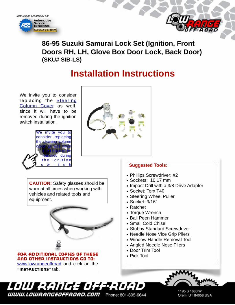
Suggested Tools:
• Phillips Screwdriver: #2 • Sockets: 10,17 mm • Impact Drill with a 3/8 Drive Adapter • Socket: Torx T40• Steering Wheel Puller• Socket: 9/16”• Ratchet• Torque Wrench• Ball Peen Hammer• Small Cold Chisel • Stubby Standard Screwdriver• Needle Nose Vice Grip Pliers• Window Handle Removal Tool• Angled Needle Nose Pliers• Door Trim Tool• Pick Tool
CAUTION: Safety glasses should be worn at all times when working with vehicles and related tools and equipment.
86-95 Suzuki Samurai Lock Set (Ignition, Front Doors RH, LH, Glove Box Door Lock, Back Door) (SKU# SIB-LS)
Installation Instructions
For additional copies of these and other instructions go to:www.lowrangeoffroad and click on the “Instructions” tab.
Instructions Created by an:
We invite you to consider replacing the Steering Column Cover as well, since it will have to be removed during the ignition switch installation.
We invite you to consider replacing the steering column cover as well since
it will have to be removed during t h e i g n i t i o n s w i t c h
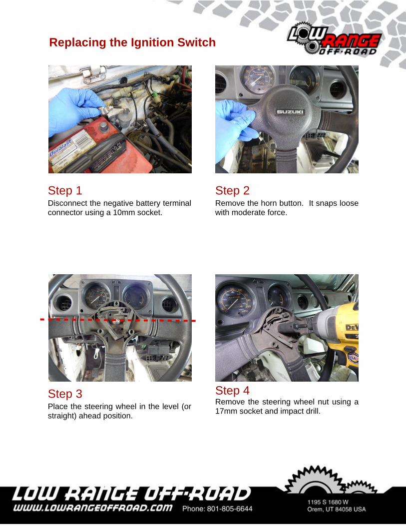
Step 2Remove the horn button. It snaps loose with moderate force.
Step 4Remove the steering wheel nut using a 17mm socket and impact drill.
Step 1Disconnect the negative battery terminal connector using a 10mm socket.
Step 3Place the steering wheel in the level (or straight) ahead position.
Replacing the Ignition Switch
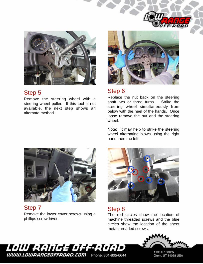
Step 5Remove the steering wheel with a steering wheel puller. If this tool is not available, the next step shows an alternate method.
Step 6Replace the nut back on the steering shaft two or three turns. Strike the steering wheel simultaneously from below with the heel of the hands. Once loose remove the nut and the steering wheel.
Note: It may help to strike the steering wheel alternating blows using the right hand then the left.
Step 8The red circles show the location of machine threaded screws and the blue circles show the location of the sheet metal threaded screws.
Step 7Remove the lower cover screws using a phillips screwdriver.
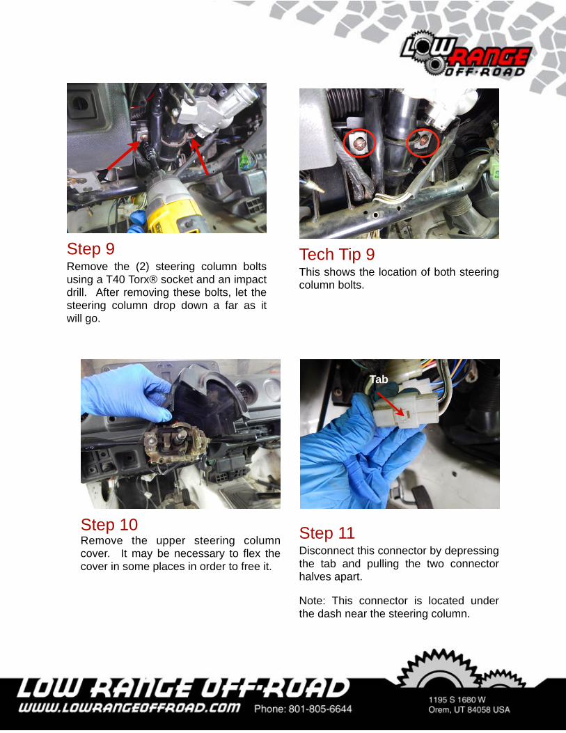
Step 10Remove the upper steering column cover. It may be necessary to flex the cover in some places in order to free it.
Step 11Disconnect this connector by depressing the tab and pulling the two connector halves apart.
Note: This connector is located under the dash near the steering column.
Tab
Step 9Remove the (2) steering column bolts using a T40 Torx® socket and an impact drill. After removing these bolts, let the steering column drop down a far as it will go.
Tech Tip 9This shows the location of both steering column bolts.
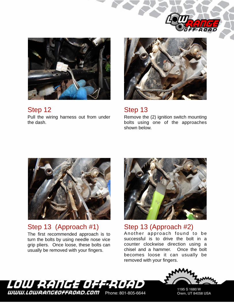
Step 13Remove the (2) ignition switch mounting bolts using one of the approaches shown below.
Step 12Pull the wiring harness out from under the dash.
Step 13 (Approach #2)Ano the r app roach found to be successful is to drive the bolt in a counter clockwise direction using a chisel and a hammer. Once the bolt becomes loose it can usually be removed with your fingers.
Step 13 (Approach #1)The first recommended approach is to turn the bolts by using needle nose vice grip pliers. Once loose, these bolts can usually be removed with your fingers.
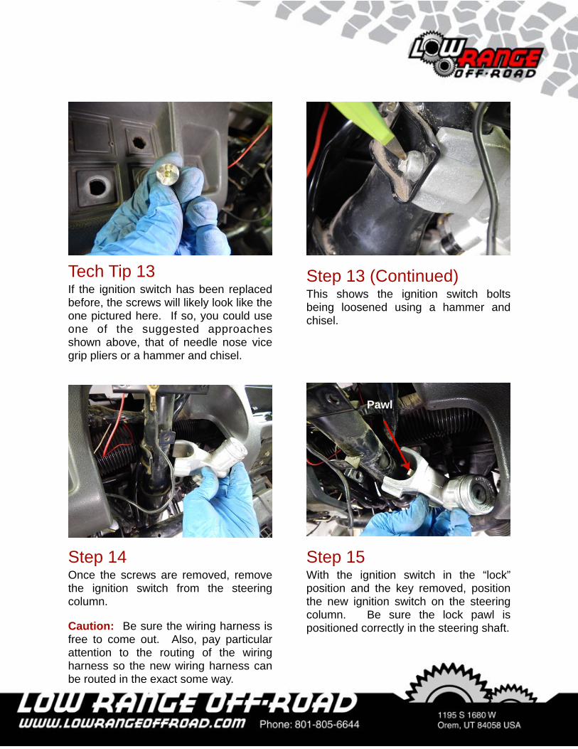
Step 13 (Continued)This shows the ignition switch bolts being loosened using a hammer and chisel.
Tech Tip 13If the ignition switch has been replaced before, the screws will likely look like the one pictured here. If so, you could use one of the suggested approaches shown above, that of needle nose vice grip pliers or a hammer and chisel.
Step 14Once the screws are removed, remove the ignition switch from the steering column.
Caution: Be sure the wiring harness is free to come out. Also, pay particular attention to the routing of the wiring harness so the new wiring harness can be routed in the exact some way.
Step 15With the ignition switch in the “lock” position and the key removed, position the new ignition switch on the steering column. Be sure the lock pawl is positioned correctly in the steering shaft.
Pawl
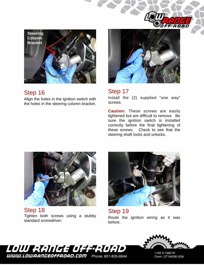
Step 16Align the holes in the ignition switch with the holes in the steering column bracket.
Step 18Tighten both screws using a stubby standard screwdriver.
Step 19Route the ignition wiring as it was before.
Steering Column Bracket
Step 17Install the (2) supplied “one way” screws.
Caution: These screws are easily tightened but are difficult to remove. Be sure the ignition switch is installed correctly before the final tightening of these screws. Check to see that the steering shaft locks and unlocks.
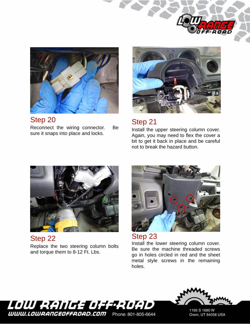
Step 21Install the upper steering column cover. Again, you may need to flex the cover a bit to get it back in place and be careful not to break the hazard button.
Step 22Replace the two steering column bolts and torque them to 8-12 Ft. Lbs.
Step 23Install the lower steering column cover. Be sure the machine threaded screws go in holes circled in red and the sheet metal style screws in the remaining holes.
Step 20Reconnect the wiring connector. Be sure it snaps into place and locks.
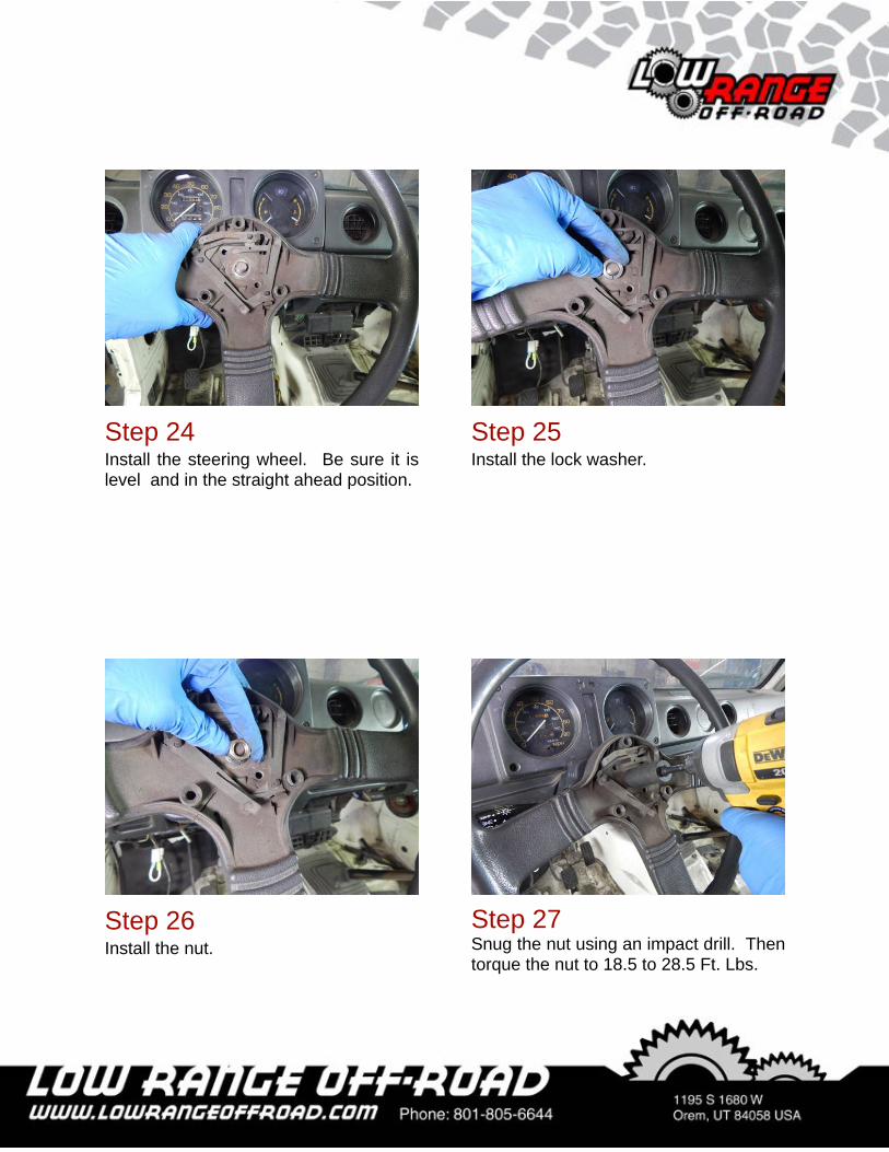
Step 25Install the lock washer.
Step 27Snug the nut using an impact drill. Then torque the nut to 18.5 to 28.5 Ft. Lbs.
Step 24Install the steering wheel. Be sure it is level and in the straight ahead position.
Step 26Install the nut.
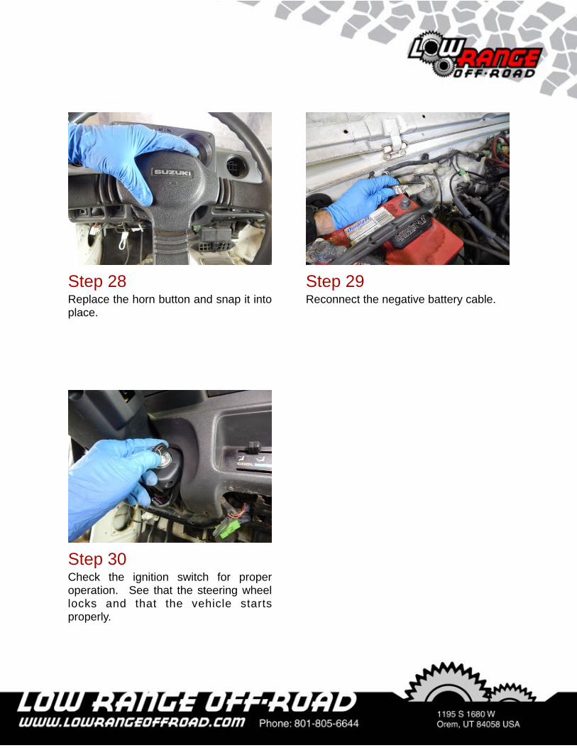
Step 29Reconnect the negative battery cable.
Step 28Replace the horn button and snap it into place.
Step 30Check the ignition switch for proper operation. See that the steering wheel locks and that the vehicle starts properly.
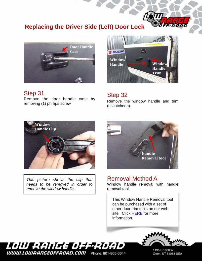
Step 32Remove the window handle and trim (escutcheon).
This picture shows the clip that needs to be removed in order to remove the window handle.
Removal Method AWindow handle removal with handle removal tool.
Step 31Remove the door handle case by removing (1) phillips screw.
Window'Handle
Handle'Removal'tool
Window'Handle'Clip
Door'Handle'Case'
This Window Handle Removal tool can be purchased with a set of other door trim tools on our web site. Click HERE for more information.
Window'Handle'Trim
Replacing the Driver Side (Left) Door Lock
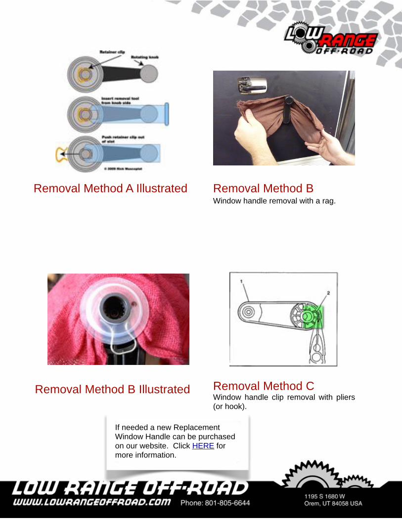
Removal Method BWindow handle removal with a rag.
Removal Method A Illustrated
Removal Method B Illustrated Removal Method CWindow handle clip removal with pliers (or hook).
If needed a new Replacement Window Handle can be purchased on our website. Click HERE for more information.
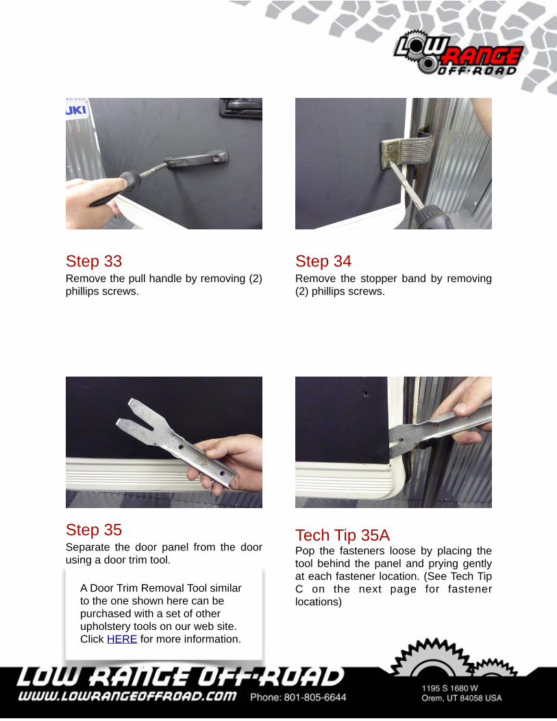
Step 34Remove the stopper band by removing (2) phillips screws.
Step 33Remove the pull handle by removing (2) phillips screws.
Tech Tip 35APop the fasteners loose by placing the tool behind the panel and prying gently at each fastener location. (See Tech Tip C on the next page for fastener locations)
Step 35Separate the door panel from the door using a door trim tool.
A Door Trim Removal Tool similar to the one shown here can be purchased with a set of other upholstery tools on our web site. Click HERE for more information.
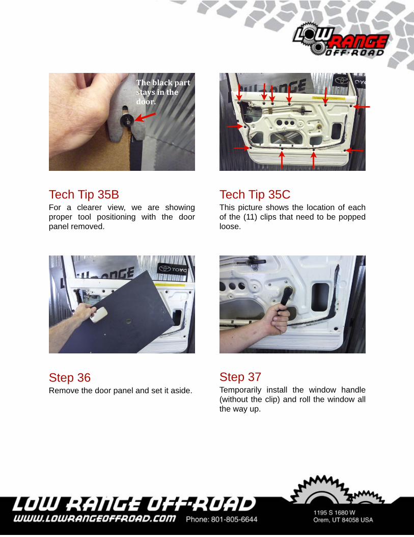
Tech Tip 35CThis picture shows the location of each of the (11) clips that need to be popped loose.
Tech Tip 35BFor a clearer view, we are showing proper tool positioning with the door panel removed.
Step 36Remove the door panel and set it aside.
The'black'part'stays'in'the'door.
Step 37Temporarily install the window handle (without the clip) and roll the window all the way up.
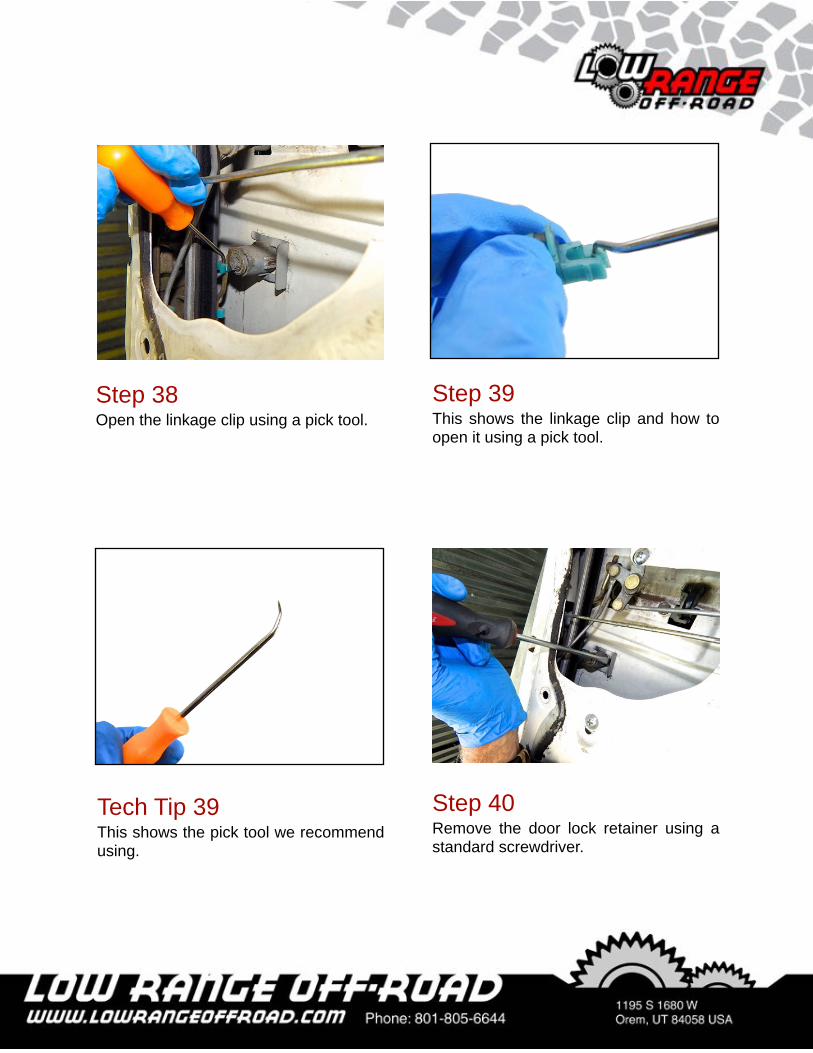
Step 38Open the linkage clip using a pick tool.
Step 39This shows the linkage clip and how to open it using a pick tool.
Tech Tip 39This shows the pick tool we recommend using.
Step 40Remove the door lock retainer using a standard screwdriver.
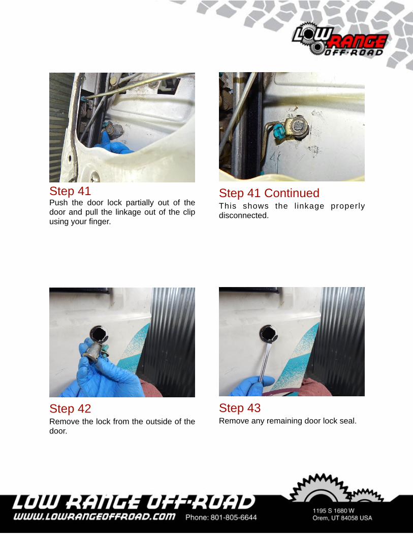
Step 41Push the door lock partially out of the door and pull the linkage out of the clip using your finger.
Step 41 ContinuedThis shows the l inkage properly disconnected.
Step 42Remove the lock from the outside of the door.
Step 43Remove any remaining door lock seal.
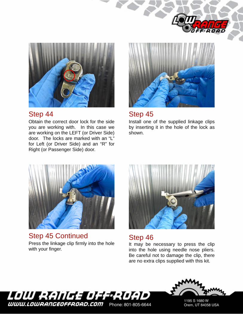
Step 45Install one of the supplied linkage clips by inserting it in the hole of the lock as shown.
Step 44Obtain the correct door lock for the side you are working with. In this case we are working on the LEFT (or Driver Side) door. The locks are marked with an “L” for Left (or Driver Side) and an “R” for Right (or Passenger Side) door.
Step 46It may be necessary to press the clip into the hole using needle nose pliers. Be careful not to damage the clip, there are no extra clips supplied with this kit.
Step 45 ContinuedPress the linkage clip firmly into the hole with your finger.
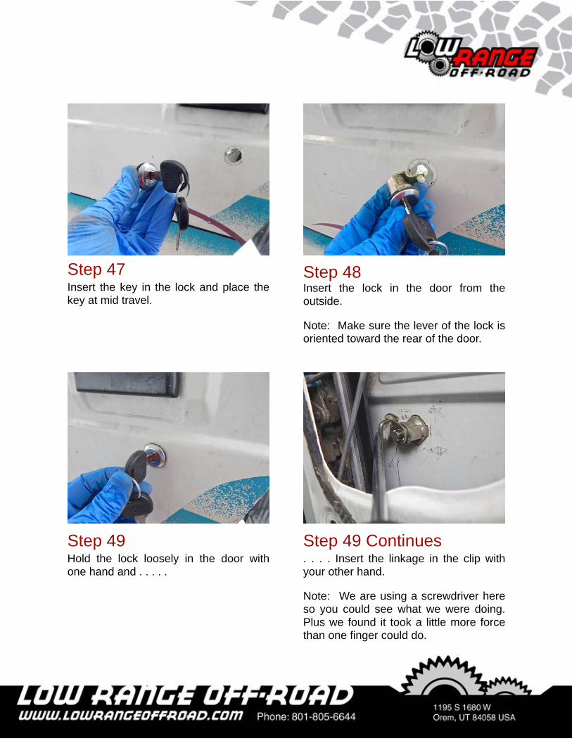
Step 48Insert the lock in the door from the outside.
Note: Make sure the lever of the lock is oriented toward the rear of the door.
Step 49 Continues. . . . Insert the linkage in the clip with your other hand.
Note: We are using a screwdriver here so you could see what we were doing. Plus we found it took a little more force than one finger could do.
Step 49Hold the lock loosely in the door with one hand and . . . . .
Step 47Insert the key in the lock and place the key at mid travel.
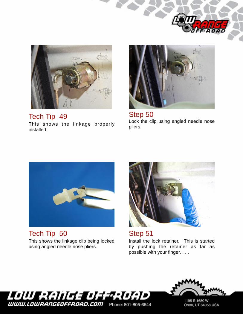
Step 50Lock the clip using angled needle nose pliers.
Tech Tip 49This shows the l inkage properly installed.
Step 51Install the lock retainer. This is started by pushing the retainer as far as possible with your finger. . . .
Tech Tip 50This shows the linkage clip being locked using angled needle nose pliers.
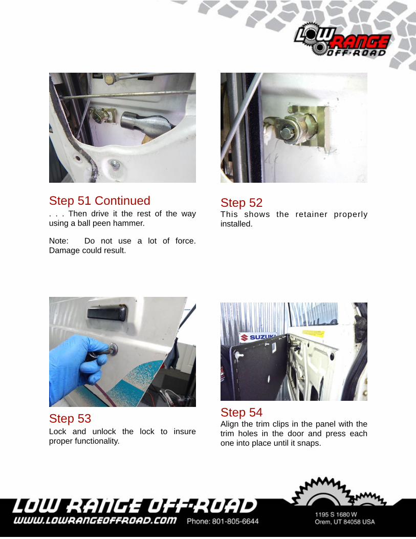
Step 52This shows the retainer properly installed.
Step 53Lock and unlock the lock to insure proper functionality.
Step 54Align the trim clips in the panel with the trim holes in the door and press each one into place until it snaps.
Step 51 Continued. . . Then drive it the rest of the way using a ball peen hammer.
Note: Do not use a lot of force. Damage could result.
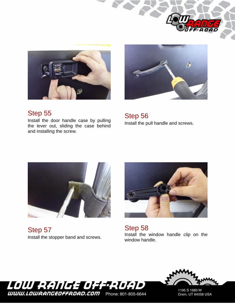
Step 56Install the pull handle and screws.
Step 57Install the stopper band and screws.
Step 55Install the door handle case by pulling the lever out, sliding the case behind and installing the screw.
Step 58Install the window handle clip on the window handle.
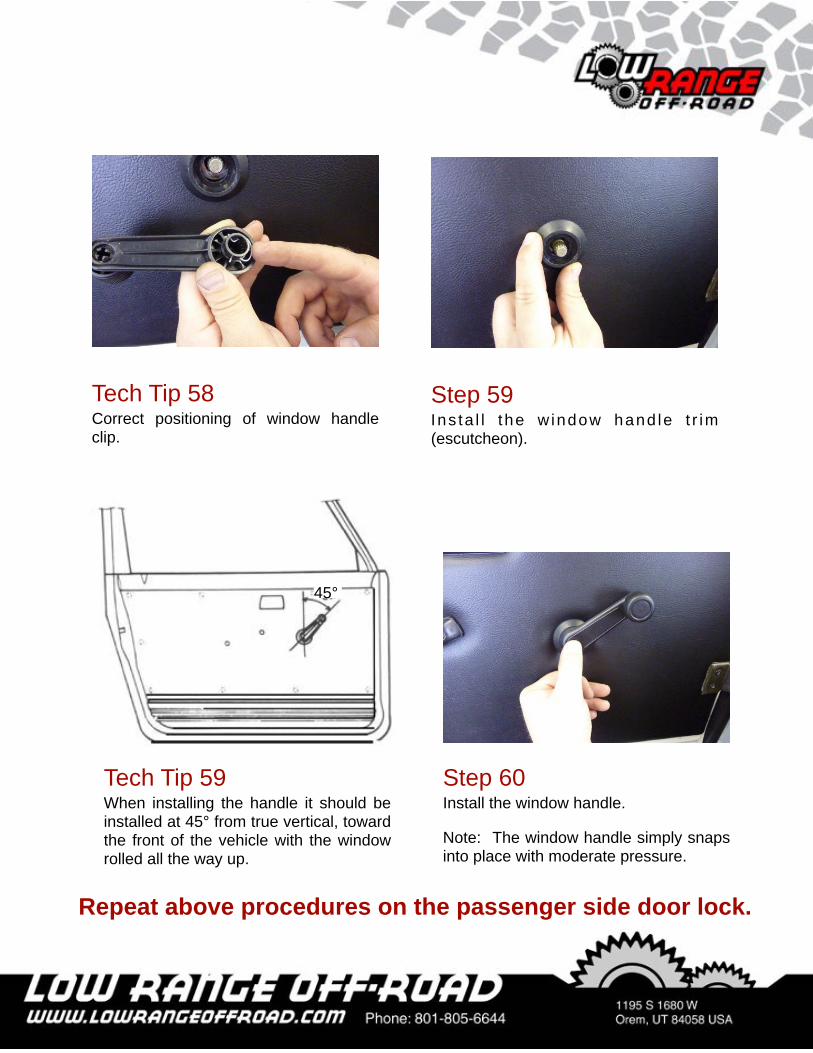
Step 59Ins ta l l the w indow hand le t r im (escutcheon).
Tech Tip 58Correct positioning of window handle clip.
45°
Tech Tip 59When installing the handle it should be installed at 45° from true vertical, toward the front of the vehicle with the window rolled all the way up.
Step 60Install the window handle.
Note: The window handle simply snaps into place with moderate pressure.
Repeat above procedures on the passenger side door lock.
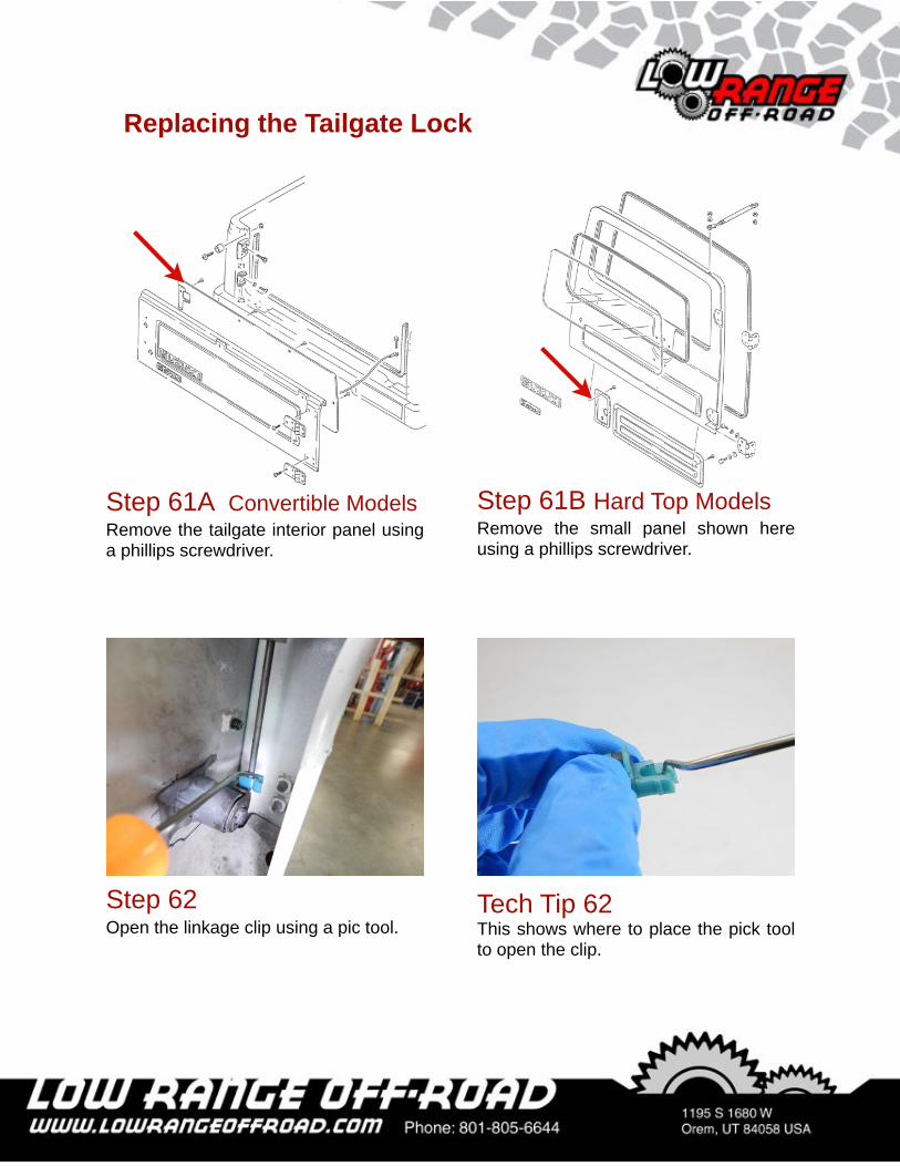
Step 61B Hard Top ModelsRemove the small panel shown here using a phillips screwdriver.
Step 61A Convertible ModelsRemove the tailgate interior panel using a phillips screwdriver.
Replacing the Tailgate Lock
Tech Tip 62 This shows where to place the pick tool to open the clip.
Step 62Open the linkage clip using a pic tool.
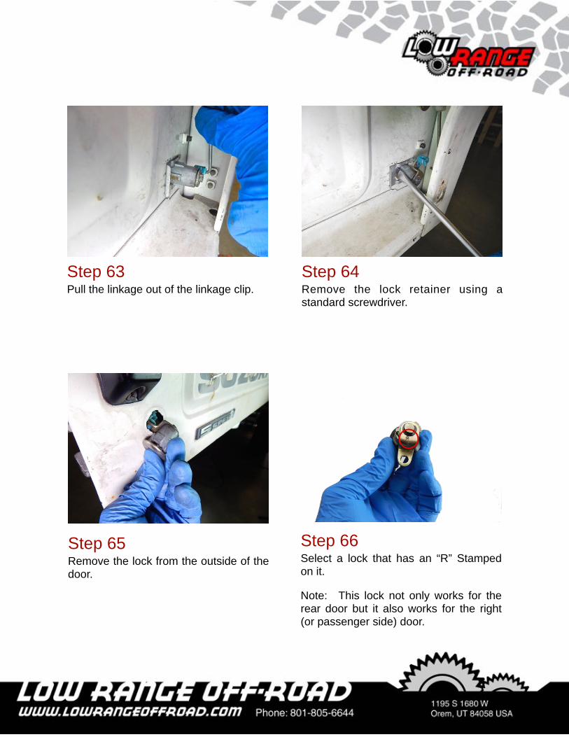
Step 64Remove the lock retainer using a standard screwdriver.
Step 63Pull the linkage out of the linkage clip.
Step 66Select a lock that has an “R” Stamped on it.
Note: This lock not only works for the rear door but it also works for the right (or passenger side) door.
Step 65Remove the lock from the outside of the door.
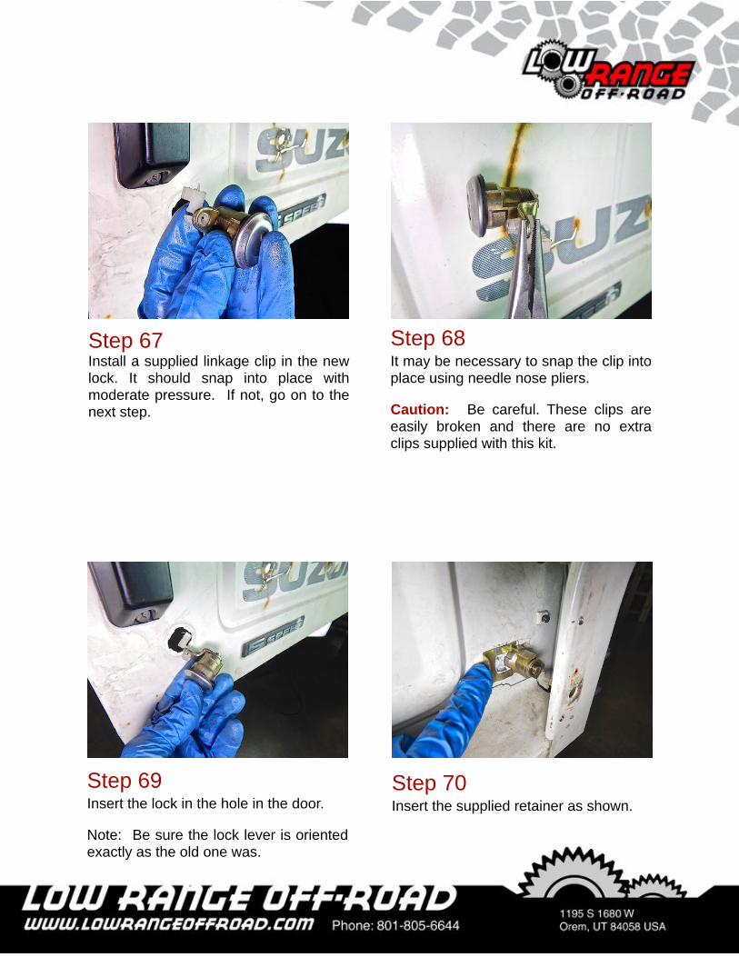
Step 67Install a supplied linkage clip in the new lock. It should snap into place with moderate pressure. If not, go on to the next step.
Step 68It may be necessary to snap the clip into place using needle nose pliers.
Caution: Be careful. These clips are easily broken and there are no extra clips supplied with this kit.
Step 69Insert the lock in the hole in the door.
Note: Be sure the lock lever is oriented exactly as the old one was.
Step 70Insert the supplied retainer as shown.
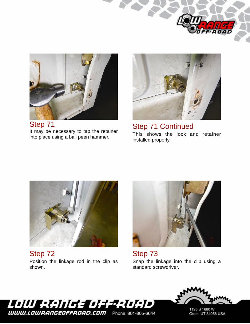
Step 71It may be necessary to tap the retainer into place using a ball peen hammer.
Step 71 ContinuedThis shows the lock and retainer installed properly.
Step 72Position the linkage rod in the clip as shown.
Step 73Snap the linkage into the clip using a standard screwdriver.
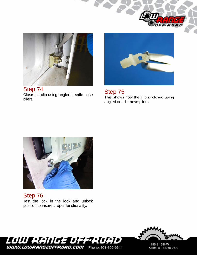
Step 74Close the clip using angled needle nose pliers
Step 75This shows how the clip is closed using angled needle nose pliers.
Step 76Test the lock in the lock and unlock position to insure proper functionality.
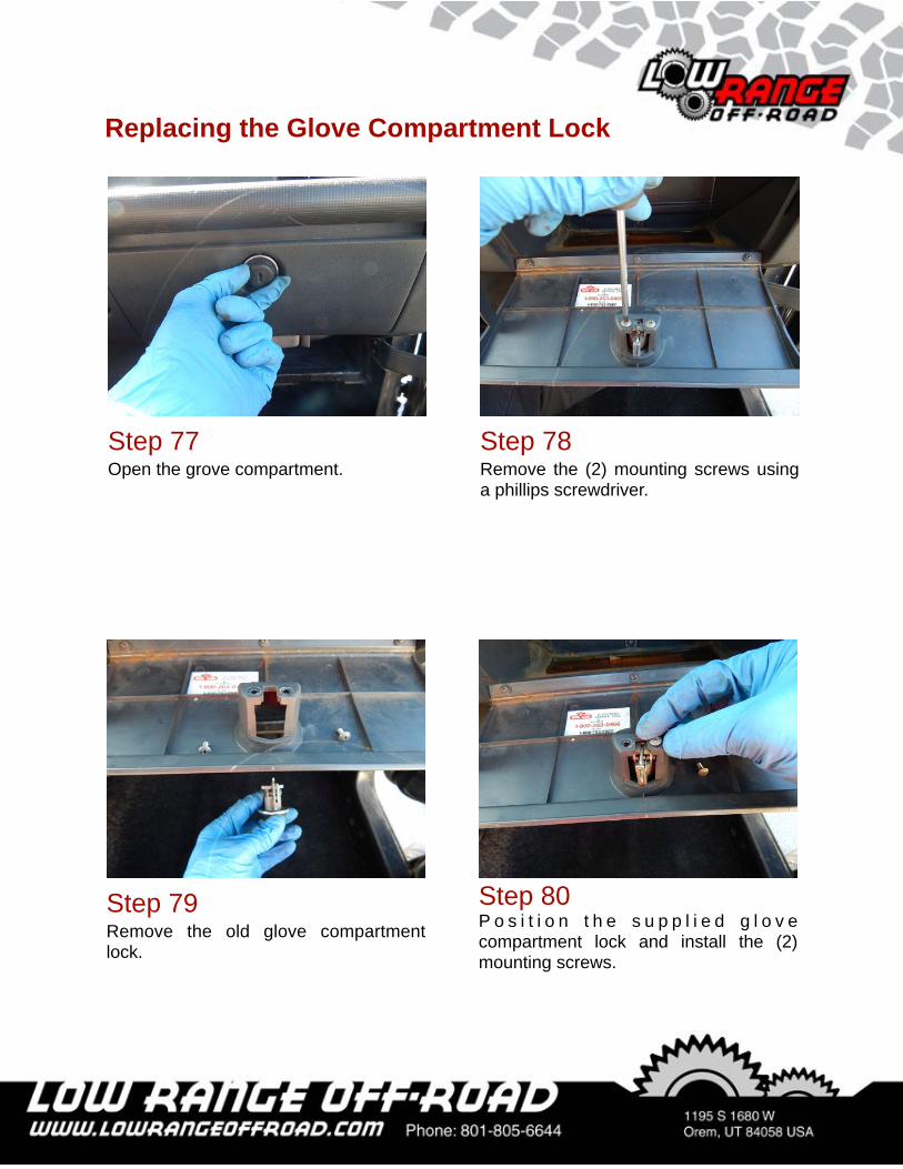
Step 78Remove the (2) mounting screws using a phillips screwdriver.
Step 77Open the grove compartment.
Replacing the Glove Compartment Lock
Step 80P o s i t i o n t h e s u p p l i e d g l o v e compartment lock and install the (2) mounting screws.
Step 79Remove the old glove compartment lock.
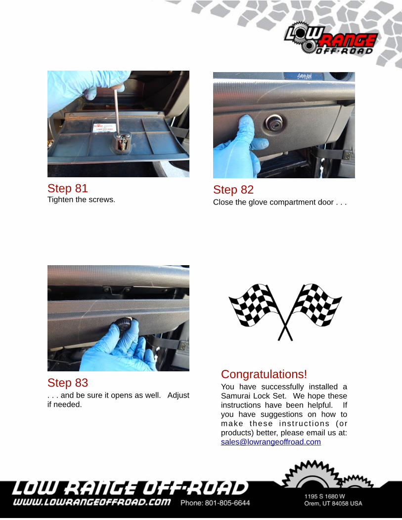
Step 82Close the glove compartment door . . .
Step 81Tighten the screws.
Step 83. . . and be sure it opens as well. Adjust if needed.
Congratulations!You have successfully installed a Samurai Lock Set. We hope these instructions have been helpful. If you have suggestions on how to make these ins t ruc t ions (or products) better, please email us at: [email protected]

As always, If you experience any difficulty during the installation of this product please contact Low Range Off-Road Technical Support at 801-805-6644 M-F during regular store hours. Thank you for purchasing from Low Range Off-Road.
These instructions are designed as a general installation guide. Installation of many Low Range Off-Road products require specialized skills such as metal fabrication, welding and mechanical trouble shooting. If you have any questions or are unsure about how to proceed, please contact our shop at 801-805-6644 or seek help from a competent fabricator. Using fabrication tools such as welders, torches and grinders can cause serious bodily harm and death. Please operate equipment carefully and observe proper safety procedures.
Rock crawling and off-road driving are inherently dangerous activities. Some modifications will adversely affect the on-road handling characteristics of your vehicle. All products sold by Low Range Off-Road are sold for off road use only. Any other use or application is the responsibility of the purchaser and/or user. Some modifications and installation of certain aftermarket parts may under certain circumstances void your original dealer warranty. Modification of your vehicle may create dangerous conditions, which could cause roll-overs resulting in serious bodily injury or death. Buyers and users of these products hereby expressly assume all risks associated with any such modifications and use.
Revised 09/24/15© Copyright 2015 Low Range Off-Road, LC All Rights Reserved