Embed Size (px)
Citation preview

SIBS® 4 WORKSHOP MANUAL
FORD RANGER

SIBS 4 WORKSHOP MANUAL - FORD RANGER (REV 1) 31 AUG 2015
2
1. Revision History
Revision Issue Date Author Comments
1 31 Aug 2015 J. Leighton Initial Release
© Advanced Braking Pty Ltd, 2015.
All rights reserved. No part of this manual may be reproduced in any form or by any means without the prior written consent from the copyright holder. While every attempt is made to ensure that the information in this manual is correct, no liability can be accepted by the authors for loss, damage or injury caused by any errors in, or omissions from, the information given.
SIBS 4 WORKSHOP MANUAL - FORD RANGER (REV 1) 31 AUG 2015
3
2. Table of Contents 1. Revision History ....................................................................................................................................................................... 2
2. Table of Contents..................................................................................................................................................................... 3
3. Important Information ............................................................................................................................................................ 4
4. Terminology ............................................................................................................................................................................. 5
5. Exploded Views & Parts Lists - Rear Brake Assembly .............................................................................................................. 6
6. Wiring Diagram ...................................................................................................................................................................... 10
7. Installation – Rear Brakes ...................................................................................................................................................... 12
8. Installation – Hydraulic System ............................................................................................................................................. 25
9. Installation – Electrical System .............................................................................................................................................. 29
10. Pre-Service Inspection ........................................................................................................................................................... 33
11. Controller Setup..................................................................................................................................................................... 36
12. Service Schedule .................................................................................................................................................................... 37
13. Pre-Start Check ...................................................................................................................................................................... 38
14. Minor Service ......................................................................................................................................................................... 39
15. Major Service – Rear .............................................................................................................................................................. 40
16. Troubleshooting..................................................................................................................................................................... 47

SIBS 4 WORKSHOP MANUAL - FORD RANGER (REV 1) 31 AUG 2015
4
3. Important Information This manual applies to the fourth generation Sealed Integrated Braking System (SIBS® 4) for the Ford Ranger. The manual details how to install the SIBS® 4 system correctly to ensure optimum safety and performance. All information contained in this manual is based on the latest SIBS® product information available at the time of publication.
This manual should be read in conjunction with the appropriate Ford vehicle manual for further information on removal and installation of any standard Ford components.
While every effort has been made to address all aspects of installation and servicing, please advise Advanced Braking of any omissions or suggestions on how this manual may be improved.
Advanced Braking Pty Ltd reserves the right to change the manual at any time without prior notice.
The most up to date version of the manual can be obtained by contacting the ABT Customer Service Manager.
The SIBS® and EMMA™ trademarks are owned by Advanced Braking Pty Ltd.
Street Address: Advanced Braking Pty Ltd Unit 1, 3 McDonald Street West Osborne Park WA 6017 AUSTRALIA
Postal address: PO Box 1177 Osborne Park WA 6916 AUSTRALIA
E-mail: [email protected]
Website: www.advancedbraking.com
Phone: +61 (08) 9273 4800
Fax: +61 (08) 9201 9986

SIBS 4 WORKSHOP MANUAL - FORD RANGER (REV 1) 31 AUG 2015
5
4. Terminology
ABS Anti-lock braking system
ATF Automatic transmission fluid
DPS Door proximity system
Emergency Brake Brakes automatically applied in an emergency
EMMA™ Electronically Modulated Mechanically Applied
HSI Highway speed isolation
OEM Original equipment manufacturer
Park Brake Brakes applied independently of the service brake
PWI Pad wear indicator
Service Brake Brakes applied when driving via the foot pedal
SIBS® Sealed Integrated Braking System
SIBS® Cooling Fluid Specially formulated cooling fluid for use in SIBS® brakes

SIBS 4 WORKSHOP MANUAL - FORD RANGER (REV 1) 31 AUG 2015
6
5. Exploded Views & Parts Lists - Rear Brake Assembly

SIBS 4 WORKSHOP MANUAL - FORD RANGER (REV 1) 31 AUG 2015
7
ITEM PART NO. DESCRIPTION QTY/KIT (2 BRAKES)
TORQUE (Nm)
1 14-2006 CAP HUB REAR 2 -
2 30-9001 NUT LOCK REAR HUB 2 60
3 31-3001 CIRCLIP OUTER DRIVE ADAPTER 2 -
4 31-3002 CIRCLIP INNER DRIVE ADAPTER 2 -
5 31-6000 BEARING WHEEL OUTER 2 -
6 31-6001 BEARING WHEEL INNER 2 -
7 31-4001 SEAL HUB 4 -
8 45-2011 STUD WHEEL 12 -
9 31-4000 SEAL V-LIP 2 -
10 45-4004 HUB ASSEMBLY REAR 2 -
11 31-5008 NIPPLE GREASE 2 10
12 30-9002 WASHER LOCK REAR HUB 2 -
13 25-9010 SEAL OIL REAR AXLE 2 -
14 25-2049 SEAL CASSETTE HOUSING 2 -
15 30-0003 BOLT HOUSING 24 50
16 45-2000 HOUSING OUTER REAR LH 1 -
45-2001 HOUSING OUTER REAR RH 1 -
17 24-2860 BRAKE PAD - ACW 4 -
18 25-2000 ROTOR 2 -
19 24-2850 BRAKE PAD – CW 4 -
20 31-2006 O-RING HOUSING 2 -
21 31-2005 O-RING SERVICE WIPER REAR 4 -
22 30-0061 BOLT MOUNTING REAR BRAKE 8 80
23 14-2002 SPINDLE REAR AXLE 2 -
24 14-5003 HOUSING INNER REAR LH W/PINS 1 -
14-5004 HOUSING INNER REAR RH W/PINS 1 -
25 31-5001 BLEED NIPPLE 8 15

SIBS 4 WORKSHOP MANUAL - FORD RANGER (REV 1) 31 AUG 2015
8
26 31-9000 CAP BLEED NIPPLE 8 -
27 31-5032 CONNECTOR HOSE BREATHER 2 15
28 25-2038 FILL PLUG 2 20
29 25-9000 NUT MOUNTING REAR BRAKE 8 80
30 30-2004 WASHER SEALING COPPER 6 -
31 25-4025 LINK HOSE SERVICE BRAKE 2 15
32 31-5026 CONNECTOR PIPE SERVICE BRAKE 6 20
33 31-5000 CONNECTOR HOSE EMMA 2 20
34 30-2009 WASHER LOCK MOUNTING REAR BRAKE 8 -
35 30-0017 BOLT MOUNTING SPINDLE REAR 22 35
36 25-2039 DRAIN PLUG 2 20
37 30-2003 WASHER SEALING COPPER 4 -
38 30-2006 WASHER FLAT MOUNTING REAR BRAKE 8 -
39 25-2025 PISTON SERVICE REAR 4 -
40 31-2004 O-RING SERVICE PRIMARY REAR 4 -
41 31-5004 PLUG SPRING COVER 6 -
42 30-0028 RETRACTOR BOLT 8 80
43 25-2041 GLAND PAD WEAR INDICATOR 2 15
44 25-2042 CAP PAD WEAR INDICATOR 2 10
45 30-2005 WASHER SEALING PAD WEAR INDICATOR 2 -
46 25-2040 PLUNGER PAD WEAR INDICATOR 2 15
47 30-0001 BOLT SPRING COVER 20 60
48 30-2000 WASHER SPRING COVER 20 -
49 25-2008 SPRING COVER LH 1 -
25-2009 SPRING COVER RH 1 -
50 31-0002 DISC SPRING 48 -
51 25-2006 PISTON EMMA 8 -
52 25-2061 GASKET SPRING COVER 2 -
53 31-2003 BACK-UP RING EMMA LARGE 8 -

SIBS 4 WORKSHOP MANUAL - FORD RANGER (REV 1) 31 AUG 2015
9
54 31-2002 O-RING EMMA LARGE 8 -
55 31-2000 O-RING EMMA SMALL 8 -
56 31-2001 BACK-UP RING EMMA SMALL 8 -
57 14-2009 ROTOR ABS 2 -
58 14-2004 SHAFT AXLE REAR 2 -
59 31-2013 O-RING SHAFT AXLE 2 -
60 14-2005 DRIVE ADAPTER REAR AXLE 2 -
61 31-3000 CIRCLIP REAR AXLE 2 -
62 14-4005 SHAFT AXLE ASSEMBLY REAR 2 -
63 14-5000 KIT SERVICE REAR SET SIBS 4 1 -
64 14-5001 KIT MOUNTING REAR SET SIBS 4 1 -
65 14-5002 KIT INSPECTION BRAKE PAIR 1 -
66 25-5004 KIT WHEEL BEARING PAIR 1 -

SIBS 4 WORKSHOP MANUAL - FORD RANGER (REV 1) 31 AUG 2015
10
6. Wiring Diagram

SIBS 4 WORKSHOP MANUAL - FORD RANGER (REV 1) 31 AUG 2015
11

SIBS 4 WORKSHOP MANUAL - FORD RANGER (REV 1) 31 AUG 2015
12
7. Installation – Rear Brakes 1. Ensure all OEM Ford rear brake equipment has been removed from the vehicle:
a. Remove both rear brake assemblies.
b. Remove the two hydraulic brake lines across the rear axle.
c. Remove the handbrake lever and handbrake cable.
d. Remove the axles with bearings and ABS pulse wheels.
2. Using a suitable lifting hoist, remove the SIBS® 4 wheel-end assembly from its packaging and sit on a bench.
3. Remove the 12x housing screws and set aside for re-use later.
Figure 1: Brake assembly as received in kit.
4. Lift the outer brake housing and rotor off as one assembly and set aside.
Figure 2: Split the inner and outer brake housings.

SIBS 4 WORKSHOP MANUAL - FORD RANGER (REV 1) 31 AUG 2015
13
5. Clean the vehicle axle flange and spindle to remove any grease, dirt and gasket remains. If the flange is damaged or corroded it must be cleaned thoroughly with abrasive paper.
Figure 3: Clean and prepare the axle flange face.
6. Insert the axle shaft with the ABS pulse wheel.
Figure 4: Axle with pulse wheel inserted into diff housing.

SIBS 4 WORKSHOP MANUAL - FORD RANGER (REV 1) 31 AUG 2015
14
7. Apply a ring of Loctite® 515™ directly to the axle flange face.
Figure 5: Apply a ring of Loctite® 515™ to the axle flange face.
8. Each brake unit is stamped with its corresponding position on the vehicle and must be installed accordingly:
a. RLH = Rear Left Hand
b. RRH = Rear Right Hand
9. Fit the SIBS® 4 inner brake housing and stub axle to the axle flange face. Align the mounting holes and locate the housing evenly and firmly against the axle flange.
Figure 6: Mount inner brake housing to the axle flange.
SIBS 4 WORKSHOP MANUAL - FORD RANGER (REV 1) 31 AUG 2015
15
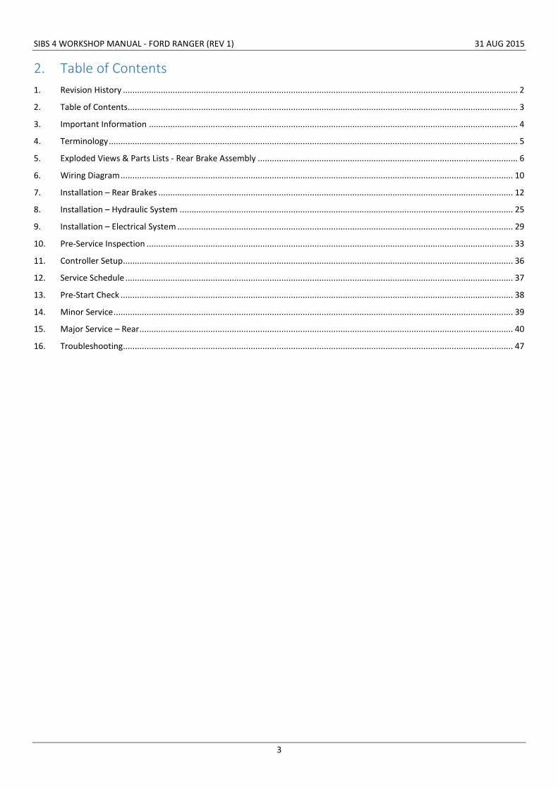
10. Apply Loctite® 515™ around the mounting holes to ensure a good seal around the heads of the mounting bolts.
Figure 7: Seal fastener holes by applying Loctite® 515™ to the fastener mounting faces.
11. Secure the inner brake housing and stub axle to the vehicle using the 4x mounting bolts, disc lock washers and nuts; torque each fastener twice in a diagonal pattern to 80 Nm.
Figure 8: Secure inner brake housing to axle flange using mounting fasteners.

SIBS 4 WORKSHOP MANUAL - FORD RANGER (REV 1) 31 AUG 2015
16
12. Install 2x guide pins in the inner brake housing at the 3o’clock and 9o’clock positions.
Figure 9: Install guide pins in inner brake housing.
13. Install brake pads in the inner brake housing ensuring correct orientation (RH brake shown in image).
Figure 10: Install brake pads in inner brake housing (RRH brake shown).
SIBS 4 WORKSHOP MANUAL - FORD RANGER (REV 1) 31 AUG 2015
17
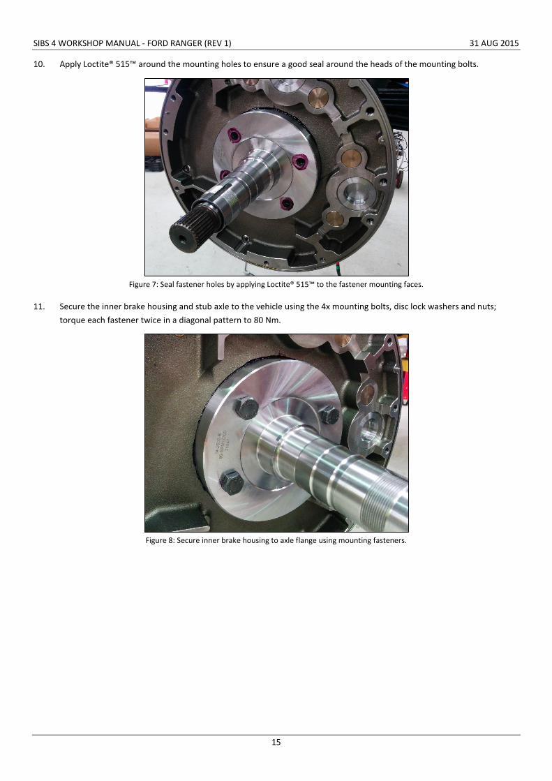
14. Using guide pins to assist, assemble the outer brake housing, hub and rotor as one piece with the inner brake housing.
Figure 11: Mount the outer brake housing, rotor and hub assembly using guide pins to assist.
15. Secure the inner and outer brake housings together using 12x housing screws; torque each fastener to 50 Nm at least twice.
Figure 12: Secure the inner and outer brake housing using housing bolts.

SIBS 4 WORKSHOP MANUAL - FORD RANGER (REV 1) 31 AUG 2015
18
16. Install the outer hub bearing, locking plate and nut; torque to 60 Nm. Lock the nut in place by bending down one of the tabs on the locking plate.
Figure 13: Install inner bearing, locking plate and hub nut.
17. Fit the V-slip seal over the hub ensuring the square edge locates on the hub and the lip against the outer brake housing.
18. Fill the cavity behind the V-lip seal with a high temperature bearing grease (Castrol LMX recommended) via the grease nipple located on the hub face. Do not over-grease the V-lip cavity.
Figure 14: Fit V-lip seal over hub.

SIBS 4 WORKSHOP MANUAL - FORD RANGER (REV 1) 31 AUG 2015
19
19. Install the small internal circlip in the groove behind the internal spline in the hub.
Figure 15: Install internal circlip in hub.
20. Apply a light smear of silicone grease (Parker Super O Lube recommended) to the O-ring then fit over the axle shaft outer spline.
Figure 16: Install lubricated O-ring onto axle.

SIBS 4 WORKSHOP MANUAL - FORD RANGER (REV 1) 31 AUG 2015
20
21. Apply a light smear of grease to the splines of the drive adapter then install between the hub and axle ensuring the inner and outer splines are correctly engaged.
Figure 17: Install the drive adapter between the hub and axle.
22. Secure the drive adapter by installing the large internal circlip in the hub groove.
Figure 18: Install the large internal circlip in the hub.

SIBS 4 WORKSHOP MANUAL - FORD RANGER (REV 1) 31 AUG 2015
21
23. Secure the axle shaft by fitting the small external circlip into the groove. An M8 fastener may be installed in the end of the axle to assist in fitment to assist in fitment of the circlip by pulling the axle outward.
Figure 19: Install the small external circlip on the axle shaft.
24. Install the hub cap onto the hub, tap into position with a rubber mallet or similar.
Figure 20: Fit the hub cap.

SIBS 4 WORKSHOP MANUAL - FORD RANGER (REV 1) 31 AUG 2015
22
25. Remove the 4x retractor bolts from the spring cover.
26. In order to remove the top 2x retractor bolts the 4x suspension U-bolt nuts may need to be loosened or removed; refer to the Ford Ranger workshop manual for the appropriate procedure (installation torque for these nuts is 120 Nm).
27. Fit the pad wear indicator to the lowest piston:
a. Screw the pad wear indicator piston into the lowest piston thread and torque to 10 Nm.
b. Fit the stainless steel gland fitting over the piston and screw this into the spring cover.
c. Fit the stainless steel protective cover and fibre washer to the gland fitting.
Figure 21: Pad wear indicator installed in spring cover.
28. Fit 3x supplied tapered plugs to seal the remaining holes in the spring cover. The hex sockets may be filled with silicon to aid future removal.
Figure 22: Tapered plugs and PWI installed in spring cover.
29. Remove the SIBS® cooling fluid fill plug.
30. Fill the SIBS® 4 brake unit with new SIBS® cooling fluid and refit the fill plug with a new copper washer. Approximately 1 litre of SIBS® cooling fluid is required per brake unit.
31. Repeat for the opposing brake unit.
PWI plunger
PWI cap
PWI gland
Pad wear indicator
3x tapered plugs

SIBS 4 WORKSHOP MANUAL - FORD RANGER (REV 1) 31 AUG 2015
23
32. Fit the wheels and wheel nuts; torque in a criss-cross pattern as per the Ford Ranger workshop manual (88.2 - 117.6 Nm).
Figure 23: Fit wheels and torque wheel nuts.

SIBS 4 WORKSHOP MANUAL - FORD RANGER (REV 1) 31 AUG 2015
24
33. Fit the expansion chambers:
a. There is one expansion chamber per brake unit.
b. Mount the expansion chambers as high as possible in a protected location on the vehicle. ABT recommends mounting between the cab and the tray.
c. Secure using the supplied mounting hardware.
34. Run lengths of breather hose between the expansion chambers and their corresponding brake units.
a. Route the breather hose from the brake units, along the axle to the diff centre and then up towards the front of the tray.
b. Route the hose away from the exhaust and any moving components. Allow extra length for axle articulation.
c. Protect areas of the hose that may abrade using spiral guard.
d. Ensure SIBS® fluid can easily drain back into the brake housings.
e. Secure the hoses using supplied P-clips.
Figure 24: Expansion chamber mounted between cab and tray.
Figure 25: Expansion chamber.
Expansion chamber
Breather hose to brake unit
Breather filter

SIBS 4 WORKSHOP MANUAL - FORD RANGER (REV 1) 31 AUG 2015
25
8. Installation – Hydraulic System 1. Mount the SIBS® 4 pump enclosure in a suitable location on the vehicle. ABT recommends the following locations:
a. On single-cabs mount the pump behind the driver’s seat using the supplied bracket.
b. On dual-cabs mount the pump under the tray behind the rear left wheel using the supplied bracket.
c. Drill the vehicle body as required and mount the SIBS® pump using provided mounting hardware.
Figure 26: SIBS® 4 pump enclosure.
2. Mount the park/emergency brake tee-union on the top of the diff centre.
Figure 27: Park/emergency brake tee-union mounted to top of diff centre.
Emergency brake tee-union

SIBS 4 WORKSHOP MANUAL - FORD RANGER (REV 1) 31 AUG 2015
26
3. Connect one end of the park/emergency brake hydraulic hose to the bulkhead fitting at the rear of the pump enclosure.
4. Route the other end of the hydraulic hose down to the tee-union on the rear axle and connect. Secure the hose along the chassis using supplied P-clips.
Figure 28: Park/emergency brake lines and breather hose routed to front of vehicle.

SIBS 4 WORKSHOP MANUAL - FORD RANGER (REV 1) 31 AUG 2015
27
5. Fit the rear RH service brake line.
a. Connect one end of the RH service brake line to the rear RH supply hose and the other end to the inlet on the RH brake unit.
b. Secure the brake line using supplied P-clips in the OEM locations.
6. Fit the rear RH park/emergency brake hydraulic hose.
a. Connect one end of the RH park/emergency brake hydraulic hose to the tee-union on the rear diff.
b. Connect the other end to the inlet on the RH brake unit.
c. Secure the hydraulic hose along the rear axle using P-clips. Ensure the hose will not contact any moving suspension components.
Figure 29: Brake lines routed to rear RH brake unit (facing rear of vehicle).
Figure 30: Brake lines routed to rear RH brake unit (facing front of vehicle).

SIBS 4 WORKSHOP MANUAL - FORD RANGER (REV 1) 31 AUG 2015
28
7. Fit the rear LH service brake line.
a. Connect one end of the LH service brake line to the rear LH supply hose and the other end to the inlet on the LH brake unit.
b. Secure the brake line using supplied P-clips in the OEM locations.
8. Fit the rear LH park/emergency brake hydraulic hose.
a. Connect one end of the LH park/emergency brake hydraulic hose to the tee-union on the rear axle.
b. Route the hydraulic hose across the rear axle and connect to the inlet on the LH brake unit.
c. Secure the hydraulic hose along the rear axle using P-clips. Ensure the hose will not contact any moving suspension components.
Figure 31: Brake lines routed to rear LH brake unit (facing rear of vehicle).
Figure 32: Brake lines routed to rear LH brake unit (facing front of vehicle).

SIBS 4 WORKSHOP MANUAL - FORD RANGER (REV 1) 31 AUG 2015
29
9. Installation – Electrical System 1. Isolate the vehicle battery.
2. Do not test the SIBS® controller function until the system is fully installed as this may confuse the SIBS® controller while learning – details on controller setup can be found in section 11.
3. Mount the SIBS® controller to the dash:
a. Remove the trim around the vehicle radio.
b. Mount the SIBS® controller on the dash using the provided bracket. Position so that bracket is central on the dash and aligned with the vehicle axis. 4x holes will need to be drilled.
c. For LH drive vehicles the SIBS® controller bracket can be reversed so that it is always facing the vehicle operator.
Figure 33: SIBS® 4 controller mounted on dash.
4. Fit the SIBS® cabin harness:
a. Remove the glove box, seats and vinyl floor mats.
b. Drill a Ø30 mm hole behind the SIBS® controller and feed the cabin harness through all the way up to the square 26-pin connector which should be connected to the rear of the SIBS® controller. Seal the hole around the harness using the attached grommet.
c. Route the harness down behind the dash to the passenger side of the transmission tunnel.
d. Route the cabin harness along the transmission tunnel and connect to the pump enclosure. Some vehicles may require an extension harness to reach the pump enclosure, if so this will be provided with the kit.
e. Secure the harness where necessary using P-clips.

SIBS 4 WORKSHOP MANUAL - FORD RANGER (REV 1) 31 AUG 2015
30
5. Fit the vehicle interface harness:
a. Remove the trim around the instrument cluster.
b. Remove the vehicle instrument cluster by removing 3x retaining screws and disconnecting the multi-plug at the rear.
Figure 34: Instrument cluster retaining screws.
c. Connect the Deutsch end of the vehicle interface harness to the 6 pin connector on the SIBS® cabin harness located behind the radio.
d. Route the harness toward the cavity at the rear of the instrument cluster.
e. Solder splice the blue/white wire (ignition feed) from pin 3 of the SIBS® harness to the yellow wire from pin 18 of the instrument cluster connector.
Figure 35: Splice the SIBS® harness with the OEM instrument cluster harness.

SIBS 4 WORKSHOP MANUAL - FORD RANGER (REV 1) 31 AUG 2015
31
6. Fit the engine bay harness:
a. Connect the engine bay harness to the 2x 2-pin connectors on the cabin harness located beside the passenger foot well.
b. Route the engine bay harness through the grommet in the passenger foot well and into the engine bay.
Figure 36: Route the engine bay harness through the firewall grommet in the engine bay.
c. Route the engine bay harness through the engine bay and connect the red wires to the positive battery terminal via the eyelet.
d. Connect the black wire to a vehicle earth point via the eyelet.
e. Secure the relay in a suitable location in the engine bay.
f. Secure the harness where necessary using P-clips.

SIBS 4 WORKSHOP MANUAL - FORD RANGER (REV 1) 31 AUG 2015
32
7. Fit the door proximity harness (optional):
a. Connect the door proximity harness to the 3 pin connector on the cabin harness located behind the radio.
b. Dependent on how many doors have been specified will affect the number of proximity switches included in the harness.
c. Drill Ø12 mm holes in the door pillars to mount the proximity switches. Suggested location is in the A-pillar for front doors. Note: The A-pillar is double skinned therefore a clearance hole will need to be drilled through the first layer so the proximity switch can be mounted securely.
Figure 37: Drill a clearance hole in the A-pillar to fit the proximity switch.
d. Secure the proximity switch to the door pillar such that there is a 1.0 mm gap between the tip of the proximity switch and door frame when the door is closed.
Figure 38: Secure proximity switch with locknuts.
e. Run the extensions and connect to the proximity switches.
f. For every proximity switch to be added, an additional Y-split harness must be installed.
8. Replace the instrument cluster, radio, glove box, seats, mats and all vehicle trim.

SIBS 4 WORKSHOP MANUAL - FORD RANGER (REV 1) 31 AUG 2015
33
10. Pre-Service Inspection 1. Top up all reservoirs with the specified fluids.
a. Use DOT 3 brake fluid for the brake master cylinder (service system).
b. Use ATF Dexron III for the SIBS® pump reservoir (park/emergency system).
Figure 39: SIBS® 4 pump enclosure with lid removed.
2. Ensure the battery is in good condition – this is critical to ensure correct programming of the SIBS® controller.
3. Reconnect the vehicle battery to power the vehicle and SIBS® system.
Filler cap
Fill level

SIBS 4 WORKSHOP MANUAL - FORD RANGER (REV 1) 31 AUG 2015
34
4. Bleed the service brake system:
a. Connect a clear vinyl tube onto the service brake bleed nipple and the other into a clean container of brake fluid.
b. Slowly pump the brake pedal several times.
c. While an assistant presses on the brake pedal, loosen the bleed nipple until fluid runs out then close the nipple.
d. Repeat this process until there are no more air bubbles in the fluid. Ensure the master cylinder reservoir is kept topped up during the procedure.
e. The service brake system should be bled in the following sequence:
i. 2x bleed nipples on rear left hand brake.
ii. 2x bleed nipples on rear right hand brake.
Figure 40: Service brake bleed screws.
Service brake bleed screws

SIBS 4 WORKSHOP MANUAL - FORD RANGER (REV 1) 31 AUG 2015
35
5. Bleed the park/emergency brake system:
a. Twist and release the red E-stop button on the SIBS® controller.
b. If the SIBS® controller detects air in the system on first release, it will enter bleed mode – this is indicated by the brake status light flashing green – system pressure will be limited to 100 psi.
c. With the E-stop released, thoroughly bleed the brake system by opening and closing the park/emergency system bleed nipples until the fluid runs through clearly with no air bubbles. Ensure the pump reservoir is topped up regularly during the procedure.
d. Once the system is bled, apply and then release the park/emergency brake again – if the system has been sufficiently bled then the brake status light should be solid green when the brake is released.
Figure 41: Park/emergency brake bleed screws.
6. Affix the SIBS® caution label to the inside top corner of the windshield on the driver’s side.
7. Complete a vehicle pre-start check.
Park/emergency brake bleed screws

SIBS 4 WORKSHOP MANUAL - FORD RANGER (REV 1) 31 AUG 2015
36
11. Controller Setup 1. Ensure the battery is fully charged and in good working condition before powering on the SIBS® controller.
2. With the vehicle engine running, twist and release the red E-stop button to release the brakes - the system will automatically detect the correct brake release pressure at this time.
3. Activate the door interlock (if proximity switch is fitted) by opening then closing the driver door.
4. After releasing the brake for the first time the green HSI light will begin flashing – to disable simply press and hold the grey manual override button for 5 seconds with the brakes released.
Figure 42: SIBS® controller warning lights
Stall interlock active Seatbelt interlock active Door interlock active
Highway speed isolation status Low fluid level in pump reservoir Fault indicator

SIBS 4 WORKSHOP MANUAL - FORD RANGER (REV 1) 31 AUG 2015
37
12. Service Schedule The following table shows the recommended service intervals for SIBS® 4 brake systems fitted to vehicles being operated in a harsh mining environment. ABT recommends each site undertake a review of the service intervals and adjust to suit their specific conditions.
Frequency
Pre-Start Check Daily
Minor Service Monthly or every 5,000 km (whichever occurs first)
Major Service: Rear When rear brake pad wear reaches minimum or every 2 years (whichever occurs first)
The pre-start check involves a quick check of the fluid levels and confirms proper brake system operation.
The minor service involves a general system inspection and replacement of the SIBS® cooling fluid in the wheel-ends.
The major service is conducted to replace worn brake pads and as a preventative maintenance activity to ensure continued reliable operation of the SIBS® brake. During the major service new seals are fitted throughout the brake and any worn components are replaced.

SIBS 4 WORKSHOP MANUAL - FORD RANGER (REV 1) 31 AUG 2015
38
13. Pre-Start Check 1. Check brake master cylinder reservoir level. If low, top up with DOT3 brake fluid and check system for leaks.
2. Check SIBS® pump reservoir level. If low, top up with ATF Dexron III and check system for leaks.
3. With the doors closed, engine running and driver’s seat belt connected, press the E-Stop button:
a. The brake status light on the SIBS® controller should be solid red.
b. The park brake should be applied.
4. Twist and release the E-Stop button:
a. The brake status light should flash red momentarily and then change to solid green.
b. The park brake should now be released.
5. Check the park/emergency brake applies when:
a. The E-Stop is pressed.
b. The ignition is switched to the ‘ACC’ position.
c. The door is opened (door ajar warning light should display on SIBS® controller).
6. Check the service brake (foot brake) firmly applies the brake.
7. Drive the vehicle at 10 km/h. Press the E-Stop button. The vehicle must stop within 5 metres or within 3 seconds.

SIBS 4 WORKSHOP MANUAL - FORD RANGER (REV 1) 31 AUG 2015
39
14. Minor Service 1. Check brake units for leaks.
2. Check SIBS® pump for leaks.
3. Check hydraulic lines for leaks or damage.
4. Check the breather hose for cracks or damage.
5. Check the expansion chamber filler breather caps are clear.
6. Check all electrical connectors and wiring for damage.
7. Check rear brake pad wear:
a. Apply the park brake.
b. Remove the protective cap on the pad wear indicator (found on the spring cover).
c. The plunger should project out from the gland fitting.
d. The distance the plunger projects shows the remaining brake pad wear available.
Figure 43: Rear pad wear indicator schematic.
8. If the brake pads have worn beyond the wear limit then a major service must be completed.
9. Drain and discard the SIBS® cooling fluid from each wheel-end brake.
a. At least 800 mL of SIBS® cooling fluid should be found in each wheel-end. Check for leaks if this amount is not found.
b. The SIBS® oil should drain freely from the brake. If it comes out in a “glug, glug” fashion ensure there is no blockage in the SIBS® breather line.
c. Dispose of used SIBS® cooling fluid responsibly in accordance with regulatory and environmental legislation.
10. Refit the drain plug with a new sealing washer.
11. Refill the wheel-end up to the level plug (fill to spill). 1 litre of SIBS® cooling fluid is required for each wheel-end.
12. Conduct a “vehicle pre-start check”.
Remove cap Remaining pad wear

SIBS 4 WORKSHOP MANUAL - FORD RANGER (REV 1) 31 AUG 2015
40
15. Major Service – Rear 1. Remove the rear wheels.
2. Drain and discard the SIBS® cooling fluid from each wheel-end brake.
3. Remove the 3x tapered plugs and 1x pad wear indicator from the spring cover.
4. Fit 4x retractor bolts into the spring cover and torque to 80 Nm.
5. Disconnect the service brake line, the park/emergency brake hydraulic line and the breather line from the brake.
6. Remove the hub cap.
7. Remove the 2x circlips securing the axle and drive adapter. Inspect for any wear or damage and replace if required.
8. Remove the drive adapter. Inspect the splines for any wear, damage or corrosion and replace if required.
9. Remove the inner circlip. Inspect for any wear or damage and replace if required.
10. Remove and discard the O-ring on the axle shaft.
11. Remove the hub nut and locking plate. Set aside for later re-use.
12. Carefully remove the hub from the brake assembly and set on a work bench.
13. Remove and discard the hub external V-seal.
14. Remove and discard the 2x hub internal shaft seals.
15. Remove the 2x bearings from the hub. Clean and inspect the bearings, if they show any signs of wear they should be replaced.
16. Thoroughly clean the hub and inspect all seal surfaces, bearing surfaces and splines for signs of wear. Replace if required.
17. Inspect all hub studs, dowel pins and grease nipple. Replace if showing any signs of thread damage or corrosion.
18. Pack the hub with a high temperature bearing grease (Castrol LMX recommended).
19. Grease the bearings with a high temperature bearing grease (Castrol LMX recommended).
20. Install the inner bearing into the hub. Set the outer bearing aside for installation onto the vehicle.
21. Lightly lubricate new internal hub seals with silicone grease and fit inside hub.
22. Fit a new external V-seal to the hub and then set the hub aside for later installation onto the vehicle.
23. Remove and discard the 12x housing bolts.
24. Carefully separate the inner and outer brake housings. 2x guide pins may assist with disassembly. The outer brake housing, rotor and outer pads should remain as one assembly.

SIBS 4 WORKSHOP MANUAL - FORD RANGER (REV 1) 31 AUG 2015
41
25. Remove the rotor from the outer assembly then clean and inspect:
a. Inspect the rotor splines for wear. Check for movement between the rotor and hub. If there is movement between the splines of the mating components the rotor should be replaced.
b. Inspect the rotor friction surface. If there are signs of scouring covering more than 50% of the surface the rotor should be replaced.
c. Measure the thickness of the friction surface using a micrometre at four evenly spaced position around the rotor. If thickness is below 14.0 mm the rotor should be replaced.
Figure 44: Rotor.
26. Remove and discard the inner and outer brake pads.
27. Remove the housing O-ring from the groove around the circumference of the inner brake housing and discard.
28. Remove the axle oil seal from the inside of the stub axle and discard.
Friction surface
Spline

SIBS 4 WORKSHOP MANUAL - FORD RANGER (REV 1) 31 AUG 2015
42
29. Remove the service pistons from the inner brake housing.
30. Remove the O-rings from the service pistons and discard.
31. Clean and inspect the service pistons. Replace the service pistons if there is any signs of wear or scuffing.
32. Apply a light smear of silicone grease (Parker Super O Lube recommended) to the new primary and wiper O-rings and fit them to the service pistons.
Figure 45: Rear service piston and seals.
33. Remove the 4x bleed nipples from the inner brake housing. Clean, inspect and replace if required.
34. Remove the service link pipe from the inner brake housing. Clean, inspect and replace if required.
35. Clean the inside of the inner brake housing with parts cleaner. Clean the piston bores thoroughly.
36. Remove the 4x brake mounting fasteners and discard (screws, washers and nuts included).
37. Remove the inner brake housing from the vehicle and set on a bench.
38. Remove the 10x spring cover bolts and discard.
39. Loosen the 4x retractor bolts progressively and in sequence no more than 3x full turns at a time until completely removed. Retain the retractor bolts for later use.
40. Remove the spring cover.
41. Remove and discard spring cover gasket.
42. Remove the disc springs then clean and inspect each one for signs of excessive wear or cracking. If there are any cracked springs then all 24x springs must be replaced.
43. Remove the park/emergency pistons. A slide hammer may assist with removal.
44. Remove and discard all 8x O-rings and 8x back-up washers from the park/emergency pistons.
45. Clean the park/emergency piston bores and the spring cover.
46. Clean the park/emergency pistons thoroughly and inspect. If there are signs of pitting or corrosion in the O-ring grooves the pistons should be replaced.
Service piston Wiper O-ring Primary O-ring

SIBS 4 WORKSHOP MANUAL - FORD RANGER (REV 1) 31 AUG 2015
43
47. Apply a light smear of silicone grease (Parker Super O Lube recommended) to the new O-rings and fit these to the park/emergency brake pistons along with new back-up washers.
Figure 46: Park/emergency brake piston with seals installed.
48. Refit the park/emergency pistons in the inner brake housing.
49. Lubricate all disc springs with a high pressure grease (Castrol LMM recommended) and reinstall on the park/emergency pistons. There is 6x springs per piston stacked in series (refer image below).
Figure 47: Disc springs installed on park/emergency brake piston.
50. Install a new spring cover gasket and refit spring cover.
51. Install 10x spring cover bolts finger-tight.
52. Reinstall the retractor bolts progressively to ensure the park/emergency pistons are not pulled out of the bore; torque to 80 Nm.
Back-up ring large
EMMA™ piston
O-ring large
O-ring small Back-up ring small
SIBS 4 WORKSHOP MANUAL - FORD RANGER (REV 1) 31 AUG 2015
44
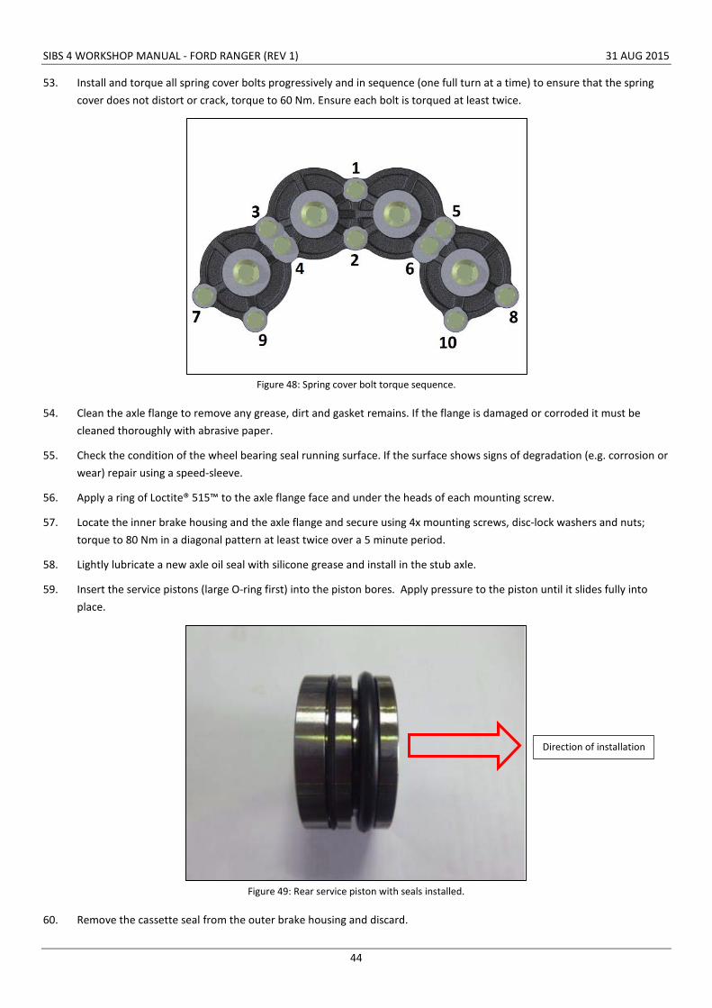
53. Install and torque all spring cover bolts progressively and in sequence (one full turn at a time) to ensure that the spring cover does not distort or crack, torque to 60 Nm. Ensure each bolt is torqued at least twice.
Figure 48: Spring cover bolt torque sequence.
54. Clean the axle flange to remove any grease, dirt and gasket remains. If the flange is damaged or corroded it must be cleaned thoroughly with abrasive paper.
55. Check the condition of the wheel bearing seal running surface. If the surface shows signs of degradation (e.g. corrosion or wear) repair using a speed-sleeve.
56. Apply a ring of Loctite® 515™ to the axle flange face and under the heads of each mounting screw.
57. Locate the inner brake housing and the axle flange and secure using 4x mounting screws, disc-lock washers and nuts; torque to 80 Nm in a diagonal pattern at least twice over a 5 minute period.
58. Lightly lubricate a new axle oil seal with silicone grease and install in the stub axle.
59. Insert the service pistons (large O-ring first) into the piston bores. Apply pressure to the piston until it slides fully into place.
Figure 49: Rear service piston with seals installed.
60. Remove the cassette seal from the outer brake housing and discard.
Direction of installation

SIBS 4 WORKSHOP MANUAL - FORD RANGER (REV 1) 31 AUG 2015
45
61. Clean the outer brake housing and inspect for damage or wear.
62. Install a new cassette seal into the outer brake housing.
63. Push the outer brake housing onto the hub.
64. Install the outer brake pads in the outer brake housing ensuring correct orientation.
65. Install the rotor onto the hub spline ensuring correct orientation (splines should be fully engaged).
66. Lightly lubricate a new housing O-ring with silicone grease (Parker Super O Lube recommended) and install in the groove around the circumference of the inner brake housing.
67. Install the inner brake pads in the inner brake housing ensuring correct orientation.
68. Carefully fit the outer brake housing, hub and rotor assembly to the inner brake housing. 2x guide pins may assist with fitment.
69. Fit the 12x housing bolts and torque to 50 Nm, ensure each bolt is torqued at least twice.
70. Fit the outer wheel bearing, locking plate and hub nut. Torque to 60 Nm.
71. Fill the cavity behind the V-lip seal with a high temperature bearing grease (Castrol LMX recommended) via the grease nipple located on the hub face. Do not over-grease the V-lip cavity.
72. Install the inner internal circlip in the hub.
73. Install a new O-ring on the axle shaft.
74. Apply a smear of grease to the splines of the drive adapter then install between the hub and axle.
75. Secure the drive adapter and hub using the 2x circlips.
76. Install the hub cap.
77. Remove the 4x retractor bolts from the spring cover.
78. Fit the pad wear indicator to the lowest piston:
a. Screw the pad wear indicator piston into the lowest piston thread and torque to 10 Nm.
b. Fit the stainless steel gland fitting over the piston and screw this into the spring cover.
c. Fit the stainless steel protective cover and fibre washer to the gland fitting.
d. Fit 3x supplied tapered plugs to seal the remaining holes in the spring cover. The hex sockets may be filled with silicon to aid future removal.
79. Remove the SIBS® cooling fluid fill plug.
80. Fill the SIBS® 4 brake unit with new SIBS® cooling fluid and refit the fill plug with a new copper washer. Approximately 1 litre of SIBS® cooling fluid is required per brake unit.
81. Repeat for the opposing brake unit.
82. Inspect all the park/emergency brake hydraulic hoses and replace as required.
83. Replace all rear breather hoses.
84. Replace the expansion chamber breather caps.
85. Flush the pump reservoir with new ATF Dexron III and then fill to level window.
86. Prime the SIBS® pump by running intermittently (no more than 10 seconds at a time) until full hydraulic pressure is reached and the motor stops running automatically.
a. To run the pump and release the EMMA™ brake, twist and release the red E-stop button.

SIBS 4 WORKSHOP MANUAL - FORD RANGER (REV 1) 31 AUG 2015
46
b. To release hydraulic pressure and engage the EMMA™ brake, press the red E-stop button.
c. While performing this priming process, ensure the EMMA™ reservoir is constantly topped up to prevent the pump from running dry.
87. Bleed the park/emergency brake system using the bleed screws on the rear brakes.
88. Remove any clamps on the rear service line.
89. Flush the master cylinder with DOT 4 brake fluid.
90. Bleed the rear service brake system of air.
91. Check that there are no leaks from the system.
92. Fit the wheels and wheel nuts; torque in a criss-cross pattern as per the Ford Ranger workshop manual (88.2 - 117.6 Nm).
93. Conduct a “vehicle pre-start check”.

SIBS 4 WORKSHOP MANUAL - FORD RANGER (REV 1) 31 AUG 2015
47
16. Troubleshooting 1. Problem
a. Possible cause
i. Solution
1. Fault light on SIBS® controller flashing.
a. 2x flashes then rest – low battery fault (below 11V)
i. Charge vehicle battery
ii. Fault will self-clear when battery voltage is above 11V
b. 3x flashes then rest – controller PCB too hot
i. Remove any sources of heat that could be causing the controller to overheat
ii. Fault will self-clear when the PCB temperature drops below a certain level.
c. 4x flashes then rest - park/emergency brake took too long to release – operation aborted.
i. Check pump reservoir level is not too low. If low check system for leaks.
ii. Possible air in system causing slow release. Bleed park/emergency brake system.
iii. Pump motor has is too hot and has lost effectiveness – allow to cool to ambient.
iv. Cycle ignition to clear the fault from the controller.
d. 5x flashes then rest – pump relay fault
i. Ensure wiring is not causing a short or open circuit to pump relay.
ii. Check pump relay for correct function – replace if required.
iii. Cycle ignition to clear the fault from the controller.
e. 6x flashes then rest – dump valve fault
i. Ensure wiring is not causing a short or open circuit to dump valve.
ii. Check dump valve for correct function – replace if required.
iii. Cycle ignition to clear the fault from the controller.
f. 7x flashes then rest – diff lock solenoid fault
i. Diff lock not fitted for Ranger – check for interference with 6 pin connector behind radio.
ii. Cycle ignition to clear the fault from the controller.
g. 8x flashes then rest – pressure sensor fault
i. Ensure wiring is not causing a short or open circuit to pressure sensor.
ii. Check pressure sensor for correct function – replace if required.
iii. Cycle ignition to clear the fault from the controller.

SIBS 4 WORKSHOP MANUAL - FORD RANGER (REV 1) 31 AUG 2015
48
2. ATF warning light on SIBS® controller on.
a. Vehicle parked on steep incline causing sensor to read incorrect fluid level.
i. Park vehicle on flat surface and check ATF warning light is off.
b. Low fluid level in SIBS® pump reservoir.
i. Top up reservoir with ATF Dexron III and check system for leaks.
3. Brake status LED is solid green and SIBS® controller is not responding.
a. Controller is in ‘SIBS® 3’ mode.
i. Conduct a master reset of the controller by holding the manual release button and cycling the E-stop button 3 times within 5 seconds. All lights on the controller will flash once to confirm reset was successful and all settings have been cleared.
4. Brake pedal soft/spongy
a. Air in the service brake system
i. Bleed the brakes
b. Brake rotors binding on splines
i. Crimp off brake hoses to isolate offending brake.
ii. Strip wheel end & inspect.
5. Brake pedal hard/excessive force required to operate brakes/reduced braking performance.
a. Pads and rotor surface glazed.
i. Change SIBS® cooling fluid and perform dry deglaze procedure if required.
b. SIBS® oil contaminated with brake fluid, ATF or grease.
i. Remedy any leaks then change SIBS® cooling fluid and perform dry deglaze procedure if required.
c. Vacuum system leak.
i. Inspect vacuum hoses, connections and booster for leaks.
6. Pedal goes slowly to floor with light application.
a. Master cylinder bypassing internally.
i. Strip and inspect. Replace cylinder or install overhaul kit.
b. Leak in brake lines/hoses or fittings.
i. Inspect brake lines and hoses for leaks.
ii. Ensure stainless fittings and bleed nipples are seated correctly. Tighten or replace as required.
c. Brake seals bypassing internally.
i. Strip brake and inspect service piston seals. Replace with new piston seal kit.

SIBS 4 WORKSHOP MANUAL - FORD RANGER (REV 1) 31 AUG 2015
49
7. Brakes drag/brakes not fully releasing after operation.
a. Booster/master cylinder out of adjustment.
i. Adjust booster output pushrod.
b. EMMA™ piston seals bypassing or service piston seals contaminated & swollen preventing them from retracting.
i. Locate which wheel end is affected (which wheel is dragging) or inspect rear brakes for ATF leakage around rear of spring cover.
ii. Strip brake, inspect components. Replace seals as required.
c. Insufficient hydraulic pressure to release EMMA™ brake.
i. Place vehicle on hoist and release EMMA™ brake. Check to see if one or both wheels are dragging.
ii. If both sides: Carryout pressure check in EMMA™ circuit, should be 850psi, if pressure is insufficient change pressure switch. If pressure still low, EMMA™ pump may be at fault.
iii. If only on one side: strip wheel-end & inspect.
8. Vehicle pulls to one side during braking.
a. Generally due to reduced effectiveness in one brake (brake steer). Vehicle will pull to the side with the more effective front brake. Usually caused by front brake issue.
i. If running OEM front brakes refer to Ford manual.
b. SIBS® oil contaminated with brake fluid, ATF or grease.
i. Remedy any leaks then change SIBS® cooling fluid and perform dry deglaze procedure if required.
9. Brakes shudder as vehicle slows to a stop.
a. Old/overused SIBS® oil.
i. Change SIBS® cooling fluid.
b. Brakes are cold.
i. Complete 3x medium/hard stops to warm brake.
ii. If shudder persists after more than first three brake applications, change SIBS® cooling fluid and perform dry deglaze procedure if required.
10. SIBS® park/emergency brake applies unexpectedly.
a. Faulty wiring causing intermittent loss of continuity.
i. Inspect/test 12 volt ignition switched & 12 volt constant supply. Ensure all connections are clean, secure and free of corrosion.
ii. Check door switches.
iii. Check seatbelt switches.
iv. Check oil-pressure switches.
11. SIBS® park/emergency brake is poor. Brake not holding on inclines.
a. Brake pads and/or rotor worn.
i. Check pad wear indicators. If pads below wear limit conduct a major service.
12. SIBS® park/emergency brake slow to apply

SIBS 4 WORKSHOP MANUAL - FORD RANGER (REV 1) 31 AUG 2015
50
a. Brake pads worn.
i. Check pad wear indicators. If pads below wear limit conduct a major service.
b. SIBS® relief valve set too high.
i. Adjust to desired application speed by loosening locknut and turning adjusting screw out. Adjust ½ turn at a time & test.
13. SIBS® pump runs intermittently during service (brake status light flashes red and beeps occasionally).
a. Minor leak in park/emergency brake system
i. Check all hydraulic hoses and connections for signs of leaking ATF.
ii. Strip brake and check emergency/park brake piston seals and bores. Replace as required.
14. Pump does not run (SIBS® park/emergency brake does not release).
a. Check interlocks are not preventing brake release
i. Close all doors, fasten driver’s seatbelt, start vehicle engine.
b. Loss of power to SIBS® controller (indicated by lack of brake status LED).
i. Check all fuses. If blown identify cause and repair.
c. Loss of power to SIBS® pump.
i. Check all fuses. If blown identify cause and repair.
ii. Check function of relay mounted at vehicle battery. Replace if required.
iii. Check for continuity of wiring from battery to pump motor and relay to controller.
d. Faulty pump motor.
i. Replace pump motor.


![Interface with SIBS-AT2 Oracle FLEXCUBE Universal … · Interface with SIBS-AT2 Oracle FLEXCUBE Universal Banking Europe Cluster Release 11.3.81.02.0 [October] [2013]](https://img.pdfslide.net/doc/110x75/5b02e1637f8b9a3c378b5b7a/interface-with-sibs-at2-oracle-flexcube-universal-with-sibs-at2-oracle-flexcube.jpg)