Embed Size (px)
Citation preview

pfa-inc.com
ZERO CORE MOVEMENT DURING INJECTION
SIDE-ACTION SYSTEMS
NOW WITHSWITCHMAX®
SENSOR CONNECTIVITY
WE TAKE MOVEABLE SLIDES AND CORES TO A NEW LEVEL OF PERFORMANCE
UPGRADE MACHINE PERFORMANCE & PROFITABILITY!
UPGRADE TO PFA!
Designed & Made in USA

Located just North of Milwaukee, Wisconsin, PFA is a
leader in the design and manufacture of Quick Die Change
Systems (QDC), Specialty Injection Mold Components,
Specialty Industrial Cylinders, Quick Mold Change
Systems (QMC), Multi-Slide Die Casting Solutions, and
Robotic Automation End-Effectors.
• SWITCHMAX® Connectivity Components and
Electrical Cables integrate various “on mold” sensors
(relay, mechanical, and proximity DC) into a single
signal interface common on most injection molding
machines. LED indication also assists operators. No
more complex wiring – just plug & play.
• Robotic Automation End Effectors. Modular products
allow the coupling of Grippers, Gripper Pads (GP),
Compliance Devices (RCC) and Crash Protection
(OPD) into a simple and integrated robotic end-effector
solution.
• Quick Die Change Systems provide easily customized
solutions for stamping die “quick change”. Bolster
extensions, die rails/lifters, check valve and locking
clamps, and electronic 5,000 psi pump controllers are
just a few of the options available.
• Hydra-Jaws™ Quick Mold Change and Hydra-
Latch™ Quick Knockout Systems provide consistent
clamping and support rapid mold changes for a wide
range of mold sizes in a single machine. Clamps move
to fit the mold!
• Self-Locking and Braking Cylinders hold large loads
many times that of standard cylinders, even with
pressure removed, making them ideal for a wide variety
of industrial applications, where large load capacity or
loss of air scenarios demand greater performance and
simplicity.
Our staff is committed to providing you with the best
possible products and service. PFA offers a wide array
of standard products plus custom solutions for especially
challenging applications. Contact us with your needs. We
will be glad to serve you!
N118 W18251 Bunsen Drive
Germantown, WI 53022
(262) 250-4410 • Fax (262) 250-4409
www.pfa-inc.com
2 KOR-LOK® SIDE ACTION SYSTEMS BY PFA, INC.
pfa-inc.com
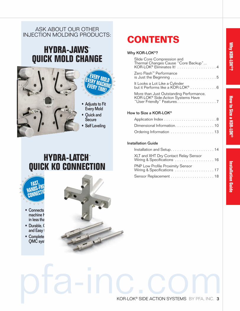
CONTENTSWhy KOR-LOK®?
Slide Core Compression and Thermal Changes Cause “Core Backup”... KOR-LOK® Eliminates It! . . . . . . . . . . . . . . . . . . 4
Zero Flash™ Performance is Just the Beginning . . . . . . . . . . . . . . . . . . . . . 5
It Looks a Lot Like a Cylinder but it Performs like a KOR-LOK® . . . . . . . . . . . . 6
More than Just Outstanding Performance, KOR-LOK® Side-Action Systems Have “User Friendly” Features . . . . . . . . . . . . . . . . . . 7
How to Size a KOR-LOK®
Application Index . . . . . . . . . . . . . . . . . . . . . . . . 8
Dimensional Information . . . . . . . . . . . . . . . . . . 10
Ordering Information . . . . . . . . . . . . . . . . . . . . 13
Installation Guide
Installation and Setup . . . . . . . . . . . . . . . . . . . . 14
XLT and XHT Dry Contact Relay Sensor Wiring & Specifications . . . . . . . . . . . . . . . . . . 16
PNP Low Profile Proximity Sensor Wiring & Specifications . . . . . . . . . . . . . . . . . . 17
Sensor Replacement . . . . . . . . . . . . . . . . . . . . 18
• Connects KO Bars to machine KO plate (butterfly) in less than one minute
• Durable, Compact, and Easy to Install
• Completes the QMC system
HYDRA-LATCH™ QUICK KO CONNECTION
FAST,
HANDS-FREE
CONNECTION
• Adjusts to Fit Every Mold
• Quick and Secure
• Self Leveling
EVERY MOLDEVERY MACHINEEVERY TIME!
HYDRA-JAWS™ QUICK MOLD CHANGE
ASK ABOUT OUR OTHER INJECTION MOLDING PRODUCTS:
Why KOR-LOK
®?How
to Size a KOR-LOK®
Installation Guide
KOR-LOK® SIDE ACTION SYSTEMS BY PFA, INC. 3

N E W “ P R O A C T I V E ” ( K O R - L O K® ) C O R E S L I D E P O S I T I O N I N G
PFA’s KOR-LOK® Side-Action Systems are specifically
designed to produce 10x the power of standard cylinders at
end of stroke to preload the core above the injection force
and then lock that force in place.
C O N V E N T I O N A L “ R E A C T I V E ” C O R E S L I D E P O S I T I O N I N G
Above is an example of a conventional side-action system.
A cam pin provides the means of movement and the heel
block “locks” the slide in the tool. This system “reacts” to
the pressure and thermal effects with the result that the
core face shows “backup”.
“Reactive” Method “Proactive” MethodCam Pins, Standard Locking
Cylinders, Cavity Locks, Heel Blocks, Hydraulic Cylinders
KOR-LOK®
Side-Action Systems
In the past, core applications required choosing the best
REACTIVE method available, reacting to force but not applying it.
If it’s not applied force, it’s not maintaining position.
KOR-LOK®’s PROACTIVE Technology™ and 100% applied force
provides you with the advantages of Zero Flash™,
Zero Flex™ performance.
Steel Compression: Physics dictates that a pressure force
applied to any material will cause compression. Without
the ability to easily measure it during loading, it is often
“invisible” to practical experience, leading to the false
assumption that steel, for example, is incompressible and
core dimensions will not change under load.
Thermal Variation: Physics dictates that temperature
changes will change the size of an object. Like compression,
temperature changes are less likely to be considered and
are difficult to measure. Initial reviews often assume that
temperature is not an issue.
Core Changes look like “Backup”: During injection, the
resulting changes from pressure and temperature often
cause the core length to decrease and the resulting core
face position to be “backed up” from the desired position.
These changes are “seen” on the part, as if the entire core
was “backing up”, when in fact the no load room temperature
timing was correct. Core face “backup” during injection may
be as much as .020” or more depending on mold geometry.
Attempting to compensate for compression and thermal effects with tryouts and “tweaking” can become time intensive, repetitive and very costly.
KOR-LOK® eliminates “core backup” by preloading the core above the force of injection.
KOR-LOK® COMPENSATES FOR: • CORE COMPRESSION • THERMAL VARIATION • ASSEMBLY TOLERANCES
FORCE
CORE SET
CORE CAPTURED
INJECTION
ZERO MOVEMENT - FULLY COMPENSATED
FORCE
CORE SET
CORE PRELOADED
INJECTION
CORE BACKUP
PRELOADCOMPRESSION
FORCE
CORE SET
CORE CAPTURED
INJECTION
ZERO MOVEMENT - FULLY COMPENSATED
FORCE
CORE SET
CORE PRELOADED
INJECTION
CORE BACKUP
PRELOADCOMPRESSION
SLIDE CORE COMPRESSION AND THERMAL CHANGES CAUSE “CORE BACKUP”… KOR-LOK® ELIMINATES IT!
WHY KOR-LOK?
4 KOR-LOK® SIDE ACTION SYSTEMS BY PFA, INC.

pfa-inc.com
PART DESIGN–
COMPLEX PARTS MADE EASY.
Core preload means your parts can be made easily with
tighter tolerances, perfect match lines, and clean beautiful
textures. The all-in-one system means cores can move at
any angle any time, eliminating barriers to many complex
parts. Specify PFA for design freedom. Indulge yourself.
MOLD DESIGN–
BOLT-ON ACTIONS SIMPLIFY THE MOLD.
PFA ‘s turn-key system not only makes any side-action
easy, it eliminates the “one off” design and manufacture of
side actions. Design it right the first time, every time with a
proven system that does the job better. Technical help is
available 24 hours a day and CAD files are just a click away.
Design it better and faster with KOR-LOK®.
MOLD BUILD–
MODULAR MEANS FASTER AND EASIER BUILDS.
Simplified mold geometries, better slide performance,
smaller mold bases, and independent slide movement, all
mean quicker mold builds and reduced tryout time. Faster
build times, fewer tryouts, and excellent part quality make
your molds more competitive.
PRODUCTION–
ACHIEVE THE LOWEST COST PER PART.
KOR-LOK® helps you run the best parts possible in the
smallest press possible. Ensure you produce the parts you
want, when you want them – reduced maintenance means
improved up-time, consistent quality means less scrap, and
reduced cost per part means more profit.
Radiator Components
Engine Components:Aluminum BlockAir Intake SystemTubing Fittings
Tires
Mirror Assemblies
Cross Ventilation
Instrument Panels
Exterior Door Handles
Coolers
Child Car SeatsCell Phone Components
Sun GlassesScuff Plates
Transmission Housings and Drive Train ComponentsExterior
Facia
Some parts manufactured using PFA products
ZERO FLASH™ PERFORMANCE IS JUST THE BEGINNING… WE’RE SAVING YOU TIME AND MONEY EVERY STEP OF THE WAY.
KOR-LOK® GIVES YOU:• Perfect Match Lines• Consistent Part Quality• Lower Mold Costs• Reduced Cost-Per-Part• Smaller Mold Bases• Greatly Reduced Wear• Reduced Spotting Time
• Quicker Mold Build• Simplified Part Design• Simplified Mold Design• Proven Design
Performance• Unlimited Slide Travel• Unrestricted Orientation
KOR-LOK®
SIDE-ACTION SYSTEMS
VS.TRADITIONAL SIDE-ACTION
SYSTEMS
Mold OPENCore Out
Mold CLOSEDCore OUT CAN’T DO IT!
Mold CLOSEDCore IN
Core PRE-LOADEDAgainst FULL
Injection PressureCAN’T DO IT!
THE ONLY WAY TO ACHIEVE TRUE ZERO FLASH RESULTS, PART AFTER PART, IS WITH – KOR-LOK® SIDE-ACTION SYSTEMS...
Why KOR-LOK
®?How
to Size a KOR-LOK®
Installation Guide
KOR-LOK® SIDE ACTION SYSTEMS BY PFA, INC. 5

HOW IT WORKS
KOR-LOK® Side-Action Systems provide large pre-loads and
thermal compensation to core slides by use of an internal
tapered locking mechanism. The threaded housing provides
a base to support the locking mechanism and transfer load
between the mold and the core slide, as follows:
SET The rod is extended using extend pressure. As the
rod nears end of stroke, the locking segments are
forced into the rod groove by hydraulic pressure on
the locking slide. As the segments are “squeezed,”
the rod is forced forward ensuring a positive seal on
the core face, while activating the sensor.
PULL Retract pressure releases the locking slide, allowing
the segments to disengage as the piston retracts.
When fully retracted, the rear sensor is activated,
indicating the slide is fully retracted.
Once set using only a minimum of 1,500 psi hydraulics,
KOR-LOK® Side-Action Systems provide 100% preload to
rated load - 10 times more force than a standard cylinder.
KOR-LOK® doesn’t just lock, it “super locks” by preloading
and locking in the force so hydraulics are no longer needed.
The result is 100% preload to rated load at zero pressure.
LockingSlide
Jam Nut
Core Slide
AlignmentScrew
Metal RodScraper Option
MountingFlange
LockingSegment
�readed Nose
AnnularGroove Extend Ports
AlignmentCoupler
LockingSensor
Retract Ports
IT LOOKS A LOT LIKE A CYLINDER BUT IT PERFORMS LIKE A KOR-LOK®!
PFA MEANS REAL SERVICEWith real-time information access, 24-hour technical support and expedited shipping, we can have a KOR-LOK® Side-Action System at your door often before you’ve had your morning coffee. That’s REAL SERVICE™.
NEED IT RIGHT NOW?Need same day or overnight shipping? We can do it!
HAVE AN EXISTING MOLD PROBLEM?We work with our customers to solve existing problems, and can design custom solutions, if necessary.
NO DELAYSWith a proven system, your mold works every time. Using a KOR-LOK® Side-Action System results in shorter design and manufacturing time, leading to shorter concept-to-production schedules.
Series Size Set Position* Output Force
75 12,000 lbs. (6 tons)100 26,000 lbs. (13 tons)112 40,000 lbs. (20 tons)150 60,000 lbs. (30 tons)200 110,000 lbs. (55 tons)300 210,000 lbs. (105 tons)
*Force ratings are at end of stroke only, based on assumed mold geometry. Ratings are for reference only. Actual performance will vary with application, setup and operating pressure.
6 KOR-LOK® SIDE ACTION SYSTEMS BY PFA, INC.

pfa-inc.com
• MULTIPLE PORTS - REAR PORTS STANDARD
While only two hydraulic ports are used, we provide 5
SAE ports for maximum flexibility. All ports are machined
in every unit. Using the two rear ports is quite popular.
• MULTIPLE SENSOR LOCATIONS AND GUARDS
STANDARD.
As sensor location may vary with adjusted preload
position, multiple front and rear sensor locations are
machined in every unit. Sensor guards are included to
protect your investment.*
• DIRECT WIRE RELAY OR PROXIMITY SENSORS
Embedded dry contact sensors (XLT & XHT) verify “set”
and “pull” positions without a voltage drop, making wiring
multiple sensors simple and easy.** Low Profile Proximity
Sensors (PNP) are also available.
• LARGE BORE CYLINDER OPTION
For deeply penetrating cores in high shrinkage materials,
we are pleased to recommend our “LB” option. By
adding a larger cylinder section to the standard fronts,
pull force is greatly increased for improved core pull. Die
casting materials and thermosets are typical material
applications.
• HIGH TEMPERATURE COMPONENTS/
METAL WIPERS
Flourocarbon seals (VI), Metal Wipers (MW), and High
Temperature Sensors (XHT) provide the enhanced
operating range for demanding environments to near 400˚F.
MULTIPLE SENSOR INTEGRATION WITH SWITCHMAX® SENSOR CONNECTIVITYEliminate wiring schematics and troubleshooting problems
on all molds.
SWITCHMAX® WITH PFA KOR-LOK® SIDE-ACTION SYSTEMS:
PFA’s new SWITCHMAX® components integrate multiple
KOR-LOK® unit sensors and other slide sensors into
single set and pull inputs to the press. When used with
KOR-LOK® XLT or XHT sensors and other Single Pole
Double Throw (SPDT) switches, the system provides cross
checking of proper sensor position, as well.
SWITCHMAX® WITH OTHER MECHANICAL SWITCHES:
Integrate almost ANY mechanical relay/dry contact switches
(plunger, rocker, PFA mechanical, relay) from multiple cores
to an operator side interface for simple one input connection
to the press. Full “plug and play” basic operation - NO
programming or dip switching required.
MORE THAN JUST OUTSTANDING PERFORMANCE, KOR-LOK® SIDE-ACTION SYSTEMS HAVE “USER FRIENDLY” FEATURES
* Due to its small size, the 75 series does not have guards.
** For crash condition cores, we recommend an additional redundant sensor on the core itself to verify core retraction in the event of core to KOR-LOK® separation or false sensor reading if damaged or contaminated.
SWITCHMAX® WITH 3 WIRE DC PROXIMITY SENSORS AND AC POWER CONTROLS:
SWITCHMAX® is also available in versions to integrate
PFA’s new Low Profile Sensor (PNP) and other 3 wire
PNP style switch sensors. For AC applications, the
addition of the SWITCHMAX® AC Power Adaptor allows
connection to machine controls operating with AC inputs.
Power Adaptors are also available for Ø Volt Input Injection
Molding machines.
Why KOR-LOK
®?How
to Size a KOR-LOK®
Installation Guide
KOR-LOK® SIDE ACTION SYSTEMS BY PFA, INC. 7

PERFORMANCE RATINGSKOR-LOK® load ratings are empirically derived from a
range of typical application geometries and mold behaviors.
Ratings should be used only with calculations using
maximum pressure and projected core area, as they already
take into account some limits on preload adjustment and
mold geometry, as well as cavity pressure drops, action
geometry, typical core lengths, etc.
Preload ratings apply to a well secured stiff mold geometry
with a core stroke of 5” or less, core lengths 5” or less,
and core areas equal to or greater than core projected area.
Basically, the load ratings apply to typical applications where
mounting is relatively close to the part. For longer cores, or
poor mounting support, it is highly recommended that the
next larger unit be considered.
PFA application specialists are available to discuss
recommendations, based on your particular application
and their experience. While form, fit, and function for any
particular application is the responsibility of the customer,
following PFA recommended sizing has shown to be the
best way to ensure optimal success.
SELECTING SERIES SIZEInjection pressure (P) for sizing calculations is the peak
pressure at the nozzle during the injection cycle, and
is a function of the injection screw piston area and
ram pressure. Typical Injection nozzle pressures are
approximately 10 times the hydraulic ram pressure shown
on the molding machine. Easy flow plastics typically run at
800 psi hydraulic x 10 = 8,000 psi, while high temperature
plastics or glass fill plastic applications may require 20,000
psi or more. Part geometries and minimum wall thickness
strongly affect the required processing pressures and thus
have a major impact on the series selection.
HOW TO SIZE
Projected core area (A) is the projected area along the axis
of movement wetted by plastic, including internal shutoff
areas. It may be most closely thought of as the area of
a slice through the core perpendicular to the core axis.
Calculation of the necessary Preload force becomes:
Minimum Preload Fore Rating (Ibs) = A (sq. in.) X P (psi).
The KOR-LOK® Side-Action System is typically chosen
with a rating above this force by some margin. For a free
application review please contact PFA, providing complete
details, such as Core Projected Area, Core Diameter, Core
Length, Stroke, Maximum Injection Pressure, Hydraulic
Pressure, Material Type, and 3D Drawings of the core/mold
arrangement, if possible.
STROKE TO INCLUDE ADJUSTMENTStroke is primarily determined by the need to clear the core
from the part, but practical efforts should be made to simplify
overall product selection, mounting, and adjustment. Detailed
information on a specific size can be downloaded with the
CAD file image on our website under KOR-LOK® > CAD Files.
Note that for non-integer strokes, we employ a “Variable E”
dimension (see dimensional data), such that a standard rod
of the next longer integer stroke is combined with the piston
tubes to match the desired stroke. The result is a change in
the chart “E” dimension.
During setup, the cylinder is advanced causing cylinder
stroke to be reduced by approximately .100”. Therefore,
approximately 1/8” should be added to the retract amount
needed to clear the part. Also ensure the cylinder is allowed
to stroke fully for proper sensor operation.
APPLICATION IDEAS & RECOMMENDATIONS
8 KOR-LOK® SIDE ACTION SYSTEMS BY PFA, INC.

pfa-inc.com
KOR-LOK® main unit. Use of the sensors during setup
and adjustment assists in verification of proper operation
(see pages 14-15). The SWITCHMAX® junction box and
cabling is recommended for multiple core applications,
crash condition cores, or when cross checking of sensor
positions or LED indication is desirable.
High Temperature Seals (VI), Metal Rod Wiper (MW)
and High Temperature Relay Sensor (XHT) options are
available for very high temperature plastic and die casting
environments. For some applications, insulation between the
flange and the mold (or flange cooling) may be needed.
DRIVING WEDGES AND RACKSBecause the KOR-LOK® generates preload though an
internal wedge style force intensifier, wedge applications
and rack and pinion designs often limit the ability for the
main unit to preload the core face.
For wedge applications, preloading the prime mover is
often enough to hold the core in position for successful
part production, however the core face itself is often not
substantially preloaded. As these applications are often
difficult in concept, use of the KOR-LOK® system can
provide substantial advantages, however, we recommend
careful PFA staff review.
Rack and Pinion applications typically have special challenges
with a large preload force applied to the gear teeth. Typically
the racks are not sized large enough to handle the forces
needed to transmit the preload to the core. Careful review
is recommended to determine feasibility.
PFA APPLICATION REVIEWMaking the difficult easy and successful is one of the great
advantages of the KOR-LOK® Side-Action System and
we are proud to back that up with the best in service and
support. For best results, please have a PFA application
specialist review your selection criteria to help ensure
nothing was missed. When it looks like a challenge, our
application specialists are on your side to find a way to
make the difficult easier. For the most detailed sizing
information, product specifications, design suggestions,
CAD files, and new product updates, call your application
specialist or visit us at www.pfa-inc.com.
MOUNTING OPTIONS – BOLT C’BORE & PARTING LINEUse of a mounting flange (RFC/SFC), jam nut (JN), alignment
screw (AS), and alignment coupler (AC) [or T-Slot in the core]
is standard on nearly every application to allow for proper
alignment and preload adjustment of the main unit cylinder.
Mounting distance from the core must account for the
variable E dimension for non-integer stroke units. Use of
integer stroke units is recommended for ease of design and
off the shelf delivery. Flanges can be mounted with counter
bored mounting bolts in locations desired by the customer, as
long as there is equal coverage
around the KOR-LOK®.
It is recommended that bolts be
located outside the diameter of
the jam nut for ease of removal
and that flanges be spaced off
from the mold to allow KL unit
to thread through the flange past
the flange face approximately
1/8” (or the mold relieved to
allow for preload adjustment).
If mounting the unit on the parting line, use a block to capture
one side of the flange in place of the mounting bolts. Call PFA
for mounting ideas and information regarding proper mold
sequencing for flange capture applications.
HIGH TEMPERATURE SEALS, WIPERS, AND SENSOR OPTIONSFront (set-locked-preloaded) and rear (pull) sensors
(switches) and cables are included with each
CLEARANCE
PARTING LINE
NOTE: it is recommended that themounting bolts are not blocked bythe jam nut, preventing removal
Provide counterbore clearance in mold for threading cylinder thru �ange during setup/adjustment
Flange mounting bolt, shown counterbored, see catalog for recommended bolt size, quantity and mounting pattern. Bolts must be counterbored to allow the use of the jam nut wrench
Why KOR-LOK
®?How
to Size a KOR-LOK®
Installation Guide
KOR-LOK® SIDE ACTION SYSTEMS BY PFA, INC. 9

M
C + STROKE
E A NO***
a
QI
R
P**
Alternate Set Sensor PortProvided in the event interference
occurs at �nal adjustment position
Alternate Pull Sensor PortProvided in the event interferenceoccurs with side sensor position
Pull Ports (3)
Set Ports (2)
M
C + STROKE
V
n
E A
I
R
a
N
Q
U
O***P**
Pull Ports (4)
Set Ports (3)
DIMENSIONAL INFORMATION(All Dimensions nominal and in inches)
KOR-LOK® SERIES SIZE: 75, 100, 112, 150, 200, 300
KOR-LOK® SERIES SIZE: 112-LB, 150-LB, 200-LB
NEW!3D Models and CAD files available in 150+ formats• Calculate Preload: Core Area x Max Injection Pressure = Force
Select Output Intensifier Force (Preload) > Force
• Adjust chosen stroke for Preload: Add .125” to stroke needed to clear part. Cylinder Stroke = Stroke to Clear + .125”
• Part Penetration and Shrink: Choose LB (Large Bore) option for extra pull as needed.
• Seal Selection: Choose High Temperature Seals VI if slide/mold exceeds 175˚F/80˚C.
• Sensor Selection Options: Relay Low Temp XLT , Relay High Temp XHT , Low Profile PNP (see pgs 16-17 for specification).
• High Temperature Sensors: Consider XHT option if temperature exceeds 175˚F/80˚C.
• Rotational Adjustment Clearance: Consider Low Profile PNP sensors with SWITCHMAX® for an easy alternative to XLT sensors.
• Multiple Cores/Slides: Consider SWITCHMAX® connectivity solution for single press input (easy interface) of set and pull.
• Crash Condition Cores: Consider -XLT or -XHT with SWITCHMAX® (cross check sensors) - sensor on core recommended.
See the PFA website for CAD MODELS by PARTsolutions. CAD Models are available in over 150 native and neutral CAD and graphic formats, versions and revisions. That means no matter what system your using, you can download KOR-LOK Models in your native format, which can be easily imported with all geometric integrity and meta data intact.“No other catalog provider offers as many CAD and graphic formats as PARTsolutions. Guaranteed.”
- Rob Zesch, President CADENAS PARTsolutions
Designed & Made in USA
10 KOR-LOK® SIDE ACTION SYSTEMS BY PFA, INC.

pfa-inc.com
M A I N U N I T [ K L H - _______- ( S T R O K E ) - O P T I O N S ]
Series Size
Output Intensifier Force**** (Preload)
Min. Pressure for Full Preload
Pressure to
Maintain Preload
Bore Dia. Rod Dia.
Extend Force
@1500psi
Retract Force
@1500psi A M E***RV I C
75 12,000 lbs. 1,500 psi 0 psi 1.25”0.75” 1,825 lbs 1,125 lbf 2 3/4”-16 0.75” 0.50” 2.25”
--- 3/8”-24 6.22”
100 26,000 lbs. 1,500 psi 0 psi 1.75”1.00” 3,600 lbs 2,425 lbf 3 1/2”-16 1.00” 0.50” 2.75”
--- 1/2”-20 7.26”
112 40,000 lbs. 1,500 psi 0 psi 1.75” 1.125” 3,600 lbs 2,100 lbf 3 1/2”-16 1.00” 0.50” 2.75”
--- 5/8”-18 7.26”
112-LB* 40,000 lbs. 1,500 psi 0 psi 3.00”1.125” 10,600 lbs 9,100 lbf 3 1/2”-16 1.00” 0.50” 2.75”
5.14” 5/8”-18 8.59”
150 60,000 lbs. 1,500 psi 0 psi 2.00”1.50” 4,700 lbs 2,050 lbf 4”-16 1.25” 0.75” 3.38”
--- 7/8”-16 8.93”
150-LB* 60,000 lbs. 1,500 psi 0 psi 4.00”1.50” 18,800 lbs 16,175 lbf 4”-16 1.25” 0.75” 3.38”
7.04” 7/8”-16 10.75”
200 110,000 lbs. 1,500 psi 0 psi 3.00”2.00” 10,600 lbs 5,850 lbf 5”-12 1.75” 1.00” 3.75”
--- 1 1/4”-12 9.98”
200-LB* 110,000 lbs. 1,500 psi 0 psi 5.50”2.00” 35,600 lbs 30,900 lbf 5”-12 1.75” 1.00” 3.75”
8.03” 1 1/4”-12 12.49”
300 210,000 lbs. 1,500 psi 0 psi 4.00”3.00” 18,800 lbs 8,225 lbf 6 3/4”-8 2.00” 1.25” 5.00”
--- 1 3/4”-12 12.08”
O U T E R D I M E N S I O N S , P O R T S A N D S E N S O R O P T I O N S
Series Size
Output Intensifier Force**** (Preload)
Body Dia. Nn
(SAE)
PNPLow Profile Prox
Original XLTRelay Low Temp
XHTRelay High Temp
a u O** P** Q** O** P** Q** O** P** Q**
75 12,000 lbs. 3.00 --- #4--- 4.8” 4.0” 0.5” 7.8” 7.1” 1.9” 9.3” 7.9” 2.7”
100 26,000 lbs. 4.00 --- #4--- 5.6” 5.1” 0.6” 8.4” 7.7” 2.1” 9.9” 9.2” 2.9”
112 40,000 lbs. 4.00 --- #4--- 5.6” 5.1” 0.6” 8.4” 7.7” 2.1” 9.9” 9.2” 2.9”
112-LB* 40,000 lbs. 4.00 6.00 #4#6 5.6” 6.9” 0.9” 8.4” 8.9” 2.3” 9.9” 10.4” 3.1”
150 60,000 lbs. 4.50 --- #6--- 6.1” 5.3” 0.9” 8.9” 7.9” 2.3” 10.4” 9.4” 3.1”
150-LB* 60,000 lbs. 4.50 7.50 #6#8 6.1” 8.1” 0.9” 8.9” 10.1” 2.3” 10.4” 11.6” 3.1”
200 110,000 lbs. 6.00 --- #6--- 7.0” 6.9” 0.9” 9.9” 8.9” 2.3” 11.4” 10.4” 3.1”
200-LB* 110,000 lbs. 6.00 9.00 #6#8 7.0” 9.5” 0.9” 9.9” 11.5” 2.3” 11.4” 13.0” 3.1”
300 210,000 lbs. 7.50 --- #8 --- 8.4” 8.1” 0.9” 11.3” 10.1” 2.3” 12.8” 11.6” 3.1”
*LB Option - Large Bore units have all the same accessories as standard units. Use -LB in the main unit order code only.
**Sensor Guard dimensions (for 75 series this is actual sensor height - no guards). O and P show swing arc clearance diameter during adjustment. Alternate front location included in the event that interference occurs at final adjustment position. Q is for alternate rear sensor position, if used in place of the rear side location (P).
***KL units use a “Variable E” dimension. Integer stroke lengths (1”, 2”, 3”, 4”, 5” standard) are available with E shown in chart. For non-integer fractional strokes, the E will vary from chart - longer by unused fraction of stroke.
****Output Mechanical Intensifier Ratings are for end of stroke (general reference only). Actual performance is dependent upon application geometry, setup and adjustment. Mid stroke and pull forces are less. Minimum operating pressure is 1,500psi to set with full rated preload. After locking, preload is maintained with 0 psi, hydraulics are NOT required to maintain lock.
NEW! NEW!
Why KOR-LOK
®?How
to Size a KOR-LOK®
Installation Guide
KOR-LOK® SIDE ACTION SYSTEMS BY PFA, INC. 11
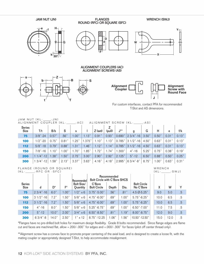
F L A N G E ( R O U N D O R S Q U A R E ) W R E N C H [ K L - _______- R F C O R - S F C ] [ K L - _______- S W J ]
Series Size d D* F*
RecommendedBolt Size/Quantity
Recommended Bolt Circle with C’Bore SHCS
Bolt CircleNo C’Bore X W Y
C’Bore Bolt Circle Depth Dia.
75 2 3/4”-16 6.0” 1.00” 1/2” x 6 3.75”-5.00” .56” .81” 4.5 Ø-5.25” 9.0 5.0 .5
100 3 1/2”-16 7.2” 1.50” 5/8” x 6 4.75”-6.00” .69” 1.00” 5.75”-6.25” 10.0 6.5 .5
112 3 1/2”-16 7.2” 1.50” 5/8” x 6 4.75”-6.00” .69” 1.00” 5.75”-6.25” 10.0 6.5 .5
150 4”-16 8.0” 1.50” 5/8” x 6 5.25”-6.75” .69” 1.00” 6.50”-7.00” 11.0 7.5 .5
200 5”-12 10.0” 2.00” 3/4” x 6 6.50”-8.50” .81” 1.19” 8.00”-8.75” 12.0 9.0 .5
300 6 3/4”-8 14.0” 2.50” 1” x 12 8.75”-12.25 1.06” 1.56” 10.50”-12.50” 15.0 12.0 .5
*Flanges have no pre-drilled bolt holes for maximum design flexibility. Grade 8 bolts recommended. Since flange edges are flame cut and faces are machined flat, allow +.200/-.000” for edges and +.000/-.300” for faces (pilot off center thread only).
**Alignment screw has a convex face to promote proper centering of the axial load, and is designed to create a loose fit, with the mating coupler or appropriately designed T-Slot, to help accommodate misalignment.
J A M N U T [ K L - ______- J N ]A L I G N M E N T C O U P L E R [ K L - _______- A C ] A L I G N M E N T S C R E W [ K L - _______- A S ]
Series Size T/t B/b S s I Z (set)
Z (pull) J** g G H e f/k
75 3/8”-24 0.57” .56” 1.00” 1.13” 0.91” 0.93” 0.690” 2 3/4”-16 3.50” 0.50” 0.31” 0.13”
100 1/2”-20 0.75” 0.81” 1.25” 1.375” 1.10” 1.13” 0.785” 3 1/2”-16 4.50” 0.63” 0.31” 0.13”
112 5/8”-18 0.79” 0.88” 1.31” 1.46” 1.12” 1.14” 0.785” 3 1/2”-16 4.50” 0.63” 0.31” 0.13”
150 7/8”-16 1.10” 1.00” 1.70” 1.85” 1.72” 1.74” 1.300” 4”-16 5.25” 0.75” 0.38” 0.19”
200 1 1/4”-12 1.38” 1.50” 2.75” 3.00” 2.90” 2.92” 2.125” 5”-12 6.50” 0.88” 0.50” 0.25”
300 1 3/4”-12 1.58” 2.13” 3.37” 3.63” 4.16” 4.18” 2.995” 6 3/4”-8” 8.75” 1.00” 0.63” 0.31”
Z
J
Bb
AlignmentScrew withRound Face
AlignmentCoupler
l
t T
Ss
Z
J
Bb
AlignmentScrew withRound Face
AlignmentCoupler
l
t T
Ss
e Hf
30°k
g GD
d
FX
W
Y
WRENCH (SWJ)JAM NUT (JN)
ALIGNMENT COUPLERS (AC) ALIGNMENT SCREWS (AS)
FLANGES ROUND (RFC) OR SQUARE (SFC)
For custom interfaces, contact PFA for recommended T-Slot and AS dimensions.
12 KOR-LOK® SIDE ACTION SYSTEMS BY PFA, INC.

pfa-inc.com
EXAMPLE:
Main unit and mounting accessory example for a large bore
150 series. Note that LB is only used for the main unit as
150-LB and 150 units have common accessories:
QUANTITY PART NUMBER
1 KLH-150-LB-XLT-3.00 Main Unit
1 KL-150-SFC Square Flange
1 KL-150-JN Jam Nut
1 KL-150-AS Alignment Screw
1 KL-150-AC Alignment Coupler
1 KL-150-SWJ Spanner Wrench
1 SM-KL-DCPKG-1S SWITCHMAX® Wiring
To test sensors of complete
installations a SWITCHMAX®
test box is available.
Part No. SM-RTB-1A
Example: KOR-LOK® Accessories
Series Size Accessories
75, 100, 112, 150, 200, 300
Round Mounting Flange = RFCSquare Mounting Flange = SFC
Jam Nut = JNAlignment Screw (Rod Interface) = AS
Alignment Coupler (Core Interface) = ACSpanner Wrench for Jam Nut = SWJ
KL 150 JN
KOR-LOK® Accessory Part No: KL-150-JN
Example: SWITCHMAX®
Sensor Wattage No. of Cylinders
XLT or XHT = KLPNP = PNP
110/115/AC = ACPKG24VDC = DCPKG
1 = 1S; 2 = 2S, etc
SM KL DCPKG XX
SWITCHMAX® Part No: SM-KL-DCPKG-1S
Example: KOR-LOK® Main Unit
Series Size Stroke (inches) Sensor Options (only if needed)
75, 100, 112, 112-LB, 150, 150-LB, 200, 200-LB, 300
Choose stroke to allow for preload adjustment.
Standard Relay (Low Temp) = XLTRelay High Temp = XHTLow Profile PNP = PNP
Metal Wiper = MW High Temp Seals = VI
KLH 150-LB 3.00 XLT MW VI
Main Unit Part No: KLH-150-LB-3.00-XLT-MW-VI
JUNCTION BOX GENERAL SPLITTER CABLE LAYOUT
SWITCHMAX® (OPTIONAL)
DATE
CO
DE
TM
Junc
tionB
ox
Why KOR-LOK
®?How
to Size a KOR-LOK®
Installation Guide
KOR-LOK® SIDE ACTION SYSTEMS BY PFA, INC. 13
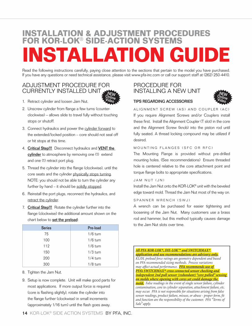
ADJUSTMENT PROCEDURE FOR CURRENTLY INSTALLED UNIT
1. Retract cylinder and loosen Jam Nut.
2. Unscrew cylinder from flange a few turns (counter-
clockwise) – allows slide to travel fully without touching
stops or shutoff.
3. Connect hydraulics and power the cylinder forward to
the extended/locked position – core should not seal off
or hit stops at this time.
4. Critical Step!!! Disconnect hydraulics and VENT the
cylinder to atmosphere by removing one (1) extend
and one (1) retract port plug.
5. Thread the cylinder into the flange (clockwise), until the
core seats and the cylinder physically stops turning.
NOTE: you should not be able to turn the cylinder any
further by hand – it should be solidly stopped.
6. Reinstall the port plugs, reconnect the hydraulics, and
retract the cylinder.
7. Critical Step!!! Rotate the cylinder further into the
flange (clockwise) the additional amount shown on the
chart below to set the preload:
Series Pre-load75 1/6 turn100 1/6 turn112 1/6 turn150 1/3 turn200 1/4 turn300 1/8 turn
8. Tighten the Jam Nut.
9. Setup is now complete. Unit will make good parts for
most applications. If more output force is required
(core is flashing slightly), rotate the cylinder into
the flange further (clockwise) in small increments
(approximately 1/16 turn) until the flash goes away.
INSTALLATION & ADJUSTMENT PROCEDURES FOR KOR-LOK® SIDE-ACTION SYSTEMS
INSTALLATION GUIDERead the following instructions carefully, paying close attention to the sections that pertain to the model you have purchased. If you have any questions or need technical assistance, please visit www.pfa-inc.com or call our support staff at (262) 250-4410.
All PFA KOR-LOK®, DIE-LOK™ and SWITCHMAX® application and use recommendations are advisory only. KL/DL preload force ratings are geometry dependent and based on PFA recommended sizing methods. Process variations may affect actual performance. PFA recommends use of PFA’s SWITCHMAX® cross connected sensor checking and independent 2nd pull sensor (redundant) “core pulled” sensing on molds where opening with cores set could damage the mold. False readings in the event of single sensor failure, cylinder contamination, core to cylinder separation, attachment failure, etc. may occur. PFA is not responsible for situations arising from false sensor readings, product failure, misuse, or abuse - proper form, fit and function are the responsibility of the customer. PFA “Terms of Sale” apply.
PROCEDURE FOR INSTALLING A NEW UNIT
TIPS REGARDING ACCESSORIES
A L I G N M E N T S C R E W ( A S ) A N D C O U P L E R ( A C )
If you require Alignment Screws and/or Couplers install
these first. Install the Alignment Coupler (T slot) in the core
and the Alignment Screw (knob) into the piston rod until
fully seated. A thread locking compound may be utilized if
desired.
M O U N T I N G F L A N G E S ( S F C O R R F C )
The Mounting Flange is provided without pre-drilled
mounting holes. (See recommendations) Ensure threaded
hole is centered relative to the core attachment point and
torque flange bolts to appropriate specifications.
J A M N U T ( J N )
Install the Jam Nut onto the KOR-LOK® unit with the beveled
edge toward mold. Thread the Jam Nut most of the way on.
S P A N N E R W R E N C H ( S W J )
A wrench can be purchased for easier tightening and
loosening of the Jam Nut. Many customers use a brass
rod and hammer, but this method typically causes damage
to the Jam Nut slots over time.
NEW Online Video
NEW Online Video
14 KOR-LOK® SIDE ACTION SYSTEMS BY PFA, INC.

pfa-inc.com
PREPARATION FOR INSTALLATION OF THE MAIN UNIT – ON THE BENCH
1. Remove port plugs from one extend and retract port.
There are three options for the retract port (A, B and
C) and two options for the extend port (D and E) as
shown in Figure 1.
CAUTION! Fluid may eject from retract port as rod extends.
Observe proper safety precautions.
2. Apply a pressure source (minimum of 80 psi pneumatic
or hydraulic) to the open extend port (D or E) until the
unit is fully extended/locked.
INSTALLATION OF MAIN UNIT.
1. With the unit extended/locked, and vented (port plugs
removed on one (1) extend and one (1) retract port),
connect the core slide to the rod and thread unit into the
flange a few turns.
NOTE: For long term ease of adjustment, application of
anti-seize or other thread lubricant may be desired.
2. Thread unit inward (clockwise) until the core is fully
seated and cannot be turned in by hand – solidly
stopped.
3. Ensure proper thread engagement of the cylinder and
flange - equivalent to the thickness of the flange.
4. Ensure that there is space beyond flange for unit to
thread through for adjustment. See required flange
thickness for your model size (refer to “Recommended
Accessories” section of catalog).
5. Place mark on flange and unit body to mark position
location for reference.
6. Reinstall the port plugs, reconnect the hydraulics, and
retract the cylinder.
7. Thread the unit Inward (clockwise) the recommended
pre-load amount in the chart below.
Series Pre-load75 1/6 turn100 1/6 turn112 1/6 turn150 1/3 turn200 1/4 turn300 1/8 turn
8. Tighten Jam Nut.
9. Connect sensors using appropriate procedures for
the style utilized in your application. Documentation is
provided separately.
10. Extend unit HYDRAULICALLY (1500 psi minimum) and
verify lock sensor activates (turns on) ensuring unit
locks as expected. Failure to lock is one indication of
an adjustment problem.
11. After extending and locking, the preload stretches the
large threads which may cause loosening of the Jam
Nut. Re-tighten the jam nut, if desired.
(NOTE: If the jam nut is tightened while the unit is
preloaded, future loosening of the jam nut will require
extending and preloading the unit).
12. Cycle unit hydraulically several times and verify
complete operation.
13. Test Mold during injection and note part quality.
If flash occurs, additional preload adjustments
(1/16 turn increments clockwise) may be needed at
normal operating temperature to achieve the desired
final adjustment. If unit does not operate as intended,
call PFA for assistance. Applications vary widely and
this procedure may not exactly cover all geometries.
24/7 technical phone assistance is generally available.
These procedures have been written in an effort to address as many configurations as possible. If your particular application
requires set up procedures that are not covered in the preceding documentation, please contact PFA at (262) 250-4410
for assistance.
Why KOR-LOK
®?How
to Size a KOR-LOK®
Installation Guide
KOR-LOK® SIDE ACTION SYSTEMS BY PFA, INC. 15

PFA Relay-style sensors (CT70300 assembly
CT70520/21/22... High Temperature Assembly) function as
a true dry contact switch. In normal usage, when the target
comes “in range” of the sensor, the magnet inside the
switch closes a contact to complete the circuit.
CT70300 ASSEMBLY SPECIFICATIONSPart No. on Sensor: EE70194
Cylinder Designation: -XLT
Contact Type: SPDT (Single-Pole, Double Throw)
Contact Rating: 2 Amps @ 12OVAC 1 Amp @ 240VAC 1 Amp @ 24VDC
Temperature: -40˚F (-40˚C) to 257˚F (125˚C)
Pressure: 3000 psi max.
Install Torque Max.: 50 in-lbs. max.
CT70520/21/22... ASSEMBLY SPECIFICATIONSPart No. on Sensor: 72-16222-F4
Cylinder Designation: -XHT
Contact Type: SPDT (Single-Pole, Double Throw)
Contact Rating: 4 Amps @ 12OVAC 2 Amp @ 240VAC 3 Amp @ 24VDC
Temperature: -40˚F (-40˚C) to 400˚F (204˚C)
Pressure: 3000 psi max.
Install Torque Max.: 50 in-lbs. max.
Relay-style switches offer many benefits to the user. They
have no voltage drop when closed nor do they have leakage
current when open. In most applications the Normally Open
(N/O) connection is used so that when the cores reach
set or pull, the relay contacts close to give that indication
to the press. In most cases, the Normally Closed (N/C)
connection is not used, but is available for use as part of PFA’s
SWITCHMAX® Mold Wiring solution.
Connection between the KOR-LOK® Side-Action System and
the press, is as simple as connecting two set sensor wires
and two pull sensor wires to the two pair of machine control
wires. The order of connection for each pair is not important.
Multiple set sensors may be wired in series to provide a single
set indication to the press. Similarly, the pull wires may be
connected in series. For situations where a core or other part
of the mold may be damaged if opened with cores set, it is
recommended that a redundant sensor be placed on the core
itself and wired in series with the main unit sensors to ensure
the core is retracted prior to mold opening.
PFA’s SWITCHMAX® Mold Wiring solution is also available
to provide cross checking of sensors to verify proper
sequencing and provide operator side LED light indication.
For additional information on SWITCHMAX®, please view the
information online at www.pfa-inc.com.
PIN 3NORMALLY OPEN
If target is atsensor (turned on)
resistance is lowbetween pins 1 & 3
PIN 1COMMON
PIN 2NORMALLY CLOSED
FROMPRESSFRONT (SET) SENSOR
SET SENSOR #1
SET SENSOR #2
N/O(RED w/WHITE or BLUE)
N/C(RED w/BLACK or RED)
COMMON(GREEN or BLACK)
– to press set signal wire
RED w/WHITE Stripe or BLUE if High Temp signal to press
GREEN or BLACKif High Temp
RED w/WHITE Stripe or BLUE
GREEN or BLACK SETWIRE
signal from press
– NOT USED
– to press set signal wire
Fig. 1 - Single Sensor Wiring Fig. 2 - Multiple Sensor Wiring (Series)
XLT AND XHT PFA DRY CONTACT/RELAY SENSORSSENSOR WIRING AND REPLACEMENT INSTRUCTIONS Standard EE 70194/CT70300 (assembly) and High Temperature EE70199/CT705XX (Assemblies)
16 KOR-LOK® SIDE ACTION SYSTEMS BY PFA, INC.

pfa-inc.com
PFA Low Profile -PNP sensors (EE 70600/CT 70600
assembly with seal) function as typical high pressure
proximity sensor, with a solid state device that senses the
metal target of the lock or piston and outputs the input
voltage (24VDC) to the machine control.
CT70600 ASSEMBLY SPECIFICATIONSPart No. on Sensor: PFA-EE70600
Cylinder Designation: -PNP
Contact Type: Solid State PNP/NO
Contact Rating: 100 mAmps @ 24VDC
Supply Voltage: 10-30 VDC
Voltage Drop: ≤2.5 VDC
Temperature: -13˚F (-25˚C) to 175˚F (80˚C)
Install Torque Max.: 50 in-lbs. max.
Low Profile PNP sensors offer benefits to the user when
fitting The KOR-LOK unit into demandingly small applications
or when Integrating with other actuators using similar PNP
sensor logic. PFA’s PNP option has a low voltage drop,
typically allowing multiple sensors to be connected together
to facilitate a single input to the machine control. Sensor
integration is easily accomplished with PFA’s SWITCHMAX®
connectivity solution with PNP designated splitter cables.
In a generic application the Normally Open Sensor is paired
with an individual cable to provide power and route the
signal. To use the sensors individually, Power +24VDC
(Brown wire) and Neutral 0 VDC (Blue wire) is required, as
well as some method of integrating the sensor signal (Black
wire) to the press. Various schemes are used to accomplish
this task for molds with multiple cylinders, however, PFA
recommends SWITCHMAX® to provide a plug and play
serial connection of sensors into single inputs for set
and pull, while also providing operator side indication and
troubleshooting capability.
While proper indication is expected, PFA cautions that for
situations where a core or other part of the mold may be
damaged if opened with cores set, it is recommended that
a redundant sensor be placed on the core itself and wired
in series with the main unit sensors to ensure the core is
retracted prior to mold opening.
For details on SWITCHMAX® options, please view the
information online at www.pfa-inc.com.
Example: Front (Set) Sensor
PNP LOW PROFILE PFA PROXIMITY SENSORSSENSOR WIRING AND REPLACEMENT INSTRUCTIONS EE70600/CT70600 Assembly
1 = Brown (Power + 24 VDC)2 = Blue (Neutral 0 VDC)3 = Black (Signal)
1
3
2
Why KOR-LOK
®?How
to Size a KOR-LOK®
Installation Guide
KOR-LOK® SIDE ACTION SYSTEMS BY PFA, INC. 17

SENSOR REPLACEMENTRead instructions completely before beginning work. If you
have questions or need technical assistance, please contact
PFA for support.
WARNING! The sensor is not solid metal! Torque values are very low - in-lb not ft-lb!
The XLT Relay Sensor Assembly consists of the Sensor
Body (EE70194), O-Ring Seal (2-013), and purple Loctite®
(#545) thread compound. The Loctite® is provided to give the
sensor resistance to loosening/leakage under normal use.
The XHT (High Temperature) Relay Sensor Assembly
consists of the Sensor Body (EE70199), High Temp (VI)
O-Ring Seals, Adaptor Body (LR08100) and purple Loctite®
thread compound.
The PNP (Low Profile) Solid State Sensor Assembly
consists of the Sensor Body (EE70600), O-Ring Seal
(2-013) and purple Loctite® thread compound.
PREPARATION FOR SENSOR REPLACEMENTEnsure all hydraulic pressure is removed from the unit.
Hoses may then be disconnected or the associated hydraulic
system vented and secured to prevent pressurization of the
KOR-LOK® Side-Action System Main Unit.
CAUTION!Fluid may eject from the sensor hole or ports under pressure or rod
movement. Sensor is capable of handling Large Voltage and Current levels. Observe proper safety precautions.
Ensure the main unit is in a safe orientation so that the rod
cannot move or apply a load on the cylinder, which might
result in applied pressure to fluid still inside the unit.
Disconnect or secure power to the sensor from associated
equipment.
REMOVAL OF OLD SENSORWith pressure removed and vented and electrical power
secured to the sensors, locate the front or rear sensor,
as appropriate. Remove the cable from the sensor by
unscrewing the retaining ring in a counterclockwise direction
and unplugging the cable. For direct wire -XHT sensors,
disconnect from power or controls.
Remove the sensor by rotating or unscrewing with a
counterclockwise rotation on the hex nut connector (a 5/8”
deep wall socket is recommended to avoid damage to the
connector plug for XLT sensors). For PNP sensors, use a
5/8” or 16mm socket with cutout for cable.
INSTALLATION OF NEW SENSOR(RECOMMENDED PREFERRED METHOD)
Inspect the sensor hole and surrounding sealing surface.
Remove any debris from the surface, degrease threads, and
ensure the surface is not damaged.
CAUTION! Sensor is designed to seal finger tight.
Do not exceed 50 in-lbs (inch-pounds) of torque.
Degrease threads in housing and sensor. Ensure threads
are clean and dry. If available, apply Loctite® Locquic®
Primer T (7471) or equivalent to threads and wait until dry.
Add a small drop of purple Loctite® (#545) to the sensor
threads and insert the new sensor in the hole turning
clockwise. (Turn the sensor using fingers only until
resistance of the o-ring seal is encountered - continue
turning sensor clockwise against the seal resistance until
the sensor seats on the sealing surface). The o-ring will
seat with minimal torque and is fully seated by 30 in-lbs. At
this level the sensor no longer turns freely.
Torque to 45 in-lbs (a 5/8” deep wall socket is recommended
to avoid damage to the connector plug). EXCESSIVE
TORQUE WILL DAMAGE THE SENSOR.
Connect cable and turn the connector retaining ring
clockwise until play is removed or reconnect wiper as
appropriate.
Allow Loctite® to set for 5 minutes and reinstall KOR-LOK®
unit in mold.
All PFA KOR-LOK®, DIE-LOK™ and SWITCHMAX® application and use recommendations are advisory only. KL/DL preload force ratings are geometry dependent and based on PFA recommended sizing methods. Process variations may affect actual performance. PFA recommends use of PFA’s SWITCHMAX® cross connected sensor checking and independent 2nd pull sensor (redundant) “core pulled” sensing on molds where opening with cores set could damage the mold. False readings in the event of single sensor failure, cylinder contamination, core to cylinder separation, attachment failure, etc. may occur. PFA is not responsible for situations arising from false sensor readings, product failure, misuse, or abuse - proper form, fit and function are the responsibility of the customer. PFA “Terms of Sale” apply.
18 KOR-LOK® SIDE ACTION SYSTEMS BY PFA, INC.

pfa-inc.com
Why KOR-LOK
®?How
to Size a KOR-LOK®
Installation Guide
KOR-LOK® SIDE ACTION SYSTEMS BY PFA, INC. 19

N118 W18251 Bunsen Drive Germantown, WI 53022
(262) 250-4410Fax (262) 250-4409
pfa-inc.comCopyright ©2014 PFA, Inc. All rights reserved. Reproduction or use in any manner of editorial or graphic content herein without the express written permission of PFA, Inc. is strictly prohibited. Every effort has been made to ensure the information within this publication is complete and accurate at the time of printing.
YOUR LOCAL PFA REPRESENTATIVE:
S2508 REV C