Embed Size (px)
Citation preview
FX3Uシリーズマイクロシーケンサ
ハードウェアマニュアル
このたびは、本製品をお買い上げいただき、誠にありがとうございました。
本マニュアルは、FX3Uシリーズシーケンサ(基本ユニット)の各部名称、外形寸法、取付け、および配線についてFX3Uユーザーズマニュアル[ハードウェア編]から抜粋したものです。詳細につきましては、FX3Uユーザーズマニュアル[ハードウェア編]をご覧ください。ご使用の前に、FX3Uユーザーズマニュアル[ハードウェア編]および関連製品マニュアルをお読みいただき、機器の知識、安全の情報、注意事項のすべてについて習熟してからご使用ください。また、製品に付属しているマニュアルは必要なときに取り出して読めるように大切に保管すると共に、必ず最終ユーザまでお届けいただきますようにお願いいたします。商標について本マニュアルに記載してある会社名,製品名は、それぞれの会社の登録商標または商標です。
この印刷物は2015年4月発行です。なお、お断りなしに仕様を変更することがありますのでご了承ください。
© 2013 Mitsubishi Electric Corporation
安全上のご注意 (ご使用の前に必ずお読みください)
このマニュアルでは、安全に関する注意事項のランクを
、 として区分してあります。
なお、 に記載した事項でも、状況によっては重大な結果に結
びつく可能性があります。いずれも重要な内容を記載していますので必ず守ってください。
マニュアル番号 JY997D50301
副番 B
製作年月 2015年4月
取り扱いを誤ったばあいに、危険な状況が起こりえて、死亡または重傷を受ける可能性が想定されるばあい。
取り扱いを誤ったばあいに、危険な状況が起こりえて、中程度の傷害や軽傷を受ける可能性が想定されるばあい、および物的損害だけの発生が想定されるばあい。
立上げ・保守時の注意
通電中には端子に触れないでください。感電の恐れや、誤動作の原因となることがあります。
清掃および端子の増締めは、必ず電源を外部にて全相遮断してから行ってください。通電中に行うと感電の恐れがあります。
運転中のプログラム変更,強制出力,RUN,STOPなどの操作はマニュアルを熟読し、十分に安全を確認してから行ってください。操作ミスにより機械の破損や事故の原因となることがあります。
シーケンサ内のプログラムは、複数の周辺機器(プログラミングツールやGOT)から同時に変更しないでください。シーケンサのプログラムが壊れたり、誤動作する恐れがあります。
メモリバックアップ用バッテリは「FX3Uユーザーズマニュアル[ハードウェア編]」に定められた内容に従って、正しく使用してください。- 定められた用途以外に使用しないでください。- 正しく接続してください。- 充電,分解,加熱,火中投入,ショート,逆接続,ハンダ付け,飲
み込む,焼却,過度の力(振動・衝撃・落下など)を加えるなどを行わないでください。破裂や発火の恐れがあります。
- 高温保存,直射日光にさらされる場所での保存や使用は避けてください。
- 漏液などの内容物を水にさらす,火気に近づける,直接触れるなどは行わないでください。
- バッテリの取扱いを誤ると、過度な発熱,破裂,発火,燃焼,漏液,変形などにより、ケガなど人体への影響や、火災,設備・他機器などの故障や誤動作の原因となる恐れがあります。
立上げ・保守時の注意
メモリカセットを脱着するときは必ず電源を切ってください。通電中に脱着するとメモリの内容や、メモリカセットを損傷することがあります。
分解,改造はしないでください。故障,誤動作,火災の原因となることがあります。*修理については、三菱電機システムサービス株式会社にお問
い合わせください。 増設ケーブルなどの接続ケーブルの着脱は電源をOFFしてから
行ってください。故障,誤動作の原因となることがあります。
下記の機器を脱着するときは必ず電源をOFFしてください。故障,誤動作の原因となることがあります。- 周辺機器,ディスプレイモジュール,機能拡張ボード- 増設ユニット/ブロック,特殊アダプタ- バッテリ,メモリカセット
廃棄時の注意
製品を廃棄するときは、産業廃棄物として扱ってください。バッテリを廃棄する際には各地域にて定められている法令に従い分別を行ってください。
(EU加盟国内でのバッテリ規制についての詳細は「FX3Uユーザーズマニュアル[ハードウェア編]」を参照してください。)
関連マニュアルとマニュアルの入手方法
関連マニュアルFX3Uシリーズ シーケンサ(基本ユニット)には、本書(ハードウェアマニュアル)を同梱しています。FX3Uシリーズのハードウェアに関する詳細説明、シーケンスプログラミングのための命令解説, 特殊増設などの情報はそれぞれの資料をご覧ください。
輸送・保管上の注意
シーケンサを輸送するばあい、必ず輸送前にシーケンサに電源を投入し、「BATTのLEDがOFFしていること」と「バッテリの寿命」を確認してください。BATTのLEDがONしている状態や寿命を過ぎている状態で輸送を行うと、輸送中にバックアップしているデータを正しく保持できないことがあります。
ユニットは精密機器のため、輸送の間2.1節に記載の一般仕様の値を超える衝撃を避けてください。ユニットの故障の原因になることがあります。輸送後、ユニットの動作確認を行ってください。
リチウムを含有しているバッテリの輸送時には、輸送規制に従った取扱いが必要となります。
(規制対象機種についての詳細は「FX3Uユーザーズマニュアル[ハードウェア編]」を参照してください。)
マニュアルの入手方法
マニュアルの入手方法には、下記の方法があります。1) 製本マニュアル(印刷物)の入手
本製品のご購入店へお問い合わせください。2) 電子データ(PDFファイル)の入手
インターネットサイト(三菱電機FAサイト)から最新マニュアルをダウンロードできます。ホームページ 三菱電機FAサイトhttp://www.MitsubishiElectric.co.jp/fa
マニュアル名称 マニュアル番号 内容
FX3Uユーザーズマニュアル
[ハードウェア編]
JY997D16101[別冊]
形名コード:09R515
FX3U シリーズシーケンサ本体の入出力仕様,配線,取付け,保守などのハードウェアに関する詳細説明
FX3S・FX3G・FX3GC・FX3U・FX3UCプログラミングマニュアル
[基本・応用命令解説編]
JY997D11701[別冊]
形名コード:09R514
基本命令解説・ステップラダー/SFC 解説・応用命令解説・各種デバイスの解説など、シーケンスのプログラミングに関する説明
MELSEC-Q/L/F 構造化プログラミングマニュアル
(基礎編)
SH080735[別冊]
形名コード:13JC17
構造化プログラムの作成に必要なプログラミング方法,仕様,機能などに関する説明
FXCPU 構造化 プログラミングマニュアル
[デバイス・共通説明編]
JY997D30801[別冊]
形名コード:09R920
GX Works2の構造化プロジェクトで提供されるデバイス,パラメータなどに関する説明
FXCPU 構造化プログラミングマニュアル
[シーケンス命令編]
JY997D29601[別冊]
形名コード:09R921
GX Works2 の構造化プロジェクトで提供されるシーケンス命令に関する説明
FXCPU 構造化プログラミングマニュアル
[応用関数編]
JY997D25101[別冊]
形名コード:09R922
GX Works2の構造化プロジェクトで提供される応用関数に関する説明
船舶規格の対応について
船舶規格の対応規格および対応機種につきましては、別途弊社までお問い合わせください。
UL,cUL規格対応品について
FX3Uシリーズ基本ユニット,FX3Uシリーズ特殊アダプタ、およびFX2Nシリーズ入出力増設ユニット/ブロックのUL,cUL規格品は、下記のとおりです。
UL,cULファイルNo. E95239対象製品: 下記のMELSEC FX3Uシリーズ
対象製品: 下記のMELSEC FX2Nシリーズ
EC指令(CEマーク)の対応について
本製品を使用して製作された機械装置全体が下記指令に適合することを保証するものではありません。EMC指令、および低電圧(LVD)指令への適合の判断については、機械装置の製造者自身が最終的に判断する必要があります。詳細については、最寄りの三菱電機の支社にお問い合わせください。
EMC指令適合のための要求
以下の製品は、当該の文書による指示に従って使用されるとき、(以下の特定された規格の)直接的な試験、および(技術的構造ファイルの作成を通じた)設計分析を通じて、電磁両立性に対する欧州指令
(2004/108/EC)への適合を示しています。
FXユーザーズマニュアル
[通信制御編]
JY997D13301[別冊]
形名コード:09R713
簡易PC間リンク・並列リンク・計算機リンク・RS無手順通信・FX2N-232IFによる無手順通信に関する説明
FX3S・FX3G・FX3GC・FX3U・FX3UCユーザーズマニュアル
[アナログ制御編]
JY997D15201[別冊]
形名コード:09R617
FX3S・FX3G・FX3GC・FX3U・FX3UCシリーズのアナログ制御の仕様,プログラム方法に関する説明
FX3S・FX3G・FX3GC・FX3U・FX3UCユーザーズマニュアル
[位置決め制御編]
JY997D16201[別冊]
形名コード:09R618
FX3S・FX3G・FX3GC・FX3U・FX3UCシリーズの位置決め制御の仕様,プログラム方法に関する説明
FX3U-☆☆MR/ES FX3U-☆☆MT/ES FX3U-☆☆MT/ESS
☆☆は右記を示している:16,32,48,64,80,128
FX3U-☆☆MR/DS FX3U-☆☆MT/DS FX3U-☆☆MT/DSS
☆☆は右記を示している:16,32,48,64,80
FX3U-☆☆MR/UA1 FX3U-☆☆MS/ES
☆☆は右記を示している:32,64
FX3U-232ADP FX3U-485ADP
FX3U-4AD-ADP FX3U-4DA-ADP FX3U-3A-ADP
FX3U-4AD-PT-ADP FX3U-4AD-PTW-ADP FX3U-4AD-TC-ADP
FX3U-4HSX-ADP FX3U-2HSY-ADP
FX3U-CF-ADP FX3U-ENET-ADP
FX2N-☆☆ER-ES/UL FX2N-☆☆ET-ESS/UL
☆☆は右記を示している:32,48
FX2N-48ER-DS FX2N-48ET-DSS FX2N-48ER-UA1/UL
FX2N-8ER-ES/UL FX2N-8EX-ES/UL FX2N-8EYR-ES/UL
FX2N-8EYR-S-ES/UL FX2N-8EYT-ESS/UL FX2N-8EX-UA1/UL
FX2N-16EX-ES/UL FX2N-16EYR-ES/UL FX2N-16EYT-ESS/UL
FX2N-16EYS
マニュアル名称 マニュアル番号 内容
SideB
SideA
Side
A JAPANESE ENGLISH
JY997D50301B
注意 本製品は一般工業環境下でご使用ください。 製造業者、生産場所、EU域内販売責任者は下記のとおりです。
EU域内販売責任者:Mitsubishi Electric Europe B.V.住所:Gothaer Str.8,40880 Ratingen,Germany
本製品の適合項目タイプ: プログラマブルコントローラ(開放型機器)対象製品:下記の時期に製造されたMELSEC FX3Uシリーズ
対象製品:下記の時期に製造されたMELSEC FX2Nシリーズ
2005年5月1日以降に製造
FX3U-☆☆MR/ES☆☆は右記を示している:16,32,48,64,80FX3U-4HSX-ADP FX3U-2HSY-ADPFX3U-FLROM-16 FX3U-FLROM-64LFX3U-7DM
2005年6月1日以降に製造
FX3U-232ADP FX3U-485ADPFX3U-4AD-ADP FX3U-4DA-ADPFX3U-4AD-PT-ADP FX3U-4AD-TC-ADPFX3U-232-BD FX3U-422-BDFX3U-485-BD FX3U-CNV-BDFX3U-USB-BDFX3U-FLROM-64
2005年11月1日以降に製造
FX3U-☆☆MT/ES FX3U-☆☆MT/ESS☆☆は右記を示している:16,32,48,64,80
2006年2月1日以降に製造
FX3U-128MR/ES FX3U-128MT/ESFX3U-128MT/ESSFX3U-☆☆MR/DS FX3U-☆☆MT/DSFX3U-☆☆MT/DSS
☆☆は右記を示している:16,32,48,64,802007年12月1日以降に製造
FX3U-4AD-PTW-ADP
2009年6月1日以降に製造
FX3U-3A-ADP FX3U-CF-ADP
2010年8月1日以降 FX3U-8AV-BDに製造2010年9月1日以降 FX3U-☆☆MR/UA1 FX3U-☆☆MS/ESに製造 ☆☆は右記を示している:32,642011年5月1日以降 FX3U-FLROM-1Mに製造2012年2月1日以降 FX3U-ENET-ADPに製造
電磁両立性(EMC)指令 備考
EN61131-2:2007プログラマブルコントローラ- 機器要求事項、 および試験
次の試験項目のうち本製品に関連する項目を試験しています。EMI 放射エミッション 伝導エミッション
EMS 放射電磁界 高速過渡バースト 静電気放電 高エネルギーサージ 電圧低下および中断 伝導RF 電源周波数磁界
1997年7月1日以降に製造
FX2N-☆☆ER-ES/UL FX2N-☆☆ET-ESS/UL☆☆は右記を示している:32,48FX2N-16EX-ES/UL FX2N-16EYR-ES/ULFX2N-16EYT-ESS/UL
1998年4月1日以降に製造
FX2N-48ER-DS FX2N-48ET-DSS
1998年8月1日以降に製造
FX2N-48ER-UA1/UL
上記製品のうち、2002年3月31日までに製造:
[EN50081-2(EN61000-6-4)およびEN50082-2に適合]2002年4月1日から、2006年4月30日までに製造:
[EN50081-2(EN61000-6-4)およびEN61131-2:1994 +A11:1996 +A12:2000に適合]2006年5月1日以降に製造:[EN61131-2:2007に適合]
低電圧(LVD)指令適合のための要求
以下の製品は、当該の文章による指示に従って使用されるとき、(以下の特定された規格の)直接的な試験、および(技術的構造ファイルの作成を通じた)設計分析を通じて、欧州低電圧指令(2006/95/EC)に適合していることを示します。
タイプ: プログラマブルコントローラ(開放型機器)対象製品:下記の時期に製造されたMELSEC FX3Uシリーズ
2005年8月1日以降に製造
FX2N-8ER-ES/UL FX2N-8EX-ES/ULFX2N-8EYR-ES/UL FX2N-8EYT-ESS/UL
2010年9月1日以降に製造
FX2N-8EYR-S-ES/UL
電磁両立性(EMC)指令 備考
EN61000-6-4:2007工業環境のエミッション規格
EN50081-2:1993電磁両立性包括規格
次の試験項目のうち本製品に関連する項目を試験しています。 エミッション-エンクロージャ エミッション-交流主電源 エミッション-ネットワーク
EN50082-2:1995電磁両立性一般的な工業環境の規格
次の試験項目のうち本製品に関連する項目を試験しています。 放射電磁界AM変調試験 ファーストトランジェントバースト
ノイズ試験 静電気イミュニティ試験 伝導妨害イミュニティ試験 電源周波数磁界イミュニティ試験
EN61131-2:1994 /A11:1996 /A12:2000
プログラマブルコントローラ- 機器要求事項、 および試験
次の試験項目のうち本製品に関連する項目を試験しています。 放射電磁界 ファーストトランジェントバースト 静電気放電 減衰振動波
EN61131-2:2007プログラマブルコントローラ- 機器要求事項、 および試験
次の試験項目のうち本製品に関連する項目を試験しています。EMI 放射エミッション 伝導エミッション
EMS 放射電磁界 高速過渡バースト 静電気放電 高エネルギーサージ 電圧低下および中断 伝導RF 電源周波数磁界
2005年5月1日以降に製造
FX3U-☆☆MR/ES
☆☆は右記を示している:16,32,48,64,802005年11月1日以降に製造
FX3U-☆☆MT/ES FX3U-☆☆MT/ESS
☆☆は右記を示している:16,32,48,64,802006年2月1日以降に製造
FX3U-128MR/ES FX3U-128MT/ES
FX3U-128MT/ESSFX3U-☆☆MR/DS☆☆は右記を示している:16,32,48,64,80
2010年9月1日以降に製造
FX3U-☆☆MR/UA1 FX3U-☆☆MS/ES☆☆は右記を示している:32,64
対象機種:下記の時期に製造されたMELSEC FX2Nシリーズ
上記製品のうち、2002年3月31日までに製造:[IEC1010-1に適合]2002年4月1日から2006年4月30日までに製造:
[EN61131-2:1994 +A11:1996 +A12:2000に適合]2006年5月1日以降に製造:[EN61131-2:2007に適合]
EC指令に適合するための注意
制御盤内への設置FX3Uシリーズシーケンサは、シールドされた導電性の制御盤内に設置された状態で使用してください。シーケンサは開放型機器であり、必ず導電性の制御盤内に設置して使用する必要があります。このとき制御盤と制御盤の蓋は、接続(導通)してください。制御盤内への設置は、安全性の確保のみならず、シーケンサから発生するノイズを制御盤にて遮蔽する意味でも大きな効果があります。
アナログ製品使用時の注意アナログ製品について計測や制御において、精度を要求するばあいは、次の内容を実施されることをおすすめします。アナログ製品は、ノイズに敏感な製品のため、取扱い方法に注意してください。センサまたはアクチュエータの専用ケーブルを接続するばあいは、それらの機器メーカの接続に関する要求に従ってください。弊社は、シールド線を使用することを推奨します。それ以外のEMC対策が実施されないばあいでもノイズ環境において誘導誤差が、+10%,-10%以内で使用できます。
低電圧(LVD)指令 備考
EN61131-2:2007プログラマブルコントローラ- 機器要求事項、および試験
本製品はEN61131-2:2007の条件を満たす適切な制御盤に設置されるコンポーネントとして試験されています。
1997年7月1日以降に製造
FX2N-☆☆ER-ES/UL FX2N-☆☆ET-ESS/UL
☆☆は右記を示している:32,48
FX2N-16EYR-ES/UL
1998年4月1日以降に製造
FX2N-48ER-DS
1998年8月1日以降に製造
FX2N-48ER-UA1/UL
2005年8月1日以降に製造
FX2N-8ER-ES/UL FX2N-8EYR-ES/UL
2010年9月1日以降に製造
FX2N-8EYR-S-ES/UL
低電圧(LVD)指令 備考
IEC1010-1:1990 /A1:1992
計測,制御および試験用の電気装置に対する安全要求事項- 一般要求事項
本製品はIEC1010-1:1990 +A1:1992の条件を満たす適切な制御盤に設置されるコンポーネントとして試験されています。
EN61131-2:1994:2007 /A11:1996 /A12:2000
プログラマブルコントローラ- 機器要求事項、および試験
本製品はEN61131-2:1994 +A11:1996 +A12:2000,:2007の条件を満たす適切な制御盤に設置されるコンポーネントとして試験されています。
さらに、次のEMC対策を実施すると、誘導誤差を軽減する効果があります。
- アナログケーブルは影響を受けやすいので、主回路線や高圧電線,負荷線との近接や束線は行わないでください。ノイズやサージ誘導の影響を受けやすくなります。できるだけアナログケーブルごとに分離してください。
- ケーブルは、シールド線を使用してください。シールド線のシールドを接地するばあい、ケーブルの片側のみ接地してください。
- アナログ値(AD変換後の値)をプログラムで使用するばあいは、平均値データを使用してください。EMCによる誘導誤差が制御に与える影響を軽減することができます。FX3Uシーケンサのシーケンスプログラム、またはアナログ特殊アダプタ,アナログ特殊増設ブロックの機能を使用することで平均値データを得ることができます。
同梱(付属)品の確認
下記製品および付属品が同梱しているか確認してください。
1. 製品概要
1.1 各部の名称
同梱品
■ 基本ユニット
FX3U-16M□~FX3U-128M□
製品本体 1台
防塵シート 1枚
マニュアル [日本語/英語] 1冊
■ 入出力増設ユニット
FX2N-32E□,FX2N-48E□
製品本体 1台
増設ケーブル 1本
入出力番号ラベル 1枚
■ 入出力増設ブロック
FX2N-8E□,FX2N-16E□
製品本体 1台
入出力番号ラベル 1枚
No. 名称
[1] トップカバー
[2] バッテリカバー
[3] 特殊アダプタ連結用フック(2ヵ所)
[4] 機能拡張ボード部ダミーカバー
[5] RUN/STOPスイッチ
[6] 周辺機器接続用コネクタ
[7] DINレール取付け用フック
[1][2][3]
[4]
[5]
[6][7]
[8]
[9][10]
[11]
[12]
[13]
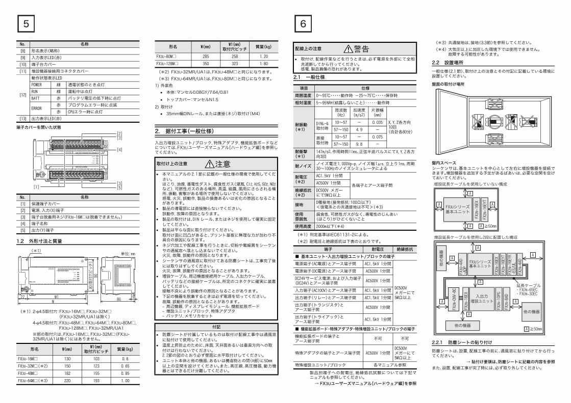
端子カバーを開いた状態
1.2 外形寸法と質量
(*1)2-4.5取付穴:FX3U-16M□,FX3U-32M□(FX3U-32MR/UA1は除く)
4-4.5取付穴:FX3U-48M□,FX3U-64M□,FX3U-80M□,FX3U-128M□,FX3U-32MR/UA1
※部の取付穴は、FX3U-16M□,FX3U-32M□(FX3U-32MR/UA1は除く)にはありません。
[8] 形名表示(略称)
[9] 入力表示LED(赤)
[10] 端子台カバー
[11] 増設機器接続用コネクタカバー
[12]
動作状態表示LED
POWER 緑 通電状態のとき点灯
RUN 緑 運転中は点灯
BATT 赤 バッテリ電圧の低下時に点灯
ERROR赤 プログラムエラー時に点滅
赤 CPUエラー時に点灯
[13] 出力表示LED(赤)
No. 名称
[1] 保護端子カバー
[2] 電源,入力(X)端子
[3] 端子台脱着用ネジ(FX3U-16M□は脱着できません。)
[4] 端子名称
[5] 出力(Y)端子
形名 W(mm)W1(mm)
取付穴ピッチ質量(kg)
FX3U-16M□ 130 103 0.6
FX3U-32M□(*2) 150 123 0.65
FX3U-48M□ 182 155 0.85
FX3U-64M□(*3) 220 193 1.00
No. 名称
[1]
[2][3]
[3][5]
[4]
(*1)単位:mm
22 W1W
86
9080(
取付
穴ピ
ッチ
)
9
(*2)FX3U-32MR/UA1は、FX3U-48M□と同じになります。
(*3)FX3U-64MR/UA1は、FX3U-80M□と同じになります。
1) 外装色
本体:マンセル0.08GY/7.64/0.81
トップカバー:マンセルN1.5
2) 取付け
35mm幅DINレール、または直接(ネジ)取付け(M4)
2. 据付工事(一般仕様)
入出力増設ユニット/ブロック,特殊アダプタ,機能拡張ボードなどについては、FX3Uユーザーズマニュアル[ハードウェア編]を参照してください。
FX3U-80M□ 285 258 1.20
FX3U-128M□ 350 323 1.80
取付け上の注意
本マニュアルの 2.1 節に記載の一般仕様の環境で使用してください。ほこり,油煙,導電性ダスト,腐食性ガス(潮風,Cl2,H2S,SO2,NO2など),可燃性ガスのある場所、高温,結露,風雨にさらされる場所、振動,衝撃がある場所で使用しないでください。感電,火災,誤動作,製品の損傷あるいは劣化の原因となることがあります。
製品の導電部には直接触らないでください。誤動作,故障の原因となります。
製品の取付けは、DIN レール、またはネジを使用して確実に固定してください。
製品は平らな面に取り付けてください。取付け面に凹凸があると、プリント基板に無理な力が加わり不具合の原因になります。
ネジ穴加工や配線工事を行うときに、切粉や電線屑をシーケンサの通風窓へ落とし込まないでください。火災,故障,誤動作の原因となります。
シーケンサの通風窓に取付けてある防塵シートは、工事完了後には取りはずしてください。火災,故障,誤動作の原因となることがあります。
増設ケーブル,周辺機器接続用ケーブル,入出力ケーブル,バッテリなどの接続ケーブルは、所定のコネクタに確実に装着してください。接触不良により誤動作の原因となることがあります。
下記の機器を脱着するときは必ず電源を切ってください。故障,誤動作の原因となることがあります。- 周辺機器,ディスプレイモジュール,機能拡張ボード- 増設ユニット/ブロック,特殊アダプタ- バッテリ,メモリカセット
付記
防塵シートが付属しているものは取付け配線工事中は通風窓に貼付けて使用してください。
温度上昇防止のために、床面,天井面あるいは垂直方向への取付けは行わないでください。2.2節の図のとおり必ず壁面に水平取付けしてください。
ユニット本体と他の機器、あるいは構造物との間(A部)に50mm以上の空間を設けてください。また、高圧線,高圧機器,動力機器とはできるだけ分離してください。
形名 W(mm)W1(mm)
取付穴ピッチ質量(kg)
2.1 一般仕様
(*1)判定基準はIEC61131-2による。
(*2)耐電圧と絶縁抵抗は下表のとおりです。
製品別端子への耐電圧,絶縁抵抗試験については下記マニュアルも参照してください。
→ FX3Uユーザーズマニュアル[ハードウェア編]を参照
配線上の注意
取付け,配線作業などを行うときは、必ず電源を外部にて全相共遮断してから行ってください。感電,製品損傷の恐れがあります。
項目 仕様
周囲温度 0~55℃・・・・・動作時 -25~75℃・・・・・保存時
相対湿度 5~95%RH(結露しないこと)‥‥‥動作時
耐振動(*1)
周波数(Hz)
加速度(m/s2)
片振幅(mm)
X,Y,Z各方向10回
(合計各80分)
DINレール取付時
10~57 - 0.035
57~150 4.9 -
直接取付時
10~57 - 0.075
57~150 9.8 -
耐衝撃(*1)
147m/s2、作用時間11ms、正弦半波パルスにてX,Y,Z各方向3回
耐ノイズノイズ電圧1,000Vp-p,ノイズ幅1μs,立上り1ns,周期30~100Hzのノイズシミュレータによる
耐電圧(*2)
AC1.5kV 1分間
各端子とアース端子間AC500V 1分間
絶縁抵抗(*2)
DC500V メガーにて5MΩ以上
接地D種接地(接地抵抗:100Ω以下)<強電系との共通接地は不可>(*3)
使用雰囲気
腐食性,可燃性ガスがなく、導電性のじんあい(ほこり)がひどくないこと
使用高度 2000m以下(*4)
端子 耐電圧 絶縁抵抗
■ 基本ユニット・入出力増設ユニット/ブロックの端子
電源端子(AC電源)とアース端子間 AC1.5kV 1分間
DC500Vメガーにて5MΩ以上
電源端子(DC電源)とアース端子間 AC500V 1分間
DC24Vサービス電源、および入力端子(DC24V)とアース端子間
AC500V 1分間
入力端子(AC100V)とアース端子間 AC1.5kV 1分間
出力端子(リレー)とアース端子間 AC1.5kV 1分間
出力端子(トランジスタ)とアース端子間
AC500V 1分間
出力端子(トライアック)とアース端子間
AC1.5kV 1分間
■ 機能拡張ボード・特殊アダプタ・特殊増設ユニット/ブロックの端子
機能拡張ボードの端子とアース端子間
不可 不可
特殊アダプタの端子とアース端子間 AC500V 1分間DC500Vメガーにて5MΩ以上
特殊増設ユニット/ブロック 各マニュアル参照
(*3)共通接地は、接地(3.3節)を参照してください。
(*4)大気圧以上に加圧した環境下では使用できません。故障する可能性があります。
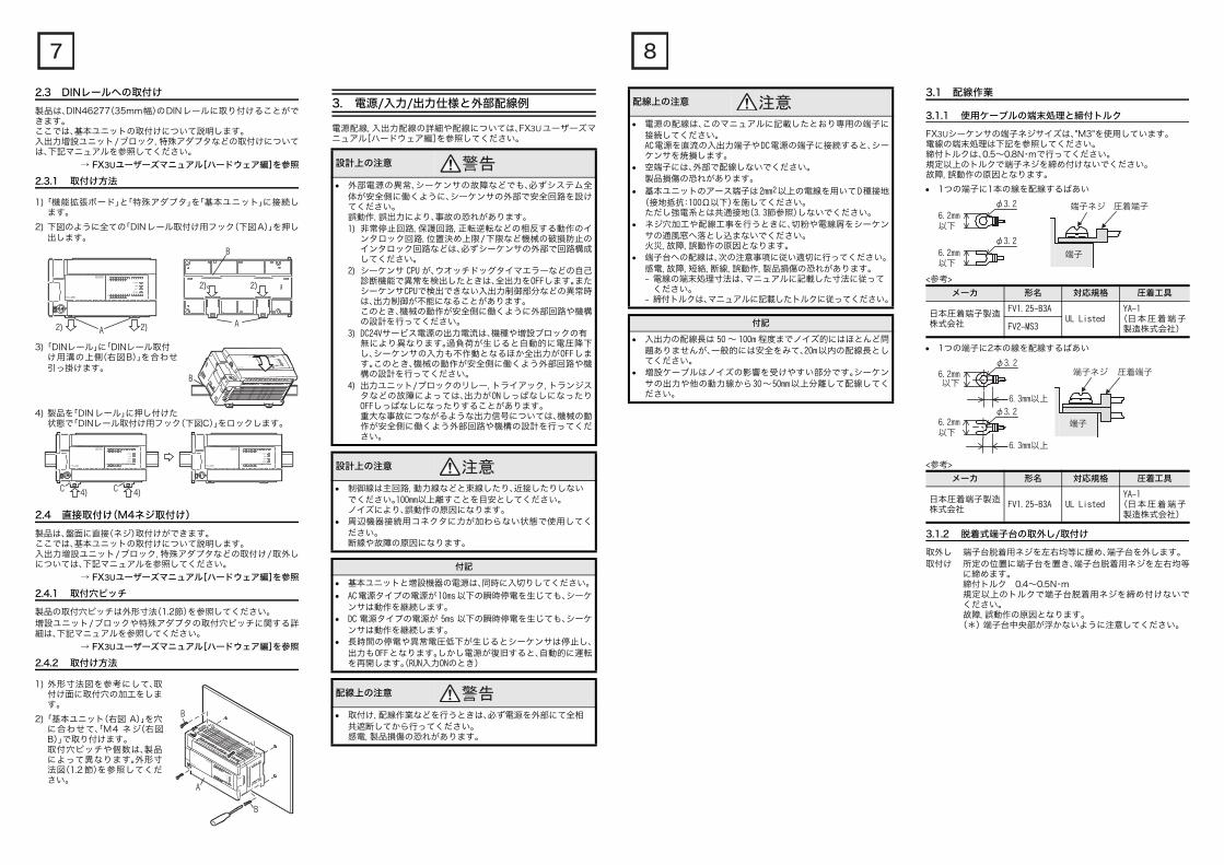
2.2 設置場所
一般仕様(2.1節)、取付け上の注意とその付記に記載している環境に設置してください。
盤面の取付け場所
盤内スペースシーケンサは、基本ユニットを中心として左右に増設機器を接続できます。増設機器を追加する予定があるばあいは、必要な空間を空けておいてください。
2.2.1 防塵シートの貼り付け
防塵シートは、設置,配線工事の前に、通風窓に貼り付けてから行ってください。
→ 貼付け要領は、防塵シートに記載の内容を参照
また、設置,配線工事が完了時には、必ず取り外してください。
FX3Uシリーズ基本ユニット
FX2N
-16E
X
FX2N
-16E
YT
増設延長ケーブルを使用していない構成
A
A
A A
≧50mmA
他の機器
他の機器
A
A
A
A
A
A
延長ケーブル・FX0N-65EC・FX0N-30EC
他の
機器
A
≧50mmA
増設延長ケーブルを使用し2段に配置した構成
FX2N
-CNV
-BC
入出力増設ユニット
FX2N
-16E
X
FX2N
-10P
G
FX2N
-8AD
FX3Uシリーズ基本ユニット
FX2N
-16E
X
FX2N
-16E
YT
FX2N
-4AD
FX2N
-16E
YR-E
S/UL
FX3U
-4AD
-ADP
2.3 DINレールへの取付け
製品は、DIN46277(35mm幅)のDINレールに取り付けることができます。ここでは、基本ユニットの取付けについて説明します。入出力増設ユニット/ブロック,特殊アダプタなどの取付けについては、下記マニュアルを参照してください。
→ FX3Uユーザーズマニュアル[ハードウェア編]を参照
2.3.1 取付け方法
1)「機能拡張ボード」と「特殊アダプタ」を「基本ユニット」に接続します。
2) 下図のように全ての「DINレール取付け用フック(下図A)」を押し出します。
3)「DINレール」に「DINレール取付け用溝の上側(右図B)」を合わせ引っ掛けます。
4) 製品を「DINレール」に押し付けた状態で「DINレール取付け用フック(下図C)」をロックします。
2.4 直接取付け(M4ネジ取付け)
製品は、盤面に直接(ネジ)取付けができます。ここでは、基本ユニットの取付けについて説明します。入出力増設ユニット/ブロック,特殊アダプタなどの取付け/取外しについては、下記マニュアルを参照してください。
→ FX3Uユーザーズマニュアル[ハードウェア編]を参照
2.4.1 取付穴ピッチ
製品の取付穴ピッチは外形寸法(1.2節)を参照してください。増設ユニット/ブロックや特殊アダプタの取付穴ピッチに関する詳細は、下記マニュアルを参照してください。
→ FX3Uユーザーズマニュアル[ハードウェア編]を参照
2.4.2 取付け方法
1) 外形寸法図を参考にして、取付け面に取付穴の加工をします。
2)「基本ユニット(右図 A)」を穴に合わせて、「M4 ネジ(右図B)」で取り付けます。取付穴ピッチや個数は、製品によって異なります。外形寸法図(1.2 節)を参照してください。
A 2)2)
2)
A
2)
B
B
C 4) C 4)
B
A
B
3. 電源/入力/出力仕様と外部配線例
電源配線,入出力配線の詳細や配線については、FX3Uユーザーズマニュアル[ハードウェア編]を参照してください。
設計上の注意
外部電源の異常、シーケンサの故障などでも、必ずシステム全体が安全側に働くように、シーケンサの外部で安全回路を設けてください。誤動作,誤出力により、事故の恐れがあります。1) 非常停止回路,保護回路,正転逆転などの相反する動作のイ
ンタロック回路,位置決め上限/下限など機械の破損防止のインタロック回路などは、必ずシーケンサの外部で回路構成してください。
2) シーケンサ CPU が、ウオッチドッグタイマエラーなどの自己診断機能で異常を検出したときは、全出力をOFFします。またシーケンサCPUで検出できない入出力制御部分などの異常時は、出力制御が不能になることがあります。このとき、機械の動作が安全側に働くように外部回路や機構の設計を行ってください。
3) DC24Vサービス電源の出力電流は、機種や増設ブロックの有無により異なります。過負荷が生じると自動的に電圧降下し、シーケンサの入力も不作動となるほか全出力がOFFします。このとき、機械の動作が安全側に働くよう外部回路や機構の設計を行ってください。
4) 出力ユニット/ブロックのリレー,トライアック,トランジスタなどの故障によっては、出力がONしっぱなしになったりOFFしっぱなしになったりすることがあります。重大な事故につながるような出力信号については、機械の動作が安全側に働くよう外部回路や機構の設計を行ってください。
設計上の注意
制御線は主回路,動力線などと束線したり、近接したりしないでください。100mm以上離すことを目安としてください。ノイズにより、誤動作の原因になります。
周辺機器接続用コネクタに力が加わらない状態で使用してください。断線や故障の原因になります。
付記
基本ユニットと増設機器の電源は、同時に入切りしてください。
AC 電源タイプの電源が10ms以下の瞬時停電を生じても、シーケンサは動作を継続します。
DC 電源タイプの電源が 5ms 以下の瞬時停電を生じても、シーケンサは動作を継続します。
長時間の停電や異常電圧低下が生じるとシーケンサは停止し、出力もOFFとなります。しかし電源が復旧すると、自動的に運転を再開します。(RUN入力ONのとき)
配線上の注意
取付け,配線作業などを行うときは、必ず電源を外部にて全相共遮断してから行ってください。感電,製品損傷の恐れがあります。
配線上の注意
電源の配線は、このマニュアルに記載したとおり専用の端子に接続してください。AC電源を直流の入出力端子やDC電源の端子に接続すると、シーケンサを焼損します。
空端子には、外部で配線しないでください。製品損傷の恐れがあります。
基本ユニットのアース端子は2mm2以上の電線を用いてD種接地(接地抵抗:100Ω以下)を施してください。ただし強電系とは共通接地(3.3節参照)しないでください。
ネジ穴加工や配線工事を行うときに、切粉や電線屑をシーケンサの通風窓へ落とし込まないでください。火災,故障,誤動作の原因となります。
端子台への配線は、次の注意事項に従い適切に行ってください。感電,故障,短絡,断線,誤動作,製品損傷の恐れがあります。- 電線の端末処理寸法は、マニュアルに記載した寸法に従って
ください。- 締付トルクは、マニュアルに記載したトルクに従ってください。
付記
入出力の配線長は 50 ~ 100m 程度までノイズ的にはほとんど問題ありませんが、一般的には安全をみて、20m以内の配線長としてください。
増設ケーブルはノイズの影響を受けやすい部分です。シーケンサの出力や他の動力線から30~50mm以上分離して配線してください。
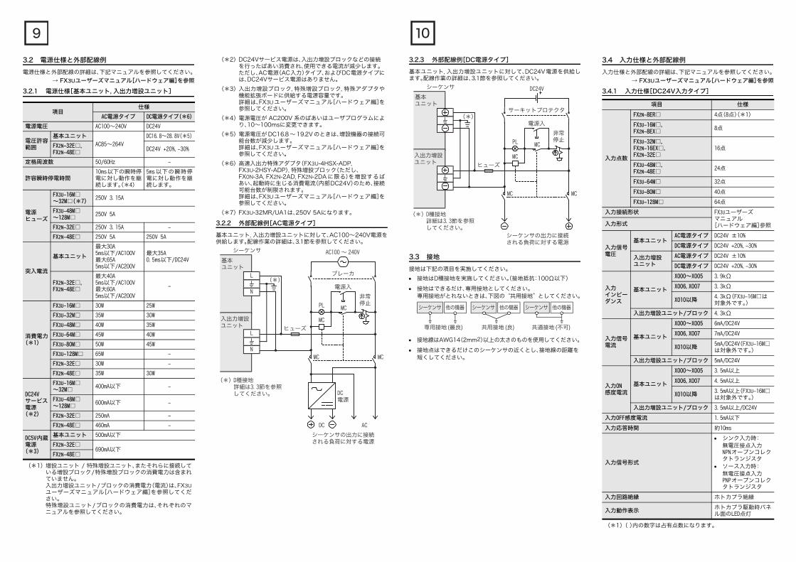
3.1 配線作業
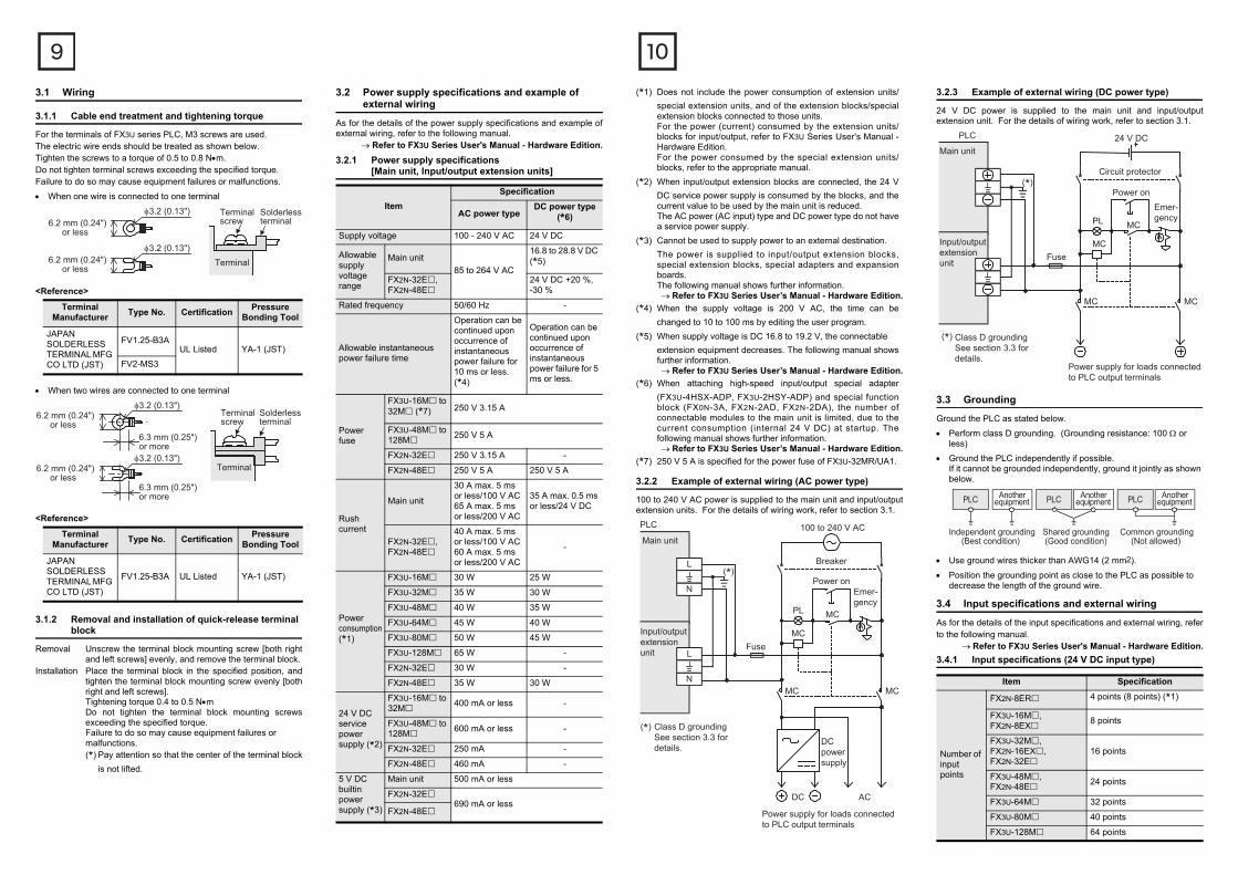
3.1.1 使用ケーブルの端末処理と締付トルク
FX3Uシーケンサの端子ネジサイズは、"M3"を使用しています。電線の端末処理は下記を参照してください。締付トルクは、0.5~0.8N・mで行ってください。規定以上のトルクで端子ネジを締め付けないでください。故障,誤動作の原因となります。
1つの端子に1本の線を配線するばあい
<参考>
1つの端子に2本の線を配線するばあい
<参考>
3.1.2 脱着式端子台の取外し/取付け
取外し 端子台脱着用ネジを左右均等に緩め、端子台を外します。取付け 所定の位置に端子台を置き、端子台脱着用ネジを左右均等
に締めます。締付トルク 0.4~0.5N・m規定以上のトルクで端子台脱着用ネジを締め付けないでください。故障,誤動作の原因となります。
(*) 端子台中央部が浮かないように注意してください。
メーカ 形名 対応規格 圧着工具
日本圧着端子製造株式会社
FV1.25-B3AUL Listed
YA-1(日本圧着端子製造株式会社)FV2-MS3
メーカ 形名 対応規格 圧着工具
日本圧着端子製造株式会社
FV1.25-B3A UL ListedYA-1
(日本圧着端子製造株式会社)
φ3.2
φ3.2
6.2mm以下
6.2mm以下
端子
端子ネジ 圧着端子
端子
端子
φ3.26.2mm以下
6.3mm以上
φ3.26.2mm以下
6.3mm以上
端子ネジ 圧着端子
3.2 電源仕様と外部配線例
電源仕様と外部配線の詳細は、下記マニュアルを参照してください。
→ FX3Uユーザーズマニュアル[ハードウェア編]を参照
3.2.1 電源仕様[基本ユニット,入出力増設ユニット]
(*1)増設ユニット / 特殊増設ユニット、またそれらに接続している増設ブロック/特殊増設ブロックの消費電力は含まれていません。入出力増設ユニット/ブロックの消費電力(電流)は、FX3Uユーザーズマニュアル[ハードウェア編]を参照してください。特殊増設ユニット/ブロックの消費電力は、それぞれのマニュアルを参照してください。
項目仕様
AC電源タイプ DC電源タイプ(*6)
電源電圧 AC100~240V DC24V
電圧許容範囲
基本ユニット
AC85~264V
DC16.8~28.8V(*5)
FX2N-32E□,FX2N-48E□
DC24V +20%,-30%
定格周波数 50/60Hz -
許容瞬時停電時間10ms以下の瞬時停電に対し動作を継続します。(*4)
5ms 以下の瞬時停電に対し動作を継続します。
電源ヒューズ
FX3U-16M□~32M□(*7)
250V 3.15A
FX3U-48M□~128M□
250V 5A
FX2N-32E□ 250V 3.15A -
FX2N-48E□ 250V 5A 250V 5A
突入電流
基本ユニット
最大30A5ms以下/AC100V最大65A5ms以下/AC200V
最大35A0.5ms以下/DC24V
FX2N-32E□,FX2N-48E□
最大40A5ms以下/AC100V最大60A5ms以下/AC200V
-
消費電力(*1)
FX3U-16M□ 30W 25W
FX3U-32M□ 35W 30W
FX3U-48M□ 40W 35W
FX3U-64M□ 45W 40W
FX3U-80M□ 50W 45W
FX3U-128M□ 65W -
FX2N-32E□ 30W -
FX2N-48E□ 35W 30W
DC24Vサービス電源
(*2)
FX3U-16M□~32M□
400mA以下 -
FX3U-48M□~128M□
600mA以下 -
FX2N-32E□ 250mA -
FX2N-48E□ 460mA -
DC5V内蔵電源
(*3)
基本ユニット 500mA以下
FX2N-32E□690mA以下
FX2N-48E□
(*2)DC24Vサービス電源は、入出力増設ブロックなどの接続を行ったばあい消費され、使用できる電流が減少します。ただし、AC電源(AC入力)タイプ、およびDC電源タイプには、DC24Vサービス電源はありません。
(*3)入出力増設ブロック,特殊増設ブロック,特殊アダプタや機能拡張ボードに供給する電源容量です。詳細は、FX3Uユーザーズマニュアル[ハードウェア編]を参照してください。
(*4)電源電圧が AC200V 系のばあいはユーザプログラムにより、10~100msに変更できます。
(*5)電源電圧が DC16.8 ~ 19.2V のときは、増設機器の接続可能台数が減少します。詳細は、FX3Uユーザーズマニュアル[ハードウェア編]を参照してください。
(*6)高速入出力特殊アダプタ(FX3U-4HSX-ADP,FX3U-2HSY-ADP),特殊増設ブロック(ただし、FX0N-3A,FX2N-2AD,FX2N-2DA に限る)を増設するばあい、起動時に生じる消費電流(内部DC24V)のため、接続可能台数が制限されます。詳細は、FX3Uユーザーズマニュアル[ハードウェア編]を参照してください。
(*7)FX3U-32MR/UA1は、250V 5Aになります。
3.2.2 外部配線例[AC電源タイプ]
基本ユニット,入出力増設ユニットに対して、AC100~240V電源を供給します。配線作業の詳細は、3.1節を参照してください。
AC100 ~ 240V
PL
電源入
非常停止
MC
MC
DC電源
シーケンサの出力に接続される負荷に対する電源
DC AC
MCMC
(*)D種接地詳細は3.3節を参照してください。
ブレーカ
ヒューズ
L
N
シーケンサ
L
N
基本ユニット
入出力増設ユニット
(*)
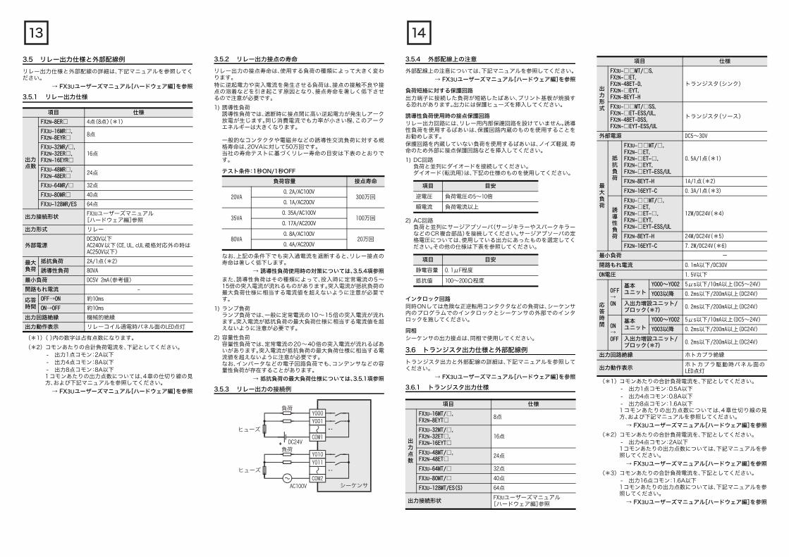
3.2.3 外部配線例[DC電源タイプ]
基本ユニット,入出力増設ユニットに対して、DC24V電源を供給します。配線作業の詳細は、3.1節を参照してください。
3.3 接地
接地は下記の項目を実施してください。
接地はD種接地を実施してください。(接地抵抗:100Ω以下)
接地はできるだけ、専用接地としてください。専用接地がとれないときは、下図の“共用接地”としてください。
接地線はAWG14(2mm2)以上の太さのものを使用してください。
接地点はできるだけこのシーケンサの近くとし、接地線の距離を短くしてください。
DC24V
PL
電源入
非常停止
MC
MC
シーケンサの出力に接続される負荷に対する電源
MCMC
(*)D種接地詳細は3.3節を参照してください。
サーキットプロテクタ
ヒューズ
シーケンサ
基本ユニット
入出力増設ユニット
(*)
シーケンサ 他の機器 シーケンサ 他の機器 シーケンサ 他の機器
共用接地(良) 共通接地(不可)専用接地(最良)
3.4 入力仕様と外部配線例
入力仕様と外部配線の詳細は、下記マニュアルを参照してください。
→ FX3Uユーザーズマニュアル[ハードウェア編]を参照
3.4.1 入力仕様[DC24V入力タイプ]
(*1)( )内の数字は占有点数になります。
項目 仕様
入力点数
FX2N-8ER□ 4点(8点)(*1)
FX3U-16M□,FX2N-8EX□
8点
FX3U-32M□,FX2N-16EX□,FX2N-32E□
16点
FX3U-48M□,FX2N-48E□
24点
FX3U-64M□ 32点
FX3U-80M□ 40点
FX3U-128M□ 64点
入力接続形状 FX3Uユーザーズマニュアル
[ハードウェア編]参照入力形式
入力信号電圧
基本ユニットAC電源タイプ DC24V ±10%
DC電源タイプ DC24V +20%,-30%
入出力増設ユニット
AC電源タイプ DC24V ±10%
DC電源タイプ DC24V +20%,-30%
入力インピーダンス
基本ユニット
X000~X005 3.9kΩ
X006,X007 3.3kΩ
X010以降4.3kΩ(FX3U-16M□は対象外です。)
入出力増設ユニット/ブロック 4.3kΩ
入力信号電流
基本ユニット
X000~X005 6mA/DC24V
X006,X007 7mA/DC24V
X010以降5mA/DC24V(FX3U-16M□は対象外です。)
入出力増設ユニット/ブロック 5mA/DC24V
入力ON感度電流
基本ユニット
X000~X005 3.5mA以上
X006,X007 4.5mA以上
X010以降3.5mA以上(FX3U-16M□は対象外です。)
入出力増設ユニット/ブロック 3.5mA以上/DC24V
入力OFF感度電流 1.5mA以下
入力応答時間 約10ms
入力信号形式
シンク入力時:無電圧接点入力NPNオープンコレクタトランジスタ
ソース入力時:無電圧接点入力PNPオープンコレクタトランジスタ
入力回路絶縁 ホトカプラ絶縁
入力動作表示ホトカプラ駆動時パネル面のLED点灯

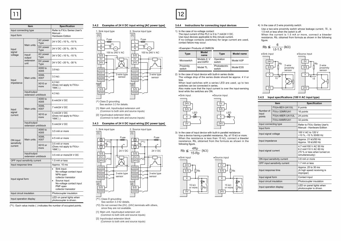
3.4.2 DC24V入力の接続例[AC電源タイプ]
3.4.3 DC24V入力の接続例[DC電源タイプ]
(*)
AC100~240V
ヒューズL
N
S/S
0V
24V
X000
X001
X002
X003
3線式センサ
(*)
AC100~240V
ヒューズ
(*)D種接地詳細は、3.3節を参照してください。
L
N
S/S
0V
24V
X000
X001
X002
X003
3線式センサ
1.シンク入力 2.ソース入力
S/S
X000
S/S
X000
[1] [1]
[2] [2]
[2]:入出力増設ブロック (シンク/ソース入力共用タイプ)
[1]:基本ユニット/入出力増設ユニット (シンク/ソース入力共用タイプ)
X000
X001
X002
X003
3線式センサ
(*1)
ヒューズ
(*1)D種接地詳細は、3.3節を参照してください。
S/S
X000
(0V)
(24V)
X001
X002
X003
3線式センサ
1.シンク入力 2.ソース入力
S/S
X000
S/S
X000
[1] [1]
[2] [2]
[2]:入出力増設ブロック (シンク/ソース入力共用タイプ)
[1]:基本ユニット/入出力増設ユニット (シンク/ソース入力共用タイプ)
S/S
(*2) (*2)
(*1)
ヒューズ
(*2)(0V),(24V)端子は使用できません。配線を行わないでください。
DC24VDC24V
(0V)
(24V)
3.4.4 入力機器接続上の注意
1) 無電圧接点のばあいこのシーケンサの入力電流は、5~7mA/DC24Vです。入力機器はこの微小電流に適したものを使用してください。大電流用の無電圧接点(スイッチなど)を用いると、接触不良が生じることがあります。
《例》オムロン株式会社製
2) 直列ダイオードを内蔵した入力機器のばあい直列ダイオードの電圧降下を約4V以下としてください。直列LED付リードスイッチのばあい、その直列使用は2個以下としてください。また、ON時には入力感度電流以上になるようにしてください。
3) 並列抵抗を内蔵した入力機器のばあい並列抵抗Rpが15kΩ以上のものを使用してください。15kΩ未満のときは次式で求めたブリーダ抵抗Rbを下図のように接続してください。
種類 形名 種類 形名
マイクロスイッチ
Z形,V形,D2RV形
操作スイッチ A3P形
近接スイッチ TL形 光電スイッチ E3S形
X
0V
LED
24V
S/S
X
24V
LED
0V
S/S
・シンク入力 ・ソース入力
Rb≦4Rp
15-Rp(kΩ)
X
24V
0V
S/S
Rp
Rb
X
0V
24V
S/S
Rp
Rb
15kΩ以上
15kΩ以上
・シンク入力 ・ソース入力
4) 2線式の近接センサ(スイッチ)のばあい2線式の近接センサのOFF時、もれ電流 が1.5mA以下のものを使用してください。1.5mA以上のときは下図のように次式で求められたブリーダ抵抗Rbを接続してください。
3.4.5 入力仕様[AC100V入力タイプ]
項目 仕様
入力点数
FX2N-8EX-UA1/UL 8点
FX3U-32MR/UA1 16点
FX2N-48ER-UA1/UL 24点
FX3U-64MR/UA1 32点
入力接続形状 FX3Uユーザーズマニュアル[ハードウェア編]参照入力形式
入力信号電圧 AC100~120V +10%,-15% 50/60Hz
入力インピーダンス 約21kΩ/50Hz 約18kΩ/60Hz
入力信号電流4.7mA/AC100V 50Hz6.2mA/AC110V 60Hz
(同時ON率は70%以下としてください。)
入力ON感度電流 3.8mA以上
入力OFF感度電流 1.7mA以下
入力応答時間 約25~30ms (高速取込不可)
入力信号形式 接点入力
入力回路絶縁 ホトカプラ絶縁
入力動作表示 ホトカプラ駆動時パネル面のLED点灯
I
2線式近接センサ
I
X
24V
0V
S/SRb
X
0V
24V
S/SRb
2線式近接センサ
Rb≦6
I -1.5(kΩ)
・シンク入力 ・ソース入力
I
3.4.6 AC100V入力の接続例
(*1)
ヒューズ
ヒューズ
ヒューズ
(*1)D種接地詳細は、3.3節を参照してください。
(*2)サージを発生する負荷から入力信号をとらないでください。
L
N
COM
AC100~120V
AC100~240V
X000X001
X002
COMX000
X001MC(*2)
[1]
[1]: 基本ユニット/入出力増設ユニット(AC100V入力タイプ)[2]: 入力増設ブロック(AC100V入力タイプ)
[2]
3.5 リレー出力仕様と外部配線例
リレー出力仕様と外部配線の詳細は、下記マニュアルを参照してください。
→ FX3Uユーザーズマニュアル[ハードウェア編]を参照
3.5.1 リレー出力仕様
(*1)( )内の数字は占有点数になります。
(*2)コモンあたりの合計負荷電流を、下記としてください。- 出力1点コモン:2A以下- 出力4点コモン:8A以下- 出力8点コモン:8A以下1コモンあたりの出力点数については、4章の仕切り線の見方、および下記マニュアルを参照してください。
→ FX3Uユーザーズマニュアル[ハードウェア編]を参照
項目 仕様
出力点数
FX2N-8ER□ 4点(8点)(*1)
FX3U-16MR□,FX2N-8EYR□
8点
FX3U-32MR/□,FX2N-32ER□,FX2N-16EYR□
16点
FX3U-48MR□,FX2N-48ER□
24点
FX3U-64MR/□ 32点
FX3U-80MR□ 40点
FX3U-128MR/ES 64点
出力接続形状FX3Uユーザーズマニュアル
[ハードウェア編]参照
出力形式 リレー
外部電源DC30V以下AC240V以下(CE,UL,cUL規格対応外の時はAC250V以下)
最大負荷
抵抗負荷 2A/1点(*2)
誘導性負荷 80VA
最小負荷 DC5V 2mA(参考値)
開路もれ電流 -
応答時間
OFF→ON 約10ms
ON→OFF 約10ms
出力回路絶縁 機械的絶縁
出力動作表示 リレーコイル通電時パネル面のLED点灯
3.5.2 リレー出力接点の寿命
リレー出力の接点寿命は、使用する負荷の種類によって大きく変わります。特に逆起電力や突入電流を発生させる負荷は、接点の接触不良や接点の溶着などを引き起こす原因となり、接点寿命を著しく低下させるので注意が必要です。
1) 誘導性負荷誘導性負荷では、遮断時に接点間に高い逆起電力が発生しアーク放電が生じます。同じ消費電流でも力率が小さい程、このアークエネルギーは大きくなります。
一般的なコンタクタや電磁弁などの誘導性交流負荷に対する規格寿命は、20VAに対して50万回です。当社の寿命テストに基づくリレー寿命の目安は下表のとおりです。
テスト条件:1秒ON/1秒OFF
なお、上記の条件下でも突入過電流を遮断すると、リレー接点の寿命は著しく低下します。
→ 誘導性負荷使用時の対策については、3.5.4項参照
また、誘導性負荷はその種類によって、投入時に定常電流の5~15倍の突入電流が流れるものがあります。突入電流が抵抗負荷の最大負荷仕様に相当する電流値を超えないように注意が必要です。
1) ランプ負荷ランプ負荷では、一般に定常電流の10~15倍の突入電流が流れます。突入電流が抵抗負荷の最大負荷仕様に相当する電流値を超えないように注意が必要です。
2) 容量性負荷容量性負荷では、定常電流の20~40倍の突入電流が流れるばあいがあります。突入電流が抵抗負荷の最大負荷仕様に相当する電流値を超えないように注意が必要です。なお、インバータなどの電子回路負荷でも、コンデンサなどの容量性負荷が存在することがあります。
→ 抵抗負荷の最大負荷仕様については、3.5.1項参照
3.5.3 リレー出力の接続例
負荷容量 接点寿命
20VA0.2A/AC100V
300万回0.1A/AC200V
35VA0.35A/AC100V
100万回0.17A/AC200V
80VA0.8A/AC100V
20万回0.4A/AC200V
シーケンサ
DC24V
ヒューズ
Y000
AC100V
COM1
Y001
負荷
ヒューズ
Y010
COM2
Y011
負荷
3.5.4 外部配線上の注意
外部配線上の注意については、下記マニュアルを参照してください。
→ FX3Uユーザーズマニュアル[ハードウェア編]を参照
負荷短絡に対する保護回路出力端子に接続した負荷が短絡したばあい、プリント基板が焼損する恐れがあります。出力には保護ヒューズを挿入してください。
誘導性負荷使用時の接点保護回路リレー出力回路には、リレー用内部保護回路を設けていません。誘導性負荷を使用するばあいは、保護回路内蔵のものを使用することをお勧めします。保護回路を内蔵していない負荷を使用するばあいは、ノイズ軽減,寿命のため外部に接点保護回路などを挿入してください。
1) DC回路負荷と並列にダイオードを接続してください。ダイオード(転流用)は、下記の仕様のものを使用してください。
2) AC回路負荷と並列にサージアブソーバ(サージキラーやスパークキラーなどのCR複合部品)を接続してください。サージアブソーバの定格電圧については、使用している出力にあったものを選定してください。その他の仕様は下表を参照してください。
インタロック回路同時ONしては危険な正逆転用コンタクタなどの負荷は、シーケンサ内のプログラムでのインタロックとシーケンサの外部でのインタロックを施してください。
同相シーケンサの出力接点は、同相で使用してください。
3.6 トランジスタ出力仕様と外部配線例
トランジスタ出力と外部配線の詳細は、下記マニュアルを参照してください。
→ FX3Uユーザーズマニュアル[ハードウェア編]を参照
3.6.1 トランジスタ出力仕様
項目 目安
逆電圧 負荷電圧の5~10倍
順電流 負荷電流以上
項目 目安
静電容量 0.1μF程度
抵抗値 100~200Ω程度
項目 仕様
出力点数
FX3U-16MT/□,FX2N-8EYT□
8点
FX3U-32MT/□,FX2N-32ET□,FX2N-16EYT□
16点
FX3U-48MT/□,FX2N-48ET□
24点
FX3U-64MT/□ 32点
FX3U-80MT/□ 40点
FX3U-128MT/ES(S) 64点
出力接続形状FX3Uユーザーズマニュアル
[ハードウェア編]参照
(*1)コモンあたりの合計負荷電流を、下記としてください。- 出力1点コモン:0.5A以下- 出力4点コモン:0.8A以下- 出力8点コモン:1.6A以下1コモンあたりの出力点数については、4章仕切り線の見方、および下記マニュアルを参照してください。
→ FX3Uユーザーズマニュアル[ハードウェア編]を参照
(*2)コモンあたりの合計負荷電流を、下記としてください。- 出力4点コモン:2A以下1コモンあたりの出力点数については、下記マニュアルを参照してください。
→ FX3Uユーザーズマニュアル[ハードウェア編]を参照
(*3)コモンあたりの合計負荷電流を、下記としてください。- 出力16点コモン:1.6A以下1コモンあたりの出力点数については、下記マニュアルを参照してください。
→ FX3Uユーザーズマニュアル[ハードウェア編]を参照
出力形式
FX3U-□□MT/□S,FX2N-□ET,FX2N-48ET-D,FX2N-□EYT,FX2N-8EYT-H
トランジスタ(シンク)
FX3U-□□MT/□SS,FX2N-□ET-ESS/UL,FX2N-48ET-DSS,FX2N-□EYT-ESS/UL
トランジスタ(ソース)
外部電源 DC5~30V
最大負荷
抵抗負荷
FX3U-□□MT/□,FX2N-□ET,FX2N-□ET-□,FX2N-□EYT,FX2N-□EYT-ESS/UL
0.5A/1点(*1)
FX2N-8EYT-H 1A/1点(*2)
FX2N-16EYT-C 0.3A/1点(*3)
誘導性負荷
FX3U-□□MT/□,FX2N-□ET,FX2N-□ET-□,FX2N-□EYT,FX2N-□EYT-ESS/UL
12W/DC24V(*4)
FX2N-8EYT-H 24W/DC24V(*5)
FX2N-16EYT-C 7.2W/DC24V(*6)
最小負荷 -
開路もれ電流 0.1mA以下/DC30V
ON電圧 1.5V以下
応答時間
OFF→ON
基本ユニット
Y000~Y002 5μs以下/10mA以上(DC5~24V)
Y003以降 0.2ms以下/200mA以上(DC24V)
入出力増設ユニット/ブロック(*7)
0.2ms以下/200mA以上(DC24V)
ON→OFF
基本ユニット
Y000~Y002 5μs以下/10mA以上(DC5~24V)
Y003以降 0.2ms以下/200mA以上(DC24V)
入出力増設ユニット/ブロック(*7)
0.2ms以下/200mA以上(DC24V)
出力回路絶縁 ホトカプラ絶縁
出力動作表示ホトカプラ駆動時パネル面のLED点灯
項目 仕様
(*4)コモンあたりの合計負荷を、下記としてください。- 出力1点コモン:12W以下/DC24V- 出力4点コモン:19.2W以下/DC24V- 出力8点コモン:38.4W以下/DC24V1コモンあたりの出力点数については、4章仕切り線の見方、および下記マニュアルを参照してください。
→ FX3Uユーザーズマニュアル[ハードウェア編]を参照
(*5)コモンあたりの合計負荷を、下記としてください。- 出力4点コモン:48W以下/DC24V1コモンあたりの出力点数については、下記マニュアルを参照してください。
→ FX3Uユーザーズマニュアル[ハードウェア編]を参照
(*6)コモンあたりの合計負荷を、下記としてください。- 出力16点コモン:38.4W以下1コモンあたりの出力点数については、下記マニュアルを参照してください。
→ FX3Uユーザーズマニュアル[ハードウェア編]を参照
(*7)FX2N-8EYT-Hの応答時間は下記になります。- OFF→ON:0.2ms以下/1A- ON→OFF:0.4ms以下/1A
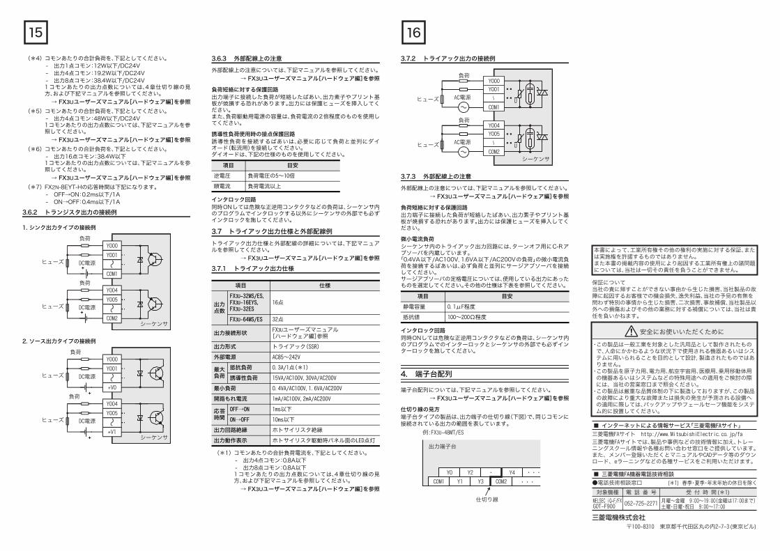
3.6.2 トランジスタ出力の接続例
1. シンク出力タイプの接続例
2. ソース出力タイプの接続例
シーケンサ
負荷
DC電源ヒューズ
Y000
Y001
COM1
負荷
DC電源ヒューズ
Y004
Y005
COM2
シーケンサ
負荷
DC電源ヒューズ
Y000
Y001
+V0
負荷
DC電源ヒューズ
Y004
Y005
+V1
3.6.3 外部配線上の注意
外部配線上の注意については、下記マニュアルを参照してください。
→ FX3Uユーザーズマニュアル[ハードウェア編]を参照
負荷短絡に対する保護回路出力端子に接続した負荷が短絡したばあい、出力素子やプリント基板が焼損する恐れがあります。出力には保護ヒューズを挿入してください。また、負荷駆動用電源の容量は、負荷電流の2倍程度のものを使用してください。
誘導性負荷使用時の接点保護回路誘導性負荷を接続するばあいは、必要に応じて負荷と並列にダイオード(転流用)を接続してください。ダイオードは、下記の仕様のものを使用してください。
インタロック回路同時ONしては危険な正逆用コンタクタなどの負荷は、シーケンサ内のプログラムでインタロックする以外にシーケンサの外部でも必ずインタロックを施してください。
3.7 トライアック出力仕様と外部配線例
トライアック出力仕様と外部配線の詳細については、下記マニュアルを参照してください。
→ FX3Uユーザーズマニュアル[ハードウェア編]を参照
3.7.1 トライアック出力仕様
(*1)コモンあたりの合計負荷電流を、下記としてください。- 出力4点コモン:0.8A以下- 出力8点コモン:0.8A以下1コモンあたりの出力点数については、4章仕切り線の見方、および下記マニュアルを参照してください。
→ FX3Uユーザーズマニュアル[ハードウェア編]を参照
項目 目安
逆電圧 負荷電圧の5~10倍
順電流 負荷電流以上
項目 仕様
出力点数
FX3U-32MS/ES,FX3U-16EYS,FX3U-32ES
16点
FX3U-64MS/ES 32点
出力接続形状FX3Uユーザーズマニュアル
[ハードウェア編]参照
出力形式 トライアック(SSR)
外部電源 AC85~242V
最大負荷
抵抗負荷 0.3A/1点(*1)
誘導性負荷 15VA/AC100V,30VA/AC200V
最小負荷 0.4VA/AC100V,1.6VA/AC200V
開路もれ電流 1mA/AC100V,2mA/AC200V
応答時間
OFF→ON 1ms以下
ON→OFF 10ms以下
出力回路絶縁 ホトサイリスタ絶縁
出力動作表示 ホトサイリスタ駆動時パネル面のLED点灯
3.7.2 トライアック出力の接続例
3.7.3 外部配線上の注意
外部配線上の注意については、下記マニュアルを参照してください。
→ FX3Uユーザーズマニュアル[ハードウェア編]を参照
負荷短絡に対する保護回路出力端子に接続した負荷が短絡したばあい、出力素子やプリント基板が焼損する恐れがあります。出力には保護ヒューズを挿入してください。
微小電流負荷シーケンサ内のトライアック出力回路には、ターンオフ用にC-Rアブソーバを内蔵しています。
「0.4VA以下/AC100V,1.6VA以下/AC200Vの負荷」の微小電流負荷を接続するばあいは、必ず負荷と並列にサージアブソーバを接続してください。サージアブソーバの定格電圧については、使用している出力にあったものを選定してください。その他の仕様は下表を参照してください。
インタロック回路同時ONしては危険な正逆用コンタクタなどの負荷は、シーケンサ内のプログラムでのインターロックとシーケンサの外部でも必ずインターロックを施してください。
4. 端子台配列
端子台配列については、下記マニュアルを参照してください。
→ FX3Uユーザーズマニュアル[ハードウェア編]を参照
仕切り線の見方端子台タイプの製品は、出力端子の仕切り線(下図)で、同じコモンに接続されている出力の範囲を表しています。
項目 目安
静電容量 0.1μF程度
抵抗値 100~200Ω程度
シーケンサ
AC電源U
AC電源Uヒューズ
ヒューズ
負荷
負荷
Y000
COM1
Y001
Y004
COM2
Y005
例:FX3U-48MT/ES
出力端子台
仕切り線
COM1
Y0 Y4
Y1 Y3 COM2
Y2
・・・
・・・・
保証について当社の責に帰すことができない事由から生じた損害、当社製品の故障に起因するお客様での機会損失、逸失利益、当社の予見の有無を問わず特別の事情から生じた損害、二次損害、事故補償、当社製品以外への損傷およびその他の業務に対する補償については、当社は責任を負いかねます。
・この製品は一般工業を対象とした汎用品として製作されたもの で、人命にかかわるような状況下で使用される機器あるいはシス テムに用いられることを目的として設計,製造されたものではあ りません。・この製品を原子力用、電力用、航空宇宙用、医療用、乗用移動体用 の機器あるいはシステムなどの特殊用途への適用をご検討の際 には、当社の営業窓口まで照会ください。・この製品は厳重な品質体制の下に製造しておりますが、この製品 の故障により重大な故障または損失の発生が予測される設備へ の適用に際しては、バックアップやフェールセーフ機能をシステ ム的に設置してください。
〒100-8310 東京都千代田区丸の内2-7-3(東京ビル)
安全にお使いいただくために
●電話技術相談窓口
対象機種 電 話 番 号 受 付 時 間(*1)
MELSEC iQ-F/FXGOT-F900
月曜~金曜 9:00~19:00(金曜は17:00まで)土曜・日曜・祝日 9:00~17:00
052-725-2271
(*1) 春季・夏季・年末年始の休日を除く
■ インターネットによる情報サービス「三菱電機FAサイト」
三菱電機FAサイト http://www.MitsubishiElectric.co.jp/fa
三菱電機FAサイトでは、製品や事例などの技術情報に加え、トレーニングスクール情報や各種お問い合わせ窓口をご提供しています。また、メンバー登録いただくとマニュアルやCADデータ等のダウンロード、eラーニングなどの各種サービスをご利用いただけます。
■ 三菱電機FA機器電話技術相談
本書によって、工業所有権その他の権利の実施に対する保証、または実施権を許諾するものではありません。また本書の掲載内容の使用により起因する工業所有権上の諸問題については、当社は一切その責任を負うことができません。

FX3U SERIES PROGRAMMABLE CONTROLLERS
HARDWARE MANUAL
This manual describes the part names, dimensions, mounting,cabling and specifications for the product. This manual is extractedfrom FX3U Series User's Manual - Hardware Edition. Refer to FX3USeries User's Manual - Hardware Edition for more details. Beforeuse, read this manual and manuals of relevant products fully toacquire proficiency in the handling and operating the product. Makesure to learn all the product information, safety information, andprecautions.And, store this manual in a safe place so that you can take it out andread it whenever necessary. Always forward it to the end user.RegistrationThe company name and the product name to be described in thismanual are the registered trademarks or trademarks of eachcompany.
Effective April 2015Specifications are subject to change without notice.
© 2013 Mitsubishi Electric Corporation
Safety Precaution (Read these precautions before use.)
This manual classifies the safety precautions into two categories:
and .
Depending on the circumstances, procedures indicated by
may also cause severe injury.It is important to follow all precautions for personal safety.
Manual Number JY997D50301
Revision B
Date April 2015
Indicates that incorrect handling may cause hazardous conditions, resulting in death or severe injury.
Indicates that incorrect handling may cause hazardous conditions, resulting in medium or slight personal injury or physical damage.
STARTUP AND MAINTENANCE PRECAUTIONS
Do not touch any terminal while the PLC's power is on.Doing so may cause electric shock or malfunctions.
Before cleaning or retightening terminals, cut off all phases ofthe power supply externally.Failure to do so may cause electric shock.
Before modifying or disrupting the program in operation orrunning the PLC, carefully read through this manual and theassociated manuals and ensure the safety of the operation.An operation error may damage the machinery or causeaccidents.
Do not change the program in the PLC from two or moreperipheral equipment devices at the same time. (i.e. from aprogramming tool and a GOT) Doing so may cause destruction or malfunction of the PLCprogram.
Use the battery for memory backup correctly in FX3U SeriesUser's Manual - Hardware Edition.- Use the battery only for the specified purpose.- Connect the battery correctly.- Do not charge, disassemble, heat, put in fire, short-circuit,
connect reversely, weld, swallow or burn the battery, or apply excessive forces (vibration, impact, drop, etc.) to the battery.
- Do not store or use the battery at high temperatures or expose to direct sunlight.
- Do not expose to water, bring near fire or touch liquid leakage or other contents directly.
- Incorrect handling of the battery may cause heat excessive generation, bursting, ignition, liquid leakage or deformation, and lead to injury, fire or failures and malfunctions of facilities and other equipment.
STARTUP AND MAINTENANCE PRECAUTIONS
Turn off the power to the PLC before attaching or detaching thememory cassette. If the memory cassette is attached ordetached while the PLC's power is on, the data in the memorymay be destroyed, or the memory cassette may be damaged.
Do not disassemble or modify the PLC.Doing so may cause fire, equipment failures, or malfunctions.For repair, contact your local Mitsubishi Electric distributor.
Turn off the power to the PLC before connecting ordisconnecting any extension cable.Failure to do so may cause equipment failures or malfunctions.
Turn off the power to the PLC before attaching or detaching thefollowing devices.Failure to do so may cause equipment failures or malfunctions.- Display module, peripheral devices, expansion boards, and
special adapters- Connector conversion adapter, extension blocks, and FX
Series terminal blocks- Battery and memory cassette
DISPOSAL PRECAUTIONS
Please contact a certified electronic waste disposal companyfor the environmentally safe recycling and disposal of yourdevice.When disposing of batteries, separate them from other wasteaccording to local regulations.(For details of the Battery Directive in EU countries, refer toFX3U Series User's Manual - Hardware Edition.)
Associated manuals
Associated manualsFX3U Series PLC (main unit) comes with this document (hardwaremanual).For a detailed explanation of the FX3U Series hardware andinformation on instructions for PLC programming and specialextension unit/block, refer to the relevant documents.
TRANSPORTATION AND STORAGE PRECAUTIONS
Before transporting the PLC, turn on the power to the PLC tocheck that the BATT LED is off.If the PLC is transported with the BATT LED on or the batteryexhausted, the battery-backed data may be unstable duringtransportation.
The PLC is a precision instrument. During transportation, avoidimpacts larger than those specified in Section 2.1. Failure to doso may cause failures in the PLC.After transportation, verify the operations of the PLC.
When transporting lithium batteries, follow required transportation regulations.(For details of the regulated products, refer to FX3U SeriesUser's Manual - Hardware Edition.)
How to obtain manuals
For the necessary product manuals or documents, consult with your local Mitsubishi Electric representative.
Manual name Manual No. Description
FX3U Series User's Manual - Hardware Edition
JY997D16501MODEL CODE:
09R516
Explains FX3U Series PLC specification details for I/O, wiring, installation, and maintenance.
FX3S/FX3G/FX3GC/FX3U/FX3UC Series Programming Manual - Basic & Applied Instruction Edition
JY997D16601MODEL CODE:
09R517
Describes PLC programming for basic/applied instructions STL/SFC programming and devices.
MELSEC-Q/L/FStructuredProgramming Manual(Fundamentals)
SH-080782MODEL CODE:
13JW06
Programming methods, specifications, functions, etc. required to create structured programs.
FXCPU StructuredProgramming Manual[Device & Common]
JY997D26001MODEL CODE:
09R925
Devices, parameters, etc. provided in structured projects of GX Works2.
FXCPU StructuredProgramming Manual[Basic & Applied Instruction]
JY997D34701MODEL CODE:
09R926
Sequence instructions provided in structured projects of GX Works2.
FXCPU StructuredProgramming Manual[Application Functions]
JY997D34801MODEL CODE:
09R927
Application functions provided in structured projects of GX Works2.
FX Series User’s Manual - Data Communication Edition
JY997D16901MODEL CODE:
09R715
Explains N:N link, parallel link, computer link, no protocol communication by RS instructions/FX2N-232IF.
Marine standard
Please consult with Mitsubishi Electric for the information on marinestandard practices and the corresponding types of equipment.
Certification of UL, cUL standards
FX3U series main units, FX3U series special adapters and FX2Nseries input/output extension units/blocks supporting UL, cULstandards are as follows:
UL, cUL file number: E95239Models: MELSEC FX3U series manufactured
FX3U-MR/ES(-A) FX3U-MT/ES(-A)FX3U-MT/ESSWhere indicates: 16, 32, 48, 64, 80, 128FX3U-MR/DS FX3U-MT/DSFX3U-MT/DSSWhere indicates: 16, 32, 48, 64, 80FX3U-MR/UA1 FX3U-MS/ESWhere indicates: 32, 64FX3U-232ADP(-MB) FX3U-485ADP(-MB)FX3U-4AD-ADP FX3U-4DA-ADPFX3U-3A-ADP FX3U-4AD-PT-ADPFX3U-4AD-PTW-ADP FX3U-4AD-PNK-ADPFX3U-4AD-TC-ADPFX3U-4HSX-ADP FX3U-2HSY-ADPFX3U-CF-ADP FX3U-ENET-ADP
Models: MELSEC FX2N series manufacturedFX2N-ER-ES/UL FX2N-ET-ESS/ULWhere indicates: 32, 48FX2N-48ER-DS FX2N-48ET-DSSFX2N-48ER-UA1/ULFX2N-8ER-ES/UL FX2N-8EX-ES/ULFX2N-8EYR-ES/UL FX2N-8EYR-S-ES/ULFX2N-8EYT-ESS/UL FX2N-8EX-UA1/ULFX2N-16EX-ES/UL FX2N-16EYR-ES/ULFX2N-16EYT-ESS/UL FX2N-16EYS
Compliance with EC directive (CE Marking)
This document does not guarantee that a mechanical systemincluding this product will comply with the following standards.Compliance to EMC directive and LVD directive of the entiremechanical system should be checked by the user/manufacturer.For more details please contact the local Mitsubishi Electric salessite.
Requirement for Compliance with EMC directive
The following products have shown compliance through directtesting (of the identified standards below) and design analysis(through the creation of a technical construction file) to the European
FX3S/FX3G/FX3GC/FX3U/FX3UC Series User's Manual - Analog Control Edition
JY997D16701MODEL CODE:
09R619
Describes specifications for analog control and programming methods for FX3S/FX3G/FX3GC/FX3U/FX3UC Series PLC.
FX3S/FX3G/FX3GC/FX3U/FX3UC Series User's Manual - Positioning Control Edition
JY997D16801MODEL CODE:
09R620
Explains the specifications for positioning control of FX3S/FX3G/FX3GC/FX3U/FX3UC Series and programming procedures
Manual name Manual No. Description
SideB
SideA
Side
B JAPANESE ENGLISH
JY997D50301B
Directive for Electromagnetic Compatibility (2004/108/EC) whenused as directed by the appropriate documentation.Attention This product is designed for use in industrial applications.Note Authorized Representative in the European Community:
Mitsubishi Electric Europe B.V.Gothaer Str. 8, 40880 Ratingen, Germany
Type: Programmable Controller (Open Type Equipment)Models: MELSEC FX3U series manufacturedfrom May 1st, 2005 FX3U-MR/ES(-A)
Where indicates: 16, 32, 48, 64, 80FX3U-4HSX-ADP FX3U-2HSY-ADPFX3U-FLROM-16 FX3U-FLROM-64LFX3U-7DM
from June 1st, 2005 FX3U-232ADP FX3U-485ADPFX3U-4AD-ADP FX3U-4DA-ADPFX3U-4AD-PT-ADP FX3U-4AD-TC-ADPFX3U-232-BD FX3U-422-BDFX3U-485-BD FX3U-USB-BDFX3U-FLROM-64 FX3U-CNV-BD
from November 1st, 2005 FX3U-MT/ES(-A)FX3U-MT/ESSWhere indicates: 16, 32, 48, 64, 80
from February 1st, 2006 FX3U-128MR/ES(-A) FX3U-128MT/ES(-A)FX3U-128MT/ESSFX3U-MR/DS FX3U-MT/DSFX3U-MT/DSSWhere indicates: 16, 32, 48, 64, 80
from April 1st, 2007 FX3U-232ADP-MB FX3U-485ADP-MBfrom December 1st, 2007 FX3U-4AD-PTW-ADP
FX3U-4AD-PNK-ADPfrom June 1st, 2009 FX3U-3A-ADP FX3U-CF-ADPfrom August 1st, 2010 FX3U-8AV-BDfrom September 1st, 2010 FX3U-MR/UA1 FX3U-MS/ES
Where indicates: 32, 64from May 1st, 2011 FX3U-FLROM-1Mfrom February 1st, 2012 FX3U-ENET-ADP
Models: MELSEC FX2N series manufacturedfrom July 1st, 1997 FX2N-ER-ES/UL FX2N-ET-ESS/UL
Where indicates: 32, 48FX2N-16EX-ES/UL FX2N-16EYR-ES/ULFX2N-16EYT-ESS/UL
from April 1st, 1998 FX2N-48ER-DS FX2N-48ET-DSSfrom August 1st, 1998 FX2N-48ER-UA1/ULfrom August 1st, 2005 FX2N-8ER-ES/UL FX2N-8EX-ES/UL
FX2N-8EYR-ES/UL FX2N-8EYT-ESS/ULfrom September 1st, 2010 FX2N-8EYR-S-ES/ULFor the products above, PLCs manufacturedbefore March 31st, 2002 are compliant with EN50081-2 (EN61000-6-4) and EN50082-2from April 1st, 2002 to April 30th, 2006 are compliant with EN50081-2 (EN61000-6-4) and EN61131-2: 1994 +A11: 1996 +A12: 2000after May 1st, 2006 are compliant with EN61131-2: 2007
Standard RemarkEN61131-2: 2007
Programmable controllers- Equipment
requirements and tests
Compliance with all relevant aspects of the standard.EMI Radiated Emission Conducted EmissionEMS Radiated electromagnetic field Fast transient burst Electrostatic discharge High-energy surge Voltage drops and interruptions Conducted RF Power frequency magnetic field
Requirement for Compliance with LVD directive
The following products have shown compliance through directtesting (of the identified standards below) and design analysis(through the creation of a technical construction file) to the EuropeanDirective for Low Voltage (2006/95/EC) when used as directed bythe appropriate documentation.
Type: Programmable Controller (Open Type Equipment)Models: MELSEC FX3U series manufacturedfrom May 1st, 2005 FX3U-MR/ES(-A)
Where indicates: 16, 32, 48, 64, 80from November 1st, 2005 FX3U-MT/ES(-A)
FX3U-MT/ESSWhere indicates: 16, 32, 48, 64, 80
from February 1st, 2006 FX3U-128MR/ES(-A)FX3U-128MT/ES(-A)FX3U-128MT/ESSFX3U-MR/DSWhere indicates: 16, 32, 48, 64, 80
from September 1st, 2010 FX3U-MR/UA1FX3U-MS/ESWhere indicates: 32, 64
Standard RemarkEN61000-6-4: 2007
- Generic emission standard
Industrial environmentEN50081-2: 1993
Electromagnetic compatibility
Compliance with all relevant aspects of the standard. Emission-Enclosure port Emission-Low voltage AC mains
port Emission-Telecommunications/
network portEN50082-2: 1995
Electromagnetic compatibility- Generic immunity
standardIndustrial environment
Compliance with all relevant aspects of the standard. RF immunity Fast transients ESD Conducted Power magnetic fields
EN61131-2: 1994 /A11: 1996 /A12: 2000
Programmable controllers- Equipment
requirements and tests
Compliance with all relevant aspects of the standard. Radiated electromagnetic field Fast transient burst Electrostatic discharge Damped oscillatory wave
EN61131-2: 2007Programmable controllers- Equipment
requirements and tests
Compliance with all relevant aspects of the standard.EMI Radiated Emission Conducted EmissionEMS Radiated electromagnetic field Fast transient burst Electrostatic discharge High-energy surge Voltage drops and interruptions Conducted RF Power frequency magnetic field
Standard Remark
EN61131-2: 2007Programmable controllers- Equipment
requirements and tests
The equipment has been assessed as a component for fitting in a suitable enclosure which meets the requirements of EN61131-2: 2007
Models: MELSEC FX2N series manufacturedfrom July 1st, 1997 FX2N-ER-ES/UL FX2N-ET-ESS/UL
Where indicates: 32, 48FX2N-16EYR-ES/UL
from April 1st, 1998 FX2N-48ER-DSfrom August 1st, 1998 FX2N-48ER-UA1/ULfrom August 1st, 2005 FX2N-8ER-ES/UL FX2N-8EYR-ES/ULfrom September 1st, 2010 FX2N-8EYR-S-ES/UL
For the products above, PLCs manufacturedbefore March 31st, 2002 are compliant with IEC1010-1from April 1st, 2002 to April 30th, 2006 are compliant with EN61131-2: 1994 +A11: 1996 +A12: 2000after May 1st, 2006 are compliant with EN61131-2: 2007
Caution for compliance with EC Directive
Installation in EnclosureProgrammable logic controllers are open-type devices that must beinstalled and used within conductive control boxes. Please use theFX3U Series programmable logic controllers while installed inconductive shielded control boxes. Please secure the control box lidto the control box (for conduction). Installation within a control boxgreatly affects the safety of the system and aids in shielding noisefrom the programmable logic controller.
Caution for Analog Products in useThe analog special adapters have been found to be compliant to theEuropean standards in the aforesaid manual and directive. However,for the very best performance from what are in fact delicatemeasuring and controlled output device Mitsubishi Electric would liketo make the following points;As analog devices are sensitive by nature, their use should beconsidered carefully. For users of proprietary cables (integral withsensors or actuators), these users should follow thosemanufacturers installation requirements.Mitsubishi Electric recommend that shielded cables should be used.If NO other EMC protection is provided, then users may experiencetemporary induced errors not exceeding +10 %/-10 % in very heavyindustrial areas.However, Mitsubishi Electric suggest that if adequate EMCprecautions are followed with general good EMC practice for theusers complete control system, users should expect normal errorsas specified in this manual.
- Sensitive analog cable should not be laid in the same trunking or cable conduit as high voltage cabling. Where possible users should run analog cables separately.
- Good cable shielding should be used. When terminating the shield at Earth - ensure that no earth loops are accidentally created.
- When reading analog values, EMC induced errors can be smoothed out by averaging the readings. This can be achieved either through functions on the analog special adapter/block or through a users program in the FX3U Series PLC main unit.
Standard Remark
IEC1010-1: 1990 /A1: 1992
Safety requirements for electrical equipment for measurement, control, and laboratory use- General requirements
The equipment has been assessed as a component for fitting in a suitable enclosure which meets the requirements of IEC 1010-1:1990 +A1: 1992
EN61131-2: 1994 : 2007 /A12: 2000 /A11: 1996
Programmable controllers- Equipment
requirements and tests
The equipment has been assessed as a component for fitting in a suitable enclosure which meets the requirements of EN61131-2:1994 +A11: 1996 +A12: 2000, : 2007
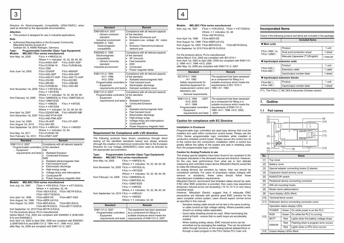
Incorporated Items
Check if the following product and items are included in the package:
(*1) The FX3U-M/ES-A becomes Chinese version.
1. Outline
1.1 Part names
Included Items Main units
FX3U-16M toFX3U-128M
Product 1 unit
Dust proof protection sheet 1 sheet
Manuals [Japanese (*1)/English] 1 manual
Input/output extension units
FX2N-32E,FX2N-48E
Product 1 unitExtension cable 1 cable
Input/output number label 1 sheet
Input/output extension blocks
FX2N-8E, FX2N-16E
Product 1 unit
Input/output number label 1 sheet
No. Name[1] Top cover
[2] Battery cover
[3] Special adapter connecting hooks (2 places)
[4] Expansion board dummy cover
[5] RUN/STOP switch
[6] Peripheral device connecting connector
[7] DIN rail mounting hooks
[8] Model name (abbreviation)
[9] Input display LEDs (Red)
[10] Terminal block covers
[11] Extension device connecting connector cover
[12]
Operation status display LEDs
POWER Green On while power is on the PLC.
RUN Green On while the PLC is running.
BATT Red Lights when the battery voltage drops.
ERRORRed Flashing when a program error occurs.
Red Lights when a CPU error occurs.
[13] Output display LEDs (Red)
[1][2][3]
[9][10]
[11]
[12]
[13][8]
[4]
[5]
[6][7]
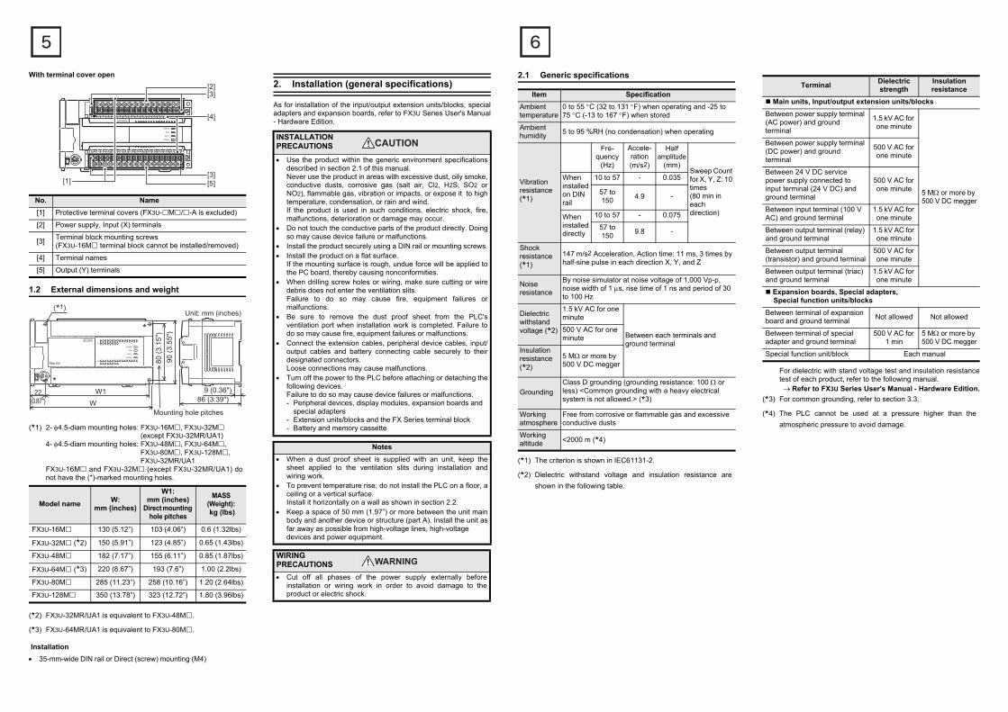
With terminal cover open
1.2 External dimensions and weight
(*1) 2- 4.5-diam mounting holes: FX3U-16M, FX3U-32M (except FX3U-32MR/UA1)
4- 4.5-diam mounting holes: FX3U-48M, FX3U-64M, FX3U-80M, FX3U-128M,FX3U-32MR/UA1
FX3U-16M and FX3U-32M (except FX3U-32MR/UA1) donot have the (*)-marked mounting holes.
(*2) FX3U-32MR/UA1 is equivalent to FX3U-48M.
(*3) FX3U-64MR/UA1 is equivalent to FX3U-80M.
Installation 35-mm-wide DIN rail or Direct (screw) mounting (M4)
No. Name[1] Protective terminal covers (FX3U-M/-A is excluded)
[2] Power supply, Input (X) terminals
[3] Terminal block mounting screws (FX3U-16M terminal block cannot be installed/removed)
[4] Terminal names
[5] Output (Y) terminals
Model name W:mm (inches)
W1:mm (inches)
Direct mounting hole pitches
MASS (Weight): kg (lbs)
FX3U-16M 130 (5.12”) 103 (4.06”) 0.6 (1.32lbs)
FX3U-32M (*2) 150 (5.91”) 123 (4.85”) 0.65 (1.43lbs)
FX3U-48M 182 (7.17”) 155 (6.11”) 0.85 (1.87lbs)
FX3U-64M (*3) 220 (8.67”) 193 (7.6”) 1.00 (2.2lbs)
FX3U-80M 285 (11.23”) 258 (10.16”) 1.20 (2.64lbs)
FX3U-128M 350 (13.78”) 323 (12.72”) 1.80 (3.96lbs)
[2]
[5]
[3]
[3][1]
[4]
WW122
(0.87")
Unit: mm (inches)
90 (3
.55"
)80
(3.1
5")
86 (3.39")
(*1)
9 (0.36")
Mounting hole pitches
*
*
2. Installation (general specifications)
As for installation of the input/output extension units/blocks, specialadapters and expansion boards, refer to FX3U Series User's Manual- Hardware Edition.
INSTALLATION PRECAUTIONS
Use the product within the generic environment specificationsdescribed in section 2.1 of this manual.Never use the product in areas with excessive dust, oily smoke,conductive dusts, corrosive gas (salt air, Cl2, H2S, SO2 orNO2), flammable gas, vibration or impacts, or expose it to hightemperature, condensation, or rain and wind.If the product is used in such conditions, electric shock, fire,malfunctions, deterioration or damage may occur.
Do not touch the conductive parts of the product directly. Doingso may cause device failure or malfunctions.
Install the product securely using a DIN rail or mounting screws. Install the product on a flat surface.
If the mounting surface is rough, undue force will be applied tothe PC board, thereby causing nonconformities.
When drilling screw holes or wiring, make sure cutting or wiredebris does not enter the ventilation slits.Failure to do so may cause fire, equipment failures ormalfunctions.
Be sure to remove the dust proof sheet from the PLC'sventilation port when installation work is completed. Failure todo so may cause fire, equipment failures or malfunctions.
Connect the extension cables, peripheral device cables, input/output cables and battery connecting cable securely to theirdesignated connectors.Loose connections may cause malfunctions.
Turn off the power to the PLC before attaching or detaching thefollowing devices.Failure to do so may cause device failures or malfunctions.- Peripheral devices, display modules, expansion boards and
special adapters- Extension units/blocks and the FX Series terminal block- Battery and memory cassette
Notes When a dust proof sheet is supplied with an unit, keep the
sheet applied to the ventilation slits during installation andwiring work.
To prevent temperature rise, do not install the PLC on a floor, aceiling or a vertical surface.Install it horizontally on a wall as shown in section 2.2.
Keep a space of 50 mm (1.97”) or more between the unit mainbody and another device or structure (part A). Install the unit asfar away as possible from high-voltage lines, high-voltage devices and power equipment.
WIRING PRECAUTIONS Cut off all phases of the power supply externally before
installation or wiring work in order to avoid damage to theproduct or electric shock.
2.1 Generic specifications
(*1) The criterion is shown in IEC61131-2.
(*2) Dielectric withstand voltage and insulation resistance areshown in the following table.
Item SpecificationAmbient temperature
0 to 55 C (32 to 131 F) when operating and -25 to 75 C (-13 to 167 F) when stored
Ambient humidity 5 to 95 %RH (no condensation) when operating
Vibration resistance(*1)
Fre-quency
(Hz)
Accele-ration(m/s2)
Half amplitude
(mm)Sweep Count for X, Y, Z: 10 times (80 min in each direction)
When installed on DIN rail
10 to 57 - 0.035
57 to 150 4.9 -
When installed directly
10 to 57 - 0.075
57 to 150 9.8 -
Shock resistance(*1)
147 m/s2 Acceleration, Action time: 11 ms, 3 times by half-sine pulse in each direction X, Y, and Z
Noise resistance
By noise simulator at noise voltage of 1,000 Vp-p, noise width of 1 s, rise time of 1 ns and period of 30 to 100 Hz
Dielectricwithstandvoltage (*2)
1.5 kV AC for one minute
Between each terminals and ground terminal
500 V AC for one minute
Insulation resistance(*2)
5 M or more by 500 V DC megger
GroundingClass D grounding (grounding resistance: 100 or less) <Common grounding with a heavy electrical system is not allowed.> (*3)
Working atmosphere
Free from corrosive or flammable gas and excessive conductive dusts
Working altitude <2000 m (*4)
For dielectric with stand voltage test and insulation resistancetest of each product, refer to the following manual.Refer to FX3U Series User's Manual - Hardware Edition.
(*3) For common grounding, refer to section 3.3.
(*4) The PLC cannot be used at a pressure higher than theatmospheric pressure to avoid damage.
Terminal Dielectric strength
Insulation resistance
Main units, Input/output extension units/blocksBetween power supply terminal (AC power) and ground terminal
1.5 kV AC for one minute
5 M or more by 500 V DC megger
Between power supply terminal (DC power) and ground terminal
500 V AC for one minute
Between 24 V DC service power supply connected to input terminal (24 V DC) and ground terminal
500 V AC for one minute
Between input terminal (100 V AC) and ground terminal
1.5 kV AC for one minute
Between output terminal (relay) and ground terminal
1.5 kV AC for one minute
Between output terminal (transistor) and ground terminal
500 V AC for one minute
Between output terminal (triac) and ground terminal
1.5 kV AC for one minute
Expansion boards, Special adapters, Special function units/blocksBetween terminal of expansion board and ground terminal Not allowed Not allowed
Between terminal of special adapter and ground terminal
500 V AC for 1 min
5 M or more by 500 V DC megger
Special function unit/block Each manual
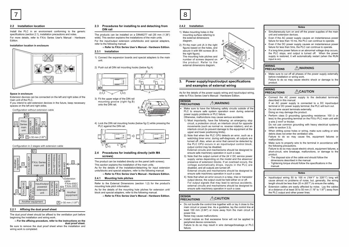
2.2 Installation location
Install the PLC in an environment conforming to the genericspecifications (section 2.1), installation precautions and notes.For more details, refer to FX3U Series User's Manual - HardwareEdition.
Installation location in enclosure
Space in enclosureExtension devices can be connected on the left and right sides of themain unit of the PLC.If you intend to add extension devices in the future, keep necessaryspaces on the left and right sides.
2.2.1 Affixing the dust proof sheet
The dust proof sheet should be affixed to the ventilation port beforebeginning the installation and wiring work.
For the affixing procedure, refer to the instructions on thedust proof sheet.
Be sure to remove the dust proof sheet when the installation andwiring work is completed.
≥ 50 mm (1.97")
A
A
A A
AFX3USeriesmainunit
FX2N
-16E
X-E
S/U
LFX
2N-1
6EY
T-E
SS
/UL
Configuration without extension cable
Another equipment
Anotherequipment
Extensioncable·FX0N-65EC·FX0N-30EC
Ano
ther
equi
pmen
t
A
A
A
A
A
A
A
A ≥ 50 mm (1.97")
Configuration in 2 stages with extension cable
FX2
N-CN
V-BC Input/output
poweredextension
unitFX2N
-16E
X-E
S/U
L
FX2N
-10P
G
FX2N
-8A
D
FX3U Seriesmain unit
FX2N
-16E
X-ES
/UL
FX2N
-16E
YT-E
SS/U
L
FX2N
-4A
D
FX2N
-16E
YR-E
S/UL
FX3U
-4A
D-A
DP
2.3 Procedures for installing to and detaching from DIN rail
The products can be installed on a DIN46277 rail [35 mm (1.38”)wide]. This section explains the installations of the main units.For the input/output extension units/blocks and special adapters,refer to the following manual.
Refer to FX3U Series User’s Manual - Hardware Edition.2.3.1 Installation
1) Connect the expansion boards and special adapters to the mainunit.
2) Push out all DIN rail mounting hooks (below fig.A)
3) Fit the upper edge of the DIN railmounting groove (right fig.B)onto the DIN rail.
4) Lock the DIN rail mounting hooks (below fig.C) while pressing thePLC against the DIN rail.
2.4 Procedures for installing directly (with M4 screws)
The product can be installed directly on the panel (with screws).This section explains the installation of the main units.As for the details of the installation/detaching for input extensionunits/blocks and special adapters, refer to the following manual.
Refer to FX3U Series User's Manual - Hardware Edition.2.4.1 Mounting hole pitches
Refer to the External Dimensions (section 1.2) for the product'smounting hole pitch information.As for the details of the mounting hole pitches for extension unit/block and special adapters, refer to the following manual.
Refer to FX3U Series User's Manual - Hardware Edition.
A 2)2)
2)
A
2)
B
B
C 4) C 4)
2.4.2 Installation
1) Make mounting holes in the mounting surface referring to the external dimensions diagram.
2) Fit the main unit (A in the rightfigure) based on the holes, andsecure it with M4 screws (B inthe right figure).The mounting hole pitches andnumber of screws depend onthe p roduc t . Re fe r t o theexternal dimensions diagram.
3. Power supply/input/output specifications and examples of external wiring
As for the details of the power supply wiring and input/output wiring,refer to FX3U Series User's Manual - Hardware Edition.
DESIGN PRECAUTIONS Make sure to have the following safety circuits outside of the
PLC to ensure safe system operation even during externalpower supply problems or PLC failure.Otherwise, malfunctions may cause serious accidents.1) Most importantly, have the following: an emergency stop
circuit, a protection circuit, an interlock circuit for oppositemovements (such as normal vs. reverse rotation), and aninterlock circuit (to prevent damage to the equipment at theupper and lower positioning limits).
2) Note that when the PLC CPU detects an error, such as awatchdog timer error, during self-diagnosis, all outputs areturned off. Also, when an error that cannot be detected bythe PLC CPU occurs in an input/output control block,output control may be disabled.External circuits and mechanisms should be designed toensure safe machinery operation in such a case.
3) Note that the output current of the 24 V DC service powersupply varies depending on the model and the absence/presence of extension blocks. If an overload occurs, thevoltage automatically drops, inputs in the PLC aredisabled, and all outputs are turned off.External circuits and mechanisms should be designed toensure safe machinery operation in such a case.
4) Note that when an error occurs in a relay, triac or transistoroutput device, the output could be held either on or off.For output signals that may lead to serious accidents,external circuits and mechanisms should be designed toensure safe machinery operation in such a case.
DESIGN PRECAUTIONS
Do not bundle the control line together with or lay it close to themain circuit or power line. As a guideline, lay the control line atleast 100 mm (3.94") or more away from the main circuit orpower line.Noise may cause malfunctions.
Install module so that excessive force will not be applied toperipheral device connectors.Failure to do so may result in wire damage/breakage or PLCfailure.
B
A
B
Notes
Simultaneously turn on and off the power supplies of the mainunit and extension devices.
Even if the AC power supply causes an instantaneous powerfailure for less than 10 ms, the PLC can continue to operate.
Even if the DC power supply causes an instantaneous powerfailure for less than 5ms, the PLC can continue to operate.
If a long-time power failure or an abnormal voltage drop occurs,the PLC stops, and output is turned off. When the powersupply is restored, it will automatically restart (when the RUNinput is on).
WIRING PRECAUTIONS
Make sure to cut off all phases of the power supply externallybefore installation or wiring work.Failure to do so may cause electric shock or damage to theproduct.
WIRING PRECAUTIONS
Connect the AC power supply to the dedicated terminalsdescribed in this manual.If an AC power supply is connected to a DC input/outputterminal or DC power supply terminal, the PLC will burn out.
Do not wire vacant terminals externally.Doing so may damage the product.
Perform class D grounding (grounding resistance: 100 orless) to the grounding terminal on the FX3U PLC main unit witha wire 2 mm2 or thicker.Do not use common grounding with heavy electrical systems(refer to section 3.3).
When drilling screw holes or wiring, make sure cutting or wiredebris does not enter the ventilation slits.Failure to do so may cause fire, equipment failures ormalfunctions.
Make sure to properly wire to the terminal in accordance withthe following precautions.Failure to do so may cause electric shock, equipment failures, ashort-circuit, wire breakage, malfunctions, or damage to theproduct.- The disposal size of the cable end should follow the
dimensions described in the manual.- Tightening torque should follow the specifications in the
manual.
Notes
Input/output wiring 50 to 100 m (164’1” to 328’1”) long willcause almost no problems of noise, but, generally, the wiringlength should be less than 20 m (65’7”) to ensure the safety.
Extension cables are easily affected by noise. Lay the cablesat a distance of at least 30 to 50 mm (1.19” to 1.97”) away fromthe PLC output and other power lines.
3.1 Wiring
3.1.1 Cable end treatment and tightening torque
For the terminals of FX3U series PLC, M3 screws are used.The electric wire ends should be treated as shown below.Tighten the screws to a torque of 0.5 to 0.8 Nm.Do not tighten terminal screws exceeding the specified torque.Failure to do so may cause equipment failures or malfunctions.
When one wire is connected to one terminal
<Reference>
When two wires are connected to one terminal
<Reference>
3.1.2 Removal and installation of quick-release terminal block
Removal Unscrew the terminal block mounting screw [both rightand left screws] evenly, and remove the terminal block.
Installation Place the terminal block in the specified position, andtighten the terminal block mounting screw evenly [bothright and left screws].Tightening torque 0.4 to 0.5 NmDo not tighten the terminal block mounting screwsexceeding the specified torque.Failure to do so may cause equipment failures or malfunctions.(*) Pay attention so that the center of the terminal block
is not lifted.
Terminal Manufacturer Type No. Certification Pressure
Bonding Tool
JAPAN SOLDERLESS TERMINAL MFG CO LTD (JST)
FV1.25-B3AUL Listed YA-1 (JST)
FV2-MS3
Terminal Manufacturer Type No. Certification Pressure
Bonding Tool
JAPAN SOLDERLESS TERMINAL MFG CO LTD (JST)
FV1.25-B3A UL Listed YA-1 (JST)
φ3.2 (0.13")6.2 mm (0.24")
or less
Terminalscrew
Solderlessterminal
6.2 mm (0.24")or less
φ3.2 (0.13")Terminal
6.3 mm (0.25")or more
6.3 mm (0.25")or more
6.2 mm (0.24")or less
6.2 mm (0.24")or less
φ3.2 (0.13")
φ3.2 (0.13")
Terminal
Terminalscrew
Solderlessterminal
3.2 Power supply specifications and example of external wiring
As for the details of the power supply specifications and example ofexternal wiring, refer to the following manual.
Refer to FX3U Series User's Manual - Hardware Edition.3.2.1 Power supply specifications
[Main unit, Input/output extension units]
ItemSpecification
AC power typeDC power type
(*6)
Supply voltage 100 - 240 V AC 24 V DC
Allowable supply voltage range
Main unit85 to 264 V AC
16.8 to 28.8 V DC (*5)
FX2N-32E, FX2N-48E
24 V DC +20 %, -30 %
Rated frequency 50/60 Hz -
Allowable instantaneous power failure time
Operation can be continued upon occurrence of instantaneous power failure for 10 ms or less. (*4)
Operation can be continued upon occurrence of instantaneous power failure for 5 ms or less.
Power fuse
FX3U-16M to 32M (*7) 250 V 3.15 A
FX3U-48M to 128M 250 V 5 A
FX2N-32E 250 V 3.15 A -
FX2N-48E 250 V 5 A 250 V 5 A
Rush current
Main unit
30 A max. 5 ms or less/100 V AC65 A max. 5 ms or less/200 V AC
35 A max. 0.5 ms or less/24 V DC
FX2N-32E, FX2N-48E
40 A max. 5 ms or less/100 V AC60 A max. 5 ms or less/200 V AC
-
Power consumption (*1)
FX3U-16M 30 W 25 W
FX3U-32M 35 W 30 W
FX3U-48M 40 W 35 W
FX3U-64M 45 W 40 W
FX3U-80M 50 W 45 W
FX3U-128M 65 W -
FX2N-32E 30 W -
FX2N-48E 35 W 30 W
24 V DC service power supply (*2)
FX3U-16M to 32M 400 mA or less -
FX3U-48M to 128M 600 mA or less -
FX2N-32E 250 mA -
FX2N-48E 460 mA -
5 V DC builtin power supply (*3)
Main unit 500 mA or less
FX2N-32E690 mA or less
FX2N-48E
(*1) Does not include the power consumption of extension units/special extension units, and of the extension blocks/specialextension blocks connected to those units.For the power (current) consumed by the extension units/blocks for input/output, refer to FX3U Series User's Manual -Hardware Edition.For the power consumed by the special extension units/blocks, refer to the appropriate manual.
(*2) When input/output extension blocks are connected, the 24 VDC service power supply is consumed by the blocks, and thecurrent value to be used by the main unit is reduced.The AC power (AC input) type and DC power type do not havea service power supply.
(*3) Cannot be used to supply power to an external destination.The power is supplied to input/output extension blocks,special extension blocks, special adapters and expansionboards.The following manual shows further information.Refer to FX3U Series User’s Manual - Hardware Edition.
(*4) When the supply voltage is 200 V AC, the time can bechanged to 10 to 100 ms by editing the user program.
(*5) When supply voltage is DC 16.8 to 19.2 V, the connectable extension equipment decreases. The following manual showsfurther information.Refer to FX3U Series User’s Manual - Hardware Edition.
(*6) When attaching high-speed input/output special adapter(FX3U-4HSX-ADP, FX3U-2HSY-ADP) and special functionblock (FX0N-3A, FX2N-2AD, FX2N-2DA), the number ofconnectable modules to the main unit is limited, due to thecurrent consumption (internal 24 V DC) at startup. Thefollowing manual shows further information.Refer to FX3U Series User’s Manual - Hardware Edition.
(*7) 250 V 5 A is specified for the power fuse of FX3U-32MR/UA1.
3.2.2 Example of external wiring (AC power type)
100 to 240 V AC power is supplied to the main unit and input/outputextension units. For the details of wiring work, refer to section 3.1.
Power on
100 to 240 V AC
PL
MC
MC
DC AC
MCMC
Breaker(*)
L
N
PLC
L
N
Main unit
Input/outputextensionunit
Emer-gency
DCpowersupply
Power supply for loads connectedto PLC output terminals
Fuse
(*) Class D groundingSee section 3.3 fordetails.
3.2.3 Example of external wiring (DC power type)
24 V DC power is supplied to the main unit and input/outputextension unit. For the details of wiring work, refer to section 3.1.
3.3 Grounding
Ground the PLC as stated below.
Perform class D grounding. (Grounding resistance: 100 or less)
Ground the PLC independently if possible.If it cannot be grounded independently, ground it jointly as shown below.
Use ground wires thicker than AWG14 (2 mm2).
Position the grounding point as close to the PLC as possible to decrease the length of the ground wire.
3.4 Input specifications and external wiring
As for the details of the input specifications and external wiring, referto the following manual.
Refer to FX3U Series User's Manual - Hardware Edition.3.4.1 Input specifications (24 V DC input type)
Item Specification
Number of input points
FX2N-8ER 4 points (8 points) (*1)
FX3U-16M,FX2N-8EX 8 points
FX3U-32M,FX2N-16EX,FX2N-32E
16 points
FX3U-48M,FX2N-48E 24 points
FX3U-64M 32 points
FX3U-80M 40 points
FX3U-128M 64 points
24 V DC
PL
Power onEmer-gency
MC
MC
Power supply for loads connectedto PLC output terminals
MCMC
(*) Class D groundingSee section 3.3 fordetails.
Circuit protector
Fuse
(*)
PLC
Main unit
Input/outputextensionunit
PLC Anotherequipment PLC Another
equipment PLC Anotherequipment
Shared grounding(Good condition)
Common grounding(Not allowed)
Independent grounding(Best condition)
(*1) Each value inside ( ) indicates the number of occupied points.
Input connecting type Refer to FX3U Series User's Manual - Hardware EditionInput form
Input signal voltage
Main units
AC power Type 24 V DC 10 %, -10 %
DC power Type 24 V DC 20 %, -30 %
Input/output extension unit
AC power Type 24 V DC 10 %, -10 %
DC power Type 24 V DC 20 %, -30 %
Input impedance
Main units
X000 to X005 3.9 k
X006, X007 3.3 k
X010 or more
4.3 k(Does not apply to FX3U-16M.)
Input/output extension unit/block 4.3 k
Input signal current
Main units
X000 to X005 6 mA/24 V DC
X006, X007 7 mA/24 V DC
X010 or more
5 mA/24 V DC(Does not apply to FX3U-16M.)
Input/output extension unit/block 5 mA/24 V DC
ON input sensitivity current
Main units
X000 to X005 3.5 mA or more
X006, X007 4.5 mA or more
X010 or more
3.5 mA or more(Does not apply to FX3U-16M.)
Input/output extension unit/block 3.5 mA or more/24 V DC
OFF input sensitivity current 1.5 mA or less
Input response time Approx. 10 ms
Input signal form
Sink input: No-voltage contact inputNPN open collector transistor
Source input: No-voltage contact inputPNP open collector transistor
Input circuit insulation Photocoupler insulation
Input operation display LED on panel lights when photocoupler is driven.
Item Specification
3.4.2 Examples of 24 V DC input wiring [AC power type]3.4.3 Examples of 24 V DC input wiring [DC power type]
L
N
S/S0V
24V
X000X001X002X003
L
N
S/S0V
24V
X000X001X002X003
1. Sink input type 2. Source input type
S/SX000
S/SX000
(*) (*)
100 to 240 V AC
Fuse
3-wire type sensor
100 to 240 V AC
Fuse
3-wire typesensor
(*) Class D groundingSee section 3.3 for details.
[1] [1]
[2] [2]
[1]: Main unit, Input/output extension unit (Common to both sink and source inputs)[2]: Input/output extension block (Common to both sink and source inputs)
X000X001X002X003
3-wire typesensor
Fuse
(*1)
(*1) (*1)
Class D groundingSee section 3.3 for details.
S/S
X000X001X002X003
3-wire typesensor
1. Sink input type 2. Source input type
S/SX000
S/SX000
[1] [1]
[2] [2]
[2]: Input/output extension block (Common to both sink and source inputs)
[1]: Main unit, Input/output extension unit (Common to both sink and source inputs)
S/S
Fuse
(*2)
(*2) (*2)
24 V DC24 V DC
Do not connect the (0V), (24V) terminals with others,since they are not available.
(0V)(24V)
(0V)(24V)
3.4.4 Instructions for connecting input devices
1) In the case of no-voltage contact:The input current of this PLC is 5 to 7 mA/24 V DC.Use input devices applicable to this minute current.If no-voltage contacts (switches) for large current are used,contact failure may occur.
<Example> Products of OMRON
2) In the case of input device with built-in series diode:The voltage drop of the series diode should be approx. 4 V orless.When lead switches with a series LED are used, up to twoswitches can be connected in series.Also make sure that the input current is over the input-sensinglevel while the switches are ON.
3) In the case of input device with built-in parallel resistance:Use a device having a parallel resistance, Rp, of 15 kor more.When the resistance is less than 15 k, connect a bleederresistance, Rb, obtained from the formula as shown in thefollowing figure.
Type Model name Type Model name
Microswitch Models Z, V and D2RV
Operation switch Model A3P
Proximity switch Model TL Photoelectric
switch Model E3S
X
0V
LED
24V
S/S
Sink input
X
24V
LED
0V
S/S
Source input
X
24V
0V
S/S
Source input
Rp
Rb
X
0V
24V
S/S
Rp
Rb
Sink input
15 kΩor more
15 kΩor more
Rb4Rp
15-Rp(kΩ)
4) In the case of 2-wire proximity switch:Use a two-wire proximity switch whose leakage current, , is1.5 mA or less when the switch is off.When the current is 1.5 mA or more, connect a bleederresistance, Rb, obtained from formula as shown in the followingfigure.
3.4.5 Input specifications (100 V AC input type)
Item Specification
Number of input points
FX2N-8EX-UA1/UL 8 points
FX3U-32MR/UA1 16 points
FX2N-48ER-UA1/UL 24 points
FX3U-64MR/UA1 32 points
Input connecting type Refer to FX3U Series User's Manual - Hardware EditionInput form
Input signal voltage 100 V AC to 120 V +10 %, -15 % 50/60 Hz
Input impedance Approx. 21 k/50 HzApprox. 18 k/60 Hz
Input signal current
4.7 mA/100 V AC 50 Hz6.2 mA/110 V AC 60 Hz(70 % or less when turned on simultaneously)
ON input sensitivity current 3.8 mA or more
OFF input sensitivity current 1.7 mA or less
Input response timeApprox. 25 to 30 ms(A high speed receiving is improper)
Input signal form Contact input
Input circuit insulation Photocoupler insulation
Input operation display LED on panel lights when photocoupler is driven.
Ι
X
24V
0V
S/S
Source input
Rb
X
0V
24V
S/SRb
Sink input
2-wireproximitysensor
2-wireproximitysensor
Ι Ι
Rb6
Ι -1.5(kΩ)
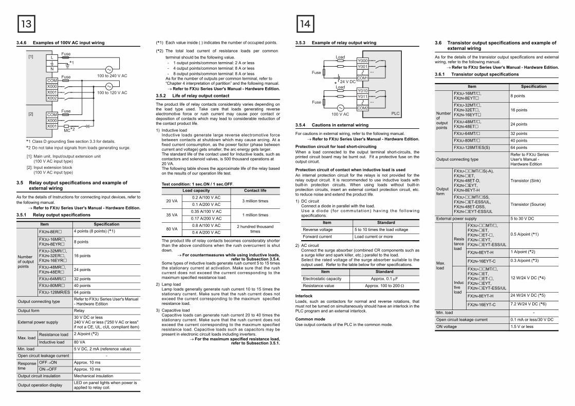
3.4.6 Examples of 100V AC input wiring
3.5 Relay output specifications and example of external wiring
As for the details of Instructions for connecting input devices, refer tothe following manual.
Refer to FX3U Series User's Manual - Hardware Edition.3.5.1 Relay output specifications
Item Specification
Number of output points
FX2N-8ER 4 points (8 points) (*1)
FX3U-16MR, FX2N-8EYR 8 points
FX3U-32MR/, FX2N-32ER, FX2N-16EYR
16 points
FX3U-48MR, FX2N-48ER 24 points
FX3U-64MR/ 32 pointsFX3U-80MR 40 pointsFX3U-128MR/ES 64 points
Output connecting type Refer to FX3U Series User's Manual - Hardware Edition
Output form Relay
External power supply30 V DC or less240 V AC or less ("250 V AC or less" if not a CE, UL, cUL compliant item)
Max. loadResistance load 2 A/point (*2)
Inductive load 80 VAMin. load 5 V DC, 2 mA (reference value)Open circuit leakage current -
Response time
OFFON Approx. 10 msONOFF Approx. 10 ms
Output circuit insulation Mechanical insulation
Output operation display LED on panel lights when power is applied to relay coil.
*1
*1 Class D grounding See section 3.3 for details.
*2 Do not take input signals from loads generating surge.
L
N
COMX000X001X002
100 to 240 V AC
100 to 120 V AC
COMX000X001
MC*2
Fuse
Fuse
Fuse
[1]
[2]
[1]: Main unit, Input/output extension unit (100 V AC input type)[2]: Input extension block (100 V AC input type)
(*1) Each value inside ( ) indicates the number of occupied points.
(*2) The total load current of resistance loads per commonterminal should be the following value.- 1 output points/common terminal: 2 A or less- 4 output points/common terminal: 8 A or less- 8 output points/common terminal: 8 A or less
As for the number of outputs per common terminal, refer to “Chapter 4 interpretation of partition” and the following manual.Refer to FX3U Series User's Manual - Hardware Edition.
3.5.2 Life of relay output contact
The product life of relay contacts considerably varies depending onthe load type used. Take care that loads generating reverseelectromotive force or rush current may cause poor contact ordeposition of contacts which may lead to considerable reduction ofthe contact product life.
1) Inductive loadInductive loads generate large reverse electromotive forcebetween contacts at shutdown which may cause arcing. At afixed current consumption, as the power factor (phase betweencurrent and voltage) gets smaller, the arc energy gets larger.The standard life of the contact used for Inductive loads, such ascontactors and solenoid valves, is 500 thousand operations at 20 VA.The following table shows the approximate life of the relay basedon the results of our operation life test.
Test condition: 1 sec.ON / 1 sec.OFF.
The product life of relay contacts becomes considerably shorterthan the above conditions when the rush overcurrent is shutdown.
For countermeasures while using inductive loads, refer to Subsection 3.5.4.
Some types of inductive loads generate rush current 5 to 15 timesthe stationary current at activation. Make sure that the rushcurrent does not exceed the current corresponding to themaximum specified resistance load.
2) Lamp loadLamp loads generally generate rush current 10 to 15 times thestationary current. Make sure that the rush current does notexceed the current corresponding to the maximum specifiedresistance load.
3) Capacitive loadCapacitive loads can generate rush current 20 to 40 times thestationary current. Make sure that the rush current does notexceed the current corresponding to the maximum specifiedresistance load. Capacitive loads such as capacitors may bepresent in electronic circuit loads including inverters.
For the maximum specified resistance load,refer to Subsection 3.5.1.
Load capacity Contact life
20 VA0.2 A/100 V AC
3 million times0.1 A/200 V AC
35 VA0.35 A/100 V AC
1 million times0.17 A/200 V AC
80 VA0.8 A/100 V AC 2 hundred thousand
times0.4 A/200 V AC
3.5.3 Example of relay output wiring
3.5.4 Cautions in external wiring
For cautions in external wiring, refer to the following manual.Refer to FX3U Series User's Manual - Hardware Edition.
Protection circuit for load short-circuitingWhen a load connected to the output terminal short-circuits, theprinted circuit board may be burnt out. Fit a protective fuse on theoutput circuit.
Protection circuit of contact when inductive load is usedAn internal protection circuit for the relays is not provided for therelay output circuit. It is recommended to use inductive loads withbuilt-in protection circuits. When using loads without built-inprotection circuits, insert an external contact protection circuit, etc.to reduce noise and extend the product life.1) DC circuit
Connect a diode in parallel with the load.Use a d iode ( fo r commuta t ion ) hav ing the fo l low ingspecifications.
2) AC circuitConnect the surge absorber (combined CR components such asa surge killer and spark killer, etc.) parallel to the load.Select the rated voltage of the surge absorber suitable to theoutput used. Refer to the table below for other specifications.
InterlockLoads, such as contactors for normal and reverse rotations, thatmust not be turned on simultaneously should have an interlock in thePLC program and an external interlock.
Common modeUse output contacts of the PLC in the common mode.
Item StandardReverse voltage 5 to 10 times the load voltage
Forward current Load current or more
Item StandardElectrostatic capacity Approx. 0.1 F
Resistance value Approx. 100 to 200
PLC
24 V DC
Fuse
Y000
100 V AC
COM1
Y001
Load
Fuse
Y010
COM2
Y011
Load
3.6 Transistor output specifications and example of external wiring
As for the details of the transistor output specifications and externalwiring, refer to the following manual.
Refer to FX3U Series User's Manual - Hardware Edition.3.6.1 Transistor output specifications
Item Specification
Number of output points
FX3U-16MT/, FX2N-8EYT 8 points
FX3U-32MT/, FX2N-32ET, FX2N-16EYT
16 points
FX3U-48MT/, FX2N-48ET 24 points
FX3U-64MT/ 32 points
FX3U-80MT/ 40 points
FX3U-128MT/ES(S) 64 points
Output connecting typeRefer to FX3U Series User's Manual - Hardware Edition
Output form
FX3U-MT/S(-A), FX2N-ET, FX2N-48ET-D, FX2N-EYT, FX2N-8EYT-H
Transistor (Sink)
FX3U-MT/SS, FX2N-ET-ESS/UL, FX2N-48ET-DSS, FX2N-EYT-ESS/UL
Transistor (Source)
External power supply 5 to 30 V DC
Max. load
Resistance load
FX3U-MT/, FX2N-ET, FX2N-ET-, FX2N-EYT, FX2N-EYT-ESS/UL
0.5 A/point (*1)
FX2N-8EYT-H 1 A/point (*2)
FX2N-16EYT-C 0.3 A/point (*3)
Inductive load
FX3U-MT/, FX2N-ET, FX2N-ET-, FX2N-EYT, FX2N-EYT-ESS/UL
12 W/24 V DC (*4)
FX2N-8EYT-H 24 W/24 V DC (*5)
FX2N-16EYT-C 7.2 W/24 V DC (*6)
Min. load -
Open circuit leakage current 0.1 mA or less/30 V DC
ON voltage 1.5 V or less
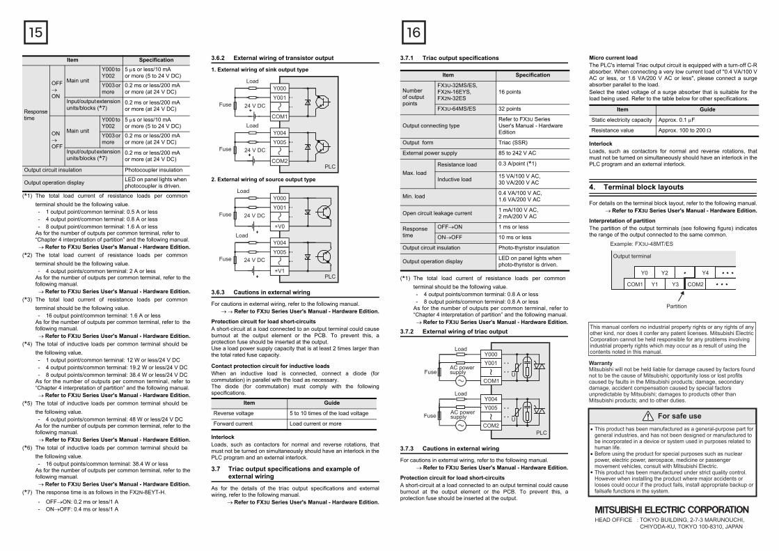
(*1) The total load current of resistance loads per commonterminal should be the following value.- 1 output point/common terminal: 0.5 A or less- 4 output point/common terminal: 0.8 A or less- 8 output point/common terminal: 1.6 A or less
As for the number of outputs per common terminal, refer to “Chapter 4 interpretation of partition” and the following manual.Refer to FX3U Series User's Manual - Hardware Edition.
(*2) The total load current of resistance loads per commonterminal should be the following value.- 4 output points/common terminal: 2 A or less
As for the number of outputs per common terminal, refer to thefollowing manual.Refer to FX3U Series User's Manual - Hardware Edition.
(*3) The total load current of resistance loads per commonterminal should be the following value.- 16 output point/common terminal: 1.6 A or less
As for the number of outputs per common terminal, refer to thefollowing manual.Refer to FX3U Series User's Manual - Hardware Edition.
(*4) The total of inductive loads per common terminal should bethe following value.- 1 output point/common terminal: 12 W or less/24 V DC- 4 output points/common terminal: 19.2 W or less/24 V DC- 8 output points/common terminal: 38.4 W or less/24 V DC
As for the number of outputs per common terminal, refer to“Chapter 4 interpretation of partition” and the following manual.Refer to FX3U Series User's Manual - Hardware Edition.
(*5) The total of inductive loads per common terminal should bethe following value.- 4 output points/common terminal: 48 W or less/24 V DC
As for the number of outputs per common terminal, refer to thefollowing manual.Refer to FX3U Series User's Manual - Hardware Edition.
(*6) The total of inductive loads per common terminal should bethe following value.- 16 output points/common terminal: 38.4 W or less
As for the number of outputs per common terminal, refer to thefollowing manual.Refer to FX3U Series User's Manual - Hardware Edition.
(*7) The response time is as follows in the FX2N-8EYT-H.
- OFFON: 0.2 ms or less/1 A- ONOFF: 0.4 ms or less/1 A
Responsetime
OFFON
Main unit
Y000 to Y002
5 s or less/10 mA or more (5 to 24 V DC)
Y003 or more
0.2 ms or less/200 mA or more (at 24 V DC)
Input/output extension units/blocks (*7)
0.2 ms or less/200 mA or more (at 24 V DC)
ONOFF
Main unit
Y000 to Y002
5 s or less/10 mA or more (5 to 24 V DC)
Y003 or more
0.2 ms or less/200 mA or more (at 24 V DC)
Input/output extension units/blocks (*7)
0.2 ms or less/200 mA or more (at 24 V DC)
Output circuit insulation Photocoupler insulation
Output operation display LED on panel lights when photocoupler is driven.
Item Specification
3.6.2 External wiring of transistor output1. External wiring of sink output type
2. External wiring of source output type
3.6.3 Cautions in external wiring
For cautions in external wiring, refer to the following manual. Refer to FX3U Series User's Manual - Hardware Edition.
Protection circuit for load short-circuitsA short-circuit at a load connected to an output terminal could causeburnout at the output element or the PCB. To prevent this, aprotection fuse should be inserted at the output.Use a load power supply capacity that is at least 2 times larger thanthe total rated fuse capacity.
Contact protection circuit for inductive loadsWhen an inductive load is connected, connect a diode (forcommutation) in parallel with the load as necessary.The diode (for commutation) must comply with the followingspecifications.
InterlockLoads, such as contactors for normal and reverse rotations, thatmust not be turned on simultaneously should have an interlock in thePLC program and an external interlock.
3.7 Triac output specifications and example of external wiring
As for the details of the triac output specifications and externalwiring, refer to the following manual.
Refer to FX3U Series User's Manual - Hardware Edition.
Item Guide
Reverse voltage 5 to 10 times of the load voltage
Forward current Load current or more
PLC
Load
24 V DCFuse
Y000
Y001
COM1Load
24 V DCFuse
Y004
Y005
COM2
PLC
Load
24 V DCFuse
Y000
Y001
+V0Load
24 V DCFuse
Y004
Y005
+V1
3.7.1 Triac output specifications
(*1) The total load current of resistance loads per commonterminal should be the following value.- 4 output points/common terminal: 0.8 A or less- 8 output points/common terminal: 0.8 A or less
As for the number of outputs per common terminal, refer to“Chapter 4 interpretation of partition” and the following manual.Refer to FX3U Series User's Manual - Hardware Edition.
3.7.2 External wiring of triac output
3.7.3 Cautions in external wiring
For cautions in external wiring, refer to the following manual.Refer to FX3U Series User's Manual - Hardware Edition.
Protection circuit for load short-circuitsA short-circuit at a load connected to an output terminal could causeburnout at the output element or the PCB. To prevent this, aprotection fuse should be inserted at the output.
Item Specification
Number of output points
FX3U-32MS/ES,FX2N-16EYS,FX2N-32ES
16 points
FX3U-64MS/ES 32 points
Output connecting typeRefer to FX3U Series User's Manual - Hardware Edition
Output form Triac (SSR)
External power supply 85 to 242 V AC
Max. loadResistance load 0.3 A/point (*1)
Inductive load 15 VA/100 V AC, 30 VA/200 V AC
Min. load 0.4 VA/100 V AC, 1.6 VA/200 V AC
Open circuit leakage current 1 mA/100 V AC, 2 mA/200 V AC
Response time
OFFON 1 ms or less
ONOFF 10 ms or less
Output circuit insulation Photo-thyristor insulation
Output operation display LED on panel lights when photo-thyristor is driven.
PLC
U
U
Load
FuseAC powersupply
Fuse
Load
AC powersupply
Y000Y001
COM1
Y005Y004
COM2
Micro current loadThe PLC's internal Triac output circuit is equipped with a turn-off C-Rabsorber. When connecting a very low current load of "0.4 VA/100 VAC or less, or 1.6 VA/200 V AC or less", please connect a surgeabsorber parallel to the load.Select the rated voltage of a surge absorber that is suitable for theload being used. Refer to the table below for other specifications.
InterlockLoads, such as contactors for normal and reverse rotations, thatmust not be turned on simultaneously should have an interlock in thePLC program and an external interlock.
4. Terminal block layouts
For details on the terminal block layout, refer to the following manual.Refer to FX3U Series User's Manual - Hardware Edition.
Interpretation of partitionThe partition of the output terminals (see following figure) indicatesthe range of the output connected to the same common.
Item Guide
Static electricity capacity Approx. 0.1 F
Resistance value Approx. 100 to 200
Y0
Partition
Output terminal
Example: FX3U-48MT/ES
Y2
COM1 Y1 COM2Y3
Y4
This manual confers no industrial property rights or any rights of any other kind, nor does it confer any patent licenses. Mitsubishi Electric Corporation cannot be held responsible for any problems involving industrial property rights which may occur as a result of using the contents noted in this manual.
WarrantyMitsubishi will not be held liable for damage caused by factors found not to be the cause of Mitsubishi; opportunity loss or lost profits caused by faults in the Mitsubishi products; damage, secondary damage, accident compensation caused by special factors unpredictable by Mitsubishi; damages to products other than Mitsubishi products; and to other duties.
For safe useThis product has been manufactured as a general-purpose part for general industries, and has not been designed or manufactured to be incorporated in a device or system used in purposes related to human life.Before using the product for special purposes such as nuclear power, electric power, aerospace, medicine or passenger movement vehicles, consult with Mitsubishi Electric.This product has been manufactured under strict quality control. However when installing the product where major accidents or losses could occur if the product fails, install appropriate backup or failsafe functions in the system.
HEAD OFFICE : TOKYO BUILDING, 2-7-3 MARUNOUCHI, CHIYODA-KU, TOKYO 100-8310, JAPAN