Embed Size (px)
Citation preview

Sidekick Basic Kit for Arduino V2
Introduction
The Arduino Sidekick Basic Kit is designed to be used with your Arduino / Seeeduino / Seeeduino ADK / Maple Lilypad or any MCU board. It contains everything needed for a first-time user to connect his/her computer to an Arduino. It includes many of the most popular accessories for DIY projects : like Breadboard, Jumper wires, Color LEDs, Resistors, Buzzer, etc. All of these coming with its own handy box are easy transport and minimal clutter.

Kit Contents
1. Breadboard x 1 2. Green LED x 5 3. Red LED x 5 4. RGB Common Anode LED x 1 5. Ceramic Capacitor(10nF x 10+100nF x 10) 6. Aluminum capacitor(100uF x 5) 7. Resistor(330R x 10+1k x 10+10k x 10) 8. Tilt switch x 1 9. Thermistor x 1 10. Photo resistor x 1 11. Diode x 1 12. Buzzer x 1 13. Button x 5 14. Switch x 5 15. Mini Servo x 1 16. Potentiometer with knob x 1 17. Breadboard jumper wire x 25(5x long, 20 x short) Breadboard x 1 18. Box x 4

Basic Electronics Refresher
Current and Voltage
Current is the rate of flowing electric charge in a conductor. Voltage is the potential difference (electric driving force) applied between two points to conduct current. Current is expressed in terms of Amperes (A) and Voltage is in terms of Volts (V).
Resistor
Resistors are obstacles of the flowing current in a conductor. They are used to limit the flow of current to an electronic device like lamp. The resistance to the flowing current is expressed in Ohms (Ω).They are divided into Fixed resistor and variable resistor (POT) .
Connecting Resistors
Resistors can be connected in two different types: In parallel or in series with each other.
Resistors In Series
When the resistors are connected in series, the total equivalent resistance will be equal to the sum of all the values of resistors in series.
Resistors In Parallel
In parallel, the reciprocal of the total equivalent resistance is equal to the sum of each resistor's reciprocal.
Ohm's Law
The relations among Current, Voltage and Resistance are governed by Ohm's Law - which states that "The current through a conductor (I Amperes) between two points is directly proportional to the potential difference or voltage across the two points (V Volts), and inversely proportional to the resistance between them (R Ohms)" i.e I = V / R. Hence V = IR or R = V / I. The following Ohm's Law triangle can be used to remember the relationship between V, I and R. The vertical line indicates multiplication operation and horizontal line indicates division operation.
eg: Hence to know current I, we divide V by R.
Breadboard

Breadboard is a prototyping device for electronic circuits. It is very useful to connect electronic components and to make a circuit without soldering. Breadboard consists of rows and columns of holes with metal contacts to insert components. The breadboard supplied with Arduino Sidekick Basic Kit is arranged of 2 X 30 five-hole columns and 4 X twenty five-hole rows. These holes are connected internally in a manner as illustrated below.
Fixed Resistors
The resistors supplied with Basic Kit are made of carbon and have fixed value type. The value of resistance is marked by the colored bands. You can get the value from the resistor color code sheet.
The first band indicates the first digit of the resistance value. The second band indicates the second digit. The third band indicates the multiplier value of the resistor. The fourth band denotes the Tolerance value.
Potentiometer (POT)
POT is a variable resistor whose resistance can be changed by rotating the knob. It has three terminals - the terminals on the ambilateral sides of the resistor are connected to ends of conductor which is made of resistive material. The middle terminal is connected to a slider which moves over the resistive material. The value of resistance changes proportionally to the position of the knob.

The
Therit. Th
Ligh
LDRalso minimCadm
Ligh
LEDand cphos
rmistors
rmistors are hey provide
ht Depend
R will changcalled photomum resistamium Sulph
ht Emittin
Ds emit will come in varphide, and b
special resie very usefu
dent Resis
ge the resistaocell. It offeance when ehide and can
ng Diodes
light up whrious colors by altering
istors whoseul and conve
tors (LDR
ance when ters maximuexposed to bn be connec
hen it is forwlike red, grthe proporti
e resistanceenient way t
R)
the intensityum resistancbright light
cted to the c
ward biasedreen and bluions of arse
e will be chato sense the
y of light face when the. It is made ircuit. It can
d. They are eue. LEDs arenic and pho
anged with t temperatur
alling on there is no lighup of photo
n be used as
encapsulatee made of gosphorus, di
the temperare differenc
em changesht falling ono sensitive ms a light sen
ed in a transgallium arseifferent colo
ature arounde.
. They are n it and givematerial likensing elemen
parent casinenide ors can be
d
es e nt.
ng

obtained. Monocolor LEDs have two leads Anode( +ve ) and Cathode (-ve). Tricolor LEDs have 4 Leads - one anode and 3 cathodes for each color.The LEDs can be used in display boards.
Switch
The switches are used to close or open the circuit. The switches supplied with Basic kit have two types - Push button switch and Slide Switch.
Push Button Switch
The circuit will be closed as long as you press the push button switch.
Slide Switch
Slide switch is a simple two positions switch. It can be used to open or close a circuit by setting it to appropriate position.
Tilt Switch

Tilt switch contains two terminals which are connected to the circuit , it closesthe circuit when it is tilted horizontally while opensthe circuit when tilted vertically.
Capacitors
Capacitors are used to store electric charge. They are classified into two different types: Electrolytic and Ceramic disc Capacitor. Capacitors are expressed in terms of micro Farads (uF).
Connecting the Capacitor
Capacitors can be connected in two types of arrangement in a circuit as shown below.
Capacitors In Series
The total equivalent capacitance, when two or more capacitors are connected in series with each other, is equal to the sum of the reciprocal of individual capacitance value.
Capacitors In Parallel
The total equivalent capacitance, when two or more capacitors connected in parallel, is equal to the sum of the individual capacitance.
Electrolytic Capacitors
Electrolytic Capacitors normally have small volume and large volume of capacitance. They are classified into polarized and non-polarized electrolytic capacitors. Metals like aluminum, tantalum , vanadium and bismuth are used to form anode and cathode foils.
Ceramic Disc Capacitors
The Ceramic Capacitors use ceramic dielectric with thin metal films as electrodes bonded to the ceramic. In the Disc type, capacitor silver is fixed on to both sides of ceramic to form conductor plates. The disc capacitors are used only for small value of capacitance.
Buzzer
A buzzer is an audio signaling device, which may be mechanical, electromechanical, or Piezoelectric. It produces various audio signal based on the oscillation of the material used in it. They are commonly used in alarms and timers.

Conn
The bAltervario
Diod
A diocondswitcdiodePN J
Biasi
Applpositsilicotermibiasi
Min
Servorobot
nect the lon
buzzer can rnatively, it ous tones an
de
ode is a semducting onlych in forwares are classi
Junction dio
ing a Diode
lying voltagtive supplyon diode aninals of a diing voltage
ni Servo
os are DC mts.
g pin to the
be connectecan be con
nd effects.
mi conductiny after the surd biased coified based
ode,zener di
e
ge to a diodey voltage is ad 0.3v for aiode, it is saexceeds bre
motors with
positive vo
ed to digitalnnected to an
ng material upply voltagondition andon the semiode,light em
e is called bapplied acro
a germaniumaid to be reveakdown vo
h gearing an
oltage, and t
l outputs, ann analog pu
that conducge is greaterd acts like aiconductingmitting diod
biasing a diooss the termm diode.Whverse biasedoltage.
nd feedback
the short pin
nd will emitulse-width m
cts current or than the b
an open switg material ande etc.
ode.The diominals and sthen a negatid. The diode
system.The
n to ground
t a tone whemodulation o
only in one arrier potentch when it nd can be u
ode gets forwtarts conducive voltage e gets dama
ey are used
d.
en the outpuoutput to ge
direction. Itntial. It actsis reverse b
used to fabri
ward biasedcting aboveis applied a
aged when t
in driving m
ut is high. enerate
t starts s like a closbiased. The cate,such as
d when a e 0.7v for a across the the reverse
mechanism
ed
s
of

Lessons
Hello World! : The Blinking LED
Circuit
Connect an LED to Digital Pin 8 as shown below. The 330 Ohm resistor limits the current flowing to the LED.

Program
Compile and upload the following sketch:
//Blink a LED connected to Digital Pin 8 via a 330 Ohm resitors. void setup() pinMode(8, OUTPUT); // Initialize Arduino Digital Pin 8 as output void loop() digitalWrite(8, HIGH); // Switch On LED delay(500); // Wait for half a second digitalWrite(8, LOW); // Switch Off LED delay(500); // Wait for half a second
Running LED display
Circuit
Connect 3 LEDs to Digital Pins 9, 10 and 11 via a 330 Ohms resistor each.
Program
Compile and upload the following sketch:
//Running LED display: Three LEDs connected to Digital Pin 9, 10 and 11. void setup() pinMode(9, OUTPUT); // Initialize Arduino Digital Pins 9 as output pinMode(10, OUTPUT); // Initialize Arduino Digital Pins 10 as output pinMode(11, OUTPUT); // Initialize Arduino Digital Pins 11 as output void loop() digitalWrite(9, LOW); digitalWrite(10, LOW); digitalWrite(11, HIGH); delay(250); // Wait for quarter of a second digitalWrite(9, LOW); digitalWrite(10, HIGH);

digitalWrite(11, LOW); delay(250); // Wait for quarter of a second digitalWrite(9, HIGH); digitalWrite(10, LOW); digitalWrite(11, LOW); delay(250); // Wait for quarter of a second
Talk to Arduino : Connecting a Pushbutton Switch
Circuit
Connect an LED to Digital Pin 8 as shown below. The 330 Ohm resistor limits the current flowing to the LED.
Connect one of Push button switch to Digital Pin 12, and another to GND via a 10K resistor.
Connect other end of Push button to +5V.
Program

Compile and upload the following sketch:
//Pushbutton switch demo: LED is connected to digital pin 8 and Pushbutton is connected to digital pin 12. //The LED glows when the button is pressed. char inputButtonState; void setup() pinMode(8, OUTPUT); // Initialize Arduino Digital Pins 8 as output for connecting LED pinMode(12,INPUT); // Initialize Arduino Digital Pins 12 as input for connecting Pushbutton void loop() inputButtonState = digitalRead(12); //Read the Pushbutton state. if (inputButtonState == HIGH) digitalWrite(8, HIGH); //Switch on LED else digitalWrite(8, LOW); //Switch off LED
The above does demonstrate how to send a signal to the Arduino. In fact, you can achieve the same goal without the Arduino. Just press the button to close the circuit, then, let's flip the HIGH/LOW values as follows:
void loop() inputButtonState = digitalRead(12); //Read the Pushbutton state. if (inputButtonState == HIGH) digitalWrite(8, LOW); //Switch on LED else digitalWrite(8, HIGH); //Switch off LED
The LED now lights with the circuit open and switches off with the circuit closed.
3 Analog: POT
Circuit
Connect anode of LED to PWM Pins via a 220 Ohms resistor . Connect cathode of LED to GND Pin. Mount the Pot in the bread board.

Connect the right leg of the Pot to +5v. Connect the middle leg of the Pot to any of the Analog input pins(0-5). Connect left leg of the Pot to the Ground Terminal.
Program
Connect LED annode to digital pin 5 (instead of 5V). Compile and Upload the following sketch:
//Varying the brightness of the LED using a Pot int value=0; int mval; void setup() pinMode(5, OUTPUT); void loop() value=analogRead(A1); //read analog value from input A1 // PWM output given to the LED mval = map(value, 0, 1023, 0, 100); analogWrite(5,mval);

4 Rainbow On Desk: Tricolor LED
Circuit
RGB LED supplied with the basic kit is common anode type. The longest lead is anode. Other three leads are cathodes for Red, Green and Blue respectively.
Connect RGB cathodes LEDs to Digital Pins 9, 10 and 11 via a 330 Ohms resistor each. Connect Anode to +5v
Program
Compile and upload the following sketch:
void setup() void loop()

for(int b = 0 ; b <= 255; b=b+5) for(int g = 0 ; g <= 255; g=g+5) for(int r= 0 ; r <= 255; r=r+5) analogWrite(9, b); analogWrite(10, g); analogWrite(11, r); delay(10);
5 Music:
Circuit
Connect buzzer anode to Digital Pins 11. Connect buzzer negative to GND

Program
Compile and upload the following sketch:
#define NOTE_D0 98 #define NOTE_D1 294 #define NOTE_D2 330 #define NOTE_D3 350 #define NOTE_D4 393 #define NOTE_D5 441 #define NOTE_D6 495 #define NOTE_D7 556 #define NOTE_DL1 147 #define NOTE_DL2 165 #define NOTE_DL3 175 #define NOTE_DL4 196 #define NOTE_DL5 221 #define NOTE_DL6 248 #define NOTE_DL7 278 #define NOTE_DH1 589 #define NOTE_DH2 661
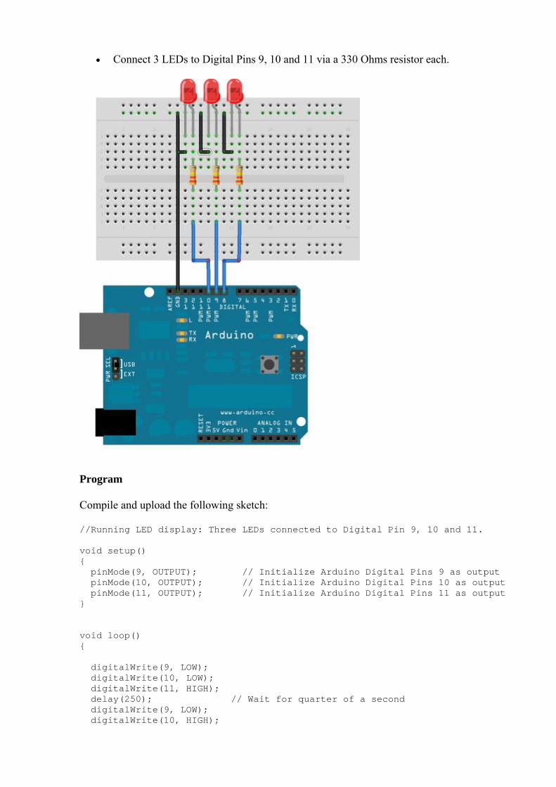
#define NOTE_DH3 700 #define NOTE_DH4 786 #define NOTE_DH5 882 #define NOTE_DH6 990 #define NOTE_DH7 112 #define WHOLE 1 #define HALF 0.5 #define QUARTER 0.25 #define EIGHTH 0.125 #define SIXTEENTH 0.625 // notes in the melody: int tune[] = NOTE_D0,NOTE_D1,NOTE_D2,NOTE_D3,NOTE_D4,NOTE_D5,NOTE_D6,NOTE_D7, NOTE_DL1,NOTE_DL2,NOTE_DL3,NOTE_DL4,NOTE_DL5,NOTE_DL6,NOTE_DL7, NOTE_DH1,NOTE_DH2,NOTE_DH3,NOTE_DH4,NOTE_DH5,NOTE_DH6,NOTE_DH7, ; /* note durations: 1 = one note*/ float duration[]= 1,1,1,1,1,1,1,1, 1,1,1,1,1,1,1,1,1,1,1,1,1,1,; int length; int tonePin=11; // buzzer pin void setup() Serial.begin(9600); pinMode(tonePin,OUTPUT); // initialize the digital pin as an output length = sizeof(tune)/sizeof(tune[0]); void loop() for(int x=1;x<length;x++) tone(tonePin,tune[x]); delay(400*duration[(x%100)]); // to distinguish the notes, set a minimum time between them. noTone(tonePin); // stop the tone playing:
6 Mini Servo:
Circuit
Connect the Red colored wire of the servo motor to +5v supply. Connect the black colored wire of the servo to ground. Connect the yellow wire of the servo to any of the PWM pin in the Arduino. Connect the right leg of the Pot to +5v. Connect the middle leg of the Pot to any of the Analog input pins(0-5). Connect the left leg of the Pot to the Ground Terminal.

Program
Compile and Upload the following sketch:
// Controlling a servo position using a potentiometer (variable resistor) // by Michal Rinott <http://people.interaction-ivrea.it/m.rinott> #include <Servo.h> Servo myservo; // create servo object to control a servo int potpin = 1; // analog pin used to connect the potentiometer int val; // variable to read the value from the analog pin void setup() myservo.attach(5); // attaches the servo on pin 5 to the servo object Serial.begin(19200); // some servos doesn't work without Serial void loop() val = analogRead(potpin); // reads the value of the potentiometer (value between 0 and 1023) val = map(val, 0, 1023, 0, 179); // scale it to use it with the servo (value between 0 and 180)

myservo.write(val); // sets the servo position according to the scaled value delay(15); // waits for the servo to get there
Usage
There is a solderless breadboard, therefore, there is no need to purchase a soldering iron or to learn how to solder.
There are plenty of jumper wires which are long and flexible with rigid tips. These jumper wires are much better than the fixed length solid wire jumpers of the past.
There are plenty of LEDs and resistors for your first project, including a RGB LED which is a single LED package with three primary colored LEDs inside. By adjusting the intensity of the different primary colored LEDs, the colors will mix together and produce all the colors of the rainbow.
There is even an educational how-to card to read the resistor values. The tilt switch is a very simple device with a small metal ball inside. If the device is tilted
to one side the metal ball will touch electrical contacts. This sensor is useful for a variety of projects like a DIY burglar alarm.
The thermistor is useful for projects when you want to detect the temperature. The photo resistor can detect light,and it works with light bulbs and sunlight. Photo
resistors are commonly used for detecting when it's dark and turning lights on at night. The buzzer in the kit works especially well for playing the Mario Brothers theme song. There is a Mini Servo motor. You can use it to open and close a deadbolt, lightswitch or
valve. You could even use it to make a mini catapult. The potentiometer is a great input device. You can use it to control the angle of the Servo
arm or the intensity of LEDs.
Support
If you have questions or other better design ideas, you can go to our forum or wish to discuss.