Embed Size (px)
Citation preview
DOLE REFRIGERATING COMPANY
1420 Higgs Road • Lewisburg, Tennessee 37091 Phone (931) 359-6211 1-800-251-8990
www.doleref.com
SIDMAN – 105000 OPERATION & MAINTENANCE MANUAL
SIDE RAM FREEZER MODEL 105000
July 2002 THIS REVISION INCLUDES SPECIAL SUPPLEMENTS ON:
• AN ELECTRICALLY CONTROLLED HYDRAULIC/INJECTOR FED REFRIGERATION SYSTEM – SINGLE AND DUAL FREEZERS • A “10 PSI” PRODUCT PRESSURE FREEZER OPTION
2
SIDE RAM FREEZER
Table of Contents
Page
Table of Contents 2 List of Tables 3 List of Illustrations 4 1.0 Introduction 5 2.0 Description 5
2.1 Basic Configuration 7 2.2 Options Offered 7 2.3 Frame 8 2.4 Pressure Plate 8 2.5 Contact Freezer Plates 8 2.6 Hydraulic System 9 2.7 Refrigeration System 10 2.8 Cabinet 10
3.0 Installation 17 4.0 Operation 17
4.1 Loading the Freezer 17 4.2 Operating the Hydraulic System 20 4.3 Operating the Refrigeration System 21 5.0 Maintenance 21
5.1 Cabinet Maintenance 21 5.2 Refrigerant Hose Maintenance 21 5.3 Freezer Plate Maintenance 22
3
5.4 Hydraulic System Maintenance 22 5.4.1 Manual Control and Relief Valves 22 5.4.2 Hydraulic Actuator Maintenance 28 5.4.3 Hydraulic Flow Divider Maintenance 29 5.5 Lifting Bolt Maintenance 29
Special Supplement No. 1 An Electrically Controlled Hydraulic/Injector Fed Refrigeration System
S1.1 Control System 31 S1.2 Hydraulic System 34 S1.3 Refrigeration System 34
Special Supplement No. 2 A Dual Freezer Electrically Controlled Hydraulic/Injector Fed Refrigeration System
S2.1 Control System 40 S2.2 Hydraulic System 45
S2.3 Refrigeration System 45 Special Supplement No. 3 A 10 PSI Option Freezer
S3.1 Frame 47 S3.2 Pressure Plate 47 S3.3 Hydraulic System 47 S3.3.1 Hydraulic Relief Valve Adjustment 49 S3.362 Hydraulic Actuator Maintenance 49
Appendix
Table 1 – Relief Valve Settings – 48” Plates (15psi Pressure) 54 Table 2 – Relief Valve Settings – 55” & 57” Plates (15psi Pressure) 55 Table 3 – Relief Valve Settings – 60” Plates (15psi Pressure) 56 Table 4 – Internal Volumes – 48” Aluminum Plates (Lightweight) 57 Table 4HW – Internal Volumes – 48” Aluminum Plates (Heavyweight) 58 Table 5 – Internal Volumes – 48” Steel Plates 59 Table 6 – Internal Volumes – 55” & 57” Steel Plates 60 Table 7 – Internal Volumes – 60” Aluminum Plates (Lightweight) 61 Table 7HW – Internal Volumes – 60” Aluminum Plates (Heavyweight) 62 Table 8 – Cooling Rate & Refrigeration Capacity vs. Plate Size & Product Thickness 63 Table 9 – Parts List 66
Limited Warranty 67
4
LIST OF ILLUSTRATIONS
Figure 1 – Freezer Assembly 6 Figure 2 – Frame Assembly 11 Figure 3 – Pressure Plate Assembly 12 Figure 4 – Aluminum Plate Configuration 13 Figure 5 – Steel Plate Configuration 14 Figure 6 – Hydraulic System Schematic 15 Figure 7 – Refrigerant Feed Methods 16 Figure 8 – Cabinet (with doors) 18 Figure 9 – Cabinet (with curtains) 19 Figure 10- Hydraulic Control Valve Block 24 Figure 11- Hydraulic Relief Valves 25 Figure 12- Hydraulic Cylinders 26 Figure 13- Cylinder Repair Parts 27 Figure 14- Special Injector-Fed System 32 Figure 15- Operator Panel and System Schematic 33 Figure 16- Freezer Control Schematic & Wiring Diagram 35 Figure 17- Hydraulic Power Unit 37 Figure 18- Hydraulic Flow Diagram 38 Figure 19- Refrigeration System 39 Figure 22- Surge Drum/Heat Exchanger Assy 41 Figure 23- Electrical Schematic—Dual Freezers 42 Figure 24- Wiring Diagram—Freezer Control Panel 43 Figure 25- Freezer Control Panel-—Dual Freezers 44 Figure 26- Hydraulic Flow Diagram--Dual Freezers 46 Figure 27- Pressure Plate (10 psig option) 48 Figure 28- Cylinder Construction Features (10 psig option) 50 Figure 29- Cylinder Replacement Parts (10 psig option) 50
5
1.0 INTRODUCTION This manual describes the Dole Double Contact Plate Side Ram Freezer Model 105000, the various configurations available, and their operation and maintenance. The Side Ram Freezer, so named because of the two "rams", or hydraulic actuators, used to raise and lower the freezer plates, is compatible with R22, R717, R404A, and R507 refrigeration systems. The Side Ram Freezer is available in a variety of sizes (type of plates, size of plates, number of freezing stations, product spacing) and can be furnished with or without a cabinet. Each unit is completely assembled and ready for tie-in to an external refrigeration and hydraulic system. The Sections that follow discuss in some detail the various base configurations as well as options that are available. 2.0 DESCRIPTION The Model 105000 Freezer, supported by an external refrigeration system, provides a means of freezing products through direct contact, or conduction, the most efficient of heat transfer methods. Since products to be frozen are held firmly between cold plates, the thickness and flatness of the frozen product can be controlled. The space between any two adjacent plates is called a Station. Figure 1 illustrates the various elements of the typical Side Ram Freezer. In general, a freezer consists of a steel Frame that provides a means of housing the various elements of the freezer and resisting the severe structural stresses encountered during the freezing process. A Pressure Plate is the main structural component that provides a means of uniformly lifting and lowering the plates as required. Each plate is attached to the Pressure Plate and/or the plates directly above and below by Lifting Bolts. Spacers provide a means of limiting the space between adjacent plates during freezing. A Hydraulic System, consisting of a Control Valve, a Flow Divider, two Actuators, and interconnecting piping, provides the directional force required to lift the plates to the "Open" (loading or unloading) position and to lower the plates to the "Closed" (or freezing) position while maintaining sufficient pressure on the product to enhance efficient heat transfer. The freezer's Refrigeration System consists of a Liquid Header, a Suction Header, and individual carbon-impregnated teflon-lined stainless steel braided hoses to the liquid and suction fittings on each Plate. At the present, Dole does not offer a "high-Side" refrigeration system. However, Dole Engineering personnel are ready to recommend the system capacity needed to
6
7
efficiently utilize a specific freezer. Dole does offer an external Hydraulic Power Unit, which is available in a "Manual" or an "Automatic" version. Should a Dole Hydraulic Power Unit be used to support the operation of a Side Ram freezer, an Operational and Maintenance Manual on the appropriate unit will be provided. The Side Ram Freezer is offered with or without an insulated "Cabinet". Cabinets are available with doors or Roll-up Curtains. Each of the various elements of the Side Ram Freezer is discussed in the material that follows. 2.1 Basic Configuration The basic Freezer configuration consists of a Zinc-Metallized steel Frame, a Pressure Plate, Plates (number of Plates equals number of stations plus one), a Liquid Header, a Suction Header, Lifting Bolts, Spacers and Guides, individual Liquid and Suction Hoses to each Plate, and a Hydraulic System consisting of two Actuators, a Flow Divider, a Control Valve, and interconnecting plumbing. Side Ram Freezers are identified as follows: a freezer made up of 48 inch x 72 inch plates that comprise 12 stations would be identified as a Model 4872-12, where "48" refers to the width of the Plates in inches, "72" refers to the length of the Plates in inches, and "12" refers to the number of freezing stations. In addition, the refrigerant used and the method of feeding that refrigeration is also appended to the Model number. For example, if the above freezer were to be fed by re-circulated Ammonia, the Model number becomes 4872-12RA, where the "RA" refers to the refrigerant and the method of feed. In the event that the freezer was to be fed by a full-flooded freon system, the Model number would be 4872-12FFR. 2.2 Options Offered The Hot Gas Defrost option provides for a one inch Thredolet fitting on the Suction Header for the Hot Gas Supply and a 1-1/4 inch Thredolet fitting on the Liquid Header for Hot Gas Return. The Sea Rail option is offered for units installed on board a ship to restrain product trays when loading and unloading the freezer. This option is also offered with stops on one side of the Plates in cases where loading (and/or unloading) is to be accomplished from only one side of the freezer. The Side Ram Freezer requires an external 1000 psi Hydraulic System to position Plates. Such a system is capable of producing a pressure of 3 to 5 psi on the product during freezing. The exact pressure on the product is determined by the size of the plates. Note: A “10 psi” freezer is also offered as an option. It is described in the SPECIAL SUPPLEMENT. Dole can provide a separate Hydraulic Power Unit to support
8
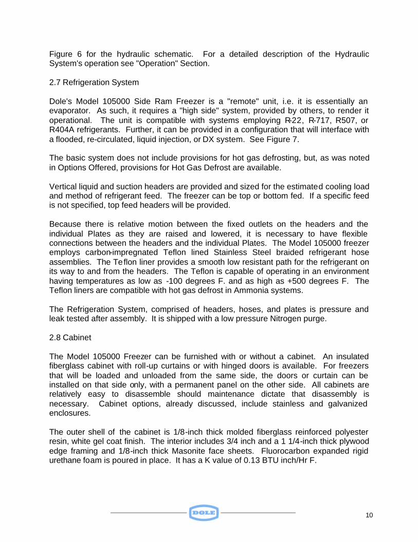
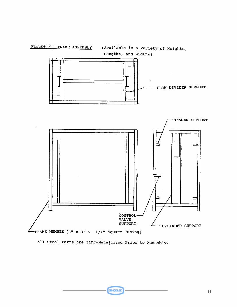
freezer operation. Should a Dole power unit be used, a separate Operations and Maintenance Manual will be provided. Special customer requests, such as a CIP (Clean-In-Place) Header and Nozzles, or individual Isolation Valves in each Liquid and Suction line to the Plates, or an electrically controlled (as opposed to manual) hydraulic valve are also available. 2.3 Frame The Model 105000 Frame has been designed to be compatible with stresses imposed in a typical freezing operation, either shore side or on board ship. Rugged three-inch by 1/4-inch wall square steel tubing provides the basic structure in which the contact freezer plates will operate. See Figure 2. Two vertical 2.5”,2.5”,.25” steel angles provide a means of supporting the two hydraulic actuators (or "rams") that are used to position the freezer plates. These channels provide an efficient means for transferring vertical loads into the frame. See SPECIAL SUPPLEMENT for structural details of the “10 psi” option freezer. Frame height is normally 85 1/4 inches, but other heights are available to meet specific customer requirements. All portions of the Frame, an all-welded assembly, are zinc-metallized after assembly to provide effective corrosion resistance. 2.4 Pressure Plate The function of the Pressure Plate is to provide a means of lifting and lowering the nest of freezer plates and product during loading, unloading and freezing. It also provides a means of keeping a minimum pressure on the product during freezing. The basic Pressure Plate consists of a four inch x 1/4 inch square steel tubing that forms a strong "spine", or "backbone', with 1/2 thick steel plates serving as ribs. See Figure 3. See SPECIAL SUPPLEMENT for structural details of the Pressure Plate for the “10 psi” option freezer. The Pressure Plate, like the Frame, is zinc-metallized after assembly to provide for effective corrosion resistance. 2.5 Contact Freezer Plates Contact Freezer Plates transfer heat from a product to refrigerant flowing through the Plates touching the product. It is extremely important that the Plates contact the top as
9
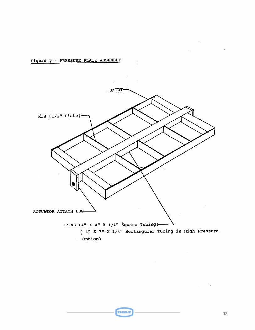
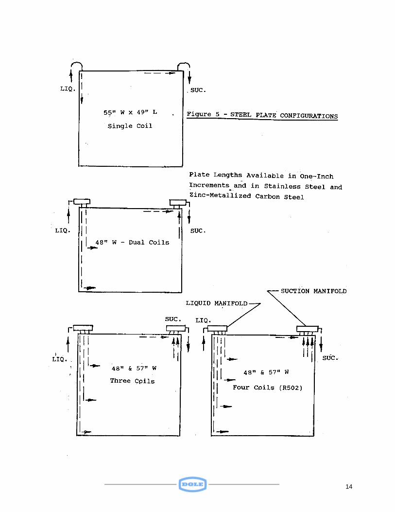
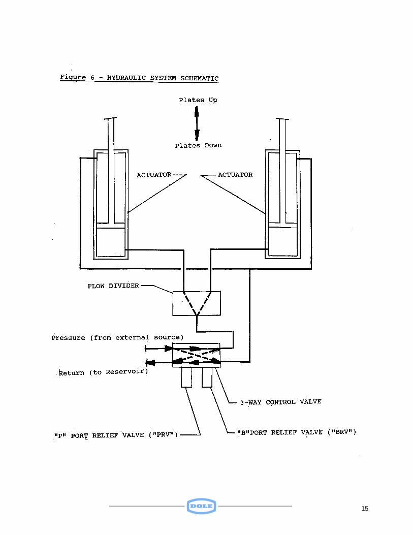
well as the bottom of the product since the heat transferred during freezing is a result of conduction, the most efficient method of transferring heat. Dole Plates are available in a large variety of sizes and materials. Standard widths for Aluminum Plates are 48 and 60 inches. Zinc-metallized Steel Plates are normally available in 46, 55, and 57-inch widths. Stainless Steel Plates are normally available in the same widths as the Zinc-Metallized Plates. Whereas Aluminum Plates are fabricated from 6063-T5 Aluminum extrusions, Steel Plates are fabricated from 16-gauge sheet with internal coils of 3/4 inch square tubing. A 48 inch wide Aluminum Plate is fabricated from two 20 inch wide and one 8-inch wide extrusions, cut to the proper length, and seam welded together. The 60-inch Aluminum Plate consists of three 20-inch wide extrusions seam welded throughout their length. See Figure 4 for the several Aluminum Plate configurations offered. Refrigerant manifolds for Aluminum Plates are made from aluminum extrusions, which are cut to length, machined, and welded to the Plate extrusions on each end. An aluminum fitting is then welded to each manifold (Liquid and Suction). The completed assembly is then pressure and leak tested. A Steel Plate consists of a Pan, a Cover, an internal coil (or coils depending upon the length of the plate), and external liquid and suction manifolds. The coil(s) is pressurized and leak tested. The completed coil(s) is assembled into the Pan. The Pan and Cover are then seam welded together with corners hand welded. Liquid and Suction manifolds are welded to the end of the coil(s). After zinc-metallizing, the assembly is partially filled with a thermofilm heat transfer agent, a vacuum is pulled on the assembly and subsequently sealed in. See Figure 5 for steel plate configurations offered. 2.6 Hydraulic System The basic Model 105000 Freezer is designed for operation with an external 1000-psi hydraulic power source. Such a source can be a central hydraulic system, which is part of a customer's plant, or it may be a unit dedicated to the operation of one or more of Dole's Freezers. See SPECIAL SUPPLEMENT for description of the Hydraulic System for the “10 psi” option freezer. Dole offers hydraulic power units for use with their freezers in a variety of configurations. The units can be operated manually or automatically. The Manual unit must be turned on and off as needed. The Automatic unit is turned on and off by means of a pressure monitor. Units are available in a variety of voltages and with a 30-gallon or a 50-gallon reservoir. The portion of the Hydraulic System supplied as part of a Side Ram Freezer includes the following: a 3-position (up- down-neutral) manual control valve, two relief valves, a flow divider, two hydraulic actuators, and interconnecting stainless steel plumbing. See
10
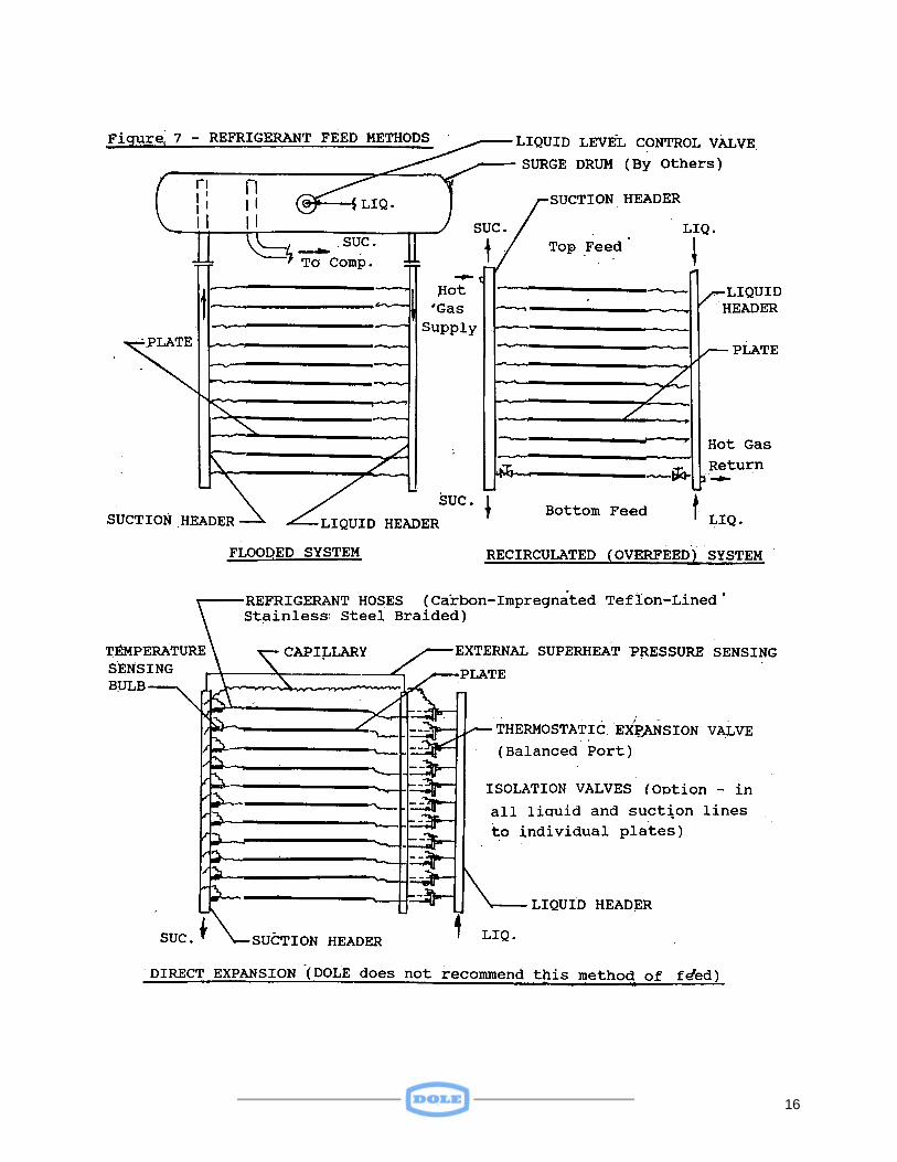
Figure 6 for the hydraulic schematic. For a detailed description of the Hydraulic System's operation see "Operation" Section. 2.7 Refrigeration System Dole's Model 105000 Side Ram Freezer is a "remote" unit, i.e. it is essentially an evaporator. As such, it requires a "high side" system, provided by others, to render it operational. The unit is compatible with systems employing R-22, R-717, R507, or R404A refrigerants. Further, it can be provided in a configuration that will interface with a flooded, re-circulated, liquid injection, or DX system. See Figure 7. The basic system does not include provisions for hot gas defrosting, but, as was noted in Options Offered, provisions for Hot Gas Defrost are available. Vertical liquid and suction headers are provided and sized for the estimated cooling load and method of refrigerant feed. The freezer can be top or bottom fed. If a specific feed is not specified, top feed headers will be provided. Because there is relative motion between the fixed outlets on the headers and the individual Plates as they are raised and lowered, it is necessary to have flexible connections between the headers and the individual Plates. The Model 105000 freezer employs carbon-impregnated Teflon lined Stainless Steel braided refrigerant hose assemblies. The Teflon liner provides a smooth low resistant path for the refrigerant on its way to and from the headers. The Teflon is capable of operating in an environment having temperatures as low as -100 degrees F. and as high as +500 degrees F. The Teflon liners are compatible with hot gas defrost in Ammonia systems. The Refrigeration System, comprised of headers, hoses, and plates is pressure and leak tested after assembly. It is shipped with a low pressure Nitrogen purge. 2.8 Cabinet The Model 105000 Freezer can be furnished with or without a cabinet. An insulated fiberglass cabinet with roll-up curtains or with hinged doors is available. For freezers that will be loaded and unloaded from the same side, the doors or curtain can be installed on that side only, with a permanent panel on the other side. All cabinets are relatively easy to disassemble should maintenance dictate that disassembly is necessary. Cabinet options, already discussed, include stainless and galvanized enclosures. The outer shell of the cabinet is 1/8-inch thick molded fiberglass reinforced polyester resin, white gel coat finish. The interior includes 3/4 inch and a 1 1/4-inch thick plywood edge framing and 1/8-inch thick Masonite face sheets. Fluorocarbon expanded rigid urethane foam is poured in place. It has a K value of 0.13 BTU inch/Hr F.
11
12
13
14
15
16
17
Cabinet hardware includes heavy-duty hinges and cam-latches attached to steel plates. See Figures 8 and 9 for cabinet configurations offered. 3.0 INSTALLATION Freezers to be installed on shipboard should be leveled and the legs welded to the deck. Freezers to be installed in a shore-side facility can simply be moved into place, leveled with the use of shims and steel plates, and bolted to studs in the floor. Base plates can be provided with a freezer upon request. The external hydraulic system should be connected to the 3-way control valve by piping the pressure line to the "P" port on the valve and connecting the return line to the "T" (for Tank) port on the valve. Upon placing the Freezer in the desired position, final connections to the external source of refrigeration should be made. After subsequent leak testing, the system should be evacuated per standard procedures and charged with the appropriate refrigerant. See OPERATION Section for data on plate capacities. 4.0 OPERATION Loading and unloading the Freezer is a relatively simple operation. Assuming that the external refrigeration system has sufficient capacity to freeze the product in a specified period there is little that can go wrong and interfere with a successful freezing cycle. 4.1 Loading the Freezer For the most efficient operation, it is recommended that the plates be loaded as uniformly as possible, with the product distributed equally across each pla te. Packages of different thickness should not be placed in the same freezing station. In cases where only a portion of all the stations in a freezer are in use, care should be taken to prevent plates above or below the loaded stations from bowing as a result of product expansion during freezing. Bowing can be prevented by placing a spacer across the width (front to back) and near the center of the plates so that any load which might tend to cause a plate to bow would be transferred through such spacers to the pressure plate and/or to the bottom of the frame. It is recommended that a freezer be loaded with product from the bottom station up, i.e. if any stations are to be empty during freezing, they should be those above the loaded stations. Plates should be kept free of ice. Upon completion of a freezing cycle, the flow of refrigerant should be stopped, the product removed, and the doors (or curtains) left open to permit the ice to melt in preparation for the following freezing cycle. The Hot Gas Defrost option provides an excellent method of rapidly melting ice on plates.
18
19
20
4.2 Operating the Hydraulic System Prior to shipment, the hydraulic system was exercised as part of the assembly procedure, and as part of testing, to assure that operation of the system was smooth and free of air. Upon connection to an external hydraulic power source the system should be cycled up and down several times until smooth operation is observed. See Figure 6 for the Hydraulic System Schematic. With hydraulic pressure available to the control valve, placing the handle of the valve in the "Up" position will cause the plates to rise to the maximum open position. With the valve handle remaining in the Up position, the plates will stay up as long as system pressure is maintained. Placing the valve handle in "Neutral” will hold the plates where they were (up, down, or in an intermediate position) when the valve handle was so positioned. To lower the plates for freezing, place the valve handle in the "Down" position. To hold the plates in an intermediate position, place the handle in "Neutral". When the plates have been placed in the down, or freezing position, the valve handle should be left there throughout the freezing cycle. This is essential to assure that any additional internal pressure on the rod side of the hydraulic actuators, due to product expansion, can be relieved through the "BRV" relief valve in the control valve block. This valve will have been set, during factory assembly, to relieve at 1050 psi. See SPECIAL SUPPLEMENT for details on Relief Valve setting for the “10 psi” option freezer. The "PRV" Relief Valve in the Control Valve block will have been set, during factory assembly, to relieve at 975 psi to assure that pressure to the control valve will not exceed that value. See SPECIAL SUPPLEMENT for details on Relief Valve setting for the “10 psi” option freezer. A gear-type flow divider is provided to assure that the flow of hydraulic fluid to each cylinder is equal, thereby permitting smooth and even movement of the plates, regardless of any unbalanced loads in the system. Two 3-1/4 inch diameter foot-mounted hydraulic actuators, rated at 1500 psi operating pressure, are mounted on their respective cylinder support channels. See SPECIAL SUPPLEMENT for details on hydraulic actuators for the “10 psi” option freezer. The actuator stroke is dependent upon the number of stations in the freezer and the minimum and maximum openings of the plates. For example, a 15-station freezer with 2 1/2 inch and 3 1/2 inch minimum and maximum openings respectively, will require a working stroke of 15 inches. The actuators are bolted to the support angles and attached to the Pressure Plate by a Clevis and Pin arrangement.
21
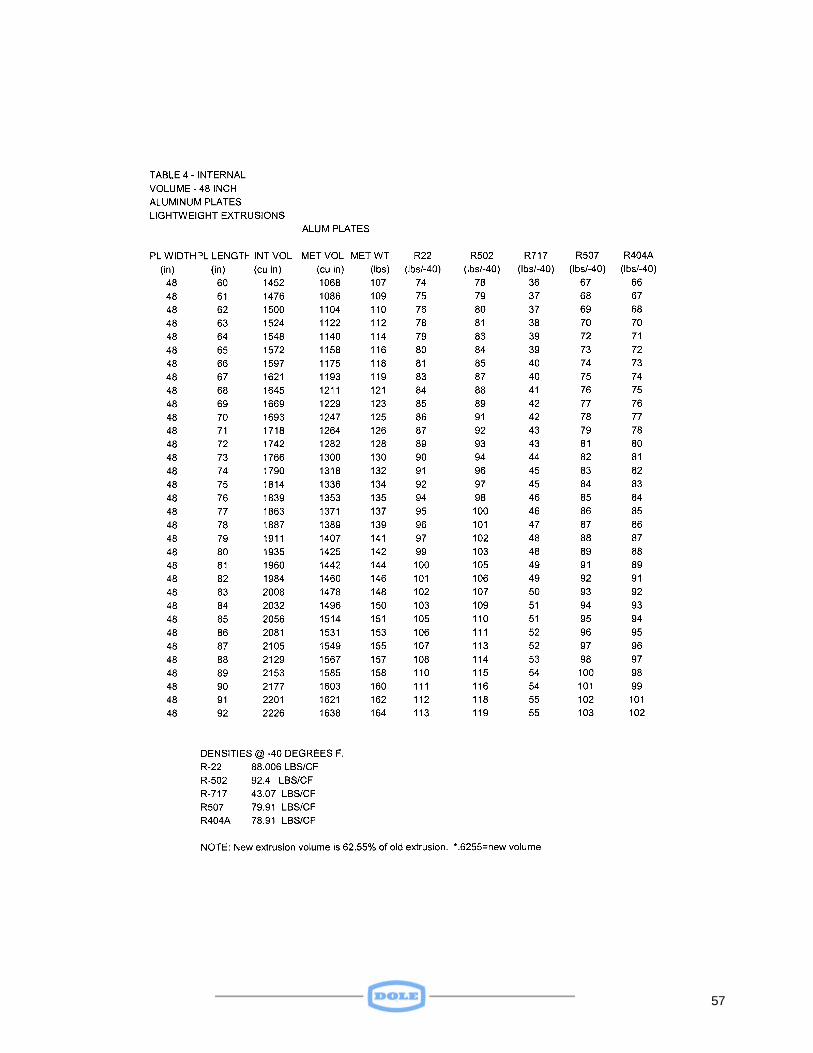
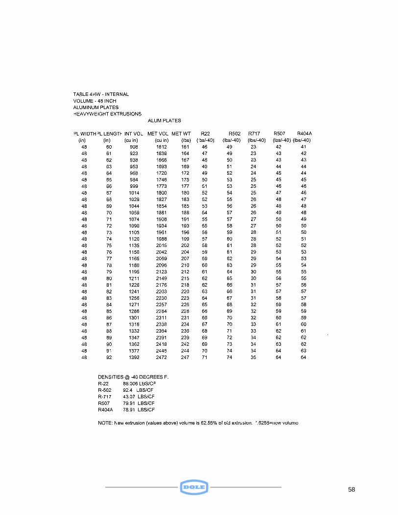
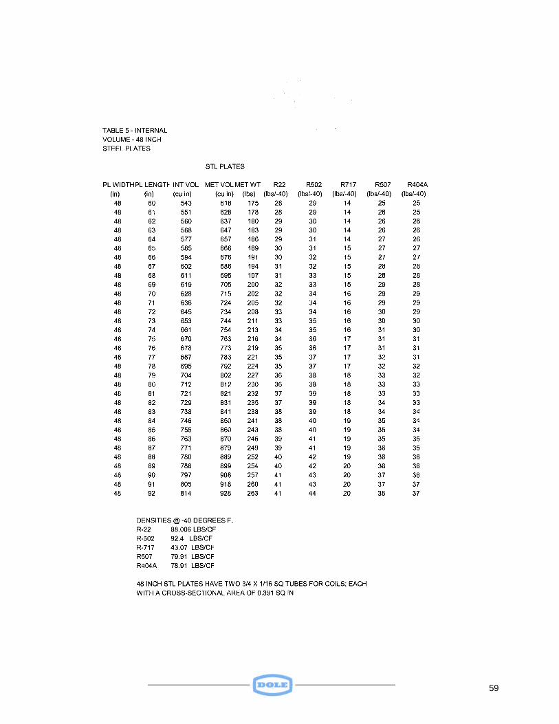
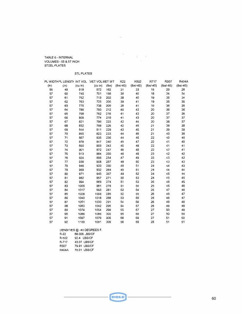
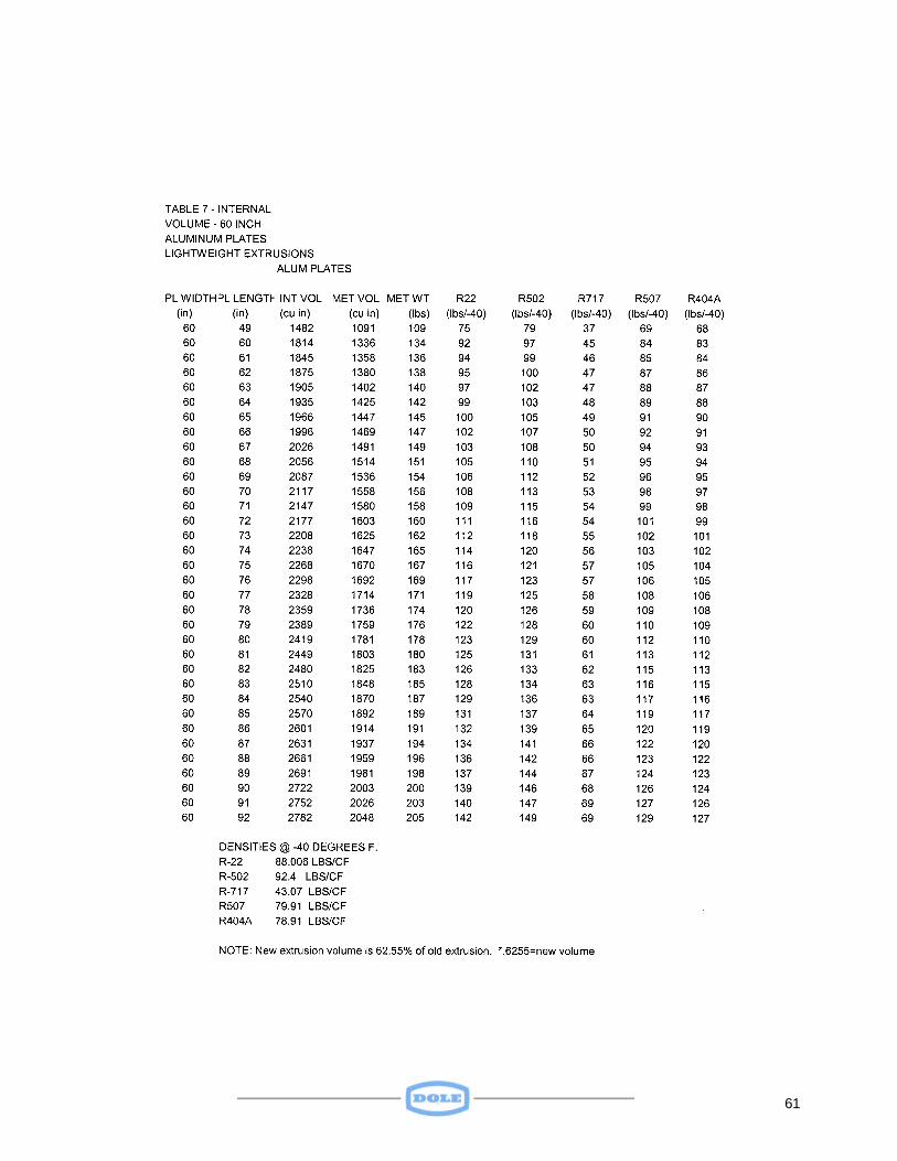
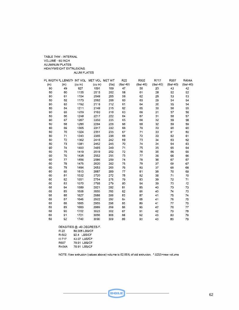
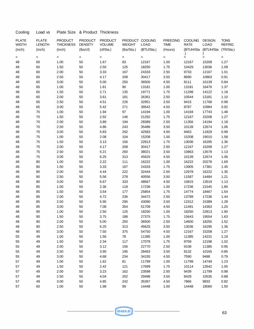
4.3 Operating the Refrigeration System The Model 105000 Freezer is essentially nothing more than an evaporator whose coils (plates) can be moved through small distances to provide heat transfer through conduction, as opposed to a less efficient method, i.e. convection. The freezer portion of the total refrigeration system consists of a liquid header, a suction header, several plates (evaporators), and interconnecting flexible hoses that carry the refrigerant to and from the plates. See Figure 7. The internal volumes of various sized plates are listed in the appendix in Tables 4, 5, 6, and 7. Cooling loads vs. plate size and product thickness are shown in Table 8. For the optimum operation, the plates should be kept as clear of frost as possible. Defrosting plates may be accomplished by closing the refrigerant feed and suction line valves and leaving the cabinet doors (or curtains) open. Defrosting may also be accomplished by using the hot gas (compressor discharge). Care should be taken in the design of any hot gas discharge system to prevent liquid flood back to the compressor. 5.0 MAINTENANCE The Model 105000 Freezer has been designed to provide years of trouble-free service. There are few moving parts and relatively unsophisticated maintenance should keep the unit in peak operating condition. 5.1 Cabinet Maintenance On freezers with cabinets and doors, check weekly to determine if there is a tendency for door gaskets to freeze to the doorjamb. Dow Corning Slipicone should be applied to the door gaskets if a tendency is noted. Lubricate the door hinges once a week via grease fittings provided in each hinge. 5.2 Refrigerant Hose Maintenance The Model 105000 refrigerant hoses should provide years of service. Care should be taken to see that hoses are relatively free of frost at the beginning of a freezing cycle. A stainless steel protective shroud has been provided to protect refrigerant hoses from catching or chafing against any sharp edges during freezer operation. Should it be necessary to remove this shroud for maintenance purposes, the shroud should be replaced prior to cycling the plates up and down to prevent any hose damage. If it becomes necessary to tighten a hose to eliminate a leak, care should be taken to avoid twisting the braid as this can kink the hose and weaken the Teflon liner. Should it
22
be necessary to remove and replace a hose, the following procedure should be followed: 1) Shut off the refrigerant to the freezer. 2) Pump refrigerant out of freezer and recover. 3) Isolate freezer from the refrigeration system by closing the suction valve. 4) Disconnect hose from header and plate. 5) Replace hose. 6) Pressurize and leak test. 7) Evacuate and open freezer to refrigeration System. 8) Add refrigerant to system if necessary. 5.3 Freezer Plate Maintenance Should it be necessary to remove or add freezer plates for repair or for a changeover in package freezing requirements, Dole engineering personnel may be contacted for assistance. The following procedure should be followed if it becomes necessary to remove or add a plate:
1) Disconnect hoses from plate in accordance with procedure presented in 5.2 Refrigerant Hose Maintenance.
2) Leave plates in loading (raised) position. 3) To provide working space for the removal of lifting bolts, insert blocks on the top of the eight spacers between the plate to be removed and its two adjacent plates. The blocks should be of such a size as to maintain the maximum open position between these plates.
4) Lower pressure plate to freezing position. 5) Remove the nuts from the eight lifting bolts, which pass through the plate to be
removed. 6) Raise the pressure plate to the loading position. 7) Remove plate from freezer. 8) To replace the plate, reverse the procedure. 5.4 Hydraulic System Maintenance Dole recommends using LUBRIPLATE hydraulic fluid in Side Ram Freezers, especially those enclosed in Cabinets, where the hydraulic fluid is exposed to severe cold. This fluid is compatible for use in systems with operating temperatures as low as -70 degrees F. 5.4.1 Manual Control and Relief Valves A 3-position manual control valve serves as the interface between the freezer and an external source of hydraulic power. As has been previously discussed, moving the valve handle "Up" will cause the plates to rise and open up to a loading or unloading position. Moving the handle "Down" will cause the plates to be lowered to the freezing
23
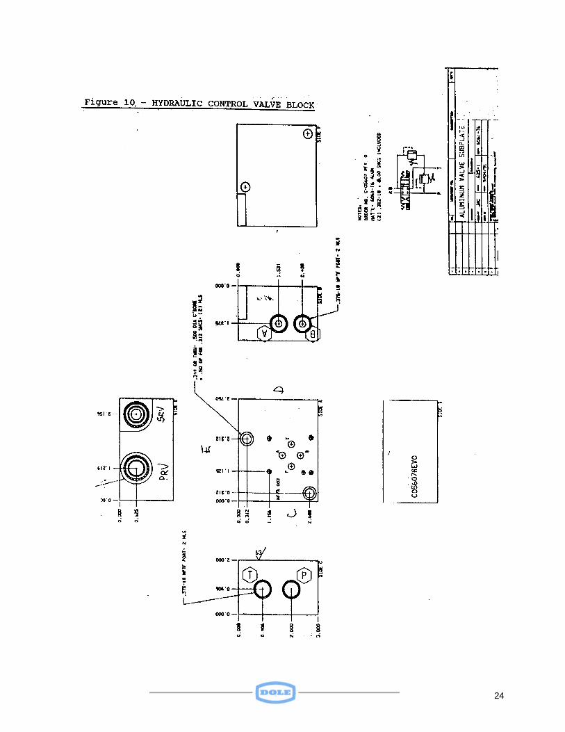
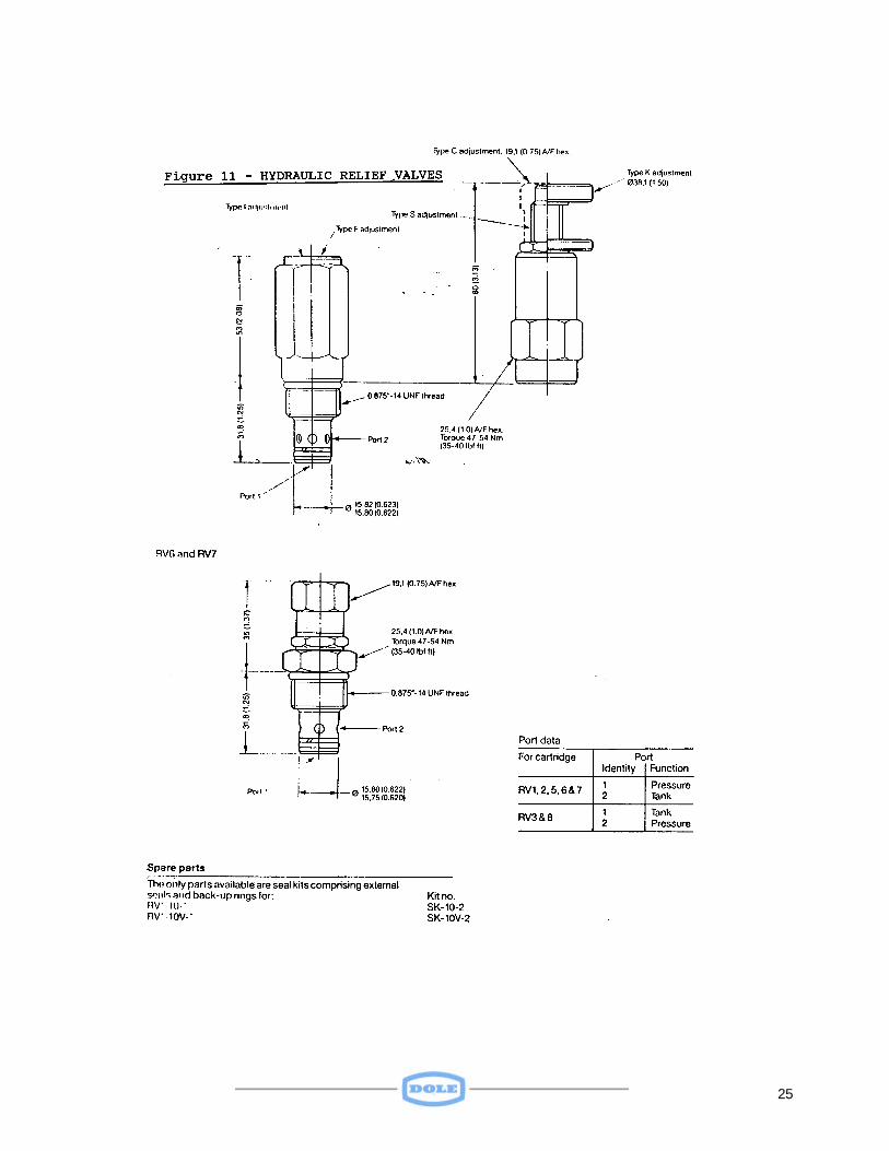
position. Placing the handle in the "Neutral" position will cause the plates to remain in whatever position they were in just before the handle was moved. The control valve is assembled to an aluminum block which serves to direct the hydraulic fluid from the pressure port ("P") on the block to either the "A" or to the "B" port, depending on the position of the valve handle. With the handle in the "up" position, the fluid flows out through the "A" port. From there it flows to the piston end of each actuator, after first passing through the flow diverter. Products tend to expand as they approach and pass through the freezing temperature. It is necessary, therefore to have some built-in provision to relieve this pressure before it reaches a level during freezing that could damage the system. Figure 10 depicts the control valve block. Figure 11 provides details on the relief valves. Should it be necessary to adjust a relief valve, the following procedure should be followed: See SPECIAL SUPPLEMENT for relief valve settings for the “10 psi” option freezer.
1) With the external source of hydraulic power on, and the control valve handle in the Neutral position, determine the line pressure. 2) Verify that the main relief valve in the external power source is set to at least 1250 psi and that the pressure to the control valve is above 1100 psi. 3) Adjust the freezer pressure relief valve (PRV) until the pressure to the valve drops to 1100 psi. (Turning the adjustment screw in clockwise will increase the pressure setting. Turning it counterclockwise will decrease the setting.) 4) With the external source of hydraulic power on, and the control valve handle in the Down position, adjust the "B" port relief valve (BRV) until the pressure drops to 1050 psi.
24
25
26
27
28
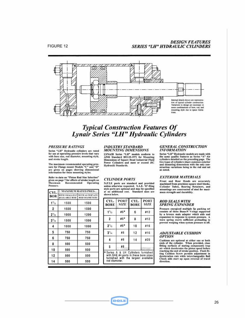
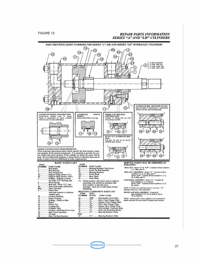
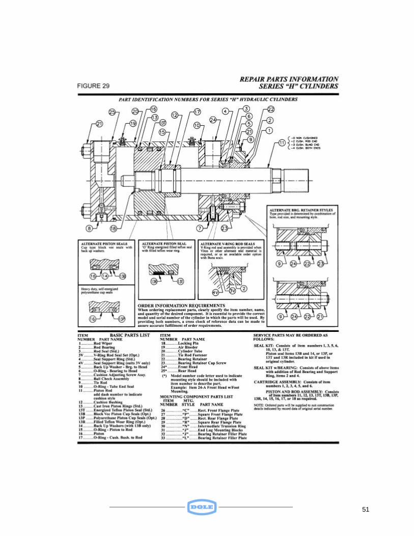
5.4.2 Hydraulic Actuator Maintenance See SPECIAL SUPPLEMENT for maintenance on actuators used on the “10 psi” option freezers. Figure 12 illustrates the typical construction features of the 3-1/4” cylinder used in the basic freezer configuration. It is designed to operate in a 1000 psi systems. Figure 13 provides Repair Parts information with respect to these cylinders. Suggested cylinder maintenance includes the replacement of seals subject to wear under normal operating conditions and the inspection of vital rod, bearing, and tube surfaces for abnormal wear or damage resulting from misalignment, particle contamination, or accidental abuse. When maintenance is to be performed, the cylinder should be removed to a clean work area. The unit should be disassembled as described below to replace desired seal items. Prior to reassembly, it is recommended that all cylinder surfaces and replacement parts be thoroughly cleaned and lubricated. The following procedure should be followed for rod seal replacement: (Refer to Figure 13)
1) Extend cylinder rod several inches and provide adequate support to avoid cocking the piston inside tube. 2) Inspect rod wrench flat area and remove any burrs to prevent damage to rod bearing upon its removal.
3) Remove fasteners and detach bearing retainer plate. 4) Remove bearing from rod by pulling with a slow twisting motion.
5) Remove v-ring rod seals from cylinder and cap using a hook tool or thin screwdriver. Use care not to scratch surfaces. Low-pressure air may be applied through front port to assist in seal removal. If used, rod should be fully retracted before such pressure is applied. 6) Remove rod wiper, clean, and inspect inner surface of the rod bearing. If bore finish is not uniform, measure for variations in size. If wear is apparent, replace rod bearing in addition to seal components. 7) After cleaning cylinder surfaces and lubricating replacement seals, install v-ring packing set into front head cavity. 8) Install new rod wiper, lubricate, and slide bearing onto rod using a slow twisting motion. 9) Reattach bearing retainer using appropriate fasteners. Torque requirement for proper reassembly is 34-foot lbs. Note: When tie rod nuts are removed to perform cylinder maintenance, they must be reassembled with proper torque to secure the assembly. To prevent twisting, attach vice grip pliers or a locking clamp to tie rod near end of unit where torque will be applied.
29
The following procedure should be followed for piston and tube end replacement: (Refer to Figure 13)
1) Pull cylinder rod to its fully extended position and provide adequate support to avoid cocking the piston inside tube. 2) Remove tie rod fasteners from end of unit most convenient for service purposes. 3) Remove rear end cap and separate front head from cylinder tube. Tubing must be supported to prevent cocking against piston during disassembly. 4) Slide piston out of cylinder tube to expose both seals. Remove packing by inserting blunt screwdriver under heel section and stretching seals over face of piston. 5) Clean piston and cylinder bore surfaces. Install new piston seals with cup form of each facing in opposite directions away from each other. 6) Remove tube end seal (either gasket or o-ring), clean head surface, and install replacement component. Lubricate prior to reassembly. 7) Insert piston into tube by depressing lip of seal with a blunt edge tool around circumference using care not to nick or scratch seal surface. 8) Align tube ends squarely with end cap pilots, slide together, and reattach tie rod fasteners. Use care not to shear o-ring if cylinder is Series "LH" model. 9) With piston rod in fully extended position, hand tighten tie rod fasteners. Torque gradually to recommended level by alternately tightening fasteners in a diagonal, corner-crossing pattern. 10) If cylinder size permits, push piston rod to rear of unit to check alignment. If binding occurs, loosen tie rods and repeat torque procedure. Cylinders with cushions should be assembled with the front cushion fully engaged. When assembled, proper alignment will allow full rotation of rod within the cushion at each end of cylinder. 11) After reassembly is complete, the cylinder should be pressure tested to inspect operating condition and checked for leakage before being placed back in service.
5.4.3 Hydraulic Flow Divider Maintenance The flow divider should prove to be a trouble-free item. However, if a problem should arise, such as jerky or uneven raising and lowering of the plates, it should be removed and replaced with Dole Part Number 28-129. 5.5 Lifting Bolt Maintenance Each Side Ram Freezer has three lengths of lifting bolts. Four bolts are used to secure the top plate to the Pressure Plate; four are used to control the maximum opening between the top plate and the next one down. The remainder of the lifting bolts is used to control openings between plates. The number of these bolts is equal to four times the number of stations less three. (For example, a 10-station freezer would require 4 x

30
(10-3) or 28 such bolts). Should a lifting bolt or its captive nut become defective, it should be replaced to prevent adverse structural stresses that could damage one or more plates.
31
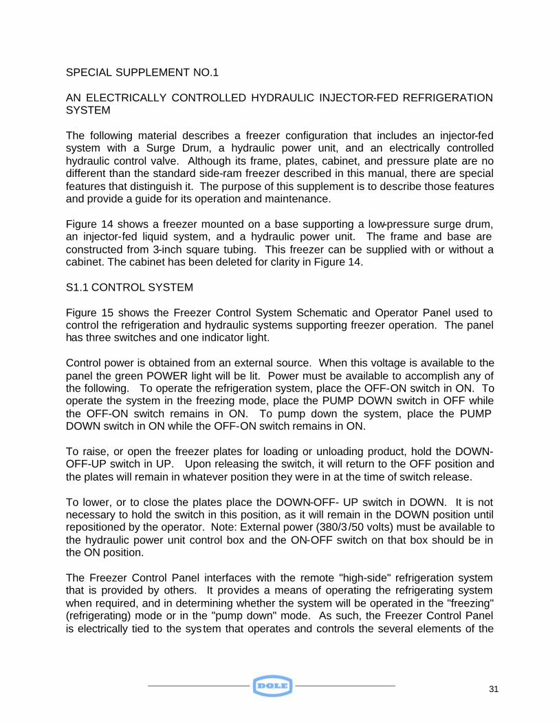
SPECIAL SUPPLEMENT NO.1 AN ELECTRICALLY CONTROLLED HYDRAULIC INJECTOR-FED REFRIGERATION SYSTEM The following material describes a freezer configuration that includes an injector-fed system with a Surge Drum, a hydraulic power unit, and an electrically controlled hydraulic control valve. Although its frame, plates, cabinet, and pressure plate are no different than the standard side-ram freezer described in this manual, there are special features that distinguish it. The purpose of this supplement is to describe those features and provide a guide for its operation and maintenance. Figure 14 shows a freezer mounted on a base supporting a low-pressure surge drum, an injector-fed liquid system, and a hydraulic power unit. The frame and base are constructed from 3-inch square tubing. This freezer can be supplied with or without a cabinet. The cabinet has been deleted for clarity in Figure 14. S1.1 CONTROL SYSTEM Figure 15 shows the Freezer Control System Schematic and Operator Panel used to control the refrigeration and hydraulic systems supporting freezer operation. The panel has three switches and one indicator light. Control power is obtained from an external source. When this voltage is available to the panel the green POWER light will be lit. Power must be available to accomplish any of the following. To operate the refrigeration system, place the OFF-ON switch in ON. To operate the system in the freezing mode, place the PUMP DOWN switch in OFF while the OFF-ON switch remains in ON. To pump down the system, place the PUMP DOWN switch in ON while the OFF-ON switch remains in ON. To raise, or open the freezer plates for loading or unloading product, hold the DOWN-OFF-UP switch in UP. Upon releasing the switch, it will return to the OFF position and the plates will remain in whatever position they were in at the time of switch release. To lower, or to close the plates place the DOWN-OFF- UP switch in DOWN. It is not necessary to hold the switch in this position, as it will remain in the DOWN position until repositioned by the operator. Note: External power (380/3 /50 volts) must be available to the hydraulic power unit control box and the ON-OFF switch on that box should be in the ON position. The Freezer Control Panel interfaces with the remote "high-side" refrigeration system that is provided by others. It provides a means of operating the refrigerating system when required, and in determining whether the system will be operated in the "freezing" (refrigerating) mode or in the "pump down" mode. As such, the Freezer Control Panel is electrically tied to the sys tem that operates and controls the several elements of the
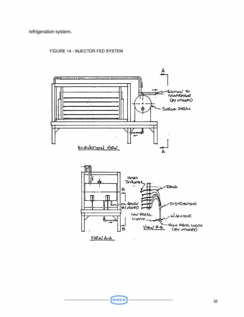
32
refrigeration system.
33
34
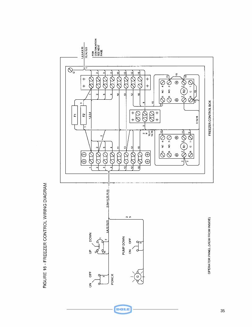
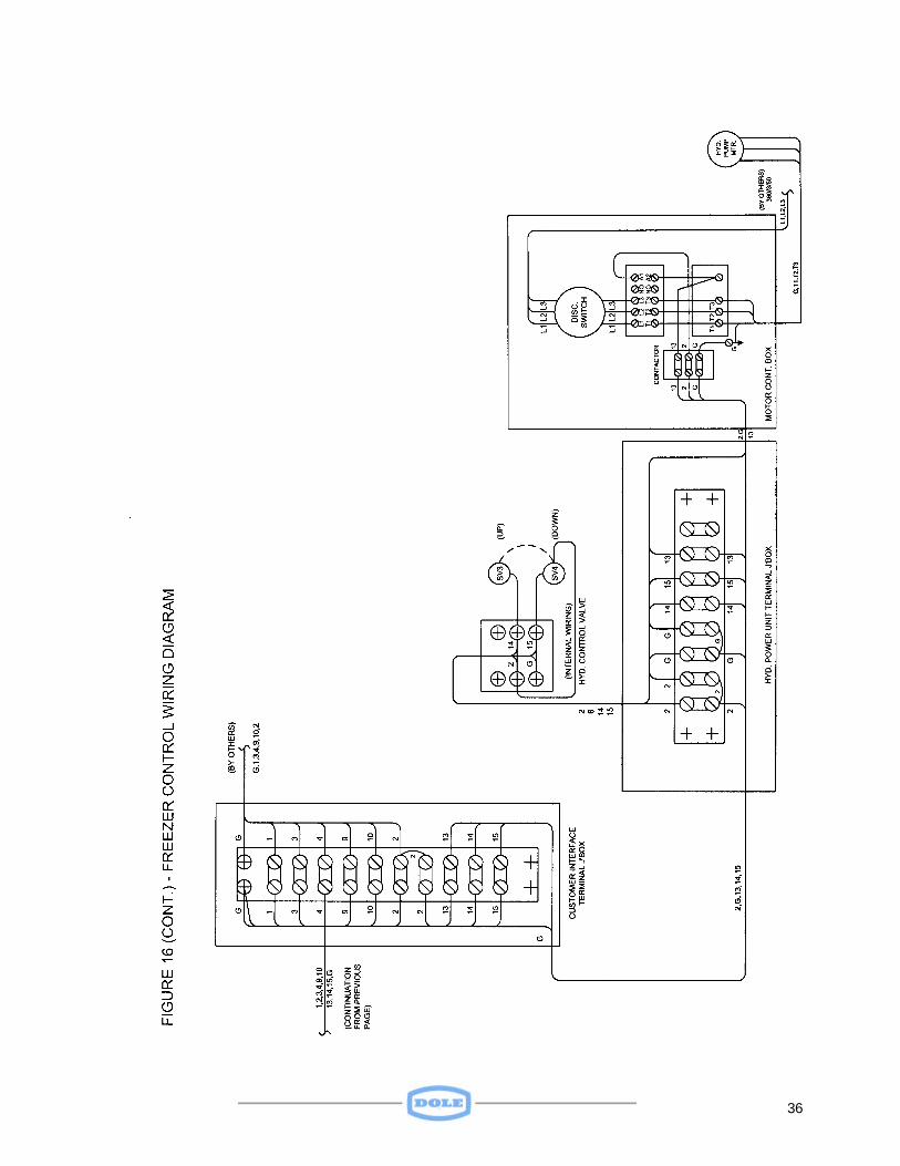
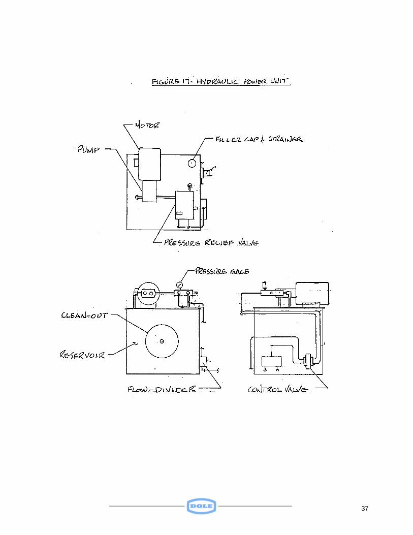
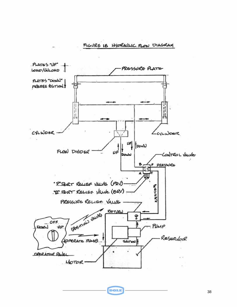
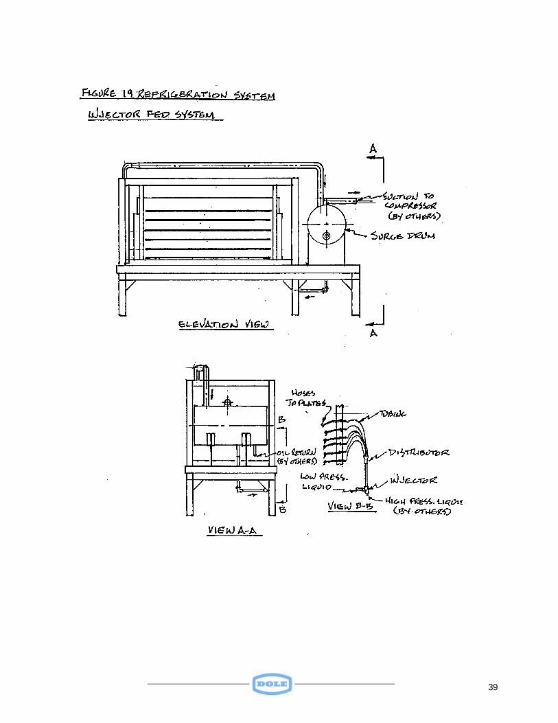
It should be pointed out that the refrigeration system cannot be operated, either in the refrigerating mode or in the pump down mode unless the OFF-ON switch on the Freezer Control Panel is in the ON position. Figure 16 shows the system schematic and wiring diagram for the Freezer Control Panel. S1.2 HYDRAULIC SYSTEM Whereas the standard side-ram freezer has a manual control valve and relies on an external source of hydraulic pressure, this unit has an electrically actuated hydraulic control valve, together with a self-contained hydraulic power unit. Like its standard counterpart, the system uses a flow divider to provide equal flow to each hydraulic cylinder when raising or lowering the plates. Figure 17 illustrates the hydraulic power unit furnished with this special unit. The hydraulic system flow diagram is presented on Figure 18. The use of the Freezer Control Panel to raise and lower freezer plates was discussed in the material IN S.1 CONTROL SYSTEM. The operation of the hydraulic system is independent of the refrigeration system in that the plates can be raised or lowered whether or not the refrigeration is in the freezing or in the pump-down mode. In like manner, the refrigeration system operates independently of the hydraulic system. Whereas, the refrigeration system requires the OFF-ON switch to be in ON to operate, the hydraulic system only requires that control POWER be available. S1.3 REFRIGERATION SYSTEM Even though this special unit contains more components of the refrigeration system than does the standard unit, it still must be considered as a "remote" freezer, i.e. it must rely on a remote high side. That portion of the refrigeration system provided with the freezer is shown in Figure 19. This injector-fed system is essentially a 2 to 1 overfeed system. As a result of feeding excess liquid to the evaporators (freezer plates), some liquid returns with the gas exiting the plates. The surge drum provides a means of separating the return liquid from the return gas and, thereby preventing the liquid refrigerant from finding its way back to the compressor and causing liquid flood back. In addition to preventing liquid flood back to the compressor, the surge drum provides a volume of very cold liquid refrigerant, which mixes with relatively warm condensed liquid from the receiver. This mixing of warm and cold liquid results in a sub cooled refrigerant being directed to the evaporators, with the higher efficiencies associated with such a cold fluid.
35
36
37
38
39
40
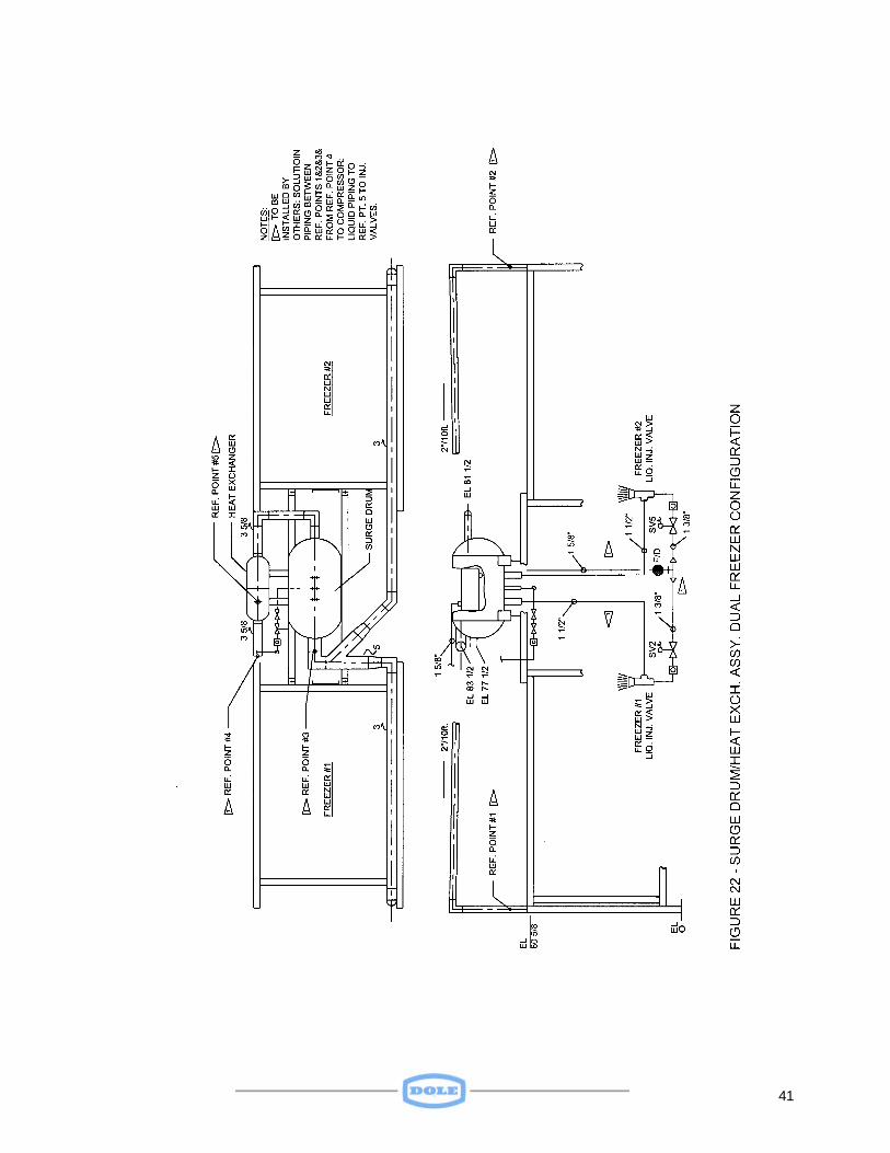
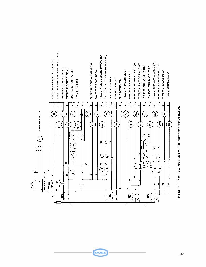
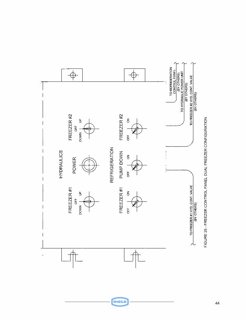
SPECIAL SUPPLEMENT NO. 2 A DUAL FREEZER ELECTRICALLY-CONTROLLED HYDRAULIC INJECTOR-FED REFRIGERATION SYSTEM The material in this Supplement describes a freezer configuration that includes two freezers, an injector-fed refrigeration system with a common Surge Drum, a Hydraulic Power Unit, and an electrically controlled Hydraulic Control Valve. Although the freezers’ frame, plates, and pressure plates are no different than the standard Side Ram version described elsewhere in this manual, there are special features that distinguish it. The purpose of this Supplement is to describe those features and provide a guide for its operation and maintenance. Figure 22 shows two freezers with a shared Surge Drum and Heat Exchanger and injector-fed liquid refrigerant system. The Surge Drum/Heat Exchanger Support structure is fabricated from 3-inch square tubing. The Freezer/Surge Drum/Heat Exchanger Assembly is housed in an insulated enclosure supplied by others. The freezer plates (evaporators) are fed through injectors, supplied with sub-cooled high-pressure liquid refrigerant and mixed with low-pressure liquid from the Surge Drum. This results in a 2 to 1 liquid recirculation rate. S2.1 CONTROL SYS TEM Figure 23 shows the electrical schematic for the dual freezer configuration. The system is comprised of two freezers, a remote “high-side” refrigeration system, and a remote hydraulic power unit. Two Control Panels provide the operator interfaces that enable the system as a whole to operate. One of these panels, the Freezer Control Panel, is depicted on Figure 24. This Figure also shows the Wiring Diagram and the interconnections between the several elements of the system. The Freezer Control Panel is shown on Figure 25. It is from this panel that the operator can control the refrigeration and hydraulic systems required to support freezer operation. The panel has 5 switches and 1 indicator light. Control power is obtained from an external source and transmitted through the Refrigeration Control Panel. If the power is available, the red POWER light will be lit. This light must be on, indicating that external power is available, for any of the systems to be operational. The operator can enable either or both freezers, Freezer No. 1 and/or Freezer No. 2, by placing one or both switches in the ON position. If a freezer is to be placed in the “freeze” mode, the REFRIGERATION PUMP DOWN switch must be placed in the OFF position. If the freezer is to be placed in the PUMP DOWN mode, the REFRIGERATION PUMP DOWN switch should be placed in the ON position.
41
42
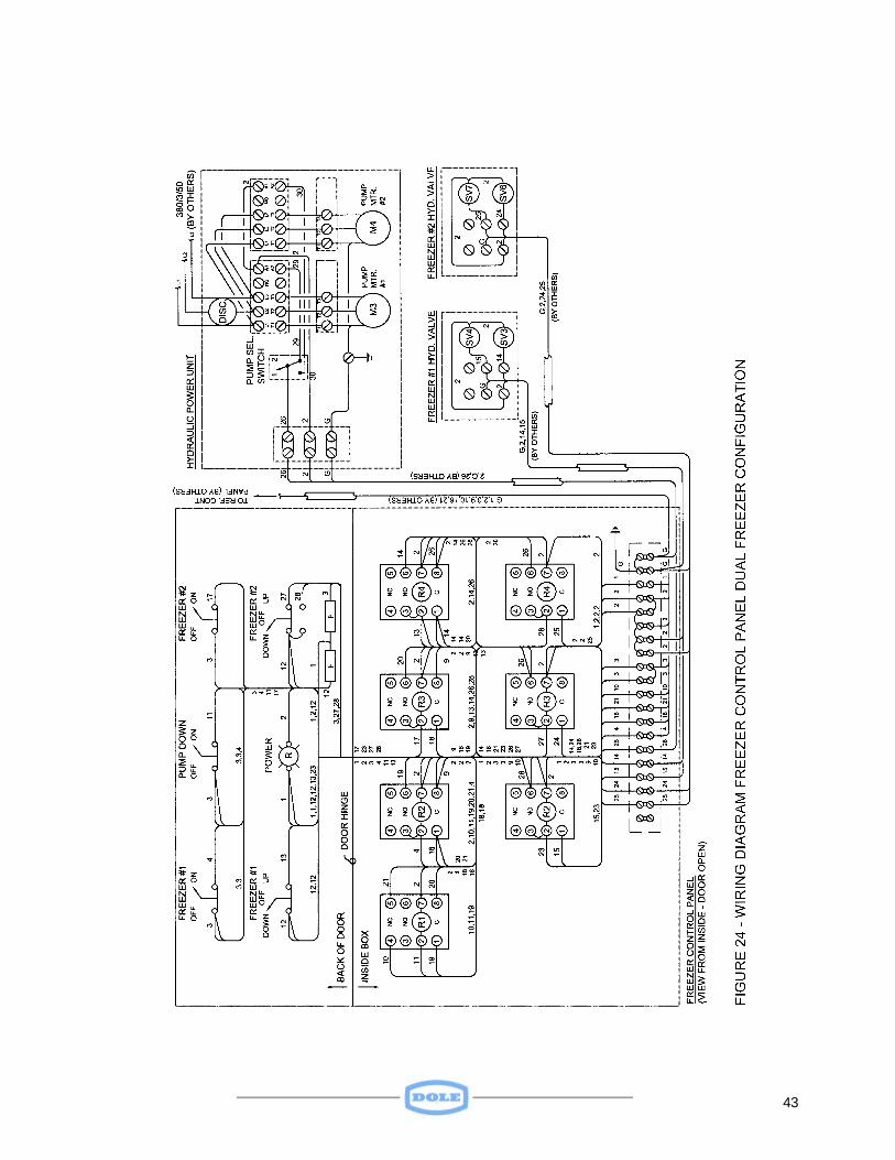
43
44
45
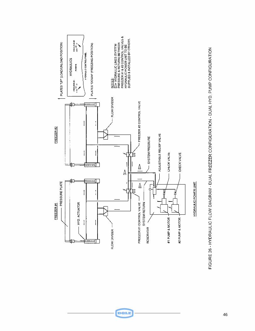
To raise or open freezer plates for loading and/or unloading operations the HYDRAULICS DOWN OFF UP switch must be placed in the UP position. Upon releasing the switch, the plates will remain in whatever position they were in at the time of switch release. To lower or close the plates the HYDRAULICS DOWN OFF UP switch must be placed in the DOWN position. It will not be necessary to hold the switch in this position, as it will remain in the DOWN position until repositioned by the operator. Note: External power must be available to the Hydraulic Power Unit and its Disconnect Switch closed. The Freezer Control Panel interfaces with the remote “high-side” refrigeration system through the Refrigeration System Control Panel provided by others. This provides a means of operating the refrigeration system when required to support freezing operations. It should be stressed that the refrigeration system cannot be operated unless at least one of the REFRIGERATION FREEZER NO. 1 or FREEZER NO. 2 switches is in the ON position. Whether the refrigeration system is operating in the PUMP DOWN or REFRIGERATE mode is dependent upon the position of the PUMP DOWN switch. S2.2 HYDRAULIC SYSTEM Whereas the standard Side Ram freezer has a manual hydraulic control valve, each freezer in this configuration has an electrically operated hydraulic control valve. Like its standard counterpart, these freezers use a flow divider to provide equal flow to each hydraulic cylinder when raising or lowering plates. Figure 26 presents the hydraulic flow diagram for the dual freezer configuration. The operation of the hydraulic system to raise or lower plates is independent of the refrigeration system. As such, it can be operated whether or not the refrigeration system is “on” or “off”, in the “refrigerating” or “pump down” mode. S2.3 REFRIGERATION SYSTEM Even though this dual freezer configuration contains more components of the total refrigeration system than does the standard unit, it still must be considered a “remote” unit, i.e. it must rely on a remote “high-side” refrigeration system. The freezer plates are the system’s evaporators, and the liquid injectors, surge drum and heat exchanger represent the freezers interface with the remote “high-side”. See Figure 22, which was previously discussed.
46
47
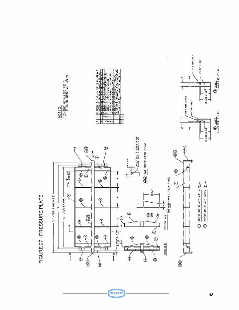
The Surge Drum, in addition to preventing liquid flood back to the compressors, provides a volume of very cold liquid refrigerant, which mixes with relatively warm condensed liquid from the receiver. This mix of relatively warm and very cold fluid results in a highly sub-cooled mixture being directed to the evaporators, with the resulting higher efficiency associated with such a cold fluid. SPECIAL SUPPLEMENT NO.3 A “10 PSI” OPTION FREEZER The material presented in this supplement describes the features that are peculiar to freezers built to provide 10 psi pressure on products during freezing. As such, these freezers constitute the “10 psi” option. Essentially, these freezers have a beefed-up frame and pressure plate and the hydraulic actuators are larger and rated at higher operating pressures than is the case for standard (3 to 5 psi product pressures) freezers. S3.1 FRAME Figure 2 presents a typical frame assembly. Whereas the standard freezer has a cylinder support fabricated from two steel angles, the cylinder support for the “10 psi” option is fabricated from two structural angles. It is this support that transmits the force exerted by the actuators on the Pressure Plate to Frame members. S3.2 PRESSURE PLATE The Pressure Plate described in paragraph 2.4 and shown in Figure 3 is sufficiently strong to provide a pressure of 5 psi on products in the standard freezer. However, a beefed-up version of this Pressure Plate is required to impose 10 psi on products during freezer. In addition to providing a uniform pressure on the product during freezing, the function of a Pressure Plate is to provide a means of lifting and lowering the nest of freezer plates and product during loading, unloading and freezing. See Figure 20 for details of the “10 psi” Pressure Plate. S3.3 HYDRAULIC SYSTEM The standard (3 to 5 psi product pressures) freezer operates at nominal 1000 psi. This pressure is adequate to provide, not only the appropriate product pressure, but is sufficient to lift the load made up of product, plates, refrigerant, and the Pressure Plate itself. Although 1000 psi is adequate to overcome lifting and lowering loads, it is insufficient to provide 10 psi over the product surface. Hence, the hydraulic actuators must be sized
48
49
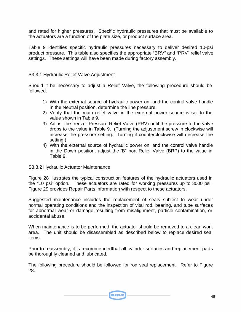
and rated for higher pressures. Specific hydraulic pressures that must be available to the actuators are a function of the plate size, or product surface area. Table 9 identifies specific hydraulic pressures necessary to deliver desired 10-psi product pressure. This table also specifies the appropriate “BRV” and “PRV” relief valve settings. These settings will have been made during factory assembly.
S3.3.1 Hydraulic Relief Valve Adjustment
Should it be necessary to adjust a Relief Valve, the following procedure should be followed:
1) With the external source of hydraulic power on, and the control valve handle
in the Neutral position, determine the line pressure. 2) Verify that the main relief valve in the external power source is set to the
value shown in Table 9. 3) Adjust the freezer Pressure Relief Valve (PRV) until the pressure to the valve
drops to the value in Table 9. (Turning the adjustment screw in clockwise will increase the pressure setting. Turning it counterclockwise will decrease the setting.)
4) With the external source of hydraulic power on, and the control valve handle in the Down position, adjust the “B” port Relief Valve (BRP) to the value in Table 9.
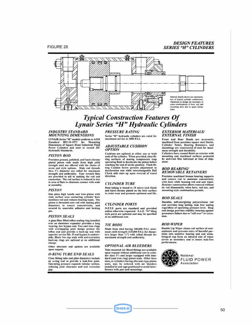
S3.3.2 Hydraulic Actuator Maintenance Figure 28 illustrates the typical construction features of the hydraulic actuators used in the “10 psi” option. These actuators are rated for working pressures up to 3000 psi. Figure 29 provides Repair Parts information with respect to these actuators. Suggested maintenance includes the replacement of seals subject to wear under normal operating conditions and the inspection of vital rod, bearing, and tube surfaces for abnormal wear or damage resulting from misalignment, particle contamination, or accidental abuse. When maintenance is to be performed, the actuator should be removed to a clean work area. The unit should be disassembled as described below to replace desired seal items. Prior to reassembly, it is recommendedthat all cylinder surfaces and replacement parts be thoroughly cleaned and lubricated. The following procedure should be followed for rod seal replacement. Refer to Figure 28.
50
51
52
1) Extend cylinder rod several inches and provide adequate support to avoid cocking the piston inside the tube.
2) Inspect rod wrench flat area and remove any burrs to prevent damage to rod bearing upon its removal.
3) Remove fasteners and detach bearing retainer plate. 4) Remove bearing from rod by pulling with a slow twisting motion. 5) Remove v-ring rod seals from cylinder and cap using a hook tool or thin
screwdriver. Use care not to scratch surfaces. Low-pressure air may be applied through front port to assist in seal removal. If used, rod should be fully retracted before such pressure is applied.
6) Remove rod wiper, clean, and inspect inner surface of the rod bearing. If finish of bore is not uniform, measure for variations in size. If wear is apparent, replace rod bearing in addition to seal components.
7) After cleaning cylinder surfaces and lubricating replacement seals, install v-ring packing set into front head cavity.
8) Install new rod wiper, lubricate and slide bearing onto rod using a slow twisting motion.
9) Reattach bearing retainer using appropriate fasteners. Torque requirement for proper reassembly is 34-foot pounds. Note: When tie rod nuts are removed to perform cylinder maintenance, they must be reassembled with proper torque to secure the assembly. To prevent twisting, attach vice grip pliers or a locking clamp to tie rod near end of unit where torque will be applied.

53
Appendix
54
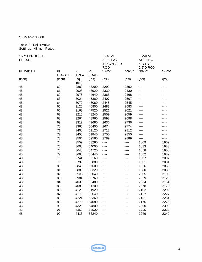
SIDMAN-105000 Table 1 - Relief Valve Settings - 48 inch Plates
15PSI PRODUCT PRESS
VALVE SETTING
VALVE SETTING
4"D CYL, 2"D ROD
5"D CYL, 2.5"D ROD
PL WIDTH PL LENGTH
PL AREA
PL LOAD
"BRV" "PRV" "BRV" "PRV"
(inch) (inch) (sq inch)
(lbs) (psi) (psi) (psi) (psi)
48 60 2880 43200 2292 2392 ---- ---- 48 61 2928 43920 2330 2430 ---- ---- 48 62 2976 44640 2368 2468 ---- ---- 48 63 3024 45360 2407 2507 ---- ---- 48 64 3072 46080 2445 2545 ---- ---- 48 65 3120 46800 2483 2583 ---- ---- 48 66 3168 47520 2521 2621 ---- ---- 48 67 3216 48240 2559 2659 ---- ---- 48 68 3264 48960 2598 2698 ---- ---- 48 69 3312 49680 2636 2736 ---- ---- 48 70 3360 50400 2674 2774 ---- ---- 48 71 3408 51120 2712 2812 ---- ---- 48 72 3456 51840 2750 2850 ---- ---- 48 73 3504 52560 2789 2889 ---- ---- 48 74 3552 53280 ---- ---- 1809 1909 48 75 3600 54000 ---- ---- 1833 1933 48 76 3648 54720 ---- ---- 1858 1958 48 77 3696 55440 ---- ---- 1882 1982 48 78 3744 56160 ---- ---- 1907 2007 48 79 3792 56880 ---- ---- 1931 2031 48 80 3840 57600 ---- ---- 1956 2056 48 81 3888 58320 ---- ---- 1980 2080 48 82 3936 59040 ---- ---- 2005 2105 48 83 3984 59760 ---- ---- 2029 2129 48 84 4032 60480 ---- ---- 2054 2154 48 85 4080 61200 ---- ---- 2078 2178 48 86 4128 61920 ---- ---- 2102 2202 48 87 4176 62640 ---- ---- 2127 2227 48 88 4224 63360 ---- ---- 2151 2251 48 89 4272 64080 ---- ---- 2176 2276 48 90 4320 64800 ---- ---- 2200 2300 48 91 4368 65520 ---- ---- 2225 2325 48 92 4416 66240 ---- ---- 2249 2349
55
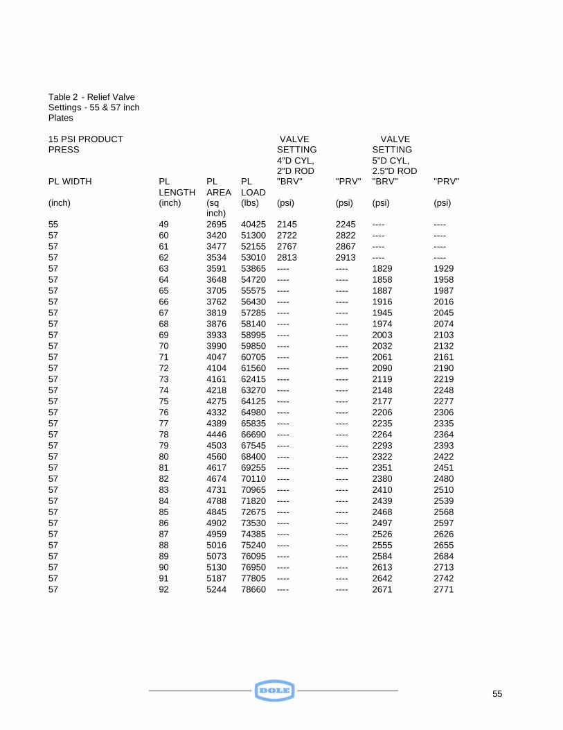
Table 2 - Relief Valve Settings - 55 & 57 inch Plates
15 PSI PRODUCT PRESS
VALVE SETTING
VALVE SETTING
4"D CYL, 2"D ROD
5"D CYL, 2.5"D ROD
PL WIDTH PL LENGTH
PL AREA
PL LOAD
"BRV" "PRV" "BRV" "PRV"
(inch) (inch) (sq inch)
(lbs) (psi) (psi) (psi) (psi)
55 49 2695 40425 2145 2245 ---- ---- 57 60 3420 51300 2722 2822 ---- ---- 57 61 3477 52155 2767 2867 ---- ---- 57 62 3534 53010 2813 2913 ---- ---- 57 63 3591 53865 ---- ---- 1829 1929 57 64 3648 54720 ---- ---- 1858 1958 57 65 3705 55575 ---- ---- 1887 1987 57 66 3762 56430 ---- ---- 1916 2016 57 67 3819 57285 ---- ---- 1945 2045 57 68 3876 58140 ---- ---- 1974 2074 57 69 3933 58995 ---- ---- 2003 2103 57 70 3990 59850 ---- ---- 2032 2132 57 71 4047 60705 ---- ---- 2061 2161 57 72 4104 61560 ---- ---- 2090 2190 57 73 4161 62415 ---- ---- 2119 2219 57 74 4218 63270 ---- ---- 2148 2248 57 75 4275 64125 ---- ---- 2177 2277 57 76 4332 64980 ---- ---- 2206 2306 57 77 4389 65835 ---- ---- 2235 2335 57 78 4446 66690 ---- ---- 2264 2364 57 79 4503 67545 ---- ---- 2293 2393 57 80 4560 68400 ---- ---- 2322 2422 57 81 4617 69255 ---- ---- 2351 2451 57 82 4674 70110 ---- ---- 2380 2480 57 83 4731 70965 ---- ---- 2410 2510 57 84 4788 71820 ---- ---- 2439 2539 57 85 4845 72675 ---- ---- 2468 2568 57 86 4902 73530 ---- ---- 2497 2597 57 87 4959 74385 ---- ---- 2526 2626 57 88 5016 75240 ---- ---- 2555 2655 57 89 5073 76095 ---- ---- 2584 2684 57 90 5130 76950 ---- ---- 2613 2713 57 91 5187 77805 ---- ---- 2642 2742 57 92 5244 78660 ---- ---- 2671 2771
56
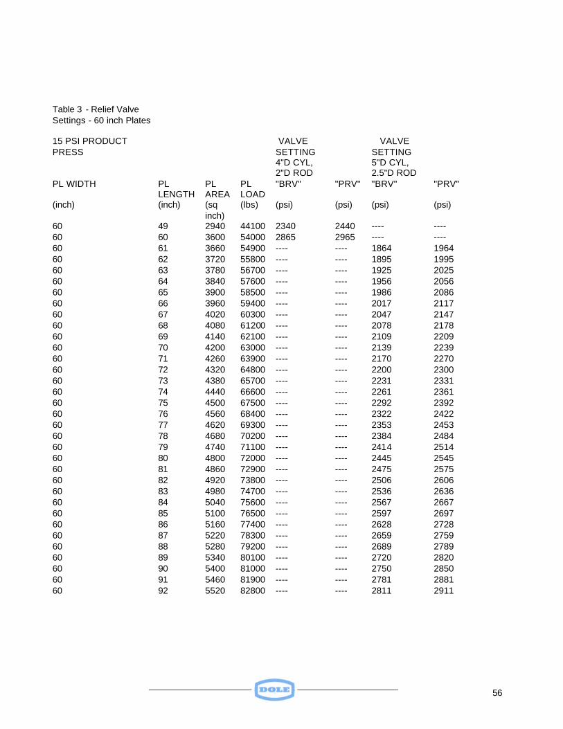
Table 3 - Relief Valve Settings - 60 inch Plates
15 PSI PRODUCT PRESS
VALVE SETTING
VALVE SETTING
4"D CYL, 2"D ROD
5"D CYL, 2.5"D ROD
PL WIDTH PL LENGTH
PL AREA
PL LOAD
"BRV" "PRV" "BRV" "PRV"
(inch) (inch) (sq inch)
(lbs) (psi) (psi) (psi) (psi)
60 49 2940 44100 2340 2440 ---- ---- 60 60 3600 54000 2865 2965 ---- ---- 60 61 3660 54900 ---- ---- 1864 1964 60 62 3720 55800 ---- ---- 1895 1995 60 63 3780 56700 ---- ---- 1925 2025 60 64 3840 57600 ---- ---- 1956 2056 60 65 3900 58500 ---- ---- 1986 2086 60 66 3960 59400 ---- ---- 2017 2117 60 67 4020 60300 ---- ---- 2047 2147 60 68 4080 61200 ---- ---- 2078 2178 60 69 4140 62100 ---- ---- 2109 2209 60 70 4200 63000 ---- ---- 2139 2239 60 71 4260 63900 ---- ---- 2170 2270 60 72 4320 64800 ---- ---- 2200 2300 60 73 4380 65700 ---- ---- 2231 2331 60 74 4440 66600 ---- ---- 2261 2361 60 75 4500 67500 ---- ---- 2292 2392 60 76 4560 68400 ---- ---- 2322 2422 60 77 4620 69300 ---- ---- 2353 2453 60 78 4680 70200 ---- ---- 2384 2484 60 79 4740 71100 ---- ---- 2414 2514 60 80 4800 72000 ---- ---- 2445 2545 60 81 4860 72900 ---- ---- 2475 2575 60 82 4920 73800 ---- ---- 2506 2606 60 83 4980 74700 ---- ---- 2536 2636 60 84 5040 75600 ---- ---- 2567 2667 60 85 5100 76500 ---- ---- 2597 2697 60 86 5160 77400 ---- ---- 2628 2728 60 87 5220 78300 ---- ---- 2659 2759 60 88 5280 79200 ---- ---- 2689 2789 60 89 5340 80100 ---- ---- 2720 2820 60 90 5400 81000 ---- ---- 2750 2850 60 91 5460 81900 ---- ---- 2781 2881 60 92 5520 82800 ---- ---- 2811 2911
57
58
59
60
61
62
63
Cooling Load vs Plate Size & Product Thickness
PLATE PLATE PRODUCT PRODUCT PRODUCT PRODUCT COOLING FREEZING COOLING DESIGN TONS WIDTH LENGTH THICKNESS DENSITY VOLUME WEIGHT LOAD TIME RATE LOAD REFRIG. (inch) (inch) (inch) (lbs/cf) (cf/Sta.) (lbs/Sta.) (BTU/Sta.) (Hours) (BTUH/Sta
.) (BTUH/Sta)
(TR/Sta.)
= = = = = = = = = = = 48 60 1.00 50 1.67 83 12167 1.00 12167 15208 1.27 48 60 1.50 50 2.50 125 18250 1.75 10429 13036 1.09 48 60 2.00 50 3.33 167 24333 2.50 9733 12167 1.01 48 60 2.50 50 4.17 208 30417 3.50 8690 10863 0.91 48 60 3.00 50 5.00 250 36500 4.50 8111 10139 0.84 48 65 1.00 50 1.81 90 13181 1.00 13181 16476 1.37 48 65 1.50 50 2.71 135 19771 1.75 11298 14122 1.18 48 65 2.00 50 3.61 181 26361 2.50 10544 13181 1.10 48 65 2.50 50 4.51 226 32951 3.50 9415 11768 0.98 48 65 3.00 50 5.42 271 39542 4.50 8787 10984 0.92 48 70 1.00 50 1.94 97 14194 1.00 14194 17743 1.48 48 70 1.50 50 2.92 146 21292 1.75 12167 15208 1.27 48 70 2.00 50 3.89 194 28389 2.50 11356 14194 1.18 48 70 2.50 50 4.86 243 35486 3.50 10139 12674 1.06 48 70 3.00 50 5.83 292 42583 4.50 9463 11829 0.99 48 75 1.00 50 2.08 104 15208 1.00 15208 19010 1.58 48 75 1.50 50 3.13 156 22813 1.75 13036 16295 1.36 48 75 2.00 50 4.17 208 30417 2.50 12167 15208 1.27 48 75 2.50 50 5.21 260 38021 3.50 10863 13579 1.13 48 75 3.00 50 6.25 313 45625 4.50 10139 12674 1.06 48 80 1.00 50 2.22 111 16222 1.00 16222 20278 1.69 48 80 1.50 50 3.33 167 24333 1.75 13905 17381 1.45 48 80 2.00 50 4.44 222 32444 2.50 12978 16222 1.35 48 80 2.50 50 5.56 278 40556 3.50 11587 14484 1.21 48 80 3.00 50 6.67 333 48667 4.50 10815 13519 1.13 48 85 1.00 50 2.36 118 17236 1.00 17236 21545 1.80 48 85 1.50 50 3.54 177 25854 1.75 14774 18467 1.54 48 85 2.00 50 4.72 236 34472 2.50 13789 17236 1.44 48 85 2.50 50 5.90 295 43090 3.50 12312 15389 1.28 48 85 3.00 50 7.08 354 51708 4.50 11491 14363 1.20 48 90 1.00 50 2.50 125 18250 1.00 18250 22813 1.90 48 90 1.50 50 3.75 188 27375 1.75 15643 19554 1.63 48 90 2.00 50 5.00 250 36500 2.50 14600 18250 1.52 48 90 2.50 50 6.25 313 45625 3.50 13036 16295 1.36 48 90 3.00 50 7.50 375 54750 4.50 12167 15208 1.27 55 49 1.00 50 1.56 78 11385 1.00 11385 14231 1.19 55 49 1.50 50 2.34 117 17078 1.75 9759 12198 1.02 55 49 2.00 50 3.12 156 22770 2.50 9108 11385 0.95 55 49 2.50 50 3.90 195 28463 3.50 8132 10165 0.85 55 49 3.00 50 4.68 234 34155 4.50 7590 9488 0.79 57 49 1.00 50 1.62 81 11799 1.00 11799 14749 1.23 57 49 1.50 50 2.42 121 17699 1.75 10114 12642 1.05 57 49 2.00 50 3.23 162 23598 2.50 9439 11799 0.98 57 49 2.50 50 4.04 202 29498 3.50 8428 10535 0.88 57 49 3.00 50 4.85 242 35397 4.50 7866 9833 0.82 57 60 1.00 50 1.98 99 14448 1.00 14448 18060 1.50
64
PLATE PLATE PRODUCT PRODUCT PRODUCT PRODUCT COOLING FREEZING COOLING DESIGN TONS WIDTH LENGTH THICKNESS DENSITY VOLUME WEIGHT LOAD TIME RATE LOAD REFRIG. (inch) (inch) (inch) (lbs/cf) (cf/Sta.) (lbs/Sta.) (BTU/Sta.) (hours) (BTUH/Sta
.) (BTUH/Sta.)
(TR/Sta.)
57 60 1.50 50 2.97 148 21672 1.75 12384 15480 1.29 57 60 2.00 50 3.96 198 28896 2.50 11558 14448 1.20 57 60 2.50 50 4.95 247 36120 3.50 10320 12900 1.07 57 60 3.00 50 5.94 297 43344 4.50 9632 12040 1.00 57 65 1.00 50 2.14 107 15652 1.00 15652 19565 1.63 57 65 1.50 50 3.22 161 23478 1.75 13416 16770 1.40 57 65 2.00 50 4.29 214 31304 2.50 12522 15652 1.30 57 65 2.50 50 5.36 268 39130 3.50 11180 13975 1.16 57 65 3.00 50 6.43 322 46956 4.50 10435 13043 1.09 57 70 1.00 50 2.31 115 16856 1.00 16856 21070 1.76 57 70 1.50 50 3.46 173 25284 1.75 14448 18060 1.50 57 70 2.00 50 4.62 231 33712 2.50 13485 16856 1.40 57 70 2.50 50 5.77 289 42140 3.50 12040 15050 1.25 57 70 3.00 50 6.93 346 50568 4.50 11237 14047 1.17 57 75 1.00 50 2.47 124 18060 1.00 18060 22575 1.88 57 75 1.50 50 3.71 186 27090 1.75 15480 19350 1.61 57 75 2.00 50 4.95 247 36120 2.50 14448 18060 1.50 57 75 2.50 50 6.18 309 45150 3.50 12900 16125 1.34 57 75 3.00 50 7.42 371 54180 4.50 12040 15050 1.25 57 80 1.00 50 2.64 132 19264 1.00 19264 24080 2.01 57 80 1.50 50 3.96 198 28896 1.75 16512 20640 1.72 57 80 2.00 50 5.28 264 38528 2.50 15411 19264 1.61 57 80 2.50 50 6.60 330 48160 3.50 13760 17200 1.43 57 80 3.00 50 7.92 396 57792 4.50 12843 16053 1.34 57 85 1.00 50 2.80 140 20468 1.00 20468 25585 2.13 57 85 1.50 50 4.21 210 30702 1.75 17544 21930 1.83 57 85 2.00 50 5.61 280 40936 2.50 16374 20468 1.71 57 85 2.50 50 7.01 350 51170 3.50 14620 18275 1.52 57 85 3.00 50 8.41 421 61404 4.50 13645 17057 1.42 57 90 1.00 50 2.97 148 21672 1.00 21672 27090 2.26 57 90 1.50 50 4.45 223 32508 1.75 18576 23220 1.93 57 90 2.00 50 5.94 297 43344 2.50 17338 21672 1.81 57 90 2.50 50 7.42 371 54180 3.50 15480 19350 1.61 57 90 3.00 50 8.91 445 65016 4.50 14448 18060 1.50 60 60 1.00 50 2.08 104 15208 1.00 15208 19010 1.58 60 60 1.50 50 3.13 156 22813 1.75 13036 16295 1.36 60 60 2.00 50 4.17 208 30417 2.50 12167 15208 1.27 60 60 2.50 50 5.21 260 38021 3.50 10863 13579 1.13 60 60 3.00 50 6.25 313 45625 4.50 10139 12674 1.06 60 65 1.00 50 2.26 113 16476 1.00 16476 20595 1.72 60 65 1.50 50 3.39 169 24714 1.75 14122 17653 1.47 60 65 2.00 50 4.51 226 32951 2.50 13181 16476 1.37 60 65 2.50 50 5.64 282 41189 3.50 11768 14710 1.23 60 65 3.00 50 6.77 339 49427 4.50 10984 13730 1.14 60 70 1.00 50 2.43 122 17743 1.00 17743 22179 1.85 60 70 1.50 50 3.65 182 26615 1.75 15208 19010 1.58 60 70 2.00 50 4.86 243 35486 2.50 14194 17743 1.48 60 70 2.50 50 6.08 304 44358 3.50 12674 15842 1.32 60 70 3.00 50 7.29 365 53229 4.50 11829 14786 1.23
65
PLATE PLATE PRODUCT PRODUCT PRODUCT PRODUCT COOLING FREEZING COOLING DESIGN TONS WIDTH LENGTH THICKNESS DENSITY VOLUME WEIGHT LOAD TIME RATE LOAD REFRIG (inch) (inch) (inch) (lbs/cf) (cf/Sta.) (lbs/Sta.) (BTU/Sta.) (hours) (BTUH/Sta
.) (BTUH/Sta.)
(TR/Sta.)
60 75 1.00 50 2.60 130 19010 1.00 19010 23763 1.98 60 75 1.50 50 3.91 195 28516 1.75 16295 20368 1.70 60 75 2.00 50 5.21 260 38021 2.50 15208 19010 1.58 60 75 2.50 50 6.51 326 47526 3.50 13579 16974 1.41 60 75 3.00 50 7.81 391 57031 4.50 12674 15842 1.32 60 80 1.00 50 2.78 139 20278 1.00 20278 25347 2.11 60 80 1.50 50 4.17 208 30417 1.75 17381 21726 1.81 60 80 2.00 50 5.56 278 40556 2.50 16222 20278 1.69 60 80 2.50 50 6.94 347 50694 3.50 14484 18105 1.51 60 80 3.00 50 8.33 417 60833 4.50 13519 16898 1.41 60 85 1.00 50 2.95 148 21545 1.00 21545 26931 2.24 60 85 1.50 50 4.43 221 32318 1.75 18467 23084 1.92 60 85 2.00 50 5.90 295 43090 2.50 17236 21545 1.80 60 85 2.50 50 7.38 369 53863 3.50 15389 19237 1.60 60 85 3.00 50 8.85 443 64635 4.50 14363 17954 1.50 60 90 1.00 50 3.13 156 22813 1.00 22813 28516 2.38 60 90 1.50 50 4.69 234 34219 1.75 19554 24442 2.04 60 90 2.00 50 6.25 313 45625 2.50 18250 22813 1.90 60 90 2.50 50 7.81 391 57031 3.50 16295 20368 1.70 60 90 3.00 50 9.38 469 68438 4.50 15208 19010 1.58 60 46 2.50 50 3.99 200 29149 3.50 8328 10410 0.87
66
Sidman – SideRam Freezer – Parts List
Part No. Description 28-129 Flow Divider,inlet 1/2"FPT, outlet 3/8"FPT Hydraulic Cylinder (differs with no. of stations and opening width) 28-218 Manual Valve, Pressure Differential 28-222 Electric Valve, Control, solenoid operated 240v 07-055 Rod Clevis w/ pin 07-055-1 Pivot Pin & Retain ring for RC100 07-055A Pivot Pin w/ring 26-027 Liquid Hoses (contact Dole Engineering) 26-028 Suction Hoses (contact Dole Engineering) Hardware for Cabinet
67
Limited Warranty Dole Refrigerating Company
1420 Higgs Road Lewisburg, TN 37091
Terms of Limited Warranty- Dole Plate Freezers
Limited Warranty
Dole warrants to the original purchaser-user that the new product is free from defects of manufacture, material and/or workmanship at the time of shipment from Dole . This warranty does not extend to future performance. Any claims against Dole must be initiated within the time periods stipulated in paragraphs following, and not later. Dole obligation, and purchaser-user’s exclusive remedy, under this warranty is limited to furnishing a new or rebuilt part in exchange for a part which, is both defective and in-warranty, within 12 months from the date of startup, or 14 months from date of shipment from Dole, whichever is earlier. This warranty is given to the original purchaser-user in lieu of all other warranties and shall not be assignable.
Limitations And Exclusions This warranty shall not apply to: a. Spoilage or loss of perishables for any reason b. Refrigerant c. Charges for installation of any part or parts furnished under this warranty
d. Transportation costs of the new or rebuilt part to the installation site, or of the defective part from the installation site to Dole. e. Normal service and maintenance costs.
Dole shall not be liable for defects or damage, which result from or are caused by: a. Improper installation, wiring, electrical current characteristics, or maintenance.
b. Accident, misuse or abuse, fire, flood, alteration and/or misapplication of the product. c. Default or delay in performance caused by war, government restrictions, strikes, material shortages and contingency beyond the control of Dole, or acts of God.
Anything in the warranty notwithstanding. ALL IMPLIED WARRANTIES OF FITNESS FOR PARTICULAR PURPOSE AND MERCHANTABILITY ARE EXCLUDED.
MANUFACTURER EXPRESSLY DISCLAIMS AND EXCLUDES ANY LIABILITY FOR CONSEQUENTIAL OR INCIDENTAL DAMAGE OR PERSONAL INJURY FOR BREACH OF ANY EXPRESS OR IMPLIED WARRANTY.


![7 Referências - DBD PUC RIO · [Sidman & Tailby, 1982] SIDMAN, M.; TAILBY, W. Conditional discrimination vs. Matching-to- sample: An expansion of the testing paradigma. Journal of](https://img.pdfslide.net/doc/110x75/5ade0a757f8b9a9a768dbbf0/7-referncias-dbd-puc-sidman-tailby-1982-sidman-m-tailby-w-conditional-discrimination.jpg)