Embed Size (px)
Citation preview

iLOGO! ManualA5E00046684 01
Welcome to LOGO!Dear customer,
Thank you for purchasing LOGO!, and congratulations on yourdecision. In LOGO! you have acquired a logic module that meetsthe stringent quality requirements of ISO 9001.
LOGO! is universal in application. Its comprehensive functionalityand great ease of use make it a highly cost-efficient solution forvirtually any application.
LOGO! documentationThis LOGO! manual tells you how to install, program and useLOGO!.
You can find information on wiring in the LOGO! manual as well asin the LOGO! product information that is supplied with each de-vice. You can get further information on programming LOGO! viathe PC in the LOGO!Soft and LOGO!Soft Comfort online help sy-stem. LOGO!Soft and LOGO!Soft Comfort are programming soft-ware for PCs. They run under WINDOWSR and will help you getto know LOGO! and to write, test, print out and archive programsindependently of LOGO!.
Guide to the manualWe have subdivided this manual into 8 chapters:S Getting to know LOGO!S Installing and wiring LOGO!S Programming LOGO!S Parameterizing LOGO!S LOGO!’s program modulesS LOGO! softwareS ApplicationsS Appendices (technical specifications, determination of memory
requirements, LOGO! without display, AS interface-specificinformation, order numbers)
Additional supportYou can find answers to your LOGO! questions quickly and easilyon the Internet at http://www.ad.siemens.de/logo .

LOGO! ManualA5E00046684 01
ii
Safety guidelinesThis manual contains notices which you should observe to ensureyour own personal safety, as well as to protect the product andconnected equipment. These notices are highlighted in the ma-nual by a warning triangle and are marked as follows according tothe level of danger:
!Danger
Indicates that death, severe personal injury or substantial prop-erty damage will result if proper precautions are not taken.
!Warning
Indicates that death, severe personal injury or substantial prop-erty damage can result if proper precautions are not taken.
!Caution
Indicates that minor personal injury or property damage canresult if proper precautions are not taken.
NoteDraws your intention to particularly important information onthe product, handling the product, or to a particular part of thedocumentation.
!Warning
Only qualified personnel should be allowed to install andwork on this equipment. Qualified personnel are defined aspersons who are authorized to commission, to ground and totag circuits, equipment and systems in accordance with estab-lished safety practices and standards.
!Warning
This device may only be used for the applications described inthe catalog and the technical description, and only with non-Siemens devices or components if they have been approvedor recommended by Siemens.This product can only function correctly and safely if it is trans-ported, stored, set up, and installed correctly, and operatedand maintained as recommended.
Welcome to LOGO!

iiiLOGO! ManualA5E00046684 01
Copyright E Siemens AG 1996 All rights reservedThe reproduction, transmission or use of this document or its contents is not permittedwithout express written authority. Offenders will be liable for damages. All rights reserved, inparticular in the event of a patent being granted or the registration of a utility model or design.Disclaimer of liabilityWe have checked the contents of this manual for agreement with the hardware and soft-ware described. Since deviations cannot be precluded entirely, we cannot guarantee fullagreement. However, the data in this manual is reviewed regularly and any necessarycorrections included in subsequent editions. Suggestions for improvement are welcomed.
Welcome to LOGO!
LOGO! ManualA5E00046684 01
iv
Contents
1 Getting to know LOGO! 1. . . . . . . . . . .
2 Installing and wiring LOGO! 7. . . . . . . 2.1 Installing/deinstalling LOGO! 8. . . . . . . . . . . . . . . . . . .
2.2 Wiring LOGO! 9. . . . . . . . . . . . . . . . . . . . . . . . . . . . . . . . . 2.2.1 Connecting the power supply 9. . . . . . . . . . . . . . . . . . . 2.2.2 Connecting LOGO!’s inputs 11. . . . . . . . . . . . . . . . . . . . 2.2.3 Connecting outputs 15. . . . . . . . . . . . . . . . . . . . . . . . . . . . 2.2.4 Connecting the ASi bus (LOGO! ...B11 only) 17. . . . . . 2.2.5 LOGO!...B11 on the ASi bus 18. . . . . . . . . . . . . . . . . . . .
2.3 Switching LOGO! on/resumption of power 19. . . . . .
3 Programming LOGO! 22. . . . . . . . . . . . . 3.1 Connectors 24. . . . . . . . . . . . . . . . . . . . . . . . . . . . . . . . . . .
3.2 Blocks and block numbers 26. . . . . . . . . . . . . . . . . . . . .
3.3 From circuit diagram to LOGO! 29. . . . . . . . . . . . . . . . .
3.4 The 4 golden rules for working with LOGO! 32. . . . .
3.5 Overview of LOGO!’s menus 34. . . . . . . . . . . . . . . . . . .
3.6 Entering and starting a program 35. . . . . . . . . . . . . . . . 3.6.1 Switching to programming mode 35. . . . . . . . . . . . . . . . 3.6.2 First program 36. . . . . . . . . . . . . . . . . . . . . . . . . . . . . . . . . 3.6.3 Entering the program 38. . . . . . . . . . . . . . . . . . . . . . . . . . 3.6.4 Second program 45. . . . . . . . . . . . . . . . . . . . . . . . . . . . . . 3.6.5 Deleting a block 51. . . . . . . . . . . . . . . . . . . . . . . . . . . . . . . 3.6.6 Deleting a number of interconnected blocks 52. . . . . . 3.6.7 Correcting typing errors 53. . . . . . . . . . . . . . . . . . . . . . . . 3.6.8 ”?” on the display 53. . . . . . . . . . . . . . . . . . . . . . . . . . . . . 3.6.9 Deletinga program 54. . . . . . . . . . . . . . . . . . . . . . . . . . . .
3.7 Functions 55. . . . . . . . . . . . . . . . . . . . . . . . . . . . . . . . . . . . .
3.8 Constants and connectors – (Co) 56. . . . . . . . . . . . . . .
vLOGO! ManualA5E00046684 01
3.9 Basic functions – BF 58. . . . . . . . . . . . . . . . . . . . . . . . . . . 3.9.1 AND 59. . . . . . . . . . . . . . . . . . . . . . . . . . . . . . . . . . . . . . . . 3.9.2 OR 59. . . . . . . . . . . . . . . . . . . . . . . . . . . . . . . . . . . . . . . . . . 3.9.3 NOT (negation, inverter) 60. . . . . . . . . . . . . . . . . . . . . . . 3.9.4 NAND 61. . . . . . . . . . . . . . . . . . . . . . . . . . . . . . . . . . . . . . . 3.9.5 NOR 61. . . . . . . . . . . . . . . . . . . . . . . . . . . . . . . . . . . . . . . . 3.9.6 XOR 62. . . . . . . . . . . . . . . . . . . . . . . . . . . . . . . . . . . . . . . . 3.10 Special functions – SF 63. . . . . . . . . . . . . . . . . . . . . . . . 3.10.1 Parameter T and time response 63. . . . . . . . . . . . . . . . . 3.10.2 Retentivity 64. . . . . . . . . . . . . . . . . . . . . . . . . . . . . . . . . . . 3.10.3 Table of special functions 64. . . . . . . . . . . . . . . . . . . . . . 3.10.4 On-delay 67. . . . . . . . . . . . . . . . . . . . . . . . . . . . . . . . . . . . . 3.10.5 Off-delay 69. . . . . . . . . . . . . . . . . . . . . . . . . . . . . . . . . . . . . 3.10.6 Current impulse relay 71. . . . . . . . . . . . . . . . . . . . . . . . . . 3.10.7 Time switch 72. . . . . . . . . . . . . . . . . . . . . . . . . . . . . . . . . . 3.10.8 Latching relay 77. . . . . . . . . . . . . . . . . . . . . . . . . . . . . . . . 3.10.9 Symmetrical clock pulse generator 79. . . . . . . . . . . . . . 3.10.10 Retentive on-delay 81. . . . . . . . . . . . . . . . . . . . . . . . . . . . 3.10.11 Operating hours counter 83. . . . . . . . . . . . . . . . . . . . . . . 3.10.12 Interval time-delay relay – pulse output 86. . . . . . . . . . . 3.10.13 Up/down counter 87. . . . . . . . . . . . . . . . . . . . . . . . . . . . . . 3.10.14 Threshold switch for frequencies 90. . . . . . . . . . . . . . . . 3.10.15 Asynchronous pulse generator 92. . . . . . . . . . . . . . . . . . 3.10.16 Twelve-month time switch 93. . . . . . . . . . . . . . . . . . . . . . 3.11 Memory required and size of a circuit 95. . . . . . . . . . .
4 Parameterizing LOGO! 99. . . . . . . . . . . . 4.1 Switching to parameterization mode 100. . . . . . . . . . . . 4.1.1 Parameters 100. . . . . . . . . . . . . . . . . . . . . . . . . . . . . . . . . . 4.1.2 Selecting a parameter 101. . . . . . . . . . . . . . . . . . . . . . . . . 4.1.3 Changing a parameter 102. . . . . . . . . . . . . . . . . . . . . . . . .
4.2 Setting the time (LOGO! ... C) 105. . . . . . . . . . . . . . . . . . .
Contents
LOGO! ManualA5E00046684 01
vi
5 LOGO!’s program modules 107. . . . . . . 5.1 Overview of the modules 108. . . . . . . . . . . . . . . . . . . . . . .
5.2 Removing and inserting modules 109. . . . . . . . . . . . . . .
5.3 Copying a program from LOGO! to the program module/card 111. . . . . . . . . . . . . . . . . . . . . . . . . . . . . . . . . .
5.4 Copying a program from the program module/card toLOGO! 112. . . . . . . . . . . . . . . . . . . . . . . . . . . . . . . . . . . . . . . .
6 LOGO! software 115. . . . . . . . . . . . . . . . . . 6.1 Possible applications for LOGO! software 117. . . . . . .
6.2 Connecting LOGO! to a PC 118. . . . . . . . . . . . . . . . . . . . .
6.3 Transfer settings 119. . . . . . . . . . . . . . . . . . . . . . . . . . . . . .
7 Applications 121. . . . . . . . . . . . . . . . . . . . . 7.1 Stairway, hall or corridor lighting 122. . . . . . . . . . . . . . . 7.1.1 Demands on stairwell lighting 122. . . . . . . . . . . . . . . . . . . 7.1.2 Previous solution 122. . . . . . . . . . . . . . . . . . . . . . . . . . . . . . 7.1.3 Lighting system with LOGO! 123. . . . . . . . . . . . . . . . . . . . 7.1.4 Special features and enhancement options 126. . . . . . .
7.2 Automatic door 127. . . . . . . . . . . . . . . . . . . . . . . . . . . . . . . . 7.2.1 Demands on an automatic door 127. . . . . . . . . . . . . . . . . 7.2.2 Previous solution 128. . . . . . . . . . . . . . . . . . . . . . . . . . . . . . 7.2.3 Door control system with LOGO! 128. . . . . . . . . . . . . . . . 7.2.4 Special features and enhancement options 131. . . . . . . 7.2.5 Enhanced LOGO! 230RC solution 131. . . . . . . . . . . . . . .
7.3 Ventilation system 134. . . . . . . . . . . . . . . . . . . . . . . . . . . . . 7.3.1 Demands on a ventilation system 134. . . . . . . . . . . . . . . 7.3.2 Advantages of using LOGO! 137. . . . . . . . . . . . . . . . . . . .
7.4 Industrial gate 139. . . . . . . . . . . . . . . . . . . . . . . . . . . . . . . . . 7.4.1 Demands on the gate control system 139. . . . . . . . . . . . 7.4.2 Previous solution 140. . . . . . . . . . . . . . . . . . . . . . . . . . . . . . 7.4.3 Enhanced LOGO! solution 142. . . . . . . . . . . . . . . . . . . . .
7.5 Centralized activation and surveillance of several industrial gates 143. . . . . . . . . . . . . . . . . . . . . . . .
7.5.1 Demands on the gate control system 144. . . . . . . . . . . .
Contents

viiLOGO! ManualA5E00046684 01
7.6 Fluorescent lamps 148. . . . . . . . . . . . . . . . . . . . . . . . . . . . . 7.6.1 Demands on the lighting system 148. . . . . . . . . . . . . . . . 7.6.2 Previous solution 149. . . . . . . . . . . . . . . . . . . . . . . . . . . . . . 7.6.3 Fluorescent lamp control with LOGO! 230RC 150. . . . .
7.7 Rainwater pump 152. . . . . . . . . . . . . . . . . . . . . . . . . . . . . . . 7.7.1 Demands on the control system of a
rainwater pump 153. . . . . . . . . . . . . . . . . . . . . . . . . . . . . . . 7.7.2 Previous solution 153. . . . . . . . . . . . . . . . . . . . . . . . . . . . . . 7.7.3 Rainwater pump with LOGO! 230RC 154. . . . . . . . . . . . 7.7.4 Special features and enhancement options 155. . . . . . .
7.8 Other applications 156. . . . . . . . . . . . . . . . . . . . . . . . . . . . .
Contents
LOGO! ManualA5E00046684 01
viii
A Technical specifications 159. . . . . . . . . . A.1 General technical specifications 159. . . . . . . . . . . . . . . .
A.2 Technical specifications: LOGO! 230... 161. . . . . . . . . .
A.3 Technical specifications: LOGO! 24, ...24RC, ...24RCo 164. . . . . . . . . . . . . . . . . . . . . . . . . . . . . . . . . . . . . .
A.4 Technical specifications: LOGO! 24L, ...24RCL,...24RCLB11 167. . . . . . . . . . . . . . . . . . . . . . . . . . . . . . . . . . .
A.5 Technical specifications: LOGO! 12... 170. . . . . . . . . . .
A.6 Technical specifications: LOGO!Power 12 V 174. . . . . . . . . . . . . . . . . . . . . . . . . . . . .
A.7 Technical specifications: LOGO!Power 24 V 176. . . . . . . . . . . . . . . . . . . . . . . . . . . . .
A.8 Technical specifications: LOGO! Contact 24/230 178. . . . . . . . . . . . . . . . . . . . . . . . .
B Determining memory requirements 179
C Determining the cycle time 181. . . . . . . .
D LOGO! without display 183. . . . . . . . . . .
E LOGO! ...LB11: Switchover active – passive 186. . . . . . .
Order numbers 188. . . . . . . . . . . . . . . . . . . . . . .
Abbreviations 190. . . . . . . . . . . . . . . . . . . . . . . .
Index 191. . . . . . . . . . . . . . . . . . . . . . . . . . . . . . . .
Contents

1LOGO! ManualA5E00046684 01
1 Getting to know LOGO!
What is LOGO! ?
LOGO! is the universal logic module from Siemens.
LOGO! integratesS Control functionsS An operating and display unitS Power supplyS An interface for program modules and a PC cableS Ready-to-use basic functions that are often required in
day-to-day operation, such as functions for on/off delaysand current impulse relays
S Time switchS Binary markersS Inputs and outputs according to the device type
You can use LOGO! for domestic and installation engineer-ing tasks (e.g. stairway lighting, external lighting, sunblinds, shutters, shop window lighting etc), switch cabinetengineering and mechanical and apparatus engineering(e.g. gate control systems, ventilation systems, or rainwa-ter pumps etc).
You can also use LOGO! for specific control systems inconservatories or greenhouses, for signal preparation incontrol systems and, with the ASi variant, you can haveon-site centralized control of machines and processes.
There are special variants without an operating unit for se-rial applications in the construction of small machines, ap-paratus and control cabinets and the field of installation.
LOGO! ManualA5E00046684 01
2
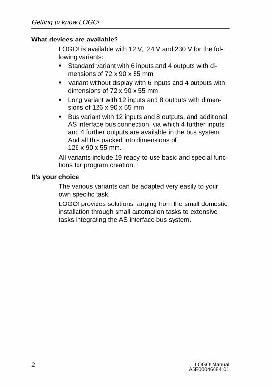
What devices are available?
LOGO! is available with 12 V, 24 V and 230 V for the fol-lowing variants:S Standard variant with 6 inputs and 4 outputs with di-
mensions of 72 x 90 x 55 mmS Variant without display with 6 inputs and 4 outputs with
dimensions of 72 x 90 x 55 mmS Long variant with 12 inputs and 8 outputs with dimen-
sions of 126 x 90 x 55 mmS Bus variant with 12 inputs and 8 outputs, and additional
AS interface bus connection, via which 4 further inputsand 4 further outputs are available in the bus system.And all this packed into dimensions of 126 x 90 x 55 mm.
All variants include 19 ready-to-use basic and special func-tions for program creation.
It’s your choice
The various variants can be adapted very easily to yourown specific task.
LOGO! provides solutions ranging from the small domesticinstallation through small automation tasks to extensivetasks integrating the AS interface bus system.
Getting to know LOGO!
3LOGO! ManualA5E00046684 01
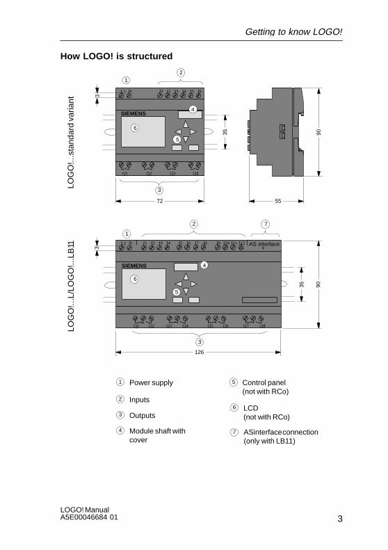
How LOGO! is structured
LOG
O!..
.sta
ndar
d va
riant
12
3
I4 I5 I6
Q1 Q2 Q3 Q4
SIEMENS
3
35
72
I1 I2 I3L1 N
4
6
5
90
55
LOG
O!..
.L/L
OG
O!..
.LB
11
1
2
3
126
35 90
L1 N I1 I2 I3 I4
Q1 Q3 Q4
SIEMENS
I5 I6
Q2 Q5 Q6 Q7 Q8
I7 I8 AS interface– +
I9 I10 I11 I12
3
4
5
6
7
1
2
4
3 Outputs
Power supply
Inputs
Module shaft withcover
5
6
7 ASinterface connection(only with LB11)
Control panel (not with RCo)
LCD (not with RCo)
Getting to know LOGO!

LOGO! ManualA5E00046684 01
4
How to recognize which LOGO! variant you have
LOGO!’s designation contains information on various char-acteristics:S 12: 12 V DC variantS 24: 24 V DC variantS 230: 115/230 V AC variantS R: Relay outputs (without R: Transistor output)S C: Integrated seven-day time switchS o: Variant without displayS L: Twice the number of outputs and inputsS B11: slave with AS interface bus connection
We also use icons to describe the different types of LOGO!They are used whenever information refers to only some ofthe LOGO! variants:
Standard variant with 6 inputs and 4 outputs with dimen-sions of 72 x 90 x 55 mm
Variant without display with 6 inputs and 4 outputs with di-mensions of 72 x 90 x 55 mm
..L variant with 12 inputs and 8 outputs with dimensions of126 x 90 x 55 mm
..B11 variant with 12 inputs and 8 outputs and additionalAS interface bus connection with 4 virtual inputs and4 virtual outputs with dimensions of 126 x 90 x 55 mm.
Getting to know LOGO!
5LOGO! ManualA5E00046684 01
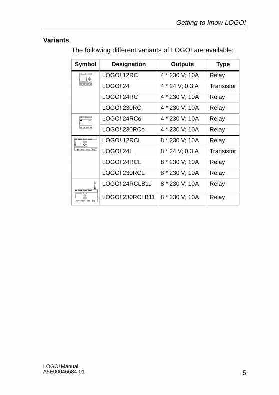
Variants
The following different variants of LOGO! are available:
Symbol Designation Outputs Type
LOGO! 12RC 4 * 230 V; 10A Relay
LOGO! 24 4 * 24 V; 0.3 A Transistor
LOGO! 24RC 4 * 230 V; 10A Relay
LOGO! 230RC 4 * 230 V; 10A Relay
LOGO! 24RCo 4 * 230 V; 10A Relay
LOGO! 230RCo 4 * 230 V; 10A Relay
LOGO! 12RCL 8 * 230 V; 10A Relay
LOGO! 24L 8 * 24 V; 0.3 A Transistor
LOGO! 24RCL 8 * 230 V; 10A Relay
LOGO! 230RCL 8 * 230 V; 10A Relay
LOGO! 24RCLB11 8 * 230 V; 10A Relay
LOGO! 230RCLB11 8 * 230 V; 10A Relay
Getting to know LOGO!

LOGO! ManualA5E00046684 01
6
Certification, recognition and approval
LOGO! has to UL, CSA and FM certification.S UL listing mark
Underwriters Laboratories (UL) toUL 508 standard , file no. 116536
S CSA–Certification–MarkCanadian Standard Association (CSA) tostandard C22.2 No. 142, file no. LR 48323
S FM approvalFactory Mutual (FM) Approval toStandard Class Number 3611, Class I, Division 2,Group A, B, C, D
!Warning
Personal injury and material damage may beincurred.
In potentially explosive areas, personal injury orproperty damage can result if you withdraw anyconnectors while the system is in operation.
Always ensure that the system is deenergizedbefore you disconnect LOGO! plug connectionsand associated components in potentially explo-sive areas.
LOGO! carries CE marking, complies with the VDE 0631and IEC1131 standards and has interference suppressionto EN 55011 (limit class B, class A for ASi bus operation).Shipbuilding certification has been granted.S ABS – American Bureau of ShippingS BV – Bureau VeritasS DNV – Det Norske VeritasS GL – Germanischer LloydS LRS – Lloyds Register of ShippingS PRS – Polski Rejestr Statków
LOGO! can therefore be used both in industry and athome.
Getting to know LOGO!
7LOGO! ManualA5E00046684 01
2 Installing and wiring LOGO!
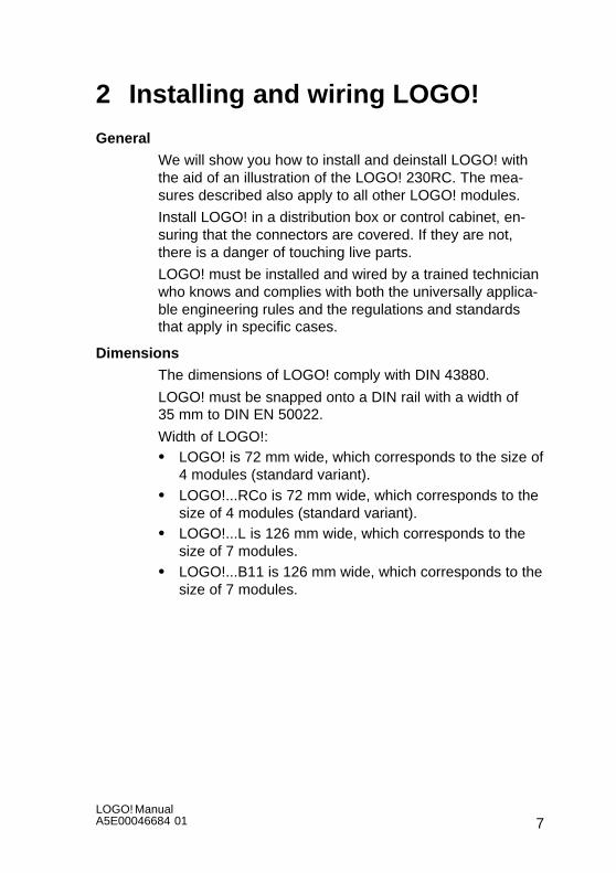
General
We will show you how to install and deinstall LOGO! withthe aid of an illustration of the LOGO! 230RC. The mea-sures described also apply to all other LOGO! modules.
Install LOGO! in a distribution box or control cabinet, en-suring that the connectors are covered. If they are not,there is a danger of touching live parts.
LOGO! must be installed and wired by a trained technicianwho knows and complies with both the universally applica-ble engineering rules and the regulations and standardsthat apply in specific cases.
Dimensions
The dimensions of LOGO! comply with DIN 43880.
LOGO! must be snapped onto a DIN rail with a width of35 mm to DIN EN 50022.
Width of LOGO!:S LOGO! is 72 mm wide, which corresponds to the size of
4 modules (standard variant).S LOGO!...RCo is 72 mm wide, which corresponds to the
size of 4 modules (standard variant).S LOGO!...L is 126 mm wide, which corresponds to the
size of 7 modules.S LOGO!...B11 is 126 mm wide, which corresponds to the
size of 7 modules.
LOGO! ManualA5E00046684 01
8
2.1 Installing/deinstalling LOGO!
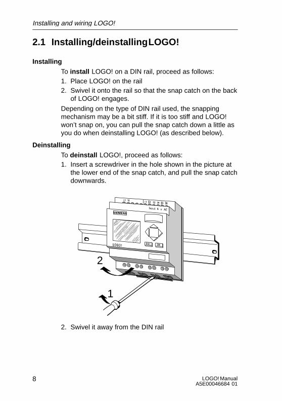
Installing
To install LOGO! on a DIN rail, proceed as follows:1. Place LOGO! on the rail2. Swivel it onto the rail so that the snap catch on the back
of LOGO! engages.
Depending on the type of DIN rail used, the snappingmechanism may be a bit stiff. If it is too stiff and LOGO!won’t snap on, you can pull the snap catch down a little asyou do when deinstalling LOGO! (as described below).
Deinstalling
To deinstall LOGO!, proceed as follows:1. Insert a screwdriver in the hole shown in the picture at
the lower end of the snap catch, and pull the snap catchdownwards.
1
2
2. Swivel it away from the DIN rail
Installing and wiring LOGO!

9LOGO! ManualA5E00046684 01
2.2 Wiring LOGO!
Use a screwdriver with a 3 mm head to wire LOGO!.
You don’t need wire end ferrules for the connectors. Youcan use wires up to the following sizes:S 1 x 2.5 mm2
S 2 x 1.5 mm2 for each second connector compartment
Connecting torque: 0.4...0.5 Nm or 3...4 LBin
2.2.1 Connecting the power supply
LOGO! 230 variants are suitable for line voltages with arating of 115 V AC and 230 V AC and LOGO! 24 variantsand 12 variants are suitable for 24 V DC and 12 V DC sup-ply voltage. LOGO! 24 RC/RCo is also suitable for a supplyvoltage of 24 V AC. Please note the technical specifica-tions in Appendix A that refer to the permissible voltagetolerances, mains frequencies and current consumption.
Note
Power failure might result for instance in an additionaledge after power restoration with edge-triggered specialfunctions.
Installing and wiring LOGO!
LOGO! ManualA5E00046684 01
10
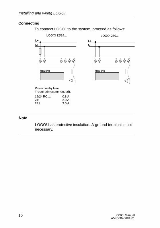
Connecting
To connect LOGO! to the system, proceed as follows:
L1L+
NM
LOGO! 12/24... LOGO! 230...
Protection by fuseif required (recommended).
12/24 RC...: 0.8 A24: 2.0 A24 L: 3.0 A
Note
LOGO! has protective insulation. A ground terminal is notnecessary.
Installing and wiring LOGO!
11LOGO! ManualA5E00046684 01
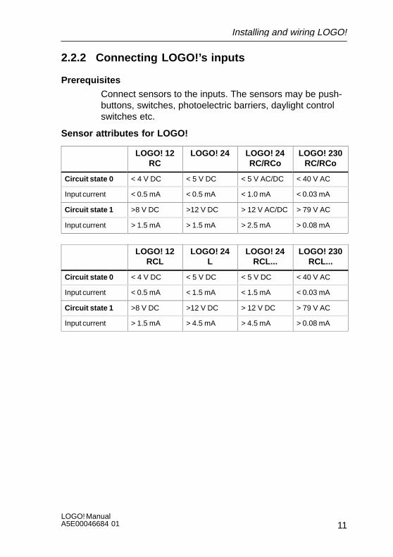
2.2.2 Connecting LOGO!’s inputs
Prerequisites
Connect sensors to the inputs. The sensors may be push-buttons, switches, photoelectric barriers, daylight controlswitches etc.
Sensor attributes for LOGO!
LOGO! 12RC
LOGO! 24 LOGO! 24RC/RCo
LOGO! 230RC/RCo
Circuit state 0 < 4 V DC < 5 V DC < 5 V AC/DC < 40 V AC
Input current < 0.5 mA < 0.5 mA < 1.0 mA < 0.03 mA
Circuit state 1 >8 V DC >12 V DC > 12 V AC/DC > 79 V AC
Input current > 1.5 mA > 1.5 mA > 2.5 mA > 0.08 mA
LOGO! 12RCL
LOGO! 24L
LOGO! 24RCL...
LOGO! 230RCL...
Circuit state 0 < 4 V DC < 5 V DC < 5 V DC < 40 V AC
Input current < 0.5 mA < 1.5 mA < 1.5 mA < 0.03 mA
Circuit state 1 >8 V DC >12 V DC > 12 V DC > 79 V AC
Input current > 1.5 mA > 4.5 mA > 4.5 mA > 0.08 mA
Installing and wiring LOGO!
LOGO! ManualA5E00046684 01
12
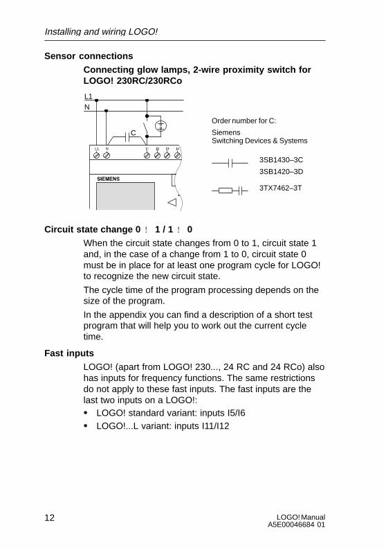
Sensor connections
Connecting glow lamps, 2-wire proximity switch forLOGO! 230RC/230RCo
L1N
NL1
C
3SB1430–3C
3SB1420–3D
3TX7462–3T
Order number for C:
SiemensSwitching Devices & Systems
Circuit state change 0 ! 1 / 1 ! 0
When the circuit state changes from 0 to 1, circuit state 1and, in the case of a change from 1 to 0, circuit state 0must be in place for at least one program cycle for LOGO!to recognize the new circuit state.
The cycle time of the program processing depends on thesize of the program.
In the appendix you can find a description of a short testprogram that will help you to work out the current cycletime.
Fast inputs
LOGO! (apart from LOGO! 230..., 24 RC and 24 RCo) alsohas inputs for frequency functions. The same restrictionsdo not apply to these fast inputs. The fast inputs are thelast two inputs on a LOGO!:S LOGO! standard variant: inputs I5/I6S LOGO!...L variant: inputs I11/I12
Installing and wiring LOGO!
13LOGO! ManualA5E00046684 01
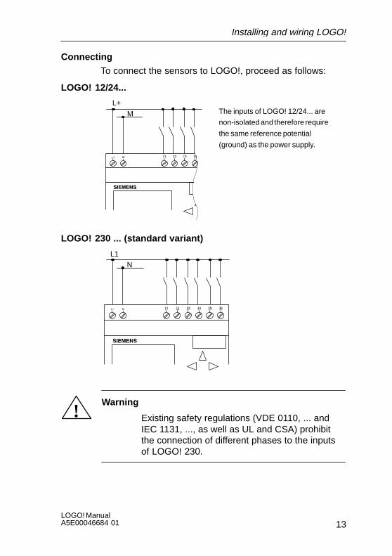
Connecting
To connect the sensors to LOGO!, proceed as follows:
LOGO! 12/24...
L+M The inputs of LOGO! 12/24... are
non-isolated and therefore require
the same reference potential
(ground) as the power supply.
LOGO! 230 ... (standard variant)
L1N
!Warning
Existing safety regulations (VDE 0110, ... andIEC 1131, ..., as well as UL and CSA) prohibitthe connection of different phases to the inputsof LOGO! 230.
Installing and wiring LOGO!
LOGO! ManualA5E00046684 01
14
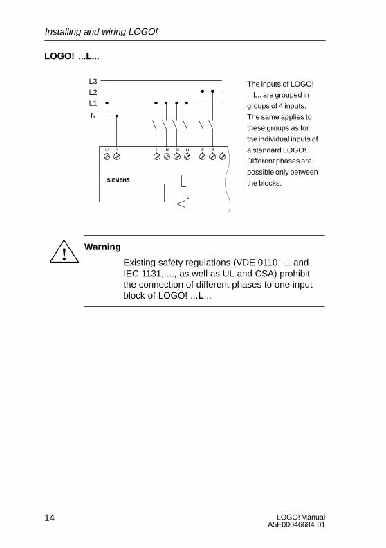
LOGO! ...L...
L1
N
L3
L2The inputs of LOGO!
...L.. are grouped in
groups of 4 inputs.
The same applies to
these groups as for
the individual inputs of
a standard LOGO!.
Different phases are
possible only between
the blocks.
! Warning
Existing safety regulations (VDE 0110, ... andIEC 1131, ..., as well as UL and CSA) prohibitthe connection of different phases to one inputblock of LOGO! ...L...
Installing and wiring LOGO!
15LOGO! ManualA5E00046684 01
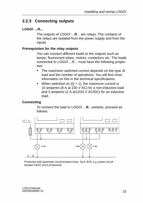
2.2.3 Connecting outputs
LOGO! ...R...
The outputs of LOGO! ...R... are relays. The contacts ofthe relays are isolated from the power supply and from theinputs.
Prerequisites for the relay outputs
You can connect different loads to the outputs such aslamps, fluorescent tubes, motors, contactors etc. The loadsconnected to LOGO! ...R... must have the following proper-ties:S The maximum switched current depends on the type of
load and the number of operations. You will find moreinformation on this in the technical specifications.
S When switched on (Q = 1), the maximum current is10 amperes (8 A at 230 V AC) for a non-inductive loadand 3 amperes (2 A at12/24 V AC/DC) for an inductiveload.
Connecting
To connect the load to LOGO! ...R...variants, proceed asfollows:
Protection with automatic circuit breaker (max. 16 A, B16, e.g. power circuitbreaker 5SX2 116-6 (if desired)
Installing and wiring LOGO!
LOGO! ManualA5E00046684 01
16
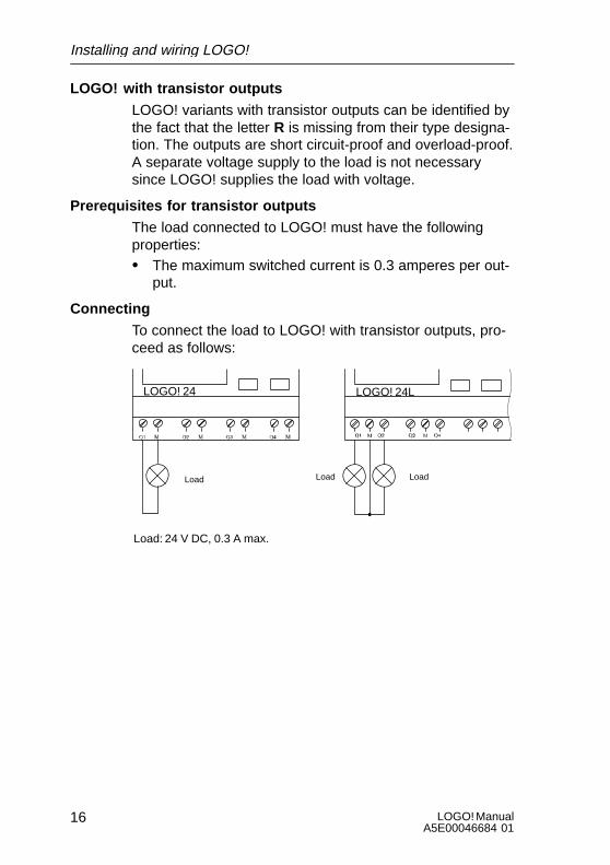
LOGO! with transistor outputs
LOGO! variants with transistor outputs can be identified bythe fact that the letter R is missing from their type designa-tion. The outputs are short circuit-proof and overload-proof.A separate voltage supply to the load is not necessarysince LOGO! supplies the load with voltage.
Prerequisites for transistor outputs
The load connected to LOGO! must have the followingproperties:S The maximum switched current is 0.3 amperes per out-
put.
Connecting
To connect the load to LOGO! with transistor outputs, pro-ceed as follows:
Load: 24 V DC, 0.3 A max.
LOGO! 24 LOGO! 24L
Load LoadLoad
Installing and wiring LOGO!

17LOGO! ManualA5E00046684 01
2.2.4 Connecting the ASi bus (LOGO! ...B11 only)
This section will be of interest to you if you want to connect LOGO!..B11 to the ASi bus.
LOGO!...B11
LOGO!...B11 can be integrated into a network as an ASislave. Using a two-wire lead you can then do the following:S Read in and process 4 additional inputs via the ASi bus.S Operate 4 additional outputs on one overlaid master of
the ASi bus.
Configure LOGO!...B11 in the ASi bus by means of the ASimaster you are using.
Prerequisites for operation on an ASi master
Please note: LOGO! ...B11 must be registered in the ASisystem, i. e. LOGO! is assigned an address by the busmaster. Please read Section 2.2.5 to find out how to do thiswith LOGO!.
!Caution
The ASI address can be changed at least10 times for all LOGO! ..LB11 variants.
Additional changes are not guaranteed.
Installing and wiring LOGO!
LOGO! ManualA5E00046684 01
18
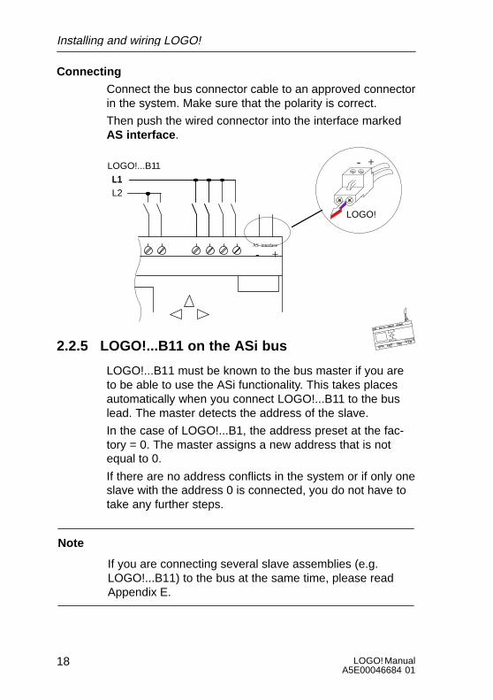
Connecting
Connect the bus connector cable to an approved connectorin the system. Make sure that the polarity is correct.
Then push the wired connector into the interface markedAS interface .
LOGO!
L1LOGO!...B11L1L2
+-
AS interface
- +
2.2.5 LOGO!...B11 on the ASi bus
LOGO!...B11 must be known to the bus master if you areto be able to use the ASi functionality. This takes placesautomatically when you connect LOGO!...B11 to the buslead. The master detects the address of the slave.
In the case of LOGO!...B1, the address preset at the fac-tory = 0. The master assigns a new address that is notequal to 0.
If there are no address conflicts in the system or if only oneslave with the address 0 is connected, you do not have totake any further steps.
Note
If you are connecting several slave assemblies (e.g.LOGO!...B11) to the bus at the same time, please readAppendix E.
Installing and wiring LOGO!
19LOGO! ManualA5E00046684 01
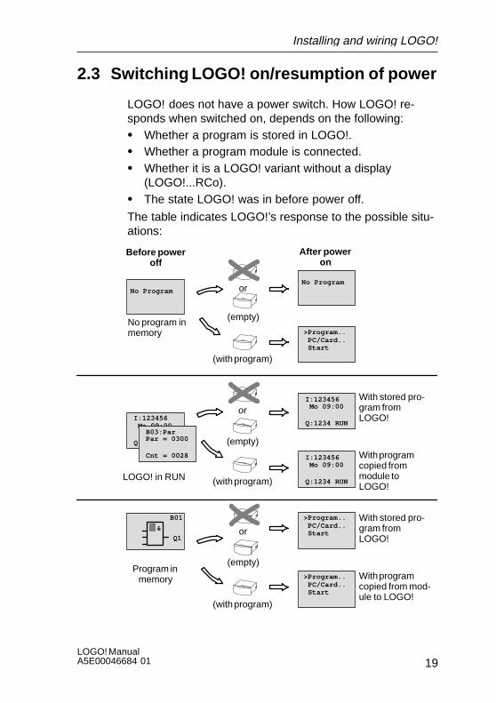
2.3 Switching LOGO! on/resumption of power
LOGO! does not have a power switch. How LOGO! re-sponds when switched on, depends on the following:S Whether a program is stored in LOGO!.S Whether a program module is connected.S Whether it is a LOGO! variant without a display
(LOGO!...RCo).S The state LOGO! was in before power off.
The table indicates LOGO!’s response to the possible situ-ations:
No ProgramNo Program
>Program.. PC/Card.. Start
I:123456
Q:1234 RUN
Mo 09:00
With stored pro-gram fromLOGO!
&
B01
Q1
No program inmemory
(empty)
(with program)
or
B03:Par
Cnt = 0028
Par = 0300 (empty)
(with program)
or
I:123456
Q:1234 RUN
Mo 09:00
I:123456
Q:1234 RUN
Mo 09:00
>Program.. PC/Card.. Start
(empty)
or
With programcopied frommodule toLOGO!
Before poweroff
After poweron
(with program)
>Program.. PC/Card.. Start
With stored pro-gram fromLOGO!
With programcopied from mod-ule to LOGO!
LOGO! in RUN
Program inmemory
Installing and wiring LOGO!
LOGO! ManualA5E00046684 01
20
Try to remember the 4 simple rules for starting LOGO!:1. If there is no program in LOGO! or on the connected
program module, LOGO! (with display) displays themessage: No Program.
2. If there is a program on the program module, it is auto-matically copied to LOGO!. If there is already a programin LOGO!, it is overwritten
3. If there is a program in LOGO! or on the program mod-ule, LOGO! adopts the operating status it had beforepower off. If you are using a variant without display(LOGO! ...RCo), it automatically changs from STOP toRUN (the LED changes from red to green).
4. If you have switched on retentivity for at least one func-tion or are using a function with retentivity permanentlyswitched on, its current values are retained at power off.
Note
If a power failure occurs while you are entering a program,you will find when the power is restored that LOGO! nolonger contains the program.
You should therefore back up your original program on aprogram module (card) or on a computer (LOGO!Soft,LOGO!Soft Comfort) before changing it.
Installing and wiring LOGO!

21LOGO! ManualA5E00046684 01
LOGO! operating statuses
LOGO! has 2 operating statuses: STOP and RUN
STOP RUN
S Display: ’No Program’ (notLOGO! ...RCo)
S Switch LOGO! to program-ming mode
S The LED lights up red(LOGO! ...RCo only)
S Display: Mask for monitor-ing the inputs and outputs(after START in the mainmenu)(not LOGO! ...RCo)
S Switch LOGO! to parame-terization mode(not LOGO! ...RCo)
S The LED lights up green(LOGO! ...RCo only)
Action by LOGO!:
S The inputs are not read.
S The program is not exe-cuted.
S The relay contacts are al-ways open or the transistoroutputs are switched off.
Action by LOGO!:
S LOGO! reads the state ofthe inputs.
S LOGO! calculates the stateof the outputs with the pro-gram.
S LOGO! switches the relays/transistor outputs on or off.
Installing and wiring LOGO!
LOGO! ManualA5E00046684 01
22
3 Programming LOGO!
The first steps with LOGO!
By programming we mean entering a circuit. A LOGO! pro-gramm is really no more than a circuit diagram representedin a different way.
We have changed the way it is represented to suitLOGO!’s display panel. In this chapter we will show youhow to use LOGO! to turn your applications into LOGO!programs.
Note
The LOGO! variants without a display, LOGO! 24RCo andLOGO! 230RCo, don’t have an operating unit. They aremainly intended for serial applications in small machineand apparatus construction.
LOGO!...RCo variants are not programmed on the device.Programs from LOGO! software or from memory modulesof other LOGO! devices are transferred into the device.
In the first section of the chapter a brief example will helpyou get to know how to use LOGO!.S First of all we will begin by introducing the two basic
terms connector and block , and show you what ismeant by these terms.
S In a second step we will develop a program from a sim-ple, conventional circuit.
S In the third step you can then enter this program directlyinto LOGO!.
After reading through only the first few pages of thismanual, you will already have stored your first executableprogram in LOGO!. Using suitable hardware (switches etc)you will then be able to carry out your first tests.

23LOGO! ManualA5E00046684 01
What else can you look forward to?
As you progress further through the chapter, you will ex-pand your first program and learn a number of techniquesyou can use to make changes to an existing program.
Finally in the third and last section of the chapter we willintroduce you to LOGO! in its entirety. This covers:S All the functions of LOGO!S Introduction to the menu structure of LOGO!
Programming LOGO!
LOGO! ManualA5E00046684 01
24
3.1 Connectors
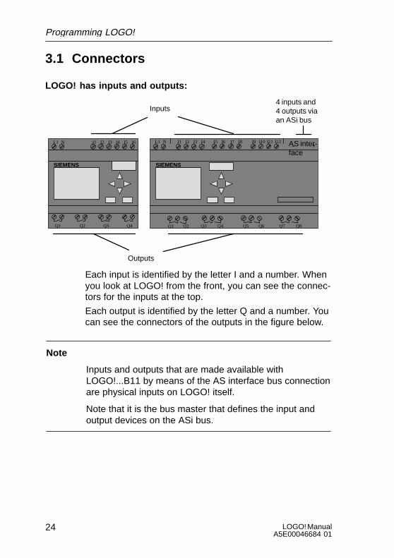
LOGO! has inputs and outputs:
L1 N I1 I2 I3 I4
Q1 Q3 Q4
SIEMENS
I5 I6
Q2 Q5 Q6 Q7 Q8
I7 I8 AS inter-face– +
I9 I10 I11 I12L1 N I1 I2 I3 I4 I5 I6
Q1 Q2 Q3 Q4
SIEMENS
Inputs
Outputs
4 inputs and4 outputs viaan ASi bus
Each input is identified by the letter I and a number. Whenyou look at LOGO! from the front, you can see the connec-tors for the inputs at the top.
Each output is identified by the letter Q and a number. Youcan see the connectors of the outputs in the figure below.
Note
Inputs and outputs that are made available withLOGO!...B11 by means of the AS interface bus connectionare physical inputs on LOGO! itself.
Note that it is the bus master that defines the input andoutput devices on the ASi bus.
Programming LOGO!

25LOGO! ManualA5E00046684 01
LOGO!’s connectors
The term connector refers to all connections and states inLOGO!.
The inputs and outputs can have the state ’0’ or ’1’. ’0’means there is no voltage at the input, ’1’ means that thereis. But that is unlikely to be new to you.
We introduced the connectors hi, lo and x, in order to facili-tate program entry for you. ’hi’ (high) has the fixed state ’1’and ’lo’ (low) has the fixed state ’0’.
If you don’t want to wire an input on a block, use the ’x’connector. You can find out what a block is on the nextpage.
LOGO! recognizes the following connectors:
Connec-tors
Inputs I1 to I6 I1 to I12 I1 to I12 and
Ia1 to Ia4 (ASinterface)
Outputs Q1 to Q4 Q1 to Q8 Q1 to Q8 and
Qa1 to Qa4(AS interface)
lo Signal with level ’0’ (off)
hi Signal with level ’1’ (on)
x An existing connection that is not used
Programming LOGO!

LOGO! ManualA5E00046684 01
26
3.2 Blocks and block numbers
In this chapter, we will describe how you can create exten-sive circuits with the aid of LOGO!’s elements and how theblocks are linked to each other and to the inputs and out-puts.
For this purpose, please turn to Section 3.3. There we de-scribe how to turn a conventional circuit into a LOGO! pro-gram.
Blocks
A block in LOGO! is a function which converts input infor-mation into output information. With earlier variants ofLOGO! you had to wire up the individual elements in thecontrol cabinet or terminal box.
When you program LOGO! you connect connectors withblocks. To do this, simply select the connection you requirefrom the Co menu (Co stands for connector).
Logic operations
The simplest blocks are logic operations:S ANDS ORS ...
I1I2
x
�1Inputs I1 and I2 are connected to theOR block. The last input of the blockis not used and is therefore markedwith an x.Q
We have made the special functions far more powerfulthan before:S Current impulse relayS CounterS On-delayS ....
You can find a complete list of all the functions of LOGO! inSection 3.7.
Programming LOGO!

27LOGO! ManualA5E00046684 01
Displaying a block in LOGO!’s display
The figure below shows a typical LOGO! display. As youcan see only block can be shown at a time. We have there-fore introduced block numbers to help you to check howthe circuit is structured.
B02w1
I2 Q1
B01
Display image of LOGO!
x
Block number –assigned byLOGO!
This shows that afurther block isconnected
Input
Connection is not required OutputBlock
Assigning a block number
Whenever you insert a block in a program, LOGO! assignsthat block a number.
LOGO! uses the block number to indicate the connectionsbetween the blocks. The block numbers are therefore chie-fly meant to help you find your way around the program.
I1I2I3
w1
B01
B02
B02w1
B03 Q1
B01
B01
Move around the program using the key
I4I5I6
w1
B01
There is a con-nection betweenthese blocks
Block number
Q1x
B03
Programming LOGO!

LOGO! ManualA5E00046684 01
28
The overview display shows you three displays of LOGO!,which together make up the program. As you can seeLOGO! links the blocks with one another by means of theblock numbers.
Advantages of the block numbers
You can connect almost any block to an input of the currentblock using its block number. In this way you can use theinterim results of logic or other operations more than once.This saves you the work required to enter things again aswell as memory space, and ensures that your circuit re-mains clear. In this case you have to know how LOGO! hasnamed the blocks.
Note
To make working with LOGO! particularly efficient, we rec-ommend that you draw up a diagram overview of the pro-gram. This will make it easier to create the program. Youcan then enter the block numbers assigned by LOGO! inthis diagram.
If you use the LOGO!Soft software to program LOGO!,you can display and print out a ladder program. You cancreate a functional block diagram of your program straightaway using LOGO!Soft Comfort.
Programming LOGO!
29LOGO! ManualA5E00046684 01
3.3 From circuit diagram to LOGO!
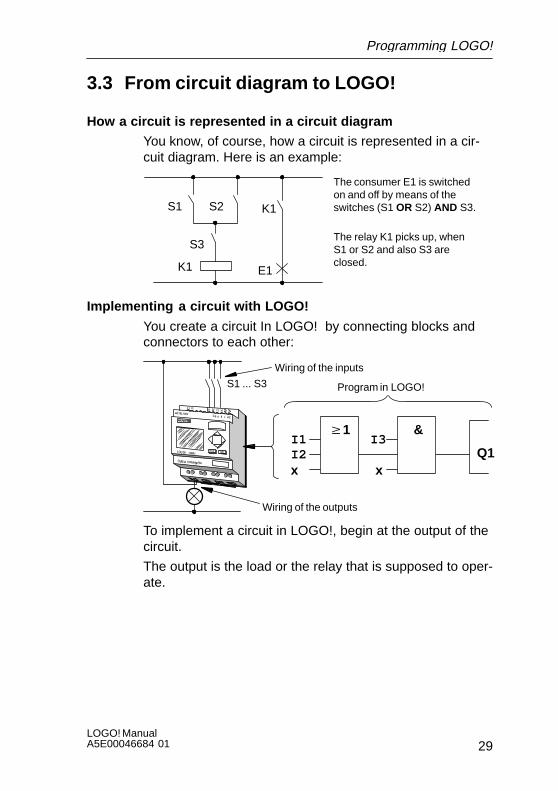
How a circuit is represented in a circuit diagram
You know, of course, how a circuit is represented in a cir-cuit diagram. Here is an example:
K1
S1 K1S2
E1
The consumer E1 is switchedon and off by means of theswitches (S1 OR S2) AND S3.
The relay K1 picks up, whenS1 or S2 and also S3 areclosed.
S3
Implementing a circuit with LOGO!
You create a circuit In LOGO! by connecting blocks andconnectors to each other:
S1 ... S3
Wiring of the inputs
I3
xQ1
&w1I1I2x
Program in LOGO!
Wiring of the outputs
To implement a circuit in LOGO!, begin at the output of thecircuit.
The output is the load or the relay that is supposed to oper-ate.
Programming LOGO!

LOGO! ManualA5E00046684 01
30
You convert the circuit to blocks. To do this, go through thecircuit from the output to the input:
Step 1: At output Q1 there is a series connection of thenormally open contact S3 with another circuit component.The series connection corresponds to an AND block:
I3
xQ1
&
Step 2: S1 and S2 are connected in parallel. The parallelconnection corresponds to an OR block:
I3
xQ1
&w1I1I2x
You have now provided a complete description of the circuitfor LOGO!. You now need to connect the inputs and out-puts to LOGO!.
Wiring
Connect switches S1 to S3 to the screw connectors ofLOGO!:S Connect S1 to connector I1 on LOGO!S Connect S2 to connector I2 on LOGO!S Connect S3 to connector I3 on LOGO!
Only 2 inputs of the OR block are used so the third inputmust be marked as unused. This is indicated by the x nextto it.
Likewise, only 2 inputs of the AND block are used. Thethird input is therefore also marked as ’unused’ by an xnext to it.
The output of the AND block controls the relay at outputQ1. Consumer E1 is connected at output Q1.
Programming LOGO!
31LOGO! ManualA5E00046684 01
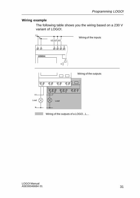
Wiring example
The following table shows you the wiring based on a 230 Vvariant of LOGO!.
L1N Wiring of the inputs
Wiring of the outputs
S1 S3S2
L1
N
Wiring of the outputs of a LOGO...L...
LoadLoad
Programming LOGO!
LOGO! ManualA5E00046684 01
32
3.4 The 4 golden rules for working withLOGO!
Rule 13-finger grip
S Enter the circuit in programming mode. Switch to pro-gramming mode by pressing the 3 keys , and OK atthe same time.
S Change the values of times and parameters in parame-terization mode. Switch to parameterization mode bypressing the 2 keys ESC and OK at the same time.
Rule 2Outputs and inputs
S Always enter a circuit from output to input.S You can connect an output to several inputs, but not
several outputs to one input.S You can’t connect an output to a preceding input within
a program path. Insert markers or outputs in such cases(recursions).
Programming LOGO!

33LOGO! ManualA5E00046684 01
Rule 3Cursor and cursor movement
The following applies when entering a circuit:S When the cursor appears in the form of an underscore,
you can move the cursor :– Use the keys , , or to move the cursor in the
circuit.– Press OK to select a connector/block.– Press ESC to exit circuit input.
S When the cursor appears in the form of a solid block,you should select a connector/block – Use the keys or to select a connector/block.– Press OK to accept a selection.– Press ESC to go back one step.
Rule 4Planning
S Before you enter a circuit, draw up a complete plan of iton paper or program LOGO! directly using LOGO!Softor LOGO!Soft Comfort.
S LOGO! can only store complete programs. If you enteran incomplete program, LOGO! is not able to exit Pro-gramming mode.
Programming LOGO!

LOGO! ManualA5E00046684 01
34
3.5 Overview of LOGO!’s menus
>Program.. PC/Card.. Start
>Edit Prg Clear Prg Set Clock ASi_BUS..
>PC LOGO LOGO³Card Card ³LOGO
Main menu Programming menu
PC/card menu
>Set Clock Set Param
OK
OK
ESC
ESC
Parameterization menu
Programming mode
Parameterization mode
Programming LOGO!
35LOGO! ManualA5E00046684 01
3.6 Entering and starting a program
You have designed a circuit and now want to enter it inLOGO!. The example below illustrates how to do this.
3.6.1 Switching to programming mode
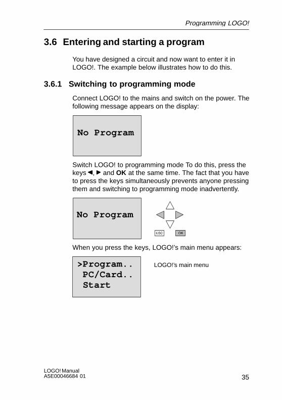
Connect LOGO! to the mains and switch on the power. Thefollowing message appears on the display:
No Program
Switch LOGO! to programming mode To do this, press thekeys , and OK at the same time. The fact that you haveto press the keys simultaneously prevents anyone pressingthem and switching to programming mode inadvertently.
No Program
When you press the keys, LOGO!’s main menu appears:
>Program.. PC/Card.. Start
LOGO!’s main menu
Programming LOGO!
LOGO! ManualA5E00046684 01
36
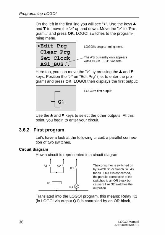
On the left in the first line you will see ”>”. Use the keys and to move the ”>” up and down. Move the ”>” to ”Pro-gram..” and press OK. LOGO! switches to the program-ming menu.
>Edit Prg Clear Prg Set Clock ASi_BUS..
LOGO!’s programming menu
The ASi bus entry only appearswith LOGO!...LB11 variants
Here too, you can move the ”>” by pressing the and keys. Position the ”>” on ”Edit Prg” (i.e. to enter the pro-gram) and press OK. LOGO! then displays the first output:
LOGO!’s first output
Q1
Use the and keys to select the other outputs. At thispoint, you begin to enter your circuit.
3.6.2 First program
Let’s have a look at the following circuit: a parallel connec-tion of two switches.
Circuit diagramHow a circuit is represented in a circuit diagram
K1
S1K1
S2
E1
The consumer is switched onby switch S1 or switch S2. Asfar as LOGO! is concerned,the parallel connection of theswitches is an OR block be-cause S1 or S2 switches theoutput on.
Translated into the LOGO! program, this means: Relay K1(in LOGO! via output Q1) is controlled by an OR block.
Programming LOGO!

37LOGO! ManualA5E00046684 01
ProgramI1 and I2 are connected to the input of the OR block, S1 toI1 and S2 to I2.Thus, the program in LOGO! looks like this:
I1
I2
xQ1
�1
Wiring
The wiring is as follows:
L1 N I1 I2 I3 I4 I5 I6
Q1 Q2 Q3 Q4
SIEMENS
L1
N
S1 S2
L
N
Switch S1 acts on input I1 and switch S2 on input I2. Theconsumer is connected to relay Q1.
Programming LOGO!

LOGO! ManualA5E00046684 01
38
3.6.3 Entering the program
Let’s enter the program now (from the output to the input).Initially, LOGO! displays the output:
LOGO!’s first output
Q1
The Q of Q1 is underlined. This underlining is the cursor .The cursor indicates your current position in the program.You can move the cursor by pressing the , , and keys. Now press the key . The cursor moves to the left.
The cursor indicates your position inthe program.
Q1–
At this point, enter only the first block (the OR block). PressOK to switch to input mode.
The cursor appears in the form of asolid block: you can select a connectoror block.
Q1Co
The cursor no longer appears in the form of an underline;instead it appears as a solid block that flashes on and off.At the same time, LOGO! offers you the first list for selec-tion.
Select the BF list (by pressing until BF appears) andpress OK. LOGO! then displays the first block in the list ofbasic functions (BF):
Programming LOGO!
39LOGO! ManualA5E00046684 01
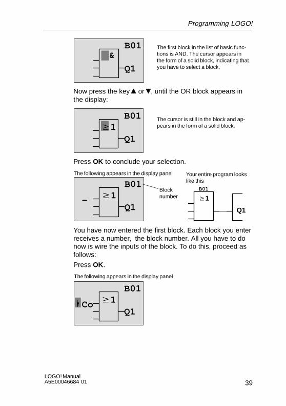
The first block in the list of basic func-tions is AND. The cursor appears inthe form of a solid block, indicating thatyou have to select a block.
&B01
Q1
Now press the key or , until the OR block appears inthe display:
w1B01
Q1
The cursor is still in the block and ap-pears in the form of a solid block.
Press OK to conclude your selection.
w1
The following appears in the display panel
B01
Q1
B01
w1
Q1
Your entire program lookslike this
Blocknumber–
You have now entered the first block. Each block you enterreceives a number, the block number. All you have to donow is wire the inputs of the block. To do this, proceed asfollows:
Press OK.
w1
The following appears in the display panel
B01
Q1Co
Programming LOGO!
LOGO! ManualA5E00046684 01
40
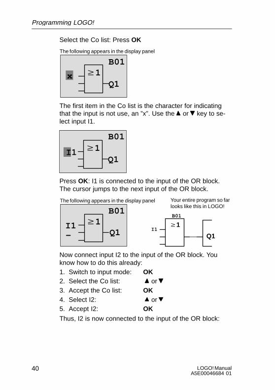
Select the Co list: Press OK
w1
The following appears in the display panel
B01
Q1x
The first item in the Co list is the character for indicatingthat the input is not use, an ”x”. Use the or key to se-lect input I1.
w1Q1
I1
B01
Press OK: I1 is connected to the input of the OR block.The cursor jumps to the next input of the OR block.
w1
The following appears in the display panel
B01
Q1w1
Q1
Your entire program so farlooks like this in LOGO!
I1 I1
B01
–
Now connect input I2 to the input of the OR block. Youknow how to do this already:1. Switch to input mode: OK2. Select the Co list: or 3. Accept the Co list: OK4. Select I2: or 5. Accept I2: OK
Thus, I2 is now connected to the input of the OR block:
Programming LOGO!

41LOGO! ManualA5E00046684 01
w1
The following appears in the display panel
B01
Q1w1
Q1
I1 I1
B01
I2I2
Your entire program so farlooks like this in LOGO!
We don’t need the last input of the OR block in this pro-gram. In a LOGO! program, you mark an input that is notused with an ”x”, so now enter the ’x’ (you know the princi-ple already):1. Switch to input mode: OK2. Select the Co list: or 3. Accept the Co list: OK4. Select x: or 5. Accept x: OK
Thus, all the block’s inputs are now wired. As far as LOGO!is concerned, the program is now complete. LOGO! returnsto output Q1.
The following appears in the display panel
w1
Q1
Your program looks like this
I1
B01
I2Q1B01x
If you want to have another look at your first program, youcan use the or key to move the cursor through the pro-gram.
Programming LOGO!

LOGO! ManualA5E00046684 01
42
But we are going to exit program input now. To do this, pro-ceed as follows:1. Return to the programming menu: ESC
If this doesn’t return you to the programming menu, youhave not wired a block completely. LOGO! displays thepoint in the program at which you forgot something (LOGO!only accepts completed programs, which is very much inyour interests). Also refer to page 53.
Note
LOGO! has now stored your program permanently, so thatit will not be lost in the event of a power failure. The pro-gram is stored in LOGO! until you expressly delete it byentering the appropriate command.
2. Return to the main menu:ESC
Switching LOGO! to RUN 3. Move ’>’ to ’Start’: or 4. Accept Start: OK
LOGO! switches to RUN. In RUN LOGO! displays the fol-lowing:
LOGO!’s display panel in RUN
State of the inputs
Current time(variants with time switch only)
LOGO! is in RUN
State of the outputs
I:123456 Mo 09:00
Q:1234 RUN
I:12345678
Q:12345678 Mo 09:00
9 10 11 12
ASi_BusIa : 1234Qa : 1234Bus: On
State of the ASi inputs
State of the ASi outputs
State of the ASi bus
Programming LOGO!
43LOGO! ManualA5E00046684 01
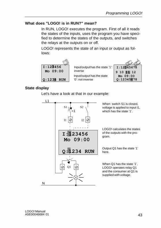
What does ”LOGO! is in RUN?” mean?
In RUN, LOGO! executes the program. First of all it readsthe states of the inputs, uses the program you have speci-fied to determine the states of the outputs, and switchesthe relays at the outputs on or off.
LOGO! represents the state of an input or output as fol-lows:
Input/output has the state ’1’:inverse
Input/output has the state’0’: not inverse
Mo 09:00
I:12345678
9 10 11 12
I:123456 Mo 09:00
Q:1234 RUN Q:12345678
State display
Let’s have a look at that in our example:
I:123456Mo 09:00
Q:1234 RUN
L1
N
S1 S2=1
When switch S1 is closed,voltage is applied to input I1,which has the state ’1’.
LOGO! calculates the statesof the outputs with the pro-gram.
Output Q1 has the state ’1’here.
When Q1 has the state ’1’,LOGO! operates relay Q1and the consumer at Q1 issupplied with voltage.
I1 I2
Q1
Programming LOGO!

LOGO! ManualA5E00046684 01
44
The next step
You have now successfully entered your first circuit.
In the next section, we will show you how to make changesto existing programs and use special functions in them.
Programming LOGO!
45LOGO! ManualA5E00046684 01
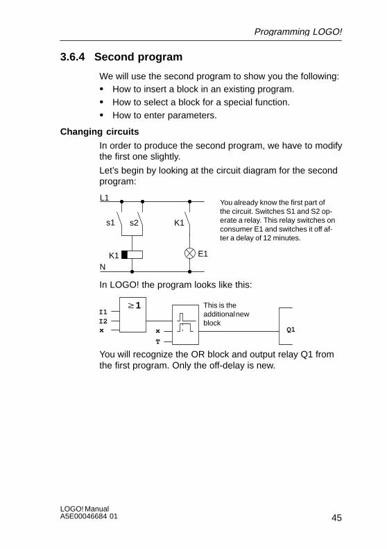
3.6.4 Second program
We will use the second program to show you the following:S How to insert a block in an existing program.S How to select a block for a special function.S How to enter parameters.
Changing circuits
In order to produce the second program, we have to modifythe first one slightly.
Let’s begin by looking at the circuit diagram for the secondprogram:
L1
N
s1 s2
You already know the first part ofthe circuit. Switches S1 and S2 op-erate a relay. This relay switches onconsumer E1 and switches it off af-ter a delay of 12 minutes.
K1
K1 E1
In LOGO! the program looks like this:
w1
Q1
I1I2x x
T
This is theadditional newblock
You will recognize the OR block and output relay Q1 fromthe first program. Only the off-delay is new.
Programming LOGO!

LOGO! ManualA5E00046684 01
46
Editing a program
Switch LOGO! to programming mode
To do this, proceed as follows:1. Switch LOGO! to programming mode:
( , and OK at the same time).2. Select ”Program..” from the main menu
(by moving ’>’ to “Program..” and press OK)3. Select ”Edit Prg..” from the programming menu
(by moving ’>’ to “Edit Prg..” and press OK)
You can now modify the existing program.
Inserting an additional block in a program
Move the cursor to the B of B01 (B01 is the block numberof the OR block).
Q1B01
Move the cursor:Press
At this point we insert the new block. Press OK.
Q1BN
LOGO! displays the BN list.
Select the SF list (B key).
Q1SF
The SF list contains the blocksfor the special functions
Press OK.
Programming LOGO!

47LOGO! ManualA5E00046684 01
The block of the first special function appears:
TrgT Q1
When you select a block for a special or basicfunction, LOGO! displays the block of thefunction. The cursor is in the block and ap-pears in the form of a solid block. Use the Bor Y to select the desired block.
Select the desired block (off-delay, see next diagram) andpress OK:
R
The inserted block receives the block num-ber B02. Block B01, which has been con-nected up to now to Q1, is automaticallyconnected to the uppermost input of the in-serted block. The cursor is positioned at theuppermost input of the inserted block.
B01
TQ1
B02
The off-delay block has 3 inputs. The uppermost input isthe trigger input (Trg). Use this input to start the off-delay.In our example, the off-delay is started by the OR blockB01. Reset the time and outputs using the reset input andset the time for the off-delay using the T parameter.
In our example, we don’t use the reset input of the off-delay. We wire it with ’x’. You learned how to do this in thefirst program, but just to remind you, here is the procedureagain:1. Position the cursor under the R: or 2. Switch to input mode: OK3. Select the Co list: or 4. Accept the Co list: OK5. Select x: or 6. Accept x: OK
xB01
TQ1
B02The display should now look like this:
Programming LOGO!

LOGO! ManualA5E00046684 01
48
Parameterizing a block
Now enter the time T for the off-delay:1. If the cursor is not yet under the T, move it there:
or 2. Switch to input mode: OK
LOGO! displays the parameter window for parameters:
B02: the parameter of blockB02 T: is a time
+ Means: the parameter isdisplayed in parameteriza-tion mode and can be modi-fied there
B02:TT=00.00s+
Time value Time unit
The cursor appears on the first position of the time value.
To change the time value, proceed as follows:S Use the keys and to move the cursor to different
positions.S Use the keys and to change the value.S When you have entered the time value, press OK.
Setting the time
Set the time T = 12:00 minutes:1. Move the cursor to the first position:
or 2. Select ’1’:
or 3. Move the cursor to the second position:
or 4. Select ’2’:
or 5. Move the cursor to the unit:
or 6. Select the unit m for minutes:
or
Programming LOGO!
49LOGO! ManualA5E00046684 01
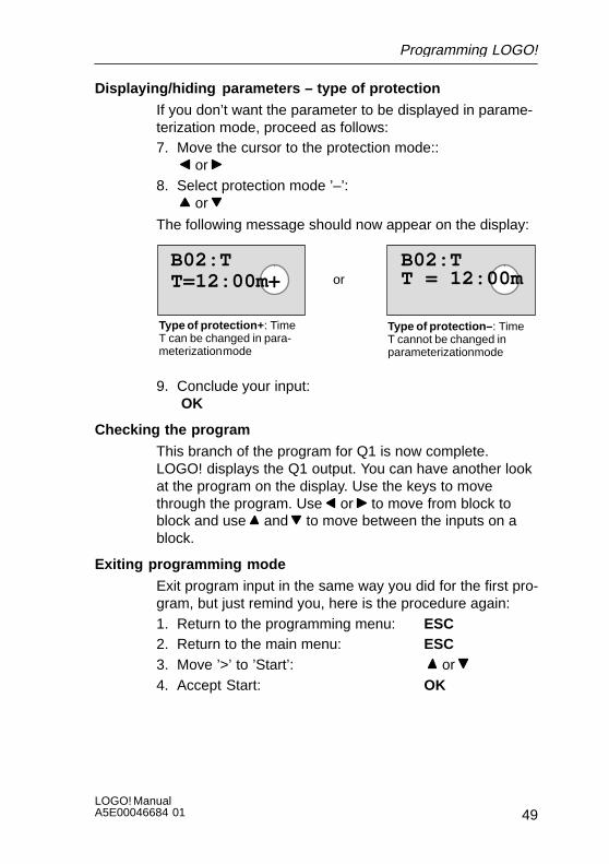
Displaying/hiding parameters – type of protection
If you don’t want the parameter to be displayed in parame-terization mode, proceed as follows:7. Move the cursor to the protection mode::
or 8. Select protection mode ’–’:
or
The following message should now appear on the display:
B02:TT=12:00m+
B02:TT = 12:00mor
Type of protection+ : TimeT can be changed in para-meterization mode
Type of protection– : TimeT cannot be changed inparameterization mode
9. Conclude your input: OK
Checking the program
This branch of the program for Q1 is now complete.LOGO! displays the Q1 output. You can have another lookat the program on the display. Use the keys to movethrough the program. Use or to move from block toblock and use and to move between the inputs on ablock.
Exiting programming mode
Exit program input in the same way you did for the first pro-gram, but just remind you, here is the procedure again:1. Return to the programming menu: ESC2. Return to the main menu: ESC3. Move ’>’ to ’Start’: or 4. Accept Start: OK
Programming LOGO!

LOGO! ManualA5E00046684 01
50
LOGO! is now in RUN again:
I:123456
Q:1234 RUN
Mo 09:00
Programming LOGO!
51LOGO! ManualA5E00046684 01
3.6.5 Deleting a block
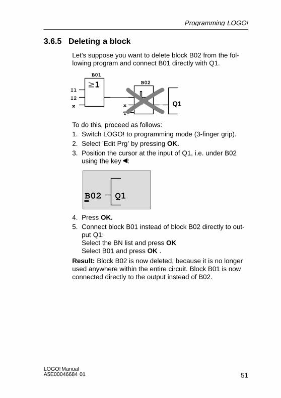
Let’s suppose you want to delete block B02 from the fol-lowing program and connect B01 directly with Q1.
Q1
I1
I2
x x
T
B01
B02
To do this, proceed as follows:1. Switch LOGO! to programming mode (3-finger grip).2. Select ’Edit Prg’ by pressing OK.3. Position the cursor at the input of Q1, i.e. under B02
using the key :
B02 Q1
4. Press OK.5. Connect block B01 instead of block B02 directly to out-
put Q1:Select the BN list and press OKSelect B01 and press OK .
Result: Block B02 is now deleted, because it is no longerused anywhere within the entire circuit. Block B01 is nowconnected directly to the output instead of B02.
Programming LOGO!
LOGO! ManualA5E00046684 01
52
3.6.6 Deleting a number of interconnected blocks
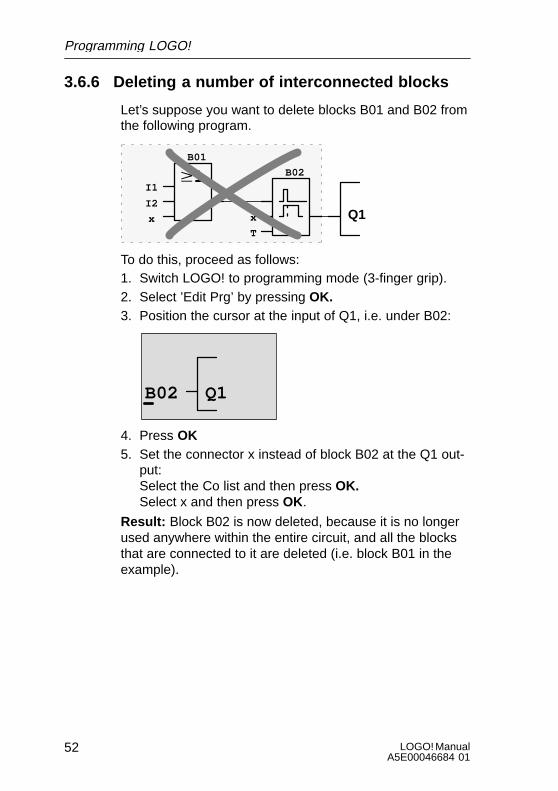
Let’s suppose you want to delete blocks B01 and B02 fromthe following program.
Q1
I1
I2
x x
T
B01
B02
To do this, proceed as follows:1. Switch LOGO! to programming mode (3-finger grip).2. Select ’Edit Prg’ by pressing OK.3. Position the cursor at the input of Q1, i.e. under B02:
B02 Q1
4. Press OK5. Set the connector x instead of block B02 at the Q1 out-
put:Select the Co list and then press OK. Select x and then press OK.
Result: Block B02 is now deleted, because it is no longerused anywhere within the entire circuit, and all the blocksthat are connected to it are deleted (i.e. block B01 in theexample).
Programming LOGO!

53LOGO! ManualA5E00046684 01
3.6.7 Correcting typing errors
It is easy to correct typing errors in LOGO!:S If you have not yet concluded input, you can use ESC
to go back a step.S If you have already concluded input, simply start again,
as follows:1. Move the cursor to the location of the error.2. Switch to input mode: OK3. Enter the correct wiring for the input.
You can only replace one block with another if the newblock has exactly the same number of inputs as the oldone. However, you can delete the old block and insert anew one. You can insert whichever block you like.
3.6.8 ”?” on the display
If you have entered a program and want to exit “Edit Prg”with ESC, LOGO! checks whether you have wired all theinputs of all the blocks correctly. If you have forgotten aninput or parameter, LOGO! displays the first place at whichyou have forgotten something and marks with a questionmark all those inputs and parameters that have not beenwired.
R ?
You have not yet wired the in-put here
B01
T ?Q1
B02
You have not yet specified avalue for the parameter
Wire the input and enter a value for the parameter. You canthen exit “Edit Prg” by pressing ESC .
Programming LOGO!

LOGO! ManualA5E00046684 01
54
3.6.9 Deletinga program
To delete a program, proceed as follows:1. Switch LOGO! to programming mode:
, and OK at the same time
>Program.. PC/Card.. Start
2. Move the ’>’ or to ’Program..’ using the or key andpress OK
>Edit Prg Clear Prg Set Clock
LOGO! switches to the programmingmenu.
3. Move the ’>’ to ”Clear Prg”: or
4. Accept ’Clear Prg’: OK
Clear Prg>No Yes
To prevent you from inadvertently delet-ing the program, we have included anadditional query.
If you do not want to delete the program, leave the ’>’ on’No’ and press OK.
If you are sure that you want to delete the program storedin LOGO!, proceed as follows:5. Move the ’>’ to Yes:
or 6. Press OK. LOGO! deletes the program.
Programming LOGO!

55LOGO! ManualA5E00046684 01
3.7 Functions
LOGO! offers you a number of elements in programmingmode. So that you don’t lose track of things, we have di-vided these elements into lists. These lists are:S ±Co: List of connectors (Connector)
(see Section 3.8)S ±BF: List of the basic functions AND, OR, ...
(see Section 3.9)S ±SF: List of the special functions
(see Section 3.10)S ±BN: List of the blocks already configured in the circuit
and reusable
Contents of the lists
All the lists display elements available in LOGO!. Normally,these are all the connectors, all the basic functions and allthe special functions that the respective LOGO! variantknows. These elements also include all the blocks that youhave already generated in LOGO! before you call up the±BN list.
When LOGO! no longer displays everything
LOGO! no longer displays all elements if:S No further block must be inserted.
In this case, there is either no more memory availableor the maximum number of possible blocks has beenreached (56).
S A special block would use more memory than is stillavailable in LOGO!.
S The resulting number of blocks connected in serieswould exceed 7 (see Section 3.11).
Programming LOGO!
LOGO! ManualA5E00046684 01
56
3.8 Constants and connectors – (Co)
Constants and connectors (Co) describe inputs, outputs,markers and fixed voltage levels (constants).
Inputs
Inputs are identified by the letter I. The input numbers (I1,I2, ...) correspond to the numbers of the input connectorson LOGO!.
Inputs Ia1 to Ia4 are also available for communication viathe ASi bus in LOGO! variants with an AS interface con-nection (LOGO!...B11).
Outputs
Outputs are identified by the letter Q. The output numbers(Q1, Q2, ...) correspond to the numbers of the output con-nectors on LOGO!.
Outputs Qa1 to Qa4 are also available for communicationvia the ASi bus with LOGO! variants with an AS interfaceconnection (LOGO!...B11).
Markers
Markers are identified by the letter M. Markers are virtualoutputs that have the same value at their output as theyhave at their input. There are 4 markers (M1 ... M4) avail-able in LOGO!.
By using markers you can exceed the maximum number ofconsecutive blocks.
Note
The signal applied at the marker’s output is always that ofthe last program cycle. The signal is not changed within aprogram cycle.
Programming LOGO!

57LOGO! ManualA5E00046684 01
Levels
Voltage levels are identified by hi and lo . If a block is sup-posed to have the state “1” = hi or “0” = continuously, theinput is wired with the fixed level or the constant hi or lovalue.
Open connectors
If the connector pin of a block is not to be wired, this is indi-cated with an x.
Programming LOGO!
LOGO! ManualA5E00046684 01
58
3.9 Basic functions – BF
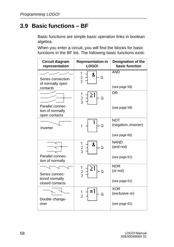
Basic functions are simple basic operation links in booleanalgebra.
When you enter a circuit, you will find the blocks for basicfunctions in the BF list. The following basic functions exist:
Circuit diagramrepresentation
Representation inLOGO!
Designation of thebasic function
Series connection of normally opencontacts
AND
(see page 59)
Parallel connec-tion of normallyopen contacts
OR
(see page 59)
Inverter
NOT (negation, inverter)
(see page 60)
Parallel connec-tion of normallyl d
NAND (and not)
(see page 61)
Series connec-tionof normallyclosed contacts
NOR (or not)
(see page 61)
Double change-over
XOR (exclusive or)
(see page 62)
Programming LOGO!

59LOGO! ManualA5E00046684 01
3.9.1 AND
The series connection of a number ofnormally open contacts is repre-sented in a circuit diagram as follows:
Symbol in LOGO!:
The output of the AND only adopts the state 1 if all the in-puts have the state 1 (i.e. they are closed).
If an input pin of this block is not wired (x), then the follow-ing applies to the input: x = 1.
Logic table for AND
1 2 3 Q
0 0 0 00 0 1 00 1 0 00 1 1 01 0 0 01 0 1 01 1 0 01 1 1 1
3.9.2 OR
The parallel connection of a number of normally opencontacts is represented in a circuit diagram as follows:
Symbol in LOGO!:
The output of the OR adopts the state 1 if at least oneinput has the state 1 (i.e. it is closed).
If an input pin of this block is not wired (x), then the follow-ing applies to the input: x = 0.
Programming LOGO!
LOGO! ManualA5E00046684 01
60
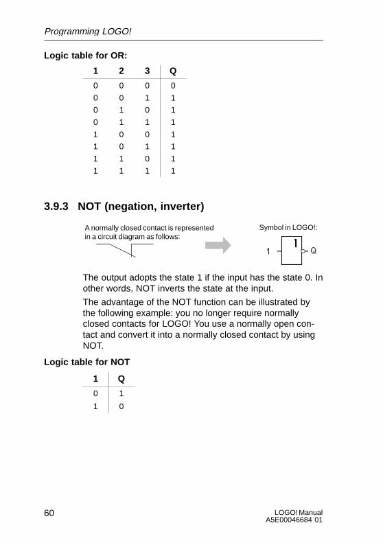
Logic table for OR:
1 2 3 Q
0 0 0 0
0 0 1 1
0 1 0 1
0 1 1 1
1 0 0 1
1 0 1 1
1 1 0 1
1 1 1 1
3.9.3 NOT (negation, inverter)
A normally closed contact is representedin a circuit diagram as follows:
Symbol in LOGO!:
The output adopts the state 1 if the input has the state 0. Inother words, NOT inverts the state at the input.
The advantage of the NOT function can be illustrated bythe following example: you no longer require normallyclosed contacts for LOGO! You use a normally open con-tact and convert it into a normally closed contact by usingNOT.
Logic table for NOT
1 Q
0 1
1 0
Programming LOGO!
61LOGO! ManualA5E00046684 01
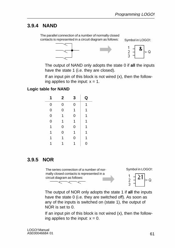
3.9.4 NAND
The parallel connection of a number of normally closedcontacts is represented in a circuit diagram as follows: Symbol in LOGO!:
The output of NAND only adopts the state 0 if all the inputshave the state 1 (i.e. they are closed).
If an input pin of this block is not wired (x), then the follow-ing applies to the input: x = 1.
Logic table for NAND
1 2 3 Q
0 0 0 1
0 0 1 1
0 1 0 1
0 1 1 1
1 0 0 1
1 0 1 1
1 1 0 1
1 1 1 0
3.9.5 NOR
The series connection of a number of nor-mally closed contacts is represented in acircuit diagram as follows:
Symbol in LOGO!:
The output of NOR only adopts the state 1 if all the inputshave the state 0 (i.e. they are switched off). As soon asany of the inputs is switched on (state 1), the output ofNOR is set to 0.
If an input pin of this block is not wired (x), then the follow-ing applies to the input: x = 0.
Programming LOGO!
LOGO! ManualA5E00046684 01
62
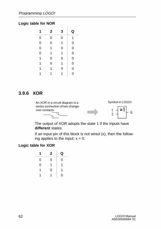
Logic table for NOR
1 2 3 Q
0 0 0 1
0 0 1 0
0 1 0 0
0 1 1 0
1 0 0 0
1 0 1 0
1 1 0 0
1 1 1 0
3.9.6 XOR
An XOR in a circuit diagram is aseries connection of two change-over contacts:
Symbol in LOGO!:
The output of XOR adopts the state 1 if the inputs have different states.
If an input pin of this block is not wired (x), then the follow-ing applies to the input: x = 0.
Logic table for XOR
1 2 Q
0 0 0
0 1 1
1 0 1
1 1 0
Programming LOGO!
63LOGO! ManualA5E00046684 01
3.10 Special functions – SF
Special functions include time functions, retentivity and var-ious parameterization options to adapt the program to yourindividual requirements.
3.10.1 Parameter T and time response
Parameter T
In some of the following special functions it is possible toparameterize a T time value. Note the following when youset the time:
Note
Always specify a time for T w 0.10 s. For T = 0.05 s and T= 0.00 s the time T is not defined.
Accuracy of T
All electronic components have minute differences. Thiscan result in deviations in the set time (T). In LOGO! themaximum deviation is 1 %.
Example:
In 1 hour (3600 seconds) the deviation is 1% i.e. "36 sec-onds.
In 1 minute the deviation is therefore only " 0.6 seconds.
Accuracy of the time switch
To make sure that this deviation doesn’t result in the clockin C variants running inaccurately, the time switch is regu-larly compared with a high-precision time base and ad-justed accordingly.
This results in a maximum time error of $5s per day.
The year 2000 is not a problem for LOGO!, incidentally.
Programming LOGO!
LOGO! ManualA5E00046684 01
64
3.10.2 Retentivity
The switching states and counter values can be kept reten-tively in the special functions. To do this, retentivity must beswitched on in the relevant function.
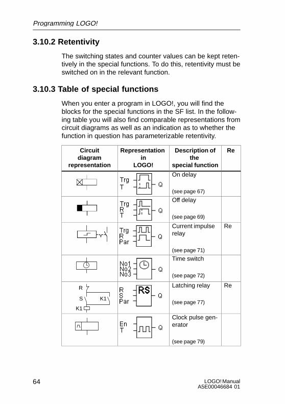
3.10.3 Table of special functions
When you enter a program in LOGO!, you will find theblocks for the special functions in the SF list. In the follow-ing table you will also find comparable representations fromcircuit diagrams as well as an indication as to whether thefunction in question has parameterizable retentivity.
Circuitdiagram
representation
Representation in
LOGO!
Description ofthe
special function
Re
On delay
(see page 67)
Off delay
(see page 69)
Current impulserelay
(see page 71)
Re
Time switch
(see page 72)
R
S
K1
K1
Latching relay
(see page 77)
Re
Clock pulse gen-erator
(see page 79)
Programming LOGO!
65LOGO! ManualA5E00046684 01
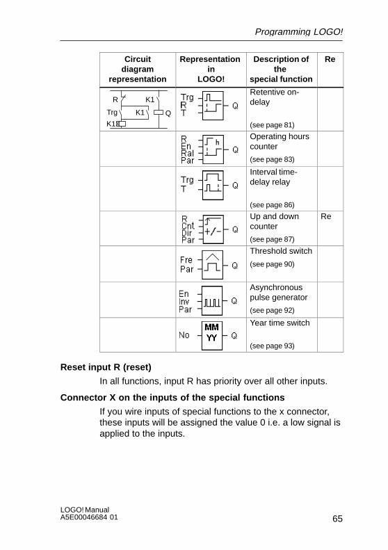
Circuitdiagram
representation
ReDescription ofthe
special function
Representation in
LOGO!
R K1
K1QTrg K1
Retentive on-delay
(see page 81)
Operating hourscounter
(see page 83)
Interval time-delay relay
(see page 86)
Up and downcounter
(see page 87)
Re
Threshold switch
(see page 90)
Asynchronouspulse generator
(see page 92)
Year time switch
(see page 93)
Reset input R (reset)
In all functions, input R has priority over all other inputs.
Connector X on the inputs of the special functions
If you wire inputs of special functions to the x connector,these inputs will be assigned the value 0 i.e. a low signal isapplied to the inputs.
Programming LOGO!

LOGO! ManualA5E00046684 01
66
Type of protection:
The parameter protection setting allows you to specifywhether the parameters can be displayed and altered inparameter assignment mode on the LOGO! module. Thereare two possible settings:
+: The parameter settings are also displayed in parameterassignment mode and can be changed.–: The parametersettings are not displayed in parameter assignment modeand can only be changed in programming mode.
Programming LOGO!
67LOGO! ManualA5E00046684 01
3.10.4 On-delay
Brief description
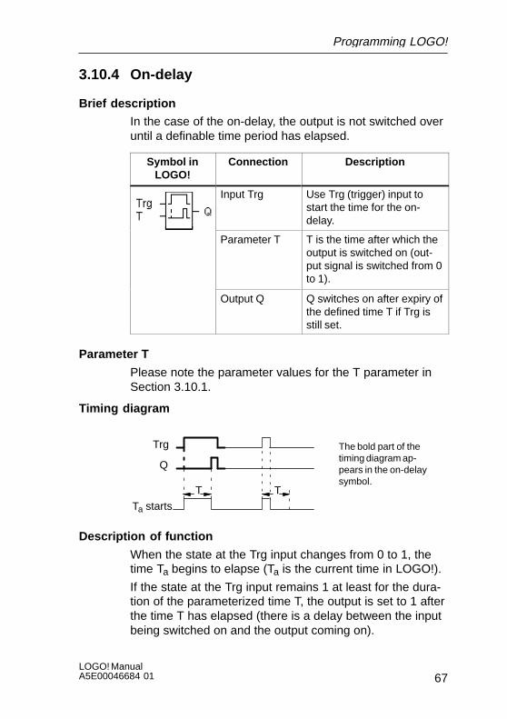
In the case of the on-delay, the output is not switched overuntil a definable time period has elapsed.
Symbol inLOGO!
Connection Description
Input Trg Use Trg (trigger) input tostart the time for the on-delay.
Parameter T T is the time after which theoutput is switched on (out-put signal is switched from 0to 1).
Output Q Q switches on after expiry ofthe defined time T if Trg isstill set.
Parameter T
Please note the parameter values for the T parameter inSection 3.10.1.
Timing diagram
Trg
T T
Ta starts
Q
The bold part of thetiming diagram ap-pears in the on-delaysymbol.
Description of function
When the state at the Trg input changes from 0 to 1, thetime Ta begins to elapse (Ta is the current time in LOGO!).
If the state at the Trg input remains 1 at least for the dura-tion of the parameterized time T, the output is set to 1 afterthe time T has elapsed (there is a delay between the inputbeing switched on and the output coming on).
Programming LOGO!

LOGO! ManualA5E00046684 01
68
If the state at the Trg input switches back to 0 before thetime T has elapsed, the time is reset.
The output is reset to 0 if the state at the Trg input is 0.
In the event of a power failure, the elapsed time is reset.
Programming LOGO!
69LOGO! ManualA5E00046684 01
3.10.5 Off-delay
Brief description
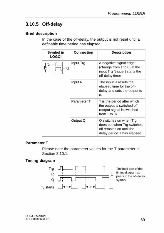
In the case of the off-delay, the output is not reset until adefinable time period has elapsed.
Symbol inLOGO!
Connection Description
Input Trg A negative signal edge(change from 1 to 0) at theinput Trg (trigger) starts theoff-delay timer
Input R The input R resets theelapsed time for the off-delay and sets the output to0.
Parameter T T is the period after whichthe output is switched off(output signal is switchedfrom 1 to 0).
Output Q Q switches on when Trgdoes but when Trg switchesoff remains on until thedelay period T has elapsed.
Parameter T
Please note the parameter values for the T parameter inSection 3.10.1.
Timing diagram
Trg
TTTa starts
Q
R
The bold part of thetiming diagram ap-pears in the off-delaysymbol.
Programming LOGO!

LOGO! ManualA5E00046684 01
70
Description of function
When the state at the input Trg changes to 1, the output Qswitches to 1 immediately.
When the state of Trg changes from 1 to 0, LOGO!’s cur-rent time Ta is started and the output remains set. If Tareaches the values specified via T (Ta=T), the output Q isreset to 0 (off-delay).
If the Trg input switches on and off again, the time Ta startsagain.
The input R (Reset) resets the elapsed time Ta and the out-put before the set time delay Ta has elapsed.
In the event of a power failure, the elapsed time is reset.
Programming LOGO!
71LOGO! ManualA5E00046684 01
3.10.6 Current impulse relay
Brief description
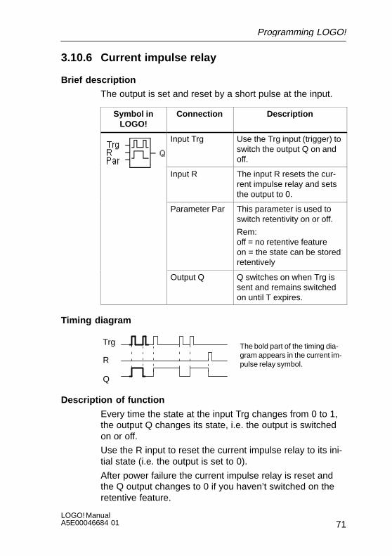
The output is set and reset by a short pulse at the input.
Symbol inLOGO!
Connection Description
Input Trg Use the Trg input (trigger) toswitch the output Q on andoff.
Input R The input R resets the cur-rent impulse relay and setsthe output to 0.
Parameter Par This parameter is used toswitch retentivity on or off.
Rem: off = no retentive featureon = the state can be storedretentively
Output Q Q switches on when Trg issent and remains switchedon until T expires.
Timing diagram
Trg
Q
R
The bold part of the timing dia-gram appears in the current im-pulse relay symbol.
Description of function
Every time the state at the input Trg changes from 0 to 1,the output Q changes its state, i.e. the output is switchedon or off.
Use the R input to reset the current impulse relay to its ini-tial state (i.e. the output is set to 0).
After power failure the current impulse relay is reset andthe Q output changes to 0 if you haven’t switched on theretentive feature.
Programming LOGO!
LOGO! ManualA5E00046684 01
72
3.10.7 Time switch
Brief description
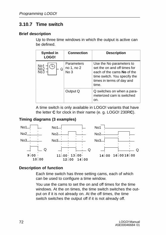
Up to three time windows in which the output is active canbe defined.
Symbol inLOGO!
Connection Description
Parametersno 1, no 2No 3
Use the No parameters toset the on and off times foreach of the cams No of thetime switch. You specify thetimes in terms of day andtime.
Output Q Q switches on when a para-meterized cam is switchedon.
A time switch is only available in LOGO! variants that havethe letter C for clock in their name (e. g. LOGO! 230RC).
Timing diagrams (3 examples)
No1
No2
No3
10:0011:009:00
14:0012:0013:00
Q
14:00 16:00 18:00
No1
No2
No3
No1
No2
No3
Description of function
Each time switch has three setting cams, each of whichcan be used to configure a time window.
You use the cams to set the on and off times for the timewindows. At the on times, the time switch switches the out-put on if it is not already on. At the off times, the timeswitch switches the output off if it is not already off.
Programming LOGO!
73LOGO! ManualA5E00046684 01
If you set an on time on one cam that is the same as theoff time on another cam on the time switch, then the onand off times conflict. In such cases, cam 3 has priorityover cam 2 and cam 2 has priority over cam 1.
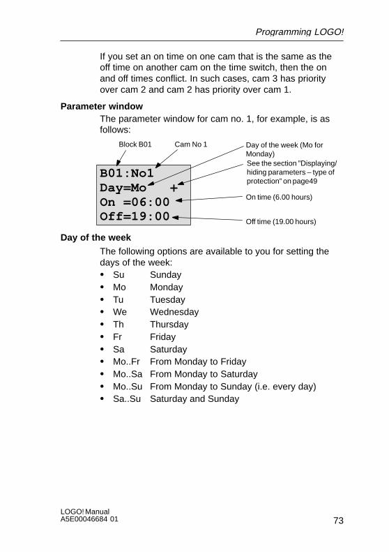
Parameter window The parameter window for cam no. 1, for example, is asfollows:
B01:No1Day=Mo +On =06:00Off=19:00
Day of the week (Mo forMonday)
On time (6.00 hours)
See the section ”Displaying/hiding parameters – type ofprotection” on page49
Off time (19.00 hours)
Block B01 Cam No 1
Day of the week
The following options are available to you for setting thedays of the week:S Su SundayS Mo MondayS Tu TuesdayS We WednesdayS Th ThursdayS Fr FridayS Sa SaturdayS Mo..Fr From Monday to FridayS Mo..Sa From Monday to SaturdayS Mo..Su From Monday to Sunday (i.e. every day)S Sa..Su Saturday and Sunday
Programming LOGO!

LOGO! ManualA5E00046684 01
74
Switching times
Any time between 00:00 and 23:59 hours––:–– means there is no on time
Any time between 00:00 and 23:59 hours––:–– means there is no off time
Setting the time switch
To enter the switching times, proceed as follows:
1. Position the cursor on one of the time switch’s No pa-rameters (e. g. No1).
2. Press OK. LOGO! opens the parameter window for thecam. The cursor is positioned on the day of the week.
3. Use the and keys to select one or more days of theweek.
4. Use the key to move the cursor to the first position forthe on time.
5. Set the on time.Use the and keys to change the value. To move thecursor from one position to another, use the and keys. You can only select the value ––:–– (––:–– means no switching operation).
6. Use the key to move the cursor to the first position forthe off time.
7. Set the off time (same procedure as for step 5).8. Conclude your input by pressing OK.
The cursor is positioned at parameter No 2 (cam 2).You can now parameterize another cam (as describedunder points 2. to 8.).
Note
Please refer to the technical specifications in Sec-tion 3.10.1 for information regarding the accuracy of thetime switch.
Programming LOGO!

75LOGO! ManualA5E00046684 01
Clock: examples
You can use the time switch to combine on and off timeshowever you like.
Here are some examples:
Example 1
The time switch’s output is to be switched on every day(i.e. from Monday to Sunday) from 08:00 to 13:00.
B01:No1Day= Mo..SuOn =08:00Off=13:00
On
Off8:00 13:00
Example 2
The time switch’s output is to be switched on every dayfrom 08:00 to 13:00 and from 15:00 to 18:30. You need 2cams for this:
B01:No1Day= Mo..SuOn =08:00Off=13:00
B01:No2Day= Mo..SuOn =15:00Off=18:30
On
Off8:00
13:0015:00
18:30
Example 3
The time switch’s output is to be switched on every dayfrom Monday to Saturday from 08:00 to 13:00 and from15:00 to 18:30. It is also to be switched on between thehours of 11:00 and 15:00 on Sundays. You need 3 camsfor this:
B01:No1Day= Mo..SaOn =08:00Off=13:00
B01:No2Day= Mo..SaOn =15:00Off=18:30
B01:No3Day= SuOn =11:00Off=15:00
Mo...Sa
8:0013:00
15:0018:30
Su
11:00 15:00
Off
On
Off
On
Programming LOGO!

LOGO! ManualA5E00046684 01
76
Example 4
The time switch’s output is to be switched on on Monday at22:00 hours and of on Tuesday at 6:00 hours.
B01:No1Day= MoOn =22:00Off=––:––
B01:No2Day= TuOn =––:––Off=06:00Mo
22:00Tu06:00
Programming LOGO!
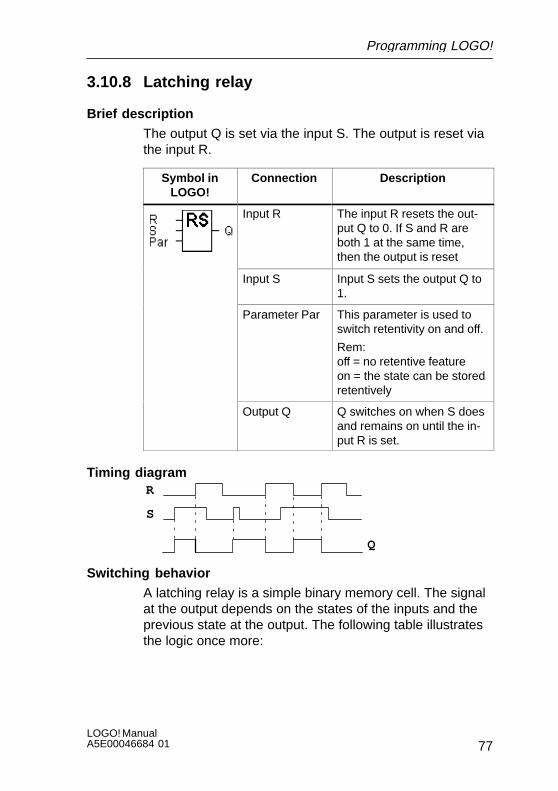
77LOGO! ManualA5E00046684 01
3.10.8 Latching relay
Brief description
The output Q is set via the input S. The output is reset viathe input R.
Symbol inLOGO!
Connection Description
Input R The input R resets the out-put Q to 0. If S and R areboth 1 at the same time,then the output is reset
Input S Input S sets the output Q to1.
Parameter Par This parameter is used toswitch retentivity on and off.
Rem: off = no retentive featureon = the state can be storedretentively
Output Q Q switches on when S doesand remains on until the in-put R is set.
Timing diagram
S
R
Q
Switching behavior
A latching relay is a simple binary memory cell. The signalat the output depends on the states of the inputs and theprevious state at the output. The following table illustratesthe logic once more:
Programming LOGO!

LOGO! ManualA5E00046684 01
78
Sn Rn Q Remarks
0 0 x State remains the same0 1 0 Reset1 0 1 Set1 1 0 Reset (resetting has priority over setting)
After power failure the signal that was valid before thepower failure is set at the output if the retentive feature wasswitched on.
Programming LOGO!

79LOGO! ManualA5E00046684 01
3.10.9 Symmetrical clock pulse generator
Brief description
A clock pulse with a definable period length is output at theoutput.
Symbol inLOGO!
Connection Description
Input En The En input switches theclock pulse generator onand off.
Parameter T T is the time for which theoutput is switched on or off.
Output Q Q switches on and off cycli-cally in time with the pulseperiod T.
Parameter T
Please refer to the note in Section 3.10.1 when specifyingthe values.
Timing diagram
En
Q T TT T
The bold part of the timing diagram appears in the symmetricalclock pulse generator symbol.
Description of function
The parameter T specifies the length of the on and off peri-ods. Use the En (enable) input to switch the clock pulsegenerator on. The pulse generator sets the output to 1 forthe time T, then to 0 for the time T and so on until the Eninput is a 0.
Programming LOGO!

LOGO! ManualA5E00046684 01
80
Note on the relay ouputs:
Relay outputs that switch under load get worn a little witheach switching operation. To find out how many switchingoperations a LOGO! output can execute, refer to the Chap-ter entitled Technical Specifications (see Chapter A).
Programming LOGO!
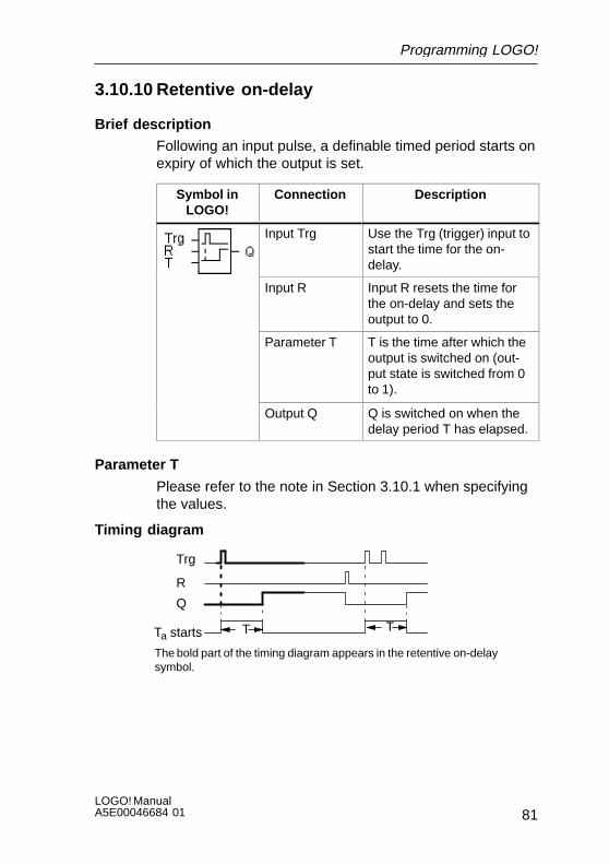
81LOGO! ManualA5E00046684 01
3.10.10 Retentive on-delay
Brief description
Following an input pulse, a definable timed period starts onexpiry of which the output is set.
Symbol inLOGO!
Connection Description
Input Trg Use the Trg (trigger) input tostart the time for the on-delay.
Input R Input R resets the time forthe on-delay and sets theoutput to 0.
Parameter T T is the time after which theoutput is switched on (out-put state is switched from 0to 1).
Output Q Q is switched on when thedelay period T has elapsed.
Parameter T
Please refer to the note in Section 3.10.1 when specifyingthe values.
Timing diagram
Trg
TTa starts
Q
R
T
The bold part of the timing diagram appears in the retentive on-delaysymbol.
Programming LOGO!

LOGO! ManualA5E00046684 01
82
Description of function
When the state at the Trg input changes from 0 to 1, thecurrent time Ta starts. When Ta reaches the time T, outputQ is set to 1. Another switching operation at the Trg inputhas no effect on Ta.
The output and the time Ta are not reset to 0, until the stateof the R input changes to 1 again.
In the event of a power failure, the elapsed time is reset.
Programming LOGO!
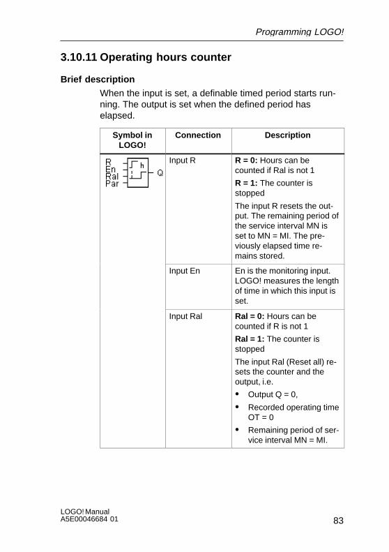
83LOGO! ManualA5E00046684 01
3.10.11 Operating hours counter
Brief description
When the input is set, a definable timed period starts run-ning. The output is set when the defined period haselapsed.
Symbol inLOGO!
Connection Description
Input R R = 0: Hours can becounted if Ral is not 1
R = 1: The counter isstopped
The input R resets the out-put. The remaining period ofthe service interval MN isset to MN = MI. The pre-viously elapsed time re-mains stored.
Input En En is the monitoring input.LOGO! measures the lengthof time in which this input isset.
Input Ral Ral = 0: Hours can becounted if R is not 1
Ral = 1: The counter isstopped
The input Ral (Reset all) re-sets the counter and theoutput, i.e.
S Output Q = 0,
S Recorded operating timeOT = 0
S Remaining period of ser-vice interval MN = MI.
Programming LOGO!
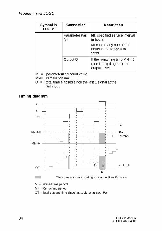
LOGO! ManualA5E00046684 01
84
Symbol inLOGO!
DescriptionConnection
Parameter Par:MI
MI: specified service intervalin hours.
MI can be any number ofhours in the range 0 to9999.
Output Q If the remaining time MN = 0(see timing diagram), theoutput is set.
MI = parameterized count valueMN= remaining timeOT= total time elapsed since the last 1 signal at the
Ral input
Timing diagram
MI = Defined time periodMN = Remaining periodOT = Total elapsed time since last 1 signal at input Ral
Par:
Q
R
Ral
En
MN=MI
OT
MN=0
The counter stops counting as long as R or Ral is set
MI=5h
1h x–R=1h
R
x
Programming LOGO!
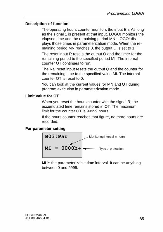
85LOGO! ManualA5E00046684 01
Description of function
The operating hours counter monitors the input En. As longas the signal 1 is present at that input, LOGO! monitors theelapsed time and the remaining period MN. LOGO! dis-plays those times in parameterization mode. When the re-maining period MN reaches 0, the output Q is set to 1.
The reset input R resets the output Q and the timer for theremaining period to the specified period MI. The internalcounter OT continues to run.
The Ral reset input resets the output Q and the counter forthe remaining time to the specified value MI. The internalcounter OT is reset to 0.
You can look at the current values for MN and OT duringprogram execution in parameterization mode.
Limit value for OT
When you reset the hours counter with the signal R, theaccumulated time remains stored in OT. The maximumlimit for the counter OT is 99999 hours.
If the hours counter reaches that figure, no more hours arerecorded.
Par parameter setting
B03:Par
MI = 0000h+
Monitoring interval in hours
Type of protection
MI is the parameterizable time interval. It can be anythingbetween 0 and 9999.
Programming LOGO!

LOGO! ManualA5E00046684 01
86
3.10.12 Interval time-delay relay – pulse output
Brief description
An input signal produces a signal of definable duration atthe output.
Symbol inLOGO!
Connection Description
Input Trg The input Trg (trigger) startsthe time for the interval time-delay relay.
Parameter T T is the period after whichthe output is switched off(output signal is switchedfrom 1 to 0).
Output Q Q switches on when Trgdoes but when Trg switchesoff remains on until thedelay period T has elapsed.
Parameter T
Please refer to the note on the T parameter in Sec-tion 3.10.1.
Timing diagram
Trg
T has not expired completelyTa starts
Q
The bold part of the timing diagramappears in the interval time-delayrelay symbol.
T
Description of function
When the input Trg switches to the state 1, the output Qimmediately switches to the state 1. At the same time, theelapsed time Ta starts running; the output remains set. If Tareaches the time specified for T (Ta=T), the output Q is re-set to 0 (pulse output).
If the state at the input Trg switches back from 1 to 0 be-fore the specified time has elapsed, the output also imme-diately switches back from 1 to 0.
Programming LOGO!
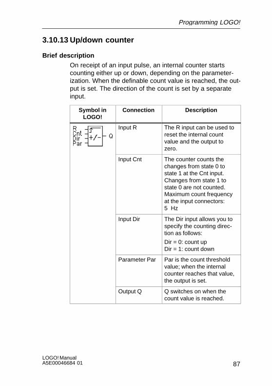
87LOGO! ManualA5E00046684 01
3.10.13 Up/down counter
Brief description
On receipt of an input pulse, an internal counter startscounting either up or down, depending on the parameter-ization. When the definable count value is reached, the out-put is set. The direction of the count is set by a separateinput.
Symbol inLOGO!
Connection Description
Input R The R input can be used toreset the internal countvalue and the output tozero.
Input Cnt The counter counts thechanges from state 0 tostate 1 at the Cnt input.Changes from state 1 tostate 0 are not counted.Maximum count frequencyat the input connectors:5 Hz
Input Dir The Dir input allows you tospecify the counting direc-tion as follows:
Dir = 0: count upDir = 1: count down
Parameter Par Par is the count thresholdvalue; when the internalcounter reaches that value,the output is set.
Output Q Q switches on when thecount value is reached.
Programming LOGO!

LOGO! ManualA5E00046684 01
88
Timing diagram
R
Dir
Par
Cnt
0
Q
Internalcount valueCnt
Description of function
At each positive signal edge at the input, Cnt either in-creases the internal counter value by one (Dir = 0) or de-creases it by one (Dir = 1).
If the internal counter value is greater than or equal to thevalue specified for Par, the output Q is set to 1.
The Reset input R can be used to reset the internal countervalue and the output to ’000000’. As long as R=1, the out-put remains set to 0 and the pulses at the input Cnt are notcounted.
Par parameter setting
B03:Par
Rem=off
Par= 000100h+
Count value
Retentivity
See the parameter for display-ing/hiding – type of protectionon page 49
If the internal counter value is greater than or equal to Par,output Q is set. The counter remains the same in the caseof under or overflow.
Par can be anything between 0 and 999999.
Rem: This parameter switches the retentive feature of theinternal Cnt counter on an off.
off = No retentive featureon = The Cnt counter can be stored retentively
Programming LOGO!

89LOGO! ManualA5E00046684 01
If the retentive feature is switched on, when a power failureoccurs the counter status remains the same and this valueis used once power is restored.
Programming LOGO!
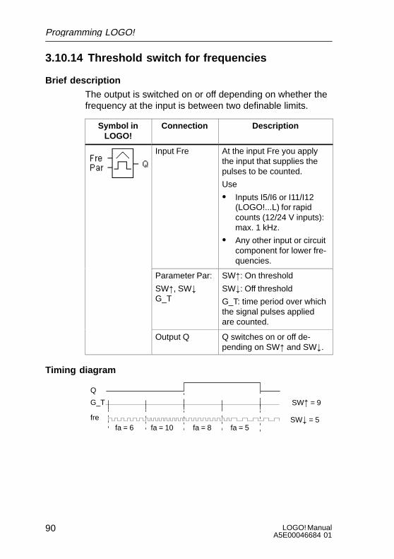
LOGO! ManualA5E00046684 01
90
3.10.14 Threshold switch for frequencies
Brief description
The output is switched on or off depending on whether thefrequency at the input is between two definable limits.
Symbol inLOGO!
Connection Description
Input Fre At the input Fre you applythe input that supplies thepulses to be counted.
Use
S Inputs I5/I6 or I11/I12(LOGO!...L) for rapidcounts (12/24 V inputs):max. 1 kHz.
S Any other input or circuitcomponent for lower fre-quencies.
Parameter Par:
SW", SW#G_T
SW": On threshold
SW#: Off threshold
G_T: time period over whichthe signal pulses appliedare counted.
Output Q Q switches on or off de-pending on SW" and SW#.
Timing diagram
Q
SW" = 9
SW# = 5fa = 6 fa = 10 fa = 8 fa = 5
G_T
fre
Programming LOGO!
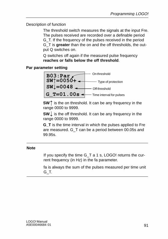
91LOGO! ManualA5E00046684 01
Description of function
The threshold switch measures the signals at the input Fre.The pulses received are recorded over a definable periodG_T. If the frequency of the pulses received in the periodG_T is greater than the on and the off thresholds, the out-put Q switches on.
Q switches off again if the measured pulse frequencyreaches or falls below the off threshold .
Par parameter setting
B03:Par
G_T=01.00s
On threshold
Type of protection
Time interval for pulses
Off threshold
SW"=0050+SW#=0048
SW" is the on threshold. It can be any frequency in therange 0000 to 9999.
SW# is the off threshold. It can be any frequency in therange 0000 to 9999.
G_T is the time interval in which the pulses applied to Freare measured. G_T can be a period between 00.05s and99.95s.
Note
If you specify the time G_T a 1 s, LOGO! returns the cur-rent frequency (in Hz) in the fa parameter.
fa is always the sum of the pulses measured per time unitG_T.
Programming LOGO!
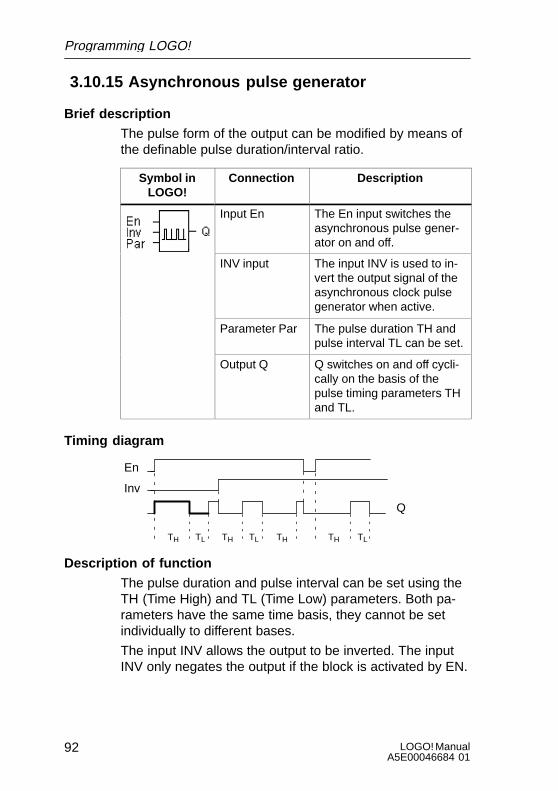
LOGO! ManualA5E00046684 01
92
3.10.15 Asynchronous pulse generator
Brief description
The pulse form of the output can be modified by means ofthe definable pulse duration/interval ratio.
Symbol inLOGO!
Connection Description
Input En The En input switches theasynchronous pulse gener-ator on and off.
INV input The input INV is used to in-vert the output signal of theasynchronous clock pulsegenerator when active.
Parameter Par The pulse duration TH andpulse interval TL can be set.
Output Q Q switches on and off cycli-cally on the basis of thepulse timing parameters THand TL.
Timing diagram
En
Inv
TH
Q
TL THTL TH TLTH
Description of function
The pulse duration and pulse interval can be set using theTH (Time High) and TL (Time Low) parameters. Both pa-rameters have the same time basis, they cannot be setindividually to different bases.
The input INV allows the output to be inverted. The inputINV only negates the output if the block is activated by EN.
Programming LOGO!

93LOGO! ManualA5E00046684 01
3.10.16 Twelve-month time switch
Brief description
The output is controlled by a definable on/off date.
Symbol inLOGO!
Connection Description
Input No Use the No parameter to setthe on and off times for thecam of the twelve-monthtime switch.
Output Q Q switches on when theparameterizable cam isswitched on.
Timing diagram
MM.DD+On=02.20Off=04.03
OnOff
20 February 3 April
feb. mar. apr.
Description of function
At the on time, the year time switch switches the output onand at the off time, it switches the output off. The off dateindicates the date on which the output is reset to 0. Thefirst value indicates the month, the second value indicatesthe day.
The LOGO! module is not susceptible to year-2000 prob-lems.
Programming LOGO!

LOGO! ManualA5E00046684 01
94
Parameterization example
The output of a LOGO! has to be switched on every yearon 1 March and switched off on 4 April, switched on againon 7 July and switched off on 19 November. For this yourequire 2 twelve-month time switches each of which is con-figured for one of the on periods. The outputs are thenlinked by an OR block.
B01:No MM.DDOn=03.01Off=04.04
B02:No MM.DDOn=07.07Off=11.19
On
Off
1 March
4 April
7 July
19 November
B01 B02
Clock backup
The internal clock of a LOGO! module continues to run ifthere is a power failure, i.e. it has a power buffer. The dura-tion of the reserve power is affected by the ambient tem-perature. At an ambient temperature of 25°C the typicalpower buffer is 80 hours.
Programming LOGO!

95LOGO! ManualA5E00046684 01
3.11 Memory required and size of a circuit
A program (control program in LOGO!, circuit diagram) hasthe following limitations:S The number of blocks connected in series (nesting
depth)S The memory space (use of memory by the blocks)
Memory area
You can use a certain number of blocks for your program inLOGO!. In addition, some blocks require extra memory fortheir special functions.
The memory required for special functions is divided upinto 4 memory areas.S Par: The area in which LOGO! stores the desired val-
ues (e.g. the limit values of a counter).S RAM: The area in which LOGO! stores the current ac-
tual values (e.g. the counter status).S Timer: The area LOGO! uses for time functions such as
the off-delay.S REM: The area in which LOGO! stores actual values
that have to be retained (e.g. the count value of an op-erating hours counter). In blocks with selective use ofthe retentive feature, this memory area is only used ifthe retentive feature is switched on.
Resources available in LOGO!
The maximum amount of resources that can be occupiedby a program in LOGO! is as follows:
Blocks Par RAM Timer REM Bit
56 48 27 16 15 4
LOGO! monitors memory utilization, and offers in the func-tion lists only those functions for which there is still actuallyenough memory space available.
Programming LOGO!
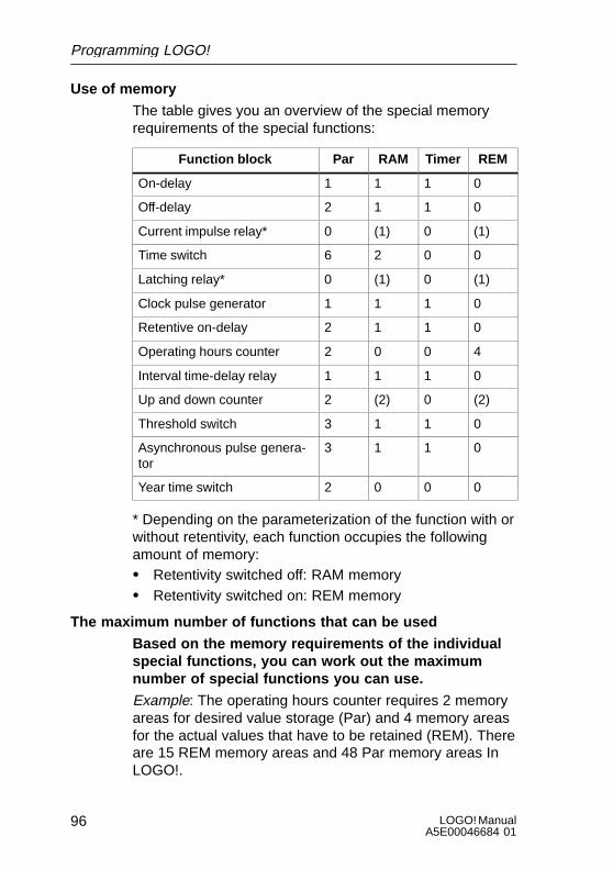
LOGO! ManualA5E00046684 01
96
Use of memory
The table gives you an overview of the special memoryrequirements of the special functions:
Function block Par RAM Timer REM
On-delay 1 1 1 0
Off-delay 2 1 1 0
Current impulse relay* 0 (1) 0 (1)
Time switch 6 2 0 0
Latching relay* 0 (1) 0 (1)
Clock pulse generator 1 1 1 0
Retentive on-delay 2 1 1 0
Operating hours counter 2 0 0 4
Interval time-delay relay 1 1 1 0
Up and down counter 2 (2) 0 (2)
Threshold switch 3 1 1 0
Asynchronous pulse genera-tor
3 1 1 0
Year time switch 2 0 0 0
* Depending on the parameterization of the function with orwithout retentivity, each function occupies the followingamount of memory:S Retentivity switched off: RAM memoryS Retentivity switched on: REM memory
The maximum number of functions that can be used
Based on the memory requirements of the individualspecial functions, you can work out the maximumnumber of special functions you can use.
Example: The operating hours counter requires 2 memoryareas for desired value storage (Par) and 4 memory areasfor the actual values that have to be retained (REM). Thereare 15 REM memory areas and 48 Par memory areas InLOGO!.
Programming LOGO!

97LOGO! ManualA5E00046684 01
The special function of the operating hours counter cantherefore only be used a maximum of 3 times, leaving just3 REM memory areas left. Although there are still 42 Parmemory areas free, you are one REM memory area shortto run an additional operating hours counter.
Calculation: Free memory areas divided by the requirednumber of memory areas. Carry out this calculation foreach memory area required (Par, RAM, timer, REM). Thelowest value shows you the maximum number of functionsyou can use.
Nesting depth
In LOGO! there is a maximum nesting depth that canbe implemented in your program. The maximum nest-ing depth in a program path is 9 blocks.
A program path consists of a series of function blocksstarting and ending with a terminal block. The number ofblocks in a program path describes the nesting depth.
Inputs and levels (I, Ia, hi, lo), as well as outputs and mark-ers (Q, Qa, M) are terminal blocks . The terminal blocksare not represented by a block symbol in LOGO!.
Calculating the nesting depth
If you deduct the two terminal blocks from the maximumnesting depth of 9 blocks, you are left with 7 functionblocks, which you can connect in series in a circuit.
Q1x
I1
I2
I4
I5x
I6
I1
I3
B1
B2
B3B4B5B6B7
B8
B9
B10
Max. 7 function blocks
Programming LOGO!

LOGO! ManualA5E00046684 01
98
Implementing longer program paths
Longer program paths can be implemented using markers.This is done by placing a marker block at the end of a path.The remaining function blocks are connected to the outputof the marker. LOGO! interprets the marker as the outputof the first program path (markers are terminal blocks) andalso as the input of the next program path. They representtwo individual paths to LOGO!.
If another marker block is not available, you can use anoutput block instead.
Programming LOGO!

99LOGO! ManualA5E00046684 01
4 Parameterizing LOGO!By parameterization we mean setting the parameters of theblocks. You can set delay times for time functions, switch-ing times for time switches, the threshold value of acounter, the monitoring interval of an operating hourscounter and the on and off thresholds of the thresholdswitch.
You can set the parameters:S In programming modeS In parameterization mode
In parameterization mode the programmer sets a value fora parameter.We introduced parameterization mode so that parameterscan be changed without having to change the program. Inthis way, a user can change the times without having tochange into programming mode. The advantage of this isthat the program (and thus the circuit) is protected but canstill be modified by the user of the circuit to suit require-ments.
Note
LOGO! continues to execute the program in parameteriza-tion mode.
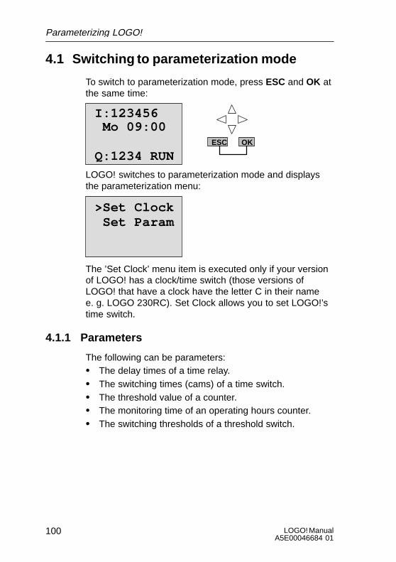
LOGO! ManualA5E00046684 01
100
4.1 Switching to parameterization mode
To switch to parameterization mode, press ESC and OK atthe same time:
I:123456
Q:1234 RUN
Mo 09:00ESC OK
LOGO! switches to parameterization mode and displaysthe parameterization menu:
>Set Clock Set Param
The ’Set Clock’ menu item is executed only if your versionof LOGO! has a clock/time switch (those versions ofLOGO! that have a clock have the letter C in their name e. g. LOGO 230RC). Set Clock allows you to set LOGO!’stime switch.
4.1.1 Parameters
The following can be parameters:S The delay times of a time relay.S The switching times (cams) of a time switch.S The threshold value of a counter.S The monitoring time of an operating hours counter.S The switching thresholds of a threshold switch.
Parameterizing LOGO!

101LOGO! ManualA5E00046684 01
Each parameter is identified by the block number and theparameter abbreviation. Examples:
B01:T
Block number Parameter abbreviation
S T: ...is a time that can be set.S No1: ...is the first cam of a time switch (clock).S Par: ...refers to several counters that can be monitored.
4.1.2 Selecting a parameter
To select a parameter, proceed as follows:1. Select the ’Set Param’ option from the parameterization
menu.
Set Clock>Set Param
2. Press OK
LOGO! displays the first parameter:
B01:T
Ta = 00:00m
T = 12:00mParameter
Value set for the parameter
Current time in LOGO!
Parameterizing LOGO!

LOGO! ManualA5E00046684 01
102
If no parameter can be set, LOGO! displays the following:
Press ESCNo Param
No parameter can be changed:ESC returns you to the parameterization menu
3. Select the desired parameter: or
LOGO! displays a parameter in a separate window.4. To change a parameter, select it and press OK.
4.1.3 Changing a parameter
To change a parameter, you first have to select it (see ”Se-lecting a parameter).
You change the value of the parameter in the same way asyou entered it in programming mode:1. Move the cursor to the point at which you want to make
the change: or
2. Change the value: or
3. Accept the value:OK
B01:T
Ta = 00:00m
Move: A or "
Change the value: Y or BFinished: OK
T = 01:00m
You cannot change the unit of the delay time for the param-eter T in parameterization mode. This is only possible inprogramming mode.
Parameterizing LOGO!

103LOGO! ManualA5E00046684 01
Current value of a time T
If you view a time T in parameterization mode, it looks likethis:
B01:T
Ta = 00:00m
T = 12:00m Time T set
Current time Ta
You can change the set time T (see ”Changing a parame-ter”).
Current value of the time switch
If you view a cam of a time switch in parameterizationmode, it looks like this, for example:
The time switch is off(state ’0’ at the output)
The time switch is on(state ’1’ at the output)
B02:No1
Off=10:00
Day = Su
The circuit state of the time switch is displayed:
On =09:00
1
1
0
LOGO! displays the circuit state of the time switch ratherthan the circuit state of a cam. The circuit state of the timeswitch depends on all three cams (No1, No 2 and No 3).
Parameterizing LOGO!
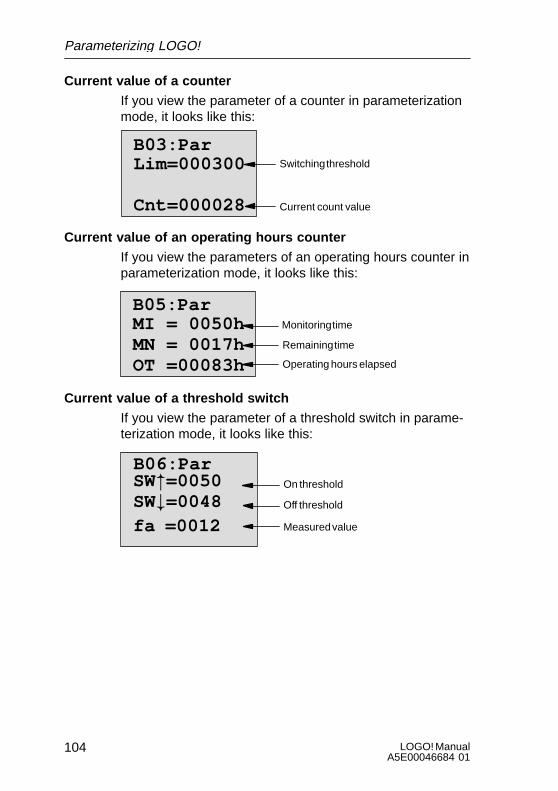
LOGO! ManualA5E00046684 01
104
Current value of a counter
If you view the parameter of a counter in parameterizationmode, it looks like this:
Cnt=000028
Lim=000300B03:Par
Switching threshold
Current count value
Current value of an operating hours counter
If you view the parameters of an operating hours counter inparameterization mode, it looks like this:
B05:ParMI = 0050hMN = 0017hOT =00083h
Remaining time
Operating hours elapsed
Monitoring time
Current value of a threshold switch
If you view the parameter of a threshold switch in parame-terization mode, it looks like this:
B06:Par
Off threshold
Measured value
On thresholdSW"=0050SW#=0048fa =0012
Parameterizing LOGO!
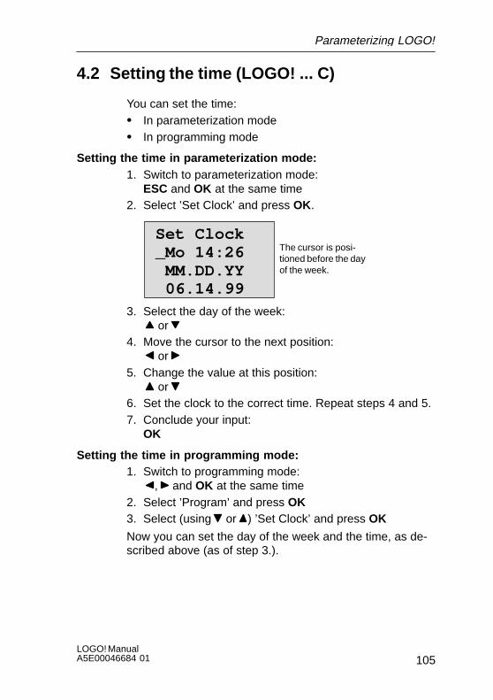
105LOGO! ManualA5E00046684 01
4.2 Setting the time (LOGO! ... C)
You can set the time:S In parameterization modeS In programming mode
Setting the time in parameterization mode:1. Switch to parameterization mode:
ESC and OK at the same time2. Select ’Set Clock’ and press OK.
Set Clock_Mo 14:26 MM.DD.YY 06.14.99
The cursor is posi-tioned before the dayof the week.
3. Select the day of the week: or
4. Move the cursor to the next position: or
5. Change the value at this position: or
6. Set the clock to the correct time. Repeat steps 4 and 5.7. Conclude your input:
OK
Setting the time in programming mode:1. Switch to programming mode:
, and OK at the same time2. Select ’Program’ and press OK3. Select (using or ) ’Set Clock’ and press OK
Now you can set the day of the week and the time, as de-scribed above (as of step 3.).
Parameterizing LOGO!
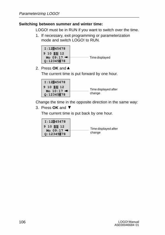
LOGO! ManualA5E00046684 01
106
Switching between summer and winter time:
LOGO! must be in RUN if you want to switch over the time.1. If necessary, exit programming or parameterization
mode and switch LOGO! to RUN.
Time displayed Mo 09:17
I:12345678
9 10 11 12
Q:12345678
2. Press OK and The current time is put forward by one hour.
Time displayed afterchange
Mo 10:17
I:12345678
9 10 11 12
Q:12345678
Change the time in the opposite direction in the same way:3. Press OK and
The current time is put back by one hour.
Time displayed afterchange
Mo 09:17
I:12345678
9 10 11 12
Q:12345678
Parameterizing LOGO!
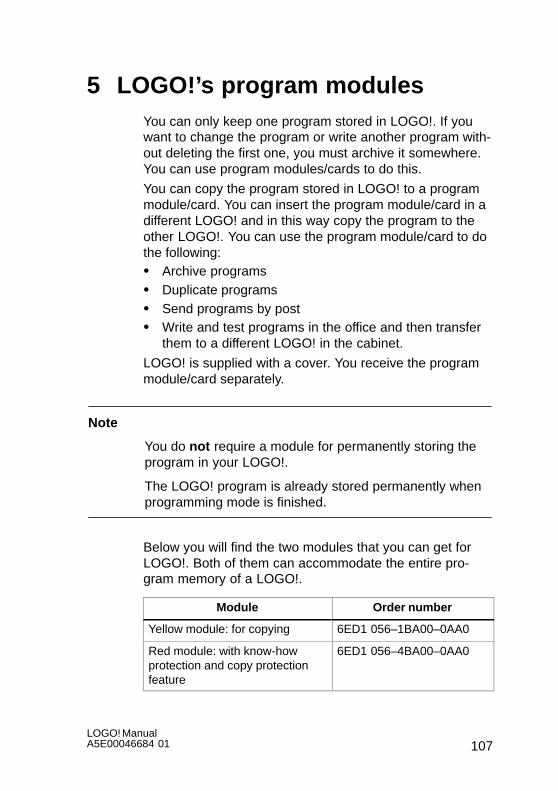
107LOGO! ManualA5E00046684 01
5 LOGO!’s program modulesYou can only keep one program stored in LOGO!. If youwant to change the program or write another program with-out deleting the first one, you must archive it somewhere.You can use program modules/cards to do this.
You can copy the program stored in LOGO! to a programmodule/card. You can insert the program module/card in adifferent LOGO! and in this way copy the program to theother LOGO!. You can use the program module/card to dothe following:S Archive programsS Duplicate programsS Send programs by postS Write and test programs in the office and then transfer
them to a different LOGO! in the cabinet.
LOGO! is supplied with a cover. You receive the programmodule/card separately.
Note
You do not require a module for permanently storing theprogram in your LOGO!.
The LOGO! program is already stored permanently whenprogramming mode is finished.
Below you will find the two modules that you can get forLOGO!. Both of them can accommodate the entire pro-gram memory of a LOGO!.
Module Order number
Yellow module: for copying 6ED1 056–1BA00–0AA0
Red module: with know-howprotection and copy protectionfeature
6ED1 056–4BA00–0AA0

LOGO! ManualA5E00046684 01
108
5.1 Overview of the modules
In this section we will describe the features of the two mod-ules.
Yellow program module
You can read and write programs with this module.
Red program module
You can only write programs with this module. Once a pro-gram has been stored, it cannot be looked at, copied orchanged (i.e. your data is protected).
Programs saved like this can only be run if the module re-mains inserted in LOGO! while the system is in operation.
! Warning
Make sure that you don’t save your program ona module with program protection if you intend toedit it further.
You can start up a program on a module withknow-how protection but not read it for the pur-pose of editing.
LOGO!’s program modules
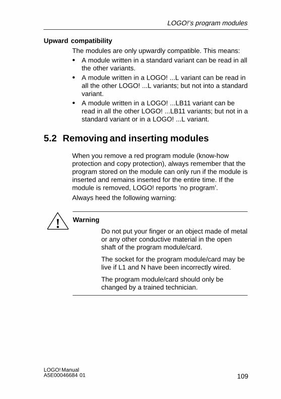
109LOGO! ManualA5E00046684 01
Upward compatibility
The modules are only upwardly compatible. This means:S A module written in a standard variant can be read in all
the other variants.S A module written in a LOGO! ...L variant can be read in
all the other LOGO! ...L variants; but not into a standardvariant.
S A module written in a LOGO! ...LB11 variant can beread in all the other LOGO! ...LB11 variants; but not in astandard variant or in a LOGO! ...L variant.
5.2 Removing and inserting modules
When you remove a red program module (know-howprotection and copy protection), always remember that theprogram stored on the module can only run if the module isinserted and remains inserted for the entire time. If themodule is removed, LOGO! reports ’no program’.
Always heed the following warning:
! Warning
Do not put your finger or an object made of metalor any other conductive material in the openshaft of the program module/card.
The socket for the program module/card may belive if L1 and N have been incorrectly wired.
The program module/card should only bechanged by a trained technician.
LOGO!’s program modules
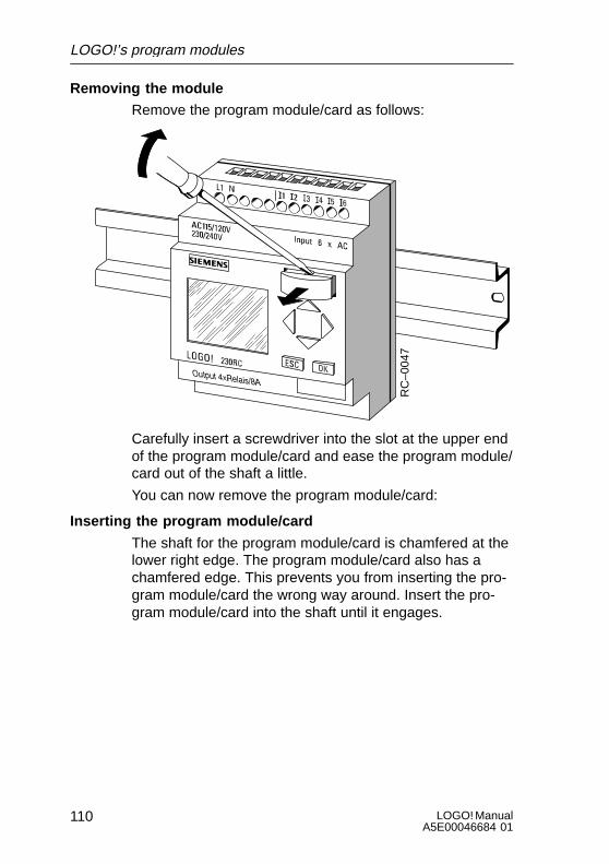
LOGO! ManualA5E00046684 01
110
Removing the module
Remove the program module/card as follows:
RC
–004
7
Carefully insert a screwdriver into the slot at the upper endof the program module/card and ease the program module/card out of the shaft a little.
You can now remove the program module/card:
Inserting the program module/card
The shaft for the program module/card is chamfered at thelower right edge. The program module/card also has achamfered edge. This prevents you from inserting the pro-gram module/card the wrong way around. Insert the pro-gram module/card into the shaft until it engages.
LOGO!’s program modules
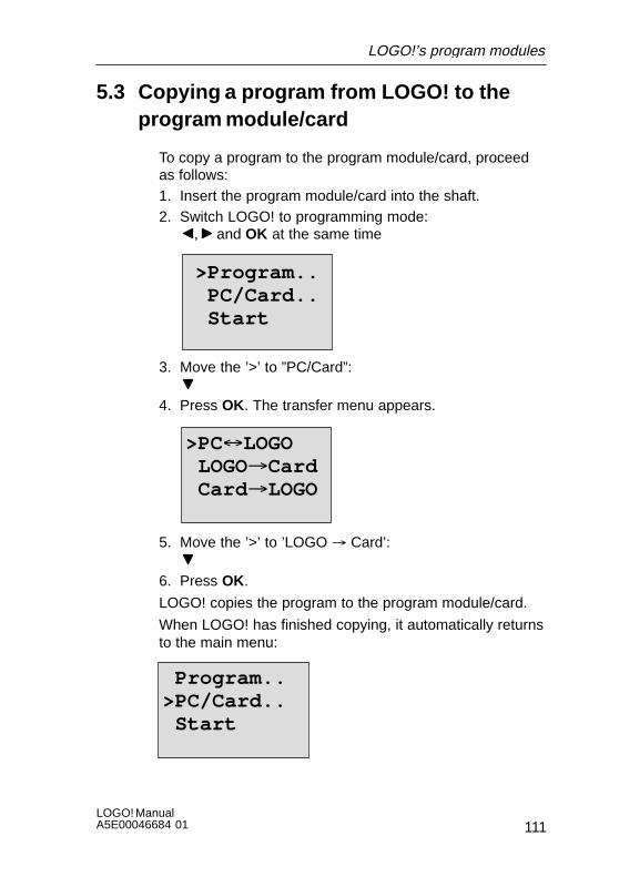
111LOGO! ManualA5E00046684 01
5.3 Copying a program from LOGO! to theprogram module/card
To copy a program to the program module/card, proceedas follows:1. Insert the program module/card into the shaft.2. Switch LOGO! to programming mode:
, and OK at the same time
>Program.. PC/Card.. Start
3. Move the ’>’ to ”PC/Card”:
4. Press OK. The transfer menu appears.
>PC LOGO LOGO³Card Card ³LOGO
5. Move the ’>’ to ’LOGO ³ Card’:
6. Press OK.
LOGO! copies the program to the program module/card.
When LOGO! has finished copying, it automatically returnsto the main menu:
Program..>PC/Card.. Start
LOGO!’s program modules

LOGO! ManualA5E00046684 01
112
The program is now also on the program module/card. Youcan now remove the program module/card. Don’t forget toreplace the cover.
If there is a power failure while LOGO! is copying, youhave to copy the program again once the power has beenrestored.
5.4 Copying a program from the programmodule/card to LOGO!
You have a program module/card containing your program.You can copy the program to LOGO! in two ways:S Automatically when LOGO! starts up (power on)S Via LOGO!’s PC/Card menu.
Note
Please note that not all programs stored on the modulescan be read in all LOGO! variants. If necessary, read Sec-tion 5.1 again.
Automatic copying when LOGO! starts up
Proceed as follows:1. Switch off the power supply to LOGO! (power down)2. Remove the cover shaft.3. Insert the program module/card into the appropriate
shaft.4. Switch on the power supply to LOGO! again.
LOGO!’s program modules

113LOGO! ManualA5E00046684 01
Result: LOGO! copies the program from the program mod-ule/card to LOGO!. As soon as LOGO! has finished copy-ing, LOGO! displays the main menu:
>Program.. PC/Card.. Start
Note
Before you switch LOGO! to RUN, you must ensure thatthe system you are controlling with LOGO! does not repre-sent a source of danger.
1. Move the ’>’ to Start:2
2. Press OK
Using the PC/Card menu to copy
Read the note about changing the program module/card.
To copy a program from the program module/card toLOGO!, proceed as follows:1. Insert the program module/card2. Switch LOGO! to programming mode:
, and OK at the same time
>Program.. PC/Card.. Start
3. Move the ’>’ to ”PC/Card”:
LOGO!’s program modules

LOGO! ManualA5E00046684 01
114
4. Press OK. The transfer menu appears.
PC´LOGO LOGO³Card>Card³LOGO
5. Move the ’>’ to ’Card ³ LOGO’: or 6. Press OK.
Result: LOGO! copies the program from the program mod-ule/card to LOGO!. As soon as LOGO! has finished copy-ing, LOGO! automatically displays the main menu:
LOGO!’s program modules

115LOGO! ManualA5E00046684 01
6 LOGO! softwareLOGO!Soft and LOGO!Soft Comfort are programmingpackages for use on PCs. The software has the followingfunctions:S Offline program generation of your applicationS Simulation of your circuit (or your program) on the com-
puterS Generation and printing of a block diagram of the circuitS Saving the program to the hard disk or another storage
mediumS Program transfer
– From LOGO! to the PC– From the PC to LOGO!
The LOGO! alternative
LOGO! software provides you with an alternative to con-ventional planning:1. First you develop your applications at your desk.2. You simulate the application in your computer and test
whether or not it functions properly before the circuit isactually put to use.
3. You print out the entire circuit in a block diagram or inseveral block diagrams sorted according to outputs.
4. You archive your circuits in your PC file system. In thisway you can retrieve a circuit directly if you want tomake changes some time in the future.
5. You transfer the program to LOGO! by pressing just afew buttons. Your LOGO! is retooled within a very shortspace of time.

LOGO! ManualA5E00046684 01
116
LOGO!Soft
After program startup, select the LOGO! variant you areworking with. This LOGO! variant is displayed on thescreen. Using the mouse you can program LOGO! fromyour desk in the same way you might otherwise have donedirectly on the system.
LOGO!Soft helps you to create and edit control programson the PC. The optional 8-language programming softwareunder Windows allows you to create, test and simulate,change, archive and print control programs using your PC.
LOGO!Soft Comfort
LOGO!Soft Comfort makes creating control programs eas-ier, more efficient and more manageable than in the past.Programs are created on the PC using the drag-and-droptechnique. You first write the program and then assesswhich LOGO! variants are required for the completed pro-gram.
One particularly user-friendly feature is the offline programsimulation facility, which enables the simultaneous statusdisplay of multiple special functions and permits extensivedocumentation of the programs created. This optional pro-gram software also provides a comprehensive online helpsystem on CD ROM .
The 6-language LOGO!Soft Comfort software runs as ofWindows 95, is server-capable and offers you extensivefreedom and maximum ease in creating programs.
Updates & infos
You can download free updates and demo versions of thesoftware from the Internet at the following address:
http://www.ad.siemens.de/logo/html_00/software.htm.
LOGO! software

117LOGO! ManualA5E00046684 01
6.1 Possible applications for LOGO! software
System requirements
LOGO!Soft V3.0 LOGO!Soft Comfort V1.0
S IBM-compatible 386 SX16(486 recommended)
S 4 MB of RAM
S PC 486(Pentium 133 recommended)
S 16 MB of RAMS 4 MB of RAM(minimum)
S 5 MB of free hard disk space(minim m)
S 16 MB of RAM(64 MB recommended)
S 70 MB of free hard disk space(minimum)
S Microsoft Windows 3.1
S Screen with VGA resolution
S Microsoft Windows 95/98 orNT4.0
S SVGA graphics card, 800x600S Screen with VGA resolution(256 color recommended)
S Disk drive + mouse
S SVGA gra hics card, 800x600(1024x768 recommended)
S CD-ROM drive + mouse
Installation and operation
Before installation read the product information documenta-tion and the text files on the disks/CD ROM.
To install the software, simply follow the instructions on theinstallation program. To start the installation program, pro-ceed as follows (installation on CD-ROM should start auto-matically):1. Select SETUP.EXE and start it:
– In Windows 3.1 e.g. via the File Manager– In Windows 95/98 and Windows NT 4.0 either via
Start "Run and entering: [Drive]:\Setup or via Win-dows Explorer
2. Follow the instructions in the installation program.
The best way to find out how to use the software is byworking with it on your computer. If you have any ques-tions, use the software online help system.
LOGO! software

LOGO! ManualA5E00046684 01
118
The next steps
In the next step we will show you how to connect LOGO! toa PC. Omit this step, if you currently only have the soft-ware available.
6.2 Connecting LOGO! to a PC
Connecting a PC cable
To connect LOGO! to a PC, you need the LOGO! PC cable(order no. 6ED1 057–1AA00–0BA0 ).
Remove the cover or the program module/card on yourLOGO! and connect the cable there. Connect the other endof the cable to the serial port of your PC.
Switch LOGO! to the operating mode PC ´LOGO
There are two ways to connect the PC and LOGO!. LOGO!is either switched to transfer mode when it is on or auto-matically when the LOGO! power supply is switched onand the transfer cable is in place.
To switch LOGO! to PC ´ LOGO mode, proceed as fol-lows:1. Switch LOGO! to programming mode:
Press , and OK at the same time2. Select ’PC/Card’:
or 3. Press OK4. Select ’PC ´ LOGO’:
or 5. Press OK
LOGO! is now in PC ´ LOGO mode and the following dis-play appears:
PC ´ LOGO
STOP:Press ESC
LOGO! software
119LOGO! ManualA5E00046684 01
To switch LOGO! automatically to PC ´ LOGO mode, pro-ceed as follows:1. Switch off the power supply to LOGO!2. Remove the cover or the program module/card and
connect the cable there.3. Switch the power back on.
LOGO! automatically goes into PC ´ LOGO mode.
The PC can now access LOGO!. You can find out how todo this on the online help system of the LOGO! software.
You can interrupt the connection to the PC using ESC onLOGO!.
6.3 Transfer settings
To transfer programs between the PC and LOGO!, youmust make certain settings in the LOGO! software. Youcan make these settings using the menu of the softwareyou are using.
LOGO!SoftS Select LOGO! : In the case of LOGO!Soft you must set
the variant that is connected to the PC. The programsare only interchangeable if the two variants match up.
S Set up link : Specify the serial interface of the PC viawhich data is to be exchanged with LOGO!.
S PC ! LOGO! : Use this to transfer a program you havegenerated in LOGO!Soft to LOGO!.
S LOGO! ! PC: Use this to transfer a program you havegenerated in LOGO! to LOGO!Soft.
LOGO! software

LOGO! ManualA5E00046684 01
120
LOGO!Soft ComfortS Specify which LOGO! : LOGO!Soft Comfort works out
which LOGO! variant you will need to use the writtenprogram.
S Options ! Interface : You can enter the serial port towhich LOGO! is connected. You can also find out thecorrect port automatically (each port is checked by theprogram for a connected LOGO!).
S Transfer: PC ! LOGO! : Use this to transfer a programcreated in LOGO!Soft Comfort to LOGO!.
S Transfer: LOGO! ! PC: Use this to transfer a programcreated with LOGO! to LOGO!Soft Comfort.
LOGO! software

121LOGO! ManualA5E00046684 01
7 ApplicationsTo give you an idea of the kind of situations in which youcan use LOGO!, we have compiled a number of applicationexamples. We have included the circuit diagram of the orig-inal solution for each example and compared it with thesolutions using LOGO!.
You can find solutions for the following tasks:
Stairway, hall or corridor lighting 122. . . . . . . . . . . . . . . . . .
Automatic door 127. . . . . . . . . . . . . . . . . . . . . . . . . . . . . . . . .
Ventilation system 134. . . . . . . . . . . . . . . . . . . . . . . . . . . . . .
Industrial gate 139. . . . . . . . . . . . . . . . . . . . . . . . . . . . . . . . . .
Centralized activation and surveillance of several industrial gates 143. . . . . . . . . . . . . . . . . . . . . . . . . . . . . . . . .
Fluorescent lamps 148. . . . . . . . . . . . . . . . . . . . . . . . . . . . . .
Rainwater pump 152. . . . . . . . . . . . . . . . . . . . . . . . . . . . . . . .
Other applications 156. . . . . . . . . . . . . . . . . . . . . . . . . . . . . .
Note
The LOGO! applications are provided free of charge to ourcustomers. The examples they contain are not binding andare included to provide general information on how LOGO!can be used. Customer-specific solutions may be different.
The user is responsible for ensuring that the system oper-ates properly. We would also draw your attention to theneed to comply with any applicable local standards andsystem-related installation regulations.
Errors are excepted and the right to make changes re-served.
You can find these applications and tips for further applica-tions on the Internet at:http://www.ad.siemens.de/logo
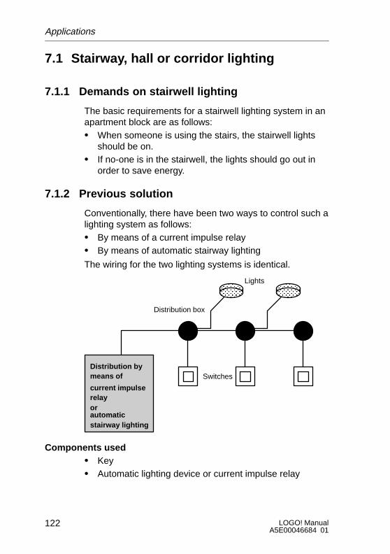
LOGO! ManualA5E00046684 01
122
7.1 Stairway, hall or corridor lighting
7.1.1 Demands on stairwell lighting
The basic requirements for a stairwell lighting system in anapartment block are as follows:S When someone is using the stairs, the stairwell lights
should be on.S If no-one is in the stairwell, the lights should go out in
order to save energy.
7.1.2 Previous solution
Conventionally, there have been two ways to control such alighting system as follows:S By means of a current impulse relayS By means of automatic stairway lighting
The wiring for the two lighting systems is identical.
ÎÎÎÎÎÎÎÎÎÎÎÎ ÎÎÎ
ÎÎÎÎÎÎÎÎÎ
Lights
SwitchesDistribution by means of
current impulserelayorautomaticstairway lighting
Distribution box
Components usedS KeyS Automatic lighting device or current impulse relay
Applications

123LOGO! ManualA5E00046684 01
Lighting system with a current impulse relay
When a current impulse relay is used, the lighting systembehaves as follows:S When any switch is pressed: the lighting is switched onS When any switch is pressed again: the lighting is
switched off
Disadvantage: people frequently forget to switch the lightsoff.
Lighting system with an automatic lighting device
When an automatic device is used, the lighting system be-haves as follows:S When any switch is pressed: the lighting is switched onS When the preset time has elapsed, the lights switch off
automatically.
Disadvantage: The lighting cannot be switched on for anextended period of time (e.g. for cleaning purposes). Thepermanent on switch is usually on the stairwell lightingtimer unit which may be difficult or impossible to gain ac-cess to.
7.1.3 Lighting system with LOGO!
You can use a LOGO! module to replace the stairwell light-ing timer or the current impulse relay. And you can imple-ment both functions (timed off-delay and current impulserelay) in a single unit. What is more, you can incorporateextra functions without making any alterations to the wiring.Here are some examples:S Current impulse relay with LOGO!S Automatic stairway lighting system with LOGO!S LOGO! as a multifunctional switching system with the
following functions:– Light on: Press switch
(Light switches off after the set time elapses)– Permanent light on: Press switch twice– Light off: Press switch for 2 seconds
Applications
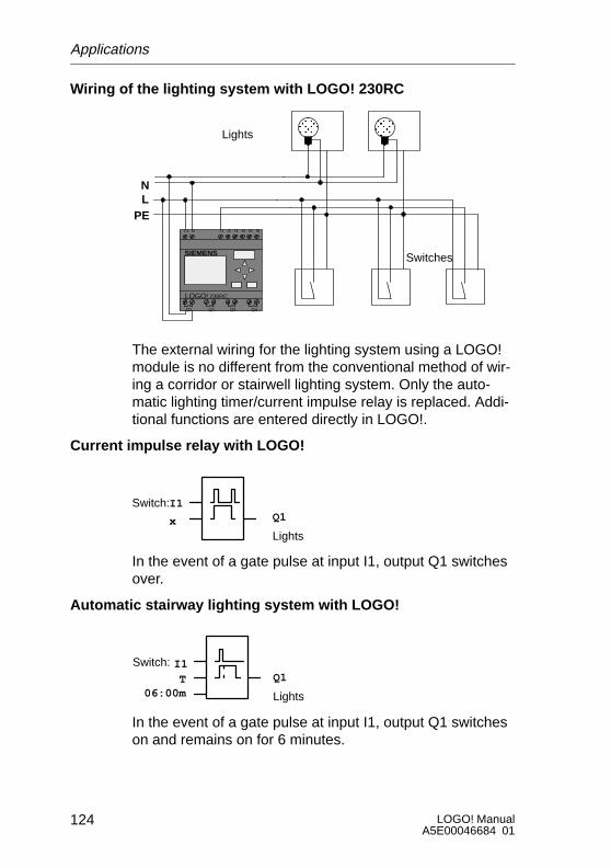
LOGO! ManualA5E00046684 01
124
Wiring of the lighting system with LOGO! 230RC
ÏÏÏÏ
ÏÏÏÏ
Lights
Switches
L1 N I1 I2 I3 I4 I5 I6
Q1 Q2 Q3 Q4
SIEMENS
LN
PE
LOGO! 230RC
The external wiring for the lighting system using a LOGO!module is no different from the conventional method of wir-ing a corridor or stairwell lighting system. Only the auto-matic lighting timer/current impulse relay is replaced. Addi-tional functions are entered directly in LOGO!.
Current impulse relay with LOGO!
I1Switch:Q1
Lightsx
In the event of a gate pulse at input I1, output Q1 switchesover.
Automatic stairway lighting system with LOGO!
I1Switch:Q1
Lights
T06:00m
In the event of a gate pulse at input I1, output Q1 switcheson and remains on for 6 minutes.
Applications
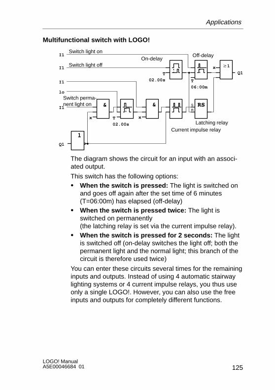
125LOGO! ManualA5E00046684 01
Multifunctional switch with LOGO!
Switch light on
Switch perma-nent light on
Switch light off
Off-delay
Latching relayCurrent impulse relay
On-delay
& &
x T
02.00s
x
T
02.00s
w1
T
06:00m
xQ1
Q1
I1
I1
I1
I1
lo
The diagram shows the circuit for an input with an associ-ated output.
This switch has the following options:S When the switch is pressed: The light is switched on
and goes off again after the set time of 6 minutes(T=06:00m) has elapsed (off-delay)
S When the switch is pressed twice: The light isswitched on permanently (the latching relay is set via the current impulse relay).
S When the switch is pressed for 2 seconds: The lightis switched off (on-delay switches the light off; both thepermanent light and the normal light; this branch of thecircuit is therefore used twice)
You can enter these circuits several times for the remaininginputs and outputs. Instead of using 4 automatic stairwaylighting systems or 4 current impulse relays, you thus useonly a single LOGO!. However, you can also use the freeinputs and outputs for completely different functions.
Applications

LOGO! ManualA5E00046684 01
126
7.1.4 Special features and enhancement options
Features such as the following are available for addingfunctions or saving energy:S You can have the light flash before it goes off automati-
cally.S You can integrate various central functions:
– Central off– Central on (panic button)– Control of all lights or individual circuits by a daylight
control switch– Control by the integrated time switch
(e.g. permanent light only until 24.00 hours; no enab-ling at certain times)
– Automatic switching off of the permanent light after apreset time has elapsed (e.g. after 3 hours)
Applications
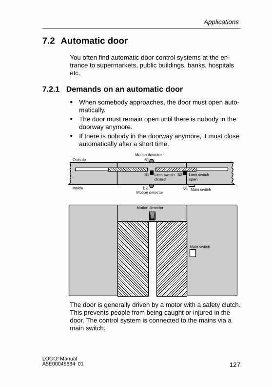
127LOGO! ManualA5E00046684 01
7.2 Automatic door
You often find automatic door control systems at the en-trance to supermarkets, public buildings, banks, hospitalsetc.
7.2.1 Demands on an automatic door
S When somebody approaches, the door must open auto-matically.
S The door must remain open until there is nobody in thedoorway anymore.
S If there is nobody in the doorway anymore, it must closeautomatically after a short time.
ÌÌÌÌÌÌÌÌÌÌ
ÑÑÑÑÑÑÑÑÑÑ
ÑÑÑÑÑÑÑÑÑÑÑÑÑÑÑÑÑÑÑÑÑÑÑÑÑÑÑÑÑÑÑÑ
ÌÌÌÌÌÌÌÌÌÌÌÌÌÌÌÌÌÌÌÌÌÌÌÌÌÌÌÌÌÌÌÌ
Outside
Inside
B1
B2
Limit switchclosed
Limit switchopen
Main switch
Q1
S1 S2
Motion detector
Main switch
Motion detector
Motion detector
The door is generally driven by a motor with a safety clutch.This prevents people from being caught or injured in thedoor. The control system is connected to the mains via amain switch.
Applications

LOGO! ManualA5E00046684 01
128
7.2.2 Previous solution
K1 K2
K2 K1
K3 K3
Open Close
S2 S1
K3
B1 B2 K3
K4
K4
B2
K3
B1
S2
Open door Waiting time
Auxiliary circuit
L1
N
As soon as one of the motion detectors B1 or B2 registerssomebody’s presence, the door is opened by K3.
If the two motion detectors detect nothing for a minimumperiod, K4 enables the close operation.
7.2.3 Door control system with LOGO!
LOGO! allows you to considerably simplify the circuit. Youneed only connect the motion detectors, the limit switchesand the master contactors to LOGO!.
Applications
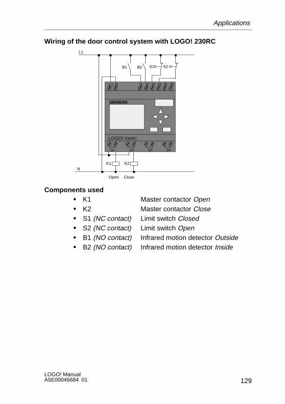
129LOGO! ManualA5E00046684 01
Wiring of the door control system with LOGO! 230RC
L1 N I1 I2 I3 I4 I5 I6
Q1 Q2 Q3 Q4
SIEMENS
K1 K2
Open Close
B1 B2 S2S1
L1
N
LOGO! 230RC
Components usedS K1 Master contactor OpenS K2 Master contactor CloseS S1 (NC contact) Limit switch ClosedS S2 (NC contact) Limit switch OpenS B1 (NO contact) Infrared motion detector OutsideS B2 (NO contact) Infrared motion detector Inside
Applications
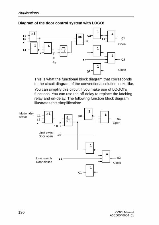
LOGO! ManualA5E00046684 01
130
Diagram of the door control system with LOGO!
& 1
1
1
&
I4
I3
Q2
Q1
RSI1I2
1I4
T=4s
Close
Openx
&
x
Q1
Q2
This is what the functional block diagram that correspondsto the circuit diagram of the conventional solution looks like.
You can simplify this circuit if you make use of LOGO!’sfunctions. You can use the off-delay to replace the latchingrelay and on-delay. The following function block diagramillustrates this simplification:
& 1
1
1
&
I4
I3
I1
I2x
Q2
Q1
x10 s
Close
Open
Limit switchDoor closed
Limit switchDoor open
Motion de-tector
Q1
Q2
Applications

131LOGO! ManualA5E00046684 01
7.2.4 Special features and enhancement options
Functionality and user friendliness can be improved in thefollowing ways, for example:S You can connect an additional control switch: Open –
Automatic – Closed (O-A-C)S You can connect a buzzer to one of LOGO!’s outputs to
indicate when the door is about to close.S You can include time and direction-dependent enabling
of door opening (so that it only opens during shop open-ing hours or only from the inside to the outside afterclosing time).
7.2.5 Enhanced LOGO! 230RC solution
Wiring of the enhanced LOGO! solution
L1 N I1 I2 I3 I4 I5 I6
Q1 Q2 Q3 Q4
SIEMENS
K1 K2
Open Close
B1 B2 S2S1
L1
N
Buzzer
S3 O-A-G
H1
LOGO! 230RC
Applications

LOGO! ManualA5E00046684 01
132
Functional block diagram of the enhanced LOGO! solution
x
x
x
x
No1:Day= Mo..FrOn = 09:00Off =18:00No2:Day= SaOn = 08:00Off =13:00
No1:Day= Mo..FrOn = 09:00Off =19:00No2:Day= SaOn = 08:00Off =14:00
I1
I2
Motion detector B1
Motion detector B2
T= 10 s
x
I5Control switchDoor open
Q2Close output
I4
Limit switchDoor open
Q1Open
Q2Close
xQ1
I1I2
Open output
Motion detector B1Motion detector B2
I3Limit switchDoor closed
I6Control switchClose door
Detecting motion
Motor for opening
Motor for closing
Applications

133LOGO! ManualA5E00046684 01
Detecting motion
During business hours, motion detector B1 opens the dooras soon as somebody wants to enter the shop from out-side. Motion detector B2 opens the door if somebody wantsto leave the shop.
After closing time, motion detector B2 continues to openthe door for 1 hour so that customers can leave the shop.
Motor for opening
Output Q1 is switched on and opens the door when thefollowing occurs:S The control switch at 15 is operated (the door is to be
constantly open) orS The motion detectors indicate that somebody is ap-
proaching the door andS The door is not yet fully open (limit switch at I4).
Motor for closing
Output Q2 is switched on and closes the door when thefollowing occurs:S The control switch at 16 is operated (the door is to be
constantly closed) orS The motion detectors indicate that there is nobody near
the door andS The door is not yet fully closed (limit switch at I3).
Buzzer
Connect the buzzer to output Q3. The buzzer sounds for ashort time (in this case 1 second) when the door is closed.Enter the following circuit at Q3 in the block diagram:
T= 1 s
x Q3Buzzer
Q2Close output
Applications
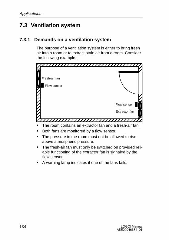
LOGO! ManualA5E00046684 01
134
7.3 Ventilation system
7.3.1 Demands on a ventilation system
The purpose of a ventilation system is either to bring freshair into a room or to extract stale air from a room. Considerthe following example:
ÉÉÉÉÉÉÉÉÉÉÉÉÉÉÉÉÉÉÉÉÉÉÉÉÉÉÉÉÉÉÉÉÉÉÉÉÉÉÉÉÉÉÉÉÉÉÉÉÉÉÉÉÉÉÉÉÉÉÉÉÉÉÉÉÉÉÉÉÉÉÉÉÉÉÉÉÉÉÉÉÉÉÉÉÉÉÉÉÉÉÉÉÉÉÉÉÉÉÉÉÉÉÉÉÉÉÉÉÉÉÉÉÉÉÉÉÉÉÉÉÉÉÉÉÉÉÉÉÉÉÉÉÉÉÉÉÉÉÉÉÉÉÉÉÉÉÉÉÉÉÉÉÉÉÉÉÉÉÉÉÉÉÉÉÉÉÉÉÉÉÉÉÉÉÉÉÉÉÉÉ
Fresh-air fan
Flow sensor
Extractor fan
Flow sensor
S The room contains an extractor fan and a fresh-air fan.S Both fans are monitored by a flow sensor.S The pressure in the room must not be allowed to rise
above atmospheric pressure.S The fresh-air fan must only be switched on provided reli-
able functioning of the extractor fan is signaled by theflow sensor.
S A warning lamp indicates if one of the fans fails.
Applications
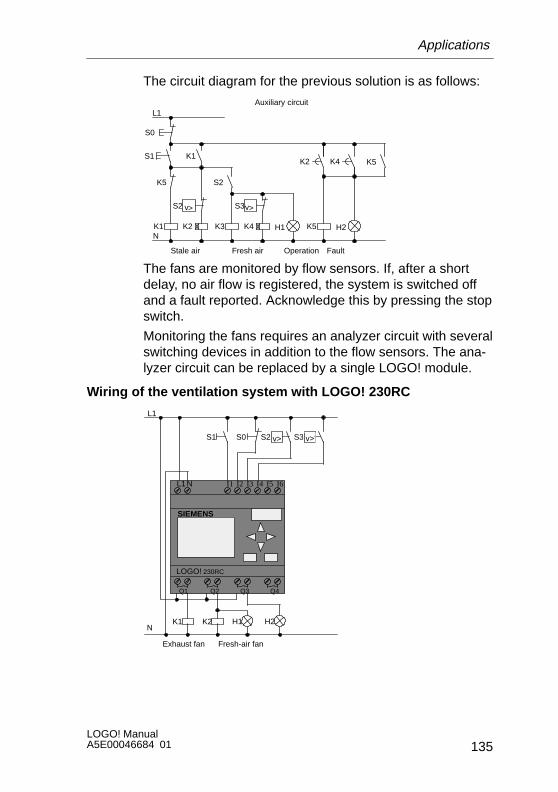
135LOGO! ManualA5E00046684 01
The circuit diagram for the previous solution is as follows:
K1 K5
K5
S1
Stale air Fresh air
S0
K3K2
Operation
Auxiliary circuitL1
N
S2
K1
v>
S2
H1K4
S3v>
K5
Fault
H2
K2 K4
The fans are monitored by flow sensors. If, after a shortdelay, no air flow is registered, the system is switched offand a fault reported. Acknowledge this by pressing the stopswitch.
Monitoring the fans requires an analyzer circuit with severalswitching devices in addition to the flow sensors. The ana-lyzer circuit can be replaced by a single LOGO! module.
Wiring of the ventilation system with LOGO! 230RC
L1N I1 I2 I3 I4 I5 I6
Q1 Q2 Q3 Q4
SIEMENS
K1 K2
Exhaust fan Fresh-air fan
S1
L1
N
S2 S3 v>v>
H1 H2
S0
LOGO! 230RC
Applications
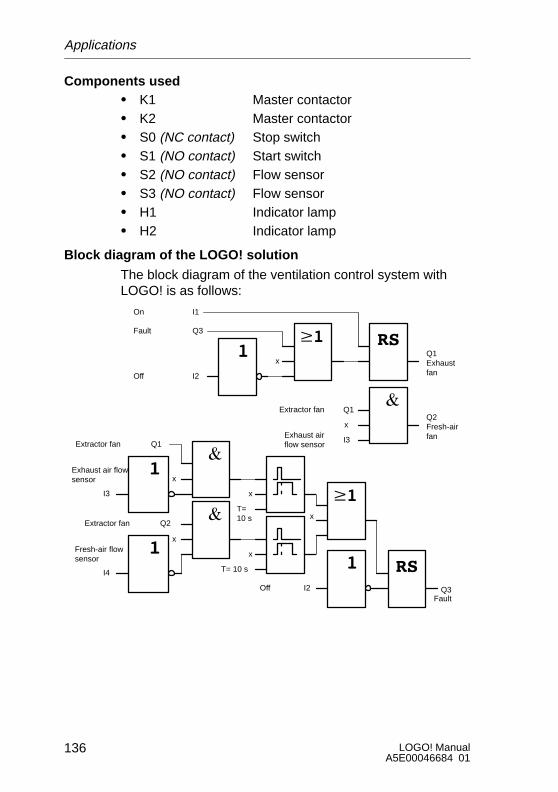
LOGO! ManualA5E00046684 01
136
Components usedS K1 Master contactorS K2 Master contactorS S0 (NC contact) Stop switchS S1 (NO contact) Start switchS S2 (NO contact) Flow sensorS S3 (NO contact) Flow sensorS H1 Indicator lampS H2 Indicator lamp
Block diagram of the LOGO! solution
The block diagram of the ventilation control system withLOGO! is as follows:
x
I1On
Q3Fault
I2Off
Q1Exhaustfan
Q2Fresh-airfan
Q1Extractor fan
I3Exhaust airflow sensor
x
I2OffFault
x
T=10 s
x
T= 10 s
x
x
x
I3
Exhaust air flowsensor
I4
Fresh-air flowsensor
Extractor fan Q1
Extractor fan Q2
Q3
Applications

137LOGO! ManualA5E00046684 01
7.3.2 Advantages of using LOGO!
If you use a LOGO! module you require fewer switchingdevices. That saves you installation time and space in thecontrol cabinet. Under certain circumstances it may evenallow you to use a smaller control cabinet.
Additional options when using LOGO!S The free output (Q4) can be used as a potential-free
signaling contact in the event of a fault or a power fail-ure.
S It is possible to stagger the switching-off of the fans.
These functions can be implemented without additionalswitching devices.
Functional block diagram of the enhanced LOGO! solution
The fans at Q1 and Q2 are switched on and off as shown inthe following circuit:
x
T=10 s
T=30 s
Q1Exhaustfan
Q2Fresh-airfan
On
I2
Off
Fault Q3
x
x
I3Exhaust air flowsensor
I2OffFault
T=10 s
T=10 s
x
x
x
I3
Exhaust air flowsensor
I4
Fresh-air flowsensor
Q1 exhaust fan
Q2 exhaust fan
Q3
I1
Applications

LOGO! ManualA5E00046684 01
138
You can also generate a message via output Q4:
Q3Fault
Q4Message
The relay contacts of output Q4 are always closed whenthe system is running. Relay Q4 does not release unlessthere is a power failure or a fault in the system. This con-tact can be used for teleindication, for example.
Applications
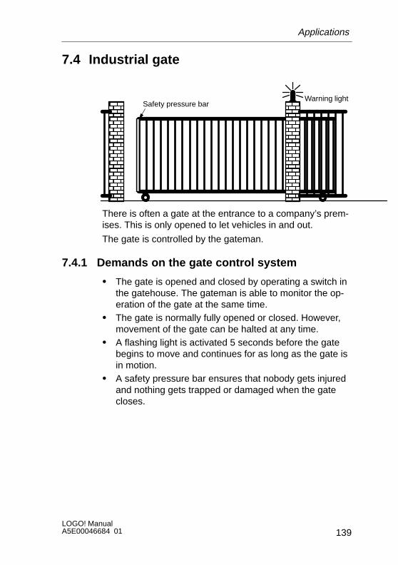
139LOGO! ManualA5E00046684 01
7.4 Industrial gate
ÔÔÔÔÔÔÔÔÔÔÔÔÔÔÔÔ
ÔÔÔÔÔÔÔÔÔÔÔÔÔÔÔÔ
Warning lightSafety pressure bar
There is often a gate at the entrance to a company’s prem-ises. This is only opened to let vehicles in and out.
The gate is controlled by the gateman.
7.4.1 Demands on the gate control system
S The gate is opened and closed by operating a switch inthe gatehouse. The gateman is able to monitor the op-eration of the gate at the same time.
S The gate is normally fully opened or closed. However,movement of the gate can be halted at any time.
S A flashing light is activated 5 seconds before the gatebegins to move and continues for as long as the gate isin motion.
S A safety pressure bar ensures that nobody gets injuredand nothing gets trapped or damaged when the gatecloses.
Applications
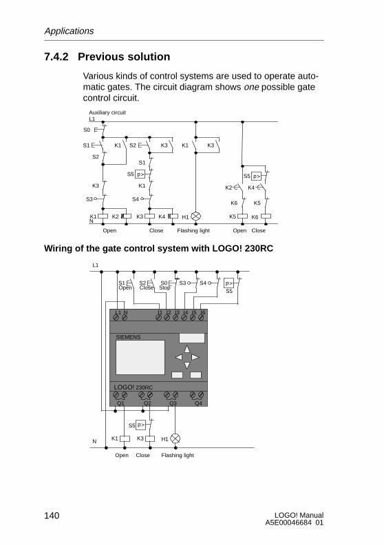
LOGO! ManualA5E00046684 01
140
7.4.2 Previous solution
Various kinds of control systems are used to operate auto-matic gates. The circuit diagram shows one possible gatecontrol circuit.
K1 K5
K3
S1
Open Close
S0
K3K2
Flashing light
Auxiliary circuitL1
N
K1
H1K4
S5 p>
K6
K6
K1
S2
S2 K3
K2 K4
Open Close
K5
S5 p>
S1
K3 K1
S4S3
Wiring of the gate control system with LOGO! 230RC
L1 N I1 I2 I3 I4 I5 I6
Q1 Q2 Q3 Q4
SIEMENS
K1 K3
Open Close
S4S3
L1
N
S1 S2 S0
S5
p>
S5 p>
Flashing light
H1
Open Close Stop
LOGO! 230RC
Applications

141LOGO! ManualA5E00046684 01
Components usedS K1 Master contactorS K2 Master contactorS S0 (NC contact) Stop switchS S1 (NO contact) Open switchS S2 (NO contact) Close switchS S3 (NC contact) Open position switchS S4 (NC contact) Closed position switchS S5 (NC contact) Safety pressure bar
Functional diagram of the LOGO! solution
T=5 s
T=5 s
x
x
x
x
Q1Open
Q3Flas-hinglight
Q2Close
I3
I4
I3
I6
I5
I1
I2
Q2
Q1
Safety bar
Gate is closed
Gate isopen
Stop switch
OpenStart switch
Stop switch
Close startswitch
T=2 s
I2
I1Open start switch
Close startswitch
Closestartswitch
The open and close start switches move the gate in theappropriate direction provided it is not already moving inthe other direction. Movement of the gate is halted by thestop switch or the relevant limit switch. The gate is alsoprevented from closing by the safety bar.
Applications
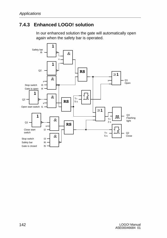
LOGO! ManualA5E00046684 01
142
7.4.3 Enhanced LOGO! solution
In our enhanced solution the gate will automatically openagain when the safety bar is operated.
xx
I6Safety bar
x
Q2
I3
I4Gate is open
Stop switch
x
I1
Q2
Open start switch
T=5 s
Q1Open
T=5 s
x
Q2Close
I3
I6
I5
I2
Q1
Safety bar
Gate is closed
Stop switch
Close startswitch
Q3Flashinglight
T=2 s
Applications
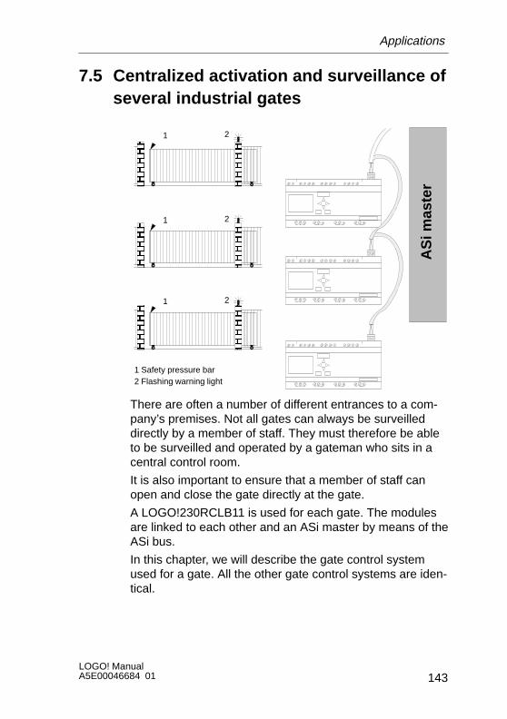
143LOGO! ManualA5E00046684 01
7.5 Centralized activation and surveillance ofseveral industrial gates
ÔÔÔ
ÔÔÔÔÔÔ
ÔÔÔ
ÔÔÔÔÔÔ
1 Safety pressure bar 2 Flashing warning light
AS
i mas
ter
ÔÔÔÔ
ÔÔÔÔÔÔÔÔ
1 2
1 2
1 2
There are often a number of different entrances to a com-pany’s premises. Not all gates can always be surveilleddirectly by a member of staff. They must therefore be ableto be surveilled and operated by a gateman who sits in acentral control room.
It is also important to ensure that a member of staff canopen and close the gate directly at the gate.
A LOGO!230RCLB11 is used for each gate. The modulesare linked to each other and an ASi master by means of theASi bus.
In this chapter, we will describe the gate control systemused for a gate. All the other gate control systems are iden-tical.
Applications

LOGO! ManualA5E00046684 01
144
7.5.1 Demands on the gate control system
S Each gate is opened and closed by means of a pull-cordswitch. The gate is normally fully opened or closed.
S Each gate can also be opened and closed usingswitches at the gate.
S The ASi bus connection enables the gateman to openand close the gate from the gatehouse. The state GATEOPEN or GATE CLOSED is indicated in the gatehouse.
S A flashing light is activated 5 seconds before the gatebegins to move and continues for as long as the gate isin motion.
S A safety pressure bar ensures that nobody gets injuredand nothing gets trapped or damaged when the gatecloses.
Applications

145LOGO! ManualA5E00046684 01
Wiring of the gate control system with LOGO! 230RCLB11
N
L1 N I1 I2 I3 I4
Q1 Q3 Q4
SIEMENS
I5 I6
Q2 Q5 Q6 Q7 Q8
Output 8x
I7 I8
AS interface
– +I9 I10 I11 I12
K1 K2
L1
Gateclosed
Gateopen
Flashinglight
S0 S1 S2 S3 S4 S5 S6
p>
S6
p>
Components usedS K1 Master contactor openingS K2 Master contactor closingS S0 (NO contact) OPEN pull-cord switchS S1 (NO contact) CLOSE pull-cord switchS S2 (NO contact) OPEN switchS S3 (NO contact) CLOSE switchS S4 (NC contact) OPEN GATE position switchS S5 (NC contact) CLOSE GATE position switchS S6 (NC contact) Safety pressure bar
Applications

LOGO! ManualA5E00046684 01
146
Higher-level control systemS Qa1 GATE OPEN position switchS Qa2 GATE CLOSED position switchS Ia1 External OPEN GATE switchS Ia2 External CLOSE GATE switch
Applications
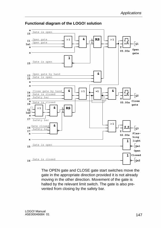
147LOGO! ManualA5E00046684 01
Functional diagram of the LOGO! solution
Cl.
Safety bar
Gate is closed
Gate is closed
T
05.00s
w1
Q1I1
I2
I3
I5
Ia1
x
I6I4
Q2
x
Ia2
Open
gate
&w1
&
=1 &
w1
&
&
& w1
w1
I5
x
I5x
x
I7x
I6
I7
x
I6I7
x
Q3
Qa1
x
Qa2
I5
I6
T
05.00s
T
02.00s
Close
gate
Flas-
hing
light
Gate is open
Open gateOpen gate
Gate is open
Gate is openOpen gate by hand
Close gate by hand
Safety bar
Safety bar
Cl.
Gate closed
Gate is closed
Gate is open
Closed
Open
The OPEN gate and CLOSE gate start switches move thegate in the appropriate direction provided it is not alreadymoving in the other direction. Movement of the gate ishalted by the relevant limit switch. The gate is also pre-vented from closing by the safety bar.
Applications

LOGO! ManualA5E00046684 01
148
7.6 Fluorescent lamps
ÉÉÉÉÉÉÉÉÉÉÉÉÉÉÉÉÉÉÉÉÉÉÉÉÉÉÉÉÉÉÉÉÉÉÉÉÉÉÉÉÉÉÉÉÉÉÉÉÉÉÉÉÉÉÉÉÉÉÉÉÉÉÉÉÉÉÉÉÉÉÉÉÉÉÉÉÉÉÉÉÉÉÉÉÉÉÉÉÉÉÉÉÉÉÉÉÉÉÉÉÉÉÉÉÉÉÉÉÉÉÉÉÉÉÉÉÉÉÉÉ
Fluorescent lamp 2Fluorescent lamp 1
Fluorescent lamp 4Fluorescent lamp 3
ÉÉÉ
ÉÉÉÉ
ÉÉ
ÉÉÉÉ
ÉÉÉÉÉÉÉÉÉÉÉÉÉÉÉÉÉÉÉÉÉÉÉÉÉÉÉÉÉÉÉÉÉÉ
Corridor
Office
When lighting systems are planned in companies, the typeand number of lamps used depends on the level of lightingrequired. For reasons of cost efficiency, fluorescent lampsarranged in rows of tubes are often used. They are subdi-vided into switching groups according to how the room isused.
7.6.1 Demands on the lighting system
S The lamps are switched on and off locally.S If there is sufficient natural light, the lamps on the win-
dow side of the room are automatically switched off bymeans of a brightness-sensitive switch.
S The lights are switched off automatically at 20.00.S It must be possible at all times to switch the lights on
and off locally.
Applications
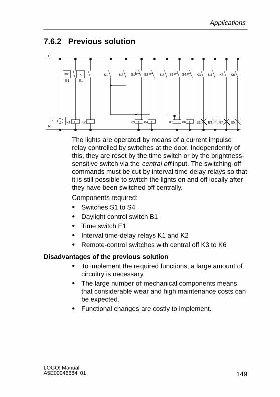
149LOGO! ManualA5E00046684 01
7.6.2 Previous solution
B1
L1
N
E1
E1
lx> K6
E5
K5
E4
K4
E3
K3
E2K3 K4 K5 K6
S1 S2 S3 S4
K1 K2
K2K2K1
The lights are operated by means of a current impulserelay controlled by switches at the door. Independently ofthis, they are reset by the time switch or by the brightness-sensitive switch via the central off input. The switching-offcommands must be cut by interval time-delay relays so thatit is still possible to switch the lights on and off locally afterthey have been switched off centrally.
Components required:S Switches S1 to S4S Daylight control switch B1S Time switch E1S Interval time-delay relays K1 and K2S Remote-control switches with central off K3 to K6
Disadvantages of the previous solutionS To implement the required functions, a large amount of
circuitry is necessary.S The large number of mechanical components means
that considerable wear and high maintenance costs canbe expected.
S Functional changes are costly to implement.
Applications
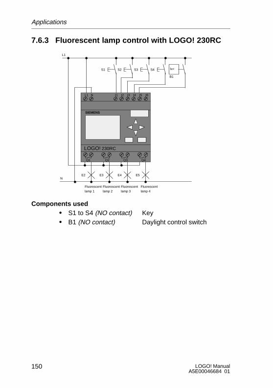
LOGO! ManualA5E00046684 01
150
7.6.3 Fluorescent lamp control with LOGO! 230RC
L1 N I1 I2 I3 I4 I5 I6
Q1 Q2 Q3 Q4
SIEMENS
L1
NE2 E3 E4
B1
lx<
Fluorescentlamp 1
E5
Fluorescentlamp 2
Fluorescentlamp 3
Fluorescentlamp 4
S1 S2 S3 S4
LOGO! 230RC
Components usedS S1 to S4 (NO contact) KeyS B1 (NO contact) Daylight control switch
Applications

151LOGO! ManualA5E00046684 01
Functional diagram of the LOGO! solution
x
T=1s
Q2
Mo..Su20:00 – 20.01
Mo..Su21:00 – 21.01
Switch-off pulse generated by time switch
I5
T=1s
Daylight con-trol switch
x
I5
Switch-off pulse generated by daylight control switch
I1
I2
I3
I4
x
x
Q1
Q4
Q3
Lamp 3Corridor side
Lamp 4Corridor side
Lamp 1Window side
Lamp 2Window side
Advantages of the LOGO! solutionS You can connect the lamps directly to LOGO! provided
the switching capacity of the individual outputs is notexceeded. In the case of greater capacities, you shoulduse a power contactor.
S Connect the brightness-sensitive switch directly to oneof LOGO!’s inputs.
S You don’t need a time switch since this function is inte-grated in LOGO!.
S The fact that fewer switching devices are requiredmeans that you can install a smaller sub-distribution unitand thus save space.
S Fewer devices are requiredS The lighting system can be easily modified.S Additional switching times can be set as required (stag-
gered switch-off pulses at the end of the day).S The brightness-sensitive switch function can easily be
applied to all lamps or an altered group of lamps.
Applications
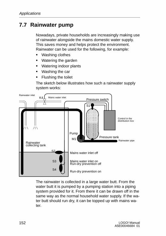
LOGO! ManualA5E00046684 01
152
7.7 Rainwater pump
Nowadays, private households are increasingly making useof rainwater alongside the mains domestic water supply.This saves money and helps protect the environment.Rainwater can be used for the following, for example:S Washing clothesS Watering the gardenS Watering indoor plantsS Washing the carS Flushing the toilet
The sketch below illustrates how such a rainwater supplysystem works:
ÕÕÕÕÕÕÕÕÕŠŠ
ŠŠ
ÎÎÎÎÎÎÎÎÎÎÎÎÎÎÎÎÎÎ
Run-dry prevention on
Mains water inlet onRun-dry prevention off
Mains water inlet off
PumpPressure tank
Pressure switch
S1
ÕÕÕÕÕÕ
S2
S3
S4
M1Rainwatercollecting tank
Rainwater pipe
Control in thedistribution box
Mains water inletK4Rainwater inlet
The rainwater is collected in a large water butt. From thewater butt it is pumped by a pumping station into a pipingsystem provided for it. From there it can be drawn off in thesame way as the normal household water supply. If the wa-ter butt should run dry, it can be topped up with mains wa-ter.
Applications
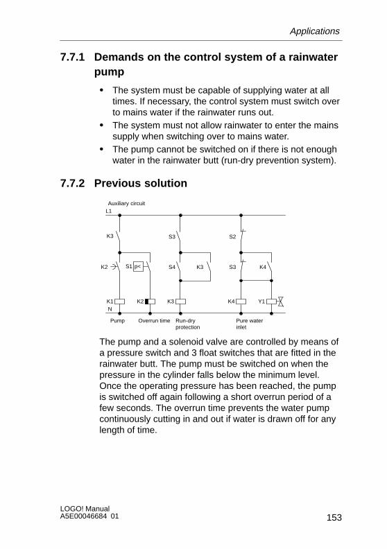
153LOGO! ManualA5E00046684 01
7.7.1 Demands on the control system of a rainwaterpump
S The system must be capable of supplying water at alltimes. If necessary, the control system must switch overto mains water if the rainwater runs out.
S The system must not allow rainwater to enter the mainssupply when switching over to mains water.
S The pump cannot be switched on if there is not enoughwater in the rainwater butt (run-dry prevention system).
7.7.2 Previous solution
K1 K2
K3
Pump Overrun time
S1
K3
S4 K3
Run-dryprotection
Auxiliary circuitL1
NK4
S3 K4
Pure waterinlet
p<K2
S3 S2
Y1
The pump and a solenoid valve are controlled by means ofa pressure switch and 3 float switches that are fitted in therainwater butt. The pump must be switched on when thepressure in the cylinder falls below the minimum level.Once the operating pressure has been reached, the pumpis switched off again following a short overrun period of afew seconds. The overrun time prevents the water pumpcontinuously cutting in and out if water is drawn off for anylength of time.
Applications
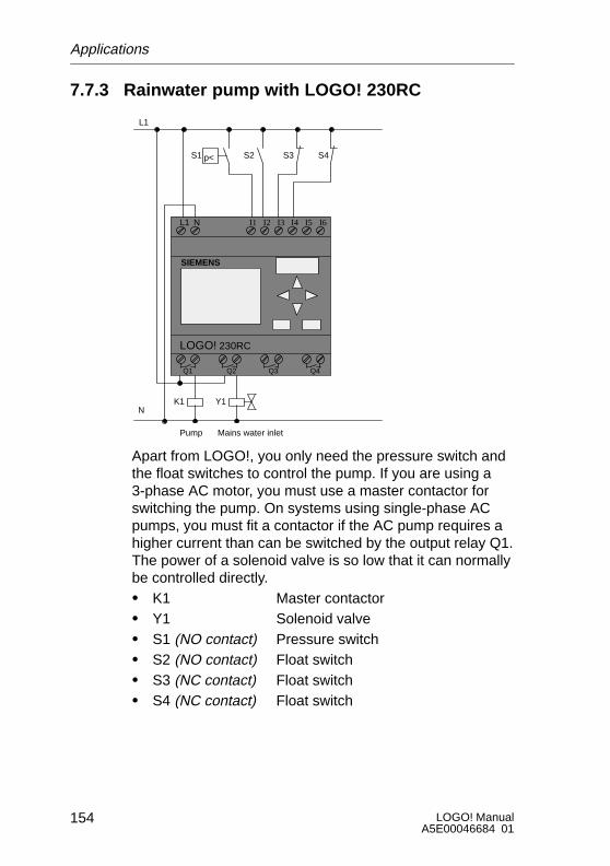
LOGO! ManualA5E00046684 01
154
7.7.3 Rainwater pump with LOGO! 230RC
L1 N I1 I2 I3 I4 I5 I6
Q1 Q2 Q3 Q4
SIEMENS
K1 Y1
Pump
S4S3
L1
N
S1 S2p<
Mains water inlet
LOGO! 230RC
Apart from LOGO!, you only need the pressure switch andthe float switches to control the pump. If you are using a3-phase AC motor, you must use a master contactor forswitching the pump. On systems using single-phase ACpumps, you must fit a contactor if the AC pump requires ahigher current than can be switched by the output relay Q1.The power of a solenoid valve is so low that it can normallybe controlled directly.S K1 Master contactorS Y1 Solenoid valveS S1 (NO contact) Pressure switchS S2 (NO contact) Float switchS S3 (NC contact) Float switchS S4 (NC contact) Float switch
Applications
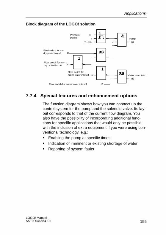
155LOGO! ManualA5E00046684 01
Block diagram of the LOGO! solution
I2
Float switch formains water inlet off Mains water inlet
Q2
Float switch for mains water inlet off
I1Pressureswitch
I3
Float switch for run-dry protection on I4
Float switch for run-dry protection off
x
T = 20 s x
PumpQ1
I3
7.7.4 Special features and enhancement options
The function diagram shows how you can connect up thecontrol system for the pump and the solenoid valve. Its lay-out corresponds to that of the current flow diagram. Youalso have the possibility of incorporating additional func-tions for specific applications that would only be possiblewith the inclusion of extra equipment if you were using con-ventional technology, e.g.:S Enabling the pump at specific timesS Indication of imminent or existing shortage of waterS Reporting of system faults
Applications

LOGO! ManualA5E00046684 01
156
7.8 Other applications
In addition to the above applications, we have also put aselection of 23 further potential applications on the Internet(updated June 1999) at www.ad.siemens.de/logo/html_00/einsatz.htm.
The following are some of the examples you can find there:S Watering greenhouse plantsS Control of conveyor systemsS Control of a bending machineS Shop window lightingS Bell system (e.g. in a school)S Parking lot surveillanceS Exterior lightingS Control system for shuttersS Interior and exterior lighting for an apartment blockS Control system for a cream stirrerS Sports hall lightingS Equal distribution of 3 loadsS Sequence control system for cable-welding machines
with large cross-sectionsS Step switch (e.g. for fans)S Boiler sequence controlS Control system for several pump sets with centralized
operationS Cutting device (e.g. for detonating fuses)S Monitoring length of use (e.g. in solar energy system)S Intelligent foot buttons (e.g. to select speeds)S Control of an elevating platformS Impregnation of textiles – heating and conveyor control
systemS Silo-filling system
And many more.
Applications

157LOGO! ManualA5E00046684 01
You can also find descriptions and the relevant circuit dia-grams of the applications on the Internet. You can readthese *.pdf files with Adobe Acrobat Reader. And if youhave installed the LOGO!Soft or LOGO!Soft Comfort pro-gramming software on your PC, you can simply downloadthe relevant circuit diagrams at the touch of a button, adaptthem to your requirements, transfer them into LOGO! viathe PC cable and start to use them.
Advantages of using LOGO!
It is worth using LOGO! particularly when you:S Can replace a number of auxiliary switching devices
with the integrated functions of LOGO!.S Want to save yourself wiring and installation work (be-
cause the wiring is done in LOGO!).S Want to reduce the space required for components in
the control cabinet/distribution box. You may be able touse a smaller control cabinet/distribution box.
S Can add or change functions subsequently without hav-ing to install an additional switching device or changethe wiring.
S Have to provide your customers with additional func-tions for their domestic or building installation. Here aresome examples:– Home security: You can program LOGO! to switch a
lamp on regularly or open and close your shutterswhile you are on holiday.
– Heating system: You can program LOGO! to run thecirculation pump only when water or heat is reallyrequired.
– Cooling systems: You can program LOGO! to thawyour cooling systems automatically on a regular ba-sis to save energy costs.
– You can illuminate aquaria and terraria automaticallyon a time-dependent basis.
Applications

LOGO! ManualA5E00046684 01
158
You can also:S Use commercially available switches and buttons, which
makes it easy to integrate in the installation.S Connect LOGO! directly to your domestic installation
due to its integrated power supply.
Do you have any suggestions?
There are definitely more ways to use LOGO!. If you knowof one, why not write to us? We will collect all the sugges-tions we receive, and we intend to pass on as many as wecan. So drop us a line – no matter how unusual or simpleyour LOGO! circuit is! We would be delighted to receiveyour suggestions.
Write to:
Siemens AGA&D AS MVM – LOGO!Postfach 48 48
D-90327 Nürnberg
Applications

159LOGO! ManualA5E00046684 01
A Technical specificationsA.1 General technical specifications
Criterion Complies with Values
Dimensions WxHxDin mm
Weight
72 x 90 x 55with installation mecha-nism:72 x 90 x 59
Approx. 190 g
Installation On 35 mm DIN railwidth of 4 modules
Dimensions WxHxDin mm (LOGO!...L...)
Weight (LOGO!...L...)
126 x 90 x 55with installation mecha-nism:126 x 90 x 59
Approx. 360 g
Installation(LOGO!...L...)
On 35 mm DIN railwidth of 7 modules
Climatic environmental conditions
Ambient temperature
Horizontal installa-
Cold: IEC 68-2-1Heat: IEC 68 2 2*
0 ... 55 °CHorizontal installation
Vertical installation
IEC 68-2-2*0 ... 55 C
0 ... 55 °C
Storage/transport *40 °C ... +70 °C
Relative humidity IEC 68-2-30 From 5 to 95% no condensation
Air pressure 795 ... 1080 hPa
Pollutants IEC 68-2-42
IEC 68-2-43
SO2 10 cm3 /m3, 4 days
H2S 1 cm3 /m3, 4 days
Mechanical environmental conditions
Type of protection IP20
*IEC 68 includes VDE 0631
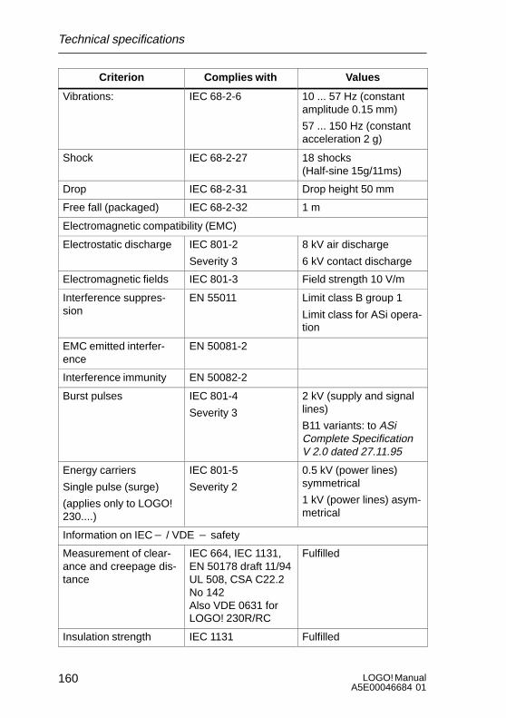
LOGO! ManualA5E00046684 01
160
Criterion ValuesComplies with
Vibrations: IEC 68-2-6 10 ... 57 Hz (constantamplitude 0.15 mm)
57 ... 150 Hz (constantacceleration 2 g)
Shock IEC 68-2-27 18 shocks (Half-sine 15g/11ms)
Drop IEC 68-2-31 Drop height 50 mm
Free fall (packaged) IEC 68-2-32 1 m
Electromagnetic compatibility (EMC)
Electrostatic discharge IEC 801-2
Severity 3
8 kV air discharge
6 kV contact discharge
Electromagnetic fields IEC 801-3 Field strength 10 V/m
Interference suppres-sion
EN 55011 Limit class B group 1
Limit class for ASi opera-tion
EMC emitted interfer-ence
EN 50081-2
Interference immunity EN 50082-2
Burst pulses IEC 801-4
Severity 3
2 kV (supply and signallines)
B11 variants: to ASiComplete SpecificationV 2.0 dated 27.11.95
Energy carriers
Single pulse (surge)
(applies only to LOGO!230....)
IEC 801-5
Severity 2
0.5 kV (power lines)symmetrical
1 kV (power lines) asym-metrical
Information on IEC* / VDE * safety
Measurement of clear-ance and creepage dis-tance
IEC 664, IEC 1131,EN 50178 draft 11/94UL 508, CSA C22.2No 142Also VDE 0631 forLOGO! 230R/RC
Fulfilled
Insulation strength IEC 1131 Fulfilled
Technical specifications

161LOGO! ManualA5E00046684 01
A.2 Technical specifications: LOGO! 230...
LOGO! 230RCLOGO! 230RCo
LOGO! 230RCLLOGO! 230RCLB11
Power supply
Input voltage 115/230 V AC 115/230 V AC
Permissible range 85 ... 250 V AC 85 ... 250 V AC
Permissible mains frequency: 47 ... 63 Hz 47 ... 63 Hz
Power consumption
S 115 V AC 10 30 mA 15 65 mAS 115 V AC 10 ... 30 mA 15 ... 65 mA
S 230 V AC 10 20 mA 15 40 mAS 230 V AC 10 ... 20 mA 15 ... 40 mA
Voltage failure bridging
S 115 V AC Typically 10 ms Typically 10 msS 115 V AC Typically 10 ms Typically 10 ms
S 230 V AC
y y
Typically 20 ms
y y
Typically 20 msS 230 V AC Typically 20 ms Typically 20 ms
Power loss at
S 115 V AC 1 1 3 5 W 1 7 7 5 WS 115 V AC 1.1 ... 3.5 W 1.7 ... 7.5 W
S 230 V AC 2 3 4 6 W 3 4 9 2 WS 230 V AC 2.3 ... 4.6 W 3.4 ... 9.2 W
Clock buffering at 25 _C Typically 80 h Typically 80 h
Accuracy of the real-timeclock
Max. "5 s /day Max. "5 s /day
Digital inputs
Number 6 12
Electrical isolation No No
Input voltage L1
S Signal 0 < 40 V AC < 40 V ACg
S Signal 1 > 79 V AC > 79 V AC
Input current at
S Signal 0
S Signal 1
< 0.03 mA
> 0 08 mA
< 0.03 mA
> 0 08 mAS Signal 1 > 0.08 mA > 0.08 mA
Technical specifications
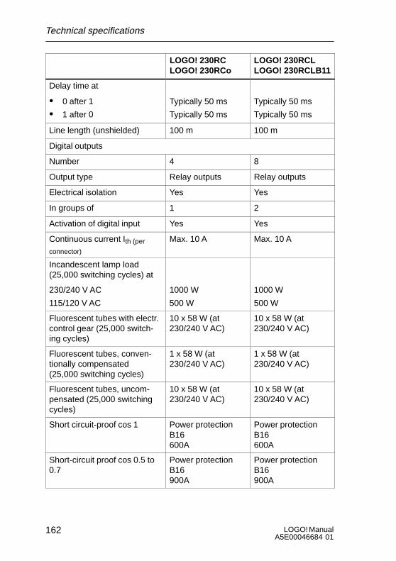
LOGO! ManualA5E00046684 01
162
LOGO! 230RCLLOGO! 230RCLB11
LOGO! 230RCLOGO! 230RCo
Delay time at
S 0 after 1 Typically 50 ms Typically 50 ms
S 1 after 0
y y
Typically 50 ms
y y
Typically 50 ms
Line length (unshielded) 100 m 100 m
Digital outputs
Number 4 8
Output type Relay outputs Relay outputs
Electrical isolation Yes Yes
In groups of 1 2
Activation of digital input Yes Yes
Continuous current Ith (per
connector)
Max. 10 A Max. 10 A
Incandescent lamp load(25,000 switching cycles) at
230/240 V AC
115/120 V AC
1000 W
500 W
1000 W
500 W
Fluorescent tubes with electr.control gear (25,000 switch-ing cycles)
10 x 58 W (at230/240 V AC)
10 x 58 W (at230/240 V AC)
Fluorescent tubes, conven-tionally compensated(25,000 switching cycles)
1 x 58 W (at230/240 V AC)
1 x 58 W (at230/240 V AC)
Fluorescent tubes, uncom-pensated (25,000 switchingcycles)
10 x 58 W (at230/240 V AC)
10 x 58 W (at230/240 V AC)
Short circuit-proof cos 1 Power protectionB16600A
Power protectionB16600A
Short-circuit proof cos 0.5 to0.7
Power protectionB16900A
Power protectionB16900A
Technical specifications
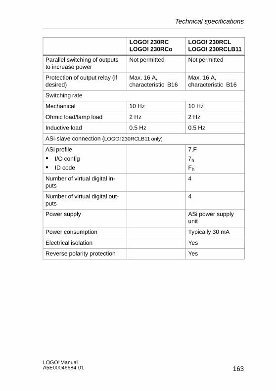
163LOGO! ManualA5E00046684 01
LOGO! 230RCLLOGO! 230RCLB11
LOGO! 230RCLOGO! 230RCo
Parallel switching of outputsto increase power
Not permitted Not permitted
Protection of output relay (ifdesired)
Max. 16 A,characteristic B16
Max. 16 A,characteristic B16
Switching rate
Mechanical 10 Hz 10 Hz
Ohmic load/lamp load 2 Hz 2 Hz
Inductive load 0.5 Hz 0.5 Hz
ASi-slave connection (LOGO! 230RCLB11 only)
ASi profile
S I/O config
S ID code
7.F
7h
Fh
Number of virtual digital in-puts
4
Number of virtual digital out-puts
4
Power supply ASi power supplyunit
Power consumption Typically 30 mA
Electrical isolation Yes
Reverse polarity protection Yes
Technical specifications
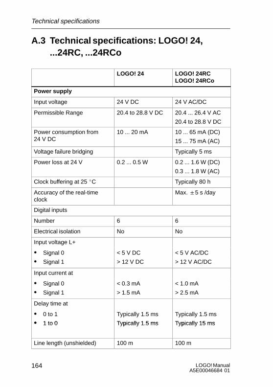
LOGO! ManualA5E00046684 01
164
A.3 Technical specifications: LOGO! 24,...24RC, ...24RCo
LOGO! 24 LOGO! 24RCLOGO! 24RCo
Power supply
Input voltage 24 V DC 24 V AC/DC
Permissible Range 20.4 to 28.8 V DC 20.4 ... 26.4 V AC
20.4 to 28.8 V DC
Power consumption from24 V DC
10 ... 20 mA 10 ... 65 mA (DC)
15 ... 75 mA (AC)
Voltage failure bridging Typically 5 ms
Power loss at 24 V 0.2 ... 0.5 W 0.2 ... 1.6 W (DC)
0.3 ... 1.8 W (AC)
Clock buffering at 25 _C Typically 80 h
Accuracy of the real-timeclock
Max. "5 s /day
Digital inputs
Number 6 6
Electrical isolation No No
Input voltage L+
S Signal 0 < 5 V DC < 5 V AC/DCg
S Signal 1 > 12 V DC > 12 V AC/DC
Input current at
S Signal 0 < 0.3 mA < 1.0 mAg
S Signal 1 > 1.5 mA > 2.5 mA
Delay time at
S 0 to 1
S 1 to 0
Typically 1.5 ms
Typically 1 5 ms
Typically 1.5 ms
Typically 15 msS 1 to 0 Typically 1.5 ms Typically 15 ms
Line length (unshielded) 100 m 100 m
Technical specifications

165LOGO! ManualA5E00046684 01
LOGO! 24RCLOGO! 24RCo
LOGO! 24
Digital outputs
Number 4 4
Output type Transistor,current-sourcing
Relay outputs
Electrical isolation No Yes
In groups of 1
Activation of digital input Yes
Output voltage ¢ Supply voltage
Output current Max. 0.3 A
Continuous current Ith Max. 10 A
Incandescent lamp load(25,000 switching cycles)
1000 W
Fluorescent tubes with electr.control gear (25,000 switch-ing cycles)
10 x 58 W
Fluorescent tubes, conven-tionally compensated(25,000 switching cycles)
1 x 58 W
Fluorescent tubes, uncom-pensated (25,000 switchingcycles)
10 x 58 W
Short circuit-proof and over-load-proof
Yes
Short-circuit current limiting Approx. 1 A
Derating None throughoutthe entire tempera-ture range
Short circuit-proof cos 1 Power protectionB16600A
Technical specifications
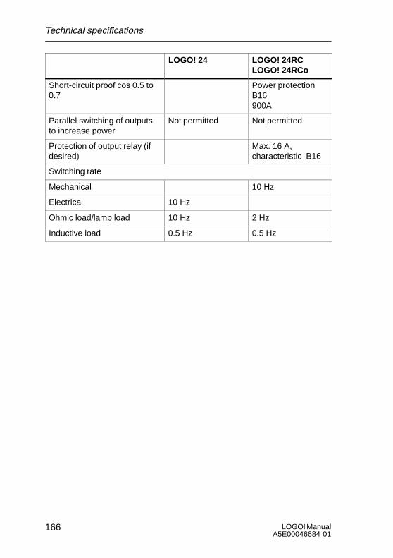
LOGO! ManualA5E00046684 01
166
LOGO! 24RCLOGO! 24RCo
LOGO! 24
Short-circuit proof cos 0.5 to0.7
Power protectionB16900A
Parallel switching of outputsto increase power
Not permitted Not permitted
Protection of output relay (ifdesired)
Max. 16 A,characteristic B16
Switching rate
Mechanical 10 Hz
Electrical 10 Hz
Ohmic load/lamp load 10 Hz 2 Hz
Inductive load 0.5 Hz 0.5 Hz
Technical specifications
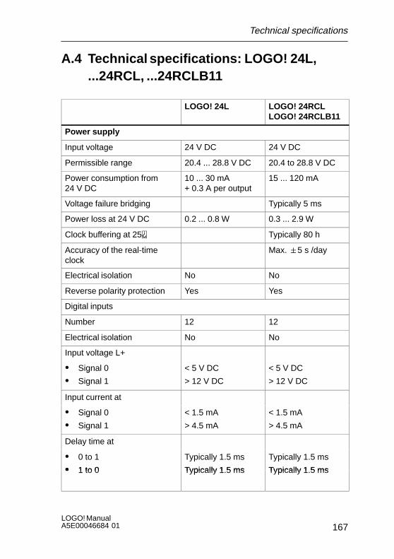
167LOGO! ManualA5E00046684 01
A.4 Technical specifications: LOGO! 24L,...24RCL, ...24RCLB11
LOGO! 24L LOGO! 24RCLLOGO! 24RCLB11
Power supply
Input voltage 24 V DC 24 V DC
Permissible range 20.4 ... 28.8 V DC 20.4 to 28.8 V DC
Power consumption from24 V DC
10 ... 30 mA+ 0.3 A per output
15 ... 120 mA
Voltage failure bridging Typically 5 ms
Power loss at 24 V DC 0.2 ... 0.8 W 0.3 ... 2.9 W
Clock buffering at 25 Typically 80 h
Accuracy of the real-timeclock
Max. "5 s /day
Electrical isolation No No
Reverse polarity protection Yes Yes
Digital inputs
Number 12 12
Electrical isolation No No
Input voltage L+
S Signal 0 < 5 V DC < 5 V DCg
S Signal 1 > 12 V DC > 12 V DC
Input current at
S Signal 0 < 1.5 mA < 1.5 mAg
S Signal 1 > 4.5 mA > 4.5 mA
Delay time at
S 0 to 1
S 1 to 0
Typically 1.5 ms
Typically 1 5 ms
Typically 1.5 ms
Typically 1 5 msS 1 to 0 Typically 1.5 ms Typically 1.5 ms
Technical specifications
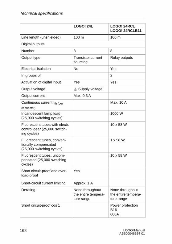
LOGO! ManualA5E00046684 01
168
LOGO! 24RCLLOGO! 24RCLB11
LOGO! 24L
Line length (unshielded) 100 m 100 m
Digital outputs
Number 8 8
Output type Transistor,current-sourcing
Relay outputs
Electrical isolation No Yes
In groups of 2
Activation of digital input Yes Yes
Output voltage ¢ Supply voltage
Output current Max. 0.3 A
Continuous current Ith (per
connector)
Max. 10 A
Incandescent lamp load(25,000 switching cycles)
1000 W
Fluorescent tubes with electr.control gear (25,000 switch-ing cycles)
10 x 58 W
Fluorescent tubes, conven-tionally compensated(25,000 switching cycles)
1 x 58 W
Fluorescent tubes, uncom-pensated (25,000 switchingcycles)
10 x 58 W
Short circuit-proof and over-load-proof
Yes
Short-circuit current limiting Approx. 1 A
Derating None throughoutthe entire tempera-ture range
None throughoutthe entire tempera-ture range
Short circuit-proof cos 1 Power protectionB16600A
Technical specifications

169LOGO! ManualA5E00046684 01
LOGO! 24RCLLOGO! 24RCLB11
LOGO! 24L
Short-circuit proof cos 0.5 to0.7
Power protectionB16900A
Parallel switching of outputsto increase power
Not permitted Not permitted
Protection of output relay (ifdesired)
Max. 16 A,
characteristic B16
Switching rate
Mechanical 10 Hz
Electrical 10 Hz
Ohmic load/lamp load 10 Hz 2 Hz
Inductive load 0.5 Hz 0.5 Hz
ASi slave connection(LOGO! 24RLCB11 only)
ASi profile
S I/O config
S ID code
7.F
7h
Fh
Number of virtual digital in-puts
4
Number of virtual digital out-puts
4
Power supply ASi power supplyunit
Power consumption Typically 30 mA
Electrical isolation Yes
Reverse polarity protection Yes
Technical specifications
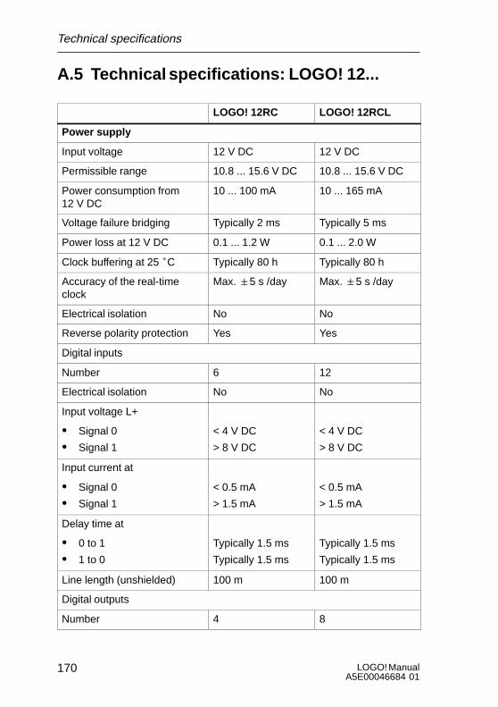
LOGO! ManualA5E00046684 01
170
A.5 Technical specifications: LOGO! 12...
LOGO! 12RC LOGO! 12RCL
Power supply
Input voltage 12 V DC 12 V DC
Permissible range 10.8 ... 15.6 V DC 10.8 ... 15.6 V DC
Power consumption from12 V DC
10 ... 100 mA 10 ... 165 mA
Voltage failure bridging Typically 2 ms Typically 5 ms
Power loss at 12 V DC 0.1 ... 1.2 W 0.1 ... 2.0 W
Clock buffering at 25 °C Typically 80 h Typically 80 h
Accuracy of the real-timeclock
Max. "5 s /day Max. "5 s /day
Electrical isolation No No
Reverse polarity protection Yes Yes
Digital inputs
Number 6 12
Electrical isolation No No
Input voltage L+
S Signal 0 < 4 V DC < 4 V DCg
S Signal 1 > 8 V DC > 8 V DC
Input current at
S Signal 0 < 0.5 mA < 0.5 mAg
S Signal 1 > 1.5 mA > 1.5 mA
Delay time at
S 0 to 1 Typically 1.5 ms Typically 1.5 ms
S 1 to 0
y y
Typically 1.5 ms
y y
Typically 1.5 ms
Line length (unshielded) 100 m 100 m
Digital outputs
Number 4 8
Technical specifications
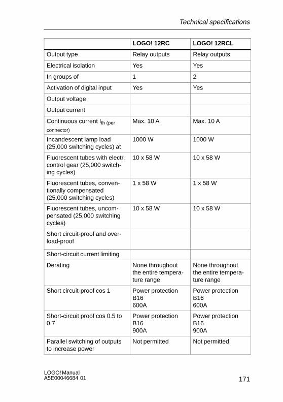
171LOGO! ManualA5E00046684 01
LOGO! 12RCLLOGO! 12RC
Output type Relay outputs Relay outputs
Electrical isolation Yes Yes
In groups of 1 2
Activation of digital input Yes Yes
Output voltage
Output current
Continuous current Ith (per
connector)
Max. 10 A Max. 10 A
Incandescent lamp load(25,000 switching cycles) at
1000 W 1000 W
Fluorescent tubes with electr.control gear (25,000 switch-ing cycles)
10 x 58 W 10 x 58 W
Fluorescent tubes, conven-tionally compensated(25,000 switching cycles)
1 x 58 W 1 x 58 W
Fluorescent tubes, uncom-pensated (25,000 switchingcycles)
10 x 58 W 10 x 58 W
Short circuit-proof and over-load-proof
Short-circuit current limiting
Derating None throughoutthe entire tempera-ture range
None throughoutthe entire tempera-ture range
Short circuit-proof cos 1 Power protectionB16600A
Power protectionB16600A
Short-circuit proof cos 0.5 to0.7
Power protectionB16900A
Power protectionB16900A
Parallel switching of outputsto increase power
Not permitted Not permitted
Technical specifications
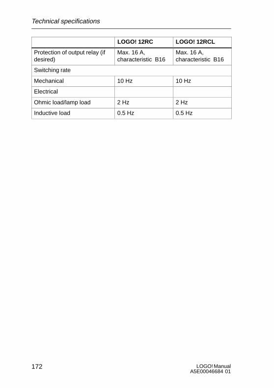
LOGO! ManualA5E00046684 01
172
LOGO! 12RCLLOGO! 12RC
Protection of output relay (ifdesired)
Max. 16 A,characteristic B16
Max. 16 A,characteristic B16
Switching rate
Mechanical 10 Hz 10 Hz
Electrical
Ohmic load/lamp load 2 Hz 2 Hz
Inductive load 0.5 Hz 0.5 Hz
Technical specifications
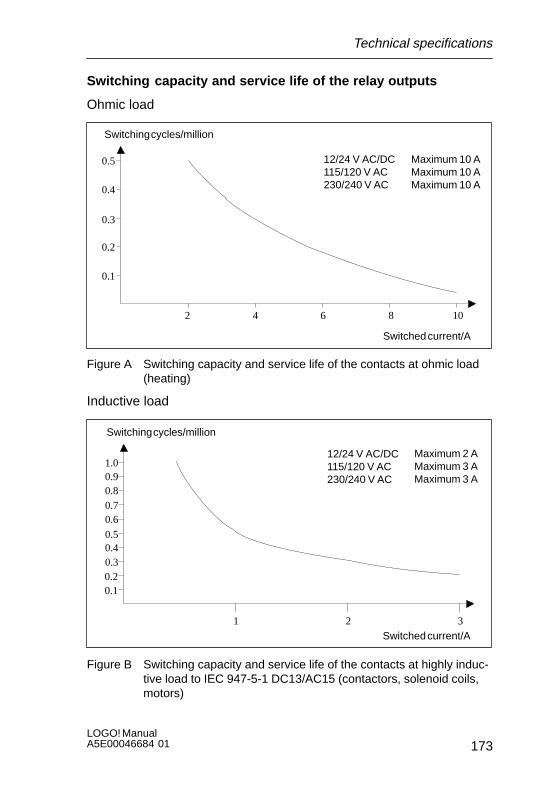
173LOGO! ManualA5E00046684 01
Switching capacity and service life of the relay outputs
Ohmic load
Switching cycles/million
Switched current/A
0.1
0.2
0.3
0.4
0.5
2 4 6 8 10
Maximum 10 AMaximum 10 AMaximum 10 A
12/24 V AC/DC115/120 V AC230/240 V AC
Figure A Switching capacity and service life of the contacts at ohmic load(heating)
Inductive load
Switching cycles/million
Switched current/A
0.10.20.30.40.5
321
0.60.70.80.91.0
Maximum 2 AMaximum 3 AMaximum 3 A
12/24 V AC/DC115/120 V AC230/240 V AC
Figure B Switching capacity and service life of the contacts at highly induc-tive load to IEC 947-5-1 DC13/AC15 (contactors, solenoid coils,motors)
Technical specifications
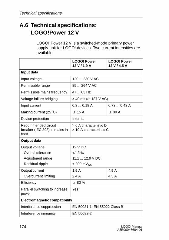
LOGO! ManualA5E00046684 01
174
A.6 Technical specifications: LOGO!Power 12 V
LOGO! Power 12 V is a switched-mode primary powersupply unit for LOGO! devices. Two current intensities areavailable.
LOGO! Power12 V / 1.9 A
LOGO! Power12 V / 4.5 A
Input data
Input voltage 120 ... 230 V AC
Permissible range 85 ... 264 V AC
Permissible mains frequency 47 ... 63 Hz
Voltage failure bridging > 40 ms (at 187 V AC)
Input current 0.3 ... 0.18 A 0.73 ... 0.43 A
Making current (25°C) v 15 A v 30 A
Device protection Internal
Recommended circuitbreaker (IEC 898) in mains in-feed
> 6 A characteristic D> 10 A characteristic C
Output data
Output voltage
Overall tolerance
Adjustment range
Residual ripple
12 V DC
+/- 3 %
11.1 ... 12.9 V DC
< 200 mVSS
Output current
Overcurrent limiting
1.9 A
2.4 A
4.5 A
4.5 A
Efficiency w 80 %
Parallel switching to increasepower
Yes
Electromagnetic compatibility
Interference suppression EN 50081-1, EN 55022 Class B
Interference immunity EN 50082-2
Technical specifications

175LOGO! ManualA5E00046684 01
LOGO! Power12 V / 4.5 A
LOGO! Power12 V / 1.9 A
Safety
Electrical isolation, primary/secondary
Yes, SELV (to EN 60950/VDE 0805)
Safety class II (to IEC 536/VDE 0106 T1)
Type of protection IP 20 (to EN 60529/VDE 470 T1)
CE marking
UL/CSA certification
FM approval
Yes
Yes UL 508 / CSA 22.2
In preparation
General details
Ambient temperature range –20 ... +55°C, natural convection
Storage and transport tem-perature
- 40 ... +70°C
Connections on input One connector (1x2.5mm2 o. 2x 1.5 mm2)each for L1 and N
Connections on output Two connectors (1x2.5mm2 o. 2x 1.5 mm2)each for L+ and M
Installation On 35 mm DIN rail, snap-on
Dimensions in mm (WxHxD) 72 x 80 x 55 126 x 90 x 55
Approx. weight 0.2 kg 0.4 kg
Technical specifications

LOGO! ManualA5E00046684 01
176
A.7 Technical specifications: LOGO!Power 24 V
LOGO! Power 24 V is a switched-mode primary powersupply unit for LOGO! devices. Two current intensities areavailable.
LOGO! Power24 V/1.3 A
LOGO! Power24 V/2.5 A
Input data
Input voltage 120 ... 230 V AC
Permissible range 85 ... 264 V AC
Permissible mains frequency 47 ... 63 Hz
Voltage failure bridging 40 ms (at 187 V AC)
Input current 0.48 ... 0.3 A 0.85 ... 0.5 A
Making current (25°C) < 15 A < 30 A
Device protection Internal
Recommended circuitbreaker (IEC 898) in mains in-feed
> 6 A characteristic D> 10 A characteristic C
Output data
Output voltage
Overall tolerance
Adjustment range
Residual ripple
24 V DC
+/- 3 %
22.2 ... 25.8 V DC
< 250 mVSS
Output current
Overcurrent limiting
1.3 A
1.6 A
2.5 A
2.8 A
Efficiency < 80 %
Parallel switching to increasepower
Yes
Electromagnetic compatibility
Interference suppression EN 50081-1, EN 55022 Class B
Interference immunity EN 50082-2
Technical specifications
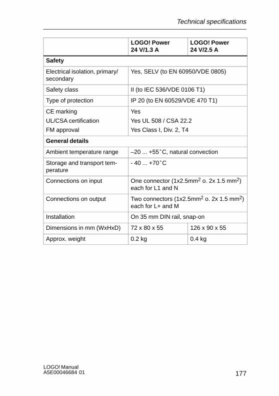
177LOGO! ManualA5E00046684 01
LOGO! Power24 V/2.5 A
LOGO! Power24 V/1.3 A
Safety
Electrical isolation, primary/secondary
Yes, SELV (to EN 60950/VDE 0805)
Safety class II (to IEC 536/VDE 0106 T1)
Type of protection IP 20 (to EN 60529/VDE 470 T1)
CE marking
UL/CSA certification
FM approval
Yes
Yes UL 508 / CSA 22.2
Yes Class I, Div. 2, T4
General details
Ambient temperature range –20 ... +55°C, natural convection
Storage and transport tem-perature
- 40 ... +70°C
Connections on input One connector (1x2.5mm2 o. 2x 1.5 mm2)each for L1 and N
Connections on output Two connectors (1x2.5mm2 o. 2x 1.5 mm2)each for L+ and M
Installation On 35 mm DIN rail, snap-on
Dimensions in mm (WxHxD) 72 x 80 x 55 126 x 90 x 55
Approx. weight 0.2 kg 0.4 kg
Technical specifications
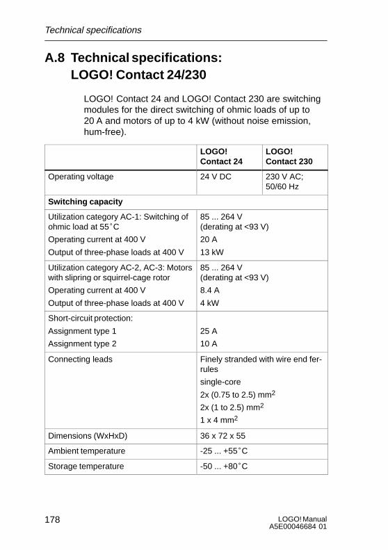
LOGO! ManualA5E00046684 01
178
A.8 Technical specifications: LOGO! Contact 24/230
LOGO! Contact 24 and LOGO! Contact 230 are switchingmodules for the direct switching of ohmic loads of up to20 A and motors of up to 4 kW (without noise emission,hum-free).
LOGO! Contact 24
LOGO! Contact 230
Operating voltage 24 V DC 230 V AC;50/60 Hz
Switching capacity
Utilization category AC-1: Switching ofohmic load at 55°C
Operating current at 400 V
Output of three-phase loads at 400 V
85 ... 264 V(derating at <93 V)
20 A
13 kW
Utilization category AC-2, AC-3: Motorswith slipring or squirrel-cage rotor
Operating current at 400 V
Output of three-phase loads at 400 V
85 ... 264 V(derating at <93 V)
8.4 A
4 kW
Short-circuit protection:
Assignment type 1
Assignment type 2
25 A
10 A
Connecting leads Finely stranded with wire end fer-rules
single-core
2x (0.75 to 2.5) mm2
2x (1 to 2.5) mm2
1 x 4 mm2
Dimensions (WxHxD) 36 x 72 x 55
Ambient temperature -25 ... +55°C
Storage temperature -50 ... +80°C
Technical specifications

179LOGO! ManualA5E00046684 01
B Determining memory require-ments
Use of memory areas
If you are unable to enter another block when you are en-tering a program, this means a memory area is completelyoccupied. LOGO! only offers you the blocks that will still fitinto LOGO!. If no more blocks from a list fit into LOGO!,you will not be able to select the list again.
If a memory area is occupied, you have to optimize yourcircuit or use a second LOGO!.
Determining the amount of memory required
When you calculate the memory requirements of a circuit,you must always include all the individual areas of thememory.
Example:
Q1xI2
B01B02
B03
x
B04
0 0006 002
No 1No 2No 3
I1T
B05B06
T Q2
I3I4x
Par RAM REMTimerPar RAM REMTimer
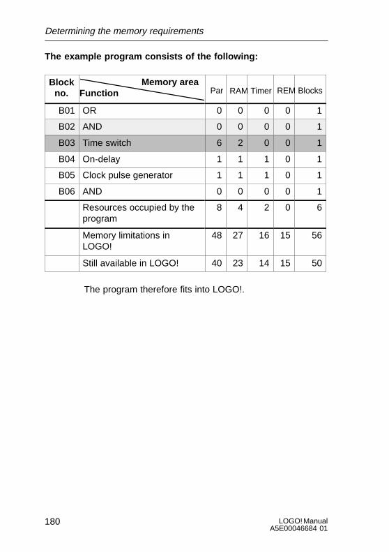
LOGO! ManualA5E00046684 01
180
The example program consists of the following:
Blockno. Function
Memory areaPar RAM Timer REM Blocks
B01 OR 0 0 0 0 1
B02 AND 0 0 0 0 1
B03 Time switch 6 2 0 0 1
B04 On-delay 1 1 1 0 1
B05 Clock pulse generator 1 1 1 0 1
B06 AND 0 0 0 0 1
Resources occupied by theprogram
8 4 2 0 6
Memory limitations inLOGO!
48 27 16 15 56
Still available in LOGO! 40 23 14 15 50
The program therefore fits into LOGO!.
Determining the memory requirements
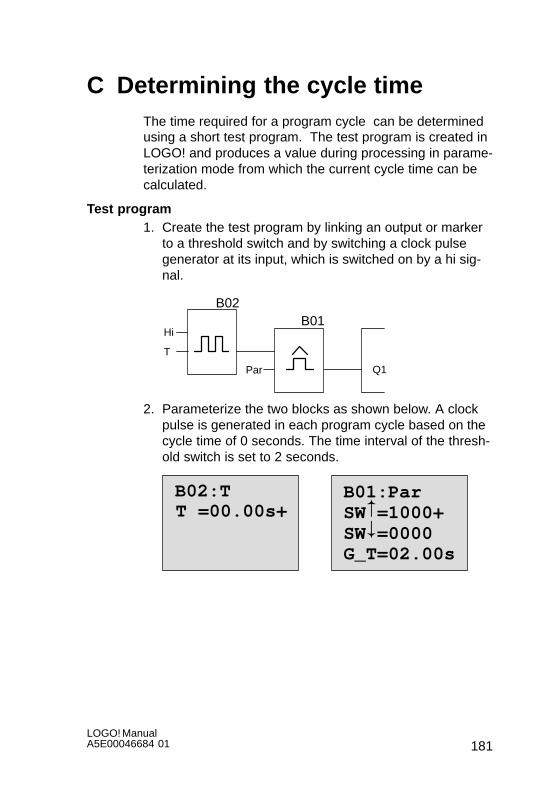
181LOGO! ManualA5E00046684 01
C Determining the cycle timeThe time required for a program cycle can be determinedusing a short test program. The test program is created inLOGO! and produces a value during processing in parame-terization mode from which the current cycle time can becalculated.
Test program1. Create the test program by linking an output or marker
to a threshold switch and by switching a clock pulsegenerator at its input, which is switched on by a hi sig-nal.
Hi
Par Q1
T
B02B01
2. Parameterize the two blocks as shown below. A clockpulse is generated in each program cycle based on thecycle time of 0 seconds. The time interval of the thresh-old switch is set to 2 seconds.
B02:TT =00.00s+
B01:ParSW =1000+SW =0000G_T=02.00s
#"
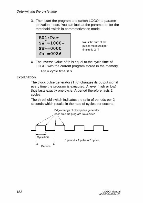
LOGO! ManualA5E00046684 01
182
3. Then start the program and switch LOGO! to parame-terization mode. You can look at the parameters for thethreshold switch in parameterization mode.
B01:ParSW =1000+SW =0000fa =0086
#" fa= is the sum of the
pulses measured pertime unit G_T
4. The inverse value of fa is equal to the cycle time ofLOGO! with the current program stored in the memory.
1/fa = cycle time in s
Explanation
The clock pulse generator (T=0) changes its output signalevery time the program is executed. A level (high or low)thus lasts exactly one cycle. A period therefore lasts 2cycles.
The threshold switch indicates the ratio of periods per 2seconds which results in the ratio of cycles per second.
Edge change of clock pulse generatoreach time the program is executed
Cycle time
Periods
1 period = 1 pulse = 2 cycles
Determining the cycle time

183LOGO! ManualA5E00046684 01
D LOGO! without display The LOGO! 24RCo and LOGO! 230RCo variants without adisplay were developed because some special applicationsdon’t need operating units such as keypads and a displayduring operation.
I4 I5 I6
Q1 Q2 Q3 Q4
SIEMENS
I1 I2 I31 L N
RUN/STOP
LOGO! 230RC0
Output 4 x relay/10A
Less is definitely more!
The advantages for you:S More cost-efficient than with an operating unit.S Require less space in the cabinet than conventional
hardware.S Considerably more flexible and less costly than sepa-
rate hardware units.S Advantageous for applications in which two or three
conventional switching devices can be replaced.S Very easy to use.S Cannot be used by unauthorized persons.S Compatible with LOGO! basic variants.

LOGO! ManualA5E00046684 01
184
Programming without an operating unit
There are two ways to program LOGO! without a display:S Create a program with LOGO! software on the PC and
transfer the program to LOGO!S Transfer the program from a LOGO! program module/
card to your LOGO! without a display.
Operating characteristics
Once the power supply has been connected, LOGO! isready for operation. You can switch off LOGO! without adisplay by disconnecting the power supply, for example byremoving the plug.
You can’t use a key combination to set up LOGO! RCo var-iants for data transfer, and similarly programs can’t bestopped or started using keys. LOGO! RCo variants there-fore have modified startup characteristics:
Startup characteristics
If a LOGO! program module/card is inserted, a programstored there will be copied to the device immediately afterLOGO! has been switched on, thus overwriting an existingprogram.
If a PC cable is inserted, LOGO! automatically goes intoPC ´ LOGO mode when it is switched on. Using the PCsoftware LOGO!Soft and LOGO!Soft Comfort you can readthe programs from LOGO! or store them on LOGO!.
If there is already a valid program in the program memory,LOGO! will automatically transfer from STOP to RUN afterpower has been switched on.
LOGO! without display

185LOGO! ManualA5E00046684 01
Operating status indicator
Operating statuses, such as Power On, RUN and STOPare indicated by an LED on the front hood.S Red LED: PowerOn/STOPS Green LED: PowerOn/RUN
After the power supply has been switched on and when-ever LOGO! is not in RUN mode, the red LED comes on.When LOGO! is in RUN mode, the green LED comes on.
LOGO! without display
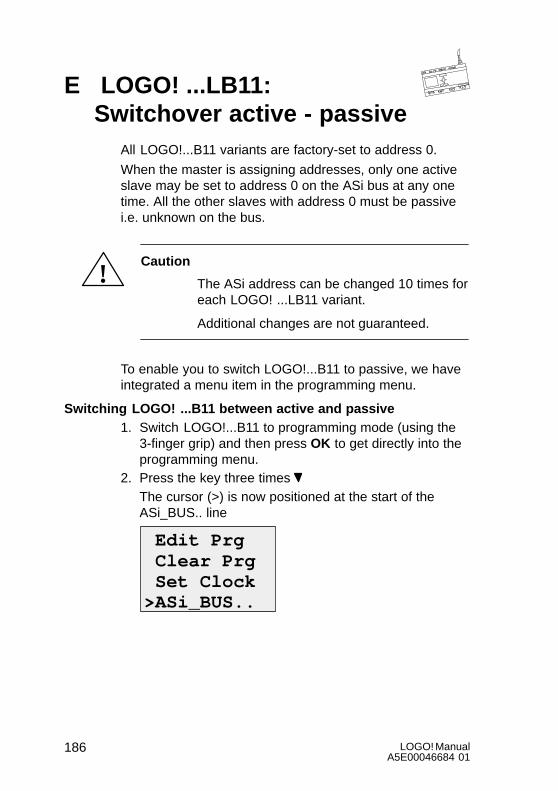
LOGO! ManualA5E00046684 01
186
E LOGO! ...LB11: Switchover active - passive
All LOGO!...B11 variants are factory-set to address 0.
When the master is assigning addresses, only one activeslave may be set to address 0 on the ASi bus at any onetime. All the other slaves with address 0 must be passivei.e. unknown on the bus.
!Caution
The ASi address can be changed 10 times foreach LOGO! ...LB11 variant.
Additional changes are not guaranteed.
To enable you to switch LOGO!...B11 to passive, we haveintegrated a menu item in the programming menu.
Switching LOGO! ...B11 between active and passive1. Switch LOGO!...B11 to programming mode (using the
3-finger grip) and then press OK to get directly into theprogramming menu.
2. Press the key three times The cursor (>) is now positioned at the start of theASi_BUS.. line
Edit Prg Clear Prg Set Clock>ASi_BUS..

187LOGO! ManualA5E00046684 01
3. Press OK. The following display appears:
> Active PassiveLOGO: Active
4. Switch LOGO!...B11 to passive by pressing the key and then OK. The display indicates the new state
LOGO: Passive
5. As soon as the master has recognized an active slaveand assigned it an address, you can switch anotherslave back from passive to active .
Note
You can only exit the menu for switching between activeand passive if LOGO! is switched to active .
LOGO! ...B11: SwitchoverActive- passive
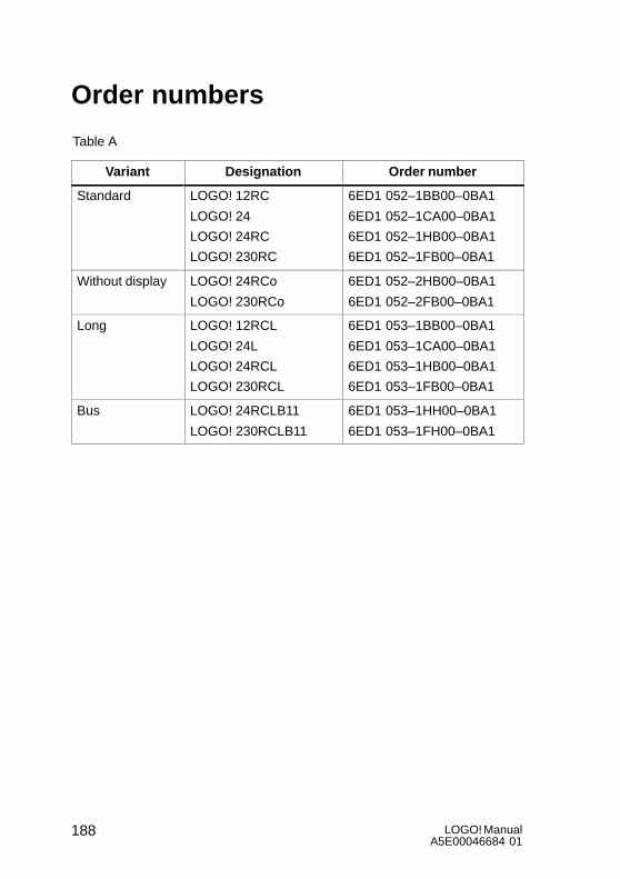
LOGO! ManualA5E00046684 01
188
Order numbers
Table A
Variant Designation Order number
Standard LOGO! 12RC
LOGO! 24
LOGO! 24RC
LOGO! 230RC
6ED1 052–1BB00–0BA1
6ED1 052–1CA00–0BA1
6ED1 052–1HB00–0BA1
6ED1 052–1FB00–0BA1
Without display LOGO! 24RCo
LOGO! 230RCo
6ED1 052–2HB00–0BA1
6ED1 052–2FB00–0BA1
Long LOGO! 12RCL
LOGO! 24L
LOGO! 24RCL
LOGO! 230RCL
6ED1 053–1BB00–0BA1
6ED1 053–1CA00–0BA1
6ED1 053–1HB00–0BA1
6ED1 053–1FB00–0BA1
Bus LOGO! 24RCLB11
LOGO! 230RCLB11
6ED1 053–1HH00–0BA1
6ED1 053–1FH00–0BA1
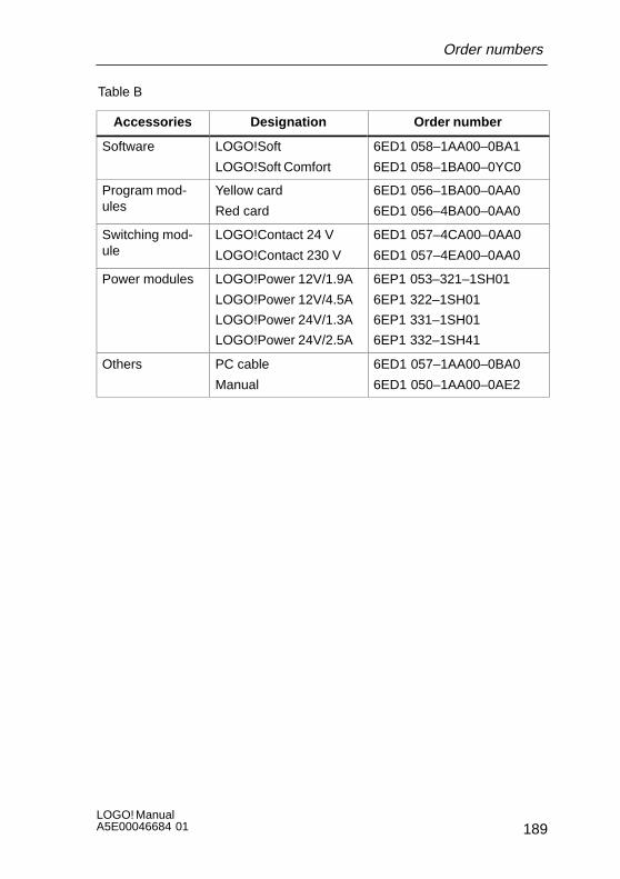
189LOGO! ManualA5E00046684 01
Table B
Accessories Designation Order number
Software LOGO!Soft
LOGO!Soft Comfort
6ED1 058–1AA00–0BA1
6ED1 058–1BA00–0YC0
Program mod-ules
Yellow card
Red card
6ED1 056–1BA00–0AA0
6ED1 056–4BA00–0AA0
Switching mod-ule
LOGO!Contact 24 V
LOGO!Contact 230 V
6ED1 057–4CA00–0AA0
6ED1 057–4EA00–0AA0
Power modules LOGO!Power 12V/1.9A
LOGO!Power 12V/4.5A
LOGO!Power 24V/1.3A
LOGO!Power 24V/2.5A
6EP1 053–321–1SH01
6EP1 322–1SH01
6EP1 331–1SH01
6EP1 332–1SH41
Others PC cable
Manual
6ED1 057–1AA00–0BA0
6ED1 050–1AA00–0AE2
Order numbers
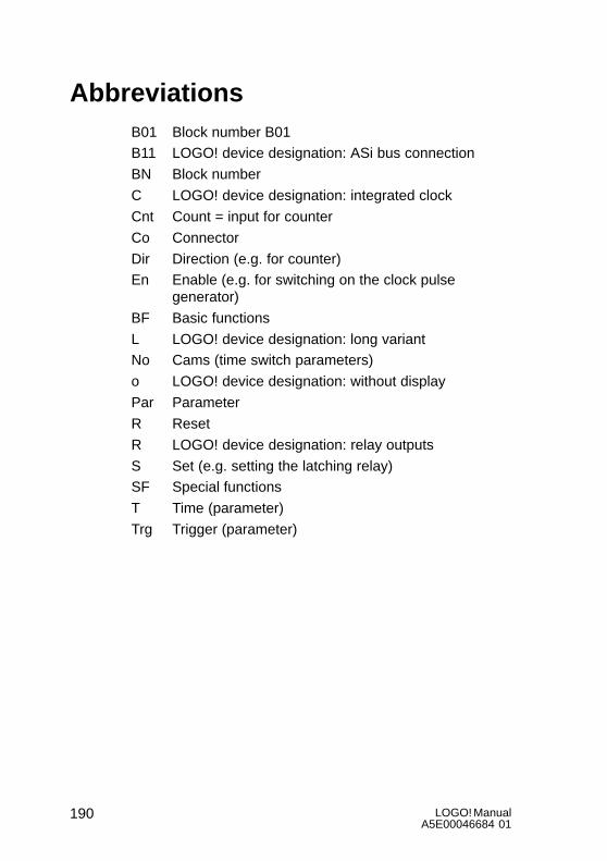
LOGO! ManualA5E00046684 01
190
AbbreviationsB01 Block number B01B11 LOGO! device designation: ASi bus connection
BN Block number
C LOGO! device designation: integrated clock
Cnt Count = input for counter
Co Connector
Dir Direction (e.g. for counter)En Enable (e.g. for switching on the clock pulse
generator)
BF Basic functions
L LOGO! device designation: long variantNo Cams (time switch parameters)
o LOGO! device designation: without display
Par Parameter
R Reset
R LOGO! device designation: relay outputs
S Set (e.g. setting the latching relay)SF Special functions
T Time (parameter)
Trg Trigger (parameter)
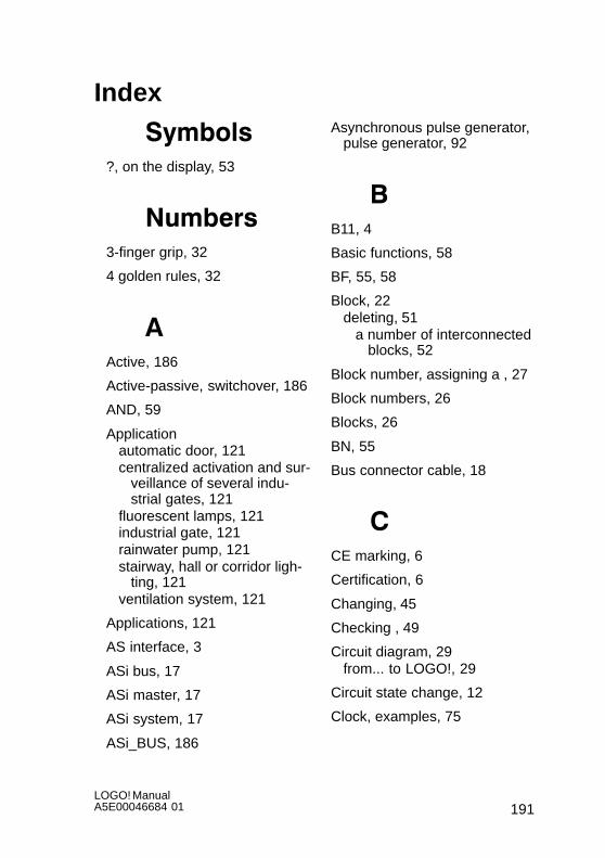
191LOGO! ManualA5E00046684 01
Index
Symbols?, on the display, 53
Numbers3-finger grip, 32
4 golden rules, 32
AActive, 186
Active-passive, switchover, 186
AND, 59
Applicationautomatic door, 121centralized activation and sur-
veillance of several indu-strial gates, 121
fluorescent lamps, 121industrial gate, 121rainwater pump, 121stairway, hall or corridor ligh-
ting, 121ventilation system, 121
Applications, 121
AS interface, 3
ASi bus, 17
ASi master, 17
ASi system, 17
ASi_BUS, 186
Asynchronous pulse generator,pulse generator, 92
BB11, 4
Basic functions, 58
BF, 55, 58
Block, 22deleting, 51
a number of interconnectedblocks, 52
Block number, assigning a , 27
Block numbers, 26
Blocks, 26
BN, 55
Bus connector cable, 18
CCE marking, 6
Certification, 6
Changing, 45
Checking , 49
Circuit diagram, 29from... to LOGO!, 29
Circuit state change, 12
Clock, examples, 75
LOGO! ManualA5E00046684 01
192
Clock pulse generator, symme-trical, 79
Co, 55, 56
Connecting, outputs, 15
Connector, 22
Connector X, 65
Connectors, 24hi, 25inputs, 25lo, 25LOGO!’s, 25outputs, 25x, 25
Connectors , 56
Constants, 56
Control panel, 3
Control program, 95
Correcting typing errors,53
CSA, 6
Current impulse relay, 71
Cursor, 33
Cursor movement, 33
Cycle time, 181
DDay of the week, 73
Deleting, a program, 54
Device types, LOGO!, 2
Diagram overview, 28
Dimensions, 7of instalIation equipment, 7
DIN rail, 7
Display, LOGO!’s, 27
Display image, 27
Displaying, 49
drag and drop, 116
EEditing, 46
Entering the program, example,38
Example, entering the program,38
Exiting programming mode, 49
FFast inputs, 12
FM, 6
Frequency functions, 12
Functions, 55
GGetting to know LOGO! , 1
Golden rules, 32
Ground terminal, 10
HHiding, 49
Index
193LOGO! ManualA5E00046684 01
IInputs, 56
Inserting, 46
Inserting a block, 46
Inserting the program module/card, 110
Installation, 17
Installing and wiring LOGO!, 7
Internet address, 121
Interval time-delay relay, 86
LLatching relay, 77
LCD, 3
LED, 185
Levels, 57
Limitations, 95
ListBF, 55BN, 55Co, 55SF, 55
Lists, 55
Logic module, 1
LOGO!, 22, 99, 107connecting to a PC, 118deinstalling, 8installing, 7, 8operating statuses, 21recognizing, 4structure of, 3
switching on, 19variants, 5wiring, 9
LOGO! software, 115installation, 117
LOGO! symbols, 4
LOGO!...LB11, on the ASi bus,18
LOGO!’s inputs, connecting, 11
LOGO!’s menu, 34
LOGO!Soft, 20, 116
LOGO!Soft Comfort, 20, 116
MMarkers, 56
Memory, 96
Memory area, 95
Memory required, 95
Memory requirements, 179
Modeparameterization, 100parameterizing, 34programming, 34
Modules, 7
NNAND, 61
Nesting depth, 95, 97
NOR, 61
Index
LOGO! ManualA5E00046684 01
194
NOT, 60
OOff time, 74
Off-delay, 69
On time, 74
On-delay, 67retentive, 81
Open connectors, 57
Operating characteristics, 184
Operating hours counter, 83
Operating mode PC´LOGO,118
Operating status indicator, 185
Operation, 117
OR, 59
Outputs, 56connecting, 15
PPar, 95
Parameterdisplaying/hiding, 49selecting, 101setting, 99T, 63
Parameter window, 73
Parameterizing, 48
Parameters, changing, 102
Passive, 186
passive, 186
PC cable, 118
PC´LOGO, 118
Planning, 33
Power off, 19
Power on, 19
Power supply, connecting, 9
Power switch, 19
Program cycle, 181
Program module, 20inserting, 109red, copy protection feature,
know-how protection, 107removing, 109yellow, copying, 107
Program path , 97
Programm, deleting, 54
Programsachiving, 107duplicating, 107sending by post, 107
Pulse duration , 92
pulse interval, 92
RRAM, 95
Relay output, LOGO! with, 5
Relay outputs, 73prerequisites, 15service life, 173switching capacity, 173
Index

195LOGO! ManualA5E00046684 01
REM, 95
Removing the module, 110
Reset, 65
Reset input , 65
Resources, 95
Resumption of power, 19
Retentive on-delay, 81, 93
Retentivity, 64
Rules, 4 golden, 32
RUN, 42switching to ... , 42
SSensor attributes, for LOGO!,
11
Setting, 48the time, 105
Seven-day time switch, 4
SF, 55, 63
Size of a circuit, 95
Slave, 4
Special functions, 63
Startup characteristics, modi-fied, 184
Summer time, 106
Switched current, maximum, 16
Switching, summer and wintertime, 106
Switchover, active–passive,186
Symmetrical clock pulse gene-rator, 79
TT. See time
Technical specifications, 159general, 159LOGO! 12RC, LOGO!
12RCL, 170LOGO! 230...., 161LOGO! 24, LOGO! 24RC,
LOGO! 24RCo, 164LOGO! 24L, LOGO! 24RCL,
LOGO! 24RCLB11, 167LOGO!Contact 24,
LOGO!Contact 230, 178LOGO!Power 12 V, 174LOGO!Power 24 V, 176
Terminal block, 97
Threshold switch, 90
Timeaccuracy of the , 63setting, 105
Time error, 63
Time switch, 1, 72, 74setting, 74
Timer, 95
Transistor output, LOGO! with,5
Transistor outputs, 16
Index

LOGO! ManualA5E00046684 01
196
Two-wire lead, 17
Type of protection, 49, 66
UUL, 6
Up/Down Counter, 87
Upward compatibility, 109
VVoltage levels, 57
WWinter time, 106
Wire end ferrules, 9
Without display, 183
XXOR, 62
YYear 2000, millennium, 63
Index