Embed Size (px)
Citation preview

www.siemens.com/plm/fibersim
FIBERSIMEngineering innovative, durable and lightweight composite structures
Siemens PLM Software

2
Fibersim software:
• Supports multiple composite design and manufacturing processes
• Automates design definition and change
• Open architecture supports multiple CAD systems and best-in-class engineering tools

3
Contents
A specialized problem requires specialized tools 5
Addressing the unique needs of collaborative composite product development 6
Supporting the entire composite product development process 7
Preliminary design 8
Ply/core development 10
Detailed design definition 12
Verify design data 13
Product producibility simulation 14
Manufacturing definition 15
Manufacturing design detail 16
Manufacturing documentation and automation 17
Product inspection 18
Integrate the entire composite development process 19

4
Composite designs are developed from unstructured information, including spec-ifications, standards, attributes and requirements. A single composite part is made up of tens to thousands of unique objects, including plies, core and inserts that must accurately reflect that informa-tion in an iterative design-to-manufactur-ing process. The tasks necessary to define and share this information are both tedious and complex. Such tasks are often not automated or well supported by commercial 3D CAD systems, making them more prone to error. You must accurately interpret and apply specifica-tions or standards, and validate that they meet requirements in order to success-fully certify and produce a composite
product. This complexity, along with increasing market demand for innovative composite products that weigh less, cost less and are delivered faster puts an enor-mous demand on you and your software systems. So it is critical to have special-ized tools that reflect the unique compos-ite terminology and processes used by your industry to develop products that efficiently meet those demands.
That’s exactly what Fibersim™ software from Siemens PLM Software provides: Specialized solutions for developing high quality composite products efficiently and profitably.
4
5
A specialized problem requires specialized tools
Composite design, analysis and manu-facturing is complex, specialized work that can best be performed if engineers possess tools that allow them to work how they think with a variety of param-eters, including material type, fiber ori-entation, stack-up order, balance, sym-metry, drop-offs, splices and darts. For this nongeometric information to be useful in the product development pro-cess, it must create or be associative to geometry so you can view and edit it simultaneously. And to be competitive you must eliminate painstaking manual creation and management of individual attributes or specifications for tens to thousands of material layers in order to rapidly deliver high performance products.
Let’s first consider the composite design phase. Composite design meth-ods are specialized for an industry and product, demanding specific approaches that accurately capture engineering requirements and provide automated tools for creating designs. Whether engineering requirements are based on structural analysis or design for manufacturing, data needs to be accurately and easily captured because attempting to manually create compos-ite laminates that meet specifications istedious, error-prone and time- consuming.
Composite analysis processes are also specialized. Currently, parts are often overbuilt due to the ambiguities in product development and manufactur-ing. Collaboration between engineer-ing, manufacturing and analysis is required in order to optimize products and exceed performance, weight and cost targets. Analysts must communi-cate and receive unambiguous feed-back about desired fiber orientations and manufacturing process limitations.
And composites manufacturing pro-cesses are complex and specialized as well. Only by instituting consistent and repeatable manufacturing processes can a company achieve the goals of reducing composite product costs while enhancing quality and through-put. To do this, manufacturing engi-neers need an accurate and efficient way to consume the engineering prod-uct definition. This demands an auto-mated link between the design, analy-sis and manufacturing definitions and the systems used in production.
Fibersim composites engineering soft-ware from Siemens PLM Software spe-cifically addresses these challenges by providing an intelligent design-to-man-ufacturing composite product develop-ment solution that is fully integrated into commercial 3D CAD systems –resulting in products optimized for performance, cost, quality and throughput. The software allows for industry- and part-specific composite development processes that create innovative products that are used from the far reaches of space to the depths of the ocean. It does this by supporting digital, model-based processes that enable optimization, increased effi-ciency and reduced errors. In addition, Fibersim facilitates collaboration between design, analysis and manufac-turing. And its open architecture allows you to develop best-in-class solutions tailored to your product and process and to share essential information among cross-discipline product devel-opment teams. Fibersim provides the specialized tools you need to success-fully deliver innovative, lightweight composite structures.

6
For design engineers, Fibersim facilitates the authoring of composite design data to create a complete 3D product defini-tion. Composite specifications, require-ments and intent are associatively linked to the geometry in the 3D CAD model. It provides tools for automating repeti-tive design tasks, such as applying mate-rial requirements and creating ply geom-etry. This helps you manage design changes during iterative feedback loops with analysis and manufacturing. In addi-tion, the software automates varying lev-els of visual and data representations to best suit the immediate engineering task and generates a variety of deliverables, such as design documentation, model-based definition formats and enterprise reports.
For analysts, Fibersim facilitates compos-ite product optimization by enabling bi‐directional communication between disciplines. Analysts understand that to achieve the full benefit of composites they must define fiber orientations that provide the greatest structural benefit, but they are limited by material and manufacturing parameters. The software allows analysts to communicate the desired fiber orientations to the design and manufacturing engineers and pro-vides feedback to the analyst, including achievable fiber orientations based on the material and process. This results in products that achieve the highest level of part performance and optimization.
For manufacturing engineers, Fibersim facilitates the creation, management and communication of the manufacturing definition by consuming the design data and generating an associative manufac-turing model. The software provides tools that automate design for manufac-turing, such as splicing, darting and ply edge adjustments for automated deposi-tion based on simulation of the manufac-turing process, machine characteristics and materials. It ensures quality compos-ite products by automating the creation of documentation and manufacturing data for nesting, cutting, laser projection, tape laying, fiber placement and inspec-tion. And it communicates the effects of design changes to the manufacturing definition, automatically updating all manufacturing data.
The result is an efficient process for delivering optimized composite products.
Addressing the unique needs of collaborative composite product development

7
Supporting the entire composite development process
Engineering kickoffInputs: Lofted surfaces, material specifica-tions, design specifications, manufacturing processes
Preliminary design
Ply/core development
Detailed design definition
Verify design data
Product producibility simulation
Manufacturing definitionManufacturing design detail
Engineering release
Manufacturing documentionand automation
Product inspection
DeliveryOn timeOn budgetOn specification
Opt
imiz
e / i
tera
te
Desi
gnM
anuf
actu
ring
7

8
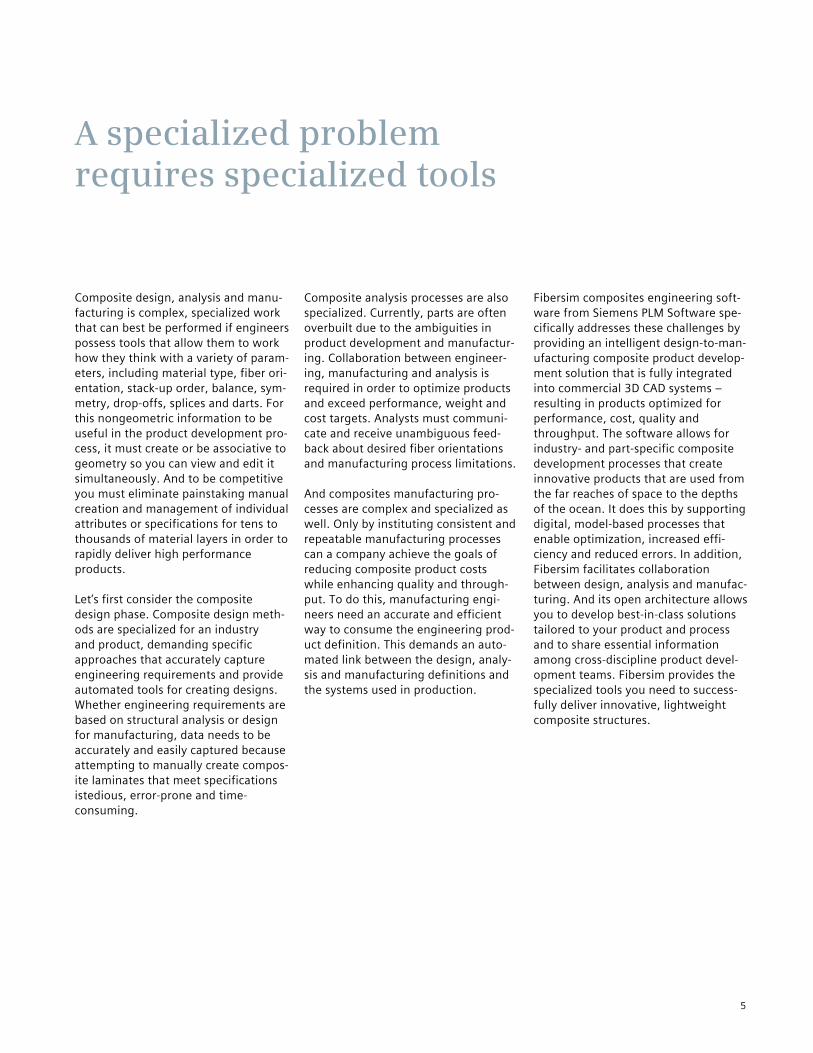
Traditionally, the preliminary design process entailed a time-consuming exchange of documents multiple times between the designer and analyst to agree on an initial optimized part definition.
Engineers can now use Fibersim Analysis Interface™ to rapidly import the CAE model data directly into Fibersim to help design the part in the CAD system. Fibersim Analysis Interface also enables export of detailed design data back to CAE software for more accurate part analysis.
While Fibersim has many tools to assist the designer in achieving the initial design specifications provided by the analyst, the final design may still differ significantly from the idealized part that was analyzed. For example, the final design may contain additional plies that were not considered in the original analysis. Prior to the existence of Fibersim Analysis Interface, the true performance of the final part was therefore never precisely known.
The Fibersim Analysis Interface addresses this problem by enabling engineers to design a composite part in the CAD sys-tem, determine the state of the manufac-tured part using simulation technology, and then use the as‐manufactured defini-tion as input into the CAE system for vali-dation analysis.
Closing the loop between the Fibersim designer and the CAE analyst allows com-panies to eliminate the practice of part overdesign that so often defeats the orig-inal purpose of using composites in the first place.
Preliminary design
Key functionality
• Ply data export to CAE software, including true fiber orientations that result from Fibersim producibility simulation
• Ply data import from CAE software, including ply shapes and specified orientations
• Core data exchange• Zone data exchange, including
laminate specifications
Benefits
• Optimized design resulting from more design and analysis iterations completed in less time
• Reduction in time wasted on clarifying communication and correcting errors
• Improved design reliability based on more accurate failure and durability analysis
• Less overdesign and better control over margins of safety and part performance assessment
Closing the loop between composites design and analysis
9
The Fibersim Analysis Interface drives analysis from the same single CAD master model that is used for design and manufacturing. This permits analysis to be performed on a part in its to‐be-manufactured state.

10
Efficient and accurate development of plies or cores requires a deep under-standing of the collaborative design pro-cesses of composite products. Based on 20 years of experience in commercial aerospace, automotive, defense, marine, wind energy and others industries, we understand that a “one size fits all” approach doesn’t work for composite design processes. Fibersim open architec-ture allows for sharing data in cross- discipline teams in the most appropriate manner for your industry and product.
For example, an aerospace wing skin panel, automotive B-pillar, wind turbine blade and jet engine fan blade all require an efficient and automated composite product development approach within a 3D CAD environment. Fibersim facilitates this by providing:
• Structure-based design that supports commercial aerospace wing skin panel processes in which development is based on material requirements defined by analysis and ply relation-ships to the mating substructure
• Analysis or Excel ply imports supporting automotive B-pillar process in which development is based on rapid iterations that balance product geometry and structural performance
• Wind blade design that supports the turbine blade development process in which blade shells are developed based on preliminary design data and material location with respect to the blade spine, root and tip
• Volume fill that supports jet engine fan blade product development processes based on material requirements defined by analysis and filling the volume between high-pressure and low- pressure aerodynamic surfaces.
Supporting rapid changes during design requires consistently defining and man-aging up to 150 attributes, such as mate-rial type, mechanical properties, orienta-tion, width, thicknesses, weight, cost and layup order. Keeping up with this during the iterative development cycle is tedious and error-prone. Fibersim ensures accu-racy by generating attributes during development and provides organization and modification capabilities en masse. The management capabilities and materi-als database ensure that attributes are assigned consistently across an organization.
Ply/core development
Key functionality
Industry- and product-specific composite ply and core develop-ment processes, including:
• Material requirement and ply import
• Ply design• Zone and grid design• Structure-based design• Wind blade design import• Volume fill
Benefits
• Enriches industry- and product-specific product development processes
• Reduces ply development time by as much as 80 percent
• Provides collaborative and rapid iterations between cross-discipline product development teams
• Promotes data re-use from specialized tools used by other disciplines, eliminating ply and core development errors
Efficiently developing plies and core with product-specific automated processes

11
Fibersim zone-based capability defines material specifications for specific areas of the part called zones. Zones highlight-ed in Fibersim are displayed within the CAD model in a user-defined color with text in-dicating the zone name, zone thickness, number of plies and specification.
Fibersim Excel import capability creates all of the plies from the imported Excel spreadsheet containing ply names, materials, orientations and CAD ply bound-ary name. Plies highlighted in Fibersim are displayed in the CAD model. Plies are indicated by blue-0°, green-45°, yellow-90°, red-45°.

12
Myriad engineering specifications and standards dictate detailed design defini-tion, including drop-off locations and profiles, ply corner treatments and fea-ture or component relationships. Iterative changes that occur throughout the development process make it extremely difficult to ensure adherence.Fibersim helps you adhere to engineering requirements by incorporating specifica-tions and standards into the design, including ply drop-offs, stagger profiles, stacking and more, which automate cre-ation of design details and associated geometry, such as ply boundaries and offset surfaces.
You must manage assembly component and composite feature relationships to ensure engineering requirements are met. For example, specifications may
require ply drop-offs to be offset or cross-ing mating components in a specific manner. Fibersim directly incorporates these relationships to ensure adherence to specifications.
Due to the vast number of composite features, it is easy to inadvertently vio-late standards and specifications during change processes. Fibersim removes the risk of error and reduces tedium by iden-tifying affected features and modifying attributes or associated geometry. With Fibersim, you can modify the specifica-tions or standards and leave the modifi-cation of affected composite features and geometry to the software.
Detailed design definition
Key functionality
• Ply drop-off• Stagger profile• Offset specification• Stagger editor• Ply corner treatment Benefits
• Reduces detailed design cycle time
• Eliminates interpretation and errors relating to the engineering specifications and standards
• Improves design change cycle times by up to 90 percent
• Reduces engineering change orders resulting from violations of engineering specifications
Fibersim zone transitions provide an automated way to create the desired drop-off profile by either using stagger shapes or dragging and dropping plies to the appropriate ply boundary.
Modifying ply corners is as simple as selecting the desired chamfer or shape in Fibersim using its intuitive interface that immediately updates ply boundaries.
Automating detailed design by incorporating engineering specifications and standards

13
Design verification is critical in a collabor-ative product development process. Design changes to the standards, specifi-cations and attributes pose risks to fulfill-ing product requirements and meeting targets. Review of each aspect requires visibility into the composite features, laminate and assembly relationships.Engineering documentation brings visibil-ity to the composite details during verifi-cation, including drop-off profiles, ply order and ply materials. Fibersim helps automate the creation of cross sections, annotations and core samples that are updatable as changes occur, ensuring the design is accurately reflected. Fibersim core sampling capabilities provide deeper details, such as ply thickness changes, fiber deviation, balance and symmetry, which are invaluable in ensuring product quality.
Understanding laminate weight and cost is critical to making go/no-go decisions during verification. Fibersim instantly provides the laminate weight and cost, including post cure processes, to provide the most accurate information during review.
Assembly relationships such as packaging and clash detection are an important aspect of design verification as well. Fibersim automatically creates surface and solid representations that allow you to detect clash between assembly compo-nents and ensure that packaging require-ments are met.
Verify design data
Key functionality
Automate the creation of com-posite engineering documenta-tion and laminate representa-tions for design verification, including:
• Analysis interface• Annotations including:
> Core sample > Ply table > Material table > Ply callout > Cross sections > Stepped solid > Zone solid
Benefits
• Reduces time to create engineering documentation
• Ensures accurate, up-to-date documentation
• Eliminates errors associated with manual creation of engineering documentation
• Ensures accurate solid and surface composite part representations
Verifying designs with automated documentation
Fibersim cross sections are automatically created with a pushbutton operation and are associative to the design, eliminating manual effort and ensuring accuracy.
Fibersim exploded laminate and annotation capabilities provide an instantaneous method for creating surface representations of the stack-up and annotations that are up-datable as the design changes. Plies are indicated by blue-0°, green-45°, yellow-90°, red-45°.

14
Knowing how materials conform to part shapes during manufacturing is crucial to producing high quality composite prod-ucts. Fibersim provides unparalleled capabilities to help you balance material, shape and manufacturing process deci-sions to create optimized products.
Fibersim allows you to simulate materi-als, such as woven fabrics, uni-directional tape, tow and multi-axial fabrics, with respect to the manufacturing process, such as hand or multi-stage layup, fiber steering, forming and automated fiber placement or tape laying. Uniquely, the simulation uses the actual 3D part geom-etry to provide the most accurate feed-back. Simulations can be done ply-by-ply or en masse, providing rapid feedback via a color mapped visualization that dis-plays where fiber deformation or devia-
tion, shearing and fiber buckling exceed acceptable limits. True fiber orientations can be passed to CAE software so ana-lysts can optimize parts.
Automated tape laying and fiber placement require attention to machine characteristics like minimum material width and minimum cut length/angle/width. The integrated machine database and course challenge capabilities within Fibersim provide feedback to ensure that designs for automated manufacturing are producible.
Product producibility simulation
Key functionality
Unparalleled simulation capabili-ties required to balance product shape, material and manufactur-ing process decisions, including:
• Spine-based with localized deformation
• Non-crimp fabric with fiber buckling
• Curvature adaptive• Formed laminate• Material propagation• Multi-stage• Course challenges
Benefits
• Enables efficient design-for-manufacturing process by taking into consideration machine limitations
• Promotes greater quality with simulations for products and manufacturing processes
• Increases the opportunity to optimize composite parts by eliminating ambiguities in the development process and understanding true manufactured fiber orientations
• Ensures expected structural part performance
Fibersim spine-based simula-tion is the only solution that allows you to identify areas of localized deformation (highlighted in yellow and red) that are caused by part curvature and fiber steering during manufacturing.
Fibersim machine database and its course challenge de-tection simulation allow you to identify design issues due to automated fiber place-ment and automated tape laying machine characteris-tics, including minimum courses (highlighted in red) and shallow cut angles.
Ensuring design and production optimization with unparalleled simulation capabilities

15
Unique composite manufacturing defini-tions are required to properly represent the manufacturing process and maintain the integrity of the composite design. Establishing appropriate manufacturing definitions is challenging, ranging from consumption of the composite design to the creation of inner mold line (IML) tool-ing. These challenges pose risks for errors and delays in time-to-market.
In fact, creating IML tooling is often the greatest challenge. With the engineering definition often completed on the com-posite part outer mold line (OML), you need to accurately represent IML tooling based on material thicknesses and drop-offs. Traditionally, creation of composite manufacturing representations, such as IML tooling, required significant manual calculation and design data redefinition, often resulting in incorrect tooling and introductions of errors. Fibersim helps
automate the creation of IML tooling and the tooling representation consumption of the engineering definition.
Sustaining a collaborative product development process, Fibersim maintains associativity between the engineering and manufacturing definitions after the design data has been consumed. Manufacturing design details can be defined and design changes tracked and shared so that either definition can be automatically updated.
Manufacturing definition
Key functionality
Model-based approach for devel-oping the manufacturing defini-tion and consuming the design data, including:
• Parametric surface offset• Manufacturing laminate• 2D laminate• Skin transfer
Benefits
• Eliminates manual methods for creating tooling and manufacturing definitions
• Reduces time and error in tooling creation that can cause program delays
• Ensures traceability and adherence to composite engineering specifications and standards from design to manufacturing
Fibersim parametric surface offset capabilities make it easy to create IML tooling (tan surface) and easy to up-date it with design changes. The skin transfer capability automatically transfers the plies from the design defini-tion (blue, yellow, green and red curves) to the manufac-turing model.
Fibersim provides a rapid method for assessing pack-aging and clash by auto-matically generating a stepped solid (grey) repre-sentation.
Automating generation of composite manufacturing definitions and tooling
16
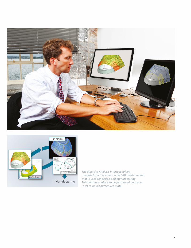
To ensure products meet specification and cost targets, you must address pro-duction challenges prior to release to manufacturing. Waiting to resolve these challenges until manufacturing can elimi-nate the advantages of using composites by increasing production time, labor costs and material scrap. Fibersim addresses these challenges and main-tains a collaborative product develop-ment process by updating the design with manufacturing design details.
Resolving material deformation, devia-tion and fiber buckling before layup reduces touch time and increases manu-facturing throughput. Fibersim addresses these challenges with flexible, auto-mated splicing and darting capabilities. Incorporating specifications including staggered splicing, splice overlap, no-splice region and no-dart region helps automate creation and ensures require-ments are met.
You must address automated deposition machine characteristics, such as mini-mum cut length and roller height travel, in the design to ensure optimal machine rate and throughput. Minimum cut length limitations require material addi-tions to the ply boundary, often manually added in path planning software or by hand during manufacturing. Roller height travel limits can cause material smear at the “cliff” edge of parts, often addressed by stopping the machine and manually shimming the part edge. Fibersim auto-matically identifies design for automated manufacturing requirements and applies ply boundary adjustments to maintain an accurate engineering and manufacturing definition.
Manufacturing design detail
Key functionality
Intelligently automated genera-tion of composite design for manufacturing features, including:
• Splicing• Darting• Flat pattern generation• Course generation• Minimum course vertex• Extended ramps
Benefits
• Increases production throughput by ensuring that all production challenges are addressed before manufacturing
• Reduces labor costs by cutting material touch time required for layup
• Reduces unnecessary material scrap by taking into consideration machine limitations during design
Enabling composite design for manufacturing that increases production
Fibersim provides several automated methods for addressing manufacturing challenges including splicing and darting. Darts, displayed as the two blue curves in the bend, are created while view-ing the material deformation. Smart capabilities automate the staggering of darts.
The Fibersim minimum course utility automatically identifies the corners where material additions (“bird beaks”) are required to en-sure minimum courses can be laid up during automated fiber placement and adds them to the ply boundaries.

17
The highest quality, lowest cost product requires repeatability of the manufactur-ing process. You can achieve this by using accurate information, eliminating ambiguity and increasing the use of pro-cess automation.
Repeatability of the hand layup manu-facturing process can be ensured by eliminating the manual creation and digi-tization of ply templates, incorporating laser assisted layup and creating process documentation that removes ambiguity. Automated tape laying and fiber place-ment ensure repeatability and eliminate ambiguity, but the composite definition is often manually created for path plan-ning and post generation.
Fibersim helps you quickly and accurately create documentation and data directly from the composite manufacturing rep-resentation, ensuring that the documen-tation and automated production system data are always current and accurate.
Manufacturing documentation and automation
Key functionality
• Layup plybook• Flat pattern export• Laser projection export/import• Automated tape laying export• Automated fiber placement
export/import• Publish Fibersim Composite
Format
Benefits
• Eliminates the need to manually create manu-facturing documentation for hand layup processes
• Increases production throughput and quality by removing the ambiguity in hand layup manufacturing processes
• Seamlessly transfers design data to automated production systems
Delivering accurate design data to the manufacturing floor
Fibersim generates plybook documentation needed for hand layup, which ensuresrepeatability and part quality by displaying the layup process.
Fibersim manufacturing interfaces support myriad manufacturing processes, including automated cutting, automated fiber placement, automated tape laying and laser projection.

18
Inspection is a critical part of the com-posite product certification process. First article inspection plans and automated inspection ensure accurate plans and execution. Fibersim can be used with Quality Planning Environment™ (QPE) software from Siemens PLM Software to generate quality plans and drive auto-mated ply verification systems for inspection.
You can import Fibersim composites data into QPE and arrange it in a standard inspection format. QPE then completes additional portions of the quality plans, such as dimensions, notes and balloons on items to be inspected. QPE stores the inspection plan in an associated quality model, which you can export in a stan-dard inspection plan format as needed. Alternatively, you can import an XML export into computer-aided process planning (CAPP) systems.
Producing the highest quality composite products requires that material, orienta-tion, location and order are correct dur-ing the manufacturing process. The required inspection is a time-consuming and costly manual process. Fibersim sup-ports efficient automated ply verification (APV) systems by directly using design data during inspection. You can import the Fibersim composite definition into an APV system, which uses a high-accuracy, manually positioned inspector to verify ply edges, location, material type, fiber orientation within specified tolerance, and ply sequence.
Product inspection
Key functionality
Automatically generates composite engineering data for plans that support the first article inspection (FAI) process, including:
• Plies• Cores
Benefits
• Reduces time to generate quality inspection plans for composite products by as much as 90 percent
• Delivers more thorough and accurate quality reports resulting in less documentation rework
Verifying that composite parts meet specifications
QPE automatically creates inspection characteristics – such as material type and ply orientation – for a shear tie of a composite fuselage based on ply information created in Fibersim or data extracted from specification tree formats or databases.
Dimensions, tolerances and notes defining design char-acteristics of the laminate are consumed into the QPE to provide a complete set of pre- and post-cure inspection requirements.

19
Fibersim compresses the design-to-manufacturing process for composite components up to 45 percent.
Successful composite product development requires effective communication among multi-discipline teams throughout the lifecycle of a product. Fibersim transforms – and ultimately reduces – the entire composite product development process by providing an open architecture that allows concurrent engi-neering and easy exchange of information between analysts, designers and manufacturing engineers. It automates the tedious design and iterative tasks associated with making changes – all while ensuring awareness of the impact of those changes – so composite products can be developed faster and without errors. Fibersim also improves product quality and throughput time by delivering automated manufacturing and inspection data directly from the design to the factory floor, ensuring a repeatable manufacturing process. The combina-tion of these unique features makes Fibersim the best tool available to deliver innovative, optimized composite products that meet all specifications, on time and within budget.
Integrate the entire composite product development process
“The quality of manufacturing data provided by Fibersim is better than anything our supplier has ever had.”Ian Goddard, Senior CAE Engineer Lotus F1 Team
Fibersim delivers:
Provides a collaborative composite product develop-ment process through an open architecture
Achieves as much as 80 percent time savings to create composite designs
Reduces time to make design changes by as much as 95 percent
Ensures adherence to composite engineering specifica-tions and standards
Increases confidence in product performance by elimi-nating ambiguity in desired fiber orientations and pro-viding feedback on true fiber orientations
Preliminarydesign
Detaileddesign
Designverification
Design formanufacturing
Manufacturingplanning andautomation
Inspection
Design
Design
Manufacturing
Manufacturing

About Siemens PLM Software
Siemens PLM Software, a business unit of the Siemens Industry Automation Division, is a leading global provider of product lifecycle management (PLM) software and services with 7 million licensed seats and 71,000 customers worldwide. Headquartered in Plano, Texas, Siemens PLM Software works collaboratively with companies to deliver open solutions that help them turn more ideas into successful products. For more information on Siemens PLM Software products and services, visit www.siemens.com/plm.
© 2012 Vistagy, Inc. All rights reserved. Siemens and the Siemens logo are registered trademarks of Siemens AG. Fibersim and Quality Planning Environment are trademarks of Siemens Product Lifecycle Management Software Inc. and/or its subsidiaries in the United States and in other countries. All other trademarks, registered trademarks or service marks belong to their respective holders.
29555-X15 3/12 A
Siemens Industry Software
+1 781 250 6800