Embed Size (px)
Citation preview
www.siemens.com/plm
White PaperIntegrated explode, render and animation capabilities, combined with motion simulation, allow you to create dynamic photorealistic animations and motion studies using existing Solid Edge® software 3D models to share and articulate design ideas, reduce risk and generate new business.
Siemens PLM Software
Solid Edge motion simulation, explode – render – animate
1A white paper issued by: Siemens PLM Software.
White paper | Solid Edge motion simulation, explode – render – animate
A white paper issued by: Siemens PLM Software. 2
Contents
Introduction .....................................................................3
Full motion simulation .....................................................4
Explode – render – animate .............................................5Explode – clear visualization ..............................................5Animation – bringing your designs to life ...........................6Advanced rendering with KeyShot ......................................6
Commands, features and workflows ................................8Smartstep .........................................................................8Motion studies ..................................................................8Explode ...........................................................................10Animation .......................................................................10
Conclusion .....................................................................11
White paper | Solid Edge motion simulation, explode – render – animate
A white paper issued by: Siemens PLM Software. 3
IntroductionMany companies already recognize the benefits of using 3D for design work. Solid Edge goes beyond building assemblies and allows companies to extend their CAD data to be used by design review teams, communicate and market their prod-ucts, help manufacturing and instruct shop floor assembly workers and field engineers. Solid Edge explode-render- animate capabilities (ERA) enables:
• Design review teams to collaborate and share their products and ideas
• Project engineers/leaders to visualize, communicate and market products internally or with customers and use engineering data to visualize designs and fix errors before building expensive physical prototypes
• Manufacturing engineers and process planners define tooling and production process, communicate design intent and manufacturing sequences (assembly/ disassembly) to shop floor
• Service teams can create interactive animations of products using Solid Edge assemblies to train shop floor assembly personnel, co-workers and field engineers, as well as using engineering data to quickly produce technical publications for service and repair manuals
Design collaboration across all points of the value chain
Globally distributed partner networks are no longer the sole domain of large OEMs. It is now common for small and mid-size companies to participate in or even drive multiple, highly competitive supply chains, each placing rigorous demands on product development speed, quality and costs.
Collaboration is critical to successful product design, and with Solid Edge, OEMs and suppliers can improve and manage collaboration across design teams, regardless of location. By reducing design revisions and communication delays, our customers enjoy quicker time-to-market and increased profitability.
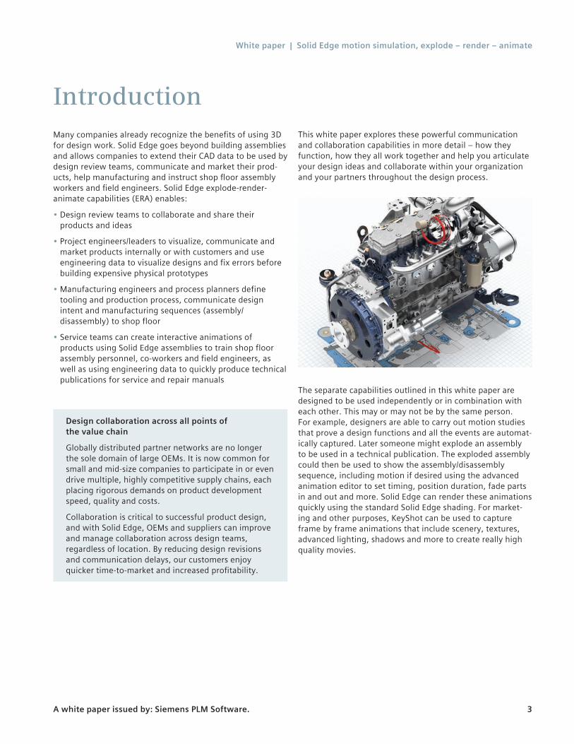
This white paper explores these powerful communication and collaboration capabilities in more detail – how they function, how they all work together and help you articulate your design ideas and collaborate within your organization and your partners throughout the design process.
The separate capabilities outlined in this white paper are designed to be used independently or in combination with each other. This may or may not be by the same person. For example, designers are able to carry out motion studies that prove a design functions and all the events are automat-ically captured. Later someone might explode an assembly to be used in a technical publication. The exploded assembly could then be used to show the assembly/disassembly sequence, including motion if desired using the advanced animation editor to set timing, position duration, fade parts in and out and more. Solid Edge can render these animations quickly using the standard Solid Edge shading. For market-ing and other purposes, KeyShot can be used to capture frame by frame animations that include scenery, textures, advanced lighting, shadows and more to create really high quality movies.
White paper | Solid Edge motion simulation, explode – render – animate
A white paper issued by: Siemens PLM Software. 4
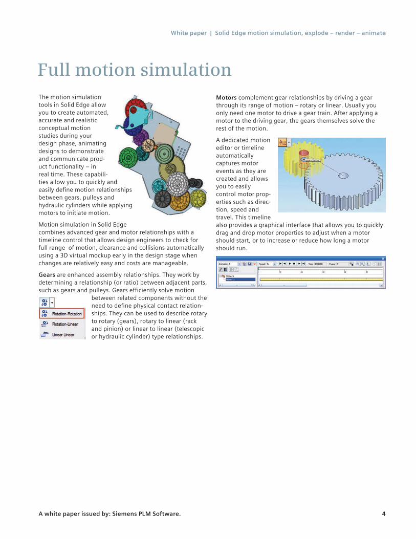
Full motion simulationThe motion simulation tools in Solid Edge allow you to create automated, accurate and realistic conceptual motion studies during your design phase, animating designs to demonstrate and communicate prod-uct functionality – in real time. These capabili-ties allow you to quickly and easily define motion relationships between gears, pulleys and hydraulic cylinders while applying motors to initiate motion.
Motion simulation in Solid Edge combines advanced gear and motor relationships with a timeline control that allows design engineers to check for full range of motion, clearance and collisions automatically using a 3D virtual mockup early in the design stage when changes are relatively easy and costs are manageable.
Gears are enhanced assembly relationships. They work by determining a relationship (or ratio) between adjacent parts, such as gears and pulleys. Gears efficiently solve motion
between related components without the need to define physical contact relation-ships. They can be used to describe rotary to rotary (gears), rotary to linear (rack and pinion) or linear to linear (telescopic or hydraulic cylinder) type relationships.
Motors complement gear relationships by driving a gear through its range of motion – rotary or linear. Usually you only need one motor to drive a gear train. After applying a motor to the driving gear, the gears themselves solve the rest of the motion.
A dedicated motion editor or timeline automatically captures motor events as they are created and allows you to easily control motor prop-erties such as direc-tion, speed and travel. This timeline also provides a graphical interface that allows you to quickly drag and drop motor properties to adjust when a motor should start, or to increase or reduce how long a motor should run.
White paper | Solid Edge motion simulation, explode – render – animate
A white paper issued by: Siemens PLM Software. 5
Explode – render – animateIt is one thing for engineers to be able to create motion stud-ies and check for design errors using Solid Edge. But to truly communicate and share your designs outside of the engi-neering department and bring your designs to life, you need a little more from your 3D design system.
Explode – render – animate (ERA) capabilities included in Solid Edge allow mechanisms to be in motion while exploded views depict your design being assembled or disassembled. At the same time you are able to control camera angle and position, zoom in for close up views of important details and apply photo realistic rendering settings to create exceptional animations that help sell your products and communicate your designs.
Explode – render – animate can be used to produce dynamic documentation that helps communicate ideas and designs to nonengineers, create technical illustrations in maintenance and repair manuals for field engineers and communicate clearer assembly manufacturing instructions and training videos for the shop floor, using dynamic 3D motion, AVI movies and technical illustrations.
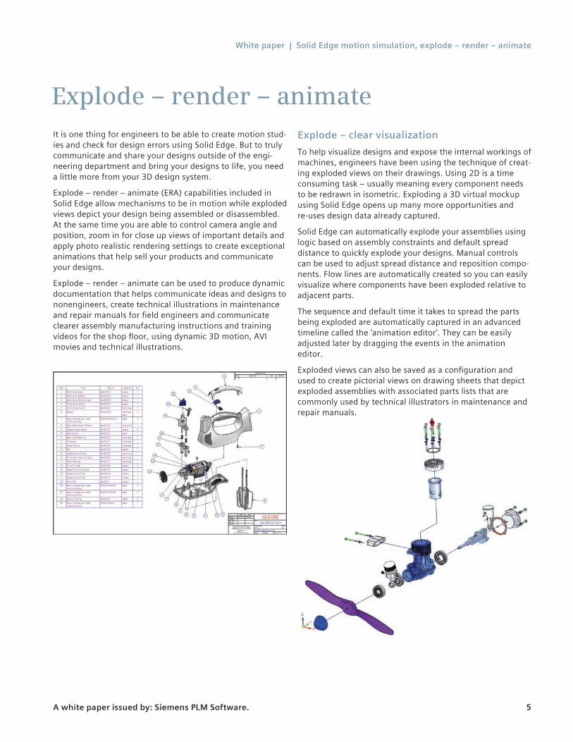
Explode – clear visualization To help visualize designs and expose the internal workings of machines, engineers have been using the technique of creat-ing exploded views on their drawings. Using 2D is a time consuming task – usually meaning every component needs to be redrawn in isometric. Exploding a 3D virtual mockup using Solid Edge opens up many more opportunities and re-uses design data already captured.
Solid Edge can automatically explode your assemblies using logic based on assembly constraints and default spread distance to quickly explode your designs. Manual controls can be used to adjust spread distance and reposition compo-nents. Flow lines are automatically created so you can easily visualize where components have been exploded relative to adjacent parts.
The sequence and default time it takes to spread the parts being exploded are automatically captured in an advanced timeline called the ‘animation editor’. They can be easily adjusted later by dragging the events in the animation editor.
Exploded views can also be saved as a configuration and used to create pictorial views on drawing sheets that depict exploded assemblies with associated parts lists that are commonly used by technical illustrators in maintenance and repair manuals.
White paper | Solid Edge motion simulation, explode – render – animate
A white paper issued by: Siemens PLM Software. 6
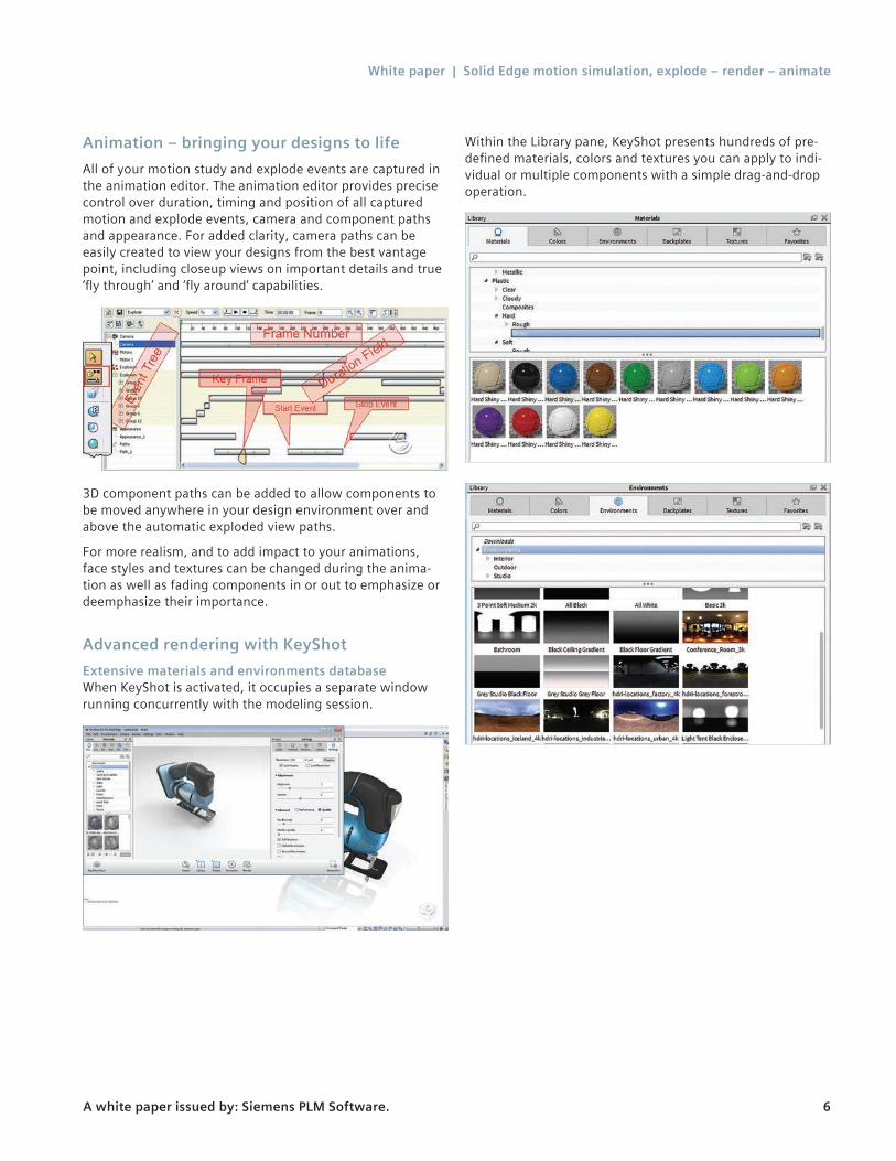
Animation – bringing your designs to life All of your motion study and explode events are captured in the animation editor. The animation editor provides precise control over duration, timing and position of all captured motion and explode events, camera and component paths and appearance. For added clarity, camera paths can be easily created to view your designs from the best vantage point, including closeup views on important details and true ‘fly through’ and ‘fly around’ capabilities.
3D component paths can be added to allow components to be moved anywhere in your design environment over and above the automatic exploded view paths.
For more realism, and to add impact to your animations, face styles and textures can be changed during the anima-tion as well as fading components in or out to emphasize or deemphasize their importance.
Advanced rendering with KeyShotExtensive materials and environments database When KeyShot is activated, it occupies a separate window running concurrently with the modeling session.
Within the Library pane, KeyShot presents hundreds of pre-defined materials, colors and textures you can apply to indi-vidual or multiple components with a simple drag-and-drop operation.
White paper | Solid Edge motion simulation, explode – render – animate
A white paper issued by: Siemens PLM Software. 7
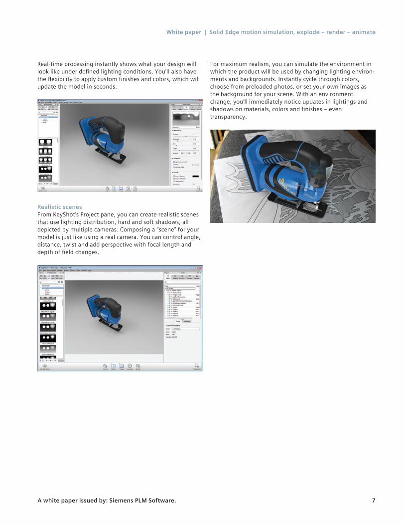
Real-time processing instantly shows what your design will look like under defined lighting conditions. You’ll also have the flexibility to apply custom finishes and colors, which will update the model in seconds.
Realistic scenesFrom KeyShot’s Project pane, you can create realistic scenes that use lighting distribution, hard and soft shadows, all depicted by multiple cameras. Composing a “scene” for your model is just like using a real camera. You can control angle, distance, twist and add perspective with focal length and depth of field changes.
For maximum realism, you can simulate the environment in which the product will be used by changing lighting environ-ments and backgrounds. Instantly cycle through colors, choose from preloaded photos, or set your own images as the background for your scene. With an environment change, you’ll immediately notice updates in lightings and shadows on materials, colors and finishes – even transparency.
White paper | Solid Edge motion simulation, explode – render – animate
A white paper issued by: Siemens PLM Software. 8
Commands, features and workflows
The remainder of this document explores some of the specific commands, features and workflows that make Solid Edge dynamic documentation capabilities such a powerful collaboration tool.
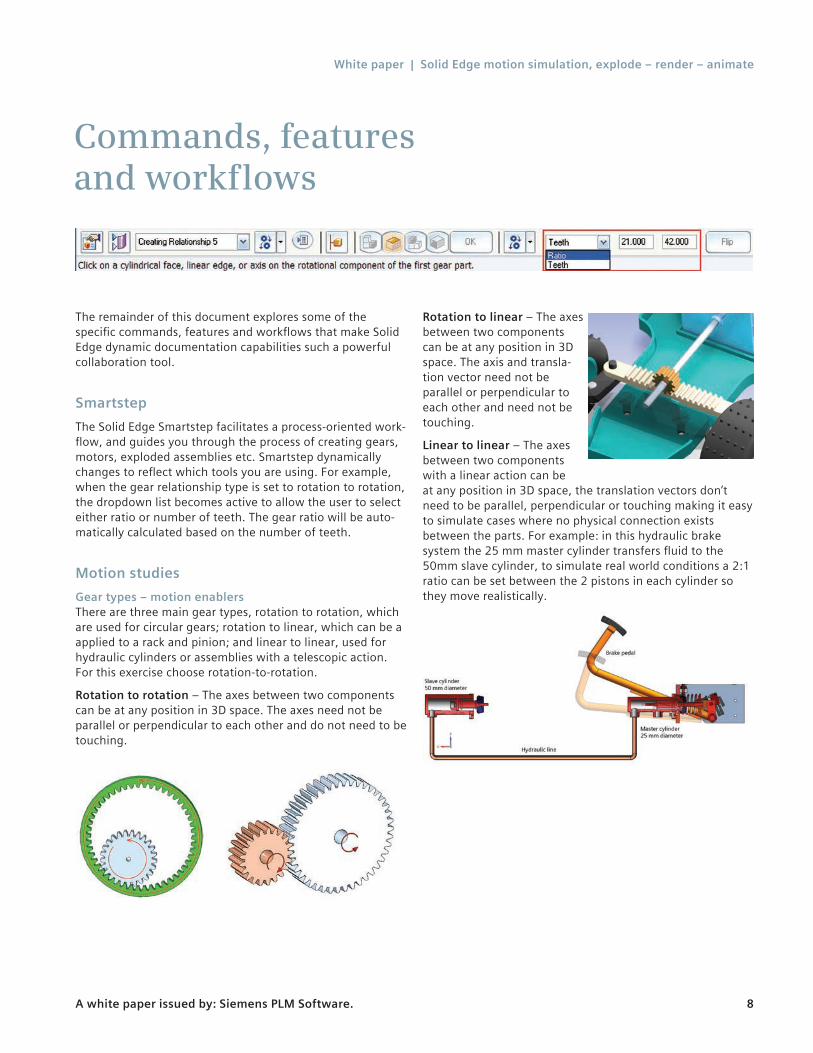
SmartstepThe Solid Edge Smartstep facilitates a process-oriented work-flow, and guides you through the process of creating gears, motors, exploded assemblies etc. Smartstep dynamically changes to reflect which tools you are using. For example, when the gear relationship type is set to rotation to rotation, the dropdown list becomes active to allow the user to select either ratio or number of teeth. The gear ratio will be auto-matically calculated based on the number of teeth.
Motion studiesGear types – motion enablersThere are three main gear types, rotation to rotation, which are used for circular gears; rotation to linear, which can be a applied to a rack and pinion; and linear to linear, used for hydraulic cylinders or assemblies with a telescopic action. For this exercise choose rotation-to-rotation.
Rotation to rotation – The axes between two components can be at any position in 3D space. The axes need not be parallel or perpendicular to each other and do not need to be touching.
Rotation to linear – The axes between two components can be at any position in 3D space. The axis and transla-tion vector need not be parallel or perpendicular to each other and need not be touching.
Linear to linear – The axes between two components with a linear action can be at any position in 3D space, the translation vectors don’t need to be parallel, perpendicular or touching making it easy to simulate cases where no physical connection exists between the parts. For example: in this hydraulic brake system the 25 mm master cylinder transfers fluid to the 50mm slave cylinder, to simulate real world conditions a 2:1 ratio can be set between the 2 pistons in each cylinder so they move realistically.
White paper | Solid Edge motion simulation, explode – render – animate
A white paper issued by: Siemens PLM Software. 9
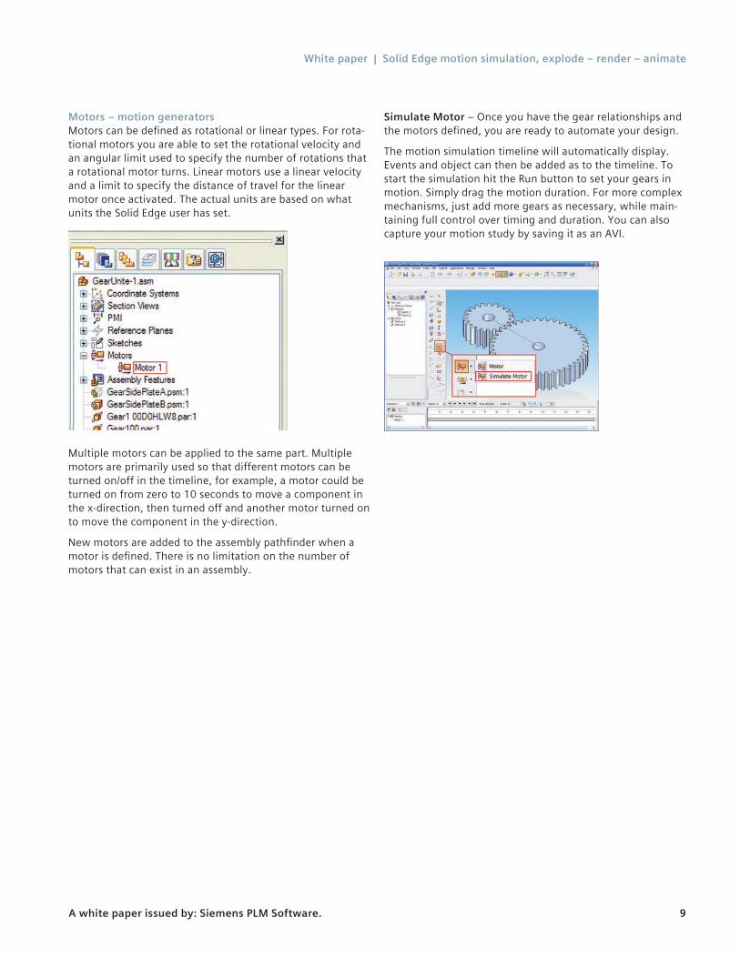
Motors – motion generatorsMotors can be defined as rotational or linear types. For rota-tional motors you are able to set the rotational velocity and an angular limit used to specify the number of rotations that a rotational motor turns. Linear motors use a linear velocity and a limit to specify the distance of travel for the linear motor once activated. The actual units are based on what units the Solid Edge user has set.
Multiple motors can be applied to the same part. Multiple motors are primarily used so that different motors can be turned on/off in the timeline, for example, a motor could be turned on from zero to 10 seconds to move a component in the x-direction, then turned off and another motor turned on to move the component in the y-direction.
New motors are added to the assembly pathfinder when a motor is defined. There is no limitation on the number of motors that can exist in an assembly.
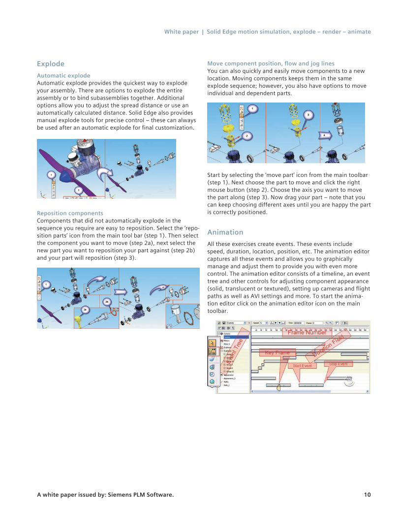
Simulate Motor – Once you have the gear relationships and the motors defined, you are ready to automate your design.
The motion simulation timeline will automatically display. Events and object can then be added as to the timeline. To start the simulation hit the Run button to set your gears in motion. Simply drag the motion duration. For more complex mechanisms, just add more gears as necessary, while main-taining full control over timing and duration. You can also capture your motion study by saving it as an AVI.
White paper | Solid Edge motion simulation, explode – render – animate
A white paper issued by: Siemens PLM Software. 10
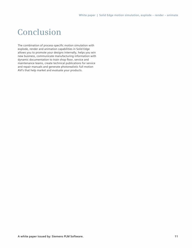
ExplodeAutomatic explodeAutomatic explode provides the quickest way to explode your assembly. There are options to explode the entire assembly or to bind subassemblies together. Additional options allow you to adjust the spread distance or use an automatically calculated distance. Solid Edge also provides manual explode tools for precise control – these can always be used after an automatic explode for final customization.
Reposition componentsComponents that did not automatically explode in the sequence you require are easy to reposition. Select the ‘repo-sition parts’ icon from the main tool bar (step 1). Then select the component you want to move (step 2a), next select the new part you want to reposition your part against (step 2b) and your part will reposition (step 3).
Move component position, flow and jog linesYou can also quickly and easily move components to a new location. Moving components keeps them in the same explode sequence; however, you also have options to move individual and dependent parts.
Start by selecting the ‘move part’ icon from the main toolbar (step 1). Next choose the part to move and click the right mouse button (step 2). Choose the axis you want to move the part along (step 3). Now drag your part – note that you can keep choosing different axes until you are happy the part is correctly positioned.
AnimationAll these exercises create events. These events include speed, duration, location, position, etc. The animation editor captures all these events and allows you to graphically manage and adjust them to provide you with even more control. The animation editor consists of a timeline, an event tree and other controls for adjusting component appearance (solid, translucent or textured), setting up cameras and flight paths as well as AVI settings and more. To start the anima-tion editor click on the animation editor icon on the main toolbar.
White paper | Solid Edge motion simulation, explode – render – animate
A white paper issued by: Siemens PLM Software. 11
The combination of process-specific motion simulation with explode, render and animation capabilities in Solid Edge allows you to promote your designs internally, helps you win new business, communicate manufacturing information with dynamic documentation to train shop floor, service and maintenance teams, create technical publications for service and repair manuals and generate photorealistic full motion AVI’s that help market and evaluate your products.
Conclusion
White paper | Solid Edge motion simulation, explode – render – animate
A white paper issued by: Siemens PLM Software. 12
www.siemens.com/plm © 2014 Siemens Product Lifecycle Management Software Inc. Siemens and the Siemens logo are registered trademarks of Siemens AG. D-Cubed, Femap, Fibersim, Geolus, GO PLM, I-deas, JT, NX, Parasolid, Solid Edge, Syncrofit, Teamcenter and Tecnomatix are trademarks or registered trademarks of Siemens Product Lifecycle Management Software Inc. or its subsidiaries in the United States and in other countries. Nastran is a registered trademark of the National Aeronautics and Space Administration. All other logos, trademarks, registered trademarks or service marks belong to their respective holders. 10171-Y5 10/14 C
Siemens PLM Software Headquarters Granite Park One 5800 Granite Parkway Suite 600 Plano, TX 75024 USA +1 972 987 3000 Americas Granite Park One 5800 Granite Parkway Suite 600 Plano, TX 75024 USA +1 314 264 8287 Europe Stephenson House Sir William Siemens Square Frimley, Camberley Surrey, GU16 8QD +44 (0) 1276 413200 Asia-Pacific Suites 4301-4302, 43/F AIA Kowloon Tower, Landmark East 100 How Ming Street Kwun Tong, Kowloon Hong Kong +852 2230 3308
About Siemens PLM SoftwareSiemens PLM Software, a business unit of the SiemensDigital Factory Division, is a world-leading provider of product lifecycle management (PLM) software, systems and services with nine million licensed seats and 77,000 customers worldwide. Headquartered in Plano, Texas, Siemens PLM Software helps thousands of companies make great products by optimizing their lifecycle processes, from planning and development through manufacturing and support. Our HD-PLM vision is to give everyone involved in making a product the information they need, when they need it, to make the smartest decisions. For more informa-tion on Siemens PLM Software products and services, visit www.siemens.com/plm.