Embed Size (px)
Citation preview

Sign Command User Manual
©J.M. Stewart Corporation Page 1 Document revision 12/6/2012
User Manual for Sign Command Version 1.10 and Higher
This user manual describes the operating functions and features of the Sign Command software v1.10
and higher for your Stewart TekStar LED display. For additional support, please contact:
2201 Cantu Ct. Suite 215
Sarasota, FL 34232
1-800-237-3928
- or visit our TekStar Support website at -
www.stewartsigns.com/support/tekstar
Sign Command User Manual
©J.M. Stewart Corporation Page 2 Document revision 12/6/2012
Copyright Notice, Terms and Conditions ©J.M. Stewart Corporation
This software is subject to the following license terms and conditions. Please read this license before installing the software on
your PC. If you do not agree to the terms and conditions of this license you may return the software for a full refund.
BY CLICKING ON THE "ACCEPT" BUTTON, OPENING THE PACKAGE, DOWNLOADING THE PRODUCT OR USING THE EQUIPMENT
THAT CONTAINS THIS PRODUCT, YOU ARE CONSENTING TO BE BOUND BY THIS AGREEMENT. IF YOU DO NOT AGREE TO ALL OF
THE TERMS OF THIS AGREEMENT, CLICK THE "DO NOT ACCEPT" BUTTON AND THE INSTALLATION PROCESS WILL NOT
CONTINUE, RETURN THE PRODUCT TO THE PLACE OF PURCHASE FOR A FULL REFUND, OR DO NOT DOWNLOAD THE PRODUCT.
SINGLE COPY SOFTWARE LICENSE
THIS IS A SINGLE COPY SOFTWARE LICENSE granted by the J.M. Stewart Corporation (“Stewart Signs”), with its mailing address
at 2201 Cantu Ct., Suite 215, Sarasota, FL 34232. The software in this package is licensed to you as the end user. It is not for
resale.
1.0 License
1.1 The software enclosed in this package is copyrighted material. Once you have paid the required single copy
license fee, you may use the software for as long as you like provided you do not violate the copyright and if
you follow these simple rules.
1.1.1 You may use the software on multiple computers for which it is designed.
1.1.2 You may not make any changes or modifications to the licensed software, and you may not
decompile, disassemble, or otherwise reverse engineer the software.
1.1.3 You may not rent it or lease it to others.
2.0 Limited Warranty
2.1 Stewart Signs warrants that the media which the software is recorded on and the documentation provided
with it are free from defects in materials and workmanship under normal use.
2.2 Stewart Signs warrants that the software itself will perform substantially in accordance with the specifications
set forth in the documentation provided with it.
2.3 The above express warranties are made for a period of ninety (90) days from the date the software is
delivered to you as the first user.
2.4 Obligations of Stewart Signs during the warranty period:
2.4.1 Stewart Signs will replace the CD which proves defective in materials or workmanship, without
additional charge, on an exchange basis. In the case of an error in the documentation, Stewart
Signs will correct errors in the documentation without charge by providing addenda or substitute
pages.
2.4.2 Stewart Signs will either replace or repair without additional charge any software that does not
perform in substantial accordance with the specifications of the documentation. This will be done
by delivering to you a corrected copy of the software or corrective code, on an exchange basis.
2.4.3 If Stewart Signs is unable to replace defective documentation or defective media or if Stewart
Signs is unable to provide a corrected copy of the software or corrected documentation within a
reasonable period of time, Stewart Signs will either replace the software with a functionally
similar program or refund the license fees paid for use of the software.
2.5 Exclusion of other Warranties
2.5.1 Stewart Signs does not warrant that the functions contained in the software will meet your
requirements or that the operation of the software will be uninterrupted or error free.
2.5.2 The warranty does not cover any media or documentation which has been subjected to damage
or abuse by you.
2.5.3 The software warranty does not cover any copy of the software which has been altered or
changed in any way by you or others.
2.5.4 Stewart Signs is not responsible for problems caused by changes in the operating characteristics
of the computer hardware or operating system which are made after the delivery of the software.
Sign Command User Manual
©J.M. Stewart Corporation Page 3 Document revision 12/6/2012
2.6 Any implied warranties including any warranties of merchantability or fitness for a particular purpose are
limited to the term of the express warranties.
2.6.1 Some states do not allow limitations on how long an implied warranty lasts, so the above
limitation may not apply to you.
2.7 Stewart Signs shall not in any case be liable for special, incidental, consequential, indirect or other similar
damages arising from any breach of these warranties even if Stewart Signs or its agent has been advised of
the possibility of such damages.
2.7.1 Some States do not allow the exclusion or limitation of incidental or consequential damages, so
the above limitation or exclusion may not apply to you.
DISCLAIMER: EXCEPT AS SPECIFIED IN THIS WARRANTY, ALL EXPRESS OR IMPLIED CONDITIONS,
REPRESENTATIONS, AND WARRANTIES INCLUDING, WITHOUT LIMITATION, ANY IMPLIED WARRANTY OF
MERCHANTABILITY, FITNESS FOR A PARTICULAR PURPOSE, NONINFRINGEMENT OR ARISING FROM A COURSE OF
DEALING, USAGE, OR TRADE PRACTICE, ARE HEREBY EXCLUDED TO THE EXTENT ALLOWED BY APPLICABLE LAW.
IN NO EVENT WILL STEWART SIGNS OR ITS SUBSIDIARIES, DIVISIONS OR SUPPLIERS BE LIABLE FOR ANY LOST
REVENUE, PROFIT, OR DATA, OR FOR SPECIAL, INDIRECT, CONSEQUENTIAL, INCIDENTAL, OR PUNITIVE DAMAGES
HOWEVER CAUSED AND REGARDLESS OF THE THEORY OF LIABILITY ARISING OUT OF THE USE OF OR INABILITY
TO USE THE SOFTWARE EVEN IF STEWART SIGNS OR ITS SUPPLIERS HAVE BEEN ADVISED OF THE POSSIBILITY OF
SUCH DAMAGES. In no event shall Stewart Signs’ or its suppliers’ liability to Customer, whether in contract, tort
(including negligence), or otherwise, exceed the price paid by Customer. The foregoing limitations shall apply
even if the above-stated warranty fails of its essential purpose.
2.8 Your Obligations Under The Warranty:
2.8.1 You must call Stewart Signs customer service department for authorization to return any defective
item to Stewart Signs, during the warranty period.
2.8.2 If Stewart Signs customer service representative is unable to correct your problem by telephone,
you will be provided with a return authorization number and an address for returning the
defective item for warranty service or replacement.
2.8.3 You must insure any defective item being returned because Stewart Signs does not assume the
risk of loss or damage while in transit.
2.9 Other Conditions:
2.9.1 The warranties set forth above are in lieu of all other express and implied warranties, whether
oral, written or implied, and the remedies set forth above are your sole and exclusive remedies.
2.9.2 Only an authorized officer of Stewart Signs may make modifications to this warranty, or additional
warranties binding on Stewart Signs.
2.9.3 Accordingly, additional statements such as advertising or presentations whether written, oral or
implied do not constitute warranties by Stewart Signs and should not be relied upon as such.
2.9.4 This warranty gives you specific legal rights, and you may also have other rights which may vary
from state to state.
3.0 Limitation Of Liability
3.1 In no case shall Stewart Signs’ liability exceed the license fees paid for the right to use the Licensed Software
or One Hundred Dollars ($100.00), whichever is greater.
4.0 Integration
4.1 This License shall be governed by and construed in accordance with the laws of the State of Florida, United
States of America, as if performed wholly within the state and without giving effect to the principles of
conflict of law. If any portion hereof is found to be void or unenforceable, the remaining provisions of this
License shall remain in full force and effect. This license constitutes the entire agreement and understanding
between the parties and supersedes any prior agreement or understanding whether written, oral or implied,
relating to the subject of this license.
4.2 This agreement may only be modified by a written agreement signed by Stewart Signs.
Sign Command User Manual
©J.M. Stewart Corporation Page 4 Document revision 12/6/2012
Table of Contents
What is Sign Command? ................................................................................................................... 5
Terminology ...................................................................................................................................... 5
System Requirements ....................................................................................................................... 5
Installing the Software ...................................................................................................................... 6
Activating the Software .................................................................................................................... 7
Configuring the Display .................................................................................................................... 8
Screen Overview .............................................................................................................................. 9
Working with Script Files .................................................................................................................. 10
Understanding Frames, Windows & Display Items ........................................................................... 10
Working with Frames ........................................................................................................................ 11
Working with Display Items .............................................................................................................. 11
Adding Pixel Text .................................................................................................................. 12
Adding Text .......................................................................................................................... 12
Adding Images ...................................................................................................................... 13
Adding Video Clips ............................................................................................................... 14
Adding the Date & Time ....................................................................................................... 14
Adding the Temperature ...................................................................................................... 15
Scheduling a Frame ........................................................................................................................... 16
Previewing a Frame ........................................................................................................................... 17
Transmitting to the Display ............................................................................................................... 18
Exporting to USB ............................................................................................................................... 18
Working with Multiple Windows ...................................................................................................... 19
Setting Password Protection ............................................................................................................. 19
Changing the Time ............................................................................................................................ 20
Power and Brightness Control .......................................................................................................... 21
Setting Other Options ....................................................................................................................... 22
Appendix
Connecting with a Laptop ................................................................................................... 23
Changing the Sign’s IP Address ............................................................................................ 26
Upgrading the Firmware ...................................................................................................... 27
Installing Wireless Hardware ............................................................................................... 28
Troubleshooting a Network Connection ............................................................................. 30
Troubleshooting a USB Drive .............................................................................................. 31
The Information boxes located within
this manual contain additional
important notes.
Alert boxes contain instructions that
must be followed to ensure proper
performance of the software or display.
Sign Command User Manual
©J.M. Stewart Corporation Page 5 Document revision 12/6/2012
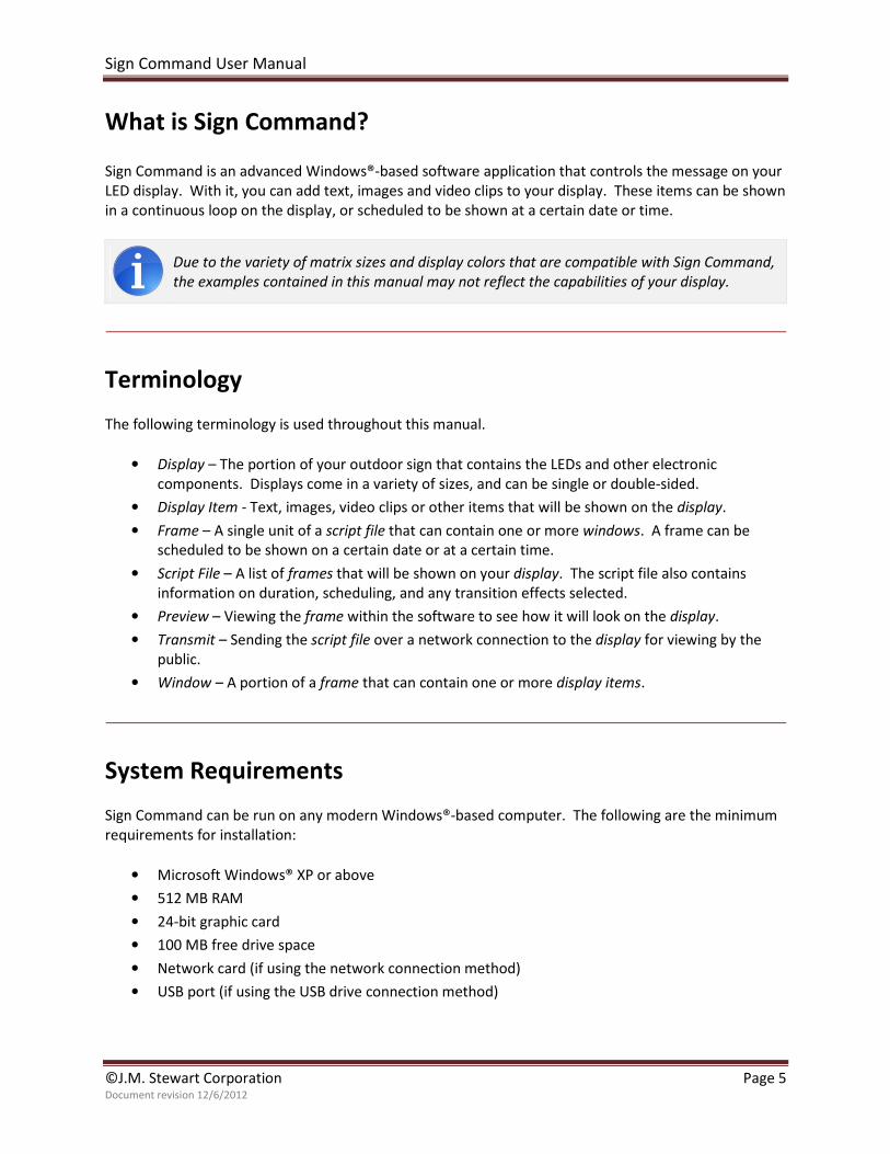
What is Sign Command?
Sign Command is an advanced Windows®-based software application that controls the message on your
LED display. With it, you can add text, images and video clips to your display. These items can be shown
in a continuous loop on the display, or scheduled to be shown at a certain date or time.
Due to the variety of matrix sizes and display colors that are compatible with Sign Command,
the examples contained in this manual may not reflect the capabilities of your display.
Terminology
The following terminology is used throughout this manual.
• Display – The portion of your outdoor sign that contains the LEDs and other electronic
components. Displays come in a variety of sizes, and can be single or double-sided.
• Display Item - Text, images, video clips or other items that will be shown on the display.
• Frame – A single unit of a script file that can contain one or more windows. A frame can be
scheduled to be shown on a certain date or at a certain time.
• Script File – A list of frames that will be shown on your display. The script file also contains
information on duration, scheduling, and any transition effects selected.
• Preview – Viewing the frame within the software to see how it will look on the display.
• Transmit – Sending the script file over a network connection to the display for viewing by the
public.
• Window – A portion of a frame that can contain one or more display items.
System Requirements
Sign Command can be run on any modern Windows®-based computer. The following are the minimum
requirements for installation:
• Microsoft Windows® XP or above
• 512 MB RAM
• 24-bit graphic card
• 100 MB free drive space
• Network card (if using the network connection method)
• USB port (if using the USB drive connection method)
Sign Command User Manual
©J.M. Stewart Corporation Page 6 Document revision 12/6/2012
Installing the Software
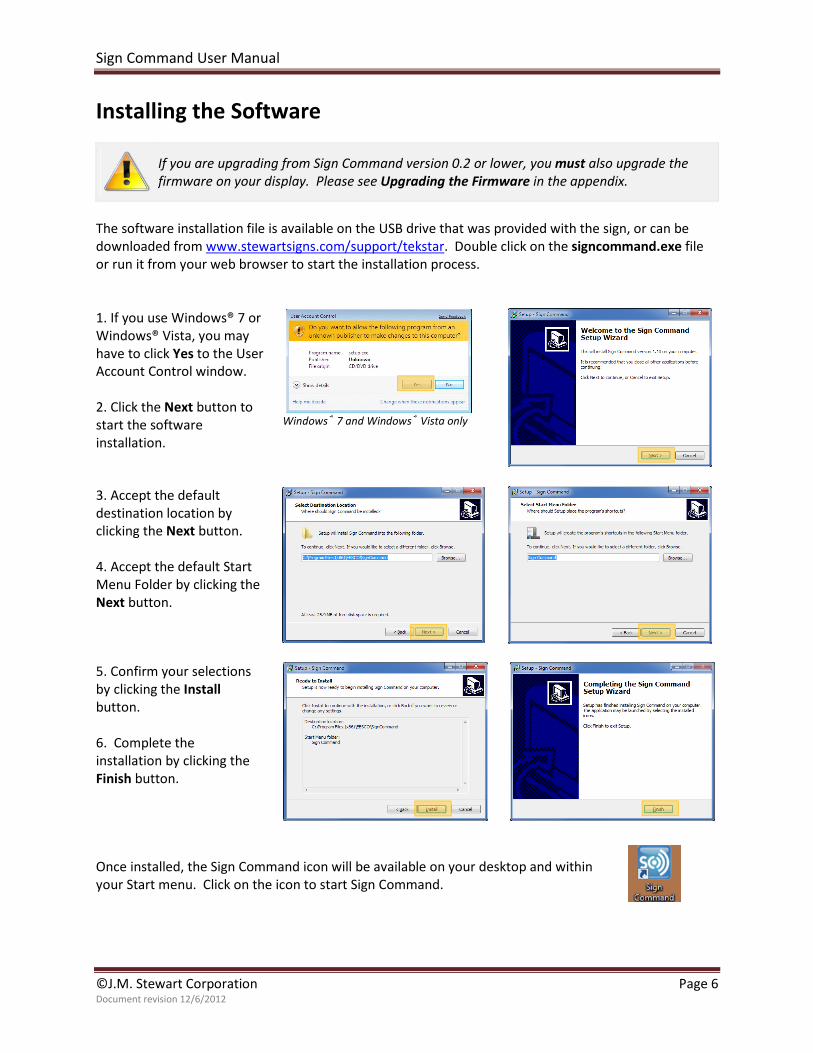
If you are upgrading from Sign Command version 0.2 or lower, you must also upgrade the
firmware on your display. Please see Upgrading the Firmware in the appendix.
The software installation file is available on the USB drive that was provided with the sign, or can be
downloaded from www.stewartsigns.com/support/tekstar. Double click on the signcommand.exe file
or run it from your web browser to start the installation process.
1. If you use Windows® 7 or
Windows® Vista, you may
have to click Yes to the User
Account Control window.
2. Click the Next button to
start the software
installation.
Windows® 7 and Windows® Vista only
3. Accept the default
destination location by
clicking the Next button.
4. Accept the default Start
Menu Folder by clicking the
Next button.
5. Confirm your selections
by clicking the Install
button.
6. Complete the
installation by clicking the
Finish button.
Once installed, the Sign Command icon will be available on your desktop and within
your Start menu. Click on the icon to start Sign Command.
Sign Command User Manual
©J.M. Stewart Corporation Page 7 Document revision 12/6/2012
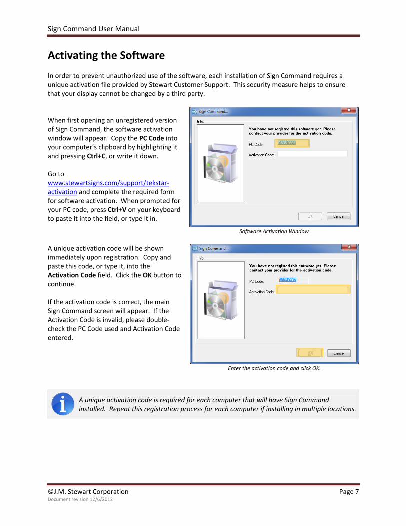
Activating the Software
In order to prevent unauthorized use of the software, each installation of Sign Command requires a
unique activation file provided by Stewart Customer Support. This security measure helps to ensure
that your display cannot be changed by a third party.
When first opening an unregistered version
of Sign Command, the software activation
window will appear. Copy the PC Code into
your computer’s clipboard by highlighting it
and pressing Ctrl+C, or write it down.
Go to
www.stewartsigns.com/support/tekstar-
activation and complete the required form
for software activation. When prompted for
your PC code, press Ctrl+V on your keyboard
to paste it into the field, or type it in.
Software Activation Window
A unique activation code will be shown
immediately upon registration. Copy and
paste this code, or type it, into the
Activation Code field. Click the OK button to
continue.
If the activation code is correct, the main
Sign Command screen will appear. If the
Activation Code is invalid, please double-
check the PC Code used and Activation Code
entered.
Enter the activation code and click OK.
A unique activation code is required for each computer that will have Sign Command
installed. Repeat this registration process for each computer if installing in multiple locations.
Sign Command User Manual
©J.M. Stewart Corporation Page 8 Document revision 12/6/2012
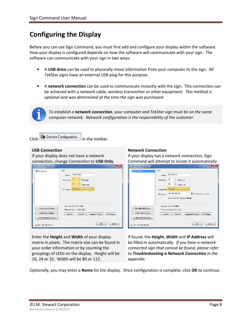
Configuring the Display
Before you can use Sign Command, you must first add and configure your display within the software.
How your display is configured depends on how the software will communicate with your sign. The
software can communicate with your sign in two ways:
• A USB drive can be used to physically move information from your computer to the sign. All
TekStar signs have an external USB plug for this purpose.
• A network connection can be used to communicate instantly with the sign. This connection can
be achieved with a network cable, wireless transmitter or other equipment. This method is
optional and was determined at the time the sign was purchased.
To establish a network connection, your computer and TekStar sign must be on the same
computer network. Network configuration is the responsibility of the customer.
Click in the toolbar.
USB Connection
If your display does not have a network
connection, change Connection to USB Only.
Enter the Height and Width of your display
matrix in pixels. The matrix size can be found in
your order information or by counting the
groupings of LEDs on the display. Height will be
16, 24 or 32. Width will be 80 or 112.
Network Connection
If your display has a network connection, Sign
Command will attempt to locate it automatically.
If found, the Height, Width and IP Address will
be filled in automatically. If you have a network
connected sign that cannot be found, please refer
to Troubleshooting a Network Connection in the
appendix.
Optionally, you may enter a Name for the display. Once configuration is complete, click OK to continue.
Sign Command User Manual
©J.M. Stewart Corporation Page 9 Document revision 12/6/2012
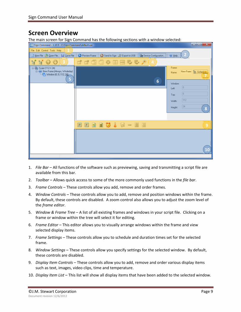
Screen Overview The main screen for Sign Command has the following sections with a window selected:
1. File Bar – All functions of the software such as previewing, saving and transmitting a script file are
available from this bar.
2. Toolbar – Allows quick access to some of the more commonly used functions in the file bar.
3. Frame Controls – These controls allow you add, remove and order frames.
4. Window Controls – These controls allow you to add, remove and position windows within the frame.
By default, these controls are disabled. A zoom control also allows you to adjust the zoom level of
the frame editor.
5. Window & Frame Tree – A list of all existing frames and windows in your script file. Clicking on a
frame or window within the tree will select it for editing.
6. Frame Editor – This editor allows you to visually arrange windows within the frame and view
selected display items.
7. Frame Settings – These controls allow you to schedule and duration times set for the selected
frame.
8. Window Settings – These controls allow you specify settings for the selected window. By default,
these controls are disabled.
9. Display Item Controls – These controls allow you to add, remove and order various display items
such as text, images, video clips, time and temperature.
10. Display Item List – This list will show all display items that have been added to the selected window.
1
3
2
4
6
8
7
9
5
10
Sign Command User Manual
©J.M. Stewart Corporation Page 10 Document revision 12/6/2012
Working with Script Files
A script file is a list of text, images, and video clips that will be shown on your display. The script file also
contains information on duration, scheduling, and any transition effects selected.
To create a new script file, click .
To open an existing script file, click . Browse to where the file is located and click Open.
To save your open script file to your computer, click .
When Sign Command is closed and later restarted, it will open the last script file that was saved.
Sign Command script files use the .usc file extension. It is recommended that you save these
files into the default folder (C:\Users\[username]\SignCommand). You may create as many
script files as you would like.
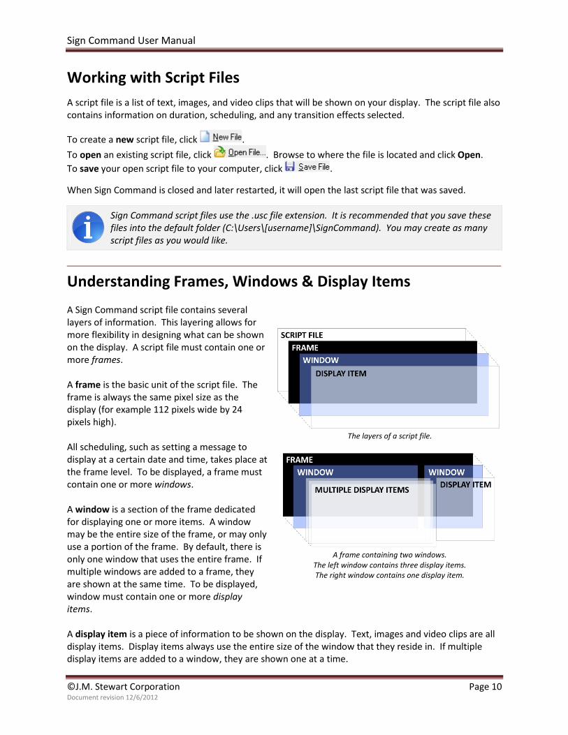
Understanding Frames, Windows & Display Items
A Sign Command script file contains several
layers of information. This layering allows for
more flexibility in designing what can be shown
on the display. A script file must contain one or
more frames.
A frame is the basic unit of the script file. The
frame is always the same pixel size as the
display (for example 112 pixels wide by 24
pixels high).
All scheduling, such as setting a message to
display at a certain date and time, takes place at
the frame level. To be displayed, a frame must
contain one or more windows.
A window is a section of the frame dedicated
for displaying one or more items. A window
may be the entire size of the frame, or may only
use a portion of the frame. By default, there is
only one window that uses the entire frame. If
multiple windows are added to a frame, they
are shown at the same time. To be displayed,
window must contain one or more display
items.
The layers of a script file.
A frame containing two windows.
The left window contains three display items.
The right window contains one display item.
A display item is a piece of information to be shown on the display. Text, images and video clips are all
display items. Display items always use the entire size of the window that they reside in. If multiple
display items are added to a window, they are shown one at a time.
Sign Command User Manual
©J.M. Stewart Corporation Page 11 Document revision 12/6/2012
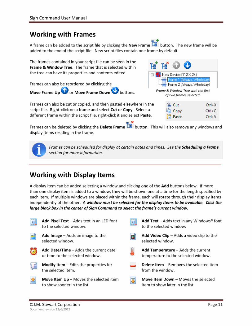
Working with Frames
A frame can be added to the script file by clicking the New Frame button. The new frame will be
added to the end of the script file. New script files contain one frame by default.
The frames contained in your script file can be seen in the
Frame & Window Tree. The frame that is selected within
the tree can have its properties and contents edited.
Frames can also be reordered by clicking the
Move Frame Up or Move Frame Down buttons.
Frame & Window Tree with the first
of two frames selected.
Frames can also be cut or copied, and then pasted elsewhere in the
script file. Right-click on a frame and select Cut or Copy. Select a
different frame within the script file, right-click it and select Paste.
Frames can be deleted by clicking the Delete Frame button. This will also remove any windows and
display items residing in the frame.
Frames can be scheduled for display at certain dates and times. See the Scheduling a Frame
section for more information.
Working with Display Items
A display item can be added selecting a window and clicking one of the Add buttons below. If more
than one display item is added to a window, they will be shown one at a time for the length specified by
each item. If multiple windows are placed within the frame, each will rotate through their display items
independently of the other. A window must be selected for the display items to be available. Click the
large black box in the center of Sign Command to select the frame’s current window.
Add Pixel Text – Adds text in an LED font
to the selected window.
Add Text – Adds text in any Windows® font
to the selected window.
Add Image – Adds an image to the
selected window.
Add Video Clip – Adds a video clip to the
selected window.
Add Date/Time – Adds the current date
or time to the selected window.
Add Temperature – Adds the current
temperature to the selected window.
Modify Item – Edits the properties for
the selected item.
Delete Item – Removes the selected item
from the window.
Move Item Up – Moves the selected item
to show sooner in the list.
Move Item Down – Moves the selected
item to show later in the list
Sign Command User Manual
©J.M. Stewart Corporation Page 12 Document revision 12/6/2012
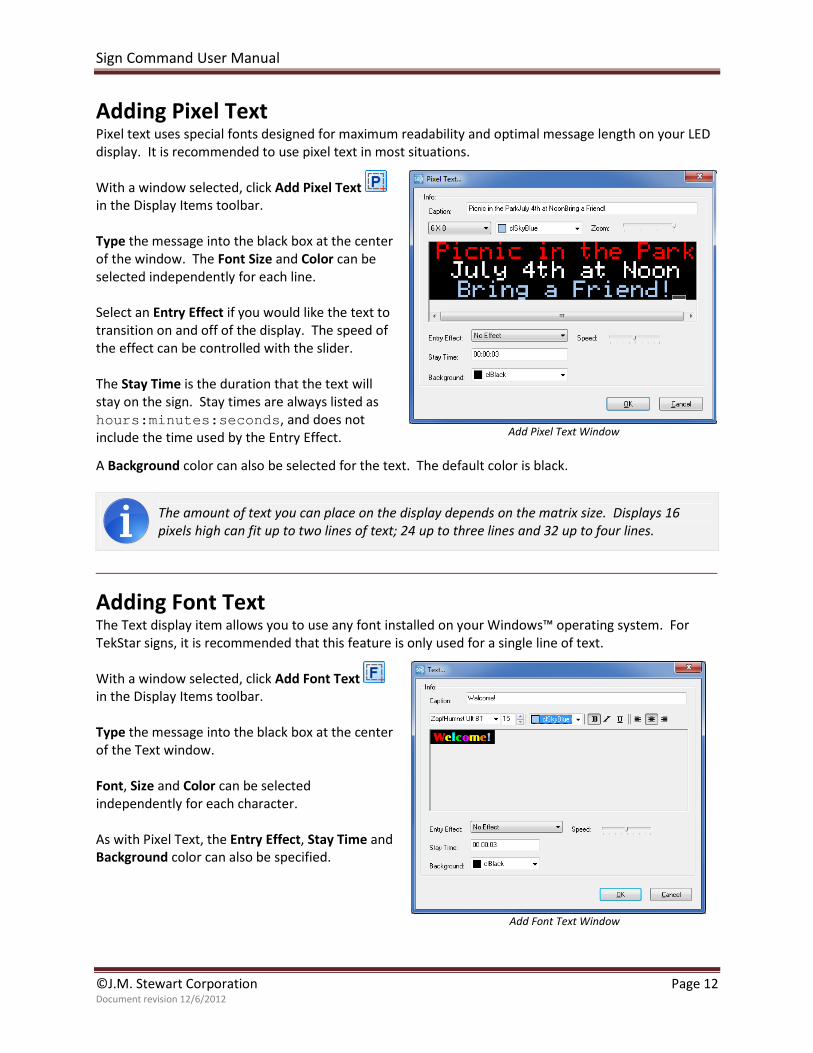
Adding Pixel Text Pixel text uses special fonts designed for maximum readability and optimal message length on your LED
display. It is recommended to use pixel text in most situations.
With a window selected, click Add Pixel Text
in the Display Items toolbar.
Type the message into the black box at the center
of the window. The Font Size and Color can be
selected independently for each line.
Select an Entry Effect if you would like the text to
transition on and off of the display. The speed of
the effect can be controlled with the slider.
The Stay Time is the duration that the text will
stay on the sign. Stay times are always listed as
hours:minutes:seconds, and does not
include the time used by the Entry Effect.
Add Pixel Text Window
A Background color can also be selected for the text. The default color is black.
The amount of text you can place on the display depends on the matrix size. Displays 16
pixels high can fit up to two lines of text; 24 up to three lines and 32 up to four lines.
Adding Font Text The Text display item allows you to use any font installed on your Windows™ operating system. For
TekStar signs, it is recommended that this feature is only used for a single line of text.
With a window selected, click Add Font Text
in the Display Items toolbar.
Type the message into the black box at the center
of the Text window.
Font, Size and Color can be selected
independently for each character.
As with Pixel Text, the Entry Effect, Stay Time and
Background color can also be specified.
Add Font Text Window
Sign Command User Manual
©J.M. Stewart Corporation Page 13 Document revision 12/6/2012
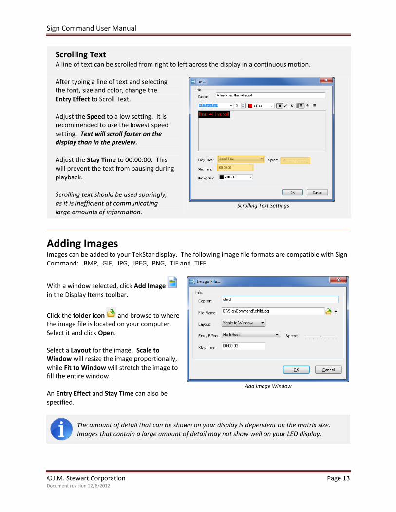
Scrolling Text A line of text can be scrolled from right to left across the display in a continuous motion.
After typing a line of text and selecting
the font, size and color, change the
Entry Effect to Scroll Text.
Adjust the Speed to a low setting. It is
recommended to use the lowest speed
setting. Text will scroll faster on the
display than in the preview.
Adjust the Stay Time to 00:00:00. This
will prevent the text from pausing during
playback.
Scrolling text should be used sparingly,
as it is inefficient at communicating
large amounts of information.
Scrolling Text Settings
Adding Images
Images can be added to your TekStar display. The following image file formats are compatible with Sign
Command: .BMP, .GIF, .JPG, .JPEG, .PNG, .TIF and .TIFF.
With a window selected, click Add Image
in the Display Items toolbar.
Click the folder icon and browse to where
the image file is located on your computer.
Select it and click Open.
Select a Layout for the image. Scale to
Window will resize the image proportionally,
while Fit to Window will stretch the image to
fill the entire window.
An Entry Effect and Stay Time can also be
specified.
Add Image Window
The amount of detail that can be shown on your display is dependent on the matrix size.
Images that contain a large amount of detail may not show well on your LED display.
Sign Command User Manual
©J.M. Stewart Corporation Page 14 Document revision 12/6/2012
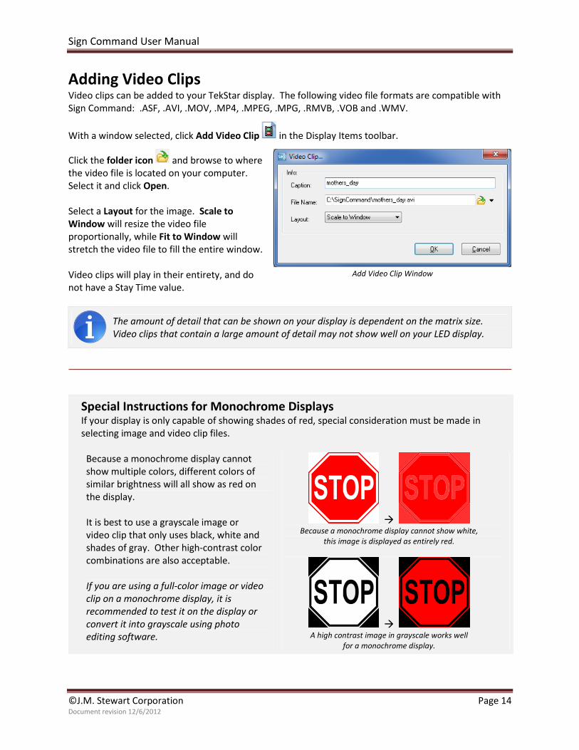
Adding Video Clips Video clips can be added to your TekStar display. The following video file formats are compatible with
Sign Command: .ASF, .AVI, .MOV, .MP4, .MPEG, .MPG, .RMVB, .VOB and .WMV.
With a window selected, click Add Video Clip in the Display Items toolbar.
Click the folder icon and browse to where
the video file is located on your computer.
Select it and click Open.
Select a Layout for the image. Scale to
Window will resize the video file
proportionally, while Fit to Window will
stretch the video file to fill the entire window.
Video clips will play in their entirety, and do
not have a Stay Time value.
Add Video Clip Window
The amount of detail that can be shown on your display is dependent on the matrix size.
Video clips that contain a large amount of detail may not show well on your LED display.
Special Instructions for Monochrome Displays If your display is only capable of showing shades of red, special consideration must be made in
selecting image and video clip files.
Because a monochrome display cannot
show multiple colors, different colors of
similar brightness will all show as red on
the display.
It is best to use a grayscale image or
video clip that only uses black, white and
shades of gray. Other high-contrast color
combinations are also acceptable.
If you are using a full-color image or video
clip on a monochrome display, it is
recommended to test it on the display or
convert it into grayscale using photo
editing software.
� Because a monochrome display cannot show white,
this image is displayed as entirely red.
�
A high contrast image in grayscale works well
for a monochrome display.
Sign Command User Manual
©J.M. Stewart Corporation Page 15 Document revision 12/6/2012
Adding Date & Time Sign Command allows you to include the current date and time within a window. The date and time are
derived from an internal clock within the display, which is updated from the computer running Sign
Command.
With a window selected, click Add Date/Time
in the Display Item toolbar.
Select your desired options. The text size will be adjusted
automatically to fit the information within the window.
Add Date/Time Window
The following formats are available for
date and time. The examples use the
date and time of Wednesday, July 4th
,
2012 at 9:30 PM.
Format Example
M/D/YYYY 7/4/2012
M/D/YY 7/4/12
MMM DD YYYY Jul 04 2012
MMMM DD July 04
WWWW Wednesday
YYYY-MM-DD 2012-07-04
DD-MMM-YY 04-Jul-12
h:mm AP 9:30 PM
HH:mm 21:30
If the clock is incorrect on your computer, the time or date may show incorrectly on the
display. It is recommended to use a time-syncing service on your computer to keep this
information accurate.
Adding Temperature Sign Command allows you to include the current temperature within a window. The temperature is
derived from a temperature probe attached to the sign.
With a window selected, click Add Temperature
in the Display Item toolbar.
Select a Scale of either Fahrenheit or Celsius.
Select your desired options. The text size will be
adjusted automatically to fit the information within
the window.
Add Temperature Window
Sign Command User Manual
©J.M. Stewart Corporation Page 16 Document revision 12/6/2012
Scheduling a Frame
Individual frames can be scheduled to be displayed during certain days and times. These frames will
begin showing at their scheduled start time, and end at the stop time. By default, scheduled frames will
be shown on the display along with any other frames scheduled for that time.
With a frame selected, click the button.
By default, frames are set to Always, Every
Day, Wholeday. These frames will loop
continuously on the display.
There must be at least one frame in the script
file that has these settings. This ensures that
there is always something showing on the
display.
To set a frame to only be displayed during a
certain time, change the Time Type to Time
and enter in a Start and Stop value.
To set a frame to only be displayed during a
certain day of the week, change the Sub Type
to Every Week and select the days. This
setting can be used in combination with the
Time Type to only show the frame during
certain times on the selected days.
A frame scheduled to always be shown will
loop continuously on the display.
A frame scheduled to be displayed every day between
8:00 AM and 9:00 AM.
A frame scheduled to be displayed every weekday
between 3:00 PM and 6:00 PM.
Sign Command User Manual
©J.M. Stewart Corporation Page 17 Document revision 12/6/2012
To set a frame to only be displayed during a
certain day of the month, change the Sub
Type to Every Month and select the days.
This setting can be used in combination with
the Time Type to only show the frame during
certain times on the selected days.
Frames can also be set to only show between
certain dates. Change the Date Type to Date
and select a Start and Stop value. This setting
can be used in combination with Sub Type
and Time Type to only show the frame during
certain days and times between the selected
dates.
By default, a scheduled frame will rotate in
with other scheduled frames and the Always,
Wholeday frame. However, there may be
instances when you only want to show a
certain frame for a set amount of time.
To do this, change the Play time to the
duration in hours:minutes:seconds.
The frame will now show exclusively for the
set amount of time. The Stop time is not
relevant assuming that it occurs before the
end of the Play time.
A frame scheduled to be displayed on the 1
st and 15th
of every month, throughout the whole day.
A frame scheduled to be displayed every day from
12/1/2012 to 12/31/2012, between 5:00 PM and 11:00 PM.
A frame scheduled to play exclusively for one hour every day
starting at 8:00 AM.
Previewing a Frame
Once the windows and display items are added and configured, click to view how the
frame will appear on the display. Once you are done previewing the frame, click the X in the top right of
the Preview window to close it.
Sign Command User Manual
©J.M. Stewart Corporation Page 18 Document revision 12/6/2012
Transmitting to the Display
The following feature is only available for displays with a network connection. If your sign is
not network connected, use the Exporting to USB method to transmit your script file. If the
device is not detected, you will not be able to transmit your script to the display.
Click to open the Send to Sign window. If you
have not yet saved your script file to the computer, you will be
prompted to save it.
If not already selected, place a checkmark next to the display
you wish to change and click Send. The log will post each step
of the transmission.
Once complete, click Close. The script file will now be playing
on the display.
Send to Sign Window
Once the file transfer is complete, it is not required to leave the Sign Command program
running or your computer on.
Exporting to USB
The USB drive that you use must not contain other data, and must have enough storage
space for all video clips and images used in the script file.
Plug in your USB drive into an open USB port on your computer. When the computer recognizes the
USB drive, make note of the drive letter.
Click in the top toolbar.
Click the folder icon next to the Export To box. Select your
USB drive from the folder list. Click OK in the Browse for Folder
window, and then click Apply to export the file.
You will be alerted if the export was successful. Close the Export
window and remove your USB drive from the computer.
Export Window
Plug in the USB drive into the USB port on the sign. The transfer of data will be automatic, and the file
will begin playing momentarily.
Once the new file begins playing, the file transfer is complete. It is not required to leave the
USB drive in the sign.
Sign Command User Manual
©J.M. Stewart Corporation Page 19 Document revision 12/6/2012
Working with Multiple Windows
By default, there is only one window per frame that takes up the entire size of the frame. There may be
instances, however, where you may wish to have multiple windows within the frame. This allows for
displaying multiple items at the same time; for example, showing text next to an image, or the
temperature next to the time.
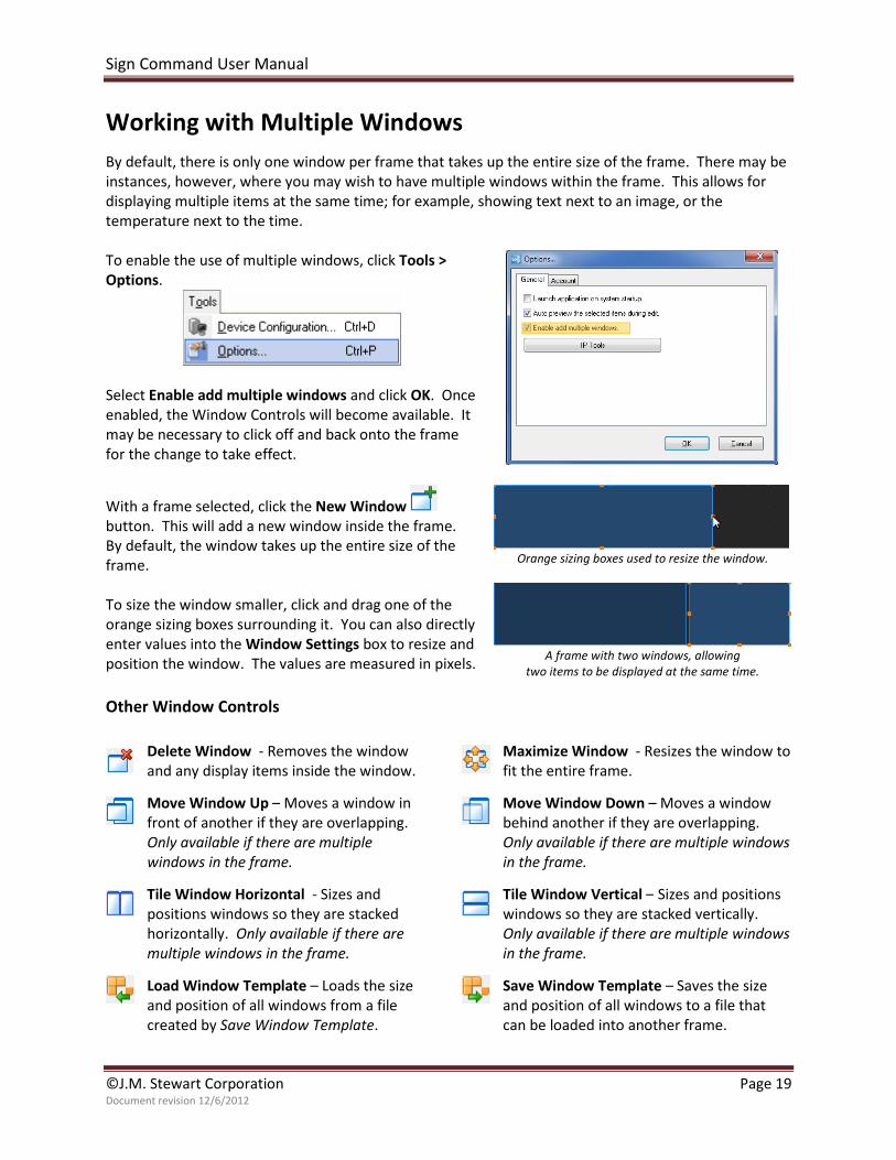
To enable the use of multiple windows, click Tools >
Options.
Select Enable add multiple windows and click OK. Once
enabled, the Window Controls will become available. It
may be necessary to click off and back onto the frame
for the change to take effect.
With a frame selected, click the New Window
button. This will add a new window inside the frame.
By default, the window takes up the entire size of the
frame.
To size the window smaller, click and drag one of the
orange sizing boxes surrounding it. You can also directly
enter values into the Window Settings box to resize and
position the window. The values are measured in pixels.
Orange sizing boxes used to resize the window.
A frame with two windows, allowing
two items to be displayed at the same time.
Other Window Controls
Delete Window - Removes the window
and any display items inside the window.
Maximize Window - Resizes the window to
fit the entire frame.
Move Window Up – Moves a window in
front of another if they are overlapping.
Only available if there are multiple
windows in the frame.
Move Window Down – Moves a window
behind another if they are overlapping.
Only available if there are multiple windows
in the frame.
Tile Window Horizontal - Sizes and
positions windows so they are stacked
horizontally. Only available if there are
multiple windows in the frame.
Tile Window Vertical – Sizes and positions
windows so they are stacked vertically.
Only available if there are multiple windows
in the frame.
Load Window Template – Loads the size
and position of all windows from a file
created by Save Window Template.
Save Window Template – Saves the size
and position of all windows to a file that
can be loaded into another frame.
Sign Command User Manual
©J.M. Stewart Corporation Page 20 Document revision 12/6/2012
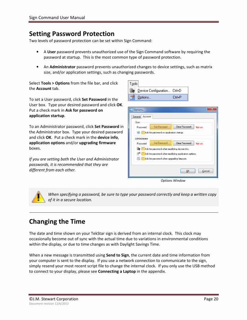
Setting Password Protection Two levels of password protection can be set within Sign Command:
• A User password prevents unauthorized use of the Sign Command software by requiring the
password at startup. This is the most common type of password protection.
• An Administrator password prevents unauthorized changes to device settings, such as matrix
size, and/or application settings, such as changing passwords.
Select Tools > Options from the file bar, and click
the Account tab.
To set a User password, click Set Password in the
User box. Type your desired password and click OK.
Put a check mark in Ask for password on
application startup.
To an Administrator password, click Set Password in
the Administrator box. Type your desired password
and click OK. Put a check mark in the device info,
application options and/or upgrading firmware
boxes.
If you are setting both the User and Administrator
passwords, it is recommended that they are
different from each other.
Options Window
When specifying a password, be sure to type your password correctly and keep a written copy
of it in a secure location.
Changing the Time
The date and time shown on your TekStar sign is derived from an internal clock. This clock may
occasionally become out of sync with the actual time due to variations in environmental conditions
within the display, or due to time changes as with Daylight Savings Time.
When a new message is transmitted using Send to Sign, the current date and time information from
your computer is sent to the display. If you use a network connection to communicate to the sign,
simply resend your most recent script file to change the internal clock. If you only use the USB method
to connect to your display, please see Connecting a Laptop in the appendix.
Sign Command User Manual
©J.M. Stewart Corporation Page 21 Document revision 12/6/2012
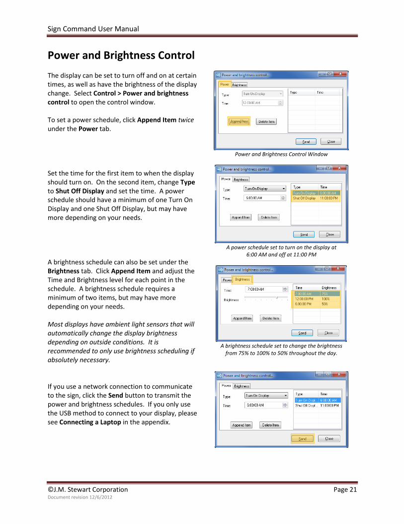
Power and Brightness Control
The display can be set to turn off and on at certain
times, as well as have the brightness of the display
change. Select Control > Power and brightness
control to open the control window.
To set a power schedule, click Append Item twice
under the Power tab.
Set the time for the first item to when the display
should turn on. On the second item, change Type
to Shut Off Display and set the time. A power
schedule should have a minimum of one Turn On
Display and one Shut Off Display, but may have
more depending on your needs.
A brightness schedule can also be set under the
Brightness tab. Click Append Item and adjust the
Time and Brightness level for each point in the
schedule. A brightness schedule requires a
minimum of two items, but may have more
depending on your needs.
Most displays have ambient light sensors that will
automatically change the display brightness
depending on outside conditions. It is
recommended to only use brightness scheduling if
absolutely necessary.
If you use a network connection to communicate
to the sign, click the Send button to transmit the
power and brightness schedules. If you only use
the USB method to connect to your display, please
see Connecting a Laptop in the appendix.
Power and Brightness Control Window
A power schedule set to turn on the display at
6:00 AM and off at 11:00 PM
A brightness schedule set to change the brightness
from 75% to 100% to 50% throughout the day.
Sign Command User Manual
©J.M. Stewart Corporation Page 22 Document revision 12/6/2012
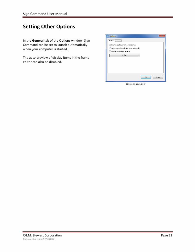
Setting Other Options
In the General tab of the Options window, Sign
Command can be set to launch automatically
when your computer is started.
The auto preview of display items in the frame
editor can also be disabled.
Options Window
Sign Command User Manual
©J.M. Stewart Corporation Page 23 Document revision 12/6/2012
Appendix
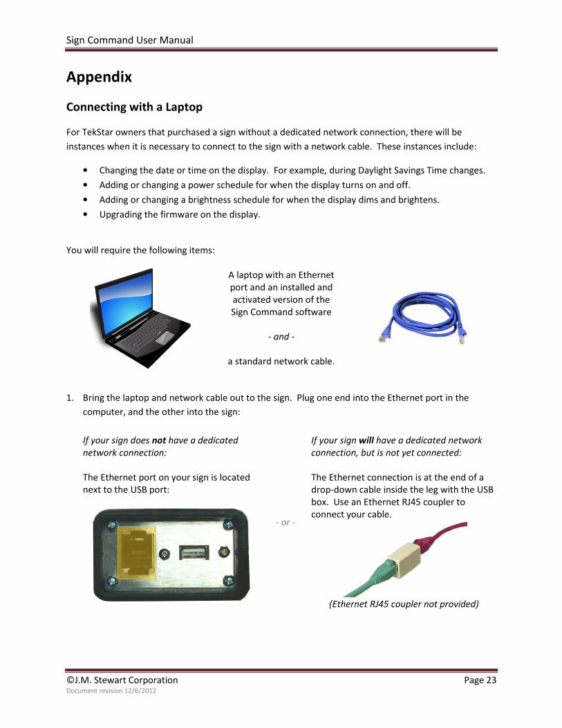
Connecting with a Laptop
For TekStar owners that purchased a sign without a dedicated network connection, there will be
instances when it is necessary to connect to the sign with a network cable. These instances include:
• Changing the date or time on the display. For example, during Daylight Savings Time changes.
• Adding or changing a power schedule for when the display turns on and off.
• Adding or changing a brightness schedule for when the display dims and brightens.
• Upgrading the firmware on the display.
You will require the following items:
A laptop with an Ethernet
port and an installed and
activated version of the
Sign Command software
- and -
a standard network cable.
1. Bring the laptop and network cable out to the sign. Plug one end into the Ethernet port in the
computer, and the other into the sign:
If your sign does not have a dedicated
network connection:
The Ethernet port on your sign is located
next to the USB port:
- or -
If your sign will have a dedicated network
connection, but is not yet connected:
The Ethernet connection is at the end of a
drop-down cable inside the leg with the USB
box. Use an Ethernet RJ45 coupler to
connect your cable.
(Ethernet RJ45 coupler not provided)
Sign Command User Manual
©J.M. Stewart Corporation Page 24 Document revision 12/6/2012
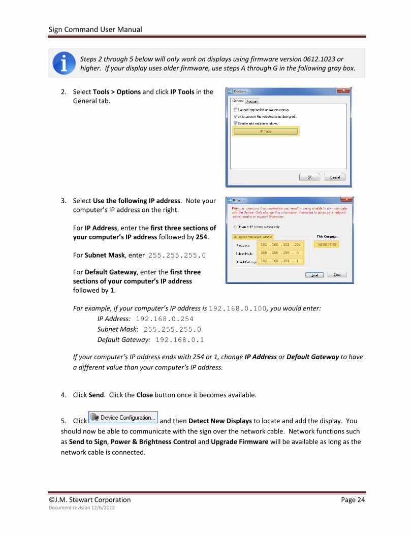
Steps 2 through 5 below will only work on displays using firmware version 0612.1023 or
higher. If your display uses older firmware, use steps A through G in the following gray box.
2. Select Tools > Options and click IP Tools in the
General tab.
3. Select Use the following IP address. Note your
computer’s IP address on the right.
For IP Address, enter the first three sections of
your computer’s IP address followed by 254.
For Subnet Mask, enter 255.255.255.0
For Default Gateway, enter the first three
sections of your computer’s IP address
followed by 1.
For example, if your computer’s IP address is 192.168.0.100, you would enter:
IP Address: 192.168.0.254
Subnet Mask: 255.255.255.0
Default Gateway: 192.168.0.1
If your computer’s IP address ends with 254 or 1, change IP Address or Default Gateway to have
a different value than your computer’s IP address.
4. Click Send. Click the Close button once it becomes available.
5. Click and then Detect New Displays to locate and add the display. You
should now be able to communicate with the sign over the network cable. Network functions such
as Send to Sign, Power & Brightness Control and Upgrade Firmware will be available as long as the
network cable is connected.
Sign Command User Manual
©J.M. Stewart Corporation Page 25 Document revision 12/6/2012
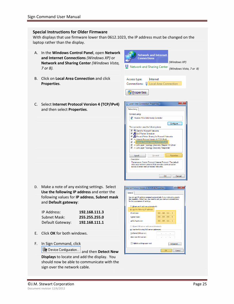
Special Instructions for Older Firmware With displays that use firmware lower than 0612.1023, the IP address must be changed on the
laptop rather than the display.
A. In the Windows Control Panel, open Network
and Internet Connections (Windows XP) or
Network and Sharing Center (Windows Vista,
7 or 8).
B. Click on Local Area Connection and click
Properties.
C. Select Internet Protocol Version 4 (TCP/IPv4)
and then select Properties.
D. Make a note of any existing settings. Select
Use the following IP address and enter the
following values for IP address, Subnet mask
and Default gateway:
IP Address:
Subnet Mask:
Default Gateway:
192.168.111.3
255.255.255.0
192.168.111.1
E. Click OK for both windows.
F. In Sign Command, click
and then Detect New
Displays to locate and add the display. You
should now be able to communicate with the
sign over the network cable.
(Windows XP)
(Windows Vista, 7 or 8)
Sign Command User Manual
©J.M. Stewart Corporation Page 26 Document revision 12/6/2012
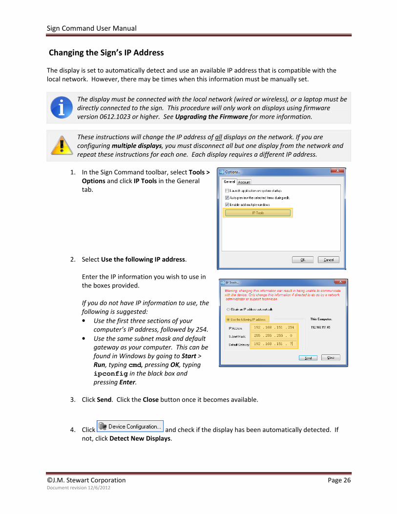
Changing the Sign’s IP Address
The display is set to automatically detect and use an available IP address that is compatible with the
local network. However, there may be times when this information must be manually set.
The display must be connected with the local network (wired or wireless), or a laptop must be
directly connected to the sign. This procedure will only work on displays using firmware
version 0612.1023 or higher. See Upgrading the Firmware for more information.
These instructions will change the IP address of all displays on the network. If you are
configuring multiple displays, you must disconnect all but one display from the network and
repeat these instructions for each one. Each display requires a different IP address.
1. In the Sign Command toolbar, select Tools >
Options and click IP Tools in the General
tab.
2. Select Use the following IP address.
Enter the IP information you wish to use in
the boxes provided.
If you do not have IP information to use, the
following is suggested:
• Use the first three sections of your
computer’s IP address, followed by 254.
• Use the same subnet mask and default
gateway as your computer. This can be
found in Windows by going to Start >
Run, typing cmd, pressing OK, typing
ipconfig in the black box and
pressing Enter.
3. Click Send. Click the Close button once it becomes available.
4. Click and check if the display has been automatically detected. If
not, click Detect New Displays.
Sign Command User Manual
©J.M. Stewart Corporation Page 27 Document revision 12/6/2012
Upgrading the Firmware Firmware is simply the software that runs inside of the display. At times the firmware may require an update, such
as when upgrading from version 0.20 to version 1.10 of Sign Command. It is recommended to upgrade the
firmware only when required to do so. The Update Firmware button in Sign Command is for future development
and is not currently used.
You must first have the appropriate firmware files downloaded and available on your computer. These files are
available on the support website at www.stewartsigns.com/support/tekstar or from a support technician.
The display must be connected with the local network (wired or wireless), or a laptop must be directly
connected to the sign. Please see Connecting with a Laptop for more information.
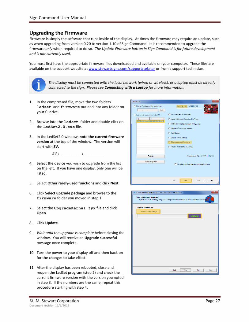
1. In the compressed file, move the two folders
ledset and firmware out and into any folder on
your C: drive.
2. Browse into the ledset folder and double-click on
the LedSet2.0.exe file.
3. In the LedSet2.0 window, note the current firmware
version at the top of the window. The version will
start with SV.
SV: ________:________
4. Select the device you wish to upgrade from the list
on the left. If you have one display, only one will be
listed.
5. Select Other rarely-used functions and click Next.
6. Click Select upgrade package and browse to the
firmware folder you moved in step 1.
7. Select the UpgradeKernal.fyx file and click
Open.
8. Click Update.
9. Wait until the upgrade is complete before closing the
window. You will receive an Upgrade successful
message once complete.
10. Turn the power to your display off and then back on
for the changes to take effect.
11. After the display has been rebooted, close and
reopen the LedSet program (step 2) and check the
current firmware version with the version you noted
in step 3. If the numbers are the same, repeat this
procedure starting with step 4.
Sign Command User Manual
©J.M. Stewart Corporation Page 28 Document revision 12/6/2012
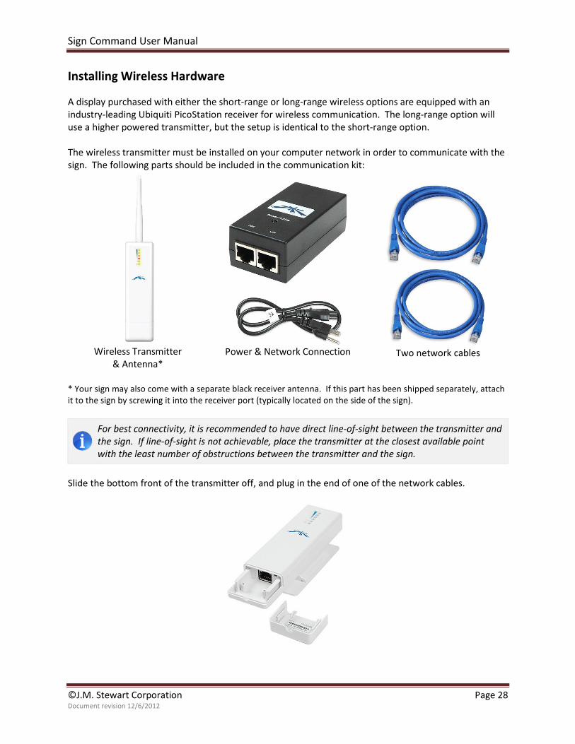
Installing Wireless Hardware
A display purchased with either the short-range or long-range wireless options are equipped with an
industry-leading Ubiquiti PicoStation receiver for wireless communication. The long-range option will
use a higher powered transmitter, but the setup is identical to the short-range option.
The wireless transmitter must be installed on your computer network in order to communicate with the
sign. The following parts should be included in the communication kit:
Wireless Transmitter
& Antenna*
Power & Network Connection
Two network cables
* Your sign may also come with a separate black receiver antenna. If this part has been shipped separately, attach
it to the sign by screwing it into the receiver port (typically located on the side of the sign).
For best connectivity, it is recommended to have direct line-of-sight between the transmitter and
the sign. If line-of-sight is not achievable, place the transmitter at the closest available point
with the least number of obstructions between the transmitter and the sign.
Slide the bottom front of the transmitter off, and plug in the end of one of the network cables.
Sign Command User Manual
©J.M. Stewart Corporation Page 29 Document revision 12/6/2012
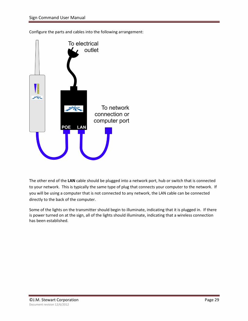
Configure the parts and cables into the following arrangement:
The other end of the LAN cable should be plugged into a network port, hub or switch that is connected
to your network. This is typically the same type of plug that connects your computer to the network. If
you will be using a computer that is not connected to any network, the LAN cable can be connected
directly to the back of the computer.
Some of the lights on the transmitter should begin to illuminate, indicating that it is plugged in. If there
is power turned on at the sign, all of the lights should illuminate, indicating that a wireless connection
has been established.
Sign Command User Manual
©J.M. Stewart Corporation Page 30 Document revision 12/6/2012
Troubleshooting a Network Connection If Sign Command does not recognize the display as being on the network, there are several places where
the problem could be occurring. Confirm that each step below is complete before moving to the next.
□ There is power at the sign site and to the display.
Make sure all electrical breakers are turned on. The display should be showing a message (or listen for the
internal fans running inside of the display if no message is showing).
□ The display is connected to the local network.
If the display has a wired connection:
□ One end of the Ethernet cable is connected to
the Ethernet cable located within the leg of the
sign (the same leg that has the USB box). See
the sign installation guide if you require
instructions on connecting these cables.
□ The other end of the Ethernet cable is plugged
into a hub or switch that is connected to your
network. Lights on the hub or switch show a
connection.
If the display has a wireless connection:
□ The black receiving antenna is attached to the
sign.
□ The wireless transmitter is configured and
connected to the network as per the
instructions in Installing Wireless Hardware,
and lights are showing on the transmitter.
□ The display has an IP address that is compatible with the local network.
Follow the instructions in the Changing the Sign’s IP Address chapter and select an IP address that will work
with your local network. If you have tried this step before and have been unsuccessful, there may be a
conflict with another device. Try changing the last portion IP address to a different number.
□ The display is reachable through the PING utility.
1. In Windows, click the Start button and select Run.
2. Type cmd and click OK.
3. In the black window, type ping, a space, and then the IP address that was set for the display. For
example, if the IP address of the display was set to 192.168.0.254, you would type: ping 192.168.0.254
4. If successful, the packets sent should equal the packets received. If not successful, you will receive
a “Destination host unreachable” error.
5. If you receive this error, try changing the IP address per the prior checklist item above.
6. If you have attempted changing the IP address several times and cannot complete this step, there
may be a hardware issue with your display. Contact a support technician for assistance.
□ The display is using the most up-to-date firmware.
Download and install the most recent firmware per the Upgrading the Firmware chapter.
□ The computer is using the most up-to-date version of Sign Command.
Download and install the most recent version of Sign Command per the Installing the Software chapter.
□ The device can be found in Sign Command.
In the Device Configuration window, click Detect New Displays.
Sign Command User Manual
©J.M. Stewart Corporation Page 31 Document revision 12/6/2012
Troubleshooting a USB Drive
For maximum compatibility, it is recommended to only use the USB drive that was supplied with the
display. Other USB drives may also work depending on their settings and other factors. If you have a
USB drive that is not communicating with the display, performing a reformat may correct the issue.
The USB drive must only contain the Sign Command files to be used with the display. It is
recommended to try deleting all files on the drive and Export to USB again before continuing.
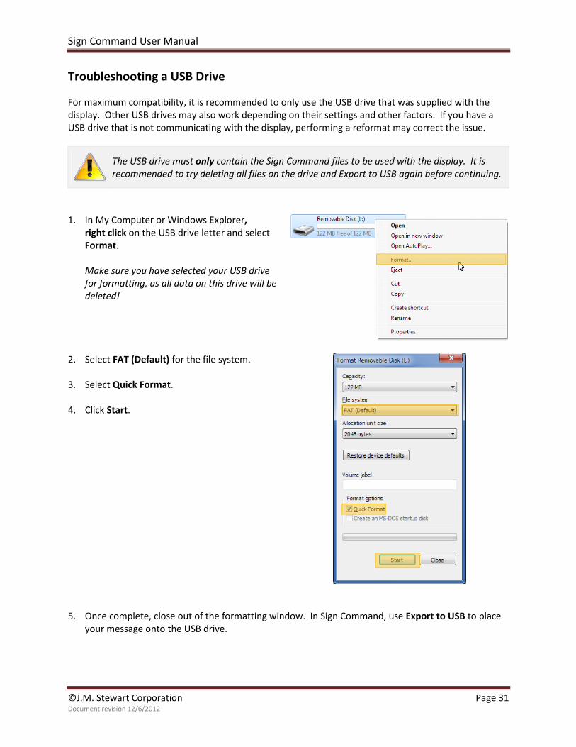
1. In My Computer or Windows Explorer,
right click on the USB drive letter and select
Format.
Make sure you have selected your USB drive
for formatting, as all data on this drive will be
deleted!
2. Select FAT (Default) for the file system.
3. Select Quick Format.
4. Click Start.
5. Once complete, close out of the formatting window. In Sign Command, use Export to USB to place
your message onto the USB drive.