Embed Size (px)
Citation preview

2300 SYSTEM
Signal Conditioning Amplifier
2310B
Instruction Manual
Vishay Micro-Measurements
P.O. Box 27777 Raleigh, NC 27611
United States Telephone +1-919-365-3800
FAX +1-919-365-3945 E-mail: [email protected]
www.vishaymg.com
Oct 2009 130-000137

Copyright Vishay Micro-Measurements, 1995-2009 All Rights Reserved.
INSTRUCTION MANUAL
MODEL 2310B
SIGNAL CONDITIONING AMPLIFIER
1.0 DESCRIPTION............................................................................................................................................................... 3 1.1 GENERAL ........................................................................................................................................................... 3 1.2 SIGNIFICANT FEATURES .............................................................................................................................. 3
2.0 SPECIFICATIONS......................................................................................................................................................... 3 2.1 2310 SIGNAL CONDITIONING AMPLIFIER................................................................................................ 3 2.2 2350 RACK ADAPTER ...................................................................................................................................... 4 2.3 2360 PORTABLE ENCLOSURE....................................................................................................................... 4
3.0 CONTROLS .................................................................................................................................................................... 5 3.1 2310 FRONT PANEL.......................................................................................................................................... 5 3.2 2310 REAR PANEL ............................................................................................................................................ 6
4.0 OPERATING PROCEDURE ........................................................................................................................................ 7 4.1 SETUP AND AC POWER .................................................................................................................................. 7 4.2 GAGE INPUT CONNECTIONS ....................................................................................................................... 7 4.3 MILLIVOLT INPUTS ........................................................................................................................................ 8 4.4 WIRING CONSIDERATIONS .......................................................................................................................... 8 4.5 OUTPUT CONNECTIONS................................................................................................................................ 9 4.7 FILTER OUTPUT SELECTOR ...................................................................................................................... 10 4.8 EXCITATION ................................................................................................................................................... 10 4.9 AMPLIFIER BALANCE.................................................................................................................................. 11 4.10 BRIDGE BALANCE......................................................................................................................................... 11 4.11 BATTERY TEST .............................................................................................................................................. 11 4.12 GAIN .................................................................................................................................................................. 11 4.13 FILTER.............................................................................................................................................................. 12 4.14 DYNAMIC TESTING ...................................................................................................................................... 13 4.15 TAPE PLAYBACK ........................................................................................................................................... 13 4.16 REMOTE-OPERATION RELAYS................................................................................................................. 14 4.17 QUARTER-BRIDGE NONLINEARITY........................................................................................................ 14
5.0 SHUNT CALIBRATION ............................................................................................................................................. 14 5.1 INTRODUCTION............................................................................................................................................. 14 5.2 SHUNT CALIBRATION COMPONENTS IN 2310....................................................................................... 15 5.3 SHUNT CALIBRATION — STRESS ANALYSIS......................................................................................... 15 5.4 TRANSDUCERS............................................................................................................................................... 16 5.5 STANDARD CALIBRATION RESISTORS .................................................................................................. 18
6.0 ACTIVE FILTER ......................................................................................................................................................... 19 6.1 FILTER CHARACTERISTICS ...................................................................................................................... 19
7.0 MAINTENANCE .......................................................................................................................................................... 20 7.1 ADJUSTMENTS ............................................................................................................................................... 20 7.2 BATTERY REPLACEMENT.......................................................................................................................... 22 7.3 COMPONENT REPLACEMENT................................................................................................................... 22 7.4 FUSE REPLACEMENT................................................................................................................................... 23
APPENDIX............................................................................................................................................................................ 23
WARRANTY ........................................................................................................................................................................ 24

- 2 -
Complete 10-Channel 2300 System
2310 Signal Conditioning Amplifier
Module with Stabilizer Accessory
4-channel System in 2360 Portable Enclosure
2350 10-Channel Rack Adapter

- 3 -
1.1 GENERAL
The 2300 Series instruments comprise a versatile multi-
channel system for conditioning and amplifying low-level
signals from strain gages (or strain gage based transducers)
for display or recording on external equipment. Each 2310B
Signal Conditioning Amplifier is separately powered and
electrically isolated from all others (and can be powered with
a separate line cord), although groups of amplifiers are
normally inserted into a multi-channel rack adapter or
portable enclosure.
The Model 2350 Rack Adapter accepts up to ten 2310B
Amplifiers for mounting in a standard 19-in (483-mm) rack;
the Model 2360 Portable Enclosure accepts up to four 2310B
Amplifiers for more portable use.
Each Model 2310B Amplifier incorporates precision high-
stability bridge completion resistors and dummy gages, and
four shunt-calibration resistors, and is complete and ready for
use as delivered — only ac power is required via the Portable
Enclosure, Rack Adapter or separate ac line cord. Input and
output connectors are supplied with each amplifier.
1.2 SIGNIFICANT FEATURES
The 2300 Series is designed to provide features essential for
accurate stress analysis data in a broad range of measurement
applications. Principal features include:
• Fully adjustable calibrated gain from 1 to 11 000.
• Accepts all strain gage inputs (foil or piezoresistive),
potentiometers, DCDT’s, etc.
• Bridge excitation from 0.7 to 15Vdc (11 steps) plus 0.2
to 7 Volts continuously variable.
• Input impedance above 100 megohms.
• Two simultaneous buffered outputs: ±10V, ±1.4V (for
tape recorders).
• Wide band operation exceeding 60 kHz, -0.5 dB at all
gains and output levels.
• Four-frequency active 6-pole filter (10 to 10 000 Hz).
• Dual-range (±5000 and ±25000µε) automatic bridge
balance, with keep-alive power to preserve balance for
months without external power.
• Dual-polarity two-step double-shunt calibration.
• Optional remote calibration and auto balance reset.
• Playback mode to filter and observe or re-record
previously recorded magnetic tape data.
• And many other convenience features.
All specifications are nominal or typical at +23°C unless
noted. Performance may be degraded in the presence of
high-level electromagnetic fields.
2.1 2310B SIGNAL CONDITIONING AMPLIFIER
INPUT:
Strain gages: quarter, half or full bridge (50 to
1000Ω). Built-in 120Ω and 350Ω dummy gages;
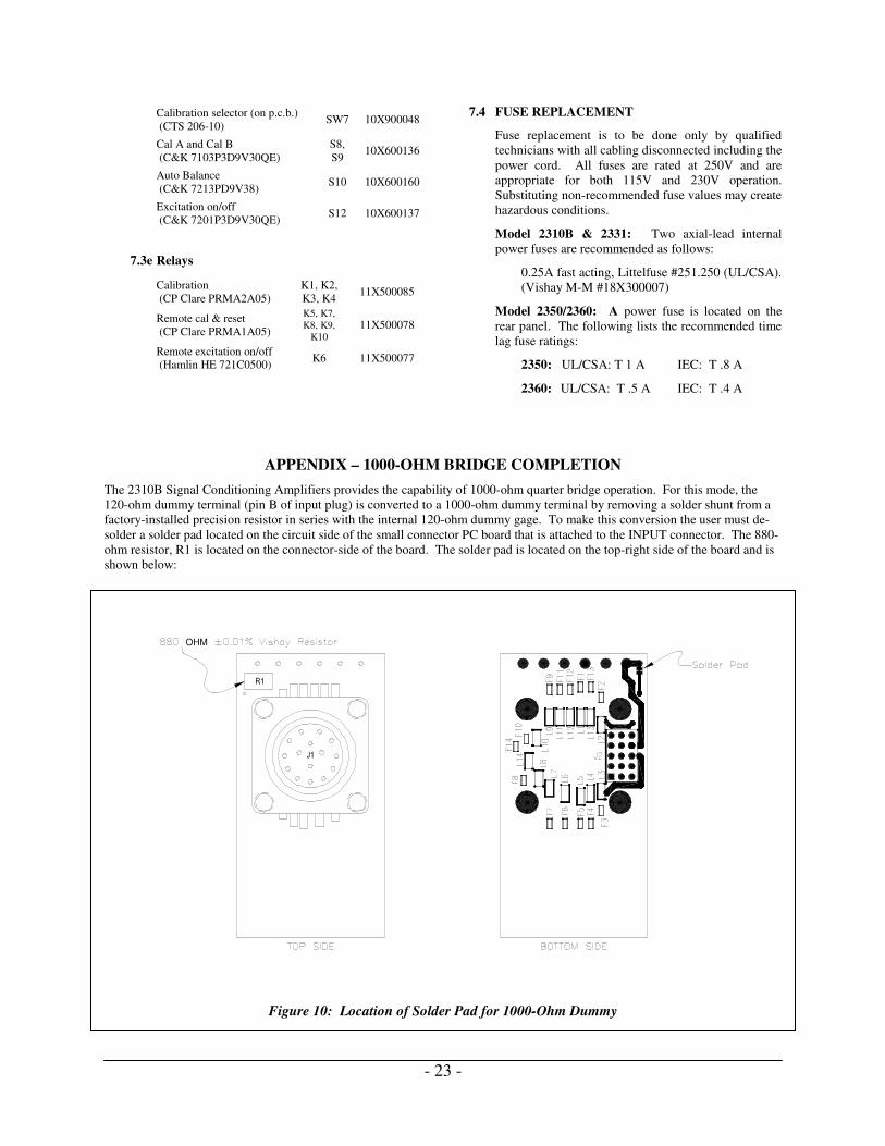
1000Ω dummy capability. See Appendix, page 23.
Transducers: foil or piezoresistive strain gage
types; DCDT displacement transducers;
potentiometers.
EXCITATION:
Eleven settings: 0.7, 1, 1.4, 2, 2.7, 3.5, 5, 7, 10, 12
and 15 Vdc ±1% max. One variable setting : 0.2 to
7 Vdc
Current: 0-100 mA, min, limited at 175 mA, max.
Regulation (0-100 mA ±10% line change): ±0.5
mV ±0.04%, max measured at remote sense points.
(Local sense: -5 mV, typical, @ 100 mA, measured
at plug.)
Remote sense error: 0.0005% per ohm of lead
resistance (350Ω load).
Noise and ripple: 0.05% p-p, max (dc to 10 kHz).
Stability: ±0.02%/°C.
Level: normally symmetrical about ground; either
side may be grounded with no effect on
performance.
BRIDGE BALANCE:
Method: counter-emf injection at pre-amp;
automatic electronic; dual range; can be disabled on
front panel.
Ranges (auto ranging):
±5000µε (±1% bridge unbalance or ±2.5 m V/V),
resolution 2.5µε (0.0012 mV/V).
±25 000µε (±5% bridge unbalance or ±12.5 mV/V),
resolution 12.5µε (0.006 mV/V).
Balance time: 2 seconds, typical.
Manual vernier balance range: 100µε (0.050
mV/V).
Interaction: essentially independent of excitation
and amplifier gain.
Storage: non-volatile digital storage without line
power for up to two years.
SHUNT CALIBRATION:
Circuit (two-level, dual polarity): Single-shunt
(for stress analysis) across any bridge arm,
including dummy gage.
Double-shunt (for transducers) across opposite
bridge arms.
Provision for four dedicated leads to shunt external
arms.
1.0 DESCRIPTON
2.0 SPECIFICATIONS

- 4 -
CAL circuit selected by switches on p.c. board.
Standard factory-installed resistors (±0.1%)
simulate:
±200 and ±1000µε @ GF=2 across dummy
half bridge;
±1000µε @ GF=2 across dummy gage (120Ω
and 350Ω).
±1 mV/V (double shunt) for 350Ω transducer.
Remote-operation relays (Option Y): four relays
(plus remote-reset relay for bridge balance and
relay for excitation on/off). Each relay requires 10
mA @ 5 Vdc, except excitation on/off 25 mA.
AMPLIFIER
Gain: 1 to 11 000 continuously variable. Direct-
reading, ±1% max. 10-turn counting knob (X1 to
X11) plus decade multiplier (X1 to X1000)
Frequency response, all gains full output:
dc coupled: dc to 125 kHz, -3 dB max.
dc to 55 kHz, -0.5 dB max.
ac coupled: 1.7Hz typ. to 125 kHz, -3 dB max.
Frequency response versus gain, full output:
GAIN -0.5db -3 db
1-11 120 kHz 300 kHz
10-110 90 kHz 230 kHz
100-1100 70 kHz 150 kHz
1000-11000 55 kHz 125 kHz
Input impedance: 100 MΩ, min, differential or
common-mode, including bridge balance circuit.
Bias current: ±40 nA, typical max., each input.
Source impedance: 0 to 1000Ω each input.
Common-mode voltage: ±10V.
Common-mode rejection (gain over X100):
Shorted input: 100dB, min, at dc to 60 Hz;
90 dB, min, dc to 1 kHz;
350Ω balanced input: 90 dB, typical, dc to 1
kHz.
Stability (gain over X100): ±2 µV/°C, max, RTI
(referred to input).
Noise (gain over X100, all outputs):
0.01 to 10 Hz: 1 µV p-p RTI.
0.5 to 125 kHz: 6 µVrms, max, RTI.
FILTER:
Characteristic: Low-pass active six-pole Butterworth standard.
Frequencies (-3 ±1 dB): 10, 100, 1000 and 10 000
Hz and wide-band.
Outputs filtered: either one or both (switch-
selected on p.c. board).
AMPLIFIER OUTPUTS:
Standard output: ±10V @ 5 mA, min.
Tape output: ±1.414V (1 Vrms) @ 5 mA, min.
Linearity @ dc: ±0.02%.
Either output can be short-circuited with no effect
on the other.
PLAYBACK:
Input: ±1.414V full scale; input impedance 20 kΩ.
Gain: X1 to tape output; X7.07 to standard output.
Filter selection: as specified above.
Outputs: Both as specified above.
OPERATING ENVIRONMENT:
Temperature: 0° to +50°C.
Humidity: 10 to 90%, non-condensing.
POWER:
105 to 125V or 210 to 250V (switch-selected),
50/60 Hz, 10 watts, max.
Keep-alive supply (for bridge balance): Lithium
3.6V, 1/2AA or equal. Shelf life approximately
two years.
SIZE & WEIGHT:
Panel: 8.75 H x 1.706 W in (222.2 x 43.3 mm).
Case depth behind panel: 15.9 in (404 mm).
Weight: 6 lb (2.7 kg).
2.2 2350 RACK ADAPTER
APPLICATION:
Fits standard 19-in (483-mm) electronic equipment
rack.
Accepts up to ten 2310B Amplifiers. AC line
completely wired.
Wiring for remote calibration with Option Y.
POWER:
115 or 230 Vac switch selected in amplifiers, 50/60
Hz, 100 Watts max.
SIZE & WEIGHT:
8.75 H x 19 W x 19.06 D overall (222 x 483 x 484
mm).
13.5 lb (6.1 kg).
2.3 2360 PORTABLE ENCLOSURE
DESCRIPTION:
Enclosure to accept up to four 2310B Amplifiers.

- 5 -
AC wiring complete.
Wiring for remote calibration with Option Y.
POWER:
115 or 230 Vac switch selected in amplifiers, 50/60
Hz, 40 Watts max.
SIZE & WEIGHT:
9.06 H x 7.20 W x 18.90 D in
(229 x 183 x 480 mm)
6.75 lb (3.1 kg).
The following functional descriptions are of a general
character for information only. The operating procedure is
covered in Section 4.0.
3.1 2310B FRONT PANEL
CAL Switches: Toggle switches to place shunt-
calibration resistors across arms of the input bridge.
“A” and “B” may simulate different input levels. (See
5.5 Standard Calibration Resistors for standard factory-
installed resistors.)
OUTPUT Lamps: LED indicators which always
monitor the output. Primarily used to adjust AMP BAL
and check bridge balance. Fully lit with 0.04 volt at ±
10 V Output.
AUTO BAL Controls: The toggle switch has three
positions to control operation of the automatic bridge
balance circuit:
OFF (up) disables the circuit; the amplifier outputs
now represent true unbalance of the input bridge;
stored balance point is retained.
ON (center) enables the automatic bridge balance
circuit.
RESET (momentary down) triggers the automatic
bridge balance circuit to seek a new balance point.
(The prior stored balance point is replaced.)
The “HI” lamp (yellow LED) lights when the automatic
balance circuit is in its high range; it indicates a bridge
unbalance exceeding 1%. If the unbalance exceeds 5%
this lamp will cycle on and off continuously.
TRIM Control: A vernier control to refine bridge
balance when desired. Normally the automatic balance
circuit will achieve balance within several microstrain.
FILTER Buttons: Push buttons to reduce the upper
frequency cut-off (10 to 10 000 Hz) to reject undesired
noise during lower-frequency tests. Normally the “WB”
button would be depressed, achieving wide-band
operation (typically 125 kHz at –3dB).
The “IN” position of the “AC IN” button (alternate
action) ac-couples the amplifier thus eliminating the dc
component of the input signal. (However, modest
bridge balance is still required — see 4.14 Dynamic
Testing.)
EXCITATION Controls: The rotary switch selects the
desired bridge excitation. Most steps approximately
double the power dissipation in the bridge arms.
The toggle switch turns bridge power on or off. (Any
amplifier output in the OFF position is dc amplifier
offset, thermal emf from the bridge, or ac pickup in the
wiring.)
AMP BAL: A trimmer to adjust the amplifier balance
(EXCITATION should be OFF when this is adjusted).
3.0 CONTROLS
2310B Front Panel

- 6 -
GAIN Controls: Amplifier gain is the reading of the
10-turn control (1000 to 11 000) multiplied by the
selected push button (X1 to X1000).
The indicated gain is the gain from the input to the ±10V
Output. At the TAPE Output the gain will be lower by a
fixed factor of 7.07.
The 10-turn counting knob is equipped with a lock that
is engaged by pulling the lever away from the front
panel and then displacing it downward.
MONITOR Jacks: Three pairs of jacks accepting
0.080-in (2-mm) diameter plugs to monitor bridge
excitation (EXCIT), bridge output (SIG) and the
amplifier output (±10V). Except for ±10V return (black
jack), 10K resistors are in series with these jacks to
provide noise isolation.
BAT TEST: A momentary push button to check the
keep-alive batteries for the automatic bridge balance
circuit. (See 4.11 Battery Test.)
POWER Button: An alternate-action push button (and
LED indicator lamp) to turn ac power “on” and “off”.
(Bridge balance is retained even with POWER off or the
amplifier unplugged.)
3.2 2310B REAR PANEL
PLAYBACK Switch: The ON (up) position connects
the adjacent Tape Recorder INPUT coaxial BNC
connector to the input of the filter circuits (if selected on
the front panel) and post amplifiers. Full-scale input is
±1.4V. Both outputs are operable.
NOTE: This recessed switch must be returned to the
NORM position to monitor incoming signals at the
INPUT connector.
±10V Connector: A coaxial BNC connector for the
±10V Output of the amplifier. The ±10V Output is
typically connected to oscilloscopes, DVM’s, analog
multiplexers, etc.
TAPE Connector: A coaxial BNC connector providing
the output normally used with tape recorders. Full scale
is ±1.414V (1 Vrms for sine waves).
INPUT Receptacle: A 15-pin quarter-turn connector to
connect the input circuit to the 2310B. Quarter, half,
and full bridges, potentiometers, or voltage inputs can be
accepted simply by using the appropriate pins; see 4.2
Gage Input Connections for details. Mating plug
supplied.
NOTE: PLAYBACK switch must be set to the NORM
position to monitor incoming signals at the INPUT
connector.
POWER Connector: A male rack-and-panel connector
which supplies ac power in the instrument. Normally, it
engages with a powered connector in the rack adapter;
an individual line cord is available for servicing by
qualified technicians only; see paragraph 4.1e.
Prewired for remote operation of shunt calibration,
bridge excitation, and automatic bridge balance. [See
4.16 Remote-Operation Relay (Option Y).]
2310B Rear Panel

- 7 -
Prior to taking any readings with the 2310B, each FILTER
and GAIN push-button switch should be exercised several
times for best performance and stability.
4.1 SETUP AND AC POWER: Each 2310B Signal
Conditioning Amplifier has its own power supply and
may be operated as a freestanding unit (see paragraph
4.1e), or one or more 2310B’s may be inserted into the
Model 2350 Rack Adapter or the Model 2360 Portable
Enclosure.
CAUTION: Prior to removing or installing the 2310B
Amplifier or the 2331 Digital Readout into a rack
adapter or enclosure, the ac power cord must first be
unplugged. Refer system setup and all servicing to
qualified technicians. If the 2300 System is used in a
manner that is not in accordance with instructions and its
intended use, the protection provided by the equipment
may be impaired.
4.1a Turn off all 2310B Amplifiers before inserting
them into the rack adapter or cabinet; the red
POWER button should be in the “out” position,
protruding about 1/4 in (6 mm) from the panel.
4.1b Inside of each 2310B, between the rear panel and
transformer, set the AC LINE slide switch to the
nominal ac line voltage to be used (115 or 230V).
Also on the rear panel check that the recessed
PLAYBACK switch is at the NORM (down)
position.
4.1c Install the 2310B Amplifiers into the rack adapter
or cabinet, securing the thumb-screw at the bottom
of each front panel.
4.1d Plug the detachable line cord(s) into the appropriate
2350/2360 receptacle(s).
4.1e To power a freestanding 2310B for only
troubleshooting/servicing by qualified service
personnel, an individual power cord is required.
A non-CE-approved accessory line cord is
available from Vishay Micro-Measurements as part
number 120-001196.
4.1f The line cord should be plugged into an ac
receptacle which has a good earth ground for the
third pin.
NOTE: If the plug on the power cord must be
replaced with a different type, observe the
following color code when wiring the new plug:
Black or brown: High line voltage
White or blue: Low line voltage (“neutral” or
“common”)
Green or green/yellow: Earth ground
4.2 GAGE INPUT CONNECTIONS
It is suggested that the 2310B be turned on (press the red
POWER button) and allowed to stabilize while
preparing the input connectors. To prevent powering the
input bridge circuits at this time, turn the EXCITATION
rotary switch to 0.7V and the toggle switch to OFF.
4.2a Each amplifier uses a separate input plug, which is
supplied. Additional plugs are available from
Vishay Micro-Measurements (see 7.4 Component
Replacement) or from the plug manufacturer or
distributor. Suggested types:
Amphenol/Bendix PT06A-14-15 (SR)
ITT/Cannon KPT06B14-15P
These connectors are designed to MIL-C-26482
and may be available from other manufacturers. As
an aid to the technician, the pin arrangement for the
Input plug is shown in Figure 1.
4.2b The basic input arrangements are shown in Figure
2. Note that, except when using an external full
bridge, there must be a jumper in the input plug
connecting pins H and J; this connects the
midpoint of the internal half bridge to the S+
amplifier input. Precision 120Ω and 350Ω dummy
gages are provided in each Model 2310B. If using
a quarter bridge with resistance other than 120Ω,
350Ω, or 1000Ω, use circuit A2 in Figure 2. For
1000Ω quarter bridges, see Appendix.
4.2c When using an external full bridge (especially a
precision transducer), it may be desirable to employ
the remote-sense circuitry provided in the 2310B to
maintain constant excitation at the transducer
regardless of lead resistance. To enable this circuit,
open the right side-cover of the 2310B and raise the
small red SENSE switch to REMOTE (see Figure
4). Connect the sense leads between the transducer
and pins F and G of the INPUT plug as shown in
Figure 2, C2.
4.2d If it is desired to employ shunt-calibration across
one of the external bridge arms, additional wiring
is required to achieve maximum accuracy (see 5.0
Shunt Calibration for details). However, for half-
or quarter-bridge inputs, shunting the internal
dummy half bridge or dummy gage is normally
recommended; neither of these circuits requires
additional wiring from that shown in Figure 2.
4.0 OPERATING PROCEDURE
Figure 1: Input Plug Pin Arrangement

- 8 -
4.3 MILLIVOLT INPUTS
The 2310B Amplifier can accept dc inputs, such as
thermocouples, provided two requirements are observed:
a) Neither input should exceed ±10V from circuit
common in normal operation; and must never
exceed a peak voltage of ±15V; and
b) The input circuit cannot be completely floating;
there must be some external return to circuit
common for both input leads. In the case of
thermocouples welded to a nominally grounded
structure, this return is usually adequate.
The user is also cautioned regarding two sources of
possibly significant error:
a) Each input (pins A and J) requires a bias current of
approximately ±40 nA maximum typical; this
current will flow through the source impedance of
each input (to circuit common) and may cause a
measurable offset voltage.
b) Any non-symmetry in the source impedances of the
two inputs will somewhat reduce the CMR of the
amplifier.
4.4 WIRING CONSIDERATIONS
In addition to the chassis ground available at pin P of the
INPUT plug, the 2310B has an active “guard”
connection available at pin D. This guard may be a more
effective shield connection than chassis ground, but to be
effective the shield must be left disconnected (and
insulated against accidental groundings) at the gage end.
Normally the guard shield is used inside a conventionally
grounded shield, as shown in Figure 2C. Certain
important considerations affect wiring technique,
depending on whether the purpose of the test is to
measure static or dynamic data.
4.4a Dynamic Data: It is extremely important to
minimize the extent to which the gages and lead
wires pick up electrical noise from the test
environment; this noise is usually related to the 50
or 60 Hz line power in the test area:
a) Always use twisted multi-conductor wire
(never parallel conductor wire); shielded wire
is greatly preferred, although it may prove
unnecessary in some cases using short leads.
b) Shields should be grounded at one (and only
one) end; normally the shield is grounded at
the INPUT plug and left disconnected (and
insulated against accidental grounding) at the
gage end. Do not use the shield as a conductor
(that is, do not use coaxial cable as a two-
conductor wire).
c) The specimen or test structure (if metal) should
be electrically connected to a good ground.
d) Keep all wiring well clear of magnetic fields
(shields do not protect against them) such as
Figure 2: Gage Input Circuits

- 9 -
transformers, motors, relays and heavy power
wiring.
e) With long leadwires, a completely symmetrical
circuit will yield less noise. (A half bridge on
or near the specimen will usually show less
noise than a true quarter-bridge connection; a
full bridge would be still better.)
4.4b Static Data: Precise symmetry in leadwire
resistance is highly desirable to minimize the effects
of changes in ambient temperature on these wires.
a) In the quarter-bridge circuit, always use the
three-leadwire circuit shown in Figure 2, rather
than the more obvious two-leadwire circuit.
b) Insofar as possible, group all leadwires to the
same channel in a bundle to minimize
temperature differentials between leads.
c) If long leadwires are involved, calculate the
leadwire desensitization caused by the lead
resistance. If excessive in view of the data accuracy
required, use the adjusted gage factor (see 5.3
Shunt Calibration — Stress Analysis), increase
gage resistance, or increase wire size — or all three.
4.5 OUTPUT CONNECTIONS
CAUTION: During typical use of this instrument,
shorted or open inputs as well as AUTO BAL circuit
usage will often cause the ±10V outputs to approach
±15V. (Tape output is limited to 2V.) The GALV
output could deliver over 20 mA. If such levels can
damage the output devices, it is important that proper
precautions be taken. In those situations, it is suggested
that external resistance be added to the output circuitry.
Normally the third prong on the power cord should
establish an adequate chassis to earth ground connection.
When connecting this system to the peripheral
instruments, the user should be aware that having more
than one system ground could cause noise-generating
ground loops.
The 2310B Amplifier has two simultaneous non-
interacting outputs; any one or all may be used in a
particular test. Both outputs are accessible at the rear of
the 2310B utilizing coaxial (BNC) connectors.
The “±10V” Output BNC would normally be connected
to a scope, voltmeter, or multiplexer. Gain figures are
direct reading to this output.
The ±10V Output is also available at the MONITOR pin
jacks on the front panel. A 10 K resistor is used
internally to decouple any noise injection.
The TAPE Output (TAPE BNC) is normally used only
for analog magnetic tape recorders. Full-scale amplifier
output (10V at “±10V” Output) will be 1.414V at the
TAPE Output, which is the customary full-scale input for
tape recorders.

- 10 -
15 13 14 8 7 11 10
9 12 5 4 6
3 1 2
4.6 FILTER OUTPUT SELECTOR
The 2310B Amplifier has a selectable low-pass filter.
This filter, controlled by front panel push buttons, can
be set for one of several frequencies or at wide-band
(“WB” button), in which case the filter is bypassed.
The filter can affect either one or both of the outputs.
To select the outputs to be filtered, open the right side-
cover of the 2310B and note the two toggles on the red
FILTER switch (near the top of the p.c. board) marked
±10V, and TAPE; this switch is shown in Figure 4. Any
toggles in the IN (up) position indicate that that output
will be filtered when any FILTER button other than WB
is depressed; outputs for which the toggle is in the OUT
(down) position will still be operating at wide-band.
Filter characteristics are discussed in 4.13 Filter.
4.8 EXCITATION
Select the desired bridge excitation with the
EXCITATION selector switch.
In stress analysis, it is always desirable to use the
highest excitation that the active gage can tolerate under
the test conditions. Factors, which increase this, are
high resistance (gage resistances of 350Ω or higher),
long gage length and gage width and a good heat-
sinking material (such as aluminum). Clearly, small
120Ω gages on plastic materials are to be avoided if in
any way possible; even very modest excitations may be
excessive. Note that most increments on the
EXCITATION selector switch represent a voltage
increase of about 40%, or a 100% increase in power to
the gage.
When using commercial transducers, the manufacturer
usually specifies the bridge excitation. If the transducer
uses metallic (foil) gages, this is a maximum value;
while any excitation up to the “maximum” could be
used, generally 50% to 75% of this maximum will yield
improved transducer stability while retaining a good
signal-to-noise ratio. However, when using transducers
with semi-conductor (piezoresistive) gages, the specified
excitation should be used, if possible, to achieve the
advertised performance.
The bridge excitation supply in the 2310B is
semifloating. Unless some ground exists in the input
circuit, the supply automatically centers itself about
circuit common (e.g., when set at 5B, P+ will read
+2.5V above common). However, either P+ or P- may
be intentionally grounded if desired (to minimize leads
to a multi-channel system, for example) without
affecting total bridge excitation. (Accidental grounds
may cause errors, depending on where the ground
occurs. This is because up to 0.75 mA will flow through
the ground connection. Both P+ and P- are, in effect,
returned to ground through 15 kΩ resistors.)
The accuracy of the EXCITATION selector is
guaranteed to within ±1%. If for any reason the exact
setting must be known, it can be measured at the EXCIT
MONITOR pin jacks on the front panel; the
EXCITATION toggle switch must be ON to make this
measurement.
Should the user desire to change the excitation voltage
for any position on the EXCITATION selector switch,
the resistor for that setting may be changed (it is located
on the switch itself). The resistance required can be
readily calculated:
V
VR
−×=
18000,10 (Eq. 5)
where: R = required resistance in ohms
V = desired excitation in volts
Figure 4: Switch Locations on P.C. Board

- 11 -
4.9 AMPLIFIER BALANCE
With a strain gage or transducer connected to the
INPUT, the EXCITATION switch still at OFF, and the
X100 GAIN button depressed, both OUTPUT lamps at
the top of the front panel should be completely dark. If
not, turn the AMP BAL adjustment below the
EXCITATION toggle switch (using a small
screwdriver) to extinguish the lamps. (If the “-“ lamp is
lit, turn clockwise, etc.)
NOTE: If the AMP BAL adjustment does not have any
effect on the OUTPUT lamps, check that the
PLAYBACK switch (on the rear panel) is at NORM
(down).
If both lamps are lit at best null, this is an indication of
excessive noise. This noise is frequently from the 50 or
60 Hz line; check shielding and the instrument ground.
See 4.5 Output Connections. Refer to 4.4 Wiring
Considerations for further discussion on shielding.
4.10 BRIDGE BALANCE
The input must, of course, be connected to balance this
input. It is not necessary that the outputs be connected
— in fact any device that could be damaged by a full-
scale output should not be connected at this time.
Having selected the desired bridge excitation, turn the
EXCITATION toggle switch to ON; one OUTPUT
lamp will probably light fully.
Just below the OUTPUT lamps, momentarily press the
AUTO BAL toggle switch all the way down to the
RESET position, and release. In 1 to 3 seconds (8
seconds under the most extreme conditions) the
OUTPUT lamps should extinguish, indicating balance.
If, after several seconds, balance is not indicated, try
again. (Occasionally a “spike” of noise from the
environment will prematurely stop the balance
operation.)
Occasionally the lamps will dim, but not go out; this
means that the output is within 0.04V of balance, which
is usually adequate, but not zero. For precise balance
turn the vernier TRIM knob to extinguish the lamps. (In
the presence of noise below 5 kHz, AUTO BAL will
normally stop short of true balance; below 500 Hz the
error is half the peak-to-peak noise amplitude.) High
levels of input noise may make it impossible to
extinguish the lamps (both lamps may remain lit).
Special input wiring, shielding, and grounding
techniques may be necessary to reduce the noise. Even
though both lamps are not extinguished (due to the noisy
environment), it may be possible to take accurate data
(depending upon the test situation).
If, when balance is achieved, the yellow HI lamp is lit,
this is an indication that the Automatic Bridge Balance
circuit is operating in the high range: bridge unbalance
is between 1% and 5% (5000 and 25 000 µε at GF = 2),
which would usually be considered very abnormal if
quality gages and good installation and wiring practices
were used. Before taking data it may be advisable to
explore the reason for this unbalance; possibly the gage
should be replaced.
If the HI lamp constantly cycles on and off (4 seconds
on, 4 seconds off), the unbalance at the input exceeds
5%, probably due to a gross fault or wiring error (or
EXCITATION is not ON or the PLAYBACK switch is
at ON).
Possible faults:
“+” OUTPUT lamp lit: open gage, 350Ω gage with
120Ω dummy, or P+ lead open.
“-“ OUTPUT lamp lit: shorted gage, 120Ω gage
with 350Ω dummy, or lead to D120 (or D350) open.
The automatic bridge balance circuit uses a ratio
voltage-injection technique and is thus essentially
independent of both EXCITATION and GAIN.
However, if either is changed significantly and a precise
balance is desired, AUTO BAL should be RESET after
final setup. A significant change in the null when
EXCITATION is increased one position indicates that
the new excitation is probably excessive (causing self-
heating in the gage) and should be returned to the lower
position; a similar change as EXCITATION is
decreased would indicate that the higher setting was
probably excessive.
4.11 BATTERY TEST
The automatic bridge balance circuit stores the balance
value digitally. The value will not be lost when
POWER is turned off (or there is a failure in the ac
mains) since the 2310B has a keep-alive supply (a small
battery) to power this circuit at all times.
To check the condition of these batteries, ac POWER
must be on. Then press the small BAT TEST button:
the “+” OUTPUT lamp should light. If the “-”
OUTPUT lamp lights, the batteries are very low and
should be replaced (see 7.3 Battery Replacement);
furthermore, instrument POWER should be left on at all
times if retention of bridge balance is desired.
Battery drain to the circuit is insignificant (less than 0.1
mA-Hr/yr) so theoretical life is several decades. But
any battery will self-discharge and should be routinely
replaced every year or two.
4.12 GAIN
The GAIN controls on the 2310B Amplifier are direct
reading. The 10-turn control may be set anywhere
between 1.000 and 11.000. This setting is then
multiplied when the push button is depressed (X1, X10,
etc.). Thus any gain between 1 and 11 000 can be
preset.
There is some overlap between ranges. For best
accuracy, a gain of 1000 should be achieved with the
dial at 10.000 and the X100 multiplier depressed, rather
than 1.000 and X1000.
The user must be aware that “system gain” is the
product of bridge excitation and amplifier gain. It is
always desirable to operate at high bridge excitation and
- 12 -
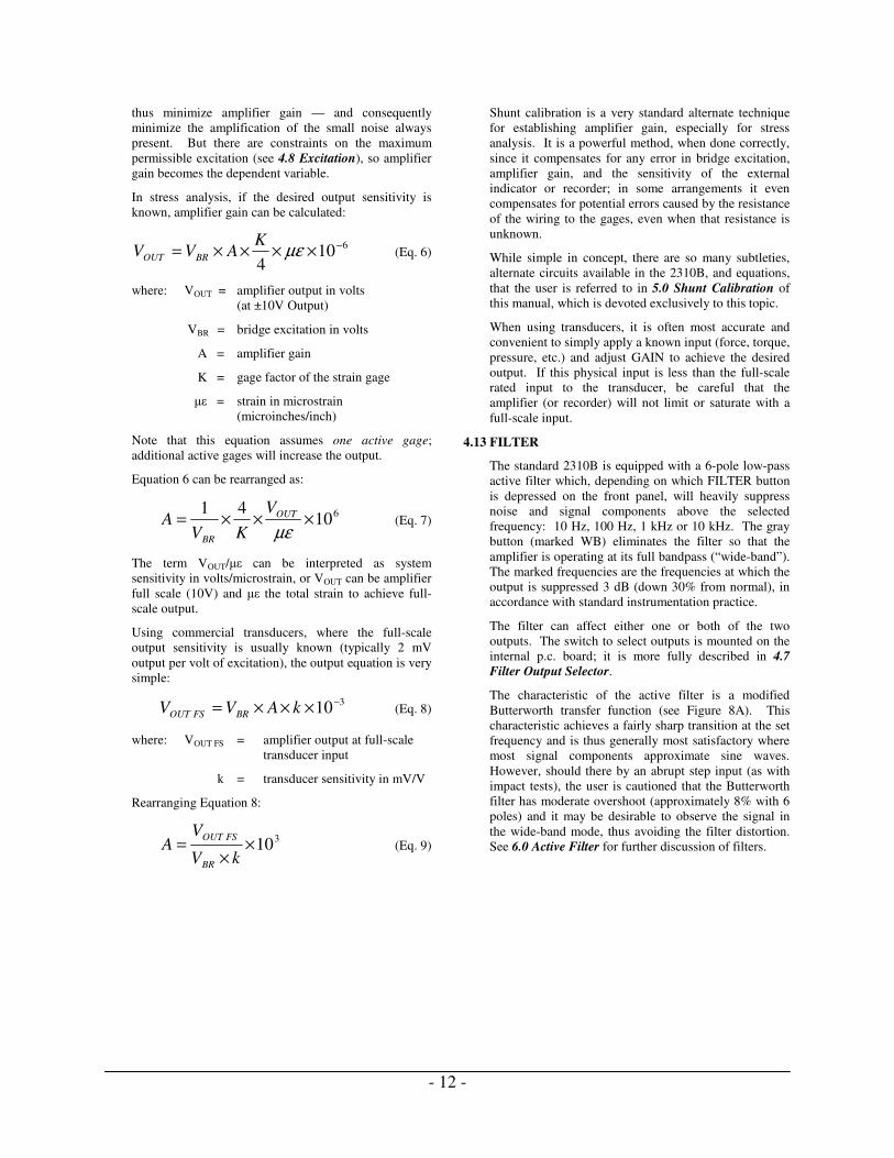
thus minimize amplifier gain — and consequently
minimize the amplification of the small noise always
present. But there are constraints on the maximum
permissible excitation (see 4.8 Excitation), so amplifier
gain becomes the dependent variable.
In stress analysis, if the desired output sensitivity is
known, amplifier gain can be calculated:
6104
−××××= µεK
AVV BROUT (Eq. 6)
where: VOUT = amplifier output in volts
(at ±10V Output)
VBR = bridge excitation in volts
A = amplifier gain
K = gage factor of the strain gage
µε = strain in microstrain
(microinches/inch)
Note that this equation assumes one active gage;
additional active gages will increase the output.
Equation 6 can be rearranged as:
61041
×××=µε
OUT
BR
V
KVA (Eq. 7)
The term VOUT/µε can be interpreted as system
sensitivity in volts/microstrain, or VOUT can be amplifier
full scale (10V) and µε the total strain to achieve full-
scale output.
Using commercial transducers, where the full-scale
output sensitivity is usually known (typically 2 mV
output per volt of excitation), the output equation is very
simple:
310−×××= kAVV BRFSOUT (Eq. 8)
where: VOUT FS = amplifier output at full-scale
transducer input
k = transducer sensitivity in mV/V
Rearranging Equation 8:
310××
=kV
VA
BR
FSOUT (Eq. 9)
Shunt calibration is a very standard alternate technique
for establishing amplifier gain, especially for stress
analysis. It is a powerful method, when done correctly,
since it compensates for any error in bridge excitation,
amplifier gain, and the sensitivity of the external
indicator or recorder; in some arrangements it even
compensates for potential errors caused by the resistance
of the wiring to the gages, even when that resistance is
unknown.
While simple in concept, there are so many subtleties,
alternate circuits available in the 2310B, and equations,
that the user is referred to in 5.0 Shunt Calibration of
this manual, which is devoted exclusively to this topic.
When using transducers, it is often most accurate and
convenient to simply apply a known input (force, torque,
pressure, etc.) and adjust GAIN to achieve the desired
output. If this physical input is less than the full-scale
rated input to the transducer, be careful that the
amplifier (or recorder) will not limit or saturate with a
full-scale input.
4.13 FILTER
The standard 2310B is equipped with a 6-pole low-pass
active filter which, depending on which FILTER button
is depressed on the front panel, will heavily suppress
noise and signal components above the selected
frequency: 10 Hz, 100 Hz, 1 kHz or 10 kHz. The gray
button (marked WB) eliminates the filter so that the
amplifier is operating at its full bandpass (“wide-band”).
The marked frequencies are the frequencies at which the
output is suppressed 3 dB (down 30% from normal), in
accordance with standard instrumentation practice.
The filter can affect either one or both of the two
outputs. The switch to select outputs is mounted on the
internal p.c. board; it is more fully described in 4.7
Filter Output Selector.
The characteristic of the active filter is a modified
Butterworth transfer function (see Figure 8A). This
characteristic achieves a fairly sharp transition at the set
frequency and is thus generally most satisfactory where
most signal components approximate sine waves.
However, should there by an abrupt step input (as with
impact tests), the user is cautioned that the Butterworth
filter has moderate overshoot (approximately 8% with 6
poles) and it may be desirable to observe the signal in
the wide-band mode, thus avoiding the filter distortion.
See 6.0 Active Filter for further discussion of filters.

- 13 -
4.14 DYNAMIC TESTING
Occasionally the only data of interest is the peak-to-peak
amplitude of dynamic signals or the frequency or shape
of the dynamic component, and it may be desirable to
suppress the static component.
To observe purely dynamic signal components, press the
white AC button (below the FILTER buttons). This is
an alternate-action push button: in the “in” position all
signals are ac-coupled (after the preamp); in the “out”
position all signals are dc-coupled. The coupling
constant suppresses 5 Hz signals approximately 5% (the
–3 dB frequency is about 1.7 Hz).
NOTE: The automatic and trim balance controls will
not affect the dc output level in the ac-coupled mode.
The preamplifier remains dc-coupled at all times to
maintain good common-mode rejection. Even when ac
coupling is selected, there is a maximum permissible
differential dc input which must not be exceeded (to
avoid saturation of the preamplifier); this limit is a
function of the GAIN push button selected:
GAIN Button Max DC Diff. Input
X1 ±10 V
X10 ±1 V
X100 or X1000 ±0.1 V
It is recommended that bridge unbalance be held within
5% (25 000 µε @ GF=2) when possible; the Automatic
Bridge Balance circuit is still operable and will
compensate entirely for this much unbalance. (With the
EXCITATION toggle switch ON, simply press AUTO
BAL to RESET momentarily.) Should the bridge
unbalance exceed 5%, AUTO BAL must be OFF (all the
way up) and the selection of GAIN button and
EXCITATION must be made very carefully so as not to
exceed the limits tabulated above.
4.15 TAPE PLAYBACK
The 2310B Amplifier can be used to re-examine data
previously recorded on magnetic tape. A suggested
practice is to originally record the data with no filter on
the TAPE output (TAPE FILTER selector toggle on the
p.c. board set at OUT); the recorded tape thus contains
all possible frequency components from the test. Even
if the data were simultaneously observed and/or
recorded on an oscillograph, with or without filtering,
the tape-recorded data would still be wide-band.
At some later date the tape-recorded data can be played
back through the 2310B and re-examined (using a scope
or recording oscillograph); since the active filter in the
2310B is operable in this playback mode, any filter
frequency (or WB) may be selected. Note that both
outputs are available.
To use the playback mode, move the PLAYBACK
switch on the rear panel of the 2310B to ON (up).
Connect the output from the tape recorder to the INPUT
BNC connector near the top of the rear panel (full-scale
input is ±1.414V or 1 Vrms for a sine wave). Outputs
(±10V and TAPE) appear at their normal connectors.
The only controls on the front panel that are operable in
the playback mode are FILTER buttons (10 to 10K and
WB).
After using the playback mode, do not forget to return
the PLAYBACK switch to NORM! Otherwise, the
normal signal presented to the INPUT connector will
have no effect on the Outputs.
Figure 5: Remote-Operation Wiring

- 14 -
4.16 REMOTE-OPERATION RELAYS (Option Y)
Six isolated relays can be provided to operate the
following functions in the 2310B. See Figure 8.
Shunt CALibration (+A, -A, +B, and –B)
Auto Balance RESET
Bridge EXCITation on/off (to check amplifier
balance)
While the relays are not installed unless Option Y is
specified at time of order, they can be easily installed
later by a qualified technician; all wiring already exists
in the 2310B Amplifier. Each relay requires 5 Vdc (10
mA each, except 25 mA for the bridge excitation relay).
For after-sale installation, order one Relay Kit 120-
001191 for each 2310B Amplifier.
To control the relays in a single 2310B Amplifier the
internal +15V supply may be used, as shown in Figure
8A. When more than one 2310B is to be operated with a
single set of switches (or external relays), an external 5
Vdc power supply is required (250 mA for each 10
channels). Option Y must also be specified for the 2350
Rack Adapter or 2360 Portable Enclosure. (For after-
sale installation, order one Cal Kit 120-001192 for each
2350 Rack Adapter, or Cal Kit 120-001193 for the 2360
Portable Enclosure.) The system would then be wired as
in Figure 5B.
In order to remotely initiate an automatic bridge balance,
the RESET line must first be active for a minimum of 50
milliseconds and then released. (The balance process
starts after the voltage is released.) To remotely turn off
the bridge excitation, the EXCITation off line must be
made active (5 Vdc). The other functions (CALibration)
are turned on when 5 Vdc is supplied to the appropriate
pin and turned off when the voltage is removed.
4.17 QUARTER-BRIDGE NONLINEARITY
The output of a Wheatstone bridge is somewhat
nonlinear with only one active arm. This nonlinearity is
usually insignificant in stress analysis (percent error
equals percent strain @ GF=2). Should high strains be
encountered (post-yield studies or tests on some non-
metallics), the error can be removed during data
reduction, although the user is cautioned regarding
uncertainty of the value of gage factor above 1% strain.
If it is desired to obtain an output which is linear with
∆R in one arm of a bridge, this can be achieved with the
2310B.
This technique utilizes the remote-sense leads to
maintain constant voltage across a dummy resistor, and
therefore constant current through this resistor and
through the active arm. Connections to the INPUT plug
are as follows:
Two changes to the operating procedure are required:
a) The Remote SENSE switch on the p.c. board must
be at REMOTE, and
b) The EXCITATION selector switch must be set at
half the desired bridge excitation.
The user may notice that bridge balance is somewhat
affected by this circuit (e.g., 0.5% with a 500Ω half
bridge), but this is well within the range of the
Automatic Bridge Balance circuit. (The source of this
shift is the presence of R34 — 100 kΩ — across the
active resistance.)
5.1 INTRODUCTION
Shunt calibration is a very powerful technique to
determine total system “gain” in Wheatstone bridge
systems such as the 2310B. In general, one arm of the
input bridge is shunted with a specific resistance, which
introduces a specific -∆R into this arm (simulating a
compressive strain in a strain gage). The amplifier
output will respond exactly as if that specific -∆R (i.e.,
stain) actually had occurred with the existing bridge
excitation and amplifier gain. It is only necessary to
calculate the simulated strain and read the amplifier
output to determine the system sensitivity.
IMPORTANT: It should be emphasized that the intent
of shunt calibration is to determine the performance of
the circuit and instrument into which the gage is wired;
in no way does it verify the ability of the gage itself to
measure strain nor the characteristics of its performance.
While the basic shunt calibration concept and equations
are simple and well-known, the presence of leadwire
resistance can have very significant effects on the
accuracy of the technique. Either the precise shunt
circuit used must be chosen such that the leadwire
resistance has no net effect, or a correction must be
made for this effect.
5.0 SHUNT CALIBRATION
Figure 6: Connections to Input Plug

- 15 -
The shunt calibration circuits available in the 2310B are
designed to be exceptionally versatile and easy to
change. Most circuits apply specifically to stress
analysis application; when using commercial strain gage
transducers the double-shunt method is suggested (5.4
Transducers).
5.2 SHUNT CALIBRATION COMPONENTS IN 2310B
The two CAL switches on the front panel normally
provide two independent values (A and B) of simulated
strain, each of which can be either + or -. (If both
switches are operated simultaneously the values are
algebraically additive.)
With Option Y additional relays are installed in the
2310B such that any of these four switch positions can
be operated remotely [4.16 Remote Operation Relay
(Option Y)].
Four calibration resistors, two associated with the “A”
switch and two with the “B” switch, are installed in the
miniature sockets on the right side of the p.c. board (see
Figure 4). These resistors may be changed in the field to
suit specific test requirements. See 5.5 Standard
Calibration Resistors.
A blue ten-switch Calibration Circuit Selector is
installed on the right side of the p.c. board (see Figure
4). Only two or three (or four for transducers) should
ever be closed (up) for any given circuit.
Note that the switches are divided into four groups, as
marked at the bottom: P+, P-, S+, and S-, corresponding
to the four corners of the bridge. Each group has an
“INT” switch, which connects the calibration circuit to
the indicated corner of the bridge internal to the 2310B;
and an “R” switch, which connects the circuit to a
dedicated pin in the INPUT connector — to be used
when shunting a remote active gage. The S- group has
two additional switches for shunting the internal dummy
gages (D120 and D350).
5.3 SHUNT CALIBRATION — STRESS ANALYSIS
Shunt calibration can be achieved by shunting any one
of the four arms of the input bridge — this includes the
active gage and the bridge completion arms in the
2310B. The same equation applies, but note the
definition of Ra:
610)('
×+
=acal
a
calRRK
Rµε (Eq. 10)
where: µεcal = strain simulated (microstrain)
Ra = resistance of leg shunted (ohms)
K´ = effective gage factor of active gage
Rcal = resistance of calibration resistor
(ohms)
Ra may not be equal to the resistance of the active gage
when the shunt is across one arm of the dummy half
bridge. (But also note that no correction factor is ever
necessary for the shunting effect of the resistance
balance circuit, since the 2310B does not use the shunt
method for bridge balance.)
Gage factor (K´) in equation 10 may be the actual
package gage factor of the active strain gage (corrected
for temperature, when necessary), or it may be a value
adjusted for leadwire desensitization:
lg
g
RR
RKK
+×=' (Eq. 11)
where: K = gage factor of active gage
Rg = resistance of active gage (ohms)
Rl = resistance of leadwire(s) in series
with active gage (usually the
resistance of one leadwire) (ohms)
The specific gage factor correction applicable to the
various circuits is indicated in Chart 1.
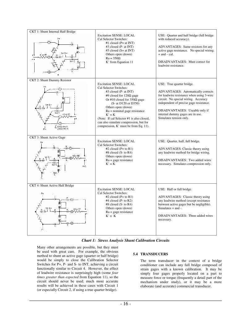
Chart 1 tabulates the recommended shunt calibration
circuits available in the 2310B, together with the switch
settings and wiring necessary to achieve them.
The calibration resistor value (calculated from Equation
10) would apply to CAL Switch A if the resistor is
installed at position A1 or A2, or it would apply to CAL
Switch B if installed at position B1 or B2; CAL A and
CAL B are totally independent. Provided that the
Calibration Selector Switches are set as specified in the
chart, resistors installed at positions not called for have
no effect on the output; it is not necessary to remove
them.
- 16 -
CKT 1: Shunt Internal Half Bridge
Excitation SENSE: LOCAL
Cal Selector Switches:
#1 closed (P+ at INT)
#3 closed (P- at INT)
#5 closed (S+ at INT)
Others open (down)
Ra = 350Ω
K’ from Equation 11
USE: Quarter and half bridge (full bridge
with reduced accuracy).
ADVANTAGES: Same resistors for any
active gage resistance. No special wiring.
+ and – cal.
DISADVANTAGES: Must correct for
leadwire resistance.
CKT 2: Shunt Dummy Resistor
Excitation SENSE: LOCAL
Cal Selector Switches:
#3 closed (P- at INT)
#9 closed for 120Ω gage
Or #10 closed for 350Ω gage
(S- at D120 or D350)
Others open (down)
Ra = nominal gage resistance
K’ = K
(Note: If cal Selector #1 is also closed,
can also simulate compression, but for
compression, K’ must be from Eq. 11).
USE: True quarter bridge.
ADVANTAGES: Automatically corrects
for leadwire resistance when using 3-wire
circuit. No special wiring. Accuracy
independent of precise gage resistance.
DISADVANTAGES: Useable only if
internal dummy gages are in use.
Simulates tension only.
CKT 3: Shunt Active Gage
Excitation SENSE: LOCAL
Cal Selector Switches:
#2 closed (P+ to R1)
#8 closed (S- to R4)
Others open (down)
Ra = gage resistance
K’ = K
USE: Quarter, half, full bridge.
ADVANTAGES: Classic theory using
any leadwire method for bridge wiring.
DISADVANTAGES: Two added wires
necessary. Simulates compression only.
CKT 4: Shunt Active Half Bridge
Excitation SENSE: LOCAL
Cal Selector Switches:
#2 closed (P+ to R1)
#4 closed (P- to R2)
#8 closed (S- to R4)
Others open (down)
Ra = gage resistance
K’ ≅ K
USE: Half or full bridge.
ADVANTAGES: Classic theory using
any leadwire method (except resistance
between active gages but be negligible).
Simulates + and -.
DISADVANTAGES: Three added wires
necessary.
Chart 1: Stress Analysis Shunt Calibration Circuits
Many other arrangements are possible, but they must
be used with great care. For example, the obvious
method to shunt an active gage (quarter or half bridge)
would be simply to close the Calibration Selector
Switches for P+, P- and S- to INT, achieving a circuit
functionally similar to Circuit 4. However, the effect
of leadwire resistance is surprisingly high (some four
times greater than expected from Equation 11), so the
circuit should never be used; much more accurate
results will be achieved in these cases with Circuit 1
(or especially Circuit 2, if using a true quarter bridge).
5.4 TRANSDUCERS
The term transducer in the context of a bridge
conditioner can include any full bridge composed of
strain gages with a known calibration. It may be
simply four gages properly located on a part to
measure force or torque (frequently a detail part of the
mechanism under study), or it may be a more
elaborate (and accurate) commercial transducer.

- 17 -
Commercial transducers are much more complex
circuits since they typically have a number of
additional resistive elements to correct for the effects
of temperature to achieve the desired precise span
calibration. Nonetheless, this complexity can usually
be overlooked without greatly compromising the
accuracy of shunt calibration, if done properly.
Shunt Calibration per Calibration Certificate: Many transducer manufacturers provide shunt
calibration information as part of the calibration
certificate. When available, this is the most reliable
method of calibration, but the specified resistance
must be connected precisely as indicated by the
manufacturer. Sometimes there are two separate pins
dedicated to shunt calibration; additional leads are
required to accomplish calibration with resistors
installed inside the 2310B. In other cases the pins
may be one normal input lead and one normal output
lead. Since the effects of leadwire resistance are very
measurable, additional leads dedicated to the shunt
calibration circuit must be used between the
transducer connector and the INPUT connector to the
2310B.
The complete schematic of the available connections
for shunt calibration of transducers is shown in Figure
7.
As an example of transducer shunt calibration, assume
that the certificate for the transducer specifies that a 10
kΩ resistor should be placed between the positive
excitation (P+) pin and the negative output (S-) pin. A
suggested method with the 2310B would be:
a) Install a 10 kΩ resistor in position “A2” on the
p.c. board.
b) In addition to the normal 4-wire connection to the
transducer (6-wire if remote excitation sense is
used), connect two additional wires; one from the
positive excitation pin on the transducer to pin M
of the 2310B INPUT plug, the other from the
transducer negative output pin to pin N of the
2310B INPUT plug.
c) Inside the 2310B, Calibration Selector Switches 2
and 8 should be ON (all others open, or down).
Figure 7: Transducer Shunt-Cal Circuitry

- 18 -
Excitation SENSE would be at LOCAL, unless
the basic 6-wire system is in use, in which case it
would be at REMOTE.
d) To insert the 10 kΩ shunt, move the CAL A
toggle (on the front panel) to “-“.
If shunt calibration data is not known, the best
procedure is to calculate values to be used in double-
shunt calibration; this procedure corrects for any
normal nonsymmetry in the transducer by
simultaneously shunting two opposite legs of the
bridge. To calculate the resistor value, use the
following equation:
)5.0500
(0 −=−k
RR shuntdouble (Eq.12)
where: Rdouble-shunt = value of each shunt
resistor (ohms)
R0 = output resistance of
transducer (usually 350
ohms)
K = output to be simulated
(mV/V)
Common values would be as follows for a 350Ω
transducer:
MV/V Ohms (double-shunt)
3 58,158
2 87,325
1.5 116,492
1 174,825
The above resistors must be placed electrically at the
transducer connector (rather than the 2310B INPUT
plug) to eliminate the sizable effect of leadwire
resistance. To achieve this, four “remote-calibration”
pins (E, M, N and R) are provided in the input plug, as
shown in Figure 7.
The resistors (value as calculated in Equation 12)
would be soldered to the p.c. board turrets in positions
A1 and A2 (or B1 and B2). Now the selected
transducer output, either + or -, can be simulated
simply by operating the CAL A (or CAL B) front
panel switch.
A common arrangement may be to calculate two
resistor values (representing perhaps 100% transducer
output and 25% output), putting one pair at A1 and
A2, the other pair at B1 and B2; now either 100% or
25% of full output can be simulated by using either
CAL A or CAL B.
It is important to emphasize that when using semi-
conductor (piezoresistive) transducers, EXCITATION
must be set at the manufacturer’s specified voltage to
achieve proper calibration. Transducers using foil
gages may be excited with any voltage below the
maximum value specified by the manufacturer,
although best overall system performance will usually
be achieved with 50% to 75% of the permissible
maximum.
5.5 STANDARD CALIBRATION RESISTORS
The 2310B is intended to be ready for use as received,
with bridge completion resistors, dummy gages and
shunt calibration resistors installed. The standard
shunt calibration resistors have been selected for
maximum flexibility for stress analysis. These
resistors are as follows:
A1 — 874.8k ±0.1%
A2 — 59.94k ±0.1%
B1 — 174.8k ±0.1%
B2 — 174.8k ±0.1%
These values provide the following shunt calibration
levels (for identification of Cal Selector Switches, see
Figure 4):
Input Circuit
Arm
Shunted
Cal
Selector
Switches
On
Strain Simulated
@ GF=2
¼ & ½
bridge, 350Ω
full bridge
Dummy
half
bridge
1, 3, 5 ±A = ±200µε
±B = ±1000µε
120Ω ¼
bridge
Dummy
resistor
3, 9 +A = +1000µε
350Ω ¼
bridge
Dummy
resistor
3, 10 +B = +1000µε
350Ω
transducer
(double-
shunt)
All 1, 3, 5, 7 ±B = ±1 mV/V*
*These values assume zero leadwire resistance.

- 19 -
6.1 FILTER CHARACTERISTICS
a) The standard 2310B is supplied with an active 6-
pole filter with Butterworth characteristics having
high-frequency cut-off at the following
frequencies: 10, 100, 1000 and 10 000 Hz.
This section describes filter characteristics as relates to
the 2310B.
The choice of filter characteristic (Butterworth or
Bessel) is a compromise. With reference to Figure 8,
note the following:
a) The Butterworth filter falls off much more
sharply around the –3dB frequency (FCO in the
curves).
b) While both filters (with equal poles) ultimately
reach the same slope at high frequencies, the
sharpness of the Butterworth filter at FCO results
in better attenuation at any given high frequency.
c) Should there be an instantaneous step input, the
Butterworth filter will produce 5 to 8% overshoot
(assuming precise component values), whereas
the Bessel filter has no overshoot.
Thus the choice of characteristic is very dependent on
the type of testing performed. However, the
Butterworth, with its sharper cut-off, is generally
preferred.
When high noise rejection is required near FCO, a filter
with 6 poles is highly desirable. Although, note from
Figure 8 that there is no discernible improvement
below FCO as the number of poles is increased.
6.0 ACTIVE FILTER
Figure 8: Filter Characteristics

- 20 -
The rise time (10% to 90%) for step inputs is virtually
fixed; it is independent of both filter characteristic and
number of poles:
ondsinF
TimeRiseCO
sec35.0
≅ (Eq.13)
where: FCO is the cut-off frequency (-3dB) in Hz.
All multipole filters introduce a significant time delay
near and above the cut-off frequency. In multi-
channel dynamic studies where instantaneous outputs
from several channels are to be compared or analyzed
at a specific point in time (for example, reduction of a
3-element strain gage rosette), these three channels
must have identical filters to avoid “data skew” caused
by different time delays in the three channels.
Maintenance is to be done only by qualified technicians.
7.1 ADJUSTMENTS
To assist in maintenance, the following the diagram is
provided to indicate the position of the IC and adjustments
that are used to calibrate the 2310B. Also shown are the
relays used for shunt cal and zero functions. Schematic
diagrams are available to those who wish to gain a more
detailed understanding of circuit operations and for
organizations that choose to do their own repairs and
adjustments. Our Applications Engineering Department
can provide these diagrams, upon request, in paper and/or
electronic formats.
7.0 MAINTENANCE
Figure 9: P.C. Board Layout — Trim Adjustments

- 21 -
There are a number of trim adjustments on the p.c.
board; no adjustment of these controls should be
necessary unless a component is changed, principally
one of the integrated circuits. Each trim control is
marked on the p.c. board with a letter of the alphabet
to assist the technician. Additionally, many test points
are marked on the component side of the board.
Figure 9 shows the location of the various
adjustments.
The 2310B must have ac power during servicing (see
4.1 Setup and AC Power); accessory power cord 120-
001196 is suggested.
The trim adjustments fall into three general categories:
power supply checks and set points, common-mode
adjustment, and balance adjustments for most
operational amplifiers.
The bridge power supply reference can be set with or
without an input to the 2310B, using a digital
voltmeter. It is should be set 0.1% (if possible) after
15 minutes warmup.
METER LEADS READING ADJUST
- +
TP16* TP 5 +15.00V±0.5V NA
TP16* TP 17 -15.00V±0.5V NA
P- TP18 +18.00V±0.5V NA
P- TP19 +15.00V±0.01V C
*TP16 is the same as chassis or common.
The amplifier balance controls should be set in the
sequence listed at right, after the instrument has been
warmed up for at least 15 minutes. The inputs must be
shorted together and grounded by connecting INPUT
plug pins A, J and P together. All readings should be
made with a digital voltmeter or stable dc scope with a
resolution of at least 1 mV; when possible set balances
to within 0.2 mV of zero. All readings are relative to
circuit common (OUTPUT pin 1). The front panel
AMP BAL trimmer must be approximately centered
(11 turns from one end), EXCITATION at OFF, and
AC coupling button “out” (for dc coupling). Also, the
front panel settings listed at right must be made prior
to adjustment and not changed unless subsequently
directed to do so.
Auto Balance adjustments should be made with a
350Ω bridge connected to the input; it should be
possible to unbalance this bridge randomly up to about
3% unbalance.
METER
LEAD FRONT PANEL
ADJUST
MENT
IC
BALANCED
TP1 GAIN button X100 G
U16, U18,
U21
TP1 GAIN button X1 J U19
TP1 GAIN button X1000 G
U16, U18,
U21
TP2 — N U20
TP2 AC button “IN” * U20
TP3 GAIN button X1 and
dial 11.000
R U17
TP4 GAIN dial 11.000
FILTER 100
T U12, U13,
U14
TP6 FILTER WB V U25
TP7 — W U8
TP8 — X U26
*Press AC button IN, reading shift <5mV
Adjustments D and E are set to make the 2310B
output (after “balancing” the bridge) independent of
bridge excitation:
a) Set GAIN at approximately X100; bridge outputs
(amplifier inputs) shorted together.
b) With EXCITATION at OFF, null LED’s with
AMP BAL.
c) EXCITATION ON, set at 15 V. Press RESET;
use TRIM to extinguish LED’s.
d) EXCITATION at 2 V; LED’s should stay out. If
+ LED lights, turn adjustment E clockwise to
slightly light – LED, and vise versa.
e) If an adjustment was required, repeat (c) and (d).
f) Unbalance the input bridge approximately 3%
(10K shunt across one 350Ω arm suggested) and
remove short across bridge output.
g) Follow steps (b) through (e), but trim adjustment
D.
Adjustment F is set for best null (on average) using
Auto Balance. The following procedure is suggested:
a) Set GAIN at 500 and EXCITATION at 5 V.
b) With EXCITATION at OFF, null LED’s with
AMP BAL.
c) With any random bridge unbalance, turn
EXCITATION to ON and press RESET. If, at
“balance”, the + LED is lit somewhat, turn
adjustment F counter-clockwise (and vice versa)
until both LED’s are extinguished at “balance”.

- 22 -
d) Repeat above procedure with several random
bridge unbalances to achieve best average
performance. (If reading the ±10V output with a
DVM, readings at “balance” ideally should be
between 0 and –3 mV, which is the theoretical
resolution of the circuit at these settings.)
Adjustments H, L, M and Y (C31) all affect common-
mode rejection in the preamplifier. They are most
conveniently set using an audio oscillator (10 Hz to 5
kHz):
a) Connect the oscillator between circuit ground and
the two amplifier inputs (INPUT pins A and J)
shorted together. Set the oscillator for about 10
Vp-p (3.5 Vrms).
b) Connect oscilloscope to ±10V (TP7) output, ac-
coupled.
c) Set GAIN dial at 1.000 and press X1 button.
d) Set oscillator at 10 Hz; adjust M for best null on
scope.
e) Set oscillator at 1 kHz; adjust L for best null.
f) Repeat (d) and (e) if adjustments were required.
g) Press X100 GAIN button.
h) Set oscillator at 10 Hz; adjust H for best null.
i) Set oscillator at 1 kHz; adjust capacitor Y (C31)
for best null.
j) Repeat (h) and (i) if adjustments were required.
k) If (h) and (i) required significant adjustment,
repeat from (c) on.
7.2 BATTERY REPLACEMENT
The current drain from the keep-alive batteries in the
automatic bridge balance circuit is continuous with
POWER off, whether the instrument is plugged in or
not, but this current is so small 5 to 10 nA) that self-
discharge (i.e., shelf-life) is far more significant.
The batteries should be replaced when the test circuit
indicates low voltage (see 4.11 Battery Test), or
routinely two years after installation.
The batteries used in the 2310B are widely used and
are available at most electronic supply stores. Eagle
Picher PT-2150 (Lithium 3.6Volt, 1/2AA) or equal is
recommended for a replacement. Any of the
following silver oxide batteries may be used (two
required):
To replace the battery:
a) Disconnect power and remove cover on left side
of the 2310B.
b) Locate the battery holder near the rear of the
2310B.
c) Note the orientation of the existing battery.
d) Remove and properly dispose of the old battery
in accordance with local codes.
e) Install the new battery with the positive end (case
of cell) toward the rear of the instrument, and the
negative end toward the front.
f) Replace 2310B side cover.
g) Apply ac power to the 2310B and press BAT
TEST; the + OUTPUT lamp should light.
7.3 COMPONENT REPLACEMENT
It is recommended that a defective 2310B be returned
to Vishay Micro-Measurements for factory service,
especially during the warranty period (to preserve the
warranty); however, a qualified technician can often
repair the unit in the field. Most electronic
components used are standard commercially available
items. Any component can be purchased from Vishay
Micro-Measurements (if the Vishay Micro-
Measurements part number is not listed below, please
provide us with the component symbol and value —
or an adequate description of the part — and the
instrument serial number).
The following information may be of value for field
service.
7.3a Resistors:
The 1% resistors are generally 100 ppm/°C, and
0.1% values are generally 25 ppm/°C).
All 0.05% and tighter tolerances are Vishay
SMR1DR (2 ppm/°C) and must be ordered from
Vishay Micro-Measurements.
Resistors R71 through R74 are part of the bridge
completion assembly and must be ordered as part
200-131240.
7.3b Connectors Symbol P/N
Input plug, 15-pin
[Bendix PT06A-14-15P(SR)] P5 12X300531
Mating power plug (not supplied)
(ITT/Cannon DA15S or equal) — 12X300151
Remote cal plug (for 2350/2360)
(Cinch-Jones S-308-CCT) — 12X300533
Line cord (for 2350 and 2360)
(Belden 17742) — 21X300126
7.3c Battery
Keep-alive supply
(Eagle Picher PT-2150) B1
23X500004
(1 required)
7.3d Toggle Switches
Filter selector (on p.c.b.)
(Grayhill 76TC03) SW1 10X900046
Excitation sense selector
(on p.c.b.) (Grayhill 76TD01) SW5 10X900047
- 23 -
Calibration selector (on p.c.b.)
(CTS 206-10) SW7 10X900048
Cal A and Cal B
(C&K 7103P3D9V30QE)
S8,
S9 10X600136
Auto Balance
(C&K 7213PD9V38) S10 10X600160
Excitation on/off
(C&K 7201P3D9V30QE) S12 10X600137
7.3e Relays
Calibration
(CP Clare PRMA2A05)
K1, K2,
K3, K4 11X500085
Remote cal & reset
(CP Clare PRMA1A05)
K5, K7,
K8, K9,
K10
11X500078
Remote excitation on/off
(Hamlin HE 721C0500) K6 11X500077
7.4 FUSE REPLACEMENT
Fuse replacement is to be done only by qualified
technicians with all cabling disconnected including the
power cord. All fuses are rated at 250V and are
appropriate for both 115V and 230V operation.
Substituting non-recommended fuse values may create
hazardous conditions.
Model 2310B & 2331: Two axial-lead internal
power fuses are recommended as follows:
0.25A fast acting, Littelfuse #251.250 (UL/CSA).
(Vishay M-M #18X300007)
Model 2350/2360: A power fuse is located on the
rear panel. The following lists the recommended time
lag fuse ratings:
2350: UL/CSA: T 1 A IEC: T .8 A
2360: UL/CSA: T .5 A IEC: T .4 A
APPENDIX – 1000-OHM BRIDGE COMPLETION
The 2310B Signal Conditioning Amplifiers provides the capability of 1000-ohm quarter bridge operation. For this mode, the
120-ohm dummy terminal (pin B of input plug) is converted to a 1000-ohm dummy terminal by removing a solder shunt from a
factory-installed precision resistor in series with the internal 120-ohm dummy gage. To make this conversion the user must de-
solder a solder pad located on the circuit side of the small connector PC board that is attached to the INPUT connector. The 880-
ohm resistor, R1 is located on the connector-side of the board. The solder pad is located on the top-right side of the board and is
shown below:
OHM
Figure 10: Location of Solder Pad for 1000-Ohm Dummy

- 24 -
WARRANTY
Vishay Micro-Measurements warrants all instruments it manufactures to be free from defect in materials and factory
workmanship, and agrees to repair or replace any instrument that fails to perform as specified within three years after date of
shipment. Coverage of computers, cameras, rechargeable batteries, and similar items, sold in conjunction with equipment
manufactured by Vishay Micro-Measurements and bearing the identifying name of another company, is limited under this
warranty to one year after the date of shipment. The warranty on non-rechargeable batteries and similar consumable items is
limited to the delivery of goods free from defects in materials and factory workmanship. This warranty shall not apply to any
instrument that has been:
i. repaired, worked on or altered by persons unauthorized by Vishay Micro-Measurements in such a manner as to injure, in
our sole judgment, the performance, stability, or reliability of the instrument;
ii. subject to misuse, negligence, or accident;
or
iii. connected, installed, adjusted, or used otherwise than in accordance with the instructions furnished by us.
At no charge, we will repair, at our plant, or an authorized repair station, or at our option, replace any of our products found to be
defective under this warranty.
This warranty is in lieu of any other warranties, expressed or implied, including any implied warranties of
merchantability or fitness for a particular purpose. There are no warranties, which extend beyond the description on the
face hereof. Purchaser acknowledges that all goods purchased from Vishay Micro-Measurements are purchased as is, and
buyer states that no salesman, agent, employee or other person has made any such representations or warranties or
otherwise assumed for Vishay Micro-Measurements any liability in connection with the sale of any goods to the
purchaser. Buyer hereby waives all rights buyer may have arising out of any breach of contract or breach of warranty on
the part of Vishay Micro-Measurements, to any incidental or consequential damages, including but not limited to
damages to property, damages for injury to the person, damages for loss of use, loss of time, loss of profits or income, or
loss resulting from personal injury.
Some states do not allow the exclusion or limitation of incidental or consequential damages for consumer products, so the above
limitations or exclusions may not apply to you.
The purchaser agrees that the Purchaser is responsible for notifying any subsequent buyer of goods manufactured by Vishay
Micro-Measurements of the warranty provisions, limitations, exclusions and disclaimers stated herein, prior to the time any such
goods are purchased by such buyer, and the Purchaser hereby agrees to indemnify and hold Vishay Micro-Measurements
harmless from any claim asserted against or liability imposed on Vishay Micro-Measurements occasioned by the failure of the
Purchaser to so notify such buyer. This provision is not intended to afford subsequent purchasers any warranties or rights not
expressly granted to such subsequent purchasers under the law.
Vishay Micro-Measurements reserves the right to make any changes in the design or construction of its instruments at any time,
without incurring any obligation to make any change whatever in units previously delivered.
Vishay Micro-Measurements’ sole liabilities, and buyer’s sole remedies, under this agreement shall be limited to the purchase
price, or at our sole discretion, to the repair or replacement of any instrument that proves, upon examination, to be defective,
when returned to our factory, transportation prepaid by the buyer, within the applicable period of time from the date of original
shipment.
Return transportation charges of repaired or replacement instruments under warranty will be prepaid by Vishay Micro-
Measurements.
Vishay Micro-Measurements is solely a manufacturer and assumes no responsibility of any form for the accuracy or adequacy of
any test results, data, or conclusions, which may result from the use of its equipment.
The manner in which the equipment is employed and the uses to which the data and test results may be put are completely in the
hands of the Purchaser. Vishay Micro-Measurements shall in no way be liable for damages consequential or incidental to defects
in any of its products.
This warranty constitutes the full understanding between the manufacturer and buyer, and no terms, conditions, understanding, or
agreement purporting to modify or vary the terms hereof shall be binding unless hereafter made in writing and signed by an
authorized official of Vishay Micro-Measurements.