Embed Size (px)
Citation preview

Technical Report Documentation Page 1. Report No.
FHWA/TX-01/1439-6
2. Government Accession No.
3. Recipient's Catalog No.
5. Report Date
September 2000
4. Title and Subtitle
SIGNAL DESIGN MANUAL FOR DIAMOND INTERCHANGES 6. Performing Organization Code
7. Author(s)
Srinivasa R. Sunkari and Thomas Urbanik II, P.E.
8. Performing Organization Report No.
Report 1439-6 10. Work Unit No. (TRAIS)
9. Performing Organization Name and Address
Texas Transportation Institute The Texas A&M University System College Station, Texas 77843-3135
11. Contract or Grant No.
Project No. 0-1439 13. Type of Report and Period Covered
Manual: September 1999-August 2000
12. Sponsoring Agency Name and Address
Texas Department of Transportation Construction Division Research and Technology Transfer Section P. O. Box 5080 Austin Texas 78763-5080
14. Sponsoring Agency Code
15. Supplementary Notes
Research performed in cooperation with the Texas Department of Transportation and the U.S. Department of Transportation, Federal Highway Administration. Research Project Title: TxDOT Support of the Texas A&M IVHS Research Center of Excellence 16. Abstract
A comprehensive signal design of a diamond interchange is essential for its efficient operation. The design process should consider the likely operational scenarios that the operations engineer will face in the future. The signal design should also consider the requirements of the maintenance technicians at the interchange. This design manual provides guidelines for the signal design of a diamond interchange. The manual will provide guidelines on the number controllers required, lane assignment and other geometric considerations, detector requirements, and other general considerations. General signal design guidelines should follow the “Traffic Signals Manual - Traffic Operations Division December 1999” and the Texas Manual on Uniform Traffic Control Devices (MUTCD). 17. Key Words
Diamond Interchange, Design Guidelines, Phasing, Detector Configuration, Traffic Signals Manual
18. Distribution Statement
No restrictions. This document is available to the public through NTIS: National Technical Information Service 5285 Port Royal Road Springfield, Virginia 22161
19. Security Classif.(of this report)
Unclassified
20. Security Classif.(of this page)
Unclassified
21. No. of Pages
26
22. Price
Form DOT F 1700.7 (8-72) Reproduction of completed page authorized


SIGNAL DESIGN MANUAL FOR DIAMOND INTERCHANGES
by
Srinivasa R. Sunkari Assistant Research Scientist
Texas Transportation Institute
and
Thomas Urbanik II, P.E. Associate Director
Texas Transportation Institute
Project Report No. 1439-6 Project No. 0-1439
Research Project Title: TxDOT Support of the Texas A&M IVHS Research Center of Excellence
Sponsored by the Texas Department of Transportation
In Cooperation with the Federal Highway Administration,
U.S. Department of Transportation.
September 2000
TEXAS TRANSPORTATION INSTITUTE The Texas A&M University System College Station, Texas 77843-3135


v
DISCLAIMER The contents of this report reflect the views of the authors, who are responsible for the opinions, findings, and conclusions presented herein. The contents do not necessarily reflect the official views or policies of the Federal Highway Administration, US Department of Transportation, or the Texas Department of Transportation. This report does not constitute a standard, specification, or regulation. The engineer in charge of this project was Thomas Urbanik II, PE # 42384 (Texas).


vii
TABLE OF CONTENTS
List of Figures........................................................................................................................................viii List of Tables ........................................................................................................................................... ix Introduction............................................................................................................................................... 1 Lane Geometry.......................................................................................................................................... 1
U-turn Lanes ......................................................................................................................................... 2 Frontage Road Approach ...................................................................................................................... 3 Arterial (External) Approach ................................................................................................................ 3 Interior Approach.................................................................................................................................. 4
Phase Numbering...................................................................................................................................... 4 Signal Hardware........................................................................................................................................ 5
Number of Controllers .......................................................................................................................... 5 Placement of Controller Cabinet........................................................................................................... 5 Signal Heads ......................................................................................................................................... 5 Pedestrian Push Buttons and Signal Heads........................................................................................... 9
Loop Detectors.......................................................................................................................................... 9 Additional Detector Design Considerations........................................................................................ 15
Cabinets, Conduits, and Cables .............................................................................................................. 15

viii
LIST OF FIGURES
Figure 1. Typical Intersection for Diamond Interchange............................................................................. 1 Figure 2. Critical Lane Volumes.................................................................................................................. 2 Figure 3. Lane Arrangement on an External Arterial Approach.................................................................. 3 Figure 4. Recommended Phase Designation at a Diamond Interchange ..................................................... 4 Figure 5. Signal Head Indications................................................................................................................ 6 Figure 6. Signal Head Configurations for Various Approaches .................................................................. 7 Figure 7. Signal Head Placement and Configuration at a Diamond Interchange ........................................ 8 Figure 8. Pedestrian Movements at a Diamond Interchange ....................................................................... 9 Figure 9. Detector Placement on Arterial Approach.................................................................................. 10 Figure 10. Detector Placement on the Interior Approach .......................................................................... 10 Figure 11. Detector Placement on Frontage Road Approach .................................................................... 11 Figure 12. Typical Diamond Interchange Detector Layout for Three-Phase Operation............................ 13 Figure 13. Typical Diamond Interchange Layout for Four-Phase Operation ............................................ 14 Figure 14. Conduit and Pull Box Details ................................................................................................... 16

ix
LIST OF TABLES
Table 1. Detector Configuration on Various Approaches.......................................................................... 12 Table 2. Distance of Detectors Based on Approach Speed........................................................................13 Table 3. Loop Setback Distances for Three-Phase Diamond Operation.................................................... 14

1
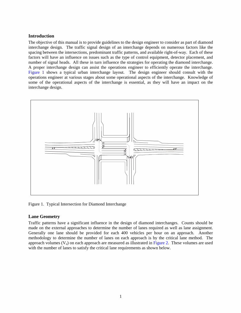
Introduction The objective of this manual is to provide guidelines to the design engineer to consider as part of diamond interchange design. The traffic signal design of an interchange depends on numerous factors like the spacing between the intersections, predominant traffic patterns, and available right-of-way. Each of these factors will have an influence on issues such as the type of control equipment, detector placement, and number of signal heads. All these in turn influence the strategies for operating the diamond interchange. A proper interchange design can assist the operations engineer to efficiently operate the interchange. Figure 1 shows a typical urban interchange layout. The design engineer should consult with the operations engineer at various stages about some operational aspects of the interchange. Knowledge of some of the operational aspects of the interchange is essential, as they will have an impact on the interchange design.
Figure 1. Typical Intersection for Diamond Interchange
Lane Geometry Traffic patterns have a significant influence in the design of diamond interchanges. Counts should be made on the external approaches to determine the number of lanes required as well as lane assignment. Generally one lane should be provided for each 400 vehicles per hour on an approach. Another methodology to determine the number of lanes on each approach is by the critical lane method. The approach volumes (Vn) on each approach are measured as illustrated in Figure 2. These volumes are used with the number of lanes to satisfy the critical lane requirements as shown below.

2
Fro
ntag
eR
oad
Arterial
Arterial
Fro
ntag
eR
oad
V1
V2
V3
V4
Figure 2. Critical Lane Volumes
Design engineers can evaluate the number of lanes required at a diamond interchange using the approach volumes as shown below.
V1/L1 + V2/L2 + V3/L3 + V4/L4 # 1500 vehicles per hour
Where:
V1 to V4 = Approach volumes in vehicles per hour
L1 to L4 = Number of lanes on each approach Such an approach is required for designing a new interchange. For designing an existing interchange, additional and detailed turning movement counts can help in more detailed lane assignment. These turning movement counts can be input into the PASSER III program. The PASSER III program is used to optimize diamond interchanges and to analyze alternative designs.
U-turn Lanes U-turn lanes will significantly improve traffic operation. They are essential for closely spaced interchanges, and engineers should provide them for all interchanges with one-way frontage roads.

3
Frontage Road Approach The lane assignment on the frontage road should reflect the proportion of turning and through movements. The number of lanes from which vehicles can turn left is limited by the number of through lanes available in the interior of the interchange. This limitation can be a constraint in the operation of the interchange when high left-turning volumes from the frontage roads as well as high through volumes from the external arterial approach exist. Right-turn bays should be designed on frontage road approaches if right-of-way (ROW) permits. The lengths of the right-turn bays should be such that they extend beyond the upstream detectors placed on the approaches. This placement allows for the right-turning traffic to move into the right-turn bay without activating the detectors. Detailed drawings for this configuration are illustrated in Figure 11 of this document on Page 11.
Arterial (External) Approach Ideally the arterial approach should have right-turn bays. These bays should be of sufficient length to extend beyond the upstream detectors in the through lanes on the approach. Having sufficient amount of length will allow the right-turning traffic to move into the right-turn bays without activating the detectors. If a majority of the arterial through movements make a left turn at the downstream signal of the interchange (through and left turn), it will be advisable to designate a lane on the arterial approach for the downstream left-turn movement as seen in Figure 1 and Figure 3. This additional lane will result in a more balanced use of the lanes and reduce weaving within the diamond between the left-turning vehicles and through vehicles.
������������������������������������������������������������������������������������������������������������������
������������������������������������������������
FrontageRoad
Figure 3. Lane Arrangement on an External Arterial Approach

4
Interior Approach The number of left-turning bays for the internal lefts should be based on the magnitude of the internal left-turning movements. This number can be either one or two lanes based on turning volume. Some agencies also use a shared-lane configuration for left-turning and through movements on the internal approach. Design engineers should avoid such configurations if possible. Shared-lane configuration should be used when U-turn lanes are present and four-phase operation is employed at the interchange.
Phase Numbering The first step in the design of a signalized diamond interchange is to number phases for each approach. Design engineers should use the NEMA phasing pattern to number the phases. The left-side intersection is assigned Phases 1 to 4, and the right-side intersection is assigned Phases 5 to 8. While the arterial approaches are numbered as Phase 2 and Phase 6, the internal left-turn movements are numbered Phase 1 and Phase 5. The frontage road movements are numbered Phase 4 and Phase 8. Phase 3 and Phase 7 are used for any additional approaches at the interchange and are rarely used. Phase 3 and Phase 7 are also used at diamond interchanges with two-way frontage roads. Typically, for a freeway going north-south, Phase 2 is eastbound and for a freeway going east-west, Phase 2 is southbound. Figure 4 illustrates the recommended phase designations and the orientation. It is recommended that the design engineer consult with the local operations engineer about the phase numbering to suit any possible local requirements/preferences.
N2
Overlap A (N1+N2)N5N1
N8
N6
N4N3
N7
Arterial
Arterial
Left
Frontage
Frontage
NX – NEMA Phase
Left-SideFrontage/Ramp
Right-SideFrontage/Ramp
Crossing Arterial
Left
Overlap B (N5+N6)
N/E
Figure 4. Recommended Phase Designation at a Diamond Interchange

5
Signal Hardware
Number of Controllers The primary issue to be decided is the number of controllers that are required to operate the diamond interchange. A single controller is generally adequate and has superior operation compared to two controllers. Two controllers are occasionally required for longer spacing between intersections. Spacing between the intersections is measured from the stop bar of an arterial approach to the stop bar of the internal movement on the other side of the interchange. The spacing guidelines are as follows:
• Intersection spacing # 800 feet, use a single controller and
• Intersection spacing > 800 feet, consider the use of two controllers with interconnect. At wider spacing, two controllers may be required for the following reasons:
• high cost of bringing all the cables for detectors and signal heads back to a single location, • voltage drop to the signal heads due to the long length of the wire, and • inability of the technician to view the signal indications and traffic at the far side intersection.
However, having two controllers can become a disadvantage if two controllers are not in coordination during the transition between timing plans. This lack of coordination can violate driver expectancy and cause serious operational problems.
Placement of Controller Cabinet The signal design engineers should consider the following factors when locating a new cabinet:
• Choose a location where the cabinet is not likely to be subject to damage by an errant vehicle. • The location should be easily accessible by the signal technician. • The controller location should provide a view of the signal heads and traffic on both sides of the
interchange. • Try to find a location where the controller will be cool and dry (maybe under the overpass and
away from drainage). • Minimize the length of the cables to each side of the interchange. • The location should preferably be near a power source.
Signal Heads
• In general, all new signal heads installed on mast arms should be mounted horizontally. • Signal heads must have 12-inch lenses. • Always use a five-section head for the internal left movement when a separate single left-turn
lane is available. It will allow for flexibility in phasing at a later stage. • The signal head displays required are shown in Figure 5. • The sign R10-12 (from the Texas MUTCD) should accompany Type B section head to indicate
“Yield on Green Ball.” • The sign R10-5 should accompany Type C and D section heads to indicate “Left on Green Arrow
Only.” Type D section heads should also have the sign R3-5 to illustrate “LEFT ONLY” movements from these lanes.

6
• Signal heads shall be evenly spaced across the mast arm from the curb line (not from the pole) and not necessarily centered over the lanes or lane lines. The length of the mast arm will depend upon the number of signal heads to be mounted, width of the lanes, and site topography. The signal head configuration required for each approach is shown in Figure 6 and Figure 7 and is based on definitions in Figure 5.
• Additional requirements for the signal display and configuration should conform to the Texas MUTCD specifications. These specifications include visibility requirements, number and location of signal faces, and size and arrangement.
R Y GY G
R Y G
Type B. Five-section head display (protected-permissive single left-turn lane)
Type A. Three-section head display
R R Y G G
R Y G R Y G
Type C. Five-section head display (Used when a five-section head is used for aprotected ONLY operation)
Type D. Two three-section head displays (Used for protected ONLY with dualleft-turn lanes)
Figure 5. Signal Head Indications

7
a. Frontage road approach and arterial approach (external)
1 footX X
Type A Signal Heads
Curb Line
1 footX X
b. Interior approach with protected-permissive or protected ONLY operation
Type A SignalHeads
Type B or C SignalHead
Curb Line
X
1 footX X
c. Interior approach with protected ONLY operation for dual left-turn lanes
Type A SignalHeads
Type D Signal Head
Curb Line
X X
Figure 6. Signal Head Configurations for Various Approaches

8
B, C,or D
A A
A
A
A A
A A
A
A
A AB, C,or D
Figure 7. Signal Head Placement and Configuration at a Diamond Interchange

9
Pedestrian Push Buttons and Signal Heads Pedestrian signal heads and pushbuttons should be provided in all directions where it is feasible for pedestrians to cross. If pedestrian movements must be prohibited, then symbolized “No Pedestrian Crossing” signs should be posted. All pedestrian push buttons should be compliant with the American Disabilities Act (ADA). At signalized diamond interchanges, pedestrian crossings are typically prohibited from the inside of the diamond, as shown in Figure 8:
Fro
ntag
eR
oad
Arterial
Arterial
Fro
ntag
eR
oad
These pedestrianmovements are
generally prohibited
AllowableMovements
Figure 8. Pedestrian Movements at a Diamond Interchange
Loop Detectors Detector configuration for diamond interchanges can depend on the type of signal operation being used and the environment. Care should be taken to design the detector placement such that the operations engineer can operate the interchange in a flexible manner. The detector placement on each of the approaches at a diamond interchange for an urban area is illustrated in Figure 9, Figure 10, and Figure 11. Table 1 and Table 2 illustrate the configuration and operation of the detectors. As recommended in the Introduction section, the design engineer should consult with the operations engineer about the likely operating strategy to be used at the interchange. This consultation is essential for selecting the proper detector configuration.

10
3
1
4
2������������������
��������������������������������������
���������������������������
���������������������������������������������������������
Figure 9. Detector Placement on Arterial Approach
4
1
2
3
����������������������������������������������������������������������������������������������������������������
��������������������
��������������������
��������������������������������������������������������
����������������������������������������
������������������������������������������������������������������������������
Figure 10. Detector Placement on the Interior Approach

11
3
2
1
4
������������������
������������������
������������������
���������������������������
���������������������������
���������������������������
������������������������������������������������������
������������������������������������������������������
������������������������������������������������������
������������������������������������������������
For three-phase
For four-phase
Figure 11. Detector Placement on Frontage Road Approach

12
Table 1. Detector Configuration on Various Approaches
Approach Detector Number
Size (feet)
Distance from Stop Bar
Functions
Notes
1 20 X 6 At stop bar Calls the phase and is ON during the red and till the queue dissipates in the green
2 6 X 6 4 seconds of travel timea
Extends the phase and is ON only during the green
3 20 X 6 At stop bar Calls the phase and is ON during the red and till the queue dissipates in the green
Arterial
4 6 X 6 4 seconds of travel timea
Extends the phase and is ON only during the green
1 60 X 6 At stop bar Calls the phase and is ON during the red and till the queue dissipates in the green
Not required if using ONLY four-phase operation
2 6 X 6 4 seconds of travel timea
Extends the phase and is ON only during the green
Not required if using ONLY four-phase operation
3 20 X 6 At stop bar Calls the phase and is ON during the red and till the queue dissipates in the green
Not required if using ONLY four-phase operation
Interior
4 6 X 6 4 seconds of travel timea
Extends the arterial phase and is ON only during the green
Not required if using ONLY four-phase operation
1 40 X 6 At stop bar Calls the phase and is ON during the red and till the queue dissipates in the green
2 6 X 6 4 seconds of travel timea
Extends the phase and is ON only during the green in three-phase operation
Not required if using ONLY four-phase operation
3 6 X 6 Based on spacing between the intersectionsb
Extends the extensible portion of the frontage road phase in four-phase operation
Not required if using ONLY three-phase operation
Frontage
4 40 X 6 At stop bar Used with a delay in the right-turn lane
Notes: a. Regular upstream detector placement illustrated in Table 2. b. Frontage road upstream detector placement for four-phase illustrated in Table 2 based on intersection
spacing measured from the stop bar on the arterial approach to the stop bar on the internal approach on the other side of the diamond.

13
Table 2. Distance of Detectors Based on Approach Speed
Frontage Road Upstream Detector Placement for Four-Phase Operation with Various Intersection Spacing (feet)a
Approach Speed
Regular Upstream Detector Placement
(feet) 150 feet 200 feet 250 feet 300 feet 350 feet 400 feet 30 mph 176 529 573 639 706 750 794 35 mph 206 617 669 746 823 875 875 40 mph 235 706 764 853 941 941 941 45 mph 265 794 860 959 992 992 992
Note: See Additional Detector Design Considerations on page 15. The detector design illustrated so far is applicable for urban diamond interchanges, which are characterized by high volumes and slow approach speeds. In rural areas, interchange approaches can have lower volumes and higher approach speeds. In such cases, the upstream detectors will have to be placed based on dilemma zone placement both on the arterial and the frontage road approach. In rural interchanges, design engineers should use the procedure followed by TxDOT for dilemma zone detector placement. This placement is referred to in the PASSER III-98 Application and User’s Guide and is reproduced here. The typical diamond interchange detector layout for three-phase operation in rural settings is illustrated in Figure 12 and in Table 3.
6’ X 40’ Stop bar loop
6’ X 6’ Setback loop(s)
200’
PhaseCalling Phase
Calling
S1S2
S3
S1
S2
S3 S3S2
S1
S1
S2
S3
200’
Figure 12. Typical Diamond Interchange Detector Layout for Three-Phase Operation

14
Table 3. Loop Setback Distances for Three-Phase Diamond Operation
Speed (mph)
First Setback Loop Distance, S1
(ft)
Second Setback Loop Distance, S2
(ft)
Third Setback Loop Distance, S3
(ft)
Passage Time (sec)
30 100 n/a n/a 2 to 3
35 135 n/a n/a 2 to 3
40 170 n/a n/a 2 to 3
45 210 330 n/a 2.0
50 220 350 n/a 2.0
55 225 320 415 1.2
Note: All setbacks in this table are for use with 6’ X 40’ stop bar loop.
The detector configuration is only slightly different for four-phase operation in rural settings. The detector layout is illustrated in Figure 13. The positioning of the detectors on the arterial approach is illustrated in Table 3. The positioning of detectors along the frontage road is illustrated in Table 2.
6’ X 40’ Stop bar loop
6’ X 6’ Setback loop(s)
PhaseCalling Phase
Calling
S1
S2
S3
S1
S2
S3
Figure 13. Typical Diamond Interchange Layout for Four-Phase Operation

15
Additional Detector Design Considerations
• Conductors from each of the detectors should be individually brought back to the cabinet. • All of the detectors should be operating in presence mode. • The leading edge of the stop bar detectors should extend up to 5 feet from the crossing street curb
line. • It is NOT essential to install any detectors in the interior of the interchange if the phasing at the
interchange will be only four-phase operation. The operations engineer may place one of the external arterial phases on recall if such detection is not available.
• For speeds over 45 mph, detector 3 on frontage roads is placed at the maximum distance in Table 2 for the corresponding internal link travel time.
• For diamond interchanges wider than 400 feet use the distances for 400 feet spacing. • These detector placements are only recommended. Detector placements can be modified based
on site-specific limitations.
Cabinets, Conduits, and Cables The following issues must be considered in the design of the cabinets, conduits, and cables.
• Specify a cabinet with 18 load switches to have flexibility in operation. • Use separate conduits for power with different voltages. These conduits can be for pedestrian
push buttons and luminaires at the intersection. • Design a conduit loop or ring around each intersection instead of a U configuration as seen in
Figure 14. The loop will maximize flexibility in case of a broken conduit. • Rigid metal conduit is used for all conduit runs that are above ground. All other conduits can be
either rigid or PVC. • If the cables placed in a particular conduit occupy more than 40 percent of the cross-sectional
area of the conduit, then use the next larger size conduit. • Minimize the number of splices for the cables. If possible, have a continuous run from the
cabinet to the signal heads. • If splicing is necessary, keep the splicing area for all the cables above water level. • Provide extra conductors at each pole. For example, for a five-section head for the internal left,
provide 15 conductors (six for the signal head + one for the ground + four for pedestrian signals + four extra).
• If there is an intersection adjacent to the diamond interchange, design for a conduit between the two signal controller cabinets for an interconnect.

16
2” conduit to connectdetectors to the mainloop (ring)
4” conduit usedto loop theinterchange
Signalfoundation
3“ conduit usedconnect signal polepull box
Controller
TxDOT TypeA pull box
Figure 14. Conduit and Pull Box Details