Embed Size (px)
Citation preview
1171.5490.12-01- 1
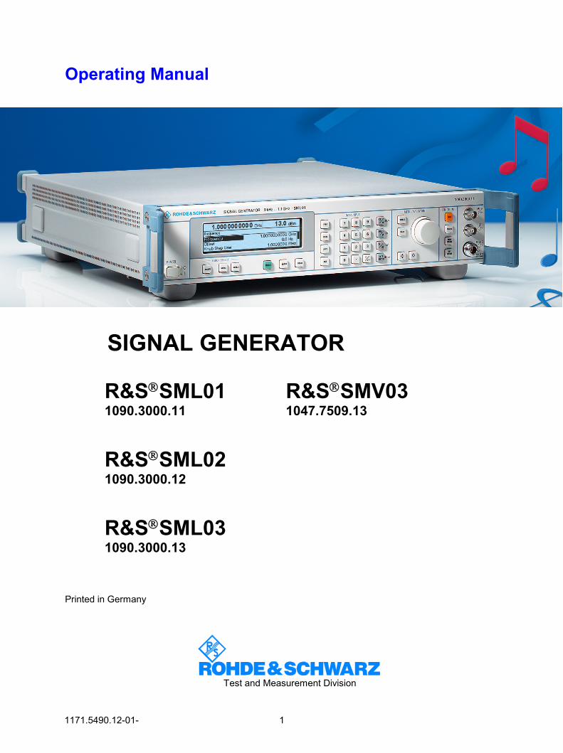
Operating Manual
SIGNAL GENERATOR
R&SSML01
1090.3000.11
R&SSML02 1090.3000.12
R&SSML03 1090.3000.13
R&SSMV03 1047.7509.13
Printed in Germany
Test and Measurement Division

Dear Customer, hroughout this manual, R&S® SML and R&S® SMV03 are abbreviated as R&S SML and R&S SMV03. R&S® is a registered trademark of Rohde & Schwarz GmbH & Co. KG. Trade names are trademarks of the owners.
R&S®SML / R&S®SMV03 Tabbed Divider Overview
1090.3123.12 RE E-6
Tabbed Divider Overview
Contents Index Data Sheet Safety Instructions Certificate of Quality EC Certificate of Conformity List of R&S Representatives Short Tutorial About How to Use the Manual
Divider
1 Chapter 1 Preparation for Use
2 Chapter 2 Introduction to Operation
3 Chapter 3 Manual Operation
4 Chapter 4 Functions
5 Chapter 5 Remote Control – Basics
6 Chapter 6 Remote Control – Commands
7 Chapter 7 Remote Control – Programming Examples
8 Chapter 8 Maintenance
9 Chapter 9 Error Messages
10 Chapter 10 Performance Test

R&S®SML / R&S®SMV03 Contents
1090.3123.12 3 E-6
Contents
1 Putting into Operation ........................................................................................ 1.1 General Instructions ...................................................................................................................1.1
Unpacking the Instrument ........................................................................................................1.1 Setting up the Instrument .........................................................................................................1.2 Cleaning the Outside and Storing ............................................................................................1.2
Supply Voltage.............................................................................................................................1.3 How to Ensure EMC ....................................................................................................................1.3 Power Fuses ................................................................................................................................1.3 Switching On/Off the Instrument ...............................................................................................1.3
Initial Status..............................................................................................................................1.3 RAM With Battery Back-Up.........................................................................................................1.4 Preset Setting ..............................................................................................................................1.4 Functional Test............................................................................................................................1.4 Mounting into a 19" Rack ...........................................................................................................1.4 Explanation of Front and Rear Panel ........................................................................................1.5
Elements of the Front Panel.....................................................................................................1.5 Elements of the Rear Panel ...................................................................................................1.10
2 Short Tutorial....................................................................................................... 2.1 Sample Setting for First Users...................................................................................................2.1
3 Manual Operation................................................................................................ 3.1 Design of the Display..................................................................................................................3.1 Basic Operating Steps ................................................................................................................3.2
Calling the menus.....................................................................................................................3.2 Selection and Change of Parameters ......................................................................................3.3 Quick Selection of Menu (QUICK SELECT) ............................................................................3.4 Use of [FREQ] and [LEVEL] Keys............................................................................................3.5 Use of [RF ON/OFF] and [MOD ON/OFF] ...............................................................................3.5 Changing Unit of Level .............................................................................................................3.5 Correction of Input....................................................................................................................3.6
List Editor.....................................................................................................................................3.7 Select List.................................................................................................................................3.8 Delete List ................................................................................................................................3.8 Edit List.....................................................................................................................................3.9
Storing/Calling of Instrument Settings....................................................................................3.14 Menu Summary for R&S SML...................................................................................................3.15 Menu Summary for R&S SMV03 ..............................................................................................3.16
Contents R&S®SML / R&S®SMV03
1090.3123.12 4 E-6
4 Instrument Functions.......................................................................................... 4.1 RF Frequency...............................................................................................................................4.1
Frequency Offset......................................................................................................................4.2 Extended Divider Range ..........................................................................................................4.2
RF Level........................................................................................................................................4.3 Level Offset ..............................................................................................................................4.5 Non-Interrupting Level Setting..................................................................................................4.5 Switching On/Off Automatic Level Control (ALC).....................................................................4.6 User Correction (Ucor) .............................................................................................................4.7 [RF ON/OFF] Key.....................................................................................................................4.8
Modulation - General...................................................................................................................4.9 Modulation Sources..................................................................................................................4.9 Simultaneous Modulation .......................................................................................................4.10 Mutual Switch-Off of Modulation Types..................................................................................4.10 [MOD ON/OFF] Key ...............................................................................................................4.10
Analog Modulations ..................................................................................................................4.11 Amplitude Modulation.............................................................................................................4.11 Frequency Modulation............................................................................................................4.12 Phase Modulation ................................................................................................................4.13 Pulse Modulation (Option R&S SML-B3) ...............................................................................4.14 Stereo Modulation (Option R&S SML-B5)..............................................................................4.17
Vector Modulation (R&S SMV03 only).....................................................................................4.43 I/Q IMPAIRMENT...................................................................................................................4.45
LF Generator..............................................................................................................................4.46 LF Output ...................................................................................................................................4.46 PULSE/VIDEO Output ...............................................................................................................4.47 Sweep .........................................................................................................................................4.49
Setting the Sweep Range (Start Freq, Stop Freq, Center Freq, Span)..................................4.49 Selecting Linear or Logarithmic Sweep (Spacing Lin, Log)....................................................4.50 Operating Modes (Mode) .......................................................................................................4.50 Sweep Inputs..........................................................................................................................4.51 RUN........................................................................................................................................4.51 RF Sweep...............................................................................................................................4.51 Level Sweep...........................................................................................................................4.53 LF Sweep ...............................................................................................................................4.54
Utilities........................................................................................................................................4.55 Display....................................................................................................................................4.55 System ...................................................................................................................................4.56 Internal/External Reference Frequency (RefOsc) ..................................................................4.59 Phase of the Output Signal ....................................................................................................4.60 Passwords for Accessing Protected Functions (Protect) .......................................................4.61 Calibration (Calib)...................................................................................................................4.62 Display of Module Versions (Diag - Config) ...........................................................................4.63 Display of Voltages of Test Points (Diag - TPoint) .................................................................4.64
R&S®SML / R&S®SMV03 Contents
1090.3123.12 5 E-6
Display of Service Data (Diag - Param) .................................................................................4.65 Test ........................................................................................................................................4.66 Assigning Modulations to the [MOD ON/OFF] Key (ModKey)................................................4.67 Setting the Sweep Blank Time ...............................................................................................4.68
Status..........................................................................................................................................4.69
5 Remote Control – Basic Information ................................................................. 5.1 Brief Instructions.........................................................................................................................5.1
IEC/IEEE Bus ...........................................................................................................................5.1 RS-232-C Interface ..................................................................................................................5.2
Switchover to Remote Control...................................................................................................5.3 Remote Control via IEC/IEEE Bus ...........................................................................................5.3 Remote Control via RS-232-C Interface ..................................................................................5.4
Messages .....................................................................................................................................5.5 Interface Messages..................................................................................................................5.5 Device Messages (Commands and Device Responses).........................................................5.5
Structure and Syntax of Device Messages...............................................................................5.6 Introduction to SCPI .................................................................................................................5.6 Structure of Commands ...........................................................................................................5.6 Structure of Command Lines ...................................................................................................5.9 Responses to Queries..............................................................................................................5.9 Parameters.............................................................................................................................5.10 Overview of Syntax Elements ................................................................................................5.12
Instrument Model and Command Processing........................................................................5.13 Input Unit ................................................................................................................................5.13 Command Recognition...........................................................................................................5.14 Data Set and Instrument Hardware........................................................................................5.14 Status Reporting System........................................................................................................5.14 Output Unit .............................................................................................................................5.15 Command Sequence and Command Synchronization ..........................................................5.15
Status Reporting System..........................................................................................................5.16 Structure of an SCPI Status Register.....................................................................................5.16 Overview of Status Registers .................................................................................................5.18 Description of Status Registers..............................................................................................5.19 Use of Status Reporting System ............................................................................................5.22 Reset Values of Status Reporting System .............................................................................5.24
Interfaces....................................................................................................................................5.25 IEC/IEEE-Bus Interface..........................................................................................................5.25 RS-232-C Interface ................................................................................................................5.28
Contents R&S®SML / R&S®SMV03
1090.3123.12 6 E-6
6 Remote Control – Description of Commands................................................... 6.1 Notation........................................................................................................................................6.1 Common Commands ..................................................................................................................6.3 ABORt System .............................................................................................................................6.6 CALibration System ....................................................................................................................6.6 DIAGnostic System .....................................................................................................................6.8 DISPLAY System .......................................................................................................................6.10 MEMory System.........................................................................................................................6.11 OUTPut System .........................................................................................................................6.11 SOURce System ........................................................................................................................6.13
SOURce:AM Subsystem ........................................................................................................6.13 SOURce:CORRection Subsystem .........................................................................................6.15 SOURce:DM Subsystem (R&S SMV03) ................................................................................6.17 SOURce:FM Subsystem ........................................................................................................6.19 SOURce:FREQuency Subsystem..........................................................................................6.21 SOURce:PHASe Subsystem..................................................................................................6.24 SOURce:PM Subsystem ........................................................................................................6.25 SOURce:POWer Subsystem .................................................................................................6.27 SOURce:PULM Subsystem ...................................................................................................6.30 SOURce:PULSe Subsystem ..................................................................................................6.31 SOURce:ROSCillator Subsystem ..........................................................................................6.33 SOURce:STEReoSubsystem.................................................................................................6.34 SOURce:SWEep Subsystem .................................................................................................6.38
SOURce2 System ......................................................................................................................6.41 SOURce2:FREQuency Subsystem........................................................................................6.41 SOURce2:SWEep Subsystem ...............................................................................................6.43
STATus System .........................................................................................................................6.45 SYSTem System ........................................................................................................................6.46 TEST System..............................................................................................................................6.49 TRIGger System.........................................................................................................................6.50 UNIT System ..............................................................................................................................6.52 List of Commands .....................................................................................................................6.53
R&S®SML / R&S®SMV03 Contents
1090.3123.12 7 E-6
7 Remote Control - Programming Examples ....................................................... 7.1 Including IEC-Bus Library for QuickBasic................................................................................7.1 Initialization and Default Status.................................................................................................7.1
Initiate Controller ......................................................................................................................7.1 Initiate Instrument.....................................................................................................................7.1
Transmission of Instrument Setting Commands .....................................................................7.2 Switchover to Manual Control ...................................................................................................7.2 Reading out Instrument Settings...............................................................................................7.2 Command synchronization ........................................................................................................7.3 Service Request...........................................................................................................................7.4
8 Maintenance ........................................................................................................ 8.1 Storing and Packing....................................................................................................................8.1 Exchanging the Lithium Battery ................................................................................................8.1
9 Error Messages ................................................................................................... 9.1 List of Error Messages................................................................................................................9.2
SCPI-Specific Error Messages.................................................................................................9.2 R&S SML / R&S SMV03-Specific Error Messages ..................................................................9.6
Possible Error Sources...............................................................................................................9.8
Contents R&S®SML / R&S®SMV03
1090.3123.12 8 E-6
10 Performance Test............................................................................................... 10.1 General .......................................................................................................................................10.1 Measuring equipment and accessories ..................................................................................10.2 Test setups ................................................................................................................................10.3
Standard test setup ................................................................................................................10.3 Test setup for setting time .......................................................................................................10.3
Test setup for SSB phase noise.............................................................................................10.4 Test setup for output reflection coefficient .............................................................................10.4 Test setup for pulse modulator option R&S SML-B3 .............................................................10.5 Test setup for stereo coder option R&S SML-B5 ...................................................................10.5
Test sequence ...........................................................................................................................10.6 Display and keyboard .............................................................................................................10.6 Frequency ..............................................................................................................................10.6 Reference frequency..............................................................................................................10.8 Spectral purity.........................................................................................................................10.9 Residual FM .........................................................................................................................10.12 Residual AM .........................................................................................................................10.12 Level.....................................................................................................................................10.13 Overvoltage protection .........................................................................................................10.18 Internal modulation generator ..............................................................................................10.18 Amplitude modulation...........................................................................................................10.19 AM total harmonic distortion.................................................................................................10.21 Frequency modulation..........................................................................................................10.22 FM total harmonic distortion.................................................................................................10.23 Phase modulation.................................................................................................................10.26 Pulse modulation (option R&S SML-B3) ..............................................................................10.28 Stereo modulation (option R&S SML-B5).............................................................................10.30
Performance test report..........................................................................................................10.34
Performance test - extension for R&S SMV03 .................................................. 10.38 Preliminary remark ..................................................................................................................10.38 Measuring equipment and accessorie ..................................................................................10.38 Test setups ..............................................................................................................................10.40
Standard test setup ..............................................................................................................10.40 Test sequence .........................................................................................................................10.41
Settig time ............................................................................................................................10.41 Spectral purity.......................................................................................................................10.41 Level.....................................................................................................................................10.43 Vector modulation ................................................................................................................10.44
Performance test report..........................................................................................................10.49
R&S®SML / R&S®SMV03 Contents
1090.3123.12 9 E-6
Tables Table 4-1 Overview of internal calibration routines ...................................................................... 4.62
Table 5-1 Synchronization by means of *OPC, *OPC? and *WAI ............................................... 5.15 Table 5-2 Meaning of the bits used in the status byte.................................................................. 5.19 Table 5-3 Meaning of the bits used in the event status register................................................... 5.20 Table 5-4 Resetting of instrument functions................................................................................. 5.24 Table 5-5 Interface functions........................................................................................................ 5.26 Table 5-6 Universal commands ................................................................................................... 5.27 Table 5-7 Addressed commands ................................................................................................. 5.27 Table 5-8 Control characters for RS-232-C interface .................................................................. 5.29
Table 6-1 Common Commands..................................................................................................... 6.3 Table 6-2 Device Response to *OPT? ........................................................................................... 6.4
Table 9-1 Error messages of hardware monitoring........................................................................ 9.8 Table 9-2 Error messages as a result of loss of data .................................................................... 9.8
Table 10-1 Maximum frequencies.................................................................................................. 10.1 Table 10-2 Measuring equipment and accessories ....................................................................... 10.2 Table 10-3 Measuring the frequency setting time .......................................................................... 10.7 Table 10-4 Performance test report ............................................................................................. 10.34 Table 10-5 Measuring equipment and accessories ..................................................................... 10.38 Table 10-6 Performance Test Report .......................................................................................... 10.49
Contents R&S®SML / R&S®SMV03
1090.3123.12 10 E-6
Figures Fig. 1-1 Front panel view.............................................................................................................1.5 Fig. 1-2 Rear panel view ...........................................................................................................1.10 Fig. 1-2 Rear panel view ...........................................................................................................1.11 Fig. 2-1 Display for AM setting ....................................................................................................2.3 Fig. 2-2 Display for pattern setting ..............................................................................................2.5 Fig. 3-1 Design of the display......................................................................................................3.1 Fig. 3-2 Modulation - AM Menu ...................................................................................................3.2 Fig. 3-3 Level - UCor menu.........................................................................................................3.7 Fig. 3-4 Select List window..........................................................................................................3.8 Fig. 3-5 Delete List window .........................................................................................................3.8 Fig. 3-6 Edit function Insert .......................................................................................................3.10 Fig. 3-7 Fill editing function .......................................................................................................3.11 Fig. 3-8 Edit editing function......................................................................................................3.12 Fig. 3-9 Delete editing function..................................................................................................3.13 Fig. 4-1 Frequency menu ............................................................................................................4.1 Fig. 4-2 Typical setups with frequency offset ..............................................................................4.2 Fig. 4-3 Level menu.....................................................................................................................4.3 Fig. 4-4 Typical setup with level offset ........................................................................................4.5 Fig. 4-5 Level - ALC menu (preset setting) .................................................................................4.6 Fig. 4-6 Level - ALC - State Off ...................................................................................................4.6 Fig. 4-7 Level - UCor menu.........................................................................................................4.7 Fig. 4-8 UCor - Level menu.........................................................................................................4.8 Fig. 4-9 Modulation - AM menu (preset setting)........................................................................4.11 Fig. 4-10 Modulation - FM menu (preset setting) ........................................................................4.12 Fig. 4-11 Modulation - ΦM menu (preset setting) .......................................................................4.13 Fig. 4-12 Modulation - Pulse menu (preset setting), equipped with option R&S SML-B3...........4.14 Fig. 4-13 Signal example 1: single pulse, Pulse mode = Auto Trig.............................................4.16 Fig. 4-14 Signal example 2: double pulse, Pulse mode = Ext Trig, Slope = Pos ........................4.16 Fig. 4-15 Signal example 3: single pulse, Pulse Mode = Ext Gated ...........................................4.16 Fig. 4-16 Modulation - Stereo menu (preset setting), equipped with option R&S SML-B5 ........4.17 Fig. 4-15 Example: vector modulation.........................................................................................4.43 Fig. 4-16 VECTOR MOD menu (preset settings) R&S SMV03 ..................................................4.43 Fig. 4-17 LF Output menu (preset setting) ..................................................................................4.46 Fig. 4-18 Pulse Output menu ......................................................................................................4.47 Fig. 4-19 Sweep - Freq menu .....................................................................................................4.51 Fig. 4-20 Sweep - Level menu ....................................................................................................4.53 Fig. 4-21 Sweep - LFGen menu..................................................................................................4.54 Fig. 4-22 Utilities menu................................................................................................................4.55 Fig. 4-23 Utilities - Display menu.................................................................................................4.55 Fig. 4-24 Utilities - System menu ................................................................................................4.56 Fig. 4-25 Utilities – System – GPIB – Address menu..................................................................4.56
R&S®SML / R&S®SMV03 Contents
1090.3123.12 11 E-6
Fig. 4-26 Utilities – System – RS232 menu.................................................................................4.57 Fig. 4-27 Utilities – System – Security menu...............................................................................4.58 Fig. 4-28 Utilities – RefOsc menu (preset setting) ......................................................................4.59 Fig. 4-29 Menu Utilities – Phase .................................................................................................4.60 Fig. 4-30 Utilities - Protect menu (preset setting)........................................................................4.61 Fig. 4-31 Utilities - Calib menu (preset setting) ...........................................................................4.62 Fig. 4-32 Utilities - Diag - Config menu .......................................................................................4.63 Fig. 4-33 Utilities - Diag - TPoint menu .......................................................................................4.64 Fig. 4-34 Utilities - Diag - Param menu .......................................................................................4.65 Fig. 4-35 Utilities - Test menu .....................................................................................................4.66 Fig. 4-36 Utilities - ModKey menu (preset setting) ......................................................................4.67 Fig. 4-38 STATUS menu.............................................................................................................4.69 Fig. 5-1 Tree structure of SCPI command systems using the SOURce system
as an example................................................................................................................5.7 Fig. 5-2 Device model for remote control via the IEC/IEEE bus ...............................................5.13 Fig. 5-3 Status register model ...................................................................................................5.16 Fig. 5-4 Overview of status registers.........................................................................................5.18 Fig. 5-5 Pin assignment of IEC/IEEE-bus interface ..................................................................5.25 Fig. 5-6 Pin assignment of RS-232-C interface.........................................................................5.28 Fig. 5-7 Wiring of data, control and signalling lines for hardware handshake...........................5.30 Fig. 9-1 ERROR page .................................................................................................................9.1

R&S®SML / R&S®SMV03 Index
1090.3123.12 I.1 E-6
Index
AAbort actions triggered........................................................ 6.6 Active edge ..................................................... 4.18, 4.48, 6.52 Address
IEC/IEEE bus ...................................................... 5.3, 6.47 Addressed commands ...................................................... 5.27 AM
coupling ............................................................. 4.14, 6.14 frequency........................................................... 4.14, 6.14
Amplitude modulation (AM)...................................... 4.14, 6.13 Asterisk ............................................................................. 5.12 Attenuator .................................................................. 4.5, 6.11
BBandwidth
FM ..................................................................... 4.15, 6.20 PM..................................................................... 4.16, 6.26
Battery Exchanging .............................................................1.4, 8.1 Test RAM ................................................................... 4.66
Baud rate (RS-232-C) ..................................... 4.57, 5.29, 6.48 Blank signal
duration....................................................................... 4.68 Block data........................................................................ 5.11 Boolean parameters................................................... 5.9, 5.10 Brief instructions
IEC/IEEE bus ............................................................... 5.1 RS-232-C interface....................................................... 5.2
CCalibration.................................................................. 4.62, 6.6
disable ........................................................................ 6.49 password........................................................... 4.61, 6.49
Call instrument settings ..................................................... 3.14 menu ............................................................................ 3.4
Center frequency RF sweep .......................................................... 4.52, 6.21
Character data .................................................................... 5.9 Cleaning
outside.......................................................................... 8.1 Clear
all stored data............................................................. 4.58 memories.................................................................... 4.58
Colon................................................................................. 5.12 Comma ............................................................................. 5.12 Command
addressed commands................................................ 5.27 common commands....................................... 5.5, 5.6, 6.3 device-specific commands .................................... 5.5, 5.6 hierarchical arrangement.............................................. 6.1 long form....................................................................... 5.7 parameters ................................................................. 5.10 path .............................................................................. 5.6 Processing.................................................................. 5.13 queries.......................................................................... 5.5
recognition ..................................................................5.14 sequence ....................................................................5.15 setting commands.........................................................5.5 short form......................................................................5.7 structure ........................................................................5.6 structure of command lines...........................................5.9 synchronization ....................................................5.15, 7.3 syntax elements..........................................................5.12 universal commands...................................................5.27
Command Error bit ............................................................5.20 Command lines
structure ........................................................................5.9 Common commands ...........................................................6.3 CONDition part ..................................................................5.17 Control signal (pulse modulation) ......................................4.17 Coupling
external input (AM).............................................4.14, 6.14 external input (FM).............................................4.15, 6.19 external input (PM).............................................4.16, 6.25
Crosshatch symbol (#)..............................................5.11, 5.12 Cursor
digit cursor ....................................................................3.1 menu cursor ..................................................................3.1
DData
format (RS-232-C).......................................................4.57 set (IEC/IEEE bus)......................................................5.14
Data bit (RS-232-C)...........................................................5.29 DC offset compensation .............................................4.15, 6.7 DCL ...................................................................................5.13 Decimal point..............................................................1.6, 5.10 Delay
double pulse................................................................6.31 pulse modulation.......................................4.17, 4.47, 6.31
Delete list..................................................................................3.8 list entry.......................................................................3.13
Deviation FM......................................................................4.15, 6.19 PM......................................................................4.16, 6.25
Device model (IEC/IEEE bus) ...........................................5.13 Device responses................................................................5.5 Device-Dependent Error bit ...............................................5.20 Digit cursor ..........................................................................3.1 Disable
indications ...................................................................4.58 Display.................................................................................3.1
contrast .......................................................................4.55 modules ......................................................................4.63 operating-hours counter..............................................4.65 serial number ..............................................................4.65 software version..........................................................4.65 voltage of test points ...................................................4.64
Double pulse....................................................4.18, 4.48, 6.31 Dwell time
frequency sweep................................................4.52, 6.39 level sweep ........................................................4.53, 6.40
Index R&S®SML / R&S®SMV03
1090.3123.12 I.2 E-6
EEdge
external trigger............................................................ 6.52 Edit
list ................................................................................. 3.9 list entry ...................................................................... 3.12
EMC.................................................................................... 1.3 ENABle part ...................................................................... 5.17 Envelope........................................................................... 4.17 EOI (command line) ............................................................ 5.9 EPROM, test..................................................................... 4.66 Error messages.......................................................... 6.49, 9.2
device-specific.............................................................. 9.1 SCPI-specific................................................................ 9.2
Error queue .............................................................. 6.46, 6.48 query .......................................................................... 5.23
Error Queue Not Empty bit................................................ 5.19 Error vector
vector modulation ..................................................... 10.45 ESB bit .............................................................................. 5.19 ESE (event status enable register) ................................... 5.20 ESR (event status register)............................................... 5.20 EVENt part ........................................................................ 5.17 Event status register (ESR) .............................................. 5.20 Execution Error bit ............................................................ 5.20 Exponent........................................................................... 5.10 External trigger
active edge............................................... 4.18, 4.48, 6.52 pulse modulation ...................................... 4.18, 4.48, 6.52
FFill
list entry ...................................................................... 3.11 FM
bandwidth .......................................................... 4.15, 6.20 coupling ............................................................. 4.15, 6.19 DC offset compensation...................................... 4.15, 6.7 deviation ............................................................ 4.15, 6.19 frequency........................................................... 4.15, 6.20 Hub.................................................................... 6.17, 6.18
Frequency accuracy....................................................................... 1.3 adjustment......................................................... 4.59, 6.33 AM..................................................................... 4.14, 6.14 correction value ................................................. 4.59, 6.33 FM ..................................................................... 4.15, 6.20 indication ...................................................................... 3.1 LF generator............................................................... 6.42 LF sweep.................................................................... 6.43 offset............................................................. 4.1, 4.2, 6.22 PM..................................................................... 4.16, 6.26 RF output signal ......................................................... 6.21 suppression of indication............................................ 4.58
Frequency modulation (FM)............................ 4.15, 6.17, 6.19 Frequency sweep
LF ...................................................................... 4.54, 6.44 RF...................................................................... 4.52, 6.22
Frequenz Offset............................................................................ 4.2
Front panel.......................................................................... 1.5 Functional test..................................................................... 1.4 Fuse holder ....................................................................... 1.11
GGate signal
trigger........................................................4.18, 4.22, 4.48 GET (Group Execute Trigger) ...........................................5.14
HHandshake (RS-232-C)...................................4.57, 5.30, 6.48 Header (commands)............................................................5.6 Header field (display)...........................................................3.1
II/Q
modulation ..................................................................4.43 I/Q Imbalance
test sequence............................................................10.47 IEC/IEEE bus
address ..............................................................4.56, 6.47 brief instructions............................................................5.1 bus lines......................................................................5.25 interface .............................................................1.11, 5.25 language .....................................................................4.58 library ............................................................................7.1 setting of address..........................................................5.3
Imbalance..........................................................................4.44 Impairment................................................................4.44, 4.45 Indication
error messages ...........................................................6.46 modules ........................................................................6.8 operating-time counter ..................................................6.8 remote control ........................................................5.3, 5.4 RF OFF.......................................................................4.10 software version............................................................6.9 suppression of.............................................................4.58
INF.....................................................................................5.10 Initial status..........................................................................1.3 Initialization
controller .......................................................................7.1 instrument .....................................................................7.1
Input correction ......................................................................3.6 external modulation signal ............................................1.8 frequency ......................................................................3.5 internal (AM) ......................................................4.14, 6.14 internal (FM).......................................................4.15, 6.20 internal (PM) ......................................................4.16, 6.25 level...............................................................................3.5 MOD..............................................................................1.8 PULSE ............................................................... 1.10, 6.52 REF....................................................................1.10, 4.59 TRIGGER ...................................................................1.10
Input buffer ........................................................................5.13 Input unit............................................................................5.13 Insert
list entry.........................................................................3.9 Instrument states
reset ............................................................................ 6.49 Instrument setting commands
transmission..................................................................7.2 Instrument settings
call...............................................................................3.14 reading out ....................................................................7.2
R&S®SML / R&S®SMV03 Index
1090.3123.12 I.3 E-6
store ........................................................................... 3.14 Interface
functions (IEC/IEEE bus) ........................................... 5.26 functions (RS-232-C).................................................. 5.29 IEC/IEEE bus .................................................... 1.11, 5.25 messages (IEC/IEEE bus) ......................................... 5.27 RS-232-C .......................................................... 1.10, 5.28
Internal reference.............................................................. 4.59 Interrupt............................................................................. 5.19 Inverted commas .............................................................. 5.12 IST flag.............................................................................. 5.20
KKey
[-/←] .......................................................................1.6, 3.6 [ASSIGN]............................................................... 1.9, 3.4 [BACK]................................................................... 3.2, 3.6 [BACK] ..........................................................................1.7 [ERROR] ...................................................................... 9.1 [FREQ] .................................................... 1.5, 3.5, 3.6, 4.1 [G/n] ..............................................................................1.6 [LEVEL] ................................................... 1.5, 3.5, 3.6, 4.4 [LOCAL]........................................................................ 5.4 [M/µ] ..............................................................................1.6 [MENU 1/2]............................................................ 1.9, 3.4 [MOD ON/OFF] ................................... 1.8, 3.5, 4.13, 4.67 [PRESET]..................................................................... 1.4 [RCL] ................................................................... 1.5, 3.14 [RF ON/OFF]................................................ 1.8, 3.5, 4.10 [SAVE]................................................................. 1.5, 3.14 [SELECT] ..................................................................... 3.2 [SELECT] ......................................................................1.7 [STATUS] ................................................................... 4.69 [⇐/⇒] ............................................................................1.7 Backspace.................................................................... 3.6 ERROR ........................................................................ 1.8 HELP............................................................................ 1.8 k/m................................................................................ 1.6 LOCAL.......................................................................... 1.8 PRESET....................................................................... 1.8 STATUS....................................................................... 1.8 unit key ......................................................................... 1.6 X1/Enter ....................................................................... 1.6
Knob Step frequency...................................................................... 4.2 level .............................................................................. 4.5
LLeakage ............................................................................ 4.44 Level
automatic control ................................................. 4.7, 6.27 correction (Ucor list) ............................................ 4.9, 6.15 indication ...................................................................... 3.1 limit ...................................................................... 4.4, 6.28 offset............................................................. 4.4, 4.6, 6.28 RF output............................................................. 4.4, 6.28 setting (non-interrupting) ....................................... 4.5, 4.6 suppression of indication............................................ 4.58 sweep......................................................................... 4.53 unit................................................................................ 4.4 unit change................................................................... 3.5
Level sweep
dwell time...........................................................4.53, 6.40 start level............................................................4.53, 6.29 step width...........................................................4.53, 6.41 stop level............................................................4.53, 6.29 sweep mode..............................................4.53, 6.28, 6.40
LF generator .............................................................4.46, 6.42 LF output ....................................................................1.8, 4.46
voltage ........................................................................4.46 LF sweep..................................................................4.54, 6.43
dwell time...........................................................4.54, 6.44 frequency ...........................................................4.54, 6.44 start frequency ...................................................4.54, 6.43 step size.............................................................4.54, 6.45 stop frequency ...................................................4.54, 6.43 sweep modes.....................................................4.54, 6.44
List delete ............................................................................3.8 edit ................................................................................3.9 error messages .............................................................9.2 level correction (Ucor)..........................................4.9, 6.15 select.............................................................................3.8
List entry delete ..........................................................................3.13 edit ..............................................................................3.12 fill.................................................................................3.11 insert .............................................................................3.9
Lock level...........................................................................4.61 Long form (commands) .......................................................5.7 Lower-case notation (commands) .......................................5.7
MMaintenance........................................................................8.1 Mantissa ............................................................................5.10 Manual control
switchover.....................................................................7.2 Manual operation
return to.........................................................................5.4 MAV bit..............................................................................5.19 Maximum value (commands) .....................................5.9, 5.10 Measurement
quadrature.................................................................10.48 Measuring equipment and accessories (performance test)................................................................................10.2, 10.38 Memory
CMOS-RAM .................................................................. 1.4 locations.............................................................3.14, 6.11
Menu access...........................................................................3.2 call.................................................................................3.4 ERROR.........................................................................9.1 fields..............................................................................3.1 Frequency.....................................................................4.1 Level - Alc .....................................................................4.7 Level - Ucor..........................................................4.9, 4.10 LfOutput ......................................................................4.46 Modulation - AM............................................................3.2 Modulation - FM..........................................................4.15 Modulation - Pulse .............................................4.17, 4.20 PulseOutput ................................................................4.47 quick selection ..............................................................3.4 Status..........................................................................4.69 store ..............................................................................3.4 summary ............................................................3.15, 3.16 Sweep - Freq ..............................................................4.51 Sweep - Level .............................................................4.53 Sweep - LFGen...........................................................4.54 Utilities ........................................................................4.55
Index R&S®SML / R&S®SMV03
1090.3123.12 I.4 E-6
Utilities – AuxIO.......................................................... 4.68 Utilities - Calib............................................................. 4.62 Utilities - Diag - Config................................................ 4.63 Utilities - Diag - Param................................................ 4.65 Utilities – Diag - TPoint............................................... 4.64 Utilities - Display......................................................... 4.55 Utilities - ModKey ....................................................... 4.67 Utilities - Protect ......................................................... 4.61 Utilities – RefOsc........................................................ 4.59 Utilities - System......................................................... 4.56 Utilities – System – Language.................................... 4.58 Utilities – System – RS232......................................... 4.57 Utilities – System – Security....................................... 4.58 Utilities - Test.............................................................. 4.66 VECTOR MOD........................................................... 4.43
Menu cursor........................................................................ 3.1 Message OVEN COLD....................................................... 1.3 Messages
device messages.......................................................... 5.5 interface messages ...................................................... 5.5
Minimum value (commands)...................................... 5.9, 5.10 MOD
coupling .................................................... 4.14, 4.15, 4.16 input.............................................................................. 1.8
Modulation AM..................................................................... 4.14, 6.13 FM ............................................................ 4.15, 6.17, 6.19 I/Q............................................................................... 4.43 incompatible modulation types ................................... 4.13 inputs.......................................................................... 4.11 overview of modulation types..................................... 4.11 PM............................................................ 4.16, 6.25, 6.34 Pulse ................................................................. 4.17, 6.30 vector.......................................................................... 4.43
Modulation depth AM..................................................................... 4.14, 6.13
Modulation source external....................................................................... 4.11 internal........................................................................ 4.11
Modulation types switching-on/off .......................................................... 4.67
........................................................................ 4.20, 4.22, 4.23 ................................................................................... 4.11
................................................................................... 4.11
Modules indication .............................................................. 6.8 MSS bit ............................................................................. 5.19
NNAN .................................................................................. 5.10 New Line (command line) ................................................... 5.9 NINF.................................................................................. 5.10 Non-interrrupting level setting ............................................. 4.5 Note
Unleveled ..................................................................... 4.4 NTRansition part ............................................................... 5.17 Numeric input field .............................................................. 1.6 Numeric values ................................................................... 1.6 Numerical suffix .................................................................. 5.8 Numerical values .............................................................. 5.10
OOffset
frequency ......................................................................4.1 level...............................................................................4.4
On/Off switch.......................................................................1.5 Operating-time counter...............................................4.65, 6.8 Operation
EMC..............................................................................1.3 general instructions.......................................................1.1 manual control ..............................................................4.1 putting into operation.....................................................1.1 remote control ...............................................................6.1 unpacking......................................................................1.1
Operation Complete bit......................................................5.20 OPERation Status Register sum bit ..................................5.19 Output
LF................................................................1.8, 4.46, 6.12 PULSE/VIDEO...................................................1.10, 4.47 REF....................................................................1.10, 4.59 RF ........................................................................1.8, 6.21
Output buffer (IEC/IEEE bus) ............................................5.15 Output level ................................................................4.4, 6.27 Output unit (IEC/IEEE bus) ...............................................5.15 Overlapping execution.......................................................5.14 Overview
Status registers ...........................................................5.18 syntax elements..........................................................5.12
PPacking................................................................................8.1 Parallel poll ........................................................................5.23 Parallel poll enable register (PPE).....................................5.20 Parameter
select.............................................................................3.3 text parameter.............................................................5.10
Parameters (commands)...................................................5.10 Parity (RS-232-C) .....................................................4.57, 6.47 Parity bit (RS-232-C) .........................................................5.29 Password...........................................................................6.49 Path (commands) ................................................................5.6 Performance test ...............................................................10.1
report.........................................................................10.49 Performance Test
Report .......................................................................10.34 Performance test - extension for R&S SMV03................10.38 Period (pulse) ...........................................................4.17, 4.47 Phase modulation (PM)...................................4.16, 6.25, 6.34 Physical quantities...............................................................5.9 PM
bandwidth...........................................................4.16, 6.26 coupling..............................................................4.16, 6.25 deviation.............................................................4.16, 6.25 frequency ...........................................................4.16, 6.26
Polarity pulse ................................................4.17, 4.47, 6.12, 6.30
Power fuses.........................................................................1.3 Power On bit......................................................................5.20 Power supply.......................................................................1.3 Power supply connector ....................................................1.11 PPE (parallel poll enable register) .....................................5.20 Preset (instrument settings).................................................1.4 Preset (instrument states)................................................... 6.49 Programming Examples ......................................................7.1 Protection level ..................................................................6.49 PTRansition part................................................................5.17
R&S®SML / R&S®SMV03 Index
1090.3123.12 I.5 E-6
Pulse delay......................................................... 4.17, 4.47, 6.31 period........................................................ 4.17, 4.47, 6.31 width ......................................................... 4.17, 4.47, 6.32
Pulse generator........................................................ 4.18, 6.31 PULSE input.....................................................1.10, 4.18, 6.52 Pulse modulation ..................................................... 4.17, 6.30 Pulse polarity ......................................... 4.17, 4.47, 6.12, 6.30 Pulse source
selection ................................................... 4.17, 4.47, 6.12 PULSE/VIDEO output.............................................. 1.10, 4.47
QQuadrature offset .............................................................. 4.44 Queries ............................................................................... 5.5 Query
error queue................................................................. 5.23 responses to................................................................. 5.9
Query Error bit .................................................................. 5.20 Question mark................................................................... 5.12 QUEStionable Status sum bit ........................................... 5.19 Quick selection.................................................................... 3.4
RRAM, test .......................................................................... 4.66 Rear panel ........................................................................ 1.10 Recall
instrument settings ..................................................... 3.14 REF
input/output........................................................ 1.10, 4.59 Reference
input/output................................................................. 6.33 internal........................................................................ 4.59
Reference oscillator OCXO...................................... 4.59, 6.33 Remote control.................................................................... 6.1
basic Information .......................................................... 5.1 indications .................................................................... 5.3 switchover to remote control ........................................ 5.3
REMOTE state.................................................................... 5.3 REMOTE SYNTAX ERRORS .......................................... 4.55 Reset
instrument settings ....................................................... 1.4 status reporting system .............................................. 5.24
Response to queries...................................................................... 5.9
RF frequency...................................................................... 4.1 level .............................................................................. 4.4 output level ................................................................. 6.28
RF output ............................................................................ 1.8 RF sweep................................................................. 4.51, 6.39
dwell time .......................................................... 4.52, 6.39 step width .......................................................... 4.52, 6.40
Rotary knob........................................................... 1.7, 3.2, 3.3 RS-232-C interface .................................................. 1.10, 5.28
brief instructions ........................................................... 5.2 signal lines.................................................................. 5.28 transmission parameters ............................................ 4.57
SSample setting.....................................................................2.1 Sample-and-Hold mode.......................................................4.7 Save
instrument settings......................................................3.14 SCPI
introduction ...................................................................5.6 Scrollbar ..............................................................................3.2 Select
list..................................................................................3.8 Selection
1-out-of-n.......................................................................3.4 quick selection of menu ................................................3.4
Self test.....................................................................4.66, 6.50 Semicolon..........................................................................5.12 Serial number (display)......................................................4.65 Serial poll...........................................................................5.22 Service data
display.........................................................................4.65 Service request (SRQ) ......................................................5.22 Service request enable register (SRE)..............................5.19 Service request SRQ) .........................................................7.4 Short form (commands).......................................................5.7 Sign ...................................................................................5.10 Single pulse delay ....................................................4.17, 4.47 Software version
display..................................................................4.65, 6.9 Source impedance (RF output) .........................................4.10 Span
RF sweep...........................................................4.52, 6.22 Special characters...............................................................6.2 Square brackets ..................................................................5.7 SRE (service request enable register)...............................5.19 SRQ (Service request) ......................................................5.22 Start frequency
LF sweep ...........................................................4.54, 6.43 RF sweep...........................................................4.52, 6.22
Status REMOTE ......................................................................5.3
Status line (display) .............................................................3.1 STATUS page ...................................................................4.69 Status registers
description...................................................................5.19 overview......................................................................5.18
Status reporting system.....................................................5.16 reset values.................................................................5.24 structure of an SCPI status register............................5.16 use ..............................................................................5.22
STB (status byte)...............................................................5.19 Step size
rotary knob.............................................................4.1, 4.5 Step width
level sweep ........................................................4.53, 6.41 LF sweep ...........................................................4.54, 6.45 RF sweep....................................................................6.22
Stop bit (RS-232-C) .........................................4.57, 5.29, 6.47 Stop frequency
LF sweep ...........................................................4.54, 6.43 RF sweep...........................................................4.52, 6.22
Store instrument settings......................................................3.14 menu.............................................................................3.4
Storing .................................................................................8.1 String .................................................................................5.11 Structure
command ......................................................................5.6 command lines..............................................................5.9
Subroutines .........................................................................7.5 Sum bit ..............................................................................5.17 Summary of menu ....................................................3.15, 3.16
Index R&S®SML / R&S®SMV03
1090.3123.12 I.6 E-6
Suppression indication .................................................................... 4.58
Sweep inputs.......................................................................... 4.51 level sweep........................................................ 4.53, 6.27 LF sweep........................................................... 4.54, 6.44 operating modes......................................................... 4.50 RF sweep ................................................. 4.51, 6.22, 6.39 trigger ......................................................................... 6.51
Synchronization (IEC/IEEE bus)....................................... 5.15 Syntax elements (IEC/IEEE bus)...................................... 5.12
TTerminator......................................................................... 5.13 Test
level .......................................................................... 10.43 Spectral purity .......................................................... 10.41
Test points ................................................................. 4.64, 6.9 Test sequence
I/Q Imbalance........................................................... 10.47 vector modulation ..................................................... 10.44
Test setup standard ................................................................... 10.40 vector modulation ..................................................... 10.40
Text parameter.................................................................. 5.10 Transmission parameters (RS-232-C) ....................... 5.4, 5.29 Transmission rate (RS-232-C) .......................................... 4.57 Trigger
active edge............................................... 4.18, 4.48, 6.52 Gate signal ........................................................ 4.18, 4.48 pulse modulation ...................................... 4.18, 4.48, 6.52 sweep................................................................ 4.51, 6.51
TRIGGER Input ................................................................ 1.10 Truth values ........................................................................ 5.9
UUcor (level correction) ................................................4.9, 6.15 Universal commands.........................................................5.27 Unlock
calibration....................................................................4.61 Unpacking............................................................................1.1 User correction (Ucor) ................................................4.9, 6.15 User Request.....................................................................5.22 User Request bit................................................................5.20
VValue
change ..........................................................................3.3 inputs ............................................................................3.3
Vector modulation..............................................................4.43
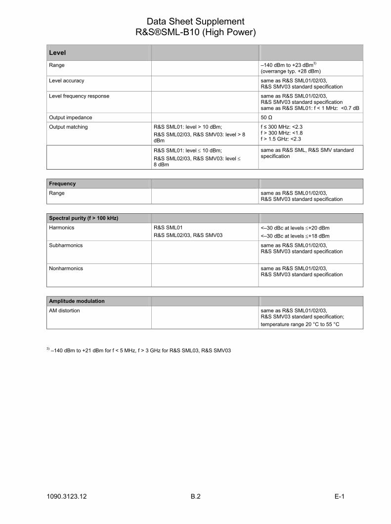
1090.3123.12 B.2 E-1
Data Sheet Supplement R&S®SML-B10 (High Power)
Level
Range –140 dBm to +23 dBm3)
(overrange typ. +28 dBm)
Level accuracy same as R&S SML01/02/03, R&S SMV03 standard specification
Level frequency response same as R&S SML01/02/03, R&S SMV03 standard specification same as R&S SML01: f < 1 MHz: <0.7 dB
Output impedance 50 Ω
Output matching R&S SML01: level > 10 dBm; R&S SML02/03, R&S SMV03: level > 8 dBm
f ≤ 300 MHz: <2.3 f > 300 MHz: <1.8 f > 1.5 GHz: <2.3
R&S SML01: level ≤ 10 dBm; R&S SML02/03, R&S SMV03: level ≤8 dBm
same as R&S SML, R&S SMV standard specification
Frequency
Range same as R&S SML01/02/03, R&S SMV03 standard specification
Spectral purity (f > 100 kHz)
Harmonics R&S SML01 R&S SML02/03, R&S SMV03
<–30 dBc at levels ≤+20 dBm <–30 dBc at levels ≤+18 dBm
Subharmonics same as R&S SML01/02/03, R&S SMV03 standard specification
Nonharmonics same as R&S SML01/02/03, R&S SMV03 standard specification
Amplitude modulation
AM distortion same as R&S SML01/02/03, R&S SMV03 standard specification; temperature range 20 °C to 55 °C
3) –140 dBm to +21 dBm for f < 5 MHz, f > 3 GHz for R&S SML03, R&S SMV03

1171.0000.42-03.00 Sheet 1
Before putting the product into operation for the first time, make sure to read the following
S a f e t y I n s t r u c t i o n s
All plants and locations of the Rohde & Schwarz group of companies make every effort to keep the safety standard of our products up to date and to offer our customers the highest possible degree of safety. Our products and the auxiliary equipment required for them are designed and tested in accordance with the relevant safety standards. Compliance with these standards is continuously monitored by our quality assurance system. The product described here has been designed and tested in accordance with the EC Certificate of Conformity and has left the manufacturers plant in a condition fully complying with safety standards. To maintain this condition and to ensure safe operation, observe all instructions and warnings provided in this manual. If you have any questions regarding these safety instructions, the Rohde & Schwarz group of companies will be happy to answer them.
Furthermore, it is your responsibility to use the product in an appropriate manner. This product is designed for use solely in industrial and laboratory environments or in the field and must not be used in any way that may cause personal injury or property damage. You are responsible if the product is used for an intention other than its designated purpose or in disregard of the manufacturer's instructions. The manufacturer shall assume no responsibility for such use of the product.
The product is used for its designated purpose if it is used in accordance with its product documentation and within its performance limits (see data sheet, documentation, the following safety instructions). Using the product requires technical skills and a basic knowledge of English. It is therefore essential that the product be used exclusively by skilled and specialized staff or thoroughly trained personnel with the required skills. If personal safety gear is required for using Rohde & Schwarz products, this will be indicated at the appropriate place in the product documentation.
Symbols and safety labels
Observe product documentation
Weight indication for units >18 kg
Danger of electric shock
Warning! Hot surface
PE terminal Ground Ground terminal
Attention! Electrostatic sensitive devices
Supply voltage ON/OFF
Standby indication
Direct current (DC)
Alternating current (AC)
Direct/alternating current (DC/AC)
Device fully protected by double/reinforced insulation
Safety Instructions
1171.0000.42-03.00 Sheet 2
Observing the safety instructions will help prevent personal injury or damage of any kind caused by dangerous situations. Therefore, carefully read through and adhere to the following safety instructions before putting the product into operation. It is also absolutely essential to observe the additional safety instructions on personal safety that appear in relevant parts of the product documentation. In these safety instructions, the word "product" refers to all merchandise sold and distributed by the Rohde & Schwarz group of companies, including instruments, systems and all accessories.
Tags and their meaning DANGER This tag indicates a definite hazard carrying a high risk of death or
serious injury if not avoided. WARNING This tag indicates a possible hazard carrying a medium risk of death or
(serious) injury if not avoided. CAUTION This tag indicates a hazard carrying a low risk of minor or moderate
injury if not avoided. ATTENTION This tag indicates the possibility of incorrect use that can cause damage
to the product. NOTE This tag indicates a situation where the user should pay special attention
to operating the product but which does not lead to damage.
These tags are in accordance with the standard definition for civil applications in the European Economic Area. Definitions that deviate from the standard definition may also exist in other economic areas or military applications. It is therefore essential to make sure that the tags described here are always used only in connection with the related product documentation and the related product. The use of tags in connection with unrelated products or documentation can result in misinterpretation and thus contribute to personal injury or material damage.
Basic safety instructions 1. The product may be operated only under
the operating conditions and in the positions specified by the manufacturer. Its ventilation must not be obstructed during operation. Unless otherwise specified, the following requirements apply to Rohde & Schwarz products: prescribed operating position is always with the housing floor facing down, IP protection 2X, pollution severity 2, overvoltage category 2, use only in enclosed spaces, max. operation altitude 2000 m above sea level, max. transport altitude 4500 m above sea level. Unless specified otherwise in the data sheet, a tolerance of ±10% shall apply to the nominal voltage and of ±5% to the nominal frequency.
2. Applicable local or national safety regulations and rules for the prevention of accidents must be observed in all work performed. The product may be opened only by authorized, specially trained personnel. Prior to performing any work on
the product or opening the product, the product must be disconnected from the supply network. Any adjustments, replacements of parts, maintenance or repair must be carried out only by technical personnel authorized by Rohde & Schwarz. Only original parts may be used for replacing parts relevant to safety (e.g. power switches, power transformers, fuses). A safety test must always be performed after parts relevant to safety have been replaced (visual inspection, PE conductor test, insulation resistance measurement, leakage current measurement, functional test).
3. As with all industrially manufactured goods, the use of substances that induce an allergic reaction (allergens, e.g. nickel) such as aluminum cannot be generally excluded. If you develop an allergic reaction (such as a skin rash, frequent sneezing, red eyes or respiratory difficulties), consult a physician immediately to determine the cause.
Safety Instructions
1171.0000.42-03.00 Sheet 3
4. If products/components are mechanically and/or thermically processed in a manner that goes beyond their intended use, hazardous substances (heavy-metal dust such as lead, beryllium, nickel) may be released. For this reason, the product may only be disassembled, e.g. for disposal purposes, by specially trained personnel. Improper disassembly may be hazardous to your health. National waste disposal regulations must be observed.
5. If handling the product yields hazardous substances or fuels that must be disposed of in a special way, e.g. coolants or engine oils that must be replenished regularly, the safety instructions of the manufacturer of the hazardous substances or fuels and the applicable regional waste disposal regulations must be observed. Also observe the relevant safety instructions in the product documentation.
6. Depending on the function, certain products such as RF radio equipment can produce an elevated level of electromagnetic radiation. Considering that unborn life requires increased protection, pregnant women should be protected by appropriate measures. Persons with pacemakers may also be endangered by electromagnetic radiation. The employer/operator is required to assess workplaces where there is a special risk of exposure to radiation and, if necessary, take measures to avert the danger.
7. Operating the products requires special training and intense concentration. Make certain that persons who use the products are physically, mentally and emotionally fit enough to handle operating the products; otherwise injuries or material damage may occur. It is the responsibility of the employer to select suitable personnel for operating the products.
8. Prior to switching on the product, it must be ensured that the nominal voltage setting on the product matches the nominal voltage of the AC supply network. If a different voltage is to be set, the power fuse of the product may have to be changed accordingly.
9. In the case of products of safety class I with movable power cord and connector, operation is permitted only on sockets with earthing contact and protective earth connection.
10. Intentionally breaking the protective earth connection either in the feed line or in the
product itself is not permitted. Doing so can result in the danger of an electric shock from the product. If extension cords or connector strips are implemented, they must be checked on a regular basis to ensure that they are safe to use.
11. If the product has no power switch for disconnection from the AC supply, the plug of the connecting cable is regarded as the disconnecting device. In such cases, it must be ensured that the power plug is easily reachable and accessible at all times (corresponding to the length of connecting cable, approx. 2 m). Functional or electronic switches are not suitable for providing disconnection from the AC supply. If products without power switches are integrated in racks or systems, a disconnecting device must be provided at the system level.
12. Never use the product if the power cable is damaged. Check the power cable on a regular basis to ensure that it is in proper operating condition. By taking appropriate safety measures and carefully laying the power cable, ensure that the cable cannot be damaged and that no one can be hurt by e.g. tripping over the cable or suffering an electric shock.
13. The product may be operated only from TN/TT supply networks fused with max. 16 A (higher fuse only after consulting with the Rohde & Schwarz group of companies).
14. Do not insert the plug into sockets that are dusty or dirty. Insert the plug firmly and all the way into the socket. Otherwise, this can result in sparks, fire and/or injuries.
15. Do not overload any sockets, extension cords or connector strips; doing so can cause fire or electric shocks.
16. For measurements in circuits with voltages Vrms > 30 V, suitable measures (e.g. appropriate measuring equipment, fusing, current limiting, electrical separation, insulation) should be taken to avoid any hazards.
17. Ensure that the connections with information technology equipment comply with IEC 950/EN 60950.
18. Unless expressly permitted, never remove the cover or any part of the housing while the product is in operation. Doing so will expose circuits and components and can lead to injuries, fire or damage to the product.
Safety Instructions
1171.0000.42-03.00 Sheet 4
19. If a product is to be permanently installed, the connection between the PE terminal on site and the product's PE conductor must be made first before any other connection is made. The product may be installed and connected only by a license electrician.
20. For permanently installed equipment without built-in fuses, circuit breakers or similar protective devices, the supply circuit must be fused in such a way that suitable protection is provided for users and products.
21. Do not insert any objects into the openings in the housing that are not designed for this purpose. Never pour any liquids onto or into the housing. This can cause short circuits inside the product and/or electric shocks, fire or injuries.
22. Use suitable overvoltage protection to ensure that no overvoltage (such as that caused by a thunderstorm) can reach the product. Otherwise the operating personnel will be endangered by electric shocks.
23. Rohde & Schwarz products are not protected against penetration of water, unless otherwise specified (see also safety instruction 1.). If this is not taken into account, there exists the danger of electric shock for the user or damage to the product, which can also lead to personal injury.
24. Never use the product under conditions in which condensation has formed or can form in or on the product, e.g. if the product was moved from a cold to a warm environment.
25. Do not close any slots or openings on the product, since they are necessary for ventilation and prevent the product from overheating. Do not place the product on soft surfaces such as sofas or rugs or inside a closed housing, unless this is well ventilated.
26. Do not place the product on heat-generating devices such as radiators or fan heaters. The temperature of the environment must not exceed the maximum temperature specified in the data sheet.
27. Batteries and storage batteries must not be exposed to high temperatures or fire. Keep batteries and storage batteries away from children. Do not short-circuit batteries and storage batteries. If batteries or storage batteries are improperly replaced, this can cause an explosion (warning: lithium cells). Replace
the battery or storage battery only with the matching Rohde & Schwarz type (see spare parts list). Batteries and storage batteries must be recycled and kept separate from residual waste. Batteries and storage batteries that contain lead, mercury or cadmium are hazardous waste. Observe the national regulations regarding waste disposal and recycling.
28. Please be aware that in the event of a fire, toxic substances (gases, liquids etc.) that may be hazardous to your health may escape from the product.
29. The product can be very heavy. Be careful when moving it to avoid back or other physical injuries.
30. Do not place the product on surfaces, vehicles, cabinets or tables that for reasons of weight or stability are unsuitable for this purpose. Always follow the manufacturer's installation instructions when installing the product and fastening it to objects or structures (e.g. walls and shelves).
31. Handles on the products are designed exclusively for personnel to hold or carry the product. It is therefore not permissible to use handles for fastening the product to or on means of transport such as cranes, fork lifts, wagons, etc. The user is responsible for securely fastening the products to or on the means of transport and for observing the safety regulations of the manufacturer of the means of transport. Noncompliance can result in personal injury or material damage.
32. If you use the product in a vehicle, it is the sole responsibility of the driver to drive the vehicle safely. Adequately secure the product in the vehicle to prevent injuries or other damage in the event of an accident. Never use the product in a moving vehicle if doing so could distract the driver of the vehicle. The driver is always responsible for the safety of the vehicle. The manufacturer assumes no responsibility for accidents or collisions.
33. If a laser product (e.g. a CD/DVD drive) is integrated in a Rohde & Schwarz product, do not use any other settings or functions than those described in the product documentation. Otherwise this may be hazardous to your health, since the laser beam can cause irreversible damage to your eyes. Never try to take such products apart, and never look into the laser beam.
Informaciones de seguridad
1171.0000.42-03.00 Sheet 5
Por favor lea imprescindiblemente antes de la primera puesta en funcionamiento las siguientes
Informaciones de seguridad
El principio del grupo de empresas Rohde & Schwarz consiste en tener nuestros productos siempre al día con los estandards de seguridad y de ofrecer a nuestros clientes el máximo grado de seguridad. Nuestros productos y todos los equipos adicionales son siempre fabricados y examinados según las normas de seguridad vigentes. Nuestra sección de gestión de la seguridad de calidad controla constantemente que sean cumplidas estas normas. El presente producto ha sido fabricado y examinado según el comprobante de conformidad adjunto según las normas de la CE y ha salido de nuestra planta en estado impecable según los estandards técnicos de seguridad. Para poder preservar este estado y garantizar un funcionamiento libre de peligros, el usuario deberá atenerse a todas las informaciones, informaciones de seguridad y notas de alerta. El grupo de empresas Rohde & Schwarz está siempre a su disposición en caso de que tengan preguntas referentes a estas informaciones de seguridad.
Además queda en la responsabilidad del usuario utilizar el producto en la forma debida. Este producto solamente fue elaborado para ser utilizado en la industria y el laboratorio o para fines de campo y de ninguna manera deberá ser utilizado de modo que alguna persona/cosa pueda ser dañada. El uso del producto fuera de sus fines definidos o despreciando las informaciones de seguridad del fabricante queda en la responsabilidad del usuario. El fabricante no se hace en ninguna forma responsable de consecuencias a causa del mal uso del producto.
Se parte del uso correcto del producto para los fines definidos si el producto es utilizado dentro de las instrucciones de la correspondiente documentación de producto y dentro del margen de rendimiento definido (ver hoja de datos, documentación, informaciones de seguridad que siguen). El uso del producto hace necesarios conocimientos profundos y conocimientos parciales del idioma inglés. Por eso se deberá tener en cuenta de exclusivamente autorizar para el uso del producto a personas peritas o debidamente minuciosamente instruidas con los conocimientos citados. Si fuera necesaria indumentaria de seguridad para el uso de productos de R&S, encontrará la información debida en la documentación del producto en el capítulo correspondiente.
Símbolos y definiciones de seguridad
Ver documen-tación de producto
Informaciones para maquinaria con uns peso de > 18kg
Peligro de golpe de corriente
¡Advertencia! Superficie caliente
Conexión a conductor protector
Conexión a tierra
Conexión a masa conductora
¡Cuidado! Elementos de construcción con peligro de carga electroestática
potencia EN MARCHA/PARADA
Indicación Stand-by
Corriente continua DC
Corriente alterna AC
Corriente continua/alterna DC/AC
El aparato está protegido en su totalidad por un aislamiento de doble refuerzo
Informaciones de seguridad
1171.0000.42-03.00 Sheet 6
Tener en cuenta las informaciones de seguridad sirve para tratar de evitar daños y peligros de toda clase. Es necesario de que se lean las siguientes informaciones de seguridad concienzudamente y se tengan en cuenta debidamente antes de la puesta en funcionamiento del producto. También deberán ser tenidas en cuenta las informaciones para la protección de personas que encontrarán en el capítulo correspondiente de la documentación de producto y que también son obligatorias de seguir. En las informaciones de seguridad actuales hemos juntado todos los objetos vendidos por el grupo de empresas Rohde & Schwarz bajo la denominación de producto, entre ellos también aparatos, instalaciones así como toda clase de accesorios.
Palabras de señal y su significado PELIGRO Identifica un peligro directo con riesgo elevado de provocar muerte o
lesiones de gravedad si no se toman las medidas oportunas.
ADVERTENCIA Identifica un posible peligro con riesgo medio de provocar muerte o lesiones (de gravedad) si no se toman las medidas oportunas.
ATENCIÓN Identifica un peligro con riesgo reducido de provocar lesiones de gravedad media o leve si no se toman las medidas oportunas.
CUIDADO Indica la posibilidad de utilizar mal el producto y a consecuencia dañarlo.
INFORMACIÓN Indica una situación en la que deberían seguirse las instrucciones en el uso del producto, pero que no consecuentemente deben de llevar a un daño del mismo.
Las palabras de señal corresponden a la definición habitual para aplicaciones civiles en el área económica europea. Pueden existir definiciones diferentes a esta definición en otras áreas económicas o en aplicaciones militares. Por eso se deberá tener en cuenta que las palabras de señal aquí descritas sean utilizadas siempre solamente en combinación con la correspondiente documentación de producto y solamente en combinación con el producto correspondiente. La utilización de las palabras de señal en combinación con productos o documentaciones que no les correspondan puede llevar a malinterpretaciones y tener por consecuencia daños en personas u objetos.
Informaciones de seguridad elementales 1. El producto solamente debe ser utilizado
según lo indicado por el fabricante referente a la situación y posición de funcionamiento sin que se obstruya la ventilación. Si no se convino de otra manera, es para los productos R&S válido lo que sigue: como posición de funcionamiento se define principialmente la posición con el suelo de la caja para abajo , modo de protección IP 2X, grado de suciedad 2, categoría de sobrecarga eléctrica 2, utilizar solamente en estancias interiores, utilización hasta 2000 m sobre el nivel del mar, transporte hasta 4.500 m sobre el nivel del mar. A menos que se especifique otra cosa en la hoja de datos, se aplicará una tolerancia de ±10% sobre el voltaje nominal y de ±5% sobre la frecuencia nominal.
2. En todos los trabajos deberán ser tenidas en cuenta las normas locales de seguridad de
trabajo y de prevención de accidentes. El producto solamente debe de ser abierto por personal perito autorizado. Antes de efectuar trabajos en el producto o abrirlo deberá este ser desconectado de la corriente. El ajuste, el cambio de partes, la manutención y la reparación deberán ser solamente efectuadas por electricistas autorizados por R&S. Si se reponen partes con importancia para los aspectos de seguridad (por ejemplo el enchufe, los transformadores o los fusibles), solamente podrán ser sustituidos por partes originales. Despues de cada recambio de partes elementales para la seguridad deberá ser efectuado un control de seguridad (control a primera vista, control de conductor protector, medición de resistencia de aislamiento, medición de medición de la corriente conductora, control de funcionamiento).
Informaciones de seguridad
1171.0000.42-03.00 Sheet 7
3. Como en todo producto de fabricación industrial no puede ser excluido en general de que se produzcan al usarlo elementos que puedan generar alergias, los llamados elementos alergénicos (por ejemplo el níquel). Si se producieran en el trato con productos R&S reacciones alérgicas, como por ejemplo urticaria, estornudos frecuentes, irritación de la conjuntiva o dificultades al respirar, se deberá consultar inmediatamente a un médico para averigurar los motivos de estas reacciones.
4. Si productos / elementos de construcción son tratados fuera del funcionamiento definido de forma mecánica o térmica, pueden generarse elementos peligrosos (polvos de sustancia de metales pesados como por ejemplo plomo, berilio, níquel). La partición elemental del producto, como por ejemplo sucede en el tratamiento de materias residuales, debe de ser efectuada solamente por personal especializado para estos tratamientos. La partición elemental efectuada inadecuadamente puede generar daños para la salud. Se deben tener en cuenta las directivas nacionales referentes al tratamiento de materias residuales.
5. En el caso de que se produjeran agentes de peligro o combustibles en la aplicación del producto que debieran de ser transferidos a un tratamiento de materias residuales, como por ejemplo agentes refrigerantes que deben ser repuestos en periodos definidos, o aceites para motores, deberan ser tenidas en cuenta las prescripciones de seguridad del fabricante de estos agentes de peligro o combustibles y las regulaciones regionales para el tratamiento de materias residuales. Cuiden también de tener en cuenta en caso dado las prescripciones de seguridad especiales en la descripción del producto.
6. Ciertos productos, como por ejemplo las instalaciones de radiación HF, pueden a causa de su función natural, emitir una radiación electromagnética aumentada. En vista a la protección de la vida en desarrollo deberían ser protegidas personas embarazadas debidamente. También las personas con un bypass pueden correr peligro a causa de la radiación electromagnética. El empresario/usario está
comprometido a valorar y señalar areas de trabajo en las que se corra un riesgo aumentado de exposición a radiaciones para evitar riesgos.
7. La utilización de los productos requiere instrucciones especiales y una alta concentración en el manejo. Debe de ponerse por seguro de que las personas que manejen los productos estén a la altura de los requerimientos necesarios referente a sus aptitudes físicas, psíquicas y emocionales, ya que de otra manera no se pueden excluir lesiones o daños de objetos. El empresario lleva la responsabilidad de seleccionar el personal usuario apto para el manejo de los productos.
8. Antes de la puesta en marcha del producto se deberá tener por seguro de que la tensión preseleccionada en el producto equivalga a la del la red de distribución. Si es necesario cambiar la preselección de la tensión también se deberán en caso dabo cambiar los fusibles correspondientes del prodcuto.
9. Productos de la clase de seguridad I con alimentación móvil y enchufe individual de producto solamente deberán ser conectados para el funcionamiento a tomas de corriente de contacto de seguridad y con conductor protector conectado.
10. Queda prohibida toda clase de interrupción intencionada del conductor protector, tanto en la toma de corriente como en el mismo producto. Puede tener como consecuencia el peligro de golpe de corriente por el producto. Si se utilizaran cables o enchufes de extensión se deberá poner al seguro, que es controlado su estado técnico de seguridad.
11. Si el producto no está equipado con un interruptor para desconectarlo de la red, se deberá considerar el enchufe del cable de distribución como interruptor. En estos casos deberá asegurar de que el enchufe sea de fácil acceso y nabejo (según la medida del cable de distribución, aproximadamente 2 m). Los interruptores de función o electrónicos no son aptos para el corte de la red eléctrica. Si los productos sin interruptor están integrados en construciones o instalaciones, se deberá instalar el interruptor al nivel de la instalación.
Informaciones de seguridad
1171.0000.42-03.00 Sheet 8
12. No utilice nunca el producto si está dañado el cable eléctrico. Compruebe regularmente el correcto estado de los cables de conexión a red. Asegure a través de las medidas de protección y de instalación adecuadas de que el cable de eléctrico no pueda ser dañado o de que nadie pueda ser dañado por él, por ejemplo al tropezar o por un golpe de corriente.
13. Solamente está permitido el funcionamiento en redes de distribución TN/TT aseguradas con fusibles de como máximo 16 A (utilización de fusibles de mayor amperaje sólo previa consulta con el grupo de empresas Rohde & Schwarz).
14. Nunca conecte el enchufe en tomas de corriente sucias o llenas de polvo. Introduzca el enchufe por completo y fuertemente en la toma de corriente. Si no tiene en consideración estas indicaciones se arriesga a que se originen chispas, fuego y/o heridas.
15. No sobrecargue las tomas de corriente, los cables de extensión o los enchufes de extensión ya que esto pudiera causar fuego o golpes de corriente.
16. En las mediciones en circuitos de corriente con una tensión de entrada de Ueff > 30 V se deberá tomar las precauciones debidas para impedir cualquier peligro (por ejemplo medios de medición adecuados, seguros, limitación de tensión, corte protector, aislamiento etc.).
17. En caso de conexión con aparatos de la técnica informática se deberá tener en cuenta que estos cumplan los requisitos de la EC950/EN60950.
18. A menos que esté permitido expresamente, no retire nunca la tapa ni componentes de la carcasa mientras el producto esté en servicio. Esto pone a descubierto los cables y componentes eléctricos y puede causar heridas, fuego o daños en el producto.
19. Si un producto es instalado fijamente en un lugar, se deberá primero conectar el conductor protector fijo con el conductor protector del aparato antes de hacer cualquier otra conexión. La instalación y la conexión deberán ser efecutadas por un electricista especializado.
20. En caso de que los productos que son instalados fijamente en un lugar sean sin protector implementado, autointerruptor o similares objetos de protección, el circuito de suministro de corriente deberá estar protegido de manera que usuarios y productos estén suficientemente protegidos.
21. Por favor, no introduzca ningún objeto que no esté destinado a ello en los orificios de la caja del aparato. No vierta nunca ninguna clase de líquidos sobre o en la caja. Esto puede producir corto circuitos en el producto y/o puede causar golpes de corriente, fuego o heridas.
22. Asegúrese con la protección adecuada de que no pueda originarse en el producto una sobrecarga por ejemplo a causa de una tormenta. Si no se verá el personal que lo utilice expuesto al peligro de un golpe de corriente.
23. Los productos R&S no están protegidos contra el agua si no es que exista otra indicación, ver también punto 1. Si no se tiene en cuenta esto se arriesga el peligro de golpe de corriente para el usario o de daños en el producto lo cual también puede llevar al peligro de personas.
24. No utilice el producto bajo condiciones en las que pueda producirse y se hayan producido líquidos de condensación en o dentro del producto como por ejemplo cuando se desplaza el producto de un lugar frío a un lugar caliente.
25. Por favor no cierre ninguna ranura u orificio del producto, ya que estas son necesarias para la ventilación e impiden que el producto se caliente demasiado. No pongan el producto encima de materiales blandos como por ejemplo sofás o alfombras o dentro de una caja cerrada, si esta no está suficientemente ventilada.
26. No ponga el producto sobre aparatos que produzcan calor, como por ejemplo radiadores o calentadores. La temperatura ambiental no debe superar la temperatura máxima especificada en la hoja de datos.
Informaciones de seguridad
1171.0000.42-03.00 Sheet 9
27. Baterías y acumuladores no deben de ser expuestos a temperaturas altas o al fuego. Guardar baterías y acumuladores fuera del alcance de los niños. No cortocircuitar baterías ni acumuladores. Si las baterías o los acumuladores no son cambiados con la debida atención existirá peligro de explosión (atención celulas de Litio). Cambiar las baterías o los acumuladores solamente por los del tipo R&S correspondiente (ver lista de piezas de recambio). Las baterías y acumuladores deben reutilizarse y no deben acceder a los vertederos. Las baterías y acumuladores que contienen plomo, mercurio o cadmio deben tratarse como residuos especiales. Respete en esta relación las normas nacionales de evacuación y reciclaje.
28. Por favor tengan en cuenta que en caso de un incendio pueden desprenderse del producto agentes venenosos (gases, líquidos etc.) que pueden generar daños a la salud.
29. El producto puede poseer un peso elevado. Muévalo con cuidado para evitar lesiones en la espalda u otras partes corporales.
30. No sitúe el producto encima de superficies, vehículos, estantes o mesas, que por sus características de peso o de estabilidad no sean aptas para él. Siga siempre las instrucciones de instalación del fabricante cuando instale y asegure el producto en objetos o estructuras (por ejemplo paredes y estantes).
31. Las asas instaladas en los productos sirven solamente de ayuda para el manejo que solamente está previsto para personas. Por eso no está permitido utilizar las asas para la sujeción en o sobre medios de transporte como por ejemplo grúas, carretillas elevadoras de horquilla, carros etc. El usuario es responsable de que los productos sean sujetados de forma segura a los medios de transporte y de que las prescripciones de seguridad del fabricante de los medios de transporte sean tenidas en cuenta. En caso de que no se tengan en cuenta pueden causarse daños en personas y objetos.
32. Si llega a utilizar el producto dentro de un vehículo, queda en la responsabilidad absoluta del conductor que conducir el vehículo de manera segura. Asegure el producto dentro del vehículo debidamente para evitar en caso de un accidente las lesiones u otra clase de daños. No utilice nunca el producto dentro de un vehículo en movimiento si esto pudiera distraer al conductor. Siempre queda en la responsabilidad absoluta del conductor la seguridad del vehículo. El fabricante no asumirá ninguna clase de responsabilidad por accidentes o colisiones.
33. Dado el caso de que esté integrado un producto de laser en un producto R&S (por ejemplo CD/DVD-ROM) no utilice otras instalaciones o funciones que las descritas en la documentación de producto. De otra manera pondrá en peligro su salud, ya que el rayo laser puede dañar irreversiblemente sus ojos. Nunca trate de descomponer estos productos. Nunca mire dentro del rayo laser.


1171.0200.11-02.00
DIN EN ISO 9001 : 2000DIN EN 9100 : 2003DIN EN ISO 14001 : 2004
DQS REG. NO 001954 QM UM
Certified Quality System
Sehr geehrter Kunde,Sie haben sich für den Kauf eines Rohde & Schwarz-Produktes entschie-den. Hiermit erhalten Sie ein nach modernsten Fertigungsmethoden hergestelltes Produkt. Es wurde nach den Regeln unseres Management-systems entwickelt, gefertigt und geprüft. Das Rohde & Schwarz Management-system ist zertifiziert nach:
DIN EN ISO 9001:2000DIN EN 9100:2003DIN EN ISO 14001:2004
Dear Customer,you have decided to buy a Rohde &Schwarz product. You are thus as-sured of receiving a product that is manufactured using the most modern methods available. This product was developed, manufactured and tested in compliance with our quality manage-ment system standards. The Rohde & Schwarz quality manage-ment system is certified according to:
DIN EN ISO 9001:2000DIN EN 9100:2003DIN EN ISO 14001:2004
Cher Client,vous avez choisi d‘acheter un produitRohde & Schwarz. Vous disposez donc d‘un produit fabriqué d‘après les méthodes les plus avancées. Le développement, la fabrication et les tests respectent nos normes de ges-tion qualité. Le système de gestion qualité de Rohde & Schwarz a été homologué conformément aux normes:
DIN EN ISO 9001:2000DIN EN 9100:2003DIN EN ISO 14001:2004
QUALITÄTSZERTIFIKAT CERTIFICATE OF QUALITY CERTIFICAT DE QUALITÉ

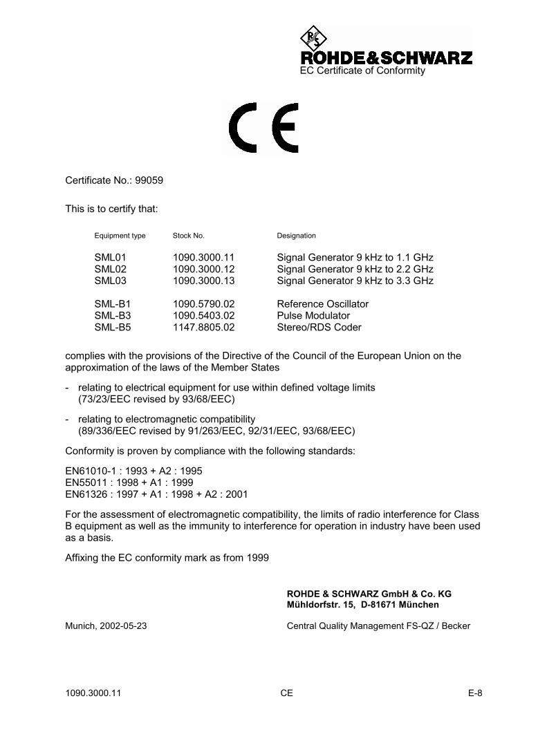
1090.3000.11 CE E-8
EC Certificate of Conformity
Certificate No.: 99059
This is to certify that:
Equipment type Stock No. Designation
SML01 1090.3000.11 Signal Generator 9 kHz to 1.1 GHz SML02 1090.3000.12 Signal Generator 9 kHz to 2.2 GHz SML03 1090.3000.13 Signal Generator 9 kHz to 3.3 GHz SML-B1 1090.5790.02 Reference Oscillator SML-B3 1090.5403.02 Pulse Modulator SML-B5 1147.8805.02 Stereo/RDS Coder
complies with the provisions of the Directive of the Council of the European Union on the approximation of the laws of the Member States - relating to electrical equipment for use within defined voltage limits
(73/23/EEC revised by 93/68/EEC) - relating to electromagnetic compatibility
(89/336/EEC revised by 91/263/EEC, 92/31/EEC, 93/68/EEC) Conformity is proven by compliance with the following standards: EN61010-1 : 1993 + A2 : 1995 EN55011 : 1998 + A1 : 1999 EN61326 : 1997 + A1 : 1998 + A2 : 2001 For the assessment of electromagnetic compatibility, the limits of radio interference for Class B equipment as well as the immunity to interference for operation in industry have been used as a basis. Affixing the EC conformity mark as from 1999
ROHDE & SCHWARZ GmbH & Co. KG Mühldorfstr. 15, D-81671 München
Munich, 2002-05-23 Central Quality Management FS-QZ / Becker

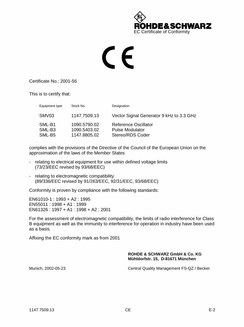
1147.7509.13 CE E-2
EC Certificate of Conformity
Certificate No.: 2001-56
This is to certify that:
Equipment type Stock No. Designation
SMV03 1147.7509.13 Vector Signal Generator 9 kHz to 3.3 GHz
SML-B1 1090.5790.02 Reference OscillatorSML-B3 1090.5403.02 Pulse ModulatorSML-B5 1147.8805.02 Stereo/RDS Coder
complies with the provisions of the Directive of the Council of the European Union on theapproximation of the laws of the Member States
- relating to electrical equipment for use within defined voltage limits(73/23/EEC revised by 93/68/EEC)
- relating to electromagnetic compatibility(89/336/EEC revised by 91/263/EEC, 92/31/EEC, 93/68/EEC)
Conformity is proven by compliance with the following standards:
EN61010-1 : 1993 + A2 : 1995EN55011 : 1998 + A1 : 1999EN61326 : 1997 + A1 : 1998 + A2 : 2001
For the assessment of electromagnetic compatibility, the limits of radio interference for ClassB equipment as well as the immunity to interference for operation in industry have been usedas a basis.
Affixing the EC conformity mark as from 2001
ROHDE & SCHWARZ GmbH & Co. KGMühldorfstr. 15, D-81671 München
Munich, 2002-05-23 Central Quality Management FS-QZ / Becker


1171.0200.29-01.00
Customer Support Technical support where and when you need it For quick, expert help with any Rohde & Schwarz equipment, contact one of our Customer Support Centers. A team of highly qualified engineers provides telephone support and will work with you to find a solution to your query on any aspect of the operation, programming or applications of Rohde & Schwarz equipment. Up-to-date information and upgrades To keep your Rohde & Schwarz equipment always up-to-date, please subscribe to our electronic newsletter at http://www.rohde-schwarz.com/www/response.nsf/newsletterpreselection or request the desired information and upgrades via email from your Customer Support Center (addresses see below). Feedback We want to know if we are meeting your support needs. If you have any comments please email us and let us know [email protected]. USA & Canada Monday to Friday (except US public holidays)
8:00 AM 8:00 PM Eastern Standard Time (EST) Tel. from USA 888-test-rsa (888-837-8772) (opt 2)
From outside USA +1 410 910 7800 (opt 2) Fax +1 410 910 7801
E-mail [email protected] East Asia Monday to Friday (except Singaporean public holidays)
8:30 AM 6:00 PM Singapore Time (SGT) Tel. +65 6 513 0488
Fax +65 6 846 1090
E-mail [email protected] Rest of the World Monday to Friday (except German public holidays)
08:00 17:00 Central European Time (CET) Tel. from Europe +49 (0) 180 512 42 42
From outside Europe +49 89 4129 13776 Fax +49 (0) 89 41 29 637 78
E-mail [email protected]

1171.0200.42-02.00
12
12Address List
Headquarters, Plants and Subsidiaries
HeadquartersROHDE&SCHWARZ GmbH & Co. KGMühldorfstraße 15 · D-81671 MünchenP.O.Box 80 14 69 · D-81614 München
PlantsROHDE&SCHWARZ Messgerätebau GmbHRiedbachstraße 58 · D-87700 MemmingenP.O.Box 16 52 · D-87686 Memmingen
ROHDE&SCHWARZ GmbH & Co. KGWerk TeisnachKaikenrieder Straße 27 · D-94244 TeisnachP.O.Box 11 49 · D-94240 Teisnach
ROHDE&SCHWARZ závodVimperk, s.r.o.Location Spidrova 49CZ-38501 Vimperk
ROHDE&SCHWARZ GmbH & Co. KGDienstleistungszentrum KölnGraf-Zeppelin-Straße 18 · D-51147 KölnP.O.Box 98 02 60 · D-51130 Köln
SubsidiariesR&S BICK Mobilfunk GmbH Fritz-Hahne-Str. 7 · D-31848 Bad Münder P.O.Box 20 02 · D-31844 Bad Münder
ROHDE&SCHWARZ FTK GmbH Wendenschloßstraße 168, Haus 28 D-12557 Berlin
ROHDE&SCHWARZ SIT GmbHAm Studio 3D-12489 Berlin
R&S Systems GmbHGraf-Zeppelin-Straße 18D-51147 Köln
GEDIS GmbHSophienblatt 100D-24114 Kiel
HAMEG Instruments GmbHIndustriestraße 6D-63533 Mainhausen
Locations Worldwide
Please refer to our homepage: www.rohde-schwarz.com
Sales Locations Service Locations National Websites
Phone +49 (89) 41 29-0Fax +49 (89) 41 29-121 64
Phone +49 (83 31) 1 08-0+49 (83 31) 1 08-1124
Phone +49 (99 23) 8 50-0Fax +49 (99 23) 8 50-174
Phone +420 (388) 45 21 09Fax +420 (388) 45 21 13
Phone +49 (22 03) 49-0Fax +49 (22 03) 49 51-229
[email protected]@rohde-schwarz.com
Phone +49 (50 42) 9 98-0Fax +49 (50 42) 9 98-105
Phone +49 (30) 658 91-122Fax +49 (30) 655 50-221
Phone +49 (30) 658 84-0Fax +49 (30) 658 84-183
Phone +49 (22 03) 49-5 23 25Fax +49 (22 03) 49-5 23 36
Phone +49 (431) 600 51-0Fax +49 (431) 600 [email protected]
Phone +49 (61 82) 800-0Fax +49 (61 82) 800-100

R&S®SML / R&S®SMV03 General Overview of Manuals
1090.3123.12 E E-6
General Overview of Manuals
Operating Manual for Signal Generator R&S SML / R&S SMV03 This operating manual provides you with all the information necessary for putting into operation, manual and remote control as well as maintaining of Signal Generator R&S SML / R&S SMV03 and also contains specifications of the instrument and available options. The following models are described in this manual:
R&S SML01 9 kHz to 1.1 GHz R&S SML02 9 kHz to 2.2 GHz R&S SML03 9 kHz to 3.3 GHz R&S SMV03 9 kHz to 3.3 GHz
The contents of the chapters are as follows: Data sheet informs you about specifications relating to functions and characteristics of the
instrument and its options.
Chapter 1 contains all information about putting into operation (unpacking, connection to AC supply, switching on and off), functional testing and installation of the instrument, preset settings and views of the front and rear panel showing the controls and connectors needed for operation.
Chapter 2 presents a brief introduction and typical settings to users working with the R&S SML / R&S SMV03 for the first time.
Chapter 3 describes manual control of the signal generator, for example calling up of menus, selection and editing of parameters, use of the list editor and the SAVE/RECALL function. This chapter also contains an overview of menus showing the functions available for the instruments and its options.
Chapter 4 describes the functions of the instrument and its options which can be activated manually via menus or by remote control (frequency and level settings, analog modulations, sweep and general functions not directly related to signal generation).
Chapter 5 provides basic information on remote control, for example on the IEC/IEEE bus, RS-232-C interface, interface and device messages, command processing, status reporting system, etc.
Chapter 6 contains for each command system an overview and description of all commands available for the instrument and its options as well as an alphabetical list of all commands.
Chapter 7 includes programming examples for remote control.
Chapter 8 gives information on preventive maintenance, for example for keeping the exterior clean, storage, etc.
Chapter 9 contains the SCPI-specific and device-specific error messages displayed on the instrument.
Chapter 10 includes the performance test with the performance test report.

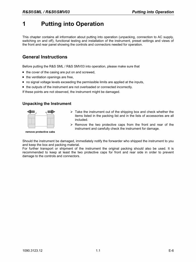
R&S®SML / R&S®SMV03 Putting into Operation
1090.3123.12 E-6 1.1
1 Putting into Operation
This chapter contains all information about putting into operation (unpacking, connection to AC supply, switching on and off), functional testing and installation of the instrument, preset settings and views of the front and rear panel showing the controls and connectors needed for operation.
General Instructions
Before putting the R&S SML / R&S SMV03 into operation, please make sure that
• the cover of the casing are put on and screwed, • the ventilation openings are free, • no signal voltage levels exceeding the permissible limits are applied at the inputs, • the outputs of the instrument are not overloaded or connected incorrectly. If these points are not observed, the instrument might be damaged.
Unpacking the Instrument
remove protective cabs
Take the instrument out of the shipping box and check whether the items listed in the packing list and in the lists of accessories are all included.
Remove the two protective caps from the front and rear of the instrument and carefully check the instrument for damage.
Should the instrument be damaged, immediately notify the forwarder who shipped the instrument to you and keep the box and packing material. For further transport or shipment of the instrument the original packing should also be used. It is recommended to keep at least the two protective caps for front and rear side in order to prevent damage to the controls and connectors.
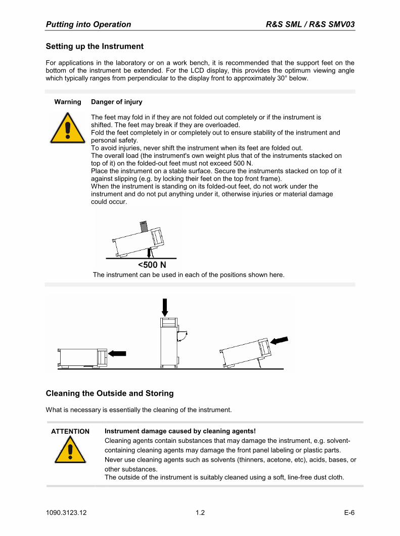
Putting into Operation R&S SML / R&S SMV03
1090.3123.12 E-6 1.2
Setting up the Instrument
For applications in the laboratory or on a work bench, it is recommended that the support feet on the bottom of the instrument be extended. For the LCD display, this provides the optimum viewing angle which typically ranges from perpendicular to the display front to approximately 30° below.
Warning Danger of injury The feet may fold in if they are not folded out completely or if the instrument is shifted. The feet may break if they are overloaded. Fold the feet completely in or completely out to ensure stability of the instrument and personal safety. To avoid injuries, never shift the instrument when its feet are folded out. The overall load (the instrument's own weight plus that of the instruments stacked on top of it) on the folded-out feet must not exceed 500 N. Place the instrument on a stable surface. Secure the instruments stacked on top of it against slipping (e.g. by locking their feet on the top front frame). When the instrument is standing on its folded-out feet, do not work under the instrument and do not put anything under it, otherwise injuries or material damage could occur.
The instrument can be used in each of the positions shown here.
Cleaning the Outside and Storing
What is necessary is essentially the cleaning of the instrument.
ATTENTION Instrument damage caused by cleaning agents! Cleaning agents contain substances that may damage the instrument, e.g. solvent-containing cleaning agents may damage the front panel labeling or plastic parts. Never use cleaning agents such as solvents (thinners, acetone, etc), acids, bases, or other substances. The outside of the instrument is suitably cleaned using a soft, line-free dust cloth.
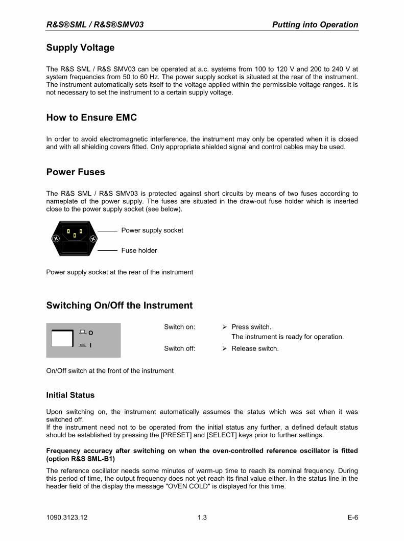
R&S®SML / R&S®SMV03 Putting into Operation
1090.3123.12 E-6 1.3
Supply Voltage
The R&S SML / R&S SMV03 can be operated at a.c. systems from 100 to 120 V and 200 to 240 V at system frequencies from 50 to 60 Hz. The power supply socket is situated at the rear of the instrument. The instrument automatically sets itself to the voltage applied within the permissible voltage ranges. It is not necessary to set the instrument to a certain supply voltage.
How to Ensure EMC
In order to avoid electromagnetic interference, the instrument may only be operated when it is closed and with all shielding covers fitted. Only appropriate shielded signal and control cables may be used.
Power Fuses
The R&S SML / R&S SMV03 is protected against short circuits by means of two fuses according to nameplate of the power supply. The fuses are situated in the draw-out fuse holder which is inserted close to the power supply socket (see below).
Power supply socket
Fuse holder
Power supply socket at the rear of the instrument
Switching On/Off the Instrument
O
I
Switch on: Press switch. The instrument is ready for operation.
Switch off: Release switch.
On/Off switch at the front of the instrument
Initial Status
Upon switching on, the instrument automatically assumes the status which was set when it was switched off. If the instrument need not to be operated from the initial status any further, a defined default status should be established by pressing the [PRESET] and [SELECT] keys prior to further settings. Frequency accuracy after switching on when the oven-controlled reference oscillator is fitted (option R&S SML-B1)
The reference oscillator needs some minutes of warm-up time to reach its nominal frequency. During this period of time, the output frequency does not yet reach its final value either. In the status line in the header field of the display the message "OVEN COLD" is displayed for this time.
Putting into Operation R&S SML / R&S SMV03
1090.3123.12 E-6 1.4
RAM With Battery Back-Up
The R&S SML / R&S SMV03 has a static read-write memory (CMOS-RAM) with battery back-up, in which 50 different complete settings of the instrument can be stored (cf. Chapter 3, section "Storing and Calling of Instrument Settings"). In addition, all data and/or lists the user enters himself, such as for user correction of the level, are stored in the RAM. Further, all data of the calibrations running within the instrument in the R&S SML / R&S SMV03 are stored in the RAM (cf. Chapter 4, section "Calibration"). A lithium battery with a service life of approx. 5 years serves to supply the RAM with power. When the battery is discharged, the data stored will be lost. Exchanging the battery is described in the Service Manual.
Preset Setting
A defined setting status is achieved by pressing the [PRESET] key. Preset Status: RF frequency 100 MHz RF level -10 dBm Reference frequency internal, adjustment off Offsets 0 Modulations switched off Transient-free level setting switched off, level attenuator mode: Auto Internal level control level Alc: On User correction level Ucor: Off LF output switched off Sweep switched off Suppression of indications system security: unaltered Protection of calibration data protection lock: unaltered Settings stored unaltered Data, lists etc. stored unaltered IEC-bus address unaltered All parameters and circuit states, even those of operating modes which are not activated, are preset by means of Preset. The presettings going beyond the above list can be seen from the menu representations as of Chapter 4 which each indicate the Preset setting status. Functional Test
On switching on the instrument and permanently during operation, the R&S SML / R&S SMV03 carries out a self test. The ROM contents as well as the battery of the non-volatile RAM are checked. The most important instrument functions are automatically monitored during operation. If an error is detected, the message "Err" is displayed in the status line. For further identification of the error, press the [ERROR] key. Thereupon a description of the error is displayed (cf. Chapter 9, section "Error Messages"). Return to the menu exited by pressing the [BACK] key. If required, internal test points can be polled by the user and the results be read out and displayed, cf. Service Manual.
Mounting into a 19" Rack
The R&S SML / R&S SMV03 can be mounted into a 19" rack by means of rack adapter ZZA-211 (stock no. 1096.3260.00). The mounting instructions are attached to the adapter.
ATTENTION Risk of damage to the instrument. Ensure free air inlet at the perforation of the side walls and air outlet at the rear of the instrument in rack mounting. Non-observance may cause damage to the instrument.
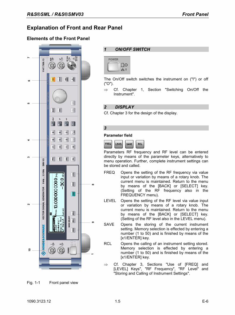
R&S®SML / R&S®SMV03 Front Panel
1090.3123.12 E-6 1.5
Explanation of Front and Rear Panel
Elements of the Front Panel
3
MOD LF
RF
50
I Q
1147
.750
9.13
dBµV µV mV
VEC
TOR
SIG
NA
LG
ENER
ATO
R9
kHz.
..3.3
GHz
SMV
03.
.
MAX
25W
REF
PWR
ASSI
GNPR
ESET
LOCA
LER
ROR
LEVE
L
FREQ
SAVE
RCL
BACK
SELE
CTHE
LP
STAT
US
MOD
ON/O
FF
RFME
NU1
012
3
45
6
78
9
.-
.
G M kmn
x1µ
ENTE
RME
NU2
ON/O
FF
102
45
67
19
8
3
1 ON/OFF SWITCH
The On/Off switch switches the instrument on ("I") or off ("O"). ⇒ Cf. Chapter 1, Section "Switching On/Off the
Instrument".
2 DISPLAY Cf. Chapter 3 for the design of the display.
3Parameter field
Parameters RF frequency and RF level can be entered directly by means of the parameter keys, alternatively to menu operation. Further, complete instrument settings can be stored and called.
FREQ Opens the setting of the RF frequency via value input or variation by means of a rotary knob. The current menu is maintained. Return to the menu by means of the [BACK] or [SELECT] key. (Setting of the RF frequency also in the FREQUENCY menu).
LEVEL Opens the setting of the RF level via value input or variation by means of a rotary knob. The current menu is maintained. Return to the menu by means of the [BACK] or [SELECT] key. (Setting of the RF level also in the LEVEL menu).
SAVE Opens the storing of the current instrument setting. Memory selection is effected by entering a number (1 to 50) and is finished by means of the [x1/ENTER] key.
RCL Opens the calling of an instrument setting stored. Memory selection is effected by entering a number (1 to 50) and is finished by means of the [x1/ENTER] key.
⇒ Cf. Chapter 3, Sections "Use of [FREQ] and [LEVEL] Keys", "RF Frequency", "RF Level" and "Storing and Calling of Instrument Settings".
Fig. 1-1 Front panel view
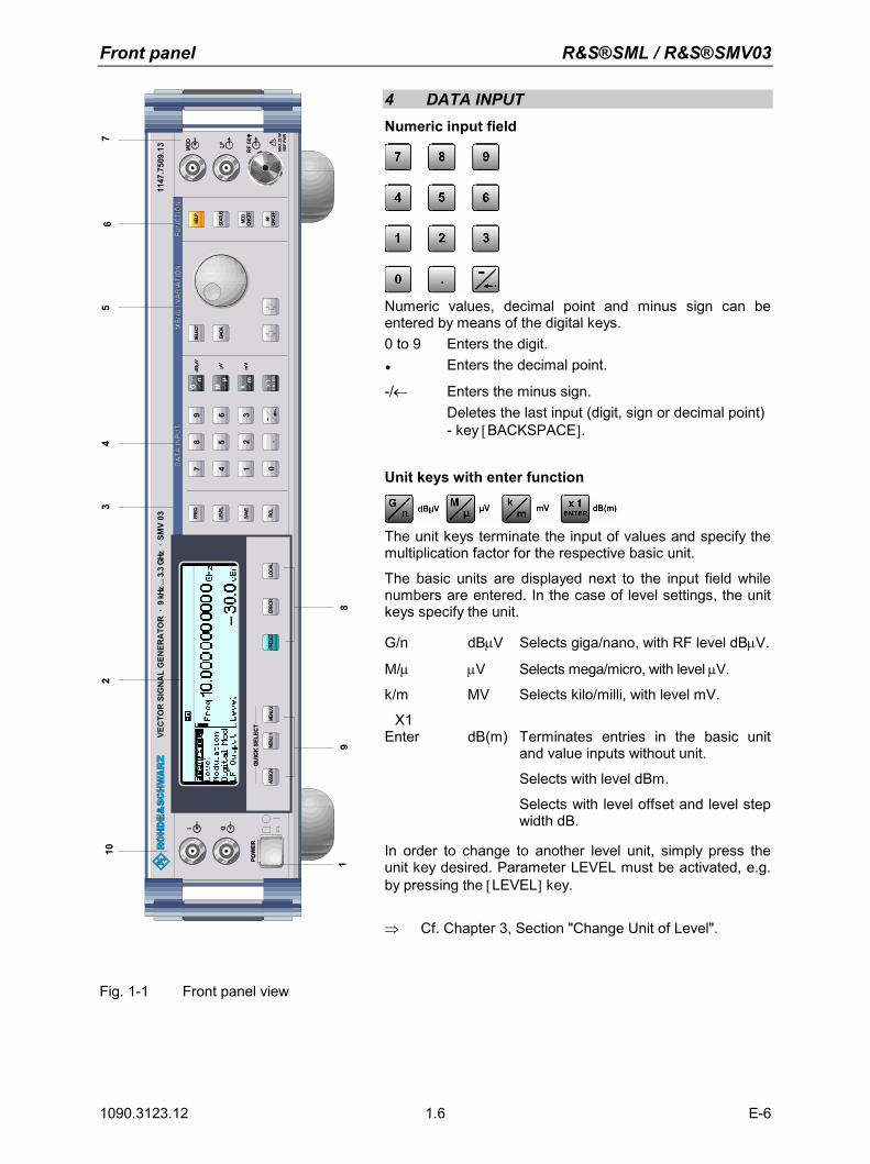
Front panel R&S®SML / R&S®SMV03
1090.3123.12 E-6 1.6
3
MOD LF
RF
50
I Q
1147
.750
9.13
dBµV µV mV
VEC
TOR
SIG
NA
LG
ENER
ATO
R9
kHz.
..3.3
GHz
SMV
03.
.
MAX
25W
REF
PWR
ASSI
GNPR
ESET
LOCA
LER
ROR
LEVE
L
FREQ
SAVE
RCL
BACK
SELE
CTHE
LP
STAT
US
MOD
ON/O
FF
RFME
NU1
012
3
45
6
78
9
.-
.
G M kmn
x1µ
ENTE
RME
NU2
ON/O
FF
102
45
67
19
8
34 DATA INPUT Numeric input field
Numeric values, decimal point and minus sign can be entered by means of the digital keys. 0 to 9 Enters the digit. Enters the decimal point.
-/← Enters the minus sign. Deletes the last input (digit, sign or decimal point)
- key [BACKSPACE].
Unit keys with enter function
The unit keys terminate the input of values and specify the multiplication factor for the respective basic unit.
The basic units are displayed next to the input field while numbers are entered. In the case of level settings, the unit keys specify the unit.
G/n dBµV Selects giga/nano, with RF level dBµV.
M/µ µV Selects mega/micro, with level µV.
k/m MV Selects kilo/milli, with level mV.
X1 Enter dB(m) Terminates entries in the basic unit
and value inputs without unit.
Selects with level dBm.
Selects with level offset and level step width dB.
In order to change to another level unit, simply press the unit key desired. Parameter LEVEL must be activated, e.g. by pressing the [LEVEL] key. ⇒ Cf. Chapter 3, Section "Change Unit of Level".
Fig. 1-1 Front panel view
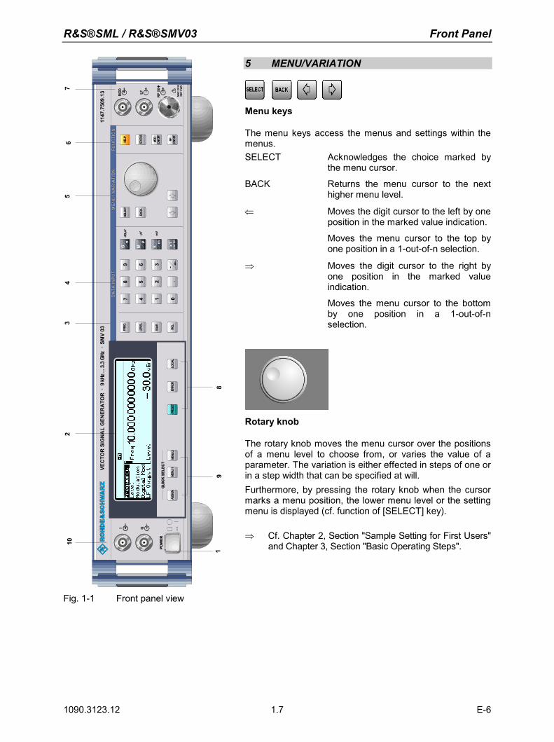
R&S®SML / R&S®SMV03 Front Panel
1090.3123.12 E-6 1.7
3
MOD LF
RF
50
I Q
1147
.750
9.13
dBµV µV mV
VEC
TOR
SIG
NA
LG
ENER
ATO
R9
kHz.
..3.3
GHz
SMV
03.
.
MAX
25W
REF
PWR
ASSI
GNPR
ESET
LOCA
LER
ROR
LEVE
L
FREQ
SAVE
RCL
BACK
SELE
CTHE
LP
STAT
US
MOD
ON/O
FF
RFME
NU1
012
3
45
6
78
9
.-
.
G M kmn
x1µ
ENTE
RME
NU2
ON/O
FF
102
45
67
19
8
35 MENU/VARIATION
Menu keys
The menu keys access the menus and settings within the menus. SELECT Acknowledges the choice marked by
the menu cursor.
BACK Returns the menu cursor to the next higher menu level.
⇐ Moves the digit cursor to the left by one position in the marked value indication.
Moves the menu cursor to the top by one position in a 1-out-of-n selection.
⇒ Moves the digit cursor to the right by one position in the marked value indication.
Moves the menu cursor to the bottom by one position in a 1-out-of-n selection.
Rotary knob
The rotary knob moves the menu cursor over the positions of a menu level to choose from, or varies the value of a parameter. The variation is either effected in steps of one or in a step width that can be specified at will. Furthermore, by pressing the rotary knob when the cursor marks a menu position, the lower menu level or the setting menu is displayed (cf. function of [SELECT] key). ⇒ Cf. Chapter 2, Section "Sample Setting for First Users"
and Chapter 3, Section "Basic Operating Steps".
Fig. 1-1 Front panel view
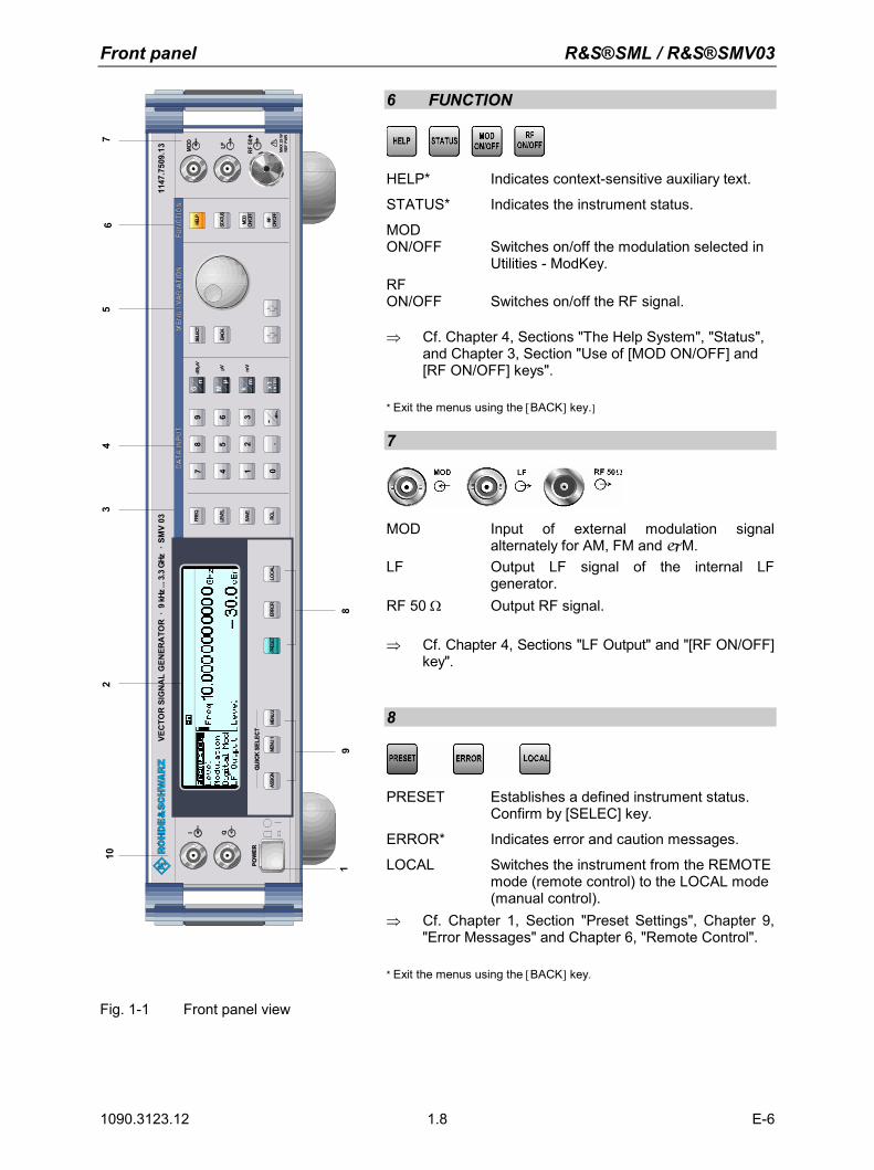
Front panel R&S®SML / R&S®SMV03
1090.3123.12 E-6 1.8
3
MOD LF
RF
50
I Q
1147
.750
9.13
dBµV µV mV
VEC
TOR
SIG
NA
LG
ENER
ATO
R9
kHz.
..3.3
GHz
SMV
03.
.
MAX
25W
REF
PWR
ASSI
GNPR
ESET
LOCA
LER
ROR
LEVE
L
FREQ
SAVE
RCL
BACK
SELE
CTHE
LP
STAT
US
MOD
ON/O
FF
RFME
NU1
012
3
45
6
78
9
.-
.
G M kmn
x1µ
ENTE
RME
NU2
ON/O
FF
102
45
67
19
8
36 FUNCTION
HELP* Indicates context-sensitive auxiliary text.
STATUS* Indicates the instrument status.
MOD ON/OFF Switches on/off the modulation selected in
Utilities - ModKey. RF ON/OFF Switches on/off the RF signal. ⇒ Cf. Chapter 4, Sections "The Help System", "Status",
and Chapter 3, Section "Use of [MOD ON/OFF] and [RF ON/OFF] keys".
* Exit the menus using the [BACK] key.]
7
MOD Input of external modulation signal alternately for AM, FM and M.
LF Output LF signal of the internal LF generator.
RF 50 Ω Output RF signal. ⇒ Cf. Chapter 4, Sections "LF Output" and "[RF ON/OFF]
key".
8
PRESET Establishes a defined instrument status. Confirm by [SELEC] key.
ERROR* Indicates error and caution messages.
LOCAL Switches the instrument from the REMOTE mode (remote control) to the LOCAL mode (manual control).
⇒ Cf. Chapter 1, Section "Preset Settings", Chapter 9, "Error Messages" and Chapter 6, "Remote Control".
* Exit the menus using the [BACK] key.
Fig. 1-1 Front panel view
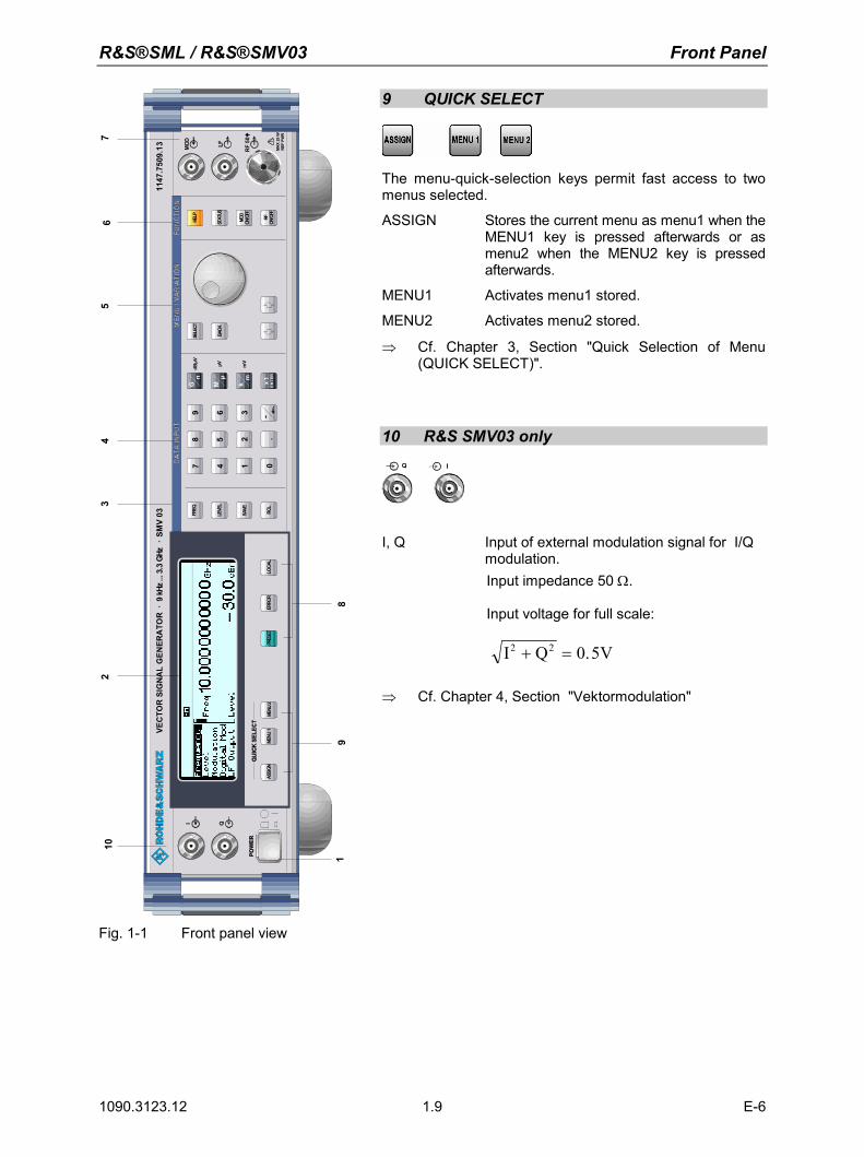
R&S®SML / R&S®SMV03 Front Panel
1090.3123.12 E-6 1.9
3
MOD LF
RF
50
I Q
1147
.750
9.13
dBµV µV mV
VEC
TOR
SIG
NA
LG
ENER
ATO
R9
kHz.
..3.3
GHz
SMV
03.
.
MAX
25W
REF
PWR
ASSI
GNPR
ESET
LOCA
LER
ROR
LEVE
L
FREQ
SAVE
RCL
BACK
SELE
CTHE
LP
STAT
US
MOD
ON/O
FF
RFME
NU1
012
3
45
6
78
9
.-
.
G M kmn
x1µ
ENTE
RME
NU2
ON/O
FF
102
45
67
19
8
39 QUICK SELECT
The menu-quick-selection keys permit fast access to two menus selected.
ASSIGN Stores the current menu as menu1 when the MENU1 key is pressed afterwards or as menu2 when the MENU2 key is pressed afterwards.
MENU1 Activates menu1 stored.
MENU2 Activates menu2 stored.
⇒ Cf. Chapter 3, Section "Quick Selection of Menu (QUICK SELECT)".
10 R&S SMV03 only
Q I
I, Q Input of external modulation signal for I/Q modulation.
Input impedance 50 Ω.
Input voltage for full scale:
I Q V2 2 0 5+ = .
⇒ Cf. Chapter 4, Section "Vektormodulation"
Fig. 1-1 Front panel view
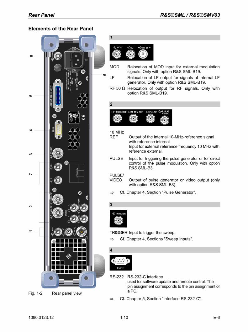
Rear Panel R&S®SML / R&S®SMV03
1090.3123.12 E-6 1.10
Elements of the Rear Panel
MO
D
LF
10M
Hz
REF
10M
Hz
REF
TRIG
GER
RS23
2IE
EE48
862
5SC
PI
RF50
LRST
EREO
F1/
F2:
IEC
127
-T
2.5
H/
250
V
AUT
OM
ATI
CPO
WER
SELE
CTI
ON
200
VA
200
...24
0V
50...
60H
z50
...40
0H
z10
0...
120
V
LR11
4196 C
® US
OPT
ION
INC
L.
S/P
DIF
PULS
EPU
LSE
/VI
DEO
IQ
12
54
37
6
8
Fig. 1-2 Rear panel view
1
MOD LF RF 50
MOD Relocation of MOD input for external modulation signals. Only with option R&S SML-B19.
LF Relocation of LF output for signals of internal LF generator. Only with option R&S SML-B19.
RF 50 Ω Relocation of output for RF signals. Only with option R&S SML-B19.
2
10 MHz REF PULSE PULSE VIDEO 10 MHz REF
10 MHz REF Output of the internal 10-MHz-reference signal
with reference internal. Input for external reference frequency 10 MHz with reference external.
PULSE Input for triggering the pulse generator or for direct control of the pulse modulation. Only with option R&S SML-B3.
PULSE/ VIDEO Output of pulse generator or video output (only
with option R&S SML-B3).
⇒ Cf. Chapter 4, Section "Pulse Generator". 3
TRIGGER
TRIGGER Input to trigger the sweep. ⇒ Cf. Chapter 4, Sections "Sweep Inputs". 4
RS-232 RS-232-C interface used for software update and remote control. The pin assignment corresponds to the pin assignment of a PC.
⇒ Cf. Chapter 5, Section "Interface RS-232-C".
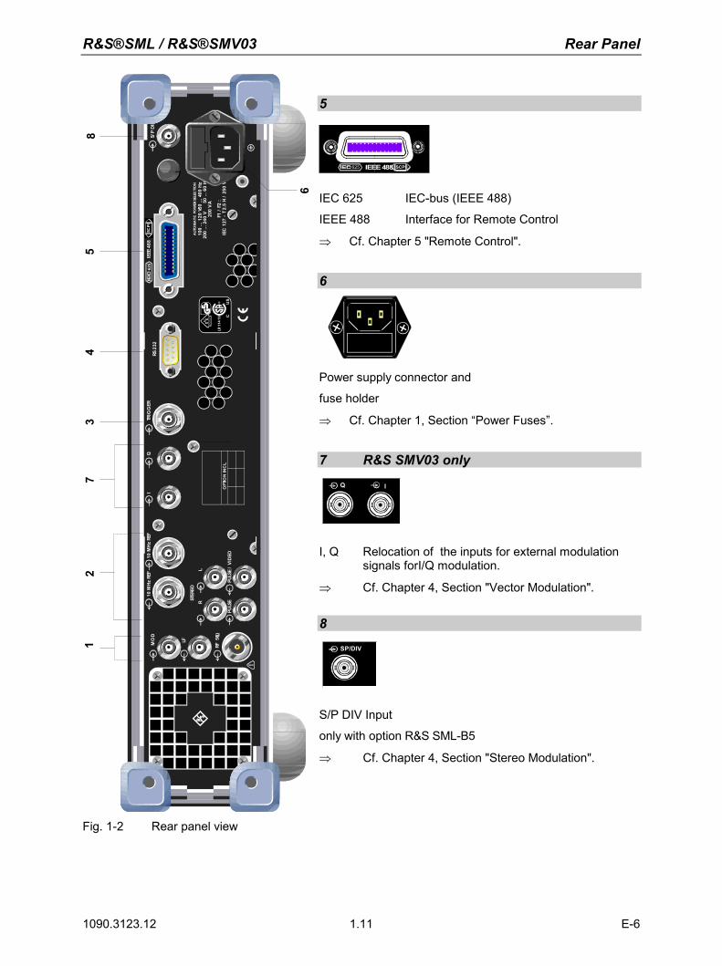
R&S®SML / R&S®SMV03 Rear Panel
1090.3123.12 E-6 1.11
MO
D
LF
10M
Hz
REF
10M
Hz
REF
TRIG
GER
RS23
2IE
EE48
862
5SC
PI
RF50
LRST
EREO
F1/
F2:
IEC
127
-T
2.5
H/
250
V
AUT
OM
ATI
CPO
WER
SELE
CTI
ON
200
VA
200
...24
0V
50...
60H
z50
...40
0H
z10
0...
120
V
LR11
4196 C
® US
OPT
ION
INC
L.
S/P
DIF
PULS
EPU
LSE
/VI
DEO
IQ
12
54
37
6
8
Fig. 1-2 Rear panel view
5
SCPI625 IEEE 488
IEC 625 IEC-bus (IEEE 488)
IEEE 488 Interface for Remote Control
⇒ Cf. Chapter 5 "Remote Control".
6
Power supply connector and
fuse holder
⇒ Cf. Chapter 1, Section “Power Fuses”.
7 R&S SMV03 only
Q I
I, Q Relocation of the inputs for external modulation signals forI/Q modulation.
⇒ Cf. Chapter 4, Section "Vector Modulation". 8
SP/DIV
S/P DIV Input
only with option R&S SML-B5
⇒ Cf. Chapter 4, Section "Stereo Modulation".

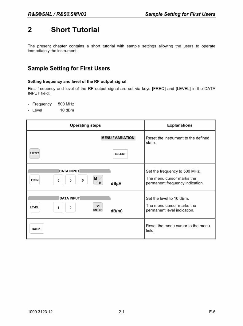
R&S®SML / R&S®SMV03 Sample Setting for First Users
1090.3123.12 E-6 2.1
2 Short Tutorial
The present chapter contains a short tutorial with sample settings allowing the users to operate immediately the instrument.
Sample Setting for First Users
Setting frequency and level of the RF output signal
First frequency and level of the RF output signal are set via keys [FREQ] and [LEVEL] in the DATA INPUT field: - Frequency 500 MHz - Level 10 dBm
Operating steps Explanations
PRESET
SELECT
MENU / VARIATION
Reset the instrument to the defined state.
0 05FREQ Mµ
DATA INPUT
dBµV
Set the frequency to 500 MHz.
The menu cursor marks the permanent frequency indication.
01LEVEL
DATA INPUT
x1ENTER dB(m)
Set the level to 10 dBm.
The menu cursor marks the permanent level indication.
BACK
Reset the menu cursor to the menu field.
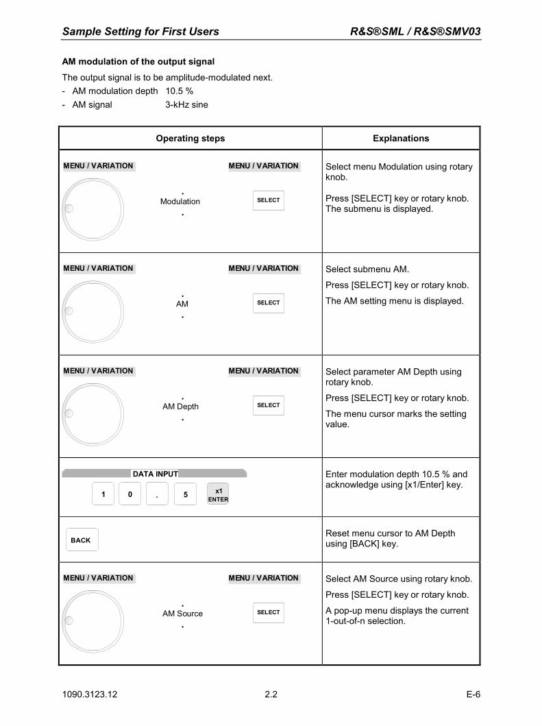
Sample Setting for First Users R&S®SML / R&S®SMV03
1090.3123.12 E-6 2.2
AM modulation of the output signal
The output signal is to be amplitude-modulated next. - AM modulation depth 10.5 % - AM signal 3-kHz sine
Operating steps Explanations
.Modulation
.
MENU / VARIATION
SELECT
MENU / VARIATION
Select menu Modulation using rotary knob.
Press [SELECT] key or rotary knob. The submenu is displayed.
.AM .
MENU / VARIATION
SELECT
MENU / VARIATION
Select submenu AM.
Press [SELECT] key or rotary knob.
The AM setting menu is displayed.
.AM Depth
.
MENU / VARIATION
SELECT
MENU / VARIATION
Select parameter AM Depth using rotary knob.
Press [SELECT] key or rotary knob.
The menu cursor marks the setting value.
DATA INPUT
x1ENTER
1 0 5.
Enter modulation depth 10.5 % and acknowledge using [x1/Enter] key.
BACK
Reset menu cursor to AM Depth using [BACK] key.
.AM Source
.
MENU / VARIATION
SELECT
MENU / VARIATION
Select AM Source using rotary knob.
Press [SELECT] key or rotary knob.
A pop-up menu displays the current 1-out-of-n selection.
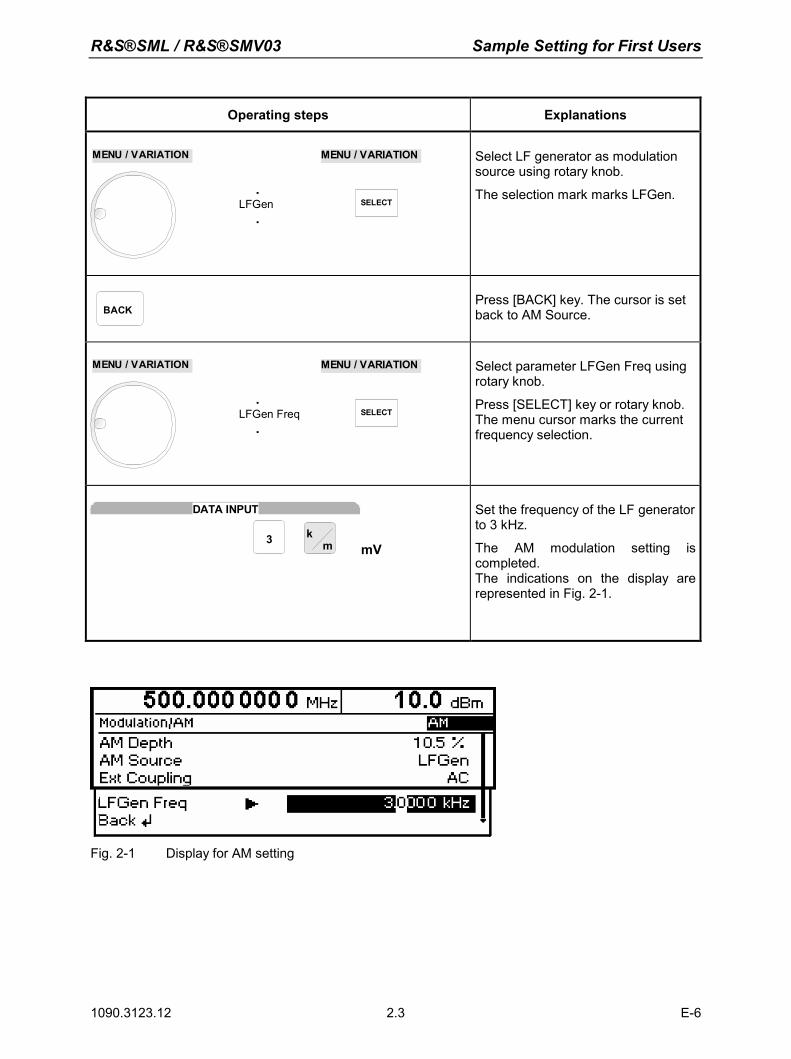
R&S®SML / R&S®SMV03 Sample Setting for First Users
1090.3123.12 E-6 2.3
Operating steps Explanations
.LFGen
.
MENU / VARIATION
SELECT
MENU / VARIATION
Select LF generator as modulation source using rotary knob.
The selection mark marks LFGen.
BACK
Press [BACK] key. The cursor is set back to AM Source.
.LFGen Freq
.
MENU / VARIATION
SELECT
MENU / VARIATION
Select parameter LFGen Freq using rotary knob.
Press [SELECT] key or rotary knob. The menu cursor marks the current frequency selection.
3 km
DATA INPUT
mV
Set the frequency of the LF generator to 3 kHz.
The AM modulation setting is completed. The indications on the display are represented in Fig. 2-1.
Fig. 2-1 Display for AM setting
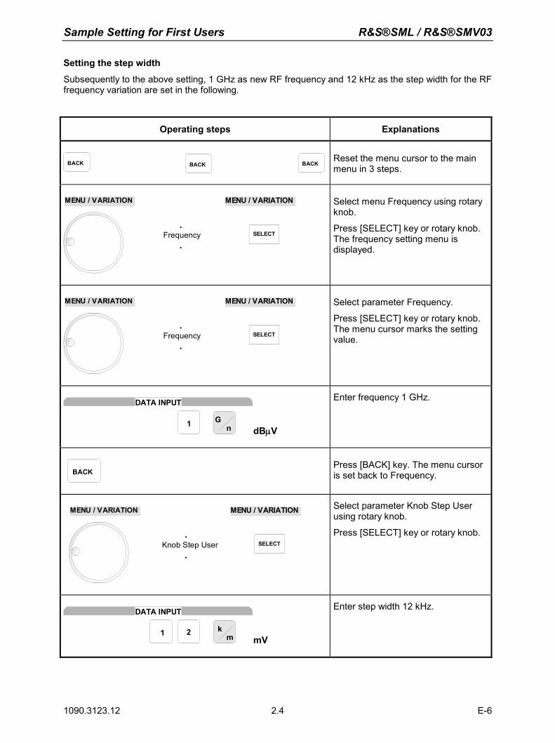
Sample Setting for First Users R&S®SML / R&S®SMV03
1090.3123.12 E-6 2.4
Setting the step width
Subsequently to the above setting, 1 GHz as new RF frequency and 12 kHz as the step width for the RF frequency variation are set in the following.
Operating steps Explanations
BACK BACK BACKReset the menu cursor to the main menu in 3 steps.
.Frequency
.
MENU / VARIATION
SELECT
MENU / VARIATION
Select menu Frequency using rotary knob.
Press [SELECT] key or rotary knob. The frequency setting menu is displayed.
.Frequency
.
MENU / VARIATION
SELECT
MENU / VARIATION
Select parameter Frequency.
Press [SELECT] key or rotary knob. The menu cursor marks the setting value.
1 Gn
DATA INPUT
dBµV
Enter frequency 1 GHz.
BACK
Press [BACK] key. The menu cursor is set back to Frequency.
.Knob Step User
.
MENU / VARIATION
SELECT
MENU / VARIATION
Select parameter Knob Step User using rotary knob.
Press [SELECT] key or rotary knob.
21 km
DATA INPUT
mV
Enter step width 12 kHz.
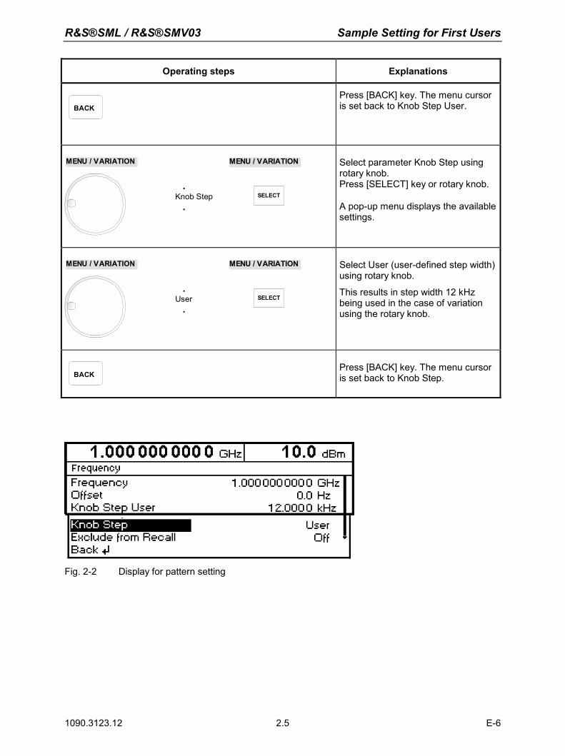
R&S®SML / R&S®SMV03 Sample Setting for First Users
1090.3123.12 E-6 2.5
Operating steps Explanations
BACK
Press [BACK] key. The menu cursor is set back to Knob Step User.
.Knob Step
.
MENU / VARIATION
SELECT
MENU / VARIATION
Select parameter Knob Step using rotary knob. Press [SELECT] key or rotary knob.
A pop-up menu displays the available settings.
.User
.
MENU / VARIATION
SELECT
MENU / VARIATION
Select User (user-defined step width) using rotary knob.
This results in step width 12 kHz being used in the case of variation using the rotary knob.
BACK
Press [BACK] key. The menu cursor is set back to Knob Step.
Fig. 2-2 Display for pattern setting

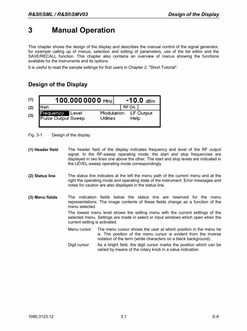
R&S®SML / R&S®SMV03 Design of the Display
1090.3123.12 E-6 3.1
3 Manual Operation
This chapter shows the design of the display and describes the manual control of the signal generator, for example calling up of menus, selection and editing of parameters, use of the list editor and the SAVE/RECALL function. This chapter also contains an overview of menus showing the functions available for the instruments and its options. It is useful to read the sample settings for first users in Chapter 2, "Short Tutorial".
Design of the Display
(1)
(2)
(3)
Fig. 3-1 Design of the display
(1) Header field The header field of the display indicates frequency and level of the RF output
signal. In the RF-sweep operating mode, the start and stop frequencies are displayed in two lines one above the other. The start and stop levels are indicated in the LEVEL-sweep operating mode correspondingly.
(2) Status line The status line indicates at the left the menu path of the current menu and at the
right the operating mode and operating state of the instrument. Error messages and notes for caution are also displayed in the status line.
(3) Menu fields The indication fields below the status line are reserved for the menu
representations. The image contents of these fields change as a function of the menu selected. The lowest menu level shows the setting menu with the current settings of the selected menu. Settings are made in select or input windows which open when the current setting is activated.
Menu cursor The menu cursor shows the user at which position in the menu he is. The position of the menu cursor is evident from the inverse notation of the term (white characters on a black background).
Digit cursor As a bright field, the digit cursor marks the position which can be varied by means of the rotary knob in a value indication.
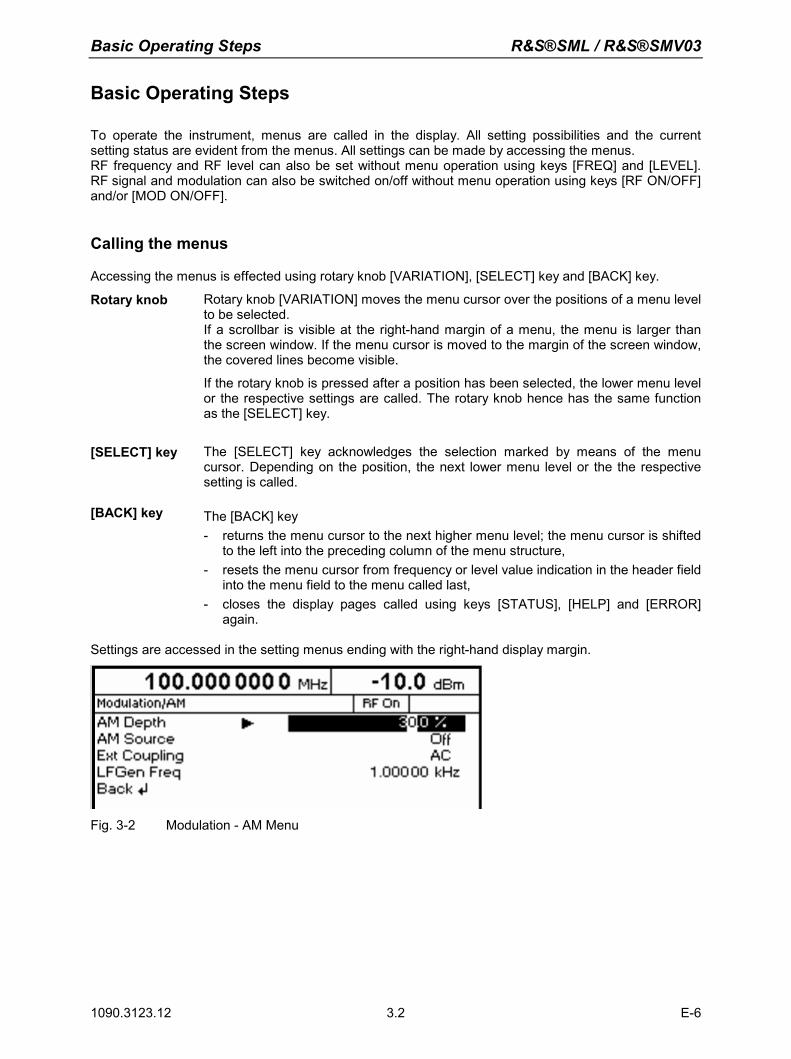
Basic Operating Steps R&S®SML / R&S®SMV03
1090.3123.12 E-6 3.2
Basic Operating Steps
To operate the instrument, menus are called in the display. All setting possibilities and the current setting status are evident from the menus. All settings can be made by accessing the menus. RF frequency and RF level can also be set without menu operation using keys [FREQ] and [LEVEL]. RF signal and modulation can also be switched on/off without menu operation using keys [RF ON/OFF] and/or [MOD ON/OFF].
Calling the menus
Accessing the menus is effected using rotary knob [VARIATION], [SELECT] key and [BACK] key.
Rotary knob Rotary knob [VARIATION] moves the menu cursor over the positions of a menu level to be selected. If a scrollbar is visible at the right-hand margin of a menu, the menu is larger than the screen window. If the menu cursor is moved to the margin of the screen window, the covered lines become visible.
If the rotary knob is pressed after a position has been selected, the lower menu level or the respective settings are called. The rotary knob hence has the same function as the [SELECT] key.
[SELECT] key The [SELECT] key acknowledges the selection marked by means of the menu cursor. Depending on the position, the next lower menu level or the the respective setting is called.
[BACK] key The [BACK] key - returns the menu cursor to the next higher menu level; the menu cursor is shifted
to the left into the preceding column of the menu structure, - resets the menu cursor from frequency or level value indication in the header field
into the menu field to the menu called last, - closes the display pages called using keys [STATUS], [HELP] and [ERROR]
again. Settings are accessed in the setting menus ending with the right-hand display margin.
Fig. 3-2 Modulation - AM Menu
R&S®SML / R&S®SMV03 Basic Operating Steps
1090.3123.12 E-6 3.3
Selection and Change of Parameters
Select parameter Set the menu cursor to the name of the parameter desired using the rotary knob, e.g. to AM Depth in the AM menu, cf. Fig. 3-2.
Change setting value
Select parameter.
Press [SELECT] key or rotary knob. The menu cursor changes from the parameter selected in the left-hand
column of the setting menu to the setting value on the right, e.g. from AM Depth to 15%, cf. Fig. 3-2.
Via value inputs Press the first digit of the new value or minus sign. The old value is deleted, the entry is indicated in the marked field.
Enter further digits.
Terminate the input using a unit key or, in the case of inputs in the base unit or in the case of inputs without unit, using the [1x/Enter] key.
Press [BACK] key.
The menu cursor wraps back to the appropriate parameter.
Using rotary knob Set the digit cursor (bright field) to the position of the setting value to be
varied using keys [] [].
Turn rotary knob. The value is varied.
Note: RF frequency and RF level can also be varied in a step width which can be defined arbitrarily, using the rotary knob. In the respective setting menu (Frequency or Level), the step width is entered as Knob Step User and the Knob Step set from Decimal to User. To point to the fact that the step width has been converted to the value programmed, the bright field as a symbol of the digit cursor disappears in the respective value indication.
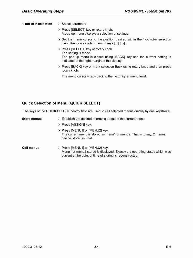
Basic Operating Steps R&S®SML / R&S®SMV03
1090.3123.12 E-6 3.4
1-out-of-n selection Select parameter.
Press [SELECT] key or rotary knob. A pop-up menu displays a selection of settings.
Set the menu cursor to the position desired within the 1-out-of-n selection using the rotary knob or cursor keys [⇐] [⇒].
Press [SELECT] key or rotary knob. The setting is made. The pop-up menu is closed using [BACK] key and the current setting is
indicated at the right margin of the display.
Press [BACK] key or mark selection Back using rotary knob and then press rotary knob.
The menu cursor wraps back to the next higher menu level.
Quick Selection of Menu (QUICK SELECT)
The keys of the QUICK SELECT control field are used to call selected menus quickly by one keystroke. Store menus Establish the desired operating status of the current menu.
Press [ASSIGN] key.
Press [MENU1] or [MENU2] key. The current menu is stored as menu1 or menu2. That is to say, 2 menus can be stored in total.
Call menus Press [MENU1] or [MENU2] key.
Menu1 or menu2 stored is displayed. Exactly the operating status which was current at the point of time of storing is reconstructed.
R&S®SML / R&S®SMV03 Basic Operating Steps
1090.3123.12 E-6 3.5
Use of [FREQ] and [LEVEL] Keys
RF frequency and RF level can be set without menu operation as well using direct keys [FREQ] and [LEVEL]. [FREQ] / [LEVEL] keys Press [FREQ] or [LEVEL] key.
The frequency or the level indication in the header field of the display is marked. The current menu at the display is maintained.
Alter the value via a value input or the rotary knob.
Press [BACK] or [SELECT] key. The menu cursor wraps to the position marked last in the menu.
Use of [RF ON/OFF] and [MOD ON/OFF]
RF signal and modulation can be switched on/off without menu operation as well using keys [RF ON/OFF] or [MOD ON/OFF] (cf. Sections "[RF ON/OFF] Key" and "[MOD ON/OFF] Key"). [RF ON/OFF] key Press [RF ON/OFF] key.
The RF output signal is switched on/off.
IEC/IEEE-bus short command: :OUTP:STAT ON
[MOD ON/OFF] key Press [MOD ON/OFF] key. Previous modulation(s) is switched off/on.
The modulations have to be switched on or off in the respective modulation submenus.
IEC/IEEE-bus short command: :MOD:STAT OFF
Changing Unit of Level
For the level, the unit of the value set can be changed without a new value input. Change level unit Activate Level parameter.
- Press [LEVEL] key or
- set menu cursor in the level menu to the setting value of the Amplitude parameter.
Press the unit key with with the desired level unit. The level is indicated in the desired unit.
Basic Operating Steps R&S®SML / R&S®SMV03
1090.3123.12 E-6 3.6
Correction of Input
Digits can be corrected by one of the following keys before the input is confirmed by the [Enter] key: Key [-/] The backspace key deletes the value entered digit by digit.
[BACK] key Pressing the [BACK] key deletes the entire entry and results in the previous
value being indicated again.
For a subsequent new input in the setting menu, the menu cursor is to be set to the setting value again using the [SELECT] key.
For a subsequent new input via the [FREQ] or [LEVEL] keys, the respective key has to be pressed again.
[FREQ]/[LEVEL] keys In the case of a frequency or level input by means of the [FREQ] or [LEVEL] keys, pressing the [FREQ] and/or [LEVEL] key again deletes the entire input.
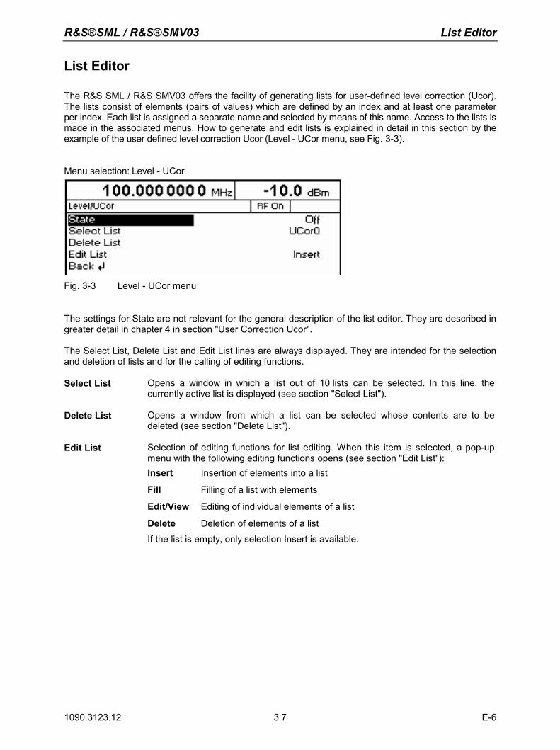
R&S®SML / R&S®SMV03 List Editor
1090.3123.12 E-6 3.7
List Editor
The R&S SML / R&S SMV03 offers the facility of generating lists for user-defined level correction (Ucor). The lists consist of elements (pairs of values) which are defined by an index and at least one parameter per index. Each list is assigned a separate name and selected by means of this name. Access to the lists is made in the associated menus. How to generate and edit lists is explained in detail in this section by the example of the user defined level correction Ucor (Level - UCor menu, see Fig. 3-3).
Menu selection: Level - UCor
Fig. 3-3 Level - UCor menu
The settings for State are not relevant for the general description of the list editor. They are described in greater detail in chapter 4 in section "User Correction Ucor". The Select List, Delete List and Edit List lines are always displayed. They are intended for the selection and deletion of lists and for the calling of editing functions. Select List Opens a window in which a list out of 10 lists can be selected. In this line, the
currently active list is displayed (see section "Select List").
Delete List Opens a window from which a list can be selected whose contents are to be deleted (see section "Delete List").
Edit List Selection of editing functions for list editing. When this item is selected, a pop-up menu with the following editing functions opens (see section "Edit List"): Insert Insertion of elements into a list
Fill Filling of a list with elements
Edit/View Editing of individual elements of a list
Delete Deletion of elements of a list
If the list is empty, only selection Insert is available.
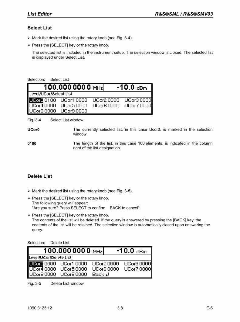
List Editor R&S®SML / R&S®SMV03
1090.3123.12 E-6 3.8
Select List
Mark the desired list using the rotary knob (see Fig. 3-4).
Press the [SELECT] key or the rotary knob.
The selected list is included in the instrument setup. The selection window is closed. The selected list is displayed under Select List.
Selection: Select List
Fig. 3-4 Select List window
UCor0 The currently selected list, in this case Ucor0, is marked in the selection window.
0100 The length of the list, in this case 100 elements, is indicated in the column right of the list designation.
Delete List
Mark the desired list using the rotary knob (see Fig. 3-5).
Press the [SELECT] key or the rotary knob. The following query will appear: "Are you sure? Press SELECT to confirm BACK to cancel".
Press the [SELECT] key or the rotary knob. The contents of the list will be deleted. If the query is answered by pressing the [BACK] key, the contents of the list will be retained. The selection window is automatically closed upon answering the query.
Selection: Delete List
Fig. 3-5 Delete List window
R&S®SML / R&S®SMV03 List Editor
1090.3123.12 E-6 3.9
Edit List
When Edit List is selected, a pop-up menu with the editing functions opens.
Insert editing function (see Fig. 3-6) The Insert function inserts a desired number of elements with constant or linearly increasing/decreasing values ahead of the element with the indicated start index. All elements already existing from the start index are shifted so that they come at the end of the range of elements to be inserted. Elements are inserted in a list according to the following procedure: When Insert has been selected, the menu cursor is on the Insert At menu item. Press the [SELECT] key or the rotary knob.
The menu cursor is on the value for At.
Vary the index value by means of the rotary knob or enter an index value using the numerical keys and the [ENTER] key.
Press the [SELECT] key or the rotary knob. The menu cursor is on the value for Range.
Vary the Range value by means of the rotary knob or enter a value using the numerical keys and the [ENTER] key.
Press the [SELECT] key or the rotary knob. The menu cursor is on the value for Start Frequency.
Vary the start value for the frequency by means of the rotary knob or enter a value using the numerical keys and the [ENTER] key.
Press the [SELECT] key or the rotary knob. The menu cursor is on the value for Increment Frequency.
Vary the value of the increment by means of the rotary knob or enter a value using the numerical keys and the [ENTER] key.
Press the [SELECT] key or the rotary knob. The menu cursor is on the value for Power.
Vary the start value for the power by means of the rotary knob or enter a value using the numerical keys and the [ENTER] key.
Press the [SELECT] key or the rotary knob. The menu cursor is on the value for Increment Power.
Vary the value of the increment by means of the rotary knob or enter a value using the numerical keys and the [ENTER] key.
The cursor is on Execute. Press the [SELECT] key or the rotary knob to execute the insertion. The menu cursor goes back to Edit List.
Upon pressing the [BACK] key, the editing window is exited without any change being made. The menu cursor goes back to Edit List.
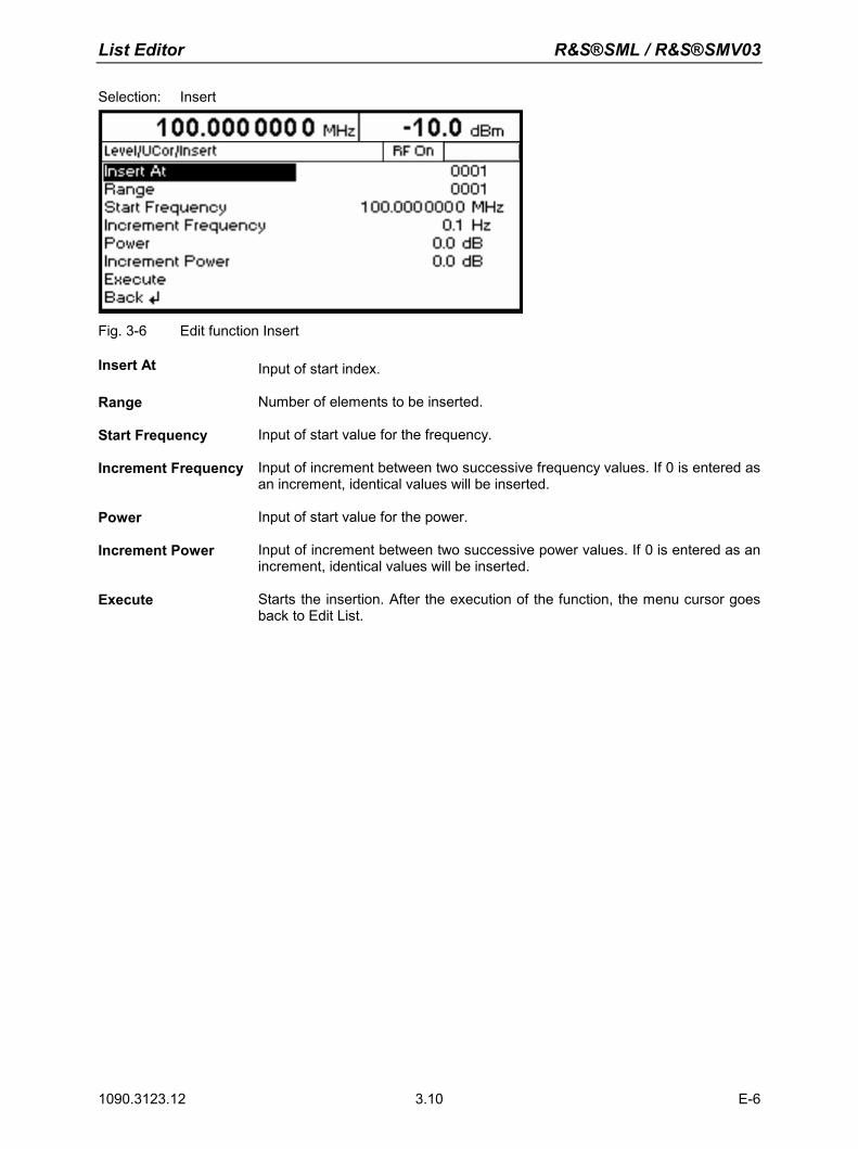
List Editor R&S®SML / R&S®SMV03
1090.3123.12 E-6 3.10
Selection: Insert
Fig. 3-6 Edit function Insert
Insert At Input of start index.
Range Number of elements to be inserted.
Start Frequency Input of start value for the frequency.
Increment Frequency Input of increment between two successive frequency values. If 0 is entered as an increment, identical values will be inserted.
Power Input of start value for the power.
Increment Power Input of increment between two successive power values. If 0 is entered as an increment, identical values will be inserted.
Execute Starts the insertion. After the execution of the function, the menu cursor goes back to Edit List.
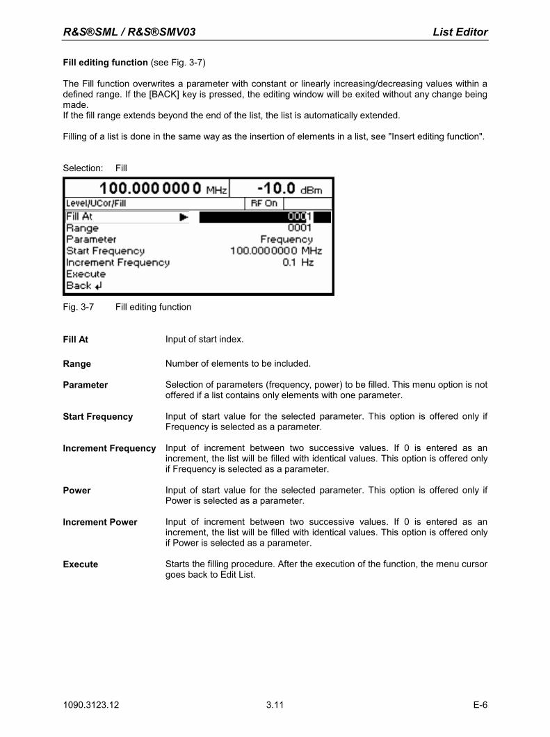
R&S®SML / R&S®SMV03 List Editor
1090.3123.12 E-6 3.11
Fill editing function (see Fig. 3-7)
The Fill function overwrites a parameter with constant or linearly increasing/decreasing values within a defined range. If the [BACK] key is pressed, the editing window will be exited without any change being made. If the fill range extends beyond the end of the list, the list is automatically extended. Filling of a list is done in the same way as the insertion of elements in a list, see "Insert editing function".
Selection: Fill
Fig. 3-7 Fill editing function
Fill At Input of start index.
Range Number of elements to be included.
Parameter Selection of parameters (frequency, power) to be filled. This menu option is not
offered if a list contains only elements with one parameter.
Start Frequency Input of start value for the selected parameter. This option is offered only if Frequency is selected as a parameter.
Increment Frequency Input of increment between two successive values. If 0 is entered as an increment, the list will be filled with identical values. This option is offered only if Frequency is selected as a parameter.
Power Input of start value for the selected parameter. This option is offered only if Power is selected as a parameter.
Increment Power Input of increment between two successive values. If 0 is entered as an increment, the list will be filled with identical values. This option is offered only if Power is selected as a parameter.
Execute Starts the filling procedure. After the execution of the function, the menu cursor goes back to Edit List.
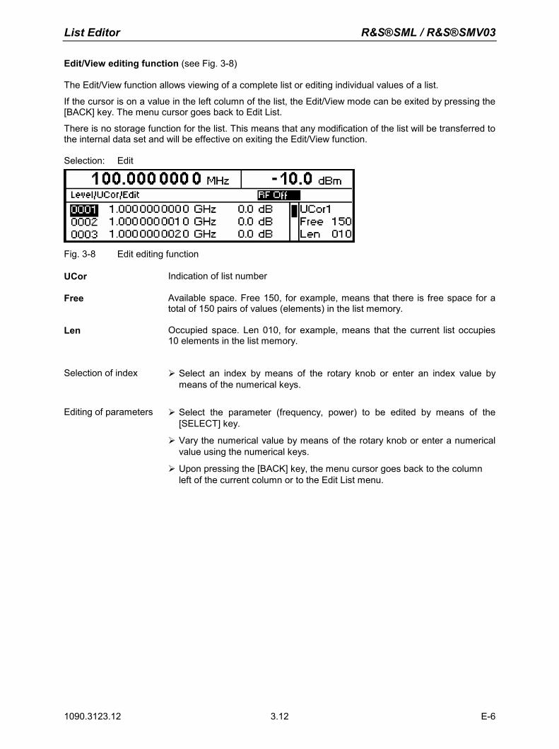
List Editor R&S®SML / R&S®SMV03
1090.3123.12 E-6 3.12
Edit/View editing function (see Fig. 3-8)
The Edit/View function allows viewing of a complete list or editing individual values of a list. If the cursor is on a value in the left column of the list, the Edit/View mode can be exited by pressing the [BACK] key. The menu cursor goes back to Edit List. There is no storage function for the list. This means that any modification of the list will be transferred to the internal data set and will be effective on exiting the Edit/View function. Selection: Edit
Fig. 3-8 Edit editing function
UCor Indication of list number
Free Available space. Free 150, for example, means that there is free space for a total of 150 pairs of values (elements) in the list memory.
Len Occupied space. Len 010, for example, means that the current list occupies 10 elements in the list memory.
Selection of index Select an index by means of the rotary knob or enter an index value by means of the numerical keys.
Editing of parameters Select the parameter (frequency, power) to be edited by means of the
[SELECT] key.
Vary the numerical value by means of the rotary knob or enter a numerical value using the numerical keys.
Upon pressing the [BACK] key, the menu cursor goes back to the column left of the current column or to the Edit List menu.
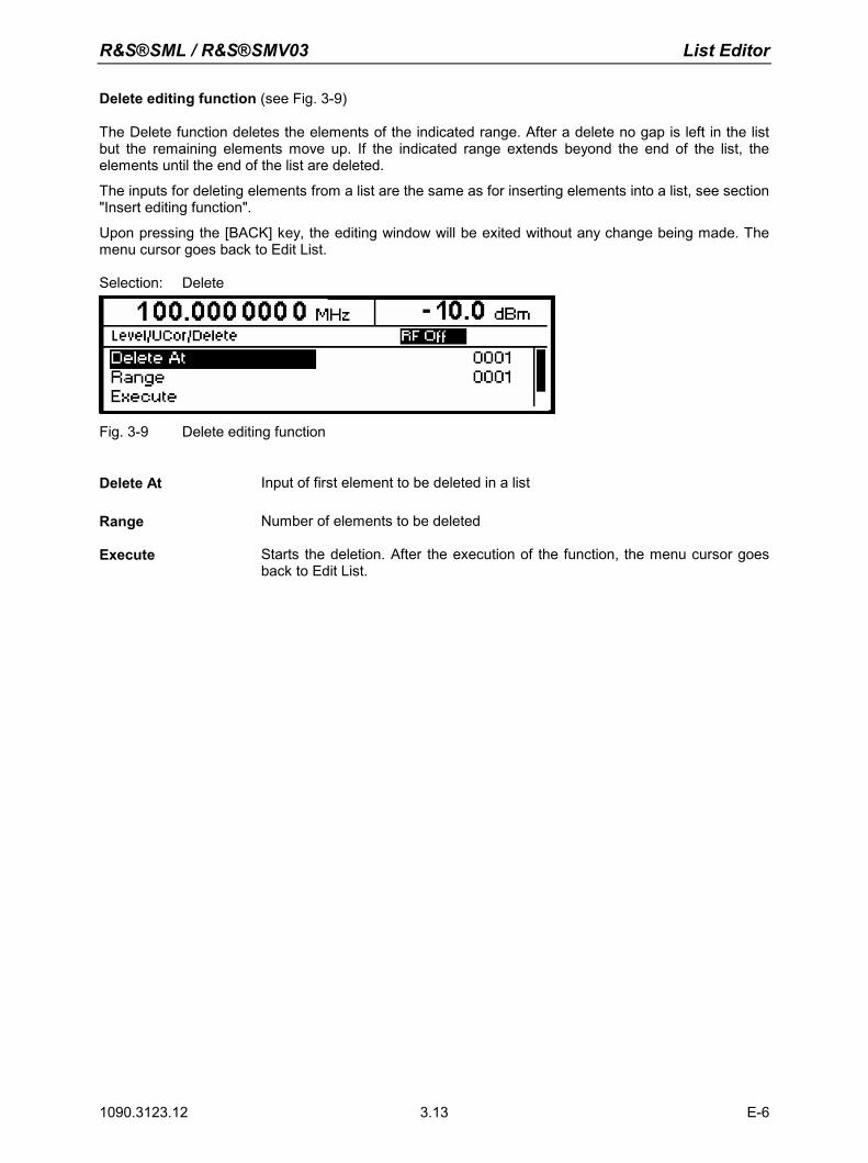
R&S®SML / R&S®SMV03 List Editor
1090.3123.12 E-6 3.13
Delete editing function (see Fig. 3-9) The Delete function deletes the elements of the indicated range. After a delete no gap is left in the list but the remaining elements move up. If the indicated range extends beyond the end of the list, the elements until the end of the list are deleted. The inputs for deleting elements from a list are the same as for inserting elements into a list, see section "Insert editing function". Upon pressing the [BACK] key, the editing window will be exited without any change being made. The menu cursor goes back to Edit List. Selection: Delete
Fig. 3-9 Delete editing function
Delete At Input of first element to be deleted in a list
Range Number of elements to be deleted
Execute Starts the deletion. After the execution of the function, the menu cursor goes
back to Edit List.
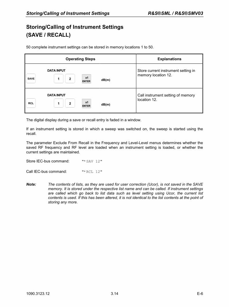
Storing/Calling of Instrument Settings R&S®SML / R&S®SMV03
1090.3123.12 E-6 3.14
Storing/Calling of Instrument Settings (SAVE / RECALL)
50 complete instrument settings can be stored in memory locations 1 to 50.
Operating Steps Explanations
SAVE
DATA INPUT
x1ENTER
1 2 dB(m)
Store current instrument setting in memory location 12.
RCL
DATA INPUT
x1ENTER
1 2 dB(m)
Call instrument setting of memory location 12.
The digital display during a save or recall entry is faded in a window. If an instrument setting is stored in which a sweep was switched on, the sweep is started using the recall. The parameter Exclude From Recall in the Frequency and Level-Level menus determines whether the saved RF frequency and RF level are loaded when an instrument setting is loaded, or whether the current settings are maintained. Store IEC-bus command: "*SAV 12"
Call IEC-bus command: "*RCL 12"
Note: The contents of lists, as they are used for user correction (Ucor), is not saved in the SAVE memory. It is stored under the respective list name and can be called. If instrument settings are called which go back to list data such as level setting using Ucor, the current list contents is used. If this has been altered, it is not identical to the list contents at the point of storing any more.
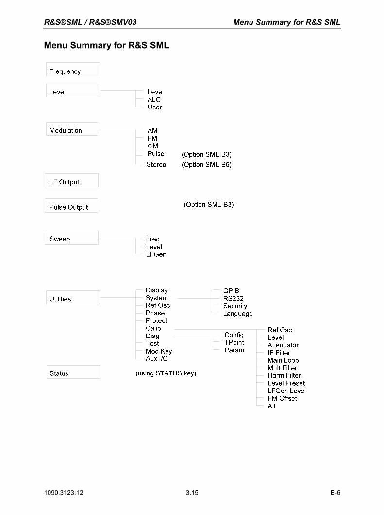
R&S®SML / R&S®SMV03 Menu Summary for R&S SML
1090.3123.12 E-6 3.15
Menu Summary for R&S SML
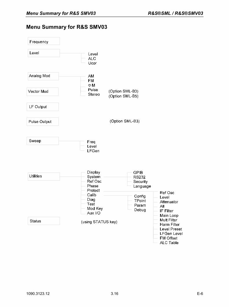
Menu Summary for R&S SMV03 R&S®SML / R&S®SMV03
1090.3123.12 E-6 3.16
Menu Summary for R&S SMV03
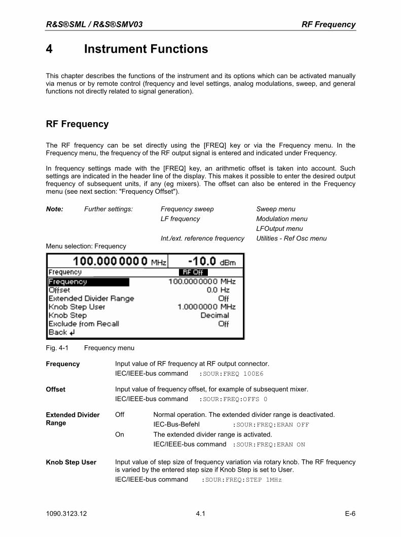
R&S®SML / R&S®SMV03 RF Frequency
1090.3123.12 4.1 E-6
4 Instrument Functions
This chapter describes the functions of the instrument and its options which can be activated manually via menus or by remote control (frequency and level settings, analog modulations, sweep, and general functions not directly related to signal generation).
RF Frequency
The RF frequency can be set directly using the [FREQ] key or via the Frequency menu. In the Frequency menu, the frequency of the RF output signal is entered and indicated under Frequency. In frequency settings made with the [FREQ] key, an arithmetic offset is taken into account. Such settings are indicated in the header line of the display. This makes it possible to enter the desired output frequency of subsequent units, if any (eg mixers). The offset can also be entered in the Frequency menu (see next section: "Frequency Offset"). Note: Further settings: Frequency sweep Sweep menu LF frequency Modulation menu LFOutput menu Int./ext. reference frequency Utilities - Ref Osc menu Menu selection: Frequency
Fig. 4-1 Frequency menu
Frequency Input value of RF frequency at RF output connector. IEC/IEEE-bus command :SOUR:FREQ 100E6
Offset Input value of frequency offset, for example of subsequent mixer. IEC/IEEE-bus command :SOUR:FREQ:OFFS 0
Extended Divider Range
Off Normal operation. The extended divider range is deactivated. IEC-Bus-Befehl :SOUR:FREQ:ERAN OFF On The extended divider range is activated. IEC/IEEE-bus command :SOUR:FREQ:ERAN ON
Knob Step User Input value of step size of frequency variation via rotary knob. The RF frequency is varied by the entered step size if Knob Step is set to User. IEC/IEEE-bus command :SOUR:FREQ:STEP 1MHz
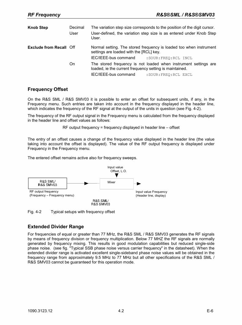
RF Frequency R&S®SML / R&S®SMV03
1090.3123.12 E-6 4.2
Knob Step Decimal The variation step size corresponds to the position of the digit cursor. User User-defined, the variation step size is as entered under Knob Step
User.
Exclude from Recall Off Normal setting. The stored frequency is loaded too when instrument settings are loaded with the [RCL] key.
IEC/IEEE-bus command :SOUR:FREQ:RCL INCL On The stored frequency is not loaded when instrument settings are
loaded, ie the current frequency setting is maintained. IEC/IEEE-bus command :SOUR:FREQ:RCL EXCL
Frequency Offset
On the R&S SML / R&S SMV03 it is possible to enter an offset for subsequent units, if any, in the Frequency menu. Such entries are taken into account in the frequency displayed in the header line, which indicates the frequency of the RF signal at the output of the units in question (see Fig. 4-2). The frequency of the RF output signal in the Frequency menu is calculated from the frequency displayed in the header line and offset values as follows:
RF output frequency = frequency displayed in header line – offset
The entry of an offset causes a change of the frequency value displayed in the header line (the value taking into account the offset is displayed). The value of the RF output frequency is displayed under Frequency in the Frequency menu. The entered offset remains active also for frequency sweeps.
Input valueOffset, L.O.
RF output frequency(Frequency – Frequency menu)
Mixer
Input value Frequency(Header line, display)
Fig. 4-2 Typical setups with frequency offset
Extended Divider Range For frequencies of equal or greater than 77 MHz, the R&S SML / R&S SMV03 generates the RF signals by means of frequency division or frequency multiplication. Below 77 MHZ the RF signals are normally generated by frequency mixing. This results in good modulation capabilities but reduced single-side phase noise. (see fig. "Typical SSB phase noise versus carrier frequency" in the datasheet). When the extended divider range is activated excellent single-sideband phase noise values will be obtained in the frequency range from approximately 9.5 MHz to 77 MHz but all other specifications of the R&S SML / R&S SMV03 cannot be guaranteed for this operation mode.
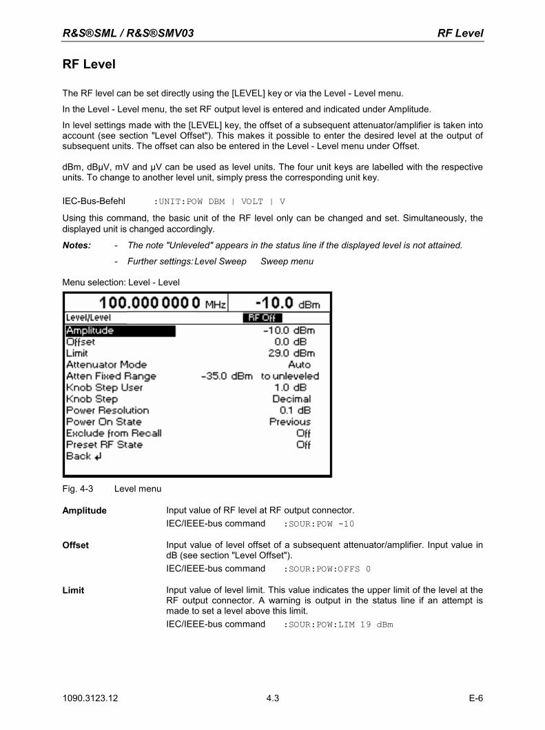
R&S®SML / R&S®SMV03 RF Level
1090.3123.12 4.3 E-6
RF Level
The RF level can be set directly using the [LEVEL] key or via the Level - Level menu. In the Level - Level menu, the set RF output level is entered and indicated under Amplitude. In level settings made with the [LEVEL] key, the offset of a subsequent attenuator/amplifier is taken into account (see section "Level Offset"). This makes it possible to enter the desired level at the output of subsequent units. The offset can also be entered in the Level - Level menu under Offset. dBm, dBµV, mV and µV can be used as level units. The four unit keys are labelled with the respective units. To change to another level unit, simply press the corresponding unit key. IEC-Bus-Befehl :UNIT:POW DBM | VOLT | V Using this command, the basic unit of the RF level only can be changed and set. Simultaneously, thedisplayed unit is changed accordingly.
Notes: - The note "Unleveled" appears in the status line if the displayed level is not attained.
- Further settings: Level Sweep Sweep menu Menu selection: Level - Level
Fig. 4-3 Level menu
Amplitude Input value of RF level at RF output connector. IEC/IEEE-bus command :SOUR:POW -10
Offset Input value of level offset of a subsequent attenuator/amplifier. Input value in dB (see section "Level Offset"). IEC/IEEE-bus command :SOUR:POW:OFFS 0
Limit Input value of level limit. This value indicates the upper limit of the level at the RF output connector. A warning is output in the status line if an attempt is made to set a level above this limit. IEC/IEEE-bus command :SOUR:POW:LIM 19 dBm
RF Level R&S®SML / R&S®SMV03
1090.3123.12 E-6 4.4
Attenuator Mode Auto Normal setting. The electronically switched attenuator switches in steps of 5 dB at fixed points.
IEC/IEEE-bus command :OUTP:AMOD AUTO Fixed Level settings are made without switching the attenuator (see
section "Non-Interrupting Level Setting"). IEC/IEEE-bus command :OUTP:AMOD FIX
Atten Fixed Range Indicates the level range of non-interrupting level setting in "Attenuator Mode Fixed". IEC/IEEE-bus command :OUTP:AFIX:RANG:LOW?
(only lower value querable)
Knob Step User Input value of step size of level variation via rotary knob. The RF level is varied by the entered step size if Knob Step is set to User. IEC/IEEE-bus command :SOUR:POW:STEP 1
Knob Step Decimal The variation step size corresponds to the position of the digit cursor.User User-defined, the variation step size is as entered under Knob Step
User (only in dB). IEC/IEEE-bus command :SOUR:POW UP / :SOUR:POW DOWN
(The RF level is always in-/decremented by the given step value, no special switching to Knob Step User.)
Power Resolution Selection of resolution of level display
0.1 dB The resolution of the level display is 0.1 dB. 0.01 dB The resolution of the level display is 0.01 dB.
Power On State Selection of status to be assumed by RF output after power-up of the instrument. RF Off The RF output is switched off. Previous Setting The RF output assumes the status active before switch-off.IEC/IEEE-bus command :OUTP:PON OFF
Exclude from Recall Off Normal setting. The stored RF level is loaded too when instrument settings are loaded with the [RCL] key.
IEC/IEEE-bus command :SOUR:POW:RCL INCL On The stored RF level is not loaded when instrument settings are
loaded, ie the current level setting is maintained. IEC/IEEE-bus command :SOUR:POW:RCL EXCL
Preset RF State Off After preset, the RF state is "Off", On After preset, the RF state is "Off". IEC/IEEE-bus command -
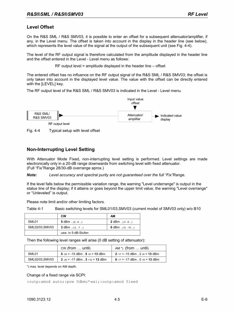
R&S®SML / R&S®SMV03 RF Level
1090.3123.12 4.5 E-6
Level Offset
On the R&S SML / R&S SMV03, it is possible to enter an offset for a subsequent attenuator/amplifier, if any, in the Level menu. The offset is taken into account in the display in the header line (see below), which represents the level value of the signal at the output of the subsequent unit (see Fig. 4-4).
The level of the RF output signal is therefore calculated from the amplitude displayed in the header line and the offset entered in the Level - Level menu as follows:
RF output level = amplitude displayed in the header line – offset The entered offset has no influence on the RF output signal of the R&S SML / R&S SMV03; the offset is only taken into account in the displayed level value. The value with the offset can be directly entered with the [LEVEL] key.
The RF output level of the R&S SML / R&S SMV03 is indicated in the Level - Level menu.
Input value offset
RF output level
Attenuator/ amplifier
Indicated value display
R&S SML/R&S SMV03
Fig. 4-4 Typical setup with level offset
Non-Interrupting Level Setting
With Attenuator Mode Fixed, non-interrupting level setting is performed. Level settings are made electronically only in a 20-dB range downwards from switching level with fixed attenuator. (Full “Fix”Range 28/30-dB overrange aprox.)
Note: Level accuracy and spectral purity are not guaranteed over the full “Fix”Range. If the level falls below the permissible variation range, the warning "Level underrange" is output in the status line of the display; if it attains or goes beyond the upper limit value, the warning "Level overrange" or “Unleveled” is output. Please note limit and/or other limiting factors.
Table 4-1 Basic switching levels for SML01/03,SMV03 (current model of SMV03 only) w/o B10
CW AM
SML01 5 dBm ...(0, -5 ...) 2 dBm ...(-3 -8 ...)
SML02/03,SMV03 3 dBm ...(-2, -7 ...) 0 dBm ...(-5, -10 ...)
usw. in 5-dB-Stufen
Then the following level ranges will arise (0 dB setting of attenuator):
CW (from … until) AM *) (from … until)SML01 5 -20 = -15 dBm , 5 +8 = 13 dBm 2 -17 = -15 dBm , 2 +8 = 13 dBm
SML02/03,SMV03 3 -20 = -17 dBm , 3 +10 = 13 dBm 0 -17 = -17 dBm , 0 +8 = 13 dBm
*) max. level depends on AM depth. Change of a fixed range via SCPI: :outp:amod auto;:pow 0dbm;*wai;:outp:amod fixed
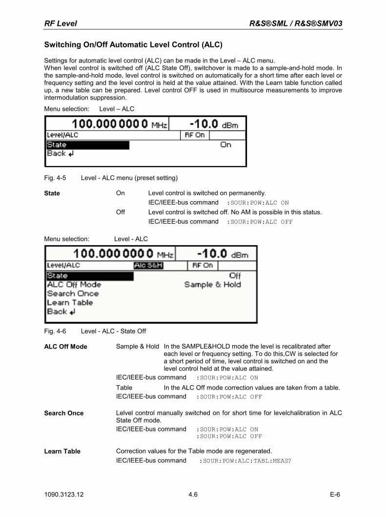
RF Level R&S®SML / R&S®SMV03
1090.3123.12 E-6 4.6
Switching On/Off Automatic Level Control (ALC)
Settings for automatic level control (ALC) can be made in the Level – ALC menu. When level control is switched off (ALC State Off), switchover is made to a sample-and-hold mode. In the sample-and-hold mode, level control is switched on automatically for a short time after each level or frequency setting and the level control is held at the value attained. With the Learn table function called up, a new table can be prepared. Level control OFF is used in multisource measurements to improve intermodulation suppression. Menu selection: Level – ALC
Fig. 4-5 Level - ALC menu (preset setting)
State On Level control is switched on permanently. IEC/IEEE-bus command :SOUR:POW:ALC ON Off Level control is switched off. No AM is possible in this status. IEC/IEEE-bus command :SOUR:POW:ALC OFF
Menu selection: Level - ALC
Fig. 4-6 Level - ALC - State Off
ALC Off Mode
Sample & Hold In the SAMPLE&HOLD mode the level is recalibrated after each level or frequency setting. To do this,CW is selected for a short period of time, level control is switched on and the level control held at the value attained.
IEC/IEEE-bus command :SOUR:POW:ALC ON Table In the ALC Off mode correction values are taken from a table. IEC/IEEE-bus command :SOUR:POW:ALC OFF
Search Once Lelvel control manually switched on for short time for levelchalibration in ALC State Off mode. IEC/IEEE-bus command :SOUR:POW:ALC ON
:SOUR:POW:ALC OFF
Learn Table Correction values for the Table mode are regenerated. IEC/IEEE-bus command :SOUR:POW:ALC:TABL:MEAS?
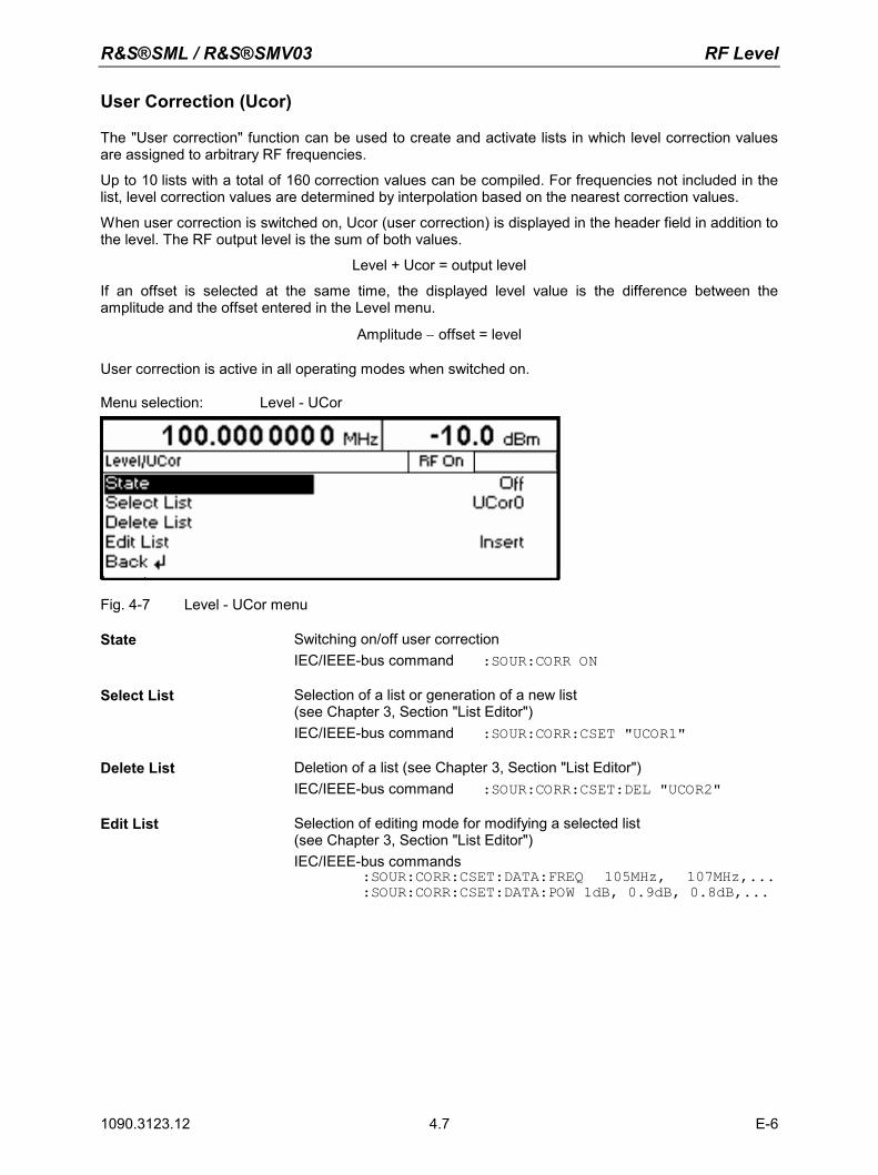
R&S®SML / R&S®SMV03 RF Level
1090.3123.12 4.7 E-6
User Correction (Ucor)
The "User correction" function can be used to create and activate lists in which level correction values are assigned to arbitrary RF frequencies. Up to 10 lists with a total of 160 correction values can be compiled. For frequencies not included in the list, level correction values are determined by interpolation based on the nearest correction values. When user correction is switched on, Ucor (user correction) is displayed in the header field in addition to the level. The RF output level is the sum of both values.
Level + Ucor = output level
If an offset is selected at the same time, the displayed level value is the difference between the amplitude and the offset entered in the Level menu.
Amplitude − offset = level User correction is active in all operating modes when switched on. Menu selection: Level - UCor
Fig. 4-7 Level - UCor menu
State Switching on/off user correction IEC/IEEE-bus command :SOUR:CORR ON
Select List Selection of a list or generation of a new list (see Chapter 3, Section "List Editor") IEC/IEEE-bus command :SOUR:CORR:CSET "UCOR1"
Delete List Deletion of a list (see Chapter 3, Section "List Editor") IEC/IEEE-bus command :SOUR:CORR:CSET:DEL "UCOR2"
Edit List Selection of editing mode for modifying a selected list (see Chapter 3, Section "List Editor") IEC/IEEE-bus commands :SOUR:CORR:CSET:DATA:FREQ 105MHz, 107MHz,...
:SOUR:CORR:CSET:DATA:POW 1dB, 0.9dB, 0.8dB,...
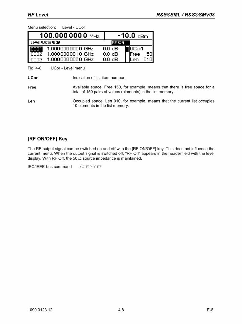
RF Level R&S®SML / R&S®SMV03
1090.3123.12 E-6 4.8
Menu selection: Level - UCor
Fig. 4-8 UCor - Level menu
UCor Indication of list item number.
Free Available space. Free 150, for example, means that there is free space for a total of 150 pairs of values (elements) in the list memory.
Len Occupied space. Len 010, for example, means that the current list occupies 10 elements in the list memory.
[RF ON/OFF] Key
The RF output signal can be switched on and off with the [RF ON/OFF] key. This does not influence the current menu. When the output signal is switched off, "RF Off" appears in the header field with the level display. With RF Off, the 50 Ω source impedance is maintained. IEC/IEEE-bus command :OUTP OFF
R&S®SML / R&S®SMV03 Modulation - General
1090.3123.12 4.9 E-6
Modulation - General
The R&S SML / R&S SMV03 offers the following modulation types : • Amplitude modulation (AM),
• Frequency modulation (FM),
• Phase modulation (ΦM),
• Pulse modulation PULSE (Option R&S SML-B3),
• Stereo modulation STEREO (Option R&S SML-B5),
• Vector modulation VECTOR (R&S SMV03 only),
For all modulations except vector modulation an internal or external modulation source can be used. For stereo modulation external analog R or L signals can be applied. The operation modes R, L, R=L, R=-L and R≠L are available. In addition the R&S SML / R&S SMV03 provides an S/P DIF input for externally generated digital stereo signals. Vector modulation requires external modulation signals.
Modulation Sources
Internal modulation source For AM and FM/ΦM, an internal modulation generator (Lfgen) is available. For more information see section "LF Generator". ". The generator can also be used for analog stereo modulation. In this case the operation modes R, L, R=L, R=-L are available. For more information see section "Stereo Modulation (option R&S SML-B5)".
For internal pulse modulation (option R&S SML-B3), the instrument is equipped with a pulse generator. For more information see section "Pulse Generator".
External modulation source for AM, FM/ΦM) and PULSE
For external modulation, input connectors MOD (AM, FM/ΦM) and PULSE (Pulse modualtion) are available. External AM and FM/ΦM can be AC- or DC-coupled. External modulation signals should have a voltage of Vp = 1 V (Vrms = 0.707 V) to maintain the displayed modulation depth or deviation.
External modulation sources for stereo modulation For external analog stereo modulation, input connectors STEREO R and STEREO L are available at the rear panel of the R&S SML / R&S SMV03 . External modulation signals should have a voltage of Vp = 1 V (Vrms = 0.707 V) to maintain the displayed frequency deviation. For external digital stereo modulation the unsymmetrical BNC input connector S/P DIF is available (input impedance of 75 Ω). The external modulation signal should have a voltage of Vpp = 400 mV to Vpp = 5 V.
Modulation - General R&S®SML / R&S®SMV03
1090.3123.12 E-6 4.10
Extrenal modulation sources for vector modulation For external vector modulation, input connectors I and Q are available at the rear panel of the SMV03 (input impedances 50 Ω). To avoid the I/Q modulator being overdriven the input voltage should never exceed √I2 + Q2 = 0.5 V.
Simultaneous Modulation
If vector modulation is deactivated then basically any combination of AM, FM/ΦM/stereo and pulse modulation is possible. There are restrictions only for FM,ΦM. and stereo. The same is true for activated vector modulation. Though, then there is an additional restriction for AM. Two-tone AM and two-tone FM/ΦM can be selected via menu (Modulation - AM (FM/ΦM) - AM (FM/ΦM) Source - Two Tone).
Mutual Switch-Off of Modulation Types
As FM,ΦM and stereo use the same modulator, they cannot be activated simultaneously. They deactivate one another. In a similar way the same is true for AM and vector modulation. For AM the level control has to be activated while vector modulation requires the level control being deactivated.
Note: IEC/IEEE-bus control according to SCPI does not allow the selection of the incompatible modulation types FM,ΦM and stereo. With remote control, an error message is output when an attempt is made to activate these types of modulation (see Chapter 9).
[MOD ON/OFF] Key
The various types of modulation can be switched on and off directly using the [MOD ON/OFF] key or via the Modulation menu. If switch-on is made using the [MOD ON/OFF] key, the modulation sources which are set in the modulation menus are used. The [MOD ON/OFF] key can be effective either for all types of modulation or only for a selected modulation. The selection of modulation types for which the [MOD ON/OFF] key is to be effective is made in the Utilities – Mod Key menu. If only one type of modulation is selected, it is switched on or off each time the [MOD ON/OFF] key is pressed. If all modulation types are selected, the [MOD ON/OFF] key has the following effect: • If at least one modulation type is active:
Pressing the [MOD ON/OFF] key switches off all active modulation types. The modulation types which were active are stored.
• If no modulation type is active: Pressing the [MOD ON/OFF] key switches on the modulation types that were last switched off with this key.
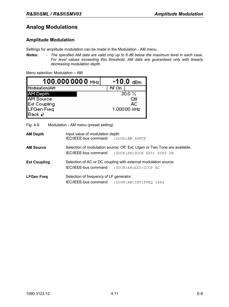
R&S®SML / R&S®SMV03 Amplitude Modulation
1090.3123.12 4.11 E-6
Analog Modulations
Amplitude Modulation
Settings for amplitude modulation can be made in the Modulation - AM menu. Notes: - The specified AM data are valid only up to 6 dB below the maximum level in each case.
For level values exceeding this threshold, AM data are guaranteed only with linearly decreasing modulation depth.
Menu selection: Modulation – AM
Fig. 4-9 Modulation - AM menu (preset setting)
AM Depth Input value of modulation depth IEC/IEEE-bus command :SOUR:AM 30PCT
AM Source Selection of modulation source; Off, Ext, Lfgen or Two Tone are available. IEC/IEEE-bus command :SOUR:AM:SOUR EXT; STAT ON
Ext Coupling Selection of AC or DC coupling with external modulation source IEC/IEEE-bus command :SOUR:AM:EXT:COUP AC
LFGen Freq Selection of frequency of LF generator IEC/IEEE-bus command :SOUR:AM:INT:FREQ 1kHz
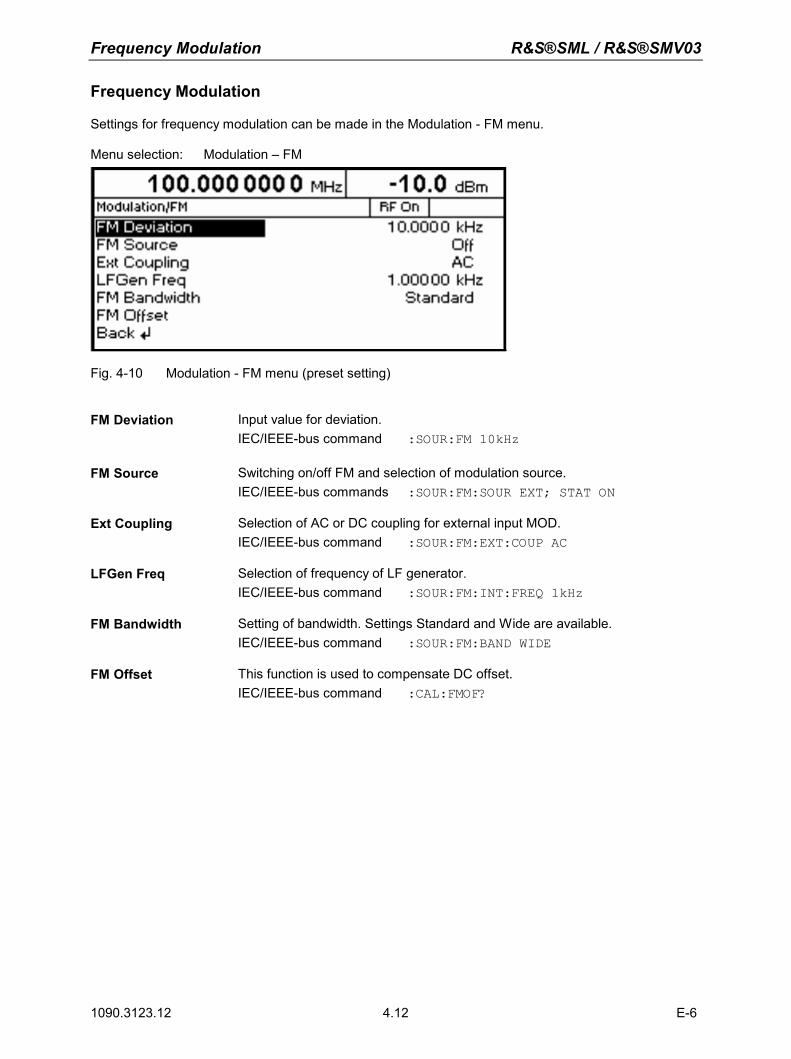
Frequency Modulation R&S®SML / R&S®SMV03
1090.3123.12 E-6 4.12
Frequency Modulation
Settings for frequency modulation can be made in the Modulation - FM menu. Menu selection: Modulation – FM
Fig. 4-10 Modulation - FM menu (preset setting)
FM Deviation Input value for deviation.
IEC/IEEE-bus command :SOUR:FM 10kHz
FM Source Switching on/off FM and selection of modulation source. IEC/IEEE-bus commands :SOUR:FM:SOUR EXT; STAT ON
Ext Coupling Selection of AC or DC coupling for external input MOD. IEC/IEEE-bus command :SOUR:FM:EXT:COUP AC
LFGen Freq Selection of frequency of LF generator. IEC/IEEE-bus command :SOUR:FM:INT:FREQ 1kHz
FM Bandwidth Setting of bandwidth. Settings Standard and Wide are available. IEC/IEEE-bus command :SOUR:FM:BAND WIDE
FM Offset This function is used to compensate DC offset. IEC/IEEE-bus command :CAL:FMOF?
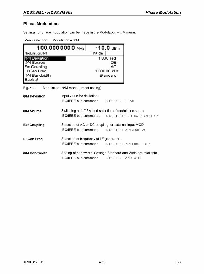
R&S®SML / R&S®SMV03 Phase Modulation
1090.3123.12 4.13 E-6
Phase Modulation
Settings for phase modulation can be made in the Modulation – ΦM menu. Menu selection: Modulation – M
Fig. 4-11 Modulation - ΦM menu (preset setting)
ΦM Deviation Input value for deviation. IEC/IEEE-bus command :SOUR:PM 1 RAD
ΦM Source Switching on/off PM and selection of modulation source. IEC/IEEE-bus commands :SOUR:PM:SOUR EXT; STAT ON
Ext Coupling Selection of AC or DC coupling for external input MOD. IEC/IEEE-bus command :SOUR:PM:EXT:COUP AC
LFGen Freq Selection of frequency of LF generator. IEC/IEEE-bus command :SOUR:PM:INT:FREQ 1kHz
ΦM Bandwidth Setting of bandwidth. Settings Standard and Wide are available. IEC/IEEE-bus command :SOUR:PM:BAND WIDE
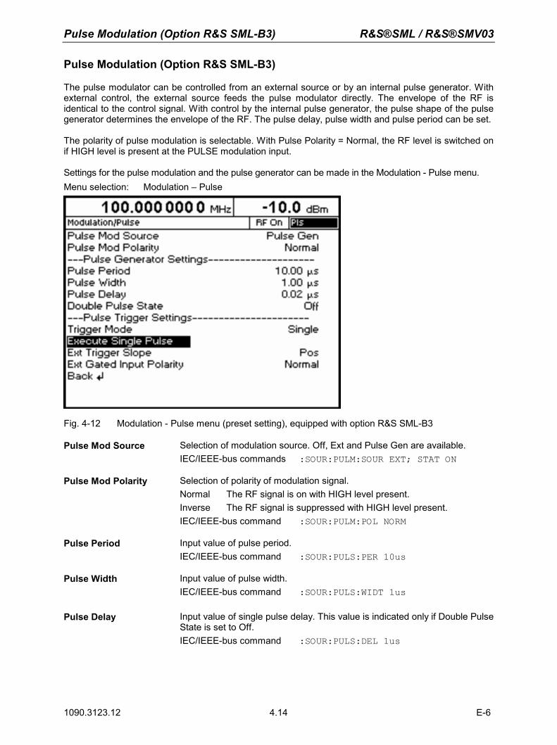
Pulse Modulation (Option R&S SML-B3) R&S®SML / R&S®SMV03
1090.3123.12 E-6 4.14
Pulse Modulation (Option R&S SML-B3)
The pulse modulator can be controlled from an external source or by an internal pulse generator. With external control, the external source feeds the pulse modulator directly. The envelope of the RF is identical to the control signal. With control by the internal pulse generator, the pulse shape of the pulse generator determines the envelope of the RF. The pulse delay, pulse width and pulse period can be set. The polarity of pulse modulation is selectable. With Pulse Polarity = Normal, the RF level is switched on if HIGH level is present at the PULSE modulation input. Settings for the pulse modulation and the pulse generator can be made in the Modulation - Pulse menu. Menu selection: Modulation – Pulse
Fig. 4-12 Modulation - Pulse menu (preset setting), equipped with option R&S SML-B3
Pulse Mod Source Selection of modulation source. Off, Ext and Pulse Gen are available. IEC/IEEE-bus commands :SOUR:PULM:SOUR EXT; STAT ON
Pulse Mod Polarity Selection of polarity of modulation signal. Normal The RF signal is on with HIGH level present. Inverse The RF signal is suppressed with HIGH level present. IEC/IEEE-bus command :SOUR:PULM:POL NORM
Pulse Period Input value of pulse period. IEC/IEEE-bus command :SOUR:PULS:PER 10us
Pulse Width Input value of pulse width. IEC/IEEE-bus command :SOUR:PULS:WIDT 1us
Pulse Delay Input value of single pulse delay. This value is indicated only if Double Pulse State is set to Off. IEC/IEEE-bus command :SOUR:PULS:DEL 1us
R&S®SML / R&S®SMV03 Pulse Modulation (Option R&S SML-B3)
1090.3123.12 4.15 E-6
Double Pulse Delay Delay between the two pulses of a double pulse. This value is indicated only if Double Pulse State is set to On. IEC/IEEE-bus command :SOUR:PULS:DOUB:DEL 1us
Double Pulse State Switching on/off double pulse. On Double pulse is switched on Off Single pulse IEC/IEEE-bus command :SOUR:PULS:DOUB:STAT OFF
Trigger Mode Selection of trigger mode. Auto The pulse generator is triggered automatically. The pulse period
is as entered under Pulse Period. Single The pulse generator is triggered manually. The pulse period is
determined by the user. Ext Single The pulse generator is externally triggered. The pulse period is
determined by an external signal at the PULSE input. Ext Gated The pulse generator is triggered if the gate signal is active. IEC/IEEE-bus command :TRIG:PULS:SOUR AUTO
Execute Single Pulse Starts a single pulse. This function is displayed and is effective only if Single Mode is selected. IEC-Bus-Befehl :TRIG:PULS:IMM
Ext Trigger Slope Selection of active edge of external trigger signal. Pos The pulse generator is triggered on the positive edge of the
external signal. Neg The pulse generator is triggered on the negative edge of the
external signal. IEC/IEEE-bus command :TRIG:PULS:SLOP POS
Ext Gated Input Polarity
Definition of active level of gate signal (HIGH or LOW). Normal (HIGH) and Inverse (LOW) are available. IEC-Bus-Befehl :TRIG:PULS:EGAT:POL NORM
Pulse Generator
As an internal modulation source, the pulse generator offers the possibility of setting single and double pulses with variable pulse delay, pulse width and pulse period. The pulse generator can be triggered internally or by an external signal at the PULSE input. The following Pulse modi can be selected: Auto Trig, Ext Trig, and Ext Gated (see Fig. 4-13 to Fig. 4-15). The internal trigger signal is derived from the reference frequency and hence very stable. In the trigger mode Ext Trig, the positive or the negative edge can be used for triggering the pulse generator. In the trigger mode Ext Gated, the pulse generator is triggered as long as an active Gate signal arrives at the PULSE input. The pulse generator can also be used as an independent unit, ie without the pulse modulator being controlled if the pulse modulation source (Pulse Source) is switched to OFF or EXT. The pulse can be tapped at the VIDEO output.
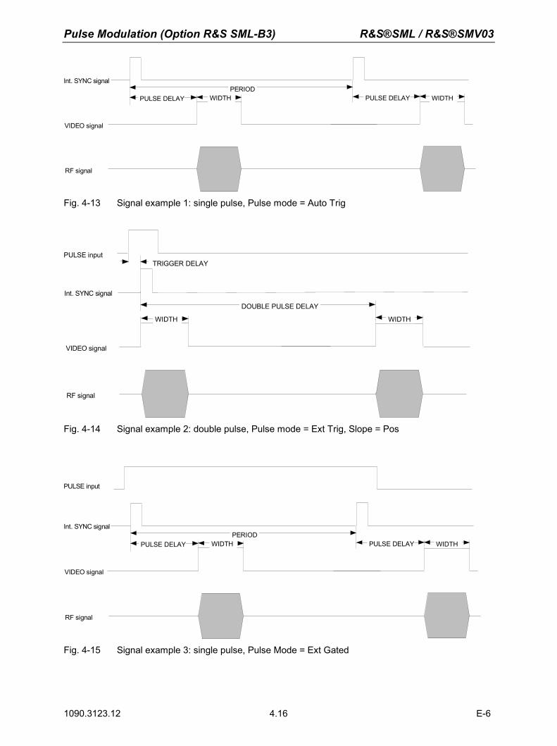
Pulse Modulation (Option R&S SML-B3) R&S®SML / R&S®SMV03
1090.3123.12 E-6 4.16
Int. SYNC signal
VIDEO signal
RF signal
PERIOD WIDTH PULSE DELAY PULSE DELAY WIDTH
Fig. 4-13 Signal example 1: single pulse, Pulse mode = Auto Trig
Int. SYNC signal
VIDEO signal
RF signal
WIDTH
TRIGGER DELAY
WIDTH
PULSE input
DOUBLE PULSE DELAY
Fig. 4-14 Signal example 2: double pulse, Pulse mode = Ext Trig, Slope = Pos
Int. SYNC signal
VIDEO signal
RF signal
PERIOD WIDTH PULSE DELAY PULSE DELAY WIDTH
PULSE input
Fig. 4-15 Signal example 3: single pulse, Pulse Mode = Ext Gated
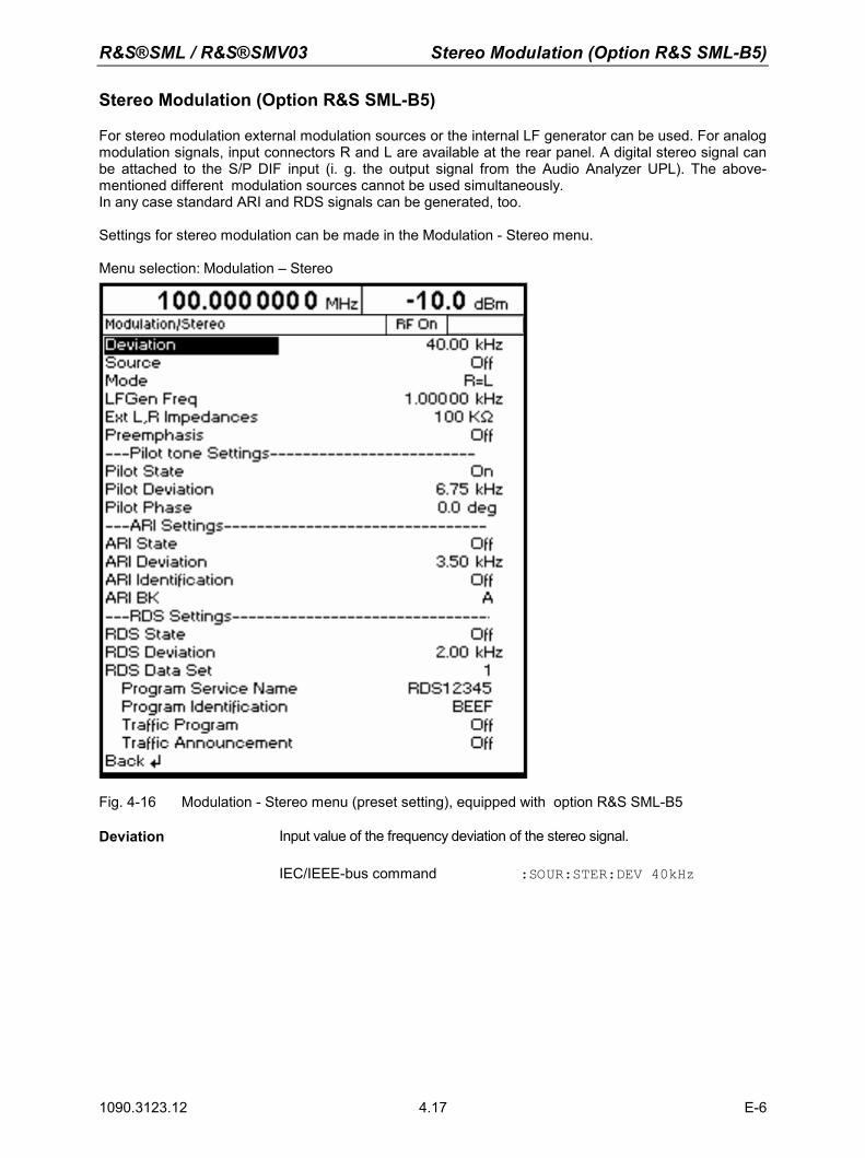
R&S®SML / R&S®SMV03 Stereo Modulation (Option R&S SML-B5)
1090.3123.12 4.17 E-6
Stereo Modulation (Option R&S SML-B5)
For stereo modulation external modulation sources or the internal LF generator can be used. For analog modulation signals, input connectors R and L are available at the rear panel. A digital stereo signal can be attached to the S/P DIF input (i. g. the output signal from the Audio Analyzer UPL). The above-mentioned different modulation sources cannot be used simultaneously. In any case standard ARI and RDS signals can be generated, too. Settings for stereo modulation can be made in the Modulation - Stereo menu. Menu selection: Modulation – Stereo
Fig. 4-16 Modulation - Stereo menu (preset setting), equipped with option R&S SML-B5
Deviation
Input value of the frequency deviation of the stereo signal. IEC/IEEE-bus command :SOUR:STER:DEV 40kHz
Stereo Modulation (Option R&S SML-B5) R&S®SML / R&S®SMV03
1090.3123.12 E-6 4.18
Source Selection of the modulation source. The sources cannot be used simultaneously. Off The stereo modulation is witched off. Ext L, R Selection of the L and R inputs for external analog modulation signals. Ext S/P DIF Selection of the S/P DIF input for the external digital modulation signal. LF Gen The modulation signal is generated by the internal LF generator. IEC/IEEE-bus command :SOUR:STER:SOUR LREX; STAT ON
Mode Selection of the operating mode. L Audio signal only in the left-hand channel. R Audio signal only in the right-hand channel. L=R Audio signals of same frequency and phase in both channels. L=-R Audio signal of same frequency but opposite phase in both
channels. L≠R Different and independent audio signals in both channels (not
possible with internal LF generator). IEC/IEEE-bus command :SOUR:STER:MODE LEQR
LFGen Freq Input value of the frequency of the LF generator. IEC/IEEE-bus command :SOUR:STER:INT:FREQ 1kHz
Ext L,R Impedances Selection of the input impedances of the analog audio inputs l and R. Both input impedances are switched simultaneously. IEC/IEEE-bus command :SOUR:STER:EXT:IMP 100kOhm
Preemphasis Selection of the preemphasis. Off Preemphasis switched off. 50 µs Preemphasis 50 µs 75 µs Preemphasis 75 µs IEC/IEEE-bus command :SOUR:STER:PRE 50us
Pilot State Switching on/off the pilot tone. On Pilot tone switched on Off Pilot tone switched off IEC/IEEE-bus command :SOUR:STER:PIL:STAT ON
Pilot Deviation Input value of the frequency deviation of the pilot tone. IEC/IEEE-bus command :SOUR:STER:PIL:DEV 6.75kHz
Pilot Phase Input value of the phase of the pilot tone (with respect to to 38 kHz subcarrier). . IEC/IEEE-bus command :SOUR:STER:PIL:PHAS 0 DEG
R&S®SML / R&S®SMV03 Stereo Modulation (Option R&S SML-B5)
1090.3123.12 4.19 E-6
ARI State
Switching on/off the ARI subcarrier.. On ARI subcarrier switched on Off ARI subcarrier switched off IEC/IEEE-bus command :SOUR:STER:ARI:STAT ON
ARI Deviation Input value of the frequency deviation of the ARI subcarrier. IEC/IEEE-bus command :SOUR:STER:ARI:DEV 3.5kHz
ARI Idendification Selection between ARI broadcasting code (DK) and traffic area code (Bk). . Off The area code and the broadcasting code are switched off. DK The broadcasting code is activated. BK The area code is activated. BK+ DK The broadcasting code and area code are activated. IEC/IEEE-bus command:SOUR:STER:ARI:IDEN DK; STAT ON
ARI BK Selection of the standard traffic area codes. A Traffic area code A B Traffic area code B C Traffic area code C D Traffic area code D E Traffic area code E F Traffic area code F IEC/IEEE-bus command: :SOUR:STER:ARI:BK A
RDS State Switching on/ff the RDS functions. On RDS switched on Off RDS switched off IEC/IEEE-bus command :SOUR:STER:STAT
RDS Deviation Input value of the frequency deviation of the RDS subcarrier. IEC/IEEE-bus command :SOUR:STER:RDS:DEV 2kHz
RDS Data Set
Selection and activation of the RDS data set. 1 RDS data set 1 2 RDS data set 2 3 RDS data set 3 4 RDS data set 4 5 RDS data set 5 IEC/IEEE-bus command :SOUR:STER:DAT DS1 The RDS data sets cannot manually be entered. They have to be sent via the IEC/IEEC bus or the RS-232 interface.
Stereo Modulation (Option R&S SML-B5) R&S®SML / R&S®SMV03
1090.3123.12 E-6 4.20
Program Service Name
Indication of the program service name of the selected RDS data set (hexadecimal value OOOO bisFFFF). Each RDS data set has its own program service name. It can only be modified over the IEC/IEEC bus or the RS-232 interface (see section "RDS commands").
Program Idendification
Indication of the program service name of the selected RDS data set (hexadecimal value OOOO bisFFFF). . Each RDS data set has its own program identification. It can only be modified over the IEC/IEEC bus or the RS-232 interface (see section "RDS commands").
Traffic Program
Switching on/off traffic programm. On Traffic program on Off Traffic program off
IEC-Bus-Befehl :SOUR:STER:RDS:TRAF:PROG ON
Traffic Announcement
Switching on/off Traffic announcement On Traffic announcement on Off Traffic announcement off
IEC-Bus-Befehl :SOUR:STER:RDS:TRAF:ANN ON
RDS commands The option R&S SML-B5 supports all important RDS commands in accordance with IEC 62106:1999 The complete RDS command set of the option can be operated over the IEC/IEEE bus or the the RS-232 interface. Some basic RDS functions can also be found in the Modulation - Stereo menu and can manually be operated, too. RDS settings via remote control: :SOUR:STER:DIR "command string" RDS queries via remote control: :SOUR:STER:DIR? ["command string"]
R&S®SML / R&S®SMV03 Stereo Modulation (Option R&S SML-B5)
1090.3123.12 4.21 E-6
Commands for the Stereo/RDS Coder Option SML-B5 Commands are sent to the Stereo/RDS Coderwith STEReo:DIRect: ["command string" Information is queried with STEReo:DIRect? ["Befehls-String"]. All commands are to be terminated with CR. Uppercase and lowercase letters are used to identify the long form and short form of the keywords of the commands given in the manual. The instrument itself does not distinguish between the two types of characters.
Commands
1A=, 3A=, 5A=, 6A=, 7A=, 8A=, 9A=, 10A=, 11A=, 12A=, 13A=
Description: Transmits data via free format groups (FFGs). A free format group can be filled with any desired data. (5 bits in block B and 16 bits each in blocks C and D of the group).
Command: 1A= WW,xxxxxxxxxx,yyyyyyyyy,... or 1A=00: erases the data
Query: 1A?
Response: xxxxxxxxxx,yyyyyyyyy,...
Value range: WW = number of retransmissions x, y = 0000000000 bis 1FFFFFFFFF (10 ASCII ccoded hexadecimal characters each) Max. 20 different data sequences can be defined.
Example: Command: STEReo:DIRect “1A=01,0123456789,1FFFFFFFFF“ Fills a queue with the data "0123456789,1FFFFFFFFF". The data is sent in consecutive order in group 1A after group 1A is added to the group sequence (see "GS" command below).
Query: STEReo:DIRect? “1A“ Reads the data of group 1A.
Response: "01,0123456789,1FFFFFFFFF"
Note: 10 characters must be specified each for x and y. Leading zeros, if any, must also be specified. The command described here only causes a queue to be filled with data for a specific group. The data will only be sent when the group in question is added to the group sequence with the "GS" command.
Stereo Modulation (Option R&S SML-B5) R&S®SML / R&S®SMV03
1090.3123.12 E-6 4.22
AF
Description: Alternative Frequenzen für die ausgestrahlte Frequenz festlegen
Command: AF=A,xxx.x,xxx.x,...
Query: AFz?
Response: xxx.x,xxx.x,... or () if list "z" is not available
Value range: xxx.x = 87.6 to 107.9 (ASCII coded decimal numbers) A = "N" (new AF list) or "+" (AF list to be added) z = 1 to 5 (AF list to be read)
Example: Command: STEReo:DIRect “AF=N,97.4,98.3“ Erstellen einer neuen alternativen Frequenzliste Es werden die alternativen Frequenzen 97.4 und 98.3 eingefügt.
Query: STEReo:DIRect? “AF1“ Reads the first alternative frequency list.
Response: "97.4,98.3"
Delete lists with: STEReo:DIRect “AF=N“ Deletes all frequency lists.
Note: A maximum of five AF lists with max. 25 frequencies per list can be created.
ARI
Description: Activates ARI signal transmission.
Command: ARI=x
Query: ARI?
Response: x
Value range: 0|1
Example: Command: STEReo:DIRect “ARI=0“ Deactivates ARI signal transmission.
Query: STEReo:DIRect? “ARI“ Response: "0"
R&S®SML / R&S®SMV03 Stereo Modulation (Option R&S SML-B5)
1090.3123.12 4.23 E-6
ARI-DEV
Description: Sets the frequency deviation of the ARI signal (max. deviation).
Command: ARI-DEV=xxxx
Query: ARI-DEV?
Response: xxxx
Value range: 0000 to 1000 (ASCII coded decimal numbers),corresponding to 0 Hz to 10 kHz
Example: Command: STEReo:DIRect “ARI-DEV=1000“ Sets the ARI frequency deviation to 10 kHz.
Query: STEReo:DIRect? “ARI-DEV“ Response: "1000"
Note: A four-digit value must always be set. Leading zeros, if any, must also be specified.
ARI-ID
Description: Selects the ARI identification.
Command: ARI-ID=x
Query: ARI-ID?
Response: x
Value range: 0|1|2|3 0 = Off 1 = DK (traffic announcement identification) 2 = BK (area identification) 3 = DK and BK (traffic announcement identification and area identification)
Example: Command: STEReo:DIRect “ARI-ID=0“ Deactivates the ARI identification.
Query: STEReo:DIRect? “ARI-ID“ Response: "0"
BIN Description: Defines and sends, or queries, binary test patterns.
The BIN command causes the Stereo/RDS Coder to send periodic binary bit patterns instead of RDS data.
Command: BIN=x Value range: 0 to 4
0 = binary mode OFF 1 = 00000000..., 2 = 11111111..., 3 = 01010101..., 4 = 11001100...
Example: Command: STEReo:DIRect "BIN=2"The binary test pattern is set to "2" so that only "1s" are transmitted.
Stereo Modulation (Option R&S SML-B5) R&S®SML / R&S®SMV03
1090.3123.12 E-6 4.24
BK
Description: Sets the ARI area identification.
Command: BK=x
Query: BK?
Response: x
Value range: A-F
Example: Command: STEReo:DIRect “BK=E“ The ARI area identification is set to "E".
Query: STEReo:DIRect? “BK“ Response: "E"
CT
Description: Sets and activates transmission of the real-time clock.
Command: CT= XX:YY:ZZ,TT.MM.JJ XX = hour, YY = minute, ZZ = second TT = day, MM = month, JJ = year
Query: CT?
Response: XX:YY:ZZ,TT.MM.JJ
Value range: 00:00:00,01.01.00 bis 23:59:59,31.12.85 (ASCII coded decimal numbers)
Example: Command: STEReo:DIRect "CT=20:30:59,01.08.03"The real-time clock is set to 20:30:59 and 1 August 2003.
Query: STEReo:DIRect? “CT“
Response: "20:31:06,01.08.03"
Note: The CT data is transmitted in group 4A. Setting the real-time clock (CT command) automatically adds group 4A to the group sequence. Group 4A must not be manually added to, or removed from, the group sequence. To remove group 4A from the group sequence, the "CT=off" command must be used.
CT=off
Description: Deactivates transmission of the real-time clock signal in the RDS signal.
Command: CT=off
Example: Command: STEReo:DIRect "CT=off"The real-time clock signal is no longer transmitted in the RDS signal.
Note: This command is used to remove group 4A from the group sequence. Group 4A must not be manually removed from the group sequence.
R&S®SML / R&S®SMV03 Stereo Modulation (Option R&S SML-B5)
1090.3123.12 4.25 E-6
DI
Description: Sets or reads the decoder information. With this command, the current decoder operating mode (mono, stereo, etc) can be detected and, if necessary, changed.
Command: DI=x
Query: DI?
Response: x
Value range: 0-F (ASCII coded hexadecimal numbers)
Example: Command: STEReo:DIRect “DI=4“ The decoder information is set to "4".
Query: STEReo:DIRect? “DI“ Response: "4"
DS
Description: Selects/activates a storage area in the Stereo/RDS Coder. Upon activation, the settings stored in the selected area can be loaded.
Command: DS=x
Query: DS?
Response: x
Value range: 1|2|3|4|5|6|7|8|9
Example: Command: STEReo:DIRect “DS=2“ Storage area 2 is activated.
Query: STEReo:DIRect? “DS“ Response: "2"

Stereo Modulation (Option R&S SML-B5) R&S®SML / R&S®SMV03
1090.3123.12 E-6 4.26
EON-AFA
Description: Enhanced Other Networks: defines type A alternative frequencies for the EON with PI=yyyy.
Command: EON-AFA= yyyy,A,xxx.x,xxx.x,...
Query: EON-AFA,yyyy,z?
Response: xxx.x,xxx.x,... or () if list "z" is not available
Value range: xxx.x = 87.6 to 107.9 (ASCII coded decimal numbers) yyyy = 0000 to FFFF (ASCII coded hexadecimal numbers) A = N“ (new AF list) or "+" (AF list to be added) z = 1-5 1 to 5 (AF list to be read)
Example: Command: STEReo:DIRect “EON-AFA=1000,N,97.4,98.3“ Creates a new type A alternative frequency list for the EON with PI=1000. The new list contains the alternative frequencies 97.4 MHz and 98.3 MHz.
Query: STEReo:DIRect? “EON-AFA,1000,1“ Reads the first type A alternative frequency list of the EON with PI=1000. Response: "97.4,98.3"
Note: For each Enhanced Other Network (EON), a maximum of five type A alternative frequency lists can be created.
EON-AFB
Description: Enhanced Other Networks: defines type B alternative frequencies for the EON with PI=yyyy.
Command: EON-AFB= yyyy,A,xxx.x,xxx.x,... 1. Freq = Tuned Frequenz (TF) 2. bis 5. Freq = Mapped Frequenz (MF)
Query: EON-AFB,yyyy,z?
Response: xxx.x,xxx.x,... or () if list "z" is not available ist
Value range: xxx.x = 87.6 to 107.9 (ASCII coded decimal numbers) yyyy = 0000 to FFFF (ASCII coded hexadecimal numbers) A = "N" (new AF list) or "+" (AF list to be added) z = 1 to 5 (AF list to be read)
Example: Command: STEReo:DIRect “EON-AFB=1000,N,97.4,98.3“ Creates a new type B alternative frequency list for the EON with PI=1000. The list contains the alternative frequencies 97.4 MHz and 98.3 MHz.
Query: STEReo:DIRect? “EON-AFB,1000,1“ Reads the first type B alternative frequency list of the EON with PI=1000.
Response: "97.4,98.3"
Note: For each Enhanced Other Network (EON), a maximum of five type B alternative frequency lists can be created, each list containing max. five frequencies. A minimum of two frequencies per EON is required.
R&S®SML / R&S®SMV03 Stereo Modulation (Option R&S SML-B5)
1090.3123.12 4.27 E-6
EON-DEL
Description: Enhanced Other Networks: deletes the complete EON with PI=xxxx.
Command: EON-DEL=xxxx
Value range: xxxx = 0000 to FFFF (ASCII coded hexadecimal numbers))
Example: STEReo:DIRect “EON-DEL=1000“ Deletes the EON with PI=1000.
EON-PI
Description: Enhanced Other Networks: creates a new EON or reads the list of the program identification (PI) codes of all EONs created so far.
Command: EON-PI=xxxx
Query: EON-PI?
Response: xxxx,...
Value range: 0000 to FFFF (ASCII coded hexadecimal numbers)
Example: Command: STEReo:DIRect “EON-PI=1000“ Creates a new EON with PI=1000.
Query: STEReo:DIRect? “EON-PI“ Response: "1000"
Note: A four-digit value must always be set. Leading zeros, if any, must also be specified. A maximum of eight EONs can be created.
EON-PS
Description: Enhanced Other Networks: sets the program service (PS) name for the EON with PI=yyyy.
Command: EON-PS=yyyy,xxxxxxxx
Query: EON-PS,yyyy?
Response: xxxxxxxx
Value range: xxxxxxxx = 8 ASCII characters yyyy = 0000 to FFFF (ASCII coded hexadecimal numbers)
Example: Command: STEReo:DIRect “EON-PS=1000,Test 123“ Sets the program service name for the EON with PI=1000 to "Test 123".
Query: STEReo:DIRect? “EON-PS,1000“ Reads the program service name of the EON with PI=1000.
Response: "Test 123"
Note: An eight-digit value must always be set. Blank spaces, if any, must also be entered, otherwise the value will not be accepted.
Stereo Modulation (Option R&S SML-B5) R&S®SML / R&S®SMV03
1090.3123.12 E-6 4.28
EON-PTY
Description: Enhanced Other Networks: sets the program type (PTY) for the EON with PI=yyyy.
Command: EON-PTY=yyyy,xx
Query: EON-PTY,yyyy?
Response: xx
Value range: 00 to 31 (ASCII coded decimal numbers) yyyy = 0000 to FFFF (ASCII coded hexadecimal numbers)
Example: Command: STEReo:DIRect “EON-PTY=1000,10“ Sets the program type for the EON with PI=1000 to "10".
Query: STEReo:DIRect? “EON-PTY,1000“ Reads the program type of the EON with PI=1000. Response: "10"
EON-TA
Description: Enhanced Other Networks: sets the TA flag for the EON with PI=yyyy.
Command: EON-TA=yyyy,x
Query: EON-TA,yyyy?
Response: x
Value range: x = 0|1
yyyy = 0000-FFFF (ASCII-codierte Hexadezimalzahlen)
Example: Command: STEReo:DIRect “EON-TA=1000,1“ Sets the TA flag for the EON with PI=1000 to "1".
Query: STEReo:DIRect? “EON-TA,1000“ Reads the TA flag of the EON with PI=1000.Response: "1"
R&S®SML / R&S®SMV03 Stereo Modulation (Option R&S SML-B5)
1090.3123.12 4.29 E-6
EON-TP
Description: Enhanced Other Networks: sets the TP flag for the EON with PI=yyyy.
Command: EON-TP=yyyy,x
Query: EON-TP,yyyy?
Response: x
Value range: x = 0|1 yyyy = 0000 to FFFF (ASCII coded hexadecimal numbers)
Example: Command: STEReo:DIRect “EON-TP=1000,1“ Sets the TP flag for the EON with PI=1000 to "1".
Query: STEReo:DIRect? “EON-TP,1000“ Reads the TP flag of the EON with PI=1000. Response: "1"
GS
Description: Sets or reads the group sequence.
Command: GS=xx,xx, ...,xx (1 to 36 groups)
Query: GS?
Response: xx,xx, ...,xx
Value range: xx = 2 or 3 characters: 0A,1A,2A, … to 15B
Example: Command: STEReo:DIRect “GS=0A,1B,10A,15A“ The groups 0A,1B,10A,15A are transmitted.
Query: STEReo:DIRect? “GS“
Response: "0A,1B,10A,15A"
Note: Only group A or group B data may be sent at a time. Only groups that contain data are transmitted. The groups 4A, 14B and 15B are automatically added to the group sequence and must not be added or removed manually.
Stereo Modulation (Option R&S SML-B5) R&S®SML / R&S®SMV03
1090.3123.12 E-6 4.30
IMP
Description: Sets external L, R impedances.
Command: IMP=x
Query: IMP?
Response: x
Value range: 1|2 1 = 600 Ω2 = 100 kΩ
Example: Command: STEReo:DIRect “IMP=1“ The external impedance is set to 600 Ω.
Query: STEReo:DIRect? “IMP“
Response: "1"
MASK
Description: Sets a bit mask to generate defined bit errors in the RDS data stream.
Command: MASK=xx,yy,aaaaaaa,bbbbbbb,ccccccc,dddddddd
Query: MASK?
Response: xx,yy,aaaaaaa,bbbbbbb,ccccccc,dddddddd
Value range: xx = 00 to FF (hexadecimal values), corresponding to number of groups to be masked. If xx is set to zero, the RDS groups are continuously linked to the error mask. If xx is set to a value other than zero, this value is decremented after each errored group transmitted. When zero count is reached, no further errored groups are transmitted, and MASK_STATE is set to "0".
yy = 00 to FF (hexadecimal values) Number of error-free groups to be inserted after each errored group
a, b, c d = 0000000 … 3FFFFFFF, Hexadecimal bit mask for blocks A, B, C and D of the RDS groups.For each block, 26 bits (16 data bits and 10 CRC bits) have to be entered in hexadecimal code.
Example: Command: STEReo:DIRect “MASK=09,01,0000001,0000000,0000000,0000000“ In nine RDS groups, the least significant bit of the CRC code of block A is inverted, i.e. an errored bit is sent. After each errored group, one error-free group is inserted. After transmission of the complete sequence, MASK_STATE is set to "0". With the command MASK_STATE=1, the above sequence (9 errored groups with one error-free group inserted after each errored group) is retransmitted once. Then, MASK_STATE is again set to "0".
Query: STEReo:DIRect? “MASK“
Response: "09,01,0000001,0000000,0000000,0000000"
R&S®SML / R&S®SMV03 Stereo Modulation (Option R&S SML-B5)
1090.3123.12 4.31 E-6
MASK_STATE
Description: Switches on or off the transmission of defined bit errors in the RDS data stream.
Command: MASK_STATE=x
Query: MASK_STATE?
Response: x
Value range: x = 0 oder 1
Example: Command: STEReo:DIRect “MASK_STATE=1“ With the command MASK_STATE=1, a sequence of errored groups as defined by the MASK command is retransmitted once if the number of groups to be masked is other than zero. Then, MASK_STATE is automatically set to "0". If the number of groups to be masked is equal to zero in the MASK command (which means continuous error transmission), the masking function can be switched off with MASK_STATE=0.
Query: STEReo:DIRect? “MASK_STATE“
Response: "1"The MASK_STATE query provides information as to whether the RDS data stream is linked to an error mask.
MODE
Description: Sets one of various transmit modes.
Command: MODE=x
Query: MODE?
Response: x
Value range: 1|2|3|4|5 1 = L: signal in left channel only 2 = R: signal in right channel only 3 = signal of equal frequency and phase in left and right channel 4 = signal of equal frequency and opposite phase in left and right channel 5 = different, independent signals in left and right channel (5 is not possible if the internal LF generator is selected as source (SRC = LFGen)
Example: Command: STEReo:DIRect “MODE=1“ Only the signal of the left channel is transmitted.
Query: STEReo:DIRect? “MODE“
Response: "1"
Stereo Modulation (Option R&S SML-B5) R&S®SML / R&S®SMV03
1090.3123.12 E-6 4.32
MS
Description: Sets or reads the music/speech flag. The flag signals whether music or speech is being transmitted.
Command: MS=x
Query: MS?
Response: x
Value range: M|S
Example: Command: STEReo:DIRect “MS=M“ The music/speech flag is set to "M". This signals that music is currently transmitted.
Query: STEReo:DIRect? “MS“
Response: "M"
MPX-DEV
Description: Sets the MPX frequency deviation (max. deviation). Command: MPX-DEV=xxxxx Query: MPX-DEV? Response: xxxxx Value range: 00000 to 10000 (ASCII coded decimal numbers), corresponding to 0 Hz to 100 kHz Example: Command:
STEReo:DIRect “MPX-DEV=00201“ Sets the MPX frequency deviation to 2.01 kHz.
Query: STEReo:DIRect? “MPX-DEV“
Response: "00201"
Note: A five-digit value must always be set. Leading zeros, if any, must also be specified.
PI
Description: Sets or reads the program identification (PI) code. Command: PI=xxxx Query: PI? Response: xxxx Value range: 0000 to FFFF (ASCII coded hexadecimal numbers) Example: Command:
STEReo:DIRect “PI=1234“ The program identification code to be transmitted is set to "1234".
Query: STEReo:DIRect? “PI“
Response: "1234"
Note: A four-digit value must always be set. Leading zeros, if any, must also be specified, otherwise the value will not be accepted.
R&S®SML / R&S®SMV03 Stereo Modulation (Option R&S SML-B5)
1090.3123.12 4.33 E-6
PIL
Description: Activates/deactivates the pilot tone.
Command: PIL=x Query: PIL? Response: x Value range: 0|1
0 = Off 1 = On
Example: Command: STEReo:DIRect “PIL=1“ The pilot tone is activated.
Query: STEReo:DIRect? “PIL“
Response: "1"
PIL-DEV
Description: Sets the pilot tone frequency deviation (max. deviation). Command: PIL-DEV=xxxx Query: PIL-DEV? Response: xxxx Value range: 0000 to 1000 (ASCII coded decimal numbers), corresponding to 0 Hz to 10 kHz Example: Command:
STEReo:DIRect “PIL-DEV=1000“ Sets the frequency deviation of the pilot tone to 10 kHz.
Query: STEReo:DIRect? “PIL-DEV“
Response: "1000"
Note: A four-digit value must always be set. Leading zeros, if any, must also be specified.
PIL-PH
Description: Sets the pilot tone phase.
Command: PIL-PH=yxx Query: PIL-PH? Response: yxx Value range: -5.0 to .0 to +5.0 (ASCII coded decimal numbers), corresponding to ±5.0 Example: Command:
STEReo:DIRect “PIL-PH=-33“ The pilot tone phase is set to -3.3
Query: STEReo:DIRect? “PIL-PH“
Response: "-33"
Note: A two-digit value must always be set with a sign ("+" or "-") in front of it. Leading zeros, if any, must also be specified.
Stereo Modulation (Option R&S SML-B5) R&S®SML / R&S®SMV03
1090.3123.12 E-6 4.34
PRE
Description: Sets one of various preemphasis options.
Command: PRE=x
Query: PRE?
Response: x
Value range: 0|1|2 0 = Off 1 = 50 µs2 = 75 µs
Example: Command: STEReo:DIRect “PRE=1“ The preemphasis is set to 50 µs.
Query: STEReo:DIRect? “PRE“
Response: "1"
PRESET
Description: Sets the default settings in accordance with specifications.
Command: PRESET
Example: STEReo:DIRect “PRESET“
PS
Description: Sets or reads the program service (PS) name.
Command: PS = xxxxxxxx (char)
Query: PS?
Response: xxxxxxxx
Value range: 8 ASCII characters
Example: Command: STEReo:DIRect “PS=RDS Test” Sets the program service name to be transmitted to "RDS Test".
Query: STEReo:DIRect? “PS“
Response: "RDS Test"
Note: An eight-digit value must always be set. Blank spaces, if any, must also be entered, otherwise the value will not be accepted.
R&S®SML / R&S®SMV03 Stereo Modulation (Option R&S SML-B5)
1090.3123.12 4.35 E-6
PTY
Description: Sets or reads the program type (PTY).
Command: PTY=xx
Query: PTY?
Response: xx
Value range: 00 to 31 (ASCII coded decimal numbers)
Example: Command: STEReo:DIRect “PTY=08“ Sets the program type to be transmitted to "08".
Query: STEReo:DIRect? “PTY“
Response: "08"
Note: A two-digit value must always be set. A leading zero, if any, must also be specified.
PTYN
Description: Sets or reads the program type (PTY) name.
Command: PTYN= xxxxxxxx
Query: PTYN?
Response: xxxxxxxx
Value range: 8 ASCII-Zeichen
Example: Command: STEReo:DIRect “PTYN=Football“ Sets the program type name to be transmitted to "Football". STEReo:DIRect “GS=0A,10A” Group 10A is activated in addition to group 0A. The program type name "Football" is now transmitted.
Query: STEReo:DIRect? “PTYN“
Response: "Football"
Note: An eight-digit value must always be set. Blank spaces, if any, must also be entered, otherwise the value will not be accepted.
Stereo Modulation (Option R&S SML-B5) R&S®SML / R&S®SMV03
1090.3123.12 E-6 4.36
RDS
Description: RSwitches RDS on or off.
Command: RDS=x
Query: RDS?
Response: x
Value range: x = 0|1
Example: Command: STEReo:DIRect “RDS=1“ RDS is switched on.
Query: STEReo:DIRect? “RDS“
Response: "1"
RDS-PH
Description: Sets the RDS phase.
Command: RDS-PH=xxx
Query: RDS-PH?
Response: xxx
Value range: 000 to 359 (ASCII coded decimal numbers)
Example: Command: STEReo:DIRect “RDS-PH=100“ RThe RDS phase is set to 100 .
Query: STEReo:DIRect? “RDS-PH“ Response: "100"
RDS-DEV
Description: Sets the RDS frequency deviation (max. deviation).
Command: RDS-DEV=xxxx
Query: RDS-DEV?
Response: xxxx
Value range: 0000 to 1000 (ASCII coded decimal numbers), corresponding to 0 Hz to 10.00 kHz)
Example: Command: STEReo:DIRect “RDS-DEV=0201“ The RDS frequency deviation is set to 2.01 kHz.
Query: STEReo:DIRect? “RDS-DEV“
Response: "0201"
Note: A four-digit value must always be set. Leading zeros, if any, must also be specified.
R&S®SML / R&S®SMV03 Stereo Modulation (Option R&S SML-B5)
1090.3123.12 4.37 E-6
RT Description: Radio text Command: RT= xx,y,ccccc…,cccc… Query: RT? Response: xx,y,ccccc…,ccccc… Value range: xx = 00 to 15 (ASCII coded decimal numbers), number of retransmissions of
radio text message y = 0|1 (A/B flag: If the A/B flag is set, the A/B bit in group 2A is toggled to signal that a new radio text message will be transmitted.) c = max. 64 characters, i.e. two texts of 64 characters each can be transmitted in a radio text message
Example: Command: STEReo:DIRect “RT=02,1,Testnachricht 123“ The radio text message "Test message 123" is transmitted.
Query: STEReo:DIRect? “RT“ Reads the current radio text message. Response: "02,1,Test message 123"
SPS Description: Scrolling Programme Service name
Der Programmname wechselt automatisch im angegebenen Zeitraster. Command: SPS=tt,xxxxxxxx,yyyyyyyy,... Value range: x,y = 8 ASCII characters
tt = 01 to 59 (time interval in seconds) Max. 20 program service names of eight characters each can be entered.
Example: Command: STEReo:DIRect “SPS=05,TEST0123,TEST4567“ The program service names "TEST0123" and "TEST4567" are alternately transmitted at an interval of 5 seconds.
Note: An eight-digit value must be set for each program service name. Blank spaces, if any, must also be entered, otherwise the value will not be accepted.
SRC
Description: Selects the signal source. Command: SRC=x Query: SRC? Response: x Value range: 0|1|2|3
0 = OFF 1 = external analog (via L and R inputs) 2 = external digital 3 = internal with LF generator
Example: Command: STEReo:DIRect “SRC=1“ The external analog L and R inputs are selected as source.
Query: STEReo:DIRect? “SRC“
Response: "1"
Stereo Modulation (Option R&S SML-B5) R&S®SML / R&S®SMV03
1090.3123.12 E-6 4.38
STATUS
Description: Status request as to whether the encoder or the update loader program is being executed.
Query: Status?
Response: xxx
Value range: ENC = encoder program is running UPL = update loader program is running
Example: Query: STEReo:DIRect? “STATUS“
Response: "ENC"
STORE
Description: Stores data in the flash memory. All RDS-specific settings are stored in data set "x" of the flash memory.
Command: STORE=x
Value range: 1 to 5
Example: Command: STEReo:DIRect “STORE=1“ The current settings are stored in data set "1".
TA
Description: Sets or reads the traffic announcement flag. This flag signals whether traffic information is currently being broadcast.
Command: TA=x
Query: TA?
Response: x
Value range: 0|1
Example: Command: STEReo:DIRect “TA=1“ The traffic announcement flag is set to "1".
Query: STEReo:DIRect? “TA“
Response: "1"
R&S®SML / R&S®SMV03 Stereo Modulation (Option R&S SML-B5)
1090.3123.12 4.39 E-6
TP
Description: Sets or reads the traffic program flag. This flag signals whether traffic information is generally transmitted.
Command: TP=x
Query: TP?
Response: x
Value range: 0|1
Example: Command: STEReo:DIRect „TP=1“ The traffic program flag is set to "1".
Query: STEReo:DIRect? “TP“
Response: "1"
TRANS
Description: Transparent mode An RDS data stream of binary data is generated. (If transparent data is selected, all other RDS data is ignored.)
Command: TRANS= xxxxxxxxxxxxxxxx,...
Query: TRANS?
Response: xxxxxxxxxxxxxxxx,...
Value range: x = 16 ASCII coded hexadecimal characters (blocks A to D of the RDS groups) TRANS=0: Deletes all transparent data and switches back to normal RDS data transmission. Max. 20 different data sequences can be defined.
Example: Command: STEReo:DIRect “TRANS=0123456789ABCDEF“ The data "0123456789ABCDEF" is sent instead of the RDS data.
Query: STEReo:DIRect? “TRANS“ Reads the transparent data.
Response: "0123456789ABCDEF"
Note: 16 characters must be specified for each data sequence. Leading zeros, if any, must also be specified. The data will be transmitted even if it constitutes no meaningful RDS data.
Stereo Modulation (Option R&S SML-B5) R&S®SML / R&S®SMV03
1090.3123.12 E-6 4.40
Examples
Alternative Frequency Lists
Alternative frequency lists can be transmitted in two ways: Method A: The frequencies of an AF list are entered one after the other; the frequency currently
transmitted has to be specified as the first frequency. Method B: The frequencies of an AF list are entered in pairs, each pair containing the frequency
currently transmitted and an alternative frequency. The frequency pairs should normally be entered in ascending order. Descending order should be chosen only if the alternative frequencies belong to different regions or are used to broadcast different programs at different times.
Note: Do not combine methods A and B! Method A: Generate a new alternative frequency list with
STEReo:DIRect “AF=N,87.6,87.7,87.8“.
Set the group sequence, e.g. STEReo:DIRect "gs=0A,14A". The group sequence must contain group 0A. The alternative frequencies are now transmitted in group 0A.
Add another alternative frequency list with STEReo:DIRect “AF=+,88.6,88.7,88.8“
Method B
Generate a new alternative frequency list with STEReo:DIRect “AF=N,87.6,90.2,87.6,90.2“.
Set the group sequence, e.g. STEReo:DIRect "gs=0A,14A". The group sequence must contain group 0A he alternative frequencies are now transmitted in group 0A.
Add another alternative frequency list with STEReo:DIRect “AF=+,88.6,91.2,88.6,91.2“
The frequency lists are not checked for correctness. For this reason, make sure that the syntax is correct. A maximum of five AF lists can be generated. For type A lists, max. 25 frequencies per list can be specified, for type B lists, max. 12 frequencies per list.
Enhanced Other Networks
Creating an EON data set: Read the list of existing EON data sets with
STEReo:DIRect? "eon-pi" The list shows the EON PI codes already used and those remaining for new data sets.
Create an EON data set with STEReo:DIRect "eon-pi=1234"
Set the program service (PS) name for the EON data set with STEReo:DIRect "EON-PS=1234,TEST EON"
R&S®SML / R&S®SMV03 Stereo Modulation (Option R&S SML-B5)
1090.3123.12 4.41 E-6
Set the group sequence, e.g.: STEReo:DIRect "GS=0A,14A" Group 14A with variants 0 to 3 is now transmitted.
Create a new AF list for the EON, using method A: STEReo:DIRect "eon-afa=1234,N,87.6,87.7,87.8"
Create further AF lists for the EON, using method A: STEReo:DIRect "EON-AFA=1234,+,88.6,88.7,88.8"
Read the first AF list of the EON with STEReo:DIRect? "eon-afa,1234,1"
Note: Do not combine methods A and B for generating EON alternative frequency lists. Create a new AF list for the EON, using method B:
STEReo:DIRect "EON-AFB=1234,N,87.6,87.7,87.8" 87.6 = tuned frequency, 87.7 = mapped frequency 1(variant 5), 87.8 = mapped frequency 2 variant 6)
A maximum of five AF lists can be generated. For type A lists, max. 25 frequencies per list can be specified, for type B lists, max. five frequencies per list.
Free Format Groups (FFGs)
In the user-definable groups 1A, 3A, 5A, 6A, 7A, 8A, 9A, 10A, 11A, 12A and 13A, any desired data can be transmitted. Five bits of this data are transmitted in block B and 16 bits each in blocks C and D of the specified group. 1. Define the data to be transmitted in group 1A:
STEReo:DIRect “1A=05,0000000000,1FFFFFFFFF“ Group 1A is now transmitted first with "0000000000" and then with "1FFFFFFFFF". Each of the two data sequences is retransmitted five times, which is indicated by the information "05".
2. Set the group sequence, e.g.: STEReo:DIRect "gs=0a,1a" The defined data is now transmitted in group 1A.
Max. 20 different data sequences can be defined.
Transparent-Mode
The transparent mode allows the user to transmit freely definable binary data instead of the standard RDS data. Blocks A to D of the RDS groups are used. This means that standard RDS data will no longer be transmitted when transparent data is set. The binary data will be sent even if it constitutes no valid or meaningful RDS data. The transmission of standard RDS data will not be resumed until the transparent data is deleted. Delete the transparent data and switch back to standard RDS data transmission with:
STEReo:DIRect “TRANS=0“
Max. 20 different data sequences can be defined.
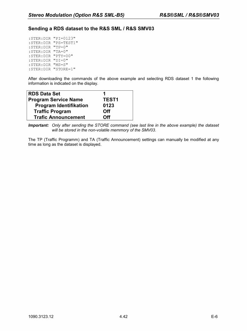
Stereo Modulation (Option R&S SML-B5) R&S®SML / R&S®SMV03
1090.3123.12 E-6 4.42
Sending a RDS dataset to the R&S SML / R&S SMV03
:STER:DIR "PI=0123" :STER:DIR "PS=TEST1" :STER:DIR "TP=0" :STER:DIR "TA=0" :STER:DIR "PTY=00" :STER:DIR "DI=0" :STER:DIR "MS=S" :STER:DIR "STORE=1"
After downloading the commands of the above example and selecting RDS dataset 1 the following information is indicated on the display. RDS Data Set 1 Program Service Name TEST1 Program Identifikation 0123 Traffic Program Off Trafic Announcement Off Important: Only after sending the STORE command (see last line in the above example) the dataset
will be stored in the non-volatile memmory of the SMV03. The TP (Traffic Programm) and TA (Traffic Announcement) settings can manually be modified at any time as long as the dataset is displayed.
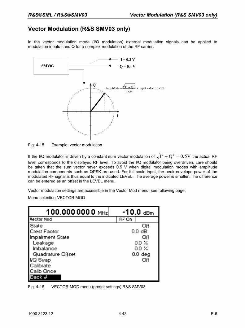
R&S®SML / R&S®SMV03 Vector Modulation (R&S SMV03 only)
1090.3123.12 E-6 4.43
Vector Modulation (R&S SMV03 only)
In the vector modulation mode (I/Q modulation) external modulation signals can be applied to modulation inputs I and Q for a complex modulation of the RF carrier.
I = 0.3 V
Q = 0.4 V
I
Q I QV
2 2
0 5+
,x input value LEVELAmplitude =
SMV03
Fig. 4-15 Example: vector modulation
If the I/Q modulator is driven by a constant sum vector modulation of I Q V2 2 0 5+ = . the actual RF level corresponds to the displayed RF level. To avoid the I/Q modulator being overdriven, care should be taken that the sum vector never exceeds 0.5 V when digital modulation modes with amplitude modulation components such as QPSK are used. For full-scale input, the peak envelope power of the modulated RF signal is thus equal to the indicated LEVEL. The average power is smaller. The difference can be entered as an offset in the LEVEL menu. Vector modulation settings are accessible in the Vector Mod menu, see following page.
Menu selection: VECTOR MOD
Fig. 4-16 VECTOR MOD menu (preset settings) R&S SMV03
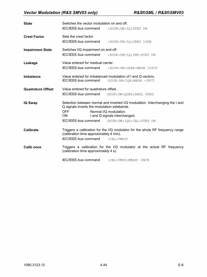
Vector Modulation (R&S SMV03 only) R&S®SML / R&S®SMV03
1090.3123.12 E-6 4.44
State Switches the vector modulation on and off. IEC/IEEE-bus command :SOUR:DM:IQ:STAT ON
Crest Factor
Sets the crest factor IEC/IEEE-bus command :SOUR:DM:IQ:CRES 10DB
Impairment State Switches I/Q impairment on and off. IEC/IEEE-bus command :SOUR:DM:IQ:IMP:STAT ON
Leakage Value entered for residual carrier . IEC/IEEE-bus command :SOUR:DM:LEAK:MAGN 10PCT
Imbalance Value entered for imbalanced modulation of I and Q vectors. IEC/IEEE-bus command :SOUR:DM:IQR:MAGN -5PCT
Quadrature Offset Value entered for quadrature offset . IEC/IEEE-bus command :SOUR:DM:QUAD:ANGL 4DEG
IQ Swap Selection between normal and inverted I/Q modulation. Interchanging the I and Q signals inverts the modulation sidebands. OFF Normal I/Q modulation. ON I and Q signals interchanged. IEC/IEEE-bus command :SOUR:DM:IQS:CAL:STAT ON
Calibrate Triggers a calibration for the I/Q modulator for the whole RF frequency range (calibration time approximately 4 min). IEC/IEEE-bus command :CAL:VMOD?
Calib once Triggers a calibration for the I/Q modulator at the actual RF frequency (calibration time approximately 4 s). IEC/IEEE-bus command :CAL:VMOD:MEAS? ONCE
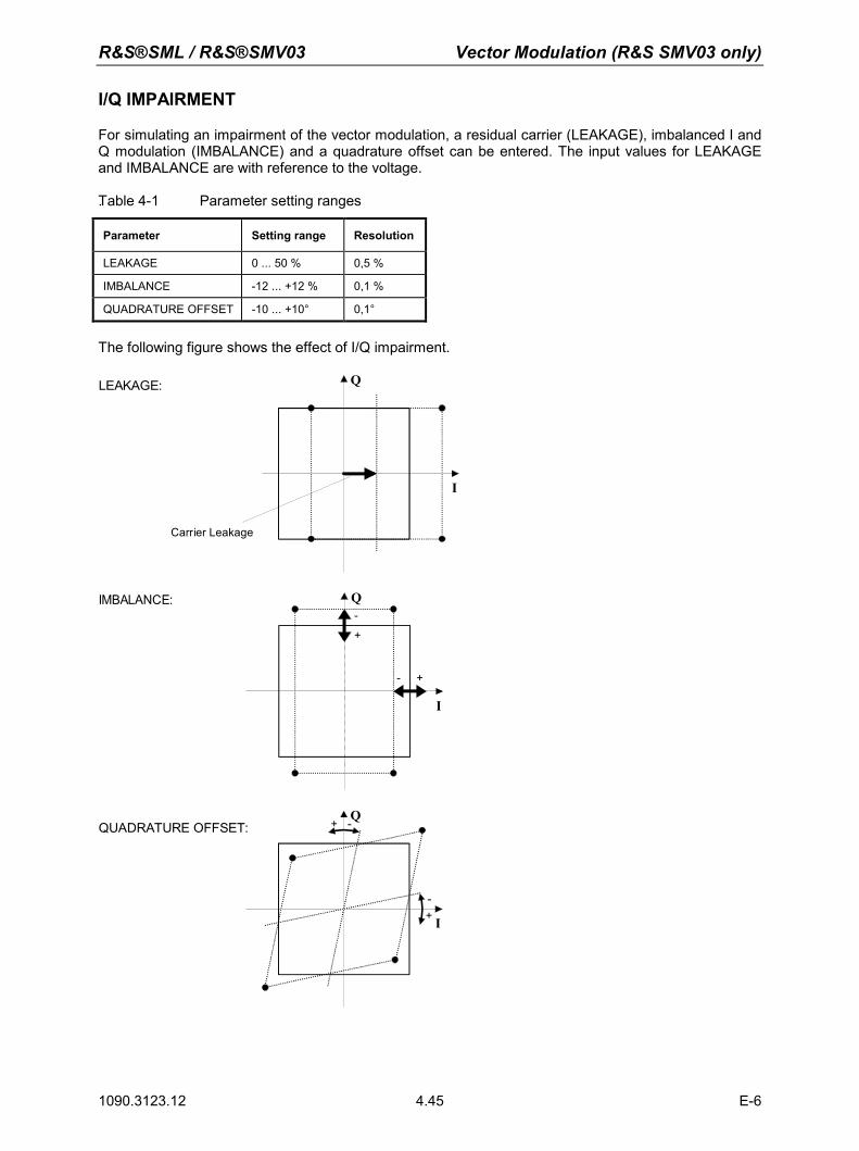
R&S®SML / R&S®SMV03 Vector Modulation (R&S SMV03 only)
1090.3123.12 E-6 4.45
I/Q IMPAIRMENT
For simulating an impairment of the vector modulation, a residual carrier (LEAKAGE), imbalanced I and Q modulation (IMBALANCE) and a quadrature offset can be entered. The input values for LEAKAGE and IMBALANCE are with reference to the voltage. .Table 4-1 Parameter setting ranges
Parameter Setting range Resolution
LEAKAGE 0 ... 50 % 0,5 %
IMBALANCE -12 ... +12 % 0,1 %
QUADRATURE OFFSET -10 ... +10° 0,1°
The following figure shows the effect of I/Q impairment.
I
Q
Carrier Leakage
LEAKAGE:
I
Q
+-
+
-IMBALANCE:
I
Q
+
+
-
-QUADRATURE OFFSET:
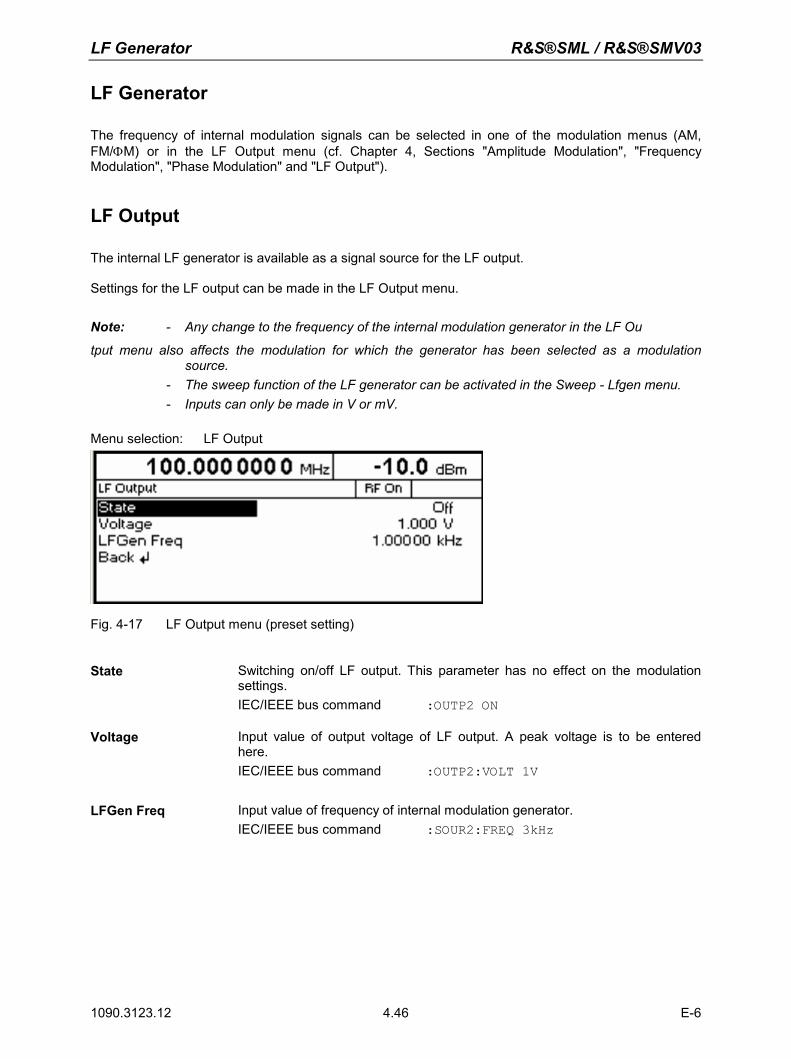
LF Generator R&S®SML / R&S®SMV03
1090.3123.12 E-6 4.46
LF Generator
The frequency of internal modulation signals can be selected in one of the modulation menus (AM, FM/ΦM) or in the LF Output menu (cf. Chapter 4, Sections "Amplitude Modulation", "Frequency Modulation", "Phase Modulation" and "LF Output").
LF Output
The internal LF generator is available as a signal source for the LF output. Settings for the LF output can be made in the LF Output menu.
Note: - Any change to the frequency of the internal modulation generator in the LF Ou
tput menu also affects the modulation for which the generator has been selected as a modulation source.
- The sweep function of the LF generator can be activated in the Sweep - Lfgen menu. - Inputs can only be made in V or mV. Menu selection: LF Output
Fig. 4-17 LF Output menu (preset setting)
State Switching on/off LF output. This parameter has no effect on the modulation
settings. IEC/IEEE bus command :OUTP2 ON
Voltage Input value of output voltage of LF output. A peak voltage is to be entered here. IEC/IEEE bus command :OUTP2:VOLT 1V
LFGen Freq Input value of frequency of internal modulation generator. IEC/IEEE bus command :SOUR2:FREQ 3kHz
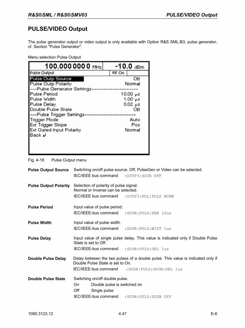
R&S®SML / R&S®SMV03 PULSE/VIDEO Output
1090.3123.12 E-6 4.47
PULSE/VIDEO Output
The pulse generator output or video output is only available with Option R&S SML-B3, pulse generator, cf. Section "Pulse Generator". Menu selection: Pulse Output
Fig. 4-18 Pulse Output menu
Pulse Output Source Switching on/off pulse source. Off, PulseGen or Video can be selected. IEC/IEEE bus command :OUTP3:SOUR OFF
Pulse Output Polarity Selection of polarity of pulse signal. Normal or Inverse can be selected. IEC/IEEE bus command :OUTP3:POL:PULS NORM
Pulse Period Input value of pulse period. IEC/IEEE-bus command :SOUR:PULS:PER 10us
Pulse Width Input value of pulse width. IEC/IEEE-bus command :SOUR:PULS:WIDT 1us
Pulse Delay Input value of single pulse delay. This value is indicated only if Double Pulse State is set to Off. IEC/IEEE-bus command :SOUR:PULS:DEL 1us
Double Pulse Delay Delay between the two pulses of a double pulse. This value is indicated only if Double Pulse State is set to On. IEC/IEEE-bus command :SOUR:PULS:DOUB:DEL 1us
Double Pulse State Switching on/off double pulse. On Double pulse is switched on Off Single pulse IEC/IEEE-bus command :SOUR:PULS:DOUB OFF
PULSE/VIDEO Output R&S®SML / R&S®SMV03
1090.3123.12 E-6 4.48
Trigger Mode Selection of trigger mode. Auto The pulse generator is triggered automatically. The pulse period is
as entered under Pulse Period. Single The pulse generator is triggered manually. The pulse period is
determined by the user. Ext Single The pulse generator is externally triggered. The pulse
period is determined by an external signal at the PULSE input. Ext Gated The pulse generator is triggered if the gate signal is active. IEC/IEEE-bus command :TRIG:PULS:SOUR AUTO
Execute Single Pulse Starts a single pulse. This function is displayed and is effective only if Single Mode is selected. IEC/IEEE-bus command :TRIG:PULS:IMM
Ext Trigger Slope Selection of active edge of external trigger signal. Pos The pulse generator is triggered on the positive edge of the
external signal. Neg The pulse generator is triggered on the negative edge of the
external signal. IEC/IEEE-bus command :TRIG:PULS:SLOP POS
Ext Gated Input Polarity
Definition of active level of gate signal (HIGH or LOW). Normal (HIGH) and Inverse (LOW) are available. IEC/IEEE-bus command :TRIG:PULS:EGAT:POL NORM
R&S®SML / R&S®SMV03 Sweep
1090.3123.12 E-6 4.49
Sweep
The R&S SML /R&S SMV03 features digital, step-by-step sweep for the following parameters: RF frequency
LF frequency
RF level
A sweep is set in four basic steps, which are demonstrated by the following example, ie the setting of a frequency sweep:
1. Set sweep range (Start Freq and Stop Freq or Center Freq and Span).
2. Select linear or logarithmic sweep (Spacing).
3. Select step size (Step Lin or Step Log) and dwell time (Dwell).
4. Switch on sweep (Mode set to Auto, Single, Step, Ext Single or Ext Step).
Setting the Sweep Range (Start Freq, Stop Freq, Center Freq, Span)
The sweep range for RF sweeps can be entered in two ways. Either the Start Freq and Stop Freq are entered or Center Freq and Span. Please note that the two parameter sets mutually affect each other as follows: Start Freq altered: Stop Freq = unaltered
Center Freq = (Start Freq + Stop Freq)/2 Span = (Stop Freq – Start Freq)
Stop Freq altered: Start Freq = unaltered Center Freq = (Start Freq + Stop Freq)/2 Span = (Stop Freq – Start Freq)
Center Freq altered: Span = unaltered Start Freq = (Center Freq – Span/2) Stop Freq = (Center Freq + Span/2)
Span altered: Center Freq = unaltered Start Freq = (Center Freq – Span/2) Stop Freq = (Center Freq + Span/2)
Sweep R&S®SML / R&S®SMV03
1090.3123.12 E-6 4.50
Selecting Linear or Logarithmic Sweep (Spacing Lin, Log)
Linear or logarithmic sweep can be selected with Spacing. For RF and LF sweeps, both the linear and logarithmic modes are selectable. For level sweeps, only the logarithmic mode is possible. With logarithmic sweeps, the step size (Step) is equal to a constant fraction of the current setting. The logarithmic step size for RF and LF sweeps is entered in % and for level sweeps in dB.
Operating Modes (Mode)
The following sweep modes are available: Auto Sweep from start point to stop point with automatic restart at start point. If another
sweep mode was active prior to selection of the auto mode, the sweep is continued from the setting active at that time. IEC/IEEE bus commands RF sweep: LF sweep: Level sweep: SOUR:FREQ:MODE SWE SOUR2:FREQ:MODE SWE SOUR:POW:MODE SWE SOUR:SWE:MODE AUTO SOUR2:SWE:MODE AUTO SOUR:SWE:POW:MODE AUTO TRIG:SOUR AUTO TRIG2:SOUR AUTO TRIG:SOUR AUTO
Single Single sweep from start point to stop point. The selection of Single does not start a sweep run. The sweep run is started by means of the Execute Single Sweep function, which is displayed below the Mode line. IEC/IEEE bus commands RF sweep: LF sweep: Level sweep: SOUR:FREQ:MODE SWE SOUR2:FREQ:MODE SWE SOUR:POW:MODE SWE SOUR:SWE:MODE AUTO SOUR2:SWE:MODE AUTO SOUR:SWE:POW:MODE AUTO TRIG:SOUR SING TRIG2:SOUR SING TRIG:SOUR SING
Step Step-by-step, manual run within the sweep limits. Activating Step stops a running sweep and the cursor moves to the value indicated for Current. The sweep can now be controlled upwards or downwards in discrete steps using the rotary knob or the numeric keys. IEC/IEEE-bus commands: RF sweep: LF sweep: Level sweep: SOUR:FREQ:MODE SWE SOUR2:FREQ:MODE SWE SOUR:POW:MODE SWE SOUR:SWE:MODE STEP SOUR2:SWE:MODE STEP SOUR:SWE:POW:MODE STEP TRIG:SOUR SING TRIG2:SOUR SING TRIG:SOUR SING
Ext Single Single sweep from start point to stop point as with Single, but triggered by an external signal IEC/IEEE-bus commands: RF sweep: LF sweep: Level sweep: SOUR:FREQ:MODE SWE SOUR2:FREQ:MODE SWE SOUR:POW:MODE SWE SOUR:SWE:MODE AUTO SOUR2:SWE:MODE AUTO SOUR:SWE:POW:MODE AUTO TRIG:SOUR EXT TRIG2:SOUR EXT TRIG:SOUR EXT
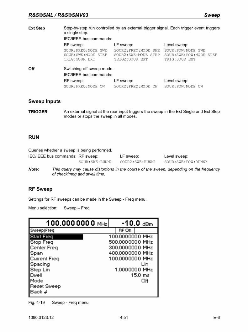
R&S®SML / R&S®SMV03 Sweep
1090.3123.12 E-6 4.51
Ext Step Step-by-step run controlled by an external trigger signal. Each trigger event triggers a single step. IEC/IEEE-bus commands: RF sweep: LF sweep: Level sweep: SOUR:FREQ:MODE SWE SOUR2:FREQ:MODE SWE SOUR:POW:MODE SWE SOUR:SWE:MODE STEP SOUR2:SWE:MODE STEP SOUR:SWE:POW:MODE STEP TRIG:SOUR EXT TRIG2:SOUR EXT TRIG:SOUR EXT
Off Switching-off sweep mode. IEC/IEEE-bus commands: RF sweep: LF sweep: Level sweep: SOUR:FREQ:MODE CW SOUR2:FREQ:MODE CW SOUR:POW:MODE CW
Sweep Inputs
TRIGGER An external signal at the rear input triggers the sweep in the Ext Single and Ext Step modes or stops the sweep in all modes.
RUN
Queries whether a sweep is being performed. IEC/IEEE bus commands: RF sweep: LF sweep: Level sweep: SOUR:SWE:RUNN? SOUR2:SWE:RUNN? SOUR:SWE:POW:RUNN?
Note: This query may cause distortions in the course of the sweep, depending on the frequency of checkimng and dwell time.
RF Sweep
Settings for RF sweeps can be made in the Sweep - Freq menu. Menu selection: Sweep – Freq
Fig. 4-19 Sweep - Freq menu
Sweep R&S®SML / R&S®SMV03
1090.3123.12 E-6 4.52
Start Freq Input value of start frequency. IEC/IEEE-bus command :SOUR:FREQ:STAR 100MHz
Stop Freq Input value of stop frequency. IEC/IEEE-bus command :SOUR:FREQ:STOP 500MHz
Center Freq Input value of center frequency. IEC/IEEE-bus command :SOUR:FREQ:CENT 300MHz
Span Input value of span. IEC/IEEE-bus command :SOUR:FREQ:SPAN 400MHz
Current Freq Display of current frequency value. In Step mode: input value of frequency.
Spacing Selection of linear or logarithmic sweep. IEC/IEEE-bus command :SOUR:SWE:SPAC LIN
Spacing Lin Input value of step size. Depending on whether Spacing Lin or Log is selected, Step Lin or Step Log is displayed. IEC/IEEE-bus command :SOUR:SWE:STEP:LIN 1MHz
Dwell Input value of dwell time per step. IEC/IEEE-bus command :SOUR:SWE:DWEL 15ms
Mode Selection of sweep mode. See section "Operating Modes". IEC/IEEE-bus commands :SOUR:FREQ:MODE SWE;
:SOUR:SWE:MODE AUTO; :TRIG:SOUR SING
Reset Sweep Resets the start frequency. IEC/IEEE-bus command :ABOR
Exec Single Sweep Starts a single sweep. This function is displayed and is effective only if Single Mode is selected. IEC/IEEE-bus command :TRIG
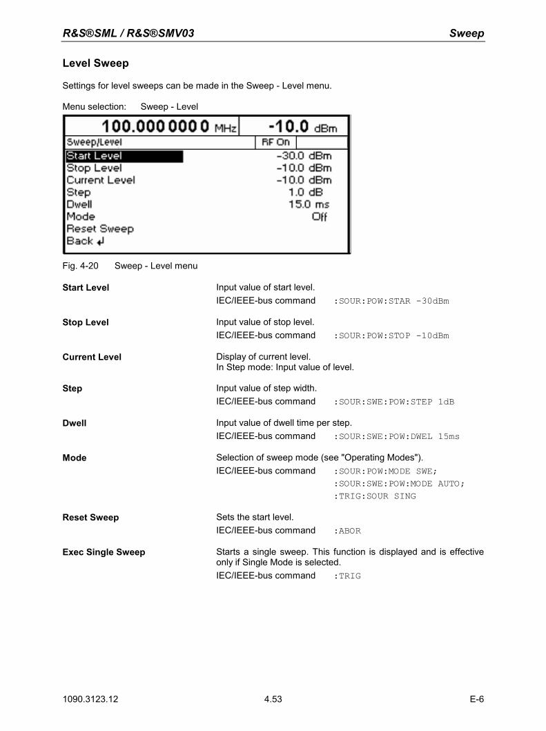
R&S®SML / R&S®SMV03 Sweep
1090.3123.12 E-6 4.53
Level Sweep
Settings for level sweeps can be made in the Sweep - Level menu. Menu selection: Sweep - Level
Fig. 4-20 Sweep - Level menu
Start Level Input value of start level. IEC/IEEE-bus command :SOUR:POW:STAR -30dBm
Stop Level Input value of stop level. IEC/IEEE-bus command :SOUR:POW:STOP -10dBm
Current Level Display of current level. In Step mode: Input value of level.
Step Input value of step width. IEC/IEEE-bus command :SOUR:SWE:POW:STEP 1dB
Dwell Input value of dwell time per step. IEC/IEEE-bus command :SOUR:SWE:POW:DWEL 15ms
Mode Selection of sweep mode (see "Operating Modes"). IEC/IEEE-bus command :SOUR:POW:MODE SWE; :SOUR:SWE:POW:MODE AUTO; :TRIG:SOUR SING
Reset Sweep Sets the start level. IEC/IEEE-bus command :ABOR
Exec Single Sweep Starts a single sweep. This function is displayed and is effective only if Single Mode is selected. IEC/IEEE-bus command :TRIG
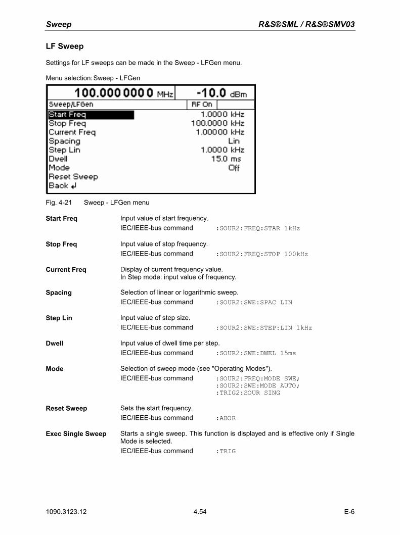
Sweep R&S®SML / R&S®SMV03
1090.3123.12 E-6 4.54
LF Sweep
Settings for LF sweeps can be made in the Sweep - LFGen menu. Menu selection: Sweep - LFGen
Fig. 4-21 Sweep - LFGen menu
Start Freq Input value of start frequency. IEC/IEEE-bus command :SOUR2:FREQ:STAR 1kHz
Stop Freq Input value of stop frequency. IEC/IEEE-bus command :SOUR2:FREQ:STOP 100kHz
Current Freq Display of current frequency value. In Step mode: input value of frequency.
Spacing Selection of linear or logarithmic sweep. IEC/IEEE-bus command :SOUR2:SWE:SPAC LIN
Step Lin Input value of step size. IEC/IEEE-bus command :SOUR2:SWE:STEP:LIN 1kHz
Dwell Input value of dwell time per step. IEC/IEEE-bus command :SOUR2:SWE:DWEL 15ms
Mode Selection of sweep mode (see "Operating Modes"). IEC/IEEE-bus command :SOUR2:FREQ:MODE SWE; :SOUR2:SWE:MODE AUTO; :TRIG2:SOUR SING
Reset Sweep Sets the start frequency. IEC/IEEE-bus command :ABOR
Exec Single Sweep Starts a single sweep. This function is displayed and is effective only if Single Mode is selected. IEC/IEEE-bus command :TRIG
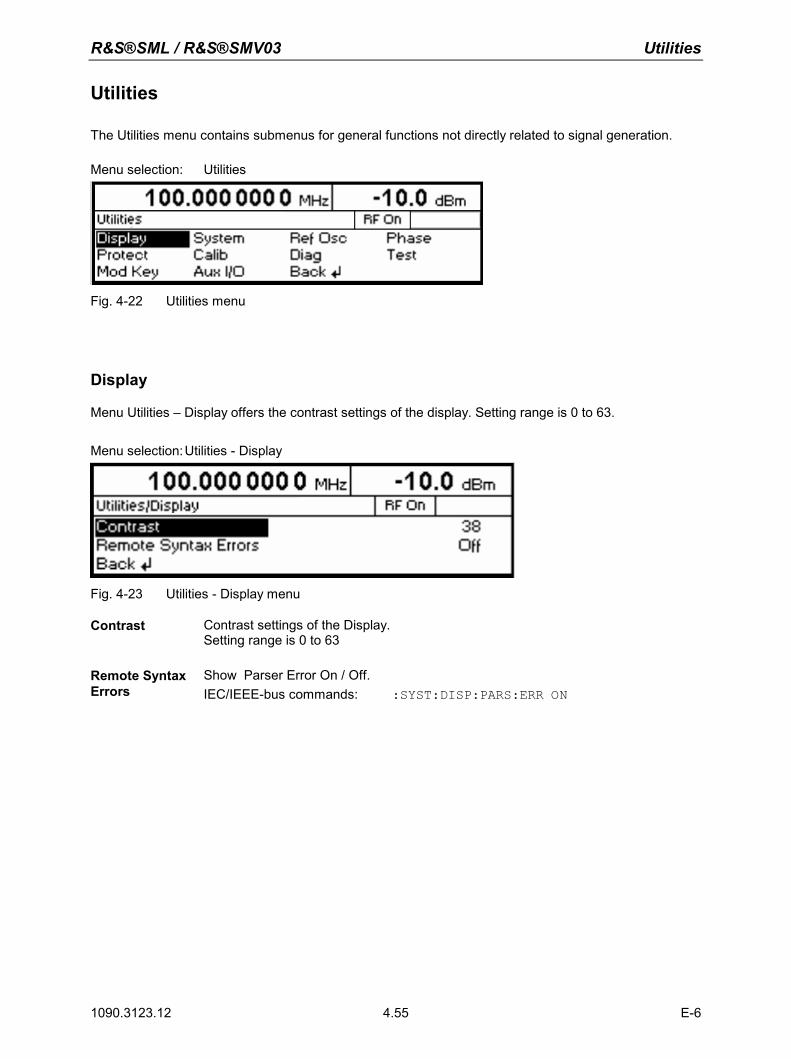
R&S®SML / R&S®SMV03 Utilities
1090.3123.12 E-6 4.55
Utilities
The Utilities menu contains submenus for general functions not directly related to signal generation. Menu selection: Utilities
Fig. 4-22 Utilities menu
Display
Menu Utilities – Display offers the contrast settings of the display. Setting range is 0 to 63.
Menu selection: Utilities - Display
Fig. 4-23 Utilities - Display menu
Contrast Contrast settings of the Display. Setting range is 0 to 63
Remote Syntax Errors
Show Parser Error On / Off. IEC/IEEE-bus commands: :SYST:DISP:PARS:ERR ON
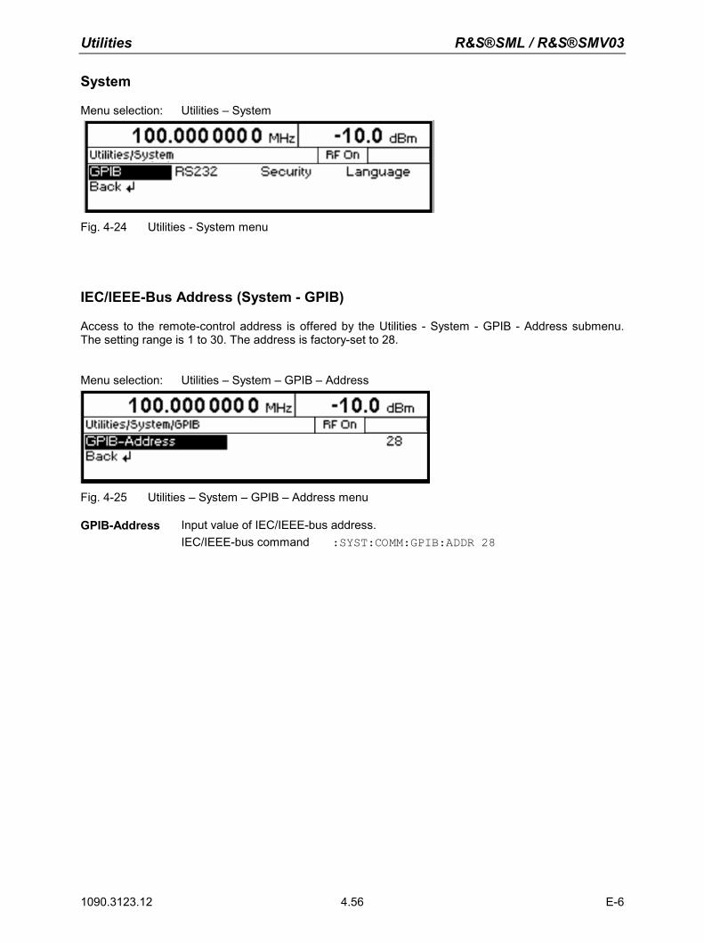
Utilities R&S®SML / R&S®SMV03
1090.3123.12 E-6 4.56
System
Menu selection: Utilities – System
Fig. 4-24 Utilities - System menu
IEC/IEEE-Bus Address (System - GPIB)
Access to the remote-control address is offered by the Utilities - System - GPIB - Address submenu. The setting range is 1 to 30. The address is factory-set to 28.
Menu selection: Utilities – System – GPIB – Address
Fig. 4-25 Utilities – System – GPIB – Address menu
GPIB-Address Input value of IEC/IEEE-bus address. IEC/IEEE-bus command :SYST:COMM:GPIB:ADDR 28
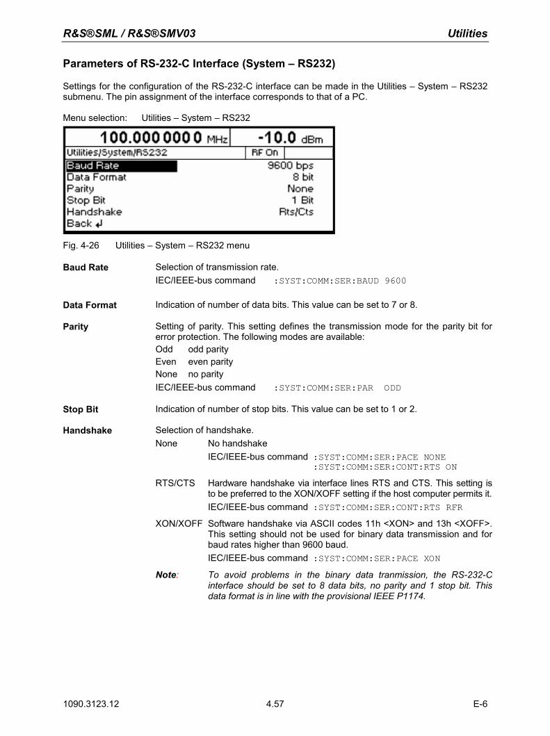
R&S®SML / R&S®SMV03 Utilities
1090.3123.12 E-6 4.57
Parameters of RS-232-C Interface (System – RS232)
Settings for the configuration of the RS-232-C interface can be made in the Utilities – System – RS232 submenu. The pin assignment of the interface corresponds to that of a PC. Menu selection: Utilities – System – RS232
Fig. 4-26 Utilities – System – RS232 menu
Baud Rate Selection of transmission rate. IEC/IEEE-bus command :SYST:COMM:SER:BAUD 9600
Data Format Indication of number of data bits. This value can be set to 7 or 8.
Parity Setting of parity. This setting defines the transmission mode for the parity bit for error protection. The following modes are available: Odd odd parity Even even parity None no parity IEC/IEEE-bus command :SYST:COMM:SER:PAR ODD
Stop Bit Indication of number of stop bits. This value can be set to 1 or 2.
Handshake Selection of handshake. None No handshake IEC/IEEE-bus command :SYST:COMM:SER:PACE NONE :SYST:COMM:SER:CONT:RTS ON
RTS/CTS Hardware handshake via interface lines RTS and CTS. This setting is to be preferred to the XON/XOFF setting if the host computer permits it.IEC/IEEE-bus command :SYST:COMM:SER:CONT:RTS RFR
XON/XOFF Software handshake via ASCII codes 11h <XON> and 13h <XOFF>. This setting should not be used for binary data transmission and for baud rates higher than 9600 baud.
IEC/IEEE-bus command :SYST:COMM:SER:PACE XON Note: To avoid problems in the binary data tranmission, the RS-232-C
interface should be set to 8 data bits, no parity and 1 stop bit. This data format is in line with the provisional IEEE P1174.
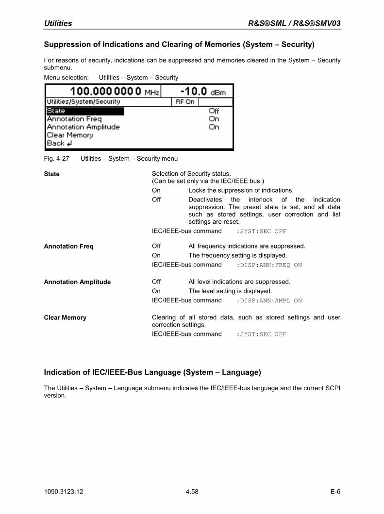
Utilities R&S®SML / R&S®SMV03
1090.3123.12 E-6 4.58
Suppression of Indications and Clearing of Memories (System – Security)
For reasons of security, indications can be suppressed and memories cleared in the System – Security submenu. Menu selection: Utilities – System – Security
Fig. 4-27 Utilities – System – Security menu
State Selection of Security status. (Can be set only via the IEC/IEEE bus.) On Locks the suppression of indications. Off Deactivates the interlock of the indication
suppression. The preset state is set, and all data such as stored settings, user correction and list settings are reset.
IEC/IEEE-bus command :SYST:SEC OFF
Annotation Freq Off All frequency indications are suppressed. On The frequency setting is displayed. IEC/IEEE-bus command :DISP:ANN:FREQ ON
Annotation Amplitude Off All level indications are suppressed. On The level setting is displayed. IEC/IEEE-bus command :DISP:ANN:AMPL ON
Clear Memory Clearing of all stored data, such as stored settings and user correction settings. IEC/IEEE-bus command :SYST:SEC OFF
Indication of IEC/IEEE-Bus Language (System – Language)
The Utilities – System – Language submenu indicates the IEC/IEEE-bus language and the current SCPI version.
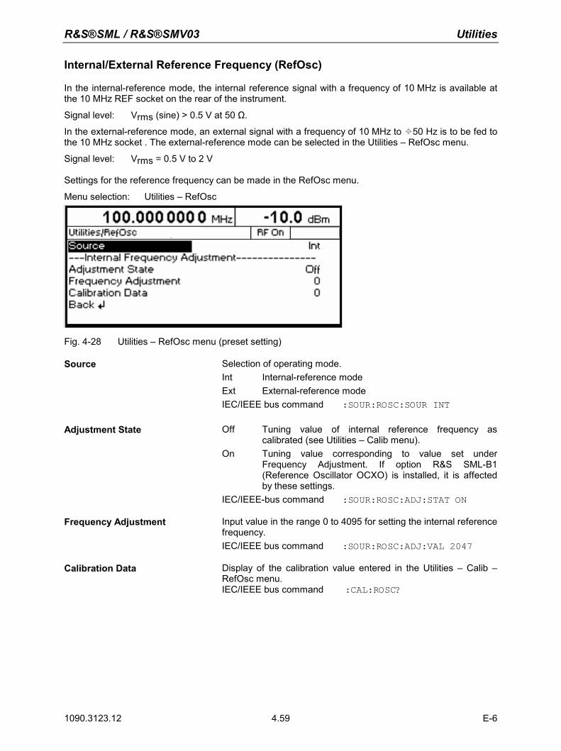
R&S®SML / R&S®SMV03 Utilities
1090.3123.12 E-6 4.59
Internal/External Reference Frequency (RefOsc)
In the internal-reference mode, the internal reference signal with a frequency of 10 MHz is available at the 10 MHz REF socket on the rear of the instrument. Signal level: Vrms (sine) > 0.5 V at 50 Ω.
In the external-reference mode, an external signal with a frequency of 10 MHz to 50 Hz is to be fed to the 10 MHz socket . The external-reference mode can be selected in the Utilities – RefOsc menu. Signal level: Vrms = 0.5 V to 2 V Settings for the reference frequency can be made in the RefOsc menu. Menu selection: Utilities – RefOsc
Fig. 4-28 Utilities – RefOsc menu (preset setting)
Source Selection of operating mode. Int Internal-reference mode Ext External-reference mode IEC/IEEE bus command :SOUR:ROSC:SOUR INT
Adjustment State Off Tuning value of internal reference frequency as calibrated (see Utilities – Calib menu).
On Tuning value corresponding to value set under Frequency Adjustment. If option R&S SML-B1 (Reference Oscillator OCXO) is installed, it is affected by these settings.
IEC/IEEE-bus command :SOUR:ROSC:ADJ:STAT ON
Frequency Adjustment Input value in the range 0 to 4095 for setting the internal reference frequency. IEC/IEEE bus command :SOUR:ROSC:ADJ:VAL 2047
Calibration Data Display of the calibration value entered in the Utilities – Calib – RefOsc menu. IEC/IEEE bus command :CAL:ROSC?
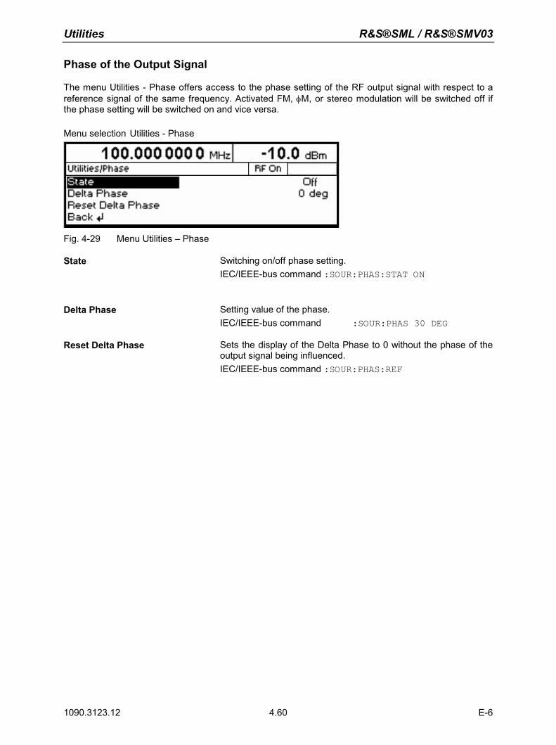
Utilities R&S®SML / R&S®SMV03
1090.3123.12 E-6 4.60
Phase of the Output Signal
The menu Utilities - Phase offers access to the phase setting of the RF output signal with respect to a reference signal of the same frequency. Activated FM, φM, or stereo modulation will be switched off if the phase setting will be switched on and vice versa. Menu selection Utilities - Phase
Fig. 4-29 Menu Utilities – Phase
State Switching on/off phase setting. IEC/IEEE-bus command :SOUR:PHAS:STAT ON
Delta Phase Setting value of the phase. IEC/IEEE-bus command :SOUR:PHAS 30 DEG
Reset Delta Phase Sets the display of the Delta Phase to 0 without the phase of the output signal being influenced. IEC/IEEE-bus command :SOUR:PHAS:REF
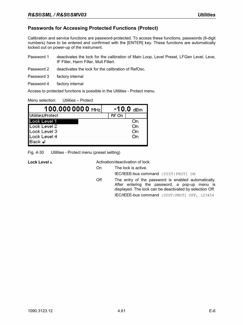
R&S®SML / R&S®SMV03 Utilities
1090.3123.12 E-6 4.61
Passwords for Accessing Protected Functions (Protect)
Calibration and service functions are password-protected. To access these functions, passwords (6-digit numbers) have to be entered and confirmed with the [ENTER] key. These functions are automatically locked out on power-up of the instrument. Password 1 deactivates the lock for the calibration of Main Loop, Level Preset, LFGen Level, Leve,
IF Filter, Harm Filter, Mult Filterl.
Password 2 deactivates the lock for the calibration of RefOsc.
Password 3 factory internal
Password 4 factory internal
Access to protected functions is possible in the Utilities - Protect menu. Menu selection: Utilities – Protect
Fig. 4-30 Utilities - Protect menu (preset setting)
Lock Level x Activation/deactivation of lock. On The lock is active.
IEC/IEEE-bus command :SYST:PROT1 ON Off The entry of the password is enabled automatically.
After entering the password, a pop-up menu is displayed. The lock can be deactivated by selection Off. IEC/IEEE-bus command :SYST:PROT1 OFF, 123456
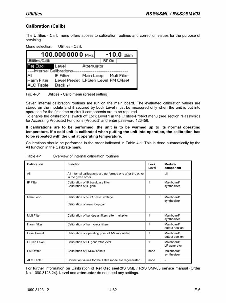
Utilities R&S®SML / R&S®SMV03
1090.3123.12 E-6 4.62
Calibration (Calib)
The Utilities - Calib menu offers access to calibration routines and correction values for the purpose of servicing. Menu selection: Utilities - Calib
Fig. 4-31 Utilities - Calib menu (preset setting)
Seven internal calibration routines are run on the main board. The evaluated calibration values are stored on the module and if secured by Lock Level must be measured only when the unit is put into operation for the first time or circuit components are to be repaired. To enable the calibrations, switch off Lock Level 1 in the Utilities-Protect menu (see section "Passwords for Accessing Protected Functions (Protect)” and enter password 123456. If calibrations are to be performed, the unit is to be warmed up to its normal operating temperature. If a cold unit is calibrated when putting the unit into operation, the calibration has to be repeated with the unit at operating temperature. Calibrations should be performed in the order indicated in Table 4-1. This is done automatically by the All function in the Calibrate menu.
Table 4-1 Overview of internal calibration routines
Calibration Function Lock Level
Module/ component
All All internal calibrations are performed one after the other in the given order.
all
IF Filter Calibration of IF bandpass filter Calibration of IF gain
1 Mainboard/ synthesizer
Main Loop Calibration of VCO preset voltage Calibration of main loop gain
1 Mainboard/ synthesizer
Mult Filter Calibration of bandpass filters after multiplier 1 Mainboard/ synthesizer
Harm Filter Calibration of harmonics filters 1 Mainboard/ output section
Level Preset Calibration of operating point of AM modulator 1 Mainboard/ output section
LFGen Level Calibration of LF generator level 1 Mainboard/ LF generator
FM Offset Calibration of FMDC offsets none Mainboard/ synthesizer
ALC Table Correction values for the Table mode are regenerated. none -
For further information on Calibration of Ref Osc seeR&S SML / R&S SMV03 service manual (Order No. 1090.3123.24). Level and attenuator do not need any settings.
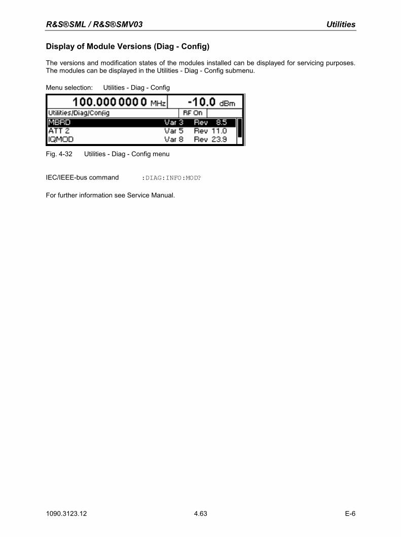
R&S®SML / R&S®SMV03 Utilities
1090.3123.12 E-6 4.63
Display of Module Versions (Diag - Config)
The versions and modification states of the modules installed can be displayed for servicing purposes. The modules can be displayed in the Utilities - Diag - Config submenu. Menu selection: Utilities - Diag - Config
Fig. 4-32 Utilities - Diag - Config menu
IEC/IEEE-bus command :DIAG:INFO:MOD? For further information see Service Manual.
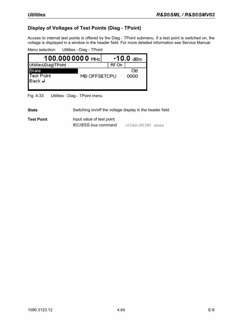
Utilities R&S®SML / R&S®SMV03
1090.3123.12 E-6 4.64
Display of Voltages of Test Points (Diag - TPoint)
Access to internal test points is offered by the Diag - TPoint submenu. If a test point is switched on, the voltage is displayed in a window in the header field. For more detailed information see Service Manual.
Menu selection: Utilities - Diag - TPoint
Fig. 4-33 Utilities - Diag - TPoint menu
State Switching on/off the voltage display in the header field.
Test Point Input value of test point.
IEC/IEEE-bus command :DIAG:POIN? xxxx
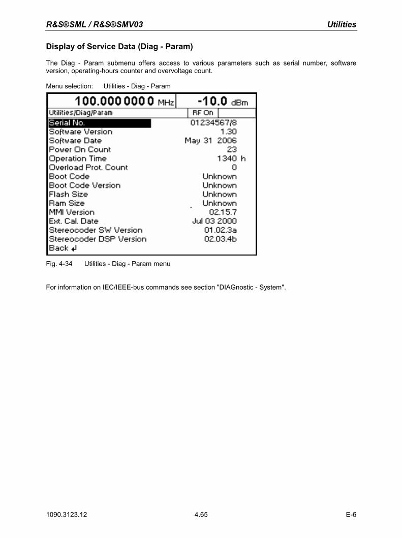
R&S®SML / R&S®SMV03 Utilities
1090.3123.12 E-6 4.65
Display of Service Data (Diag - Param)
The Diag - Param submenu offers access to various parameters such as serial number, software version, operating-hours counter and overvoltage count. Menu selection: Utilities - Diag - Param
Fig. 4-34 Utilities - Diag - Param menu
For information on IEC/IEEE-bus commands see section "DIAGnostic - System".
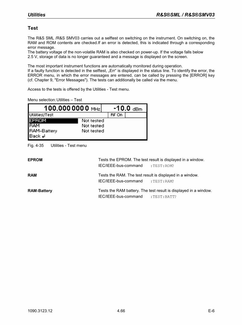
Utilities R&S®SML / R&S®SMV03
1090.3123.12 E-6 4.66
Test
The R&S SML /R&S SMV03 carries out a selftest on switching on the instrument. On switching on, the RAM and ROM contents are checked.If an error is detected, this is indicated through a corresponding error message. The battery voltage of the non-volatile RAM is also checked on power-up. If the voltage falls below 2.5 V, storage of data is no longer guaranteed and a message is displayed on the screen. The most important instrument functions are automatically monitored during operation. If a faulty function is detected in the selftest, „Err“ is displayed in the status line. To identify the error, the ERROR menu, in which the error messages are entered, can be called by pressing the [ERROR] key (cf. Chapter 9, "Error Messages"). The tests can additionally be called via the menu. Access to the tests is offered by the Utilities - Test menu. Menu selection: Utilities – Test
Fig. 4-35 Utilities - Test menu
EPROM Tests the EPROM. The test result is displayed in a window.
IEC/IEEE-bus-command :TEST:ROM?
RAM Tests the RAM. The test result is displayed in a window. IEC/IEEE-bus-command :TEST:RAM?
RAM-Battery Tests the RAM battery. The test result is displayed in a window. IEC/IEEE-bus-command :TEST:BATT?
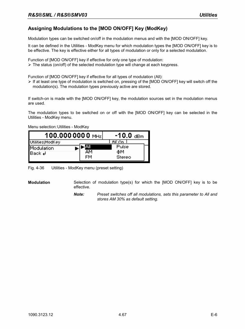
R&S®SML / R&S®SMV03 Utilities
1090.3123.12 E-6 4.67
Assigning Modulations to the [MOD ON/OFF] Key (ModKey)
Modulation types can be switched on/off in the modulation menus and with the [MOD ON/OFF] key. It can be defined in the Utilities - ModKey menu for which modulation types the [MOD ON/OFF] key is to be effective. The key is effective either for all types of modulation or only for a selected modulation. Function of [MOD ON/OFF] key if effective for only one type of modulation: The status (on/off) of the selected modulation type will change at each keypress.
Function of [MOD ON/OFF] key if effective for all types of modulation (All): If at least one type of modulation is switched on, pressing of the [MOD ON/OFF] key will switch off the
modulation(s). The modulation types previously active are stored.
If switch-on is made with the [MOD ON/OFF] key, the modulation sources set in the modulation menus are used. The modulation types to be switched on or off with the [MOD ON/OFF] key can be selected in the Utilities - ModKey menu. Menu selection: Utilities - ModKey
Fig. 4-36 Utilities - ModKey menu (preset setting)
Modulation Selection of modulation type(s) for which the [MOD ON/OFF] key is to be
effective.
Note: Preset switches off all modulations, sets this parameter to All and stores AM 30% as default setting.
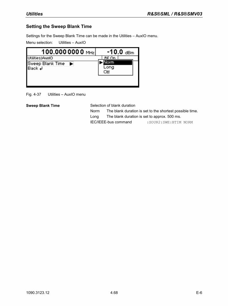
Utilities R&S®SML / R&S®SMV03
1090.3123.12 E-6 4.68
Setting the Sweep Blank Time
Settings for the Sweep Blank Time can be made in the Utilities – AuxIO menu.
Menu selection: Utilities – AuxIO
Fig. 4-37 Utilities – AuxIO menu
Sweep Blank Time Selection of blank duration
Norm The blank duration is set to the shortest possible time. Long The blank duration is set to approx. 500 ms. IEC/IEEE-bus command :SOUR2:SWE:BTIM NORM
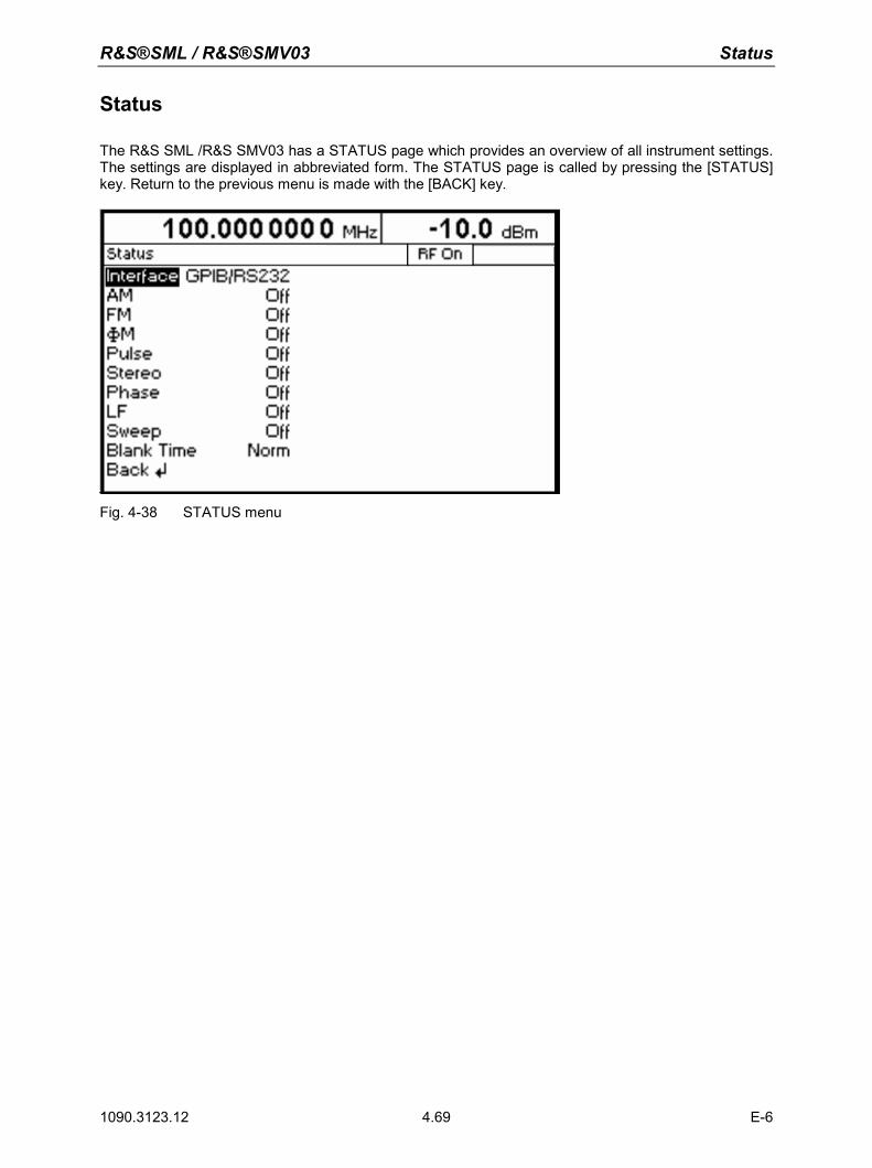
R&S®SML / R&S®SMV03 Status
1090.3123.12 E-6 4.69
Status
The R&S SML /R&S SMV03 has a STATUS page which provides an overview of all instrument settings. The settings are displayed in abbreviated form. The STATUS page is called by pressing the [STATUS] key. Return to the previous menu is made with the [BACK] key.
Fig. 4-38 STATUS menu

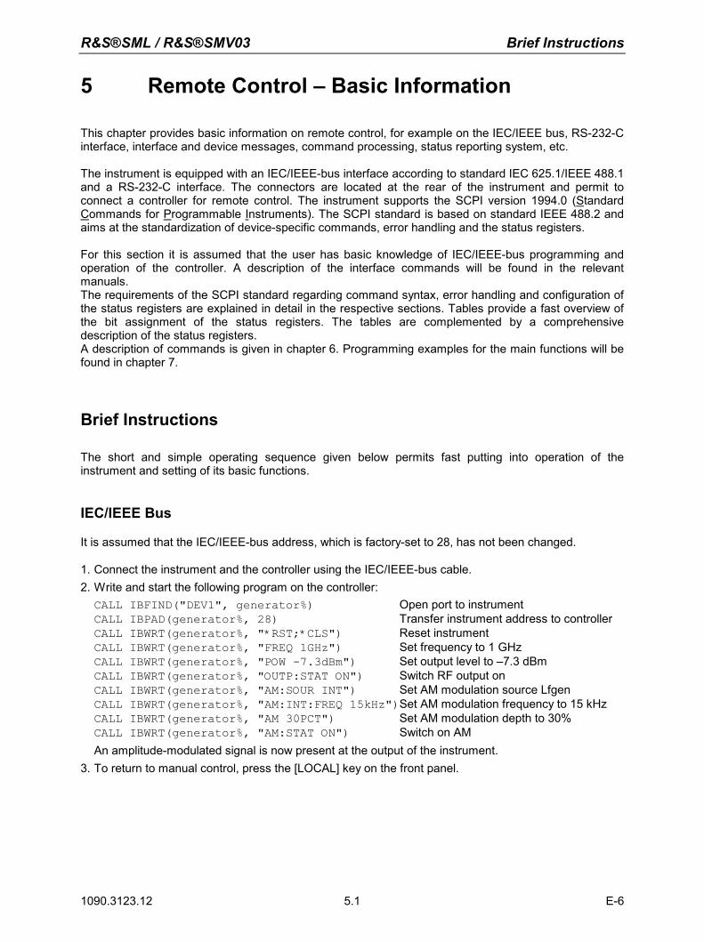
R&S®SML / R&S®SMV03 Brief Instructions
1090.3123.12 E-6 5.1
5 Remote Control – Basic Information
This chapter provides basic information on remote control, for example on the IEC/IEEE bus, RS-232-C interface, interface and device messages, command processing, status reporting system, etc. The instrument is equipped with an IEC/IEEE-bus interface according to standard IEC 625.1/IEEE 488.1 and a RS-232-C interface. The connectors are located at the rear of the instrument and permit to connect a controller for remote control. The instrument supports the SCPI version 1994.0 (Standard Commands for Programmable Instruments). The SCPI standard is based on standard IEEE 488.2 and aims at the standardization of device-specific commands, error handling and the status registers. For this section it is assumed that the user has basic knowledge of IEC/IEEE-bus programming and operation of the controller. A description of the interface commands will be found in the relevant manuals. The requirements of the SCPI standard regarding command syntax, error handling and configuration of the status registers are explained in detail in the respective sections. Tables provide a fast overview of the bit assignment of the status registers. The tables are complemented by a comprehensive description of the status registers. A description of commands is given in chapter 6. Programming examples for the main functions will be found in chapter 7.
Brief Instructions
The short and simple operating sequence given below permits fast putting into operation of the instrument and setting of its basic functions.
IEC/IEEE Bus
It is assumed that the IEC/IEEE-bus address, which is factory-set to 28, has not been changed. 1. Connect the instrument and the controller using the IEC/IEEE-bus cable. 2. Write and start the following program on the controller: CALL IBFIND("DEV1", generator%) Open port to instrument CALL IBPAD(generator%, 28) Transfer instrument address to controller CALL IBWRT(generator%, "*RST;*CLS") Reset instrument CALL IBWRT(generator%, "FREQ 1GHz") Set frequency to 1 GHz CALL IBWRT(generator%, "POW -7.3dBm") Set output level to –7.3 dBm CALL IBWRT(generator%, "OUTP:STAT ON") Switch RF output on CALL IBWRT(generator%, "AM:SOUR INT") Set AM modulation source Lfgen CALL IBWRT(generator%, "AM:INT:FREQ 15kHz")Set AM modulation frequency to 15 kHz CALL IBWRT(generator%, "AM 30PCT") Set AM modulation depth to 30% CALL IBWRT(generator%, "AM:STAT ON") Switch on AM An amplitude-modulated signal is now present at the output of the instrument. 3. To return to manual control, press the [LOCAL] key on the front panel.
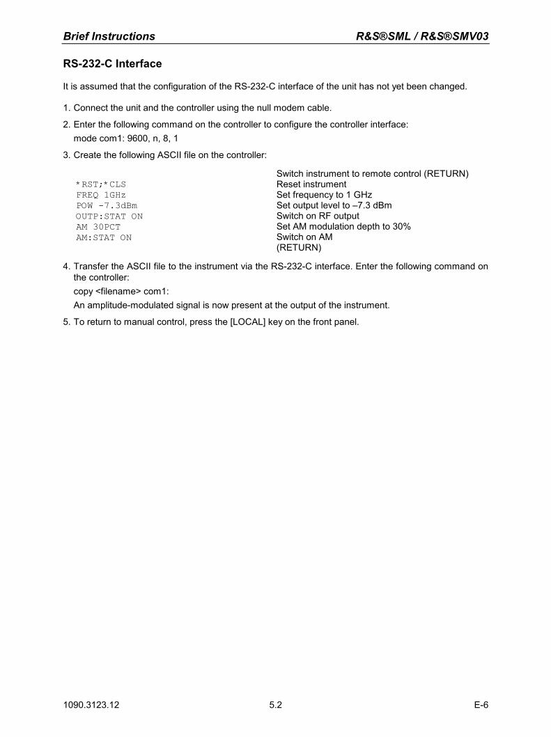
Brief Instructions R&S®SML / R&S®SMV03
1090.3123.12 E-6 5.2
RS-232-C Interface
It is assumed that the configuration of the RS-232-C interface of the unit has not yet been changed. 1. Connect the unit and the controller using the null modem cable.
2. Enter the following command on the controller to configure the controller interface: mode com1: 9600, n, 8, 1
3. Create the following ASCII file on the controller:
*RST;*CLS FREQ 1GHz POW -7.3dBm OUTP:STAT ON AM 30PCT AM:STAT ON
Switch instrument to remote control (RETURN) Reset instrument Set frequency to 1 GHz Set output level to –7.3 dBm Switch on RF output Set AM modulation depth to 30% Switch on AM (RETURN)
4. Transfer the ASCII file to the instrument via the RS-232-C interface. Enter the following command on the controller:
copy <filename> com1: An amplitude-modulated signal is now present at the output of the instrument.
5. To return to manual control, press the [LOCAL] key on the front panel.
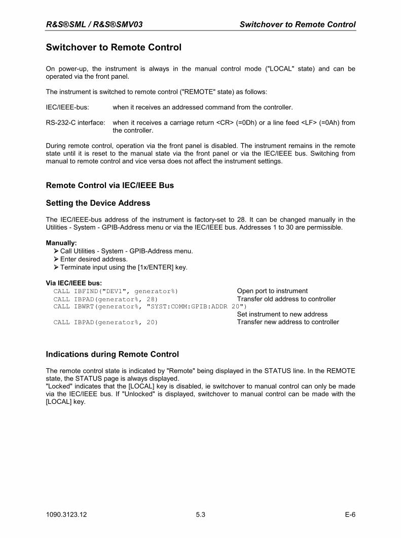
R&S®SML / R&S®SMV03 Switchover to Remote Control
1090.3123.12 E-6 5.3
Switchover to Remote Control
On power-up, the instrument is always in the manual control mode ("LOCAL" state) and can be operated via the front panel. The instrument is switched to remote control ("REMOTE" state) as follows: IEC/IEEE-bus: when it receives an addressed command from the controller. RS-232-C interface: when it receives a carriage return <CR> (=0Dh) or a line feed <LF> (=0Ah) from
the controller. During remote control, operation via the front panel is disabled. The instrument remains in the remote state until it is reset to the manual state via the front panel or via the IEC/IEEE bus. Switching from manual to remote control and vice versa does not affect the instrument settings.
Remote Control via IEC/IEEE Bus
Setting the Device Address
The IEC/IEEE-bus address of the instrument is factory-set to 28. It can be changed manually in the Utilities - System - GPIB-Address menu or via the IEC/IEEE bus. Addresses 1 to 30 are permissible. Manually: Call Utilities - System - GPIB-Address menu. Enter desired address. Terminate input using the [1x/ENTER] key. Via IEC/IEEE bus: CALL IBFIND("DEV1", generator%) Open port to instrument CALL IBPAD(generator%, 28) Transfer old address to controller CALL IBWRT(generator%, "SYST:COMM:GPIB:ADDR 20") Set instrument to new address CALL IBPAD(generator%, 20) Transfer new address to controller
Indications during Remote Control
The remote control state is indicated by "Remote" being displayed in the STATUS line. In the REMOTE state, the STATUS page is always displayed. "Locked" indicates that the [LOCAL] key is disabled, ie switchover to manual control can only be made via the IEC/IEEE bus. If "Unlocked" is displayed, switchover to manual control can be made with the [LOCAL] key.
Switchover to Remote Control R&S®SML / R&S®SMV03
1090.3123.12 E-6 5.4
Return to Manual Operation
Return to manual operation can be made via the front panel or the IEC/IEEE bus.
Manually: Press [LOCAL] key.
Note: – Before switchover, command processing must be completed as otherwise
switchover to remote control is effected immediately. – The [LOCAL] key can be disabled by the universal command LLO in order to
prevent unintentional switchover. In this case, switchover to manual control is only possible via the IEC/IEEE bus.
– The [LOCAL] key can be enabled again by deactivating the REN control line of the IEC/IEEE bus.
Via IEC/IEEE bus: ...
CALL IBLOC(generator%) Set instrument to manual control ...
Remote Control via RS-232-C Interface
Setting the Transmission Parameters
To enable error-free and correct data transmission, the parameters of the instrument and the controller should have the same setting. To prevent any problems during binary data transmission, the RS-232-C interface should be set to 8 data bits, “No parity” and 1 stop bit. This data format corresponds to the IEEE P1174 draft standard. The baud rate and handshake can be manually changed in the Utilities - System - RS232 menu.
Call Utilities – System - RS232 menu.
Select desired baud rate and handshake.
Terminate input using the [1x/ENTER] key.
Indications during Remote Control
The remote control state is indicated by "Remote" in the STATUS line. In the REMOTE state, the STATUS page is always displayed.
Return to Manual Operation
Return to manual operation can be made via the front panel.
Press [LOCAL] key.
Note: Before switchover, command processing must be completed as otherwise switchover to remote control is effected immediately.
R&S®SML / R&S®SMV03 Messages
1090.3123.12 E-6 5.5
Messages
The messages transferred via the data lines of the IEC/IEEE bus can be divided into two groups: – interfaces messages and – device messages No interface messages are defined for the RS-232-C interface.
Interface Messages
Interface messages are transferred on the data lines of the IEC/IEEE bus, the ATN control line being active. They are used for communication between the controller and the instrument and can only be sent by a controller which has the IEC/IEEE-bus control. Interface commands can be subdivided into
- universal commands and - addressed commands
Universal commands act on all devices connected to the IEC/IEEE bus without previous addressing, addressed commands only act on devices previously addressed as listeners. The interface messages relevant to the instrument are listed in the section "Interface Messages" below. Some control characters are defined for the control of the RS-232-C interface, see section "Interface Functions".
Device Messages (Commands and Device Responses) Device messages are transferred on the data lines of the IEC/IEEE bus, the ATN control line not being active. ASCII code is used. The device messages are largely identical for the two interfaces (IEC/IEEE bus and RS-232-C). A distinction is made according to the direction in which device messages are sent on the IEC/IEEE bus: – Commands are messages the controller sends to the instrument.
They operate the device functions and request information. Commands are subdivided according to two criteria:
1. According to the effect they have on the instrument:
Setting commands cause instrument settings such as reset of the instrument or setting the output level to 1 V.
Queries cause data to be provided for output (queries) on the
IEC/IEEE bus, eg for device identification or polling of the active input.
2. According to their definition in standard IEEE 488.2:
Common Commands are exactly defined as to their function and notation in
standard IEEE 488.2. They refer to functions such as the management of the standardized status registers, reset and selftest.
Device-specific refer to functions depending on the features of the
commands instrument such as frequency setting. A majority of these commands has also been standardized by the SCPI committee.
– Device responses are messages the instruments sends to the controller in reply to a query. They
may contain measurement results or information on the instrument status. The structure and syntax of device messages are described in the following section.
Structure and Syntax of Device Messages R&S®SML / R&S®SMV03
1090.3123.12 E-6 5.6
Structure and Syntax of Device Messages
Introduction to SCPI
SCPI (Standard Commands for Programmable Instruments) describes a standard command set for programming instruments, irrespective of the type of instrument or manufacturer. The objective of the SCPI consortium is to standardize the device-specific commands to a large extent. For this purpose, a model was developed which defines identical functions of a device or of different devices. Command systems were generated which are assigned to these functions. Thus it is possible to address identical functions with identical commands. The command systems are of a hierarchical structure. Fig. 5-1 illustrates this tree structure using a section of command system SOURce, which operates the signal sources of the devices. The other examples concerning syntax and structure of the commands are derived from this command system. SCPI is based on standard IEEE 488.2, ie it uses the same basic syntax elements as well as the common commands defined in this standard. Part of the syntax of the device responses is defined in greater detail than in standard IEEE 488.2 (see section "Responses to Queries").
Structure of Commands
Commands consist of a header and, in most cases, one or several parameters. The header and the parameters are separated by a "white space" (ASCII code 0 to 9, 11 to 32 decimal, eg a blank). Headers may consist of several key words. Queries are formed by appending a question mark directly to the header. Note: The commands used in the following examples are not in every case implemented in the
instrument.
Common commands Common (device-independent) commands consist of a header preceded by an asterisk "*" and of one or several parameters, if any.
Examples: *RST RESET, resets the instrument *ESE 253 EVENT STATUS ENABLE, sets the bits of
the event status enable register *ESR? EVENT STATUS QUERY, queries the
contents of the event status register Device-specific commands The following examples are general, they are not necessarly available
with R&S SML / R&S SMV03.
Hierarchy: Device-specific commands are of a hierarchical structure (see Fig. 5-1). The different levels are represented by combined headers. Headers of the highest level (root level) have only one key word. This key word denotes a complete command system.
Example: SOURce
This key word denotes the SOURce command system.
For commands of lower levels, the complete path has to be specified, starting on the left with the highest level, the individual key words being separated by a colon ":".
Example: SOURce:FM:EXTernal:COUPling AC
This command is at the fourth level of the SOURce system. It selects AC coupling of the external signal source.
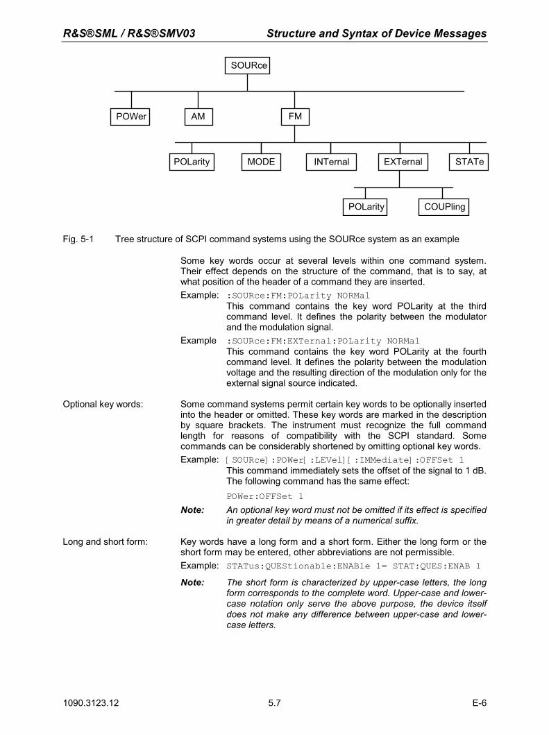
R&S®SML / R&S®SMV03 Structure and Syntax of Device Messages
1090.3123.12 E-6 5.7
SOURce
POWer AM FM
MODE INTernal EXTernal STATePOLarity
POLarity COUPling
Fig. 5-1 Tree structure of SCPI command systems using the SOURce system as an example
Some key words occur at several levels within one command system. Their effect depends on the structure of the command, that is to say, at what position of the header of a command they are inserted. Example: :SOURce:FM:POLarity NORMal
This command contains the key word POLarity at the third command level. It defines the polarity between the modulator and the modulation signal.
Example :SOURce:FM:EXTernal:POLarity NORMal This command contains the key word POLarity at the fourth command level. It defines the polarity between the modulation voltage and the resulting direction of the modulation only for the external signal source indicated.
Optional key words: Some command systems permit certain key words to be optionally inserted
into the header or omitted. These key words are marked in the description by square brackets. The instrument must recognize the full command length for reasons of compatibility with the SCPI standard. Some commands can be considerably shortened by omitting optional key words. Example: [SOURce]:POWer[:LEVel][:IMMediate]:OFFSet 1
This command immediately sets the offset of the signal to 1 dB. The following command has the same effect:
POWer:OFFSet 1 Note: An optional key word must not be omitted if its effect is specified
in greater detail by means of a numerical suffix. Long and short form: Key words have a long form and a short form. Either the long form or the
short form may be entered, other abbreviations are not permissible. Example: STATus:QUEStionable:ENABle 1= STAT:QUES:ENAB 1
Note: The short form is characterized by upper-case letters, the long form corresponds to the complete word. Upper-case and lower-case notation only serve the above purpose, the device itself does not make any difference between upper-case and lower-case letters.
Structure and Syntax of Device Messages R&S®SML / R&S®SMV03
1090.3123.12 E-6 5.8
Parameters: A parameter must be separated from the header by a "white space". If a command includes several parameters, they are separated by a comma ",". Some queries permit the parameters MINimum, MAXimum and DEFault to be entered. For a description of these parameter types see section "Parameters". Example: SOURce:POWer:ATTenuation? MAXimum Response: 60
This query requests the maximum value for the attenuation.
Numerical suffix: If a device has several functions or features of the same kind, eg inputs, the desired function can be selected by appending a suffix to the command. Entries without suffix are interpreted like entries with the suffix 1. Example: SOURce2:FREQuency:MODE CW
This command determines the operating mode for the Frequency Subsystem.
R&S®SML / R&S®SMV03 Structure and Syntax of Device Messages
1090.3123.12 E-6 5.9
Structure of Command Lines
A command line may contain one or several commands. It is terminated by <New Line>, <New Line> with EOI or EOI together with the last data byte. QuickBASIC automatically produces EOI together with the last data byte. Several commands in a command line are separated by a semicolon ";". If the next command belongs to a different command system, the semicolon is followed by a colon. Example: CALL IBWRT(generator%, "SOURce:POWer:CENTer MINimum;:OUTPut:ATTenuation 10")
This command line contains two commands. The first command belongs to the SOURce system and defines the center frequency of the output signal. The second command belongs to the OUTPut system and sets the attenuation of the output signal.
If successive commands belong to the same system and thus have one or several levels in common, the command line can be abbreviated. To this end, the second command (after the semicolon) is started with the level that lies below the common levels (see also Fig. 5-1). The colon following the semicolon must be omitted in this case. Example: CALL IBWRT(generator%, "SOURce:FM:MODE LOCKed;:SOURce:FM:INTernal:FREQuency 1kHz")
This command line is represented in its full length and contains two commands separated from each other by the semicolon. The two commands belong to the SOURce command system, subsystem FM, ie they have two common levels. To abbreviate the command line, the second command is started with the level below SOURce:FM. The colon after the semicolon is omitted. The abbreviated form of the command line reads as follows:
CALL IBWRT(generator%, "SOURce:FM:MODE LOCKed;INTernal:FREQuency 1kHz") However, a new command line always has to be started with the complete path. Example: CALL IBWRT(generator%, "SOURce:FM:MODE LOCKed") CALL IBWRT(generator%, "SOURce:FM:INTernal:FREQuency 1kHz")
Responses to Queries
For each setting command, a query is defined unless explicitly specified otherwise. The query is formed by adding a question mark to the setting command in question. Responses to queries to the SCPI standard are partly subject to stricter rules than responses to the IEEE 488.2 standard. 1. The requested parameter is transmitted without header.
Example: SOURce:EXTernal:COUPling? Response: AC 2. Maximum values, minimum values and all further quantities requested via a special text parameter
are returned as numerical values. Example: FREQuency? MAX Response: 10E3
3. Numerical values are output without a unit. Physical quantities are referred to the basic units or to
the units set with the Unit command. Example: FREQuency? Response: 1E6 for 1 MHz
4. Truth values (Boolean parameters) are returned as 0 (for Off) and 1 (for On).
Example: OUTPut:STATe? Response: 15. Text (character data) is returned in a short form.
Example: SOURce:FM:SOURce? Response: INT
Structure and Syntax of Device Messages R&S®SML / R&S®SMV03
1090.3123.12 E-6 5.10
Parameters
The following examples are general, they are not necessarly available with R&S SML / R&S SMV03. Most commands require a parameter to be specified. Parameters must be separated from the header by a "white space". Permissible parameters are numerical values, Boolean parameters, text, character strings and block data. The parameter type required for a given command and the permissible range of values are specified in the command description. Numerical values Numerical values can be entered in any form, ie with sign, decimal point and
exponent. Values exceeding the resolution of the instrument are rounded up or down. The mantissa may comprise up to 255 characters, the exponent must be in the value range -32 000 to 32 000. The exponent is preceded by an "E" or "e". Specifying the exponent alone is not permissible. In the case of physical quantities, the unit can be entered. Permissible unit prefixes are G (giga), MA (mega, MOHM and MHz being also permissible), K (kilo), M (milli), U (micro) and N (nano). If no unit is entered, the basic unit is used. Example: SOURce:FREQuency 1.5 kHz = SOURce:FREQuency 1.5E3
Special numerical The texts MINimum, MAXimum, DEFault, UP and DOWN are interpreted as values special numerical values. In the case of a query, the numerical value is returned.
Example: Setting command: SOURce:VOLTage MAXimum Query: SOURce:VOLTage? Response: 15
MIN/MAX MINimum and MAXimum denote the minimum and the maximum value.
DEF DEFault denotes a preset value stored in an EPROM. This value conforms to the default setting as called by the *RST command.
UP/DOWN UP/DOWN increases or decreases the numerical value by one step. The step
width can be defined via an allocated step command for each parameter which can be set via UP/DOWN (see List of Commands, chapter 6).
INF/NINF INFinity, Negative INFinity (NINF) represent the numerical values –9.9E37 or
9.9E37, respectively. INF and NINF are only sent as device responses.
NAN Not A Number (NAN) represents the value 9.91E37. NAN is only sent as a device response. This value is not defined. Possible causes are the division of zero by zero, the subtraction of infinite from infinite and the representation of missing values.
Boolean Parameters Boolean parameters represent two states. The ON state (logically true) is
represented by ON or a numerical value unequal to 0. The OFF state (logically untrue) is represented by OFF or the numerical value 0. In the case of a query, 0 or 1 is returned. Example: Setting command: SOURce:FM:STATe ON
Query: SOURce:FM:STATe? Response: 1
Text Text parameters follow the syntactic rules for key words, ie they can be entered using a short or a long form. Like any other parameter, they must be separated from the header by a "white space". In the case of a query, the short form of the text is returned. Example: Setting command: :OUTPut:FILTer:TYPE EXTernal Query: :OUTPut:FILTer:TYPE? Response: EXT
R&S®SML / R&S®SMV03 Structure and Syntax of Device Messages
1090.3123.12 E-6 5.11
Strings Strings must always be entered in inverted commas (' or ").
Example: SYSTem:LANGuage "SCPI" or :SYSTem:LANGuage 'SCPI'
Block data Block data are a transmission format which is suitable for the transmission of large amounts of data. A command with a block data parameter has the following structure:
Example: HEADer:HEADer #45168xxxxxxxx
The data block is preceded by the ASCII character #. The next number indicates how many of the following digits describe the length of the data block. In the example, the four following digits indicate the length to be 5168 bytes. This is followed by the data bytes. During the transmission of the data bytes, all End or other control signs are ignored until all bytes are transmitted. Data elements comprising more than one byte are transmitted with the byte being the first which was specified by the SCPI command "FORMat:BORDer".
The format of the binary data within a block depends on the IEC/IEEE-bus command. The commands
:SOURce:CORRection:CSET:DATA:FREQuency
:SOURce:CORRection:CSET:DATA:POWer :SYSTem:MSEQuence:DWELl :SYSTem:MSEQuence:RCL
use the IEEE 754 format for double precision floating point numbers. Each number is represented by 8 bytes. Example:
a# = 125.345678E6 b# = 127.876543E6
CALL IBWRT(generator%, "SOURCE:CORRECTION:CSET:DATA:FREQ #216" + MKD$(a#) + MKD$(b#))
– '#' in the command string introduces the binary block, – '2' indicates that 2 digits specifying the length will follow next, – '16' is the length of the binary block (in bytes), here: 2 double precision
floating point numbers of 8 bytes each. – The binary data follow. Since the function IBWRT requires a text string,
MKD$ is used for type conversion.
The following ASCII format has the same effect:
CALL IBWRT(generator%, "SOURCE:CORRECTION:CSET:DATA:FREQ 125.345678E6, 127.876543E6")
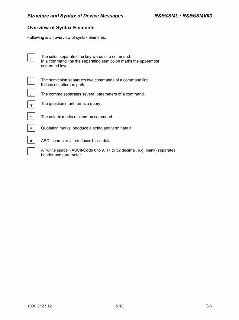
Structure and Syntax of Device Messages R&S®SML / R&S®SMV03
1090.3123.12 E-6 5.12
Overview of Syntax Elements
Following is an overview of syntax elements.
:
;
,
?
*
"
#
The colon separates the key words of a command.In a command line the separating semicolon marks the uppermost command level.
The semicolon separates two commands of a command line. It does not alter the path.
The comma separates several parameters of a command.
The question mark forms a query.
The asterix marks a common command.
Quotation marks introduce a string and terminate it.
ASCI character # introduces block data.
A "white space" (ASCII-Code 0 to 9, 11 to 32 decimal, e.g. blank) separatesheader and parameter.
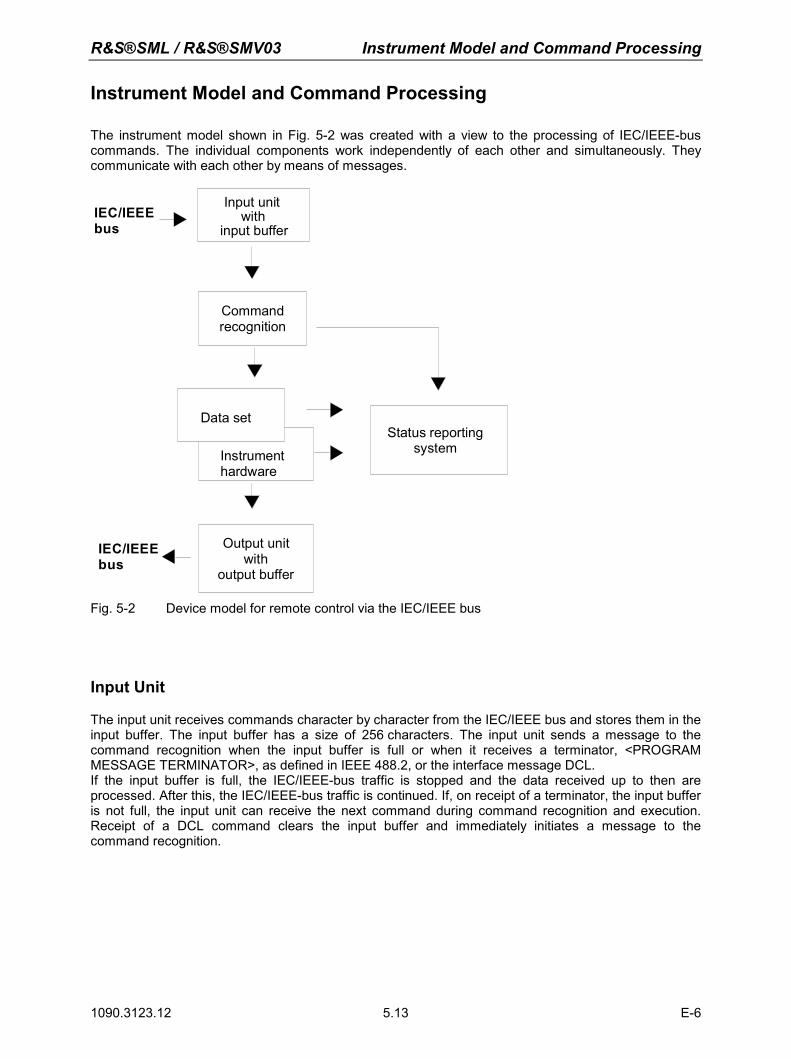
R&S®SML / R&S®SMV03 Instrument Model and Command Processing
1090.3123.12 E-6 5.13
Instrument Model and Command Processing
The instrument model shown in Fig. 5-2 was created with a view to the processing of IEC/IEEE-bus commands. The individual components work independently of each other and simultaneously. They communicate with each other by means of messages.
IEC/IEEEbus
Input unitwith
input buffer
Commandrecognition
Data set
Instrumenthardware
IEC/IEEEbus
Status reporting system
Output unitwith
output buffer
Fig. 5-2 Device model for remote control via the IEC/IEEE bus
Input Unit
The input unit receives commands character by character from the IEC/IEEE bus and stores them in the input buffer. The input buffer has a size of 256 characters. The input unit sends a message to the command recognition when the input buffer is full or when it receives a terminator, <PROGRAM MESSAGE TERMINATOR>, as defined in IEEE 488.2, or the interface message DCL. If the input buffer is full, the IEC/IEEE-bus traffic is stopped and the data received up to then are processed. After this, the IEC/IEEE-bus traffic is continued. If, on receipt of a terminator, the input buffer is not full, the input unit can receive the next command during command recognition and execution. Receipt of a DCL command clears the input buffer and immediately initiates a message to the command recognition.
Instrument Model and Command Processing R&S®SML / R&S®SMV03
1090.3123.12 E-6 5.14
Command Recognition
The command recognition analyzes the data from the input unit in the order the data are received. Only DCL commands are serviced with priority, whereas GET commands (Group Execute Trigger), for example, are processed only after the previously received commands. Each recognized command is immediately transferred to the data set but without being executed there at once. Syntactic errors in commands are detected here and transferred to the status reporting system. The rest of a command line following a syntax error is further analyzed and processed as far as possible. If the command recognition recognizes a terminator or a DCL command, it requests the data set to set the commands now also in the instrument hardware. After this, it is immediately ready to continue processing commands. This means that new commands can be processed while the hardware is being set ("overlapping execution").
Data Set and Instrument Hardware
The term "instrument hardware" is used here to designate the part of the instrument which actually performs the instrument functions: signal generation, measurement, etc. The controller is not included. The data set is a detailed reproduction of the instrument hardware in the software. IEC/IEEE-bus setting commands cause an alteration of the data set. The data set management enters the new values (eg frequency) into the data set but passes them on to the hardware only upon request by the command recognition. As this is only effected at the end of a command line, the sequence of setting commands in the command line is not relevant. The data are only checked for compatibility among one another and with the instrument hardware immediately before they are transferred to the instrument hardware. If it is found that an execution is not possible, an "execution error" is signalled to the status reporting system. All alterations mad to the data set are cancelled, and the instrument hardware is not reset. Due to the delayed checking and hardware setting it is permissible however that impermissible instrument states are briefly set within a command line without an error message being produced. At the end of the command line, however, a permissible instrument state must be attained. Before the data are passed on to the hardware, the settling bit in the STATus:OPERation register is set. The hardware makes the settings and resets the bit when the new state has settled. This procedure can be used for synchronization of command processing. IEC/IEEE-bus queries cause the data set management to send the desired data to the output unit.
Status Reporting System
The status reporting system collects information on the instrument state and makes it available to the output unit upon request. A detailed description of the structure and function is given in section "Status Reporting System".
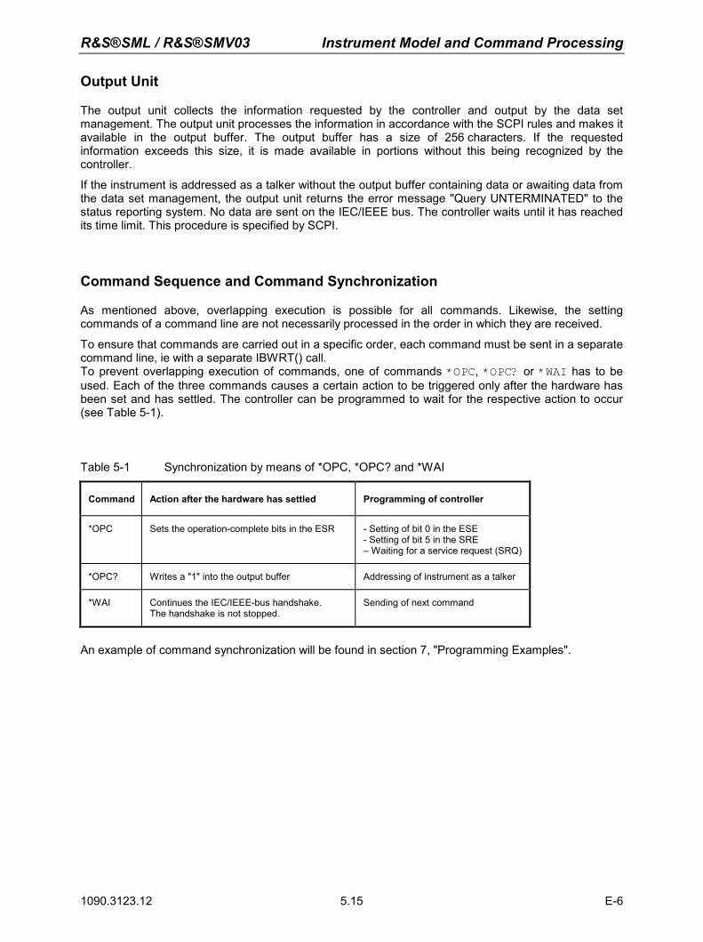
R&S®SML / R&S®SMV03 Instrument Model and Command Processing
1090.3123.12 E-6 5.15
Output Unit
The output unit collects the information requested by the controller and output by the data set management. The output unit processes the information in accordance with the SCPI rules and makes it available in the output buffer. The output buffer has a size of 256 characters. If the requested information exceeds this size, it is made available in portions without this being recognized by the controller.
If the instrument is addressed as a talker without the output buffer containing data or awaiting data from the data set management, the output unit returns the error message "Query UNTERMINATED" to the status reporting system. No data are sent on the IEC/IEEE bus. The controller waits until it has reached its time limit. This procedure is specified by SCPI.
Command Sequence and Command Synchronization
As mentioned above, overlapping execution is possible for all commands. Likewise, the setting commands of a command line are not necessarily processed in the order in which they are received. To ensure that commands are carried out in a specific order, each command must be sent in a separate command line, ie with a separate IBWRT() call. To prevent overlapping execution of commands, one of commands *OPC, *OPC? or *WAI has to be used. Each of the three commands causes a certain action to be triggered only after the hardware has been set and has settled. The controller can be programmed to wait for the respective action to occur (see Table 5-1).
Table 5-1 Synchronization by means of *OPC, *OPC? and *WAI
Command Action after the hardware has settled Programming of controller
*OPC Sets the operation-complete bits in the ESR - Setting of bit 0 in the ESE - Setting of bit 5 in the SRE – Waiting for a service request (SRQ)
*OPC? Writes a "1" into the output buffer Addressing of instrument as a talker
*WAI Continues the IEC/IEEE-bus handshake. The handshake is not stopped.
Sending of next command
An example of command synchronization will be found in section 7, "Programming Examples".
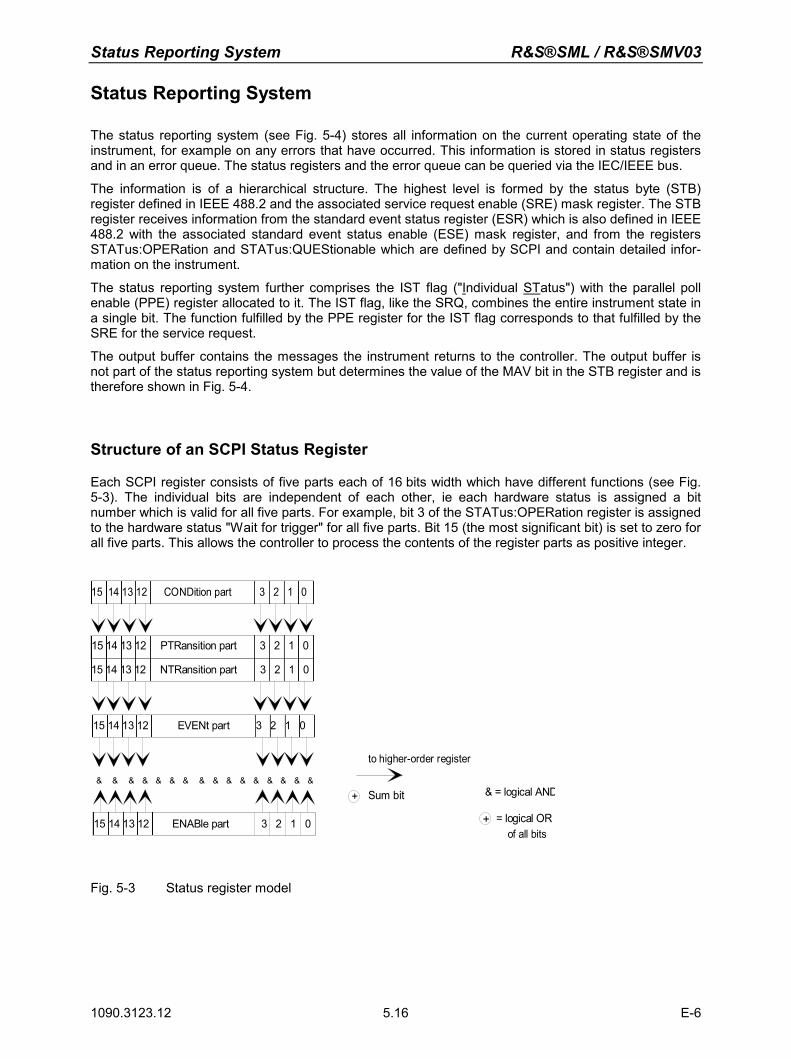
Status Reporting System R&S®SML / R&S®SMV03
1090.3123.12 E-6 5.16
Status Reporting System
The status reporting system (see Fig. 5-4) stores all information on the current operating state of the instrument, for example on any errors that have occurred. This information is stored in status registers and in an error queue. The status registers and the error queue can be queried via the IEC/IEEE bus. The information is of a hierarchical structure. The highest level is formed by the status byte (STB) register defined in IEEE 488.2 and the associated service request enable (SRE) mask register. The STB register receives information from the standard event status register (ESR) which is also defined in IEEE 488.2 with the associated standard event status enable (ESE) mask register, and from the registers STATus:OPERation and STATus:QUEStionable which are defined by SCPI and contain detailed infor-mation on the instrument. The status reporting system further comprises the IST flag ("Individual STatus") with the parallel poll enable (PPE) register allocated to it. The IST flag, like the SRQ, combines the entire instrument state in a single bit. The function fulfilled by the PPE register for the IST flag corresponds to that fulfilled by the SRE for the service request. The output buffer contains the messages the instrument returns to the controller. The output buffer is not part of the status reporting system but determines the value of the MAV bit in the STB register and is therefore shown in Fig. 5-4.
Structure of an SCPI Status Register
Each SCPI register consists of five parts each of 16 bits width which have different functions (see Fig. 5-3). The individual bits are independent of each other, ie each hardware status is assigned a bit number which is valid for all five parts. For example, bit 3 of the STATus:OPERation register is assigned to the hardware status "Wait for trigger" for all five parts. Bit 15 (the most significant bit) is set to zero for all five parts. This allows the controller to process the contents of the register parts as positive integer.
15 14 13 12 PTRansition part 3 2 1 0
15 14 13 12 EVENt part 3 2 1 0
15 14 13 12 ENABle part 3 2 1 0
& & & & & & & & & & & & & & & &
to higher-order register
Sum bit & = logical AND
= logical ORof all bits
+
+
15 14 13 12 NTRansition part 3 2 1 0
15 14 13 12 CONDition part 3 2 1 0
Fig. 5-3 Status register model
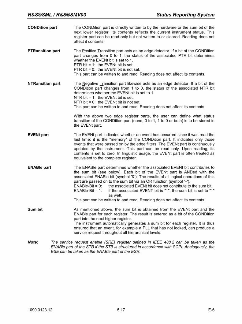
R&S®SML / R&S®SMV03 Status Reporting System
1090.3123.12 E-6 5.17
CONDition part The CONDition part is directly written to by the hardware or the sum bit of the next lower register. Its contents reflects the current instrument status. This register part can be read only but not written to or cleared. Reading does not affect it contents.
PTRansition part The Positive Transition part acts as an edge detector. If a bit of the CONDition part changes from 0 to 1, the status of the associated PTR bit determines whether the EVENt bit is set to 1.
PTR bit = 1: the EVENt bit is set. PTR bit = 0: the EVENt bit is not set. This part can be written to and read. Reading does not affect its contents.
NTRansition part The Negative Transition part likewise acts as an edge detector. If a bit of the CONDition part changes from 1 to 0, the status of the associated NTR bit determines whether the EVENt bit is set to 1.
NTR bit = 1: the EVENt bit is set. NTR bit = 0: the EVENt bit is not set. This part can be written to and read. Reading does not affect its contents.
With the above two edge register parts, the user can define what status transition of the CONDition part (none, 0 to 1, 1 to 0 or both) is to be stored in the EVENt part.
EVENt part The EVENt part indicates whether an event has occurred since it was read the
last time; it is the "memory" of the CONDition part. It indicates only those events that were passed on by the edge filters. The EVENt part is continuously updated by the instrument. This part can be read only. Upon reading, its contents is set to zero. In linguistic usage, the EVENt part is often treated as equivalent to the complete register.
ENABle part The ENABle part determines whether the associated EVENt bit contributes to the sum bit (see below). Each bit of the EVENt part is ANDed with the associated ENABle bit (symbol '&'). The results of all logical operations of this part are passed on to the sum bit via an OR function (symbol '+').
ENABle-Bit = 0: the associated EVENt bit does not contribute to the sum bit. ENABle-Bit = 1: if the associated EVENT bit is "1", the sum bit is set to "1"
as well. This part can be written to and read. Reading does not affect its contents. Sum bit As mentioned above, the sum bit is obtained from the EVENt part and the
ENABle part for each register. The result is entered as a bit of the CONDition part into the next higher register. The instrument automatically generates a sum bit for each register. It is thus ensured that an event, for example a PLL that has not locked, can produce a service request throughout all hierarchical levels.
Note: The service request enable (SRE) register defined in IEEE 488.2 can be taken as the ENABle part of the STB if the STB is structured in accordance with SCPI. Analogously, the ESE can be taken as the ENABle part of the ESR.
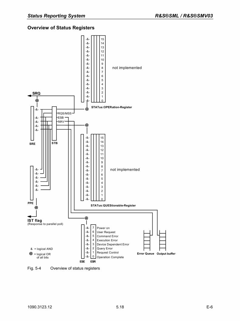
Status Reporting System R&S®SML / R&S®SMV03
1090.3123.12 E-6 5.18
Overview of Status Registers
SRE STB
STATus:OPERation-Register
PPE
IST flag(Response to parallel poll)
& = logical AND
= logical OR of all bits
ESE ESR
Error Queue Output buffer
SRQ
RQS/MSSESBMAV
Power onUser RequestCommand ErrorExecution ErrorDevice Dependent ErrorQuery ErrorRequest ControlOperation Complete
1514131211109876543210
-&--&--&--&--&--&--&--&--&--&--&--&--&--&--&--&-
1514131211109876543210
-&--&--&--&--&--&--&--&--&--&--&--&--&--&--&--&-
-&--&--&--&--&--&-
-&-
-&--&--&--&-
-&--&--&--&--&--&--&--&-
76543210
STATus:QUEStionable-Register
not implemented
not implemented
Fig. 5-4 Overview of status registers
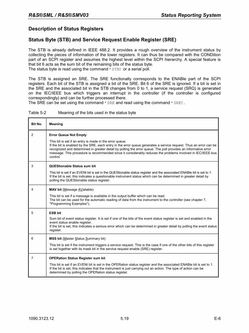
R&S®SML / R&S®SMV03 Status Reporting System
1090.3123.12 E-6 5.19
Description of Status Registers
Status Byte (STB) and Service Request Enable Register (SRE)
The STB is already defined in IEEE 488.2. It provides a rough overview of the instrument status by collecting the pieces of information of the lower registers. It can thus be compared with the CONDition part of an SCPI register and assumes the highest level within the SCPI hierarchy. A special feature is that bit 6 acts as the sum bit of the remaining bits of the status byte. The status byte is read using the command *STB? or a serial poll. The STB is assigned an SRE. The SRE functionally corresponds to the ENABle part of the SCPI registers. Each bit of the STB is assigned a bit of the SRE. Bit 6 of the SRE is ignored. If a bit is set in the SRE and the associated bit in the STB changes from 0 to 1, a service request (SRQ) is generated on the IEC/IEEE bus which triggers an interrupt in the controller (if the controller is configured correspondingly) and can be further processed there. The SRE can be set using the command *SRE and read using the command *SRE?.
Table 5-2 Meaning of the bits used in the status byte
Bit No. Meaning
2 Error Queue Not Empty
This bit is set if an entry is made in the error queue. If the bit is enabled by the SRE, each entry in the error queue generates a service request. Thus an error can be recognized and determined in greater detail by polling the error queue. The poll provides an informative error message. This procedure is recommended since it considerably reduces the problems involved in IEC/IEEE-bus control.
3 QUEStionable Status sum bit
This bit is set if an EVENt bit is set in the QUEStionable status register and the associated ENABle bit is set to 1. If the bit is set, this indicates a questionable instrument status which can be determined in greater detail by polling the QUEStionable status register.
4 MAV bit (Message AVailable)
This bit is set if a message is available in the output buffer which can be read. The bit can be used for the automatic reading of data from the instrument to the controller (see chapter 7, "Programming Examples").
5 ESB bit Sum bit of event status register. It is set if one of the bits of the event status register is set and enabled in the event status enable register. If the bit is set, this indicates a serious error which can be determined in greater detail by polling the event status register.
6 MSS bit (Master Status Summary bit)
This bit is set if the instrument triggers a service request. This is the case if one of the other bits of this register is set together with its mask bit in the service request enable (SRE) register.
7 OPERation Status Register sum bit
This bit is set if an EVENt bit is set in the OPERation status register and the associated ENABle bit is set to 1. If the bit is set, this indicates that the instrument is just carrying out an action. The type of action can be determined by polling the OPERation status register.
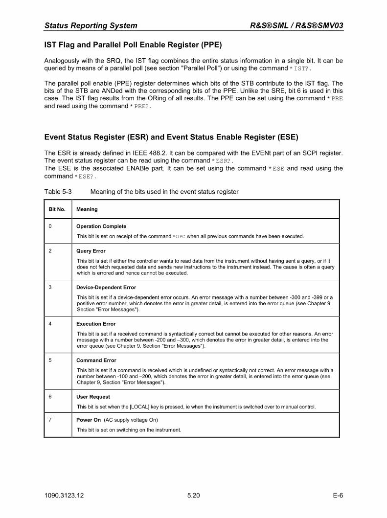
Status Reporting System R&S®SML / R&S®SMV03
1090.3123.12 E-6 5.20
IST Flag and Parallel Poll Enable Register (PPE)
Analogously with the SRQ, the IST flag combines the entire status information in a single bit. It can be queried by means of a parallel poll (see section "Parallel Poll") or using the command *IST?.
The parallel poll enable (PPE) register determines which bits of the STB contribute to the IST flag. The bits of the STB are ANDed with the corresponding bits of the PPE. Unlike the SRE, bit 6 is used in this case. The IST flag results from the ORing of all results. The PPE can be set using the command *PRE and read using the command *PRE?.
Event Status Register (ESR) and Event Status Enable Register (ESE)
The ESR is already defined in IEEE 488.2. It can be compared with the EVENt part of an SCPI register. The event status register can be read using the command *ESR?.The ESE is the associated ENABle part. It can be set using the command *ESE and read using the command *ESE?.
Table 5-3 Meaning of the bits used in the event status register
Bit No. Meaning
0 Operation Complete
This bit is set on receipt of the command *OPC when all previous commands have been executed. 2 Query Error
This bit is set if either the controller wants to read data from the instrument without having sent a query, or if it does not fetch requested data and sends new instructions to the instrument instead. The cause is often a query which is errored and hence cannot be executed.
3 Device-Dependent Error
This bit is set if a device-dependent error occurs. An error message with a number between -300 and -399 or a positive error number, which denotes the error in greater detail, is entered into the error queue (see Chapter 9, Section "Error Messages").
4 Execution Error
This bit is set if a received command is syntactically correct but cannot be executed for other reasons. An error message with a number between -200 and –300, which denotes the error in greater detail, is entered into the error queue (see Chapter 9, Section "Error Messages").
5 Command Error
This bit is set if a command is received which is undefined or syntactically not correct. An error message with a number between -100 and –200, which denotes the error in greater detail, is entered into the error queue (see Chapter 9, Section "Error Messages").
6 User Request
This bit is set when the [LOCAL] key is pressed, ie when the instrument is switched over to manual control.
7 Power On (AC supply voltage On)
This bit is set on switching on the instrument.
R&S®SML / R&S®SMV03 Status Reporting System
1090.3123.12 E-6 5.21
STATus:OPERation Register
Not impemented
STATus:QUEStionable Register
Not implemented
Status Reporting System R&S®SML / R&S®SMV03
1090.3123.12 E-6 5.22
Use of Status Reporting System
To make effective use of the status reporting system, the information collected there must be transferred to the controller and further processed. There are several methods to this effect which are described in the following. For detailed examples see chapter 7, "Programming Examples").
Service Request, Making Use of Hierarchy Structure
Under certain conditions, the instrument can send a service request (SRQ) to the controller. The service request normally triggers an interrupt at the controller to which the control program can respond with corresponding actions. Fig. 5-4 shows that an SRQ is triggered if one or several of the bits 2, 3, 4, 5 and 7 of the status byte are set and enabled in the SRE. Each of these bits combines the information of another register, the error queue or the output buffer. By setting the ENABle parts of the status registers accordingly, it is achieved that arbitrary bits of an arbitrary status register trigger an SRQ. To make use of the possibilities of the service request, all bits of the SRE and ESE enable registers should be set to "1". Examples (see also Fig. 5-4 and chapter 7, "Programming Examples"): Use of command *OPC to generate an SRQ Set bit 0 in the ESE (Operation Complete). Set bit 5 in the SRE (ESB). The instrument generates an SRQ after completion of its settings. Indication of end of sweep by means of an SRQ at the controller Set bit 7 (sum bit of STATus:OPERation register) in SRE. Set bit 3 (sweeping) in STATus:OPERation:ENABle. Set bit 3 in STATus:OPERation:NTRansition so that the transition of sweeping bit 3 from 1 to 0
(end of sweep) is recorded in the EVENt part. The instrument generates an SRQ after completion of a sweep. The SRQ is the only way for the instrument to become active on its own. Each controller program should, therefore, set the instrument such that a service request is triggered in the event of a malfunction. The program should react appropriately to the service request. A detailed example of a service request routine is included in chapter 7, "Programming Examples".
Serial Poll
In a serial poll, just as with command *STB, the status byte of an instrument is queried. However, the query is implemented by means of interface messages and is therefore clearly faster. The serial-poll method has already been defined in IEEE 488.1 and used to be the only standard method for different instruments to query the status byte. The method also works with instruments which do not adhere to SCPI nor to IEEE 488.2. The QuickBASIC command for executing a serial poll is IBRSP(). Serial polling is mainly used to obtain a fast overview of the states of several instruments connected to the IEC/IEEE bus.
R&S®SML / R&S®SMV03 Status Reporting System
1090.3123.12 E-6 5.23
Parallel Poll
In a parallel poll, up to eight instruments are simultaneously requested by the controller by means of a single command to transmit 1 bit of information each on the data lines, ie to set the data line allocated to each instrument to logically "0" or "1". Analogously to the SRE register, which determines under what conditions an SRQ is generated, there is a parallel poll enable (PPE) register, which is likewise ANDed with the STB bit by bit, with bit 6 being taken into account. The results are ORed, and the result of this is sent (possibly inverted) in response to a parallel poll by the controller. The result can also be queried without a parallel poll using the command *IST.
The instrument first has to be set for parallel polling by means of the QuickBASIC command IBPPC().This command allocates a data line to the instrument and determines whether the response is to be inverted. The parallel poll itself is executed using IBRPP().
The parallel-poll method is mainly used in order to find out quickly, after an SRQ, which instrument has sent the service request if there are many instruments connected to the IEC/IEEE bus. To this effect, the SRE and the PPE must be set to the same value. A detailed example on parallel polling will be found in chapter 7, "Programming Examples".
Query by Means of Commands
Each part of every status register can be read by means of a query. The queries to be used are included with the detailed description of the registers. In response to a query, a number is always returned which represents the bit pattern of the register queried. The number is evaluated by the controller program. Queries are normally used after an SRQ to obtain more detailed information on the cause of the SRQ.
Error Queue Query
Each error state in the instrument leads to an entry in the error queue. The entries to the error queue are detailed plain-text error messages which can be displayed in the Error menu by manual control or queried via the IEC/IEEE bus with the command SYSTem:ERRor?. Each call of SYSTem:ERRor? provides one entry from the error queue. If no more error messages are stored there, the instrument responds with 0, ie "No error". The error queue should be queried by the controller program after each SRQ as the entries provide a more precise description of the cause of an error than the status registers. Especially during the test phase of a controller program the error queue should be queried regularly since errored commands from the controller to the instrument are also recorded in the error queue.
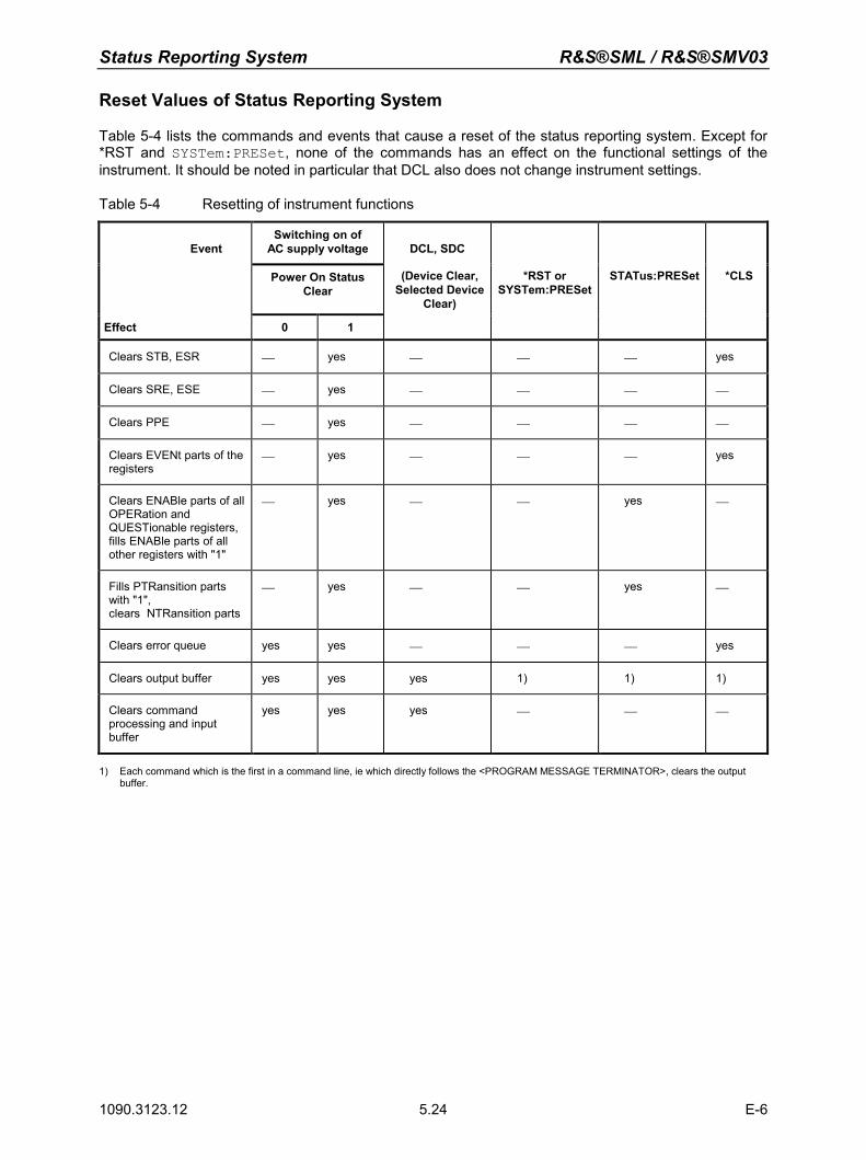
Status Reporting System R&S®SML / R&S®SMV03
1090.3123.12 E-6 5.24
Reset Values of Status Reporting System
Table 5-4 lists the commands and events that cause a reset of the status reporting system. Except for *RST and SYSTem:PRESet, none of the commands has an effect on the functional settings of the instrument. It should be noted in particular that DCL also does not change instrument settings.
Table 5-4 Resetting of instrument functions
Event
Switching on of AC supply voltage
DCL, SDC
Power On Status Clear
(Device Clear,Selected Device
Clear)
*RST or SYSTem:PRESet
STATus:PRESet *CLS
Effect 0 1
Clears STB, ESR yes yes
Clears SRE, ESE yes
Clears PPE yes
Clears EVENt parts of the registers
yes yes
Clears ENABle parts of all OPERation and QUESTionable registers,fills ENABle parts of all other registers with "1"
yes yes
Fills PTRansition parts with "1", clears NTRansition parts
yes yes
Clears error queue yes yes yes
Clears output buffer yes yes yes 1) 1) 1)
Clears command processing and input buffer
yes yes yes
1) Each command which is the first in a command line, ie which directly follows the <PROGRAM MESSAGE TERMINATOR>, clears the output buffer.
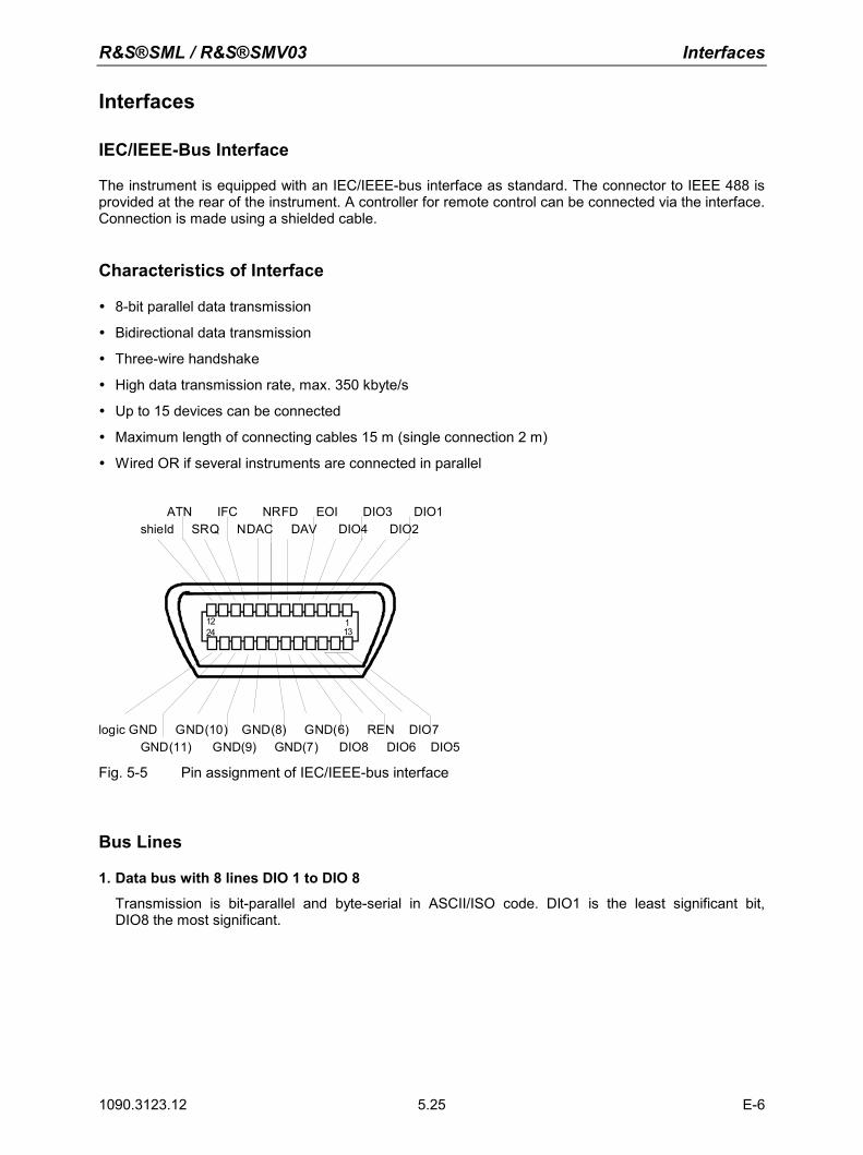
R&S®SML / R&S®SMV03 Interfaces
1090.3123.12 E-6 5.25
Interfaces
IEC/IEEE-Bus Interface
The instrument is equipped with an IEC/IEEE-bus interface as standard. The connector to IEEE 488 is provided at the rear of the instrument. A controller for remote control can be connected via the interface. Connection is made using a shielded cable.
Characteristics of Interface
8-bit parallel data transmission
Bidirectional data transmission
Three-wire handshake
High data transmission rate, max. 350 kbyte/s
Up to 15 devices can be connected
Maximum length of connecting cables 15 m (single connection 2 m)
Wired OR if several instruments are connected in parallel
12 11324
shield SRQ NDAC DAV DIO4 DIO2
logic GND GND(10) GND(8) GND(6) REN DIO7 GND(11) GND(9) GND(7) DIO8 DIO6 DIO5
ATN IFC NRFD EOI DIO3 DIO1
Fig. 5-5 Pin assignment of IEC/IEEE-bus interface
Bus Lines
1. Data bus with 8 lines DIO 1 to DIO 8
Transmission is bit-parallel and byte-serial in ASCII/ISO code. DIO1 is the least significant bit, DIO8 the most significant.
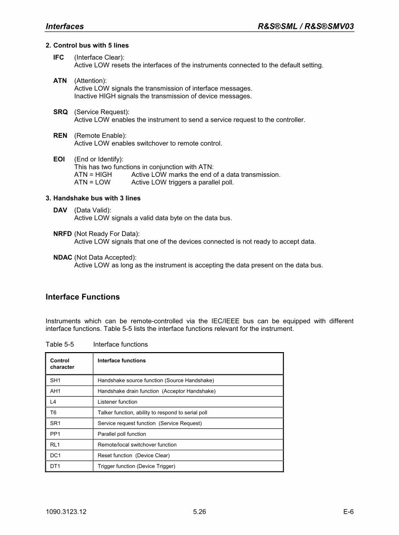
Interfaces R&S®SML / R&S®SMV03
1090.3123.12 E-6 5.26
2. Control bus with 5 lines
IFC (Interface Clear): Active LOW resets the interfaces of the instruments connected to the default setting.
ATN (Attention):
Active LOW signals the transmission of interface messages. Inactive HIGH signals the transmission of device messages.
SRQ (Service Request): Active LOW enables the instrument to send a service request to the controller.
REN (Remote Enable): Active LOW enables switchover to remote control.
EOI (End or Identify): This has two functions in conjunction with ATN: ATN = HIGH Active LOW marks the end of a data transmission. ATN = LOW Active LOW triggers a parallel poll.
3. Handshake bus with 3 lines
DAV (Data Valid): Active LOW signals a valid data byte on the data bus.
NRFD (Not Ready For Data): Active LOW signals that one of the devices connected is not ready to accept data.
NDAC (Not Data Accepted): Active LOW as long as the instrument is accepting the data present on the data bus.
Interface Functions
Instruments which can be remote-controlled via the IEC/IEEE bus can be equipped with different interface functions. Table 5-5 lists the interface functions relevant for the instrument.
Table 5-5 Interface functions
Control character
Interface functions
SH1 Handshake source function (Source Handshake)
AH1 Handshake drain function (Acceptor Handshake)
L4 Listener function
T6 Talker function, ability to respond to serial poll
SR1 Service request function (Service Request)
PP1 Parallel poll function
RL1 Remote/local switchover function
DC1 Reset function (Device Clear)
DT1 Trigger function (Device Trigger)
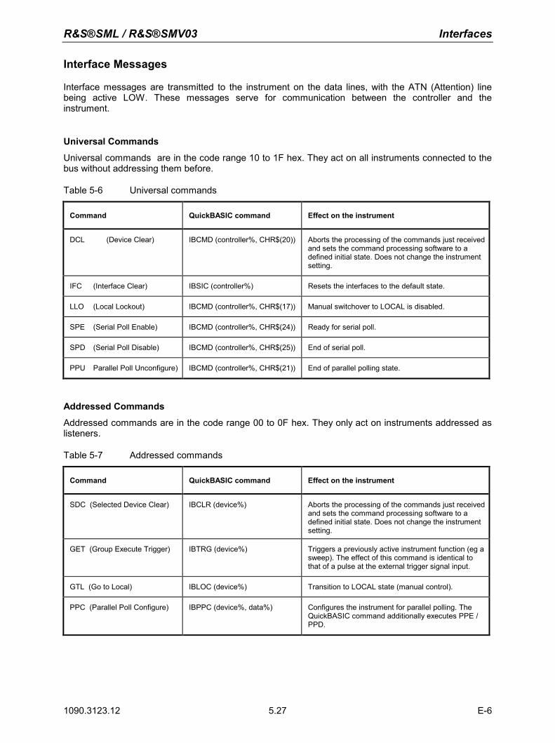
R&S®SML / R&S®SMV03 Interfaces
1090.3123.12 E-6 5.27
Interface Messages
Interface messages are transmitted to the instrument on the data lines, with the ATN (Attention) line being active LOW. These messages serve for communication between the controller and the instrument.
Universal Commands Universal commands are in the code range 10 to 1F hex. They act on all instruments connected to the bus without addressing them before.
Table 5-6 Universal commands
Command QuickBASIC command Effect on the instrument
DCL (Device Clear) IBCMD (controller%, CHR$(20)) Aborts the processing of the commands just received and sets the command processing software to a defined initial state. Does not change the instrument setting.
IFC (Interface Clear) IBSIC (controller%) Resets the interfaces to the default state.
LLO (Local Lockout) IBCMD (controller%, CHR$(17)) Manual switchover to LOCAL is disabled.
SPE (Serial Poll Enable) IBCMD (controller%, CHR$(24)) Ready for serial poll.
SPD (Serial Poll Disable) IBCMD (controller%, CHR$(25)) End of serial poll.
PPU Parallel Poll Unconfigure) IBCMD (controller%, CHR$(21)) End of parallel polling state.
Addressed Commands Addressed commands are in the code range 00 to 0F hex. They only act on instruments addressed as listeners.
Table 5-7 Addressed commands
Command QuickBASIC command Effect on the instrument
SDC (Selected Device Clear) IBCLR (device%) Aborts the processing of the commands just received and sets the command processing software to a defined initial state. Does not change the instrument setting.
GET (Group Execute Trigger) IBTRG (device%) Triggers a previously active instrument function (eg a sweep). The effect of this command is identical to that of a pulse at the external trigger signal input.
GTL (Go to Local) IBLOC (device%) Transition to LOCAL state (manual control).
PPC (Parallel Poll Configure) IBPPC (device%, data%) Configures the instrument for parallel polling. The QuickBASIC command additionally executes PPE / PPD.
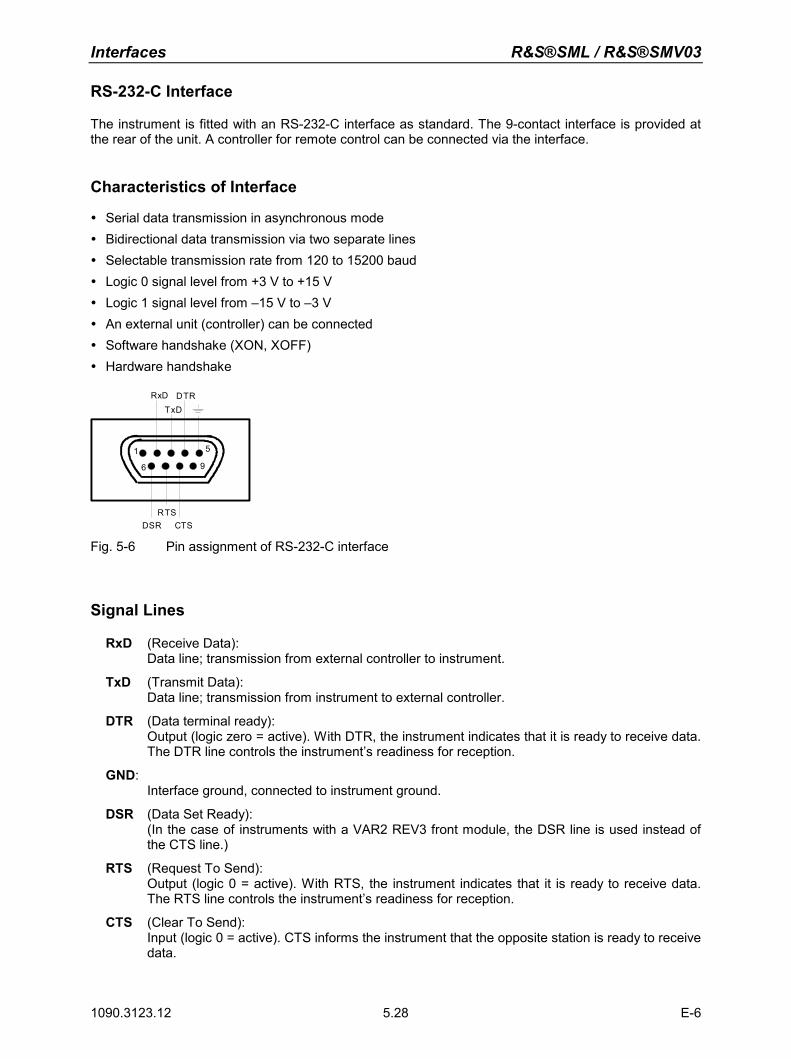
Interfaces R&S®SML / R&S®SMV03
1090.3123.12 E-6 5.28
RS-232-C Interface
The instrument is fitted with an RS-232-C interface as standard. The 9-contact interface is provided at the rear of the unit. A controller for remote control can be connected via the interface.
Characteristics of Interface
Serial data transmission in asynchronous mode Bidirectional data transmission via two separate lines Selectable transmission rate from 120 to 15200 baud Logic 0 signal level from +3 V to +15 V Logic 1 signal level from –15 V to –3 V An external unit (controller) can be connected Software handshake (XON, XOFF) Hardware handshake
RxD DTR
1
6
5
9
TxD
DSR CTSRTS
Fig. 5-6 Pin assignment of RS-232-C interface
Signal Lines
RxD (Receive Data): Data line; transmission from external controller to instrument.
TxD (Transmit Data):
Data line; transmission from instrument to external controller.
DTR (Data terminal ready): Output (logic zero = active). With DTR, the instrument indicates that it is ready to receive data. The DTR line controls the instrument’s readiness for reception.
GND:
Interface ground, connected to instrument ground.
DSR (Data Set Ready): (In the case of instruments with a VAR2 REV3 front module, the DSR line is used instead of the CTS line.)
RTS (Request To Send):
Output (logic 0 = active). With RTS, the instrument indicates that it is ready to receive data. The RTS line controls the instrument’s readiness for reception.
CTS (Clear To Send):
Input (logic 0 = active). CTS informs the instrument that the opposite station is ready to receive data.
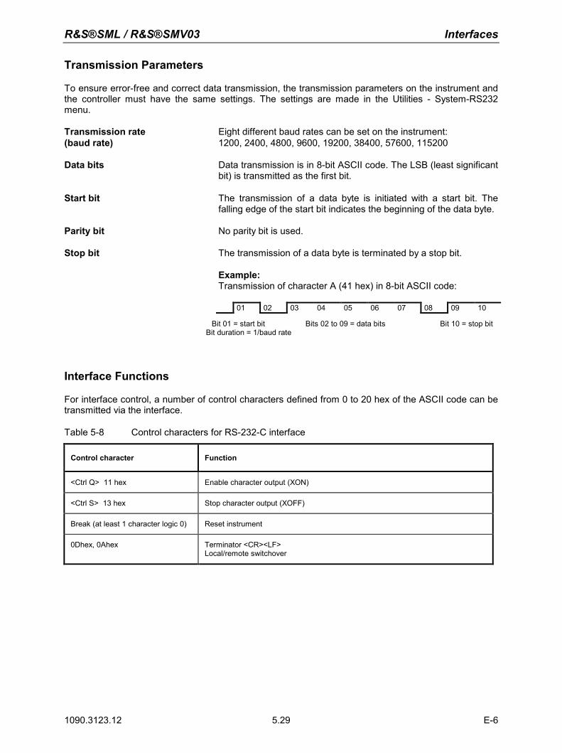
R&S®SML / R&S®SMV03 Interfaces
1090.3123.12 E-6 5.29
Transmission Parameters
To ensure error-free and correct data transmission, the transmission parameters on the instrument and the controller must have the same settings. The settings are made in the Utilities - System-RS232 menu. Transmission rate Eight different baud rates can be set on the instrument: (baud rate) 1200, 2400, 4800, 9600, 19200, 38400, 57600, 115200 Data bits Data transmission is in 8-bit ASCII code. The LSB (least significant
bit) is transmitted as the first bit. Start bit The transmission of a data byte is initiated with a start bit. The
falling edge of the start bit indicates the beginning of the data byte. Parity bit No parity bit is used. Stop bit The transmission of a data byte is terminated by a stop bit.
Example: Transmission of character A (41 hex) in 8-bit ASCII code:
01 02 03 04 05 06 07 08 09 10
Bit 01 = start bit Bits 02 to 09 = data bits Bit 10 = stop bit Bit duration = 1/baud rate
Interface Functions
For interface control, a number of control characters defined from 0 to 20 hex of the ASCII code can be transmitted via the interface.
Table 5-8 Control characters for RS-232-C interface
Control character Function
<Ctrl Q> 11 hex Enable character output (XON)
<Ctrl S> 13 hex Stop character output (XOFF)
Break (at least 1 character logic 0) Reset instrument
0Dhex, 0Ahex Terminator <CR><LF> Local/remote switchover
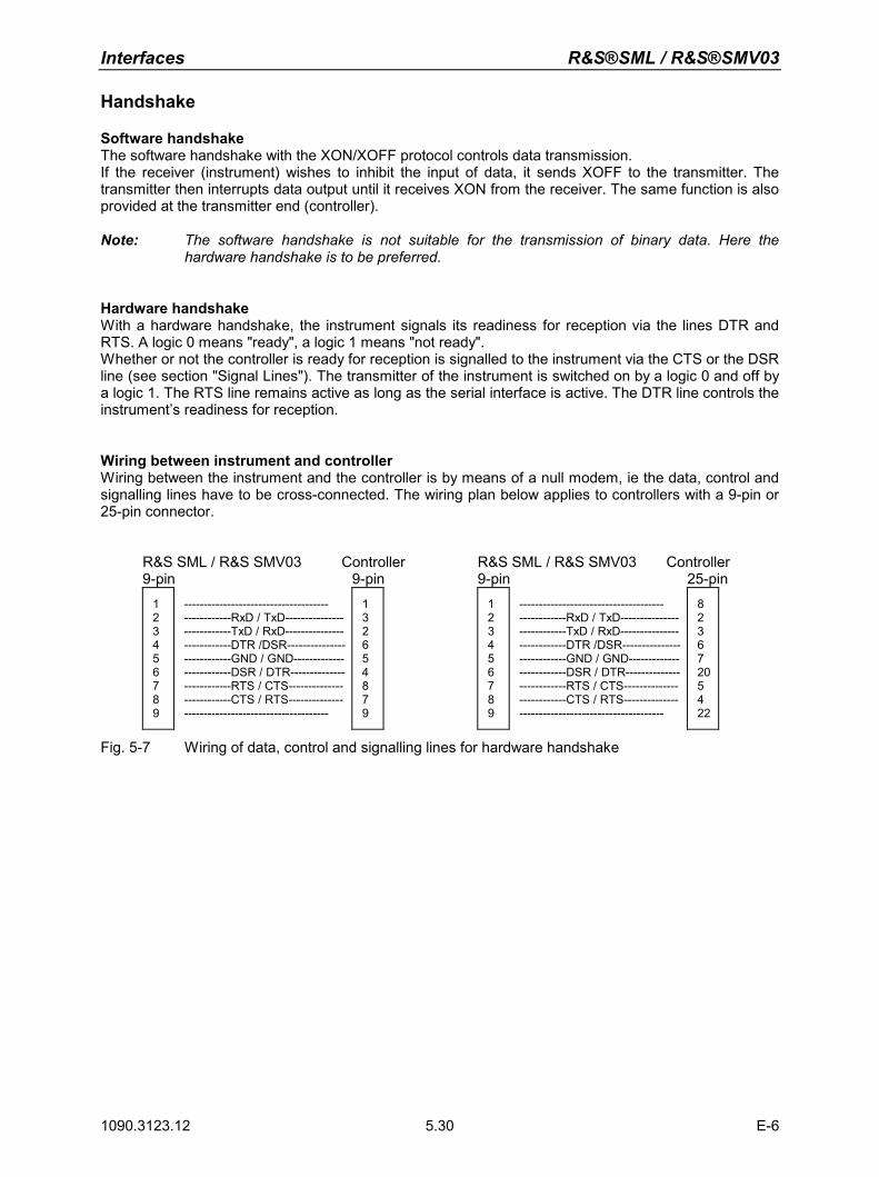
Interfaces R&S®SML / R&S®SMV03
1090.3123.12 E-6 5.30
Handshake
Software handshake The software handshake with the XON/XOFF protocol controls data transmission. If the receiver (instrument) wishes to inhibit the input of data, it sends XOFF to the transmitter. The transmitter then interrupts data output until it receives XON from the receiver. The same function is also provided at the transmitter end (controller). Note: The software handshake is not suitable for the transmission of binary data. Here the
hardware handshake is to be preferred.
Hardware handshake With a hardware handshake, the instrument signals its readiness for reception via the lines DTR and RTS. A logic 0 means "ready", a logic 1 means "not ready". Whether or not the controller is ready for reception is signalled to the instrument via the CTS or the DSR line (see section "Signal Lines"). The transmitter of the instrument is switched on by a logic 0 and off by a logic 1. The RTS line remains active as long as the serial interface is active. The DTR line controls the instrument’s readiness for reception.
Wiring between instrument and controller Wiring between the instrument and the controller is by means of a null modem, ie the data, control and signalling lines have to be cross-connected. The wiring plan below applies to controllers with a 9-pin or 25-pin connector.
R&S SML / R&S SMV03 Controller R&S SML / R&S SMV03 Controller 9-pin 9-pin 9-pin 25-pin 1
23456789
------------------------------------- ------------RxD / TxD---------------------------TxD / RxD---------------------------DTR /DSR---------------------------GND / GND-------------------------DSR / DTR--------------------------RTS / CTS--------------------------CTS / RTS---------------------------------------------------
132654879
123456789
------------------------------------- ------------RxD / TxD---------------------------TxD / RxD---------------------------DTR /DSR---------------------------GND / GND-------------------------DSR / DTR--------------------------RTS / CTS--------------------------CTS / RTS---------------------------------------------------
82367205422
Fig. 5-7 Wiring of data, control and signalling lines for hardware handshake
R&S®SML / R&S®SMV03 Description of Commands
1090.3123.12 E-6 6.1
6 Remote Control – Description of Commands
In the following sections, all commands implemented in the instrument are first listed in tables and then described in detail, separated according to the command system. The notation corresponds to the one of the SCPI standards to a large extent. The SCPI conformity information can be taken from the list of commands at the end of this chapter. The description of manual operation, Chapter 4, indicates the corresponding IEC/IEEE-bus command for each manual setting. A general introduction to remote control and a description of the status registers are to be found in Chapter 5. Detailed program examples of the main functions are to be found in Chapter 7.
Note: In contrast to manual control, which is intended for maximum possible operating convenience, the priority of remote control is the predictability of the device status. This means that when incompatible settings are attempted, the command is ignored and the device status remains unchanged, i.e. is not adapted to other settings. Therefore, IEC/IEEE-bus control programs should always define an initial device status (e.g. with command *RST) and then implement the required settings. This manual contains the commands (syntax) of the firmware version 2.51.
Notation
Table of Commands Command: In the command column, the table provides an overview of the commands
and their hierarchical arrangement (see indentations).
Parameter: In the parameter column the requested parameters are indicated together with their specified range.
Unit: The unit column indicates the basic unit of the physical parameters.
Remark: In the remark column an indication is made on
– whether the command does not have a query form, – whether the command has only one query form, – whether this command is implemented only with a certain option of the
instrument.
Indentations The different levels of the SCPI command hierarchy are represented in the table by means of indentations to the right. The lower the level is, the farther the indentation to the right is. Please observe that the complete notation of the command always includes the higher levels as well.
Example: :SOURce:FM:MODE is represented in the table as follows:
:SOURce first level
:FM second level :MODE third level In the individual description, the complete notation of the command is given. An example for each command and - if it exists - the default value (*RST) is written out at the end of the individual description.
Description of Commands R&S®SML / R&S®SMV03
1090.3123.12 E-6 6.2
Upper/lower case Upper/lower case letters serve to mark the long or short form of the key notation words of a command in the description. The instrument itself does not
distinguish between upper and lower case letters. Special characters | A selection of key words with an identical effect exists for several
commands. These key words are indicated in the same line, they are separated by a vertical stroke. Only one of these key words has to be indicated in the header of the command. The effect of the command is independent of which of the key words is indicated.
Example: :SOURce
:FREQuency:CW|:FIXed
The two following commands of identical meaning can be formed. They set the frequency of the constantly frequent signal to 9 kHz:
:SOURce:FREQuency:CW 9E3 = SOURce:FREQuency:FIXed 9E3
A vertical stroke in indicating the parameters marks alternative possibilities in the sense of "or". The effect of the command is different, depending on which parameter is entered.
Example: Selection of the parameters for the command
SOURce:COUPling AC | DC
If parameter AC is selected, only the AC content is fed through, in the case of DC, the DC as well as the AC content.
[ ] Key words in square brackets can be omitted when composing the header
(cf. Chapter 5, Section "Optional Keywords"). The full command length must be accepted by the instrument for reasons of compatibility with the SCPI standards.
Parameters in square brackets can optionally be incorporated in the command or omitted as well.
Parameters in braces can optionally be incorporated in the command either
not at all, once or several times.
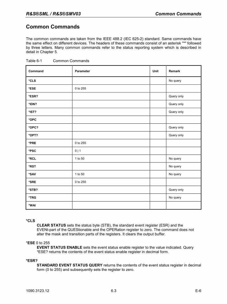
R&S®SML / R&S®SMV03 Common Commands
1090.3123.12 6.3 E-6
Common Commands
The common commands are taken from the IEEE 488.2 (IEC 625-2) standard. Same commands have the same effect on different devices. The headers of these commands consist of an asterisk "*" followed by three letters. Many common commands refer to the status reporting system which is described in detail in Chapter 5.
Table 6-1 Common Commands
Command Parameter Unit Remark
*CLS No query
*ESE 0 to 255
*ESR? Query only
*IDN? Query only
*IST? Query only
*OPC
*OPC? Query only
*OPT? Query only
*PRE 0 to 255
*PSC 0 | 1
*RCL 1 to 50 No query
*RST No query
*SAV 1 to 50 No query
*SRE 0 to 255
*STB? Query only
*TRG No query
*WAI
*CLS CLEAR STATUS sets the status byte (STB), the standard event register (ESR) and the EVENt-part of the QUEStionable and the OPERation register to zero. The command does not alter the mask and transition parts of the registers. It clears the output buffer.
*ESE 0 to 255
EVENT STATUS ENABLE sets the event status enable register to the value indicated. Query *ESE? returns the contents of the event status enable register in decimal form.
*ESR? STANDARD EVENT STATUS QUERY returns the contents of the event status register in decimal form (0 to 255) and subsequently sets the register to zero.
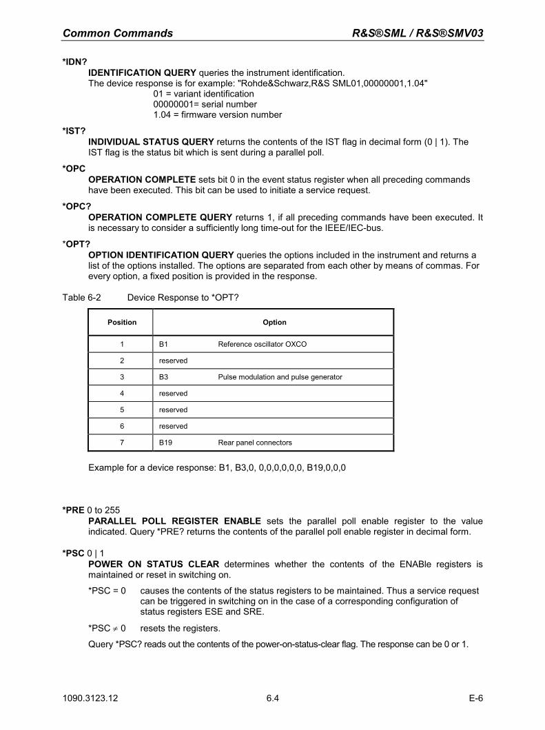
Common Commands R&S®SML / R&S®SMV03
1090.3123.12 6.4 E-6
*IDN? IDENTIFICATION QUERY queries the instrument identification. The device response is for example: "Rohde&Schwarz,R&S SML01,00000001,1.04"
01 = variant identification 00000001= serial number 1.04 = firmware version number
*IST?
INDIVIDUAL STATUS QUERY returns the contents of the IST flag in decimal form (0 | 1). The IST flag is the status bit which is sent during a parallel poll.
*OPC
OPERATION COMPLETE sets bit 0 in the event status register when all preceding commands have been executed. This bit can be used to initiate a service request.
*OPC?
OPERATION COMPLETE QUERY returns 1, if all preceding commands have been executed. It is necessary to consider a sufficiently long time-out for the IEEE/IEC-bus.
*OPT?
OPTION IDENTIFICATION QUERY queries the options included in the instrument and returns a list of the options installed. The options are separated from each other by means of commas. For every option, a fixed position is provided in the response.
Table 6-2 Device Response to *OPT?
Position Option
1 B1 Reference oscillator OXCO
2 reserved
3 B3 Pulse modulation and pulse generator
4 reserved
5 reserved
6 reserved
7 B19 Rear panel connectors
Example for a device response: B1, B3,0, 0,0,0,0,0,0, B19,0,0,0
*PRE 0 to 255 PARALLEL POLL REGISTER ENABLE sets the parallel poll enable register to the value indicated. Query *PRE? returns the contents of the parallel poll enable register in decimal form.
*PSC 0 | 1POWER ON STATUS CLEAR determines whether the contents of the ENABle registers is maintained or reset in switching on.
*PSC = 0 causes the contents of the status registers to be maintained. Thus a service request can be triggered in switching on in the case of a corresponding configuration of status registers ESE and SRE.
*PSC ≠ 0 resets the registers.
Query *PSC? reads out the contents of the power-on-status-clear flag. The response can be 0 or 1.
R&S®SML / R&S®SMV03 Common Commands
1090.3123.12 6.5 E-6
*RCL 1 to 50 RECALL calls the instrument state which was stored under the number supplied using command *SAV. 50 instrument states can be stored.
*RST
RESET sets the instrument to a defined default status. The command essentially corresponds to pressing the [PRESET] key. The state of the RF-output is an exception: The RF-output is deactivated after *RST, however, it is activated after the [PRESET] key has been pressed. The default setting is indicated in the description of the commands.
*SAV 1 to 50
SAVE stores the current instrument state under the number indicated (cf. *RCL as well). *SRE 0 to 255
SERVICE REQUEST ENABLE sets the service request enable register to the value indicated. Bit 6 (MSS mask bit) remains 0. This command determines under which conditions a service request is triggered. Query *SRE? reads the contents of the service request enable register in decimal form. Bit 6 is always 0.
*STB?
READ STATUS BYTE QUERY reads out the contents of the status byte in decimal form. *TRG
TRIGGER triggers all actions waiting for a trigger event. Special trigger events can be started by command system "TRIGger" (see section "TRIGger System").
*WAI WAIT-to-CONTINUE only permits the servicing of the subsequent commands after all preceding commands have been executed and all signals have settled (cf. "*OPC" as well).
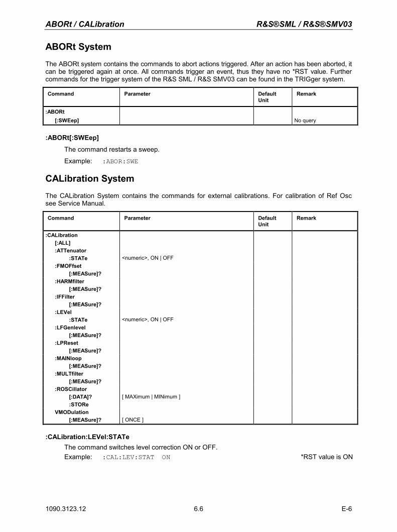
ABORt / CALibration R&S®SML / R&S®SMV03
1090.3123.12 E-6 6.6
ABORt System
The ABORt system contains the commands to abort actions triggered. After an action has been aborted, it can be triggered again at once. All commands trigger an event, thus they have no *RST value. Further commands for the trigger system of the R&S SML / R&S SMV03 can be found in the TRIGger system.
Command Parameter Default Unit
Remark
:ABORt [:SWEep]
No query
:ABORt[:SWEep]
The command restarts a sweep.
Example: :ABOR:SWE
CALibration System
The CALibration System contains the commands for external calibrations. For calibration of Ref Osc see Service Manual. Command Parameter Default
Unit Remark
:CALibration [:ALL]
:ATTenuator :STATe
<numeric>, ON | OFF
:FMOFfset [:MEASure]?
:HARMfilter [:MEASure]?
:IFFilter [:MEASure]?
:LEVel :STATe
<numeric>, ON | OFF
:LFGenlevel [:MEASure]?
:LPReset [:MEASure]?
:MAINloop [:MEASure]?
:MULTfilter [:MEASure]?
:ROSCillator [:DATA]? :STORe
[ MAXimum | MINimum ]
VMODulation [:MEASure]?
[ ONCE ]
:CALibration:LEVel:STATe The command switches level correction ON or OFF. Example: :CAL:LEV:STAT ON *RST value is ON
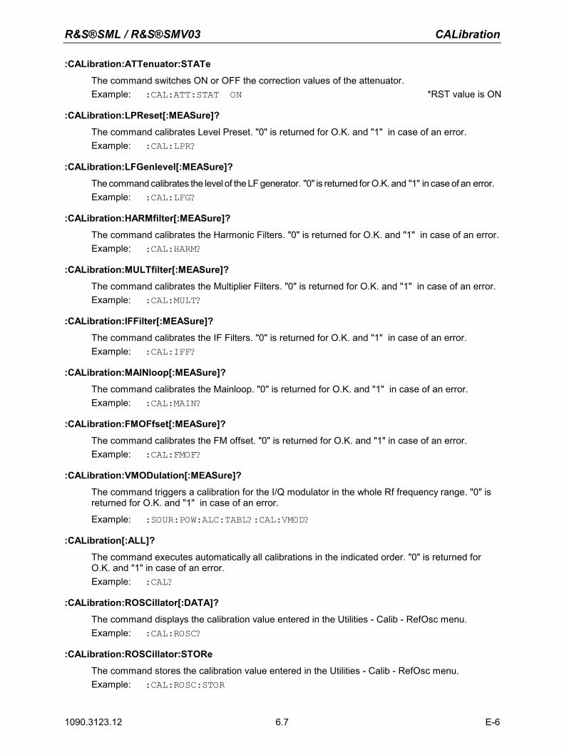
R&S®SML / R&S®SMV03 CALibration
1090.3123.12 E-6 6.7
:CALibration:ATTenuator:STATe
The command switches ON or OFF the correction values of the attenuator. Example: :CAL:ATT:STAT ON *RST value is ON
:CALibration:LPReset[:MEASure]?
The command calibrates Level Preset. "0" is returned for O.K. and "1" in case of an error. Example: :CAL:LPR?
:CALibration:LFGenlevel[:MEASure]?
The command calibrates the level of the LF generator. "0" is returned for O.K. and "1" in case of an error. Example: :CAL:LFG?
:CALibration:HARMfilter[:MEASure]?
The command calibrates the Harmonic Filters. "0" is returned for O.K. and "1" in case of an error. Example: :CAL:HARM?
:CALibration:MULTfilter[:MEASure]?
The command calibrates the Multiplier Filters. "0" is returned for O.K. and "1" in case of an error. Example: :CAL:MULT?
:CALibration:IFFilter[:MEASure]?
The command calibrates the IF Filters. "0" is returned for O.K. and "1" in case of an error. Example: :CAL:IFF?
:CALibration:MAINloop[:MEASure]?
The command calibrates the Mainloop. "0" is returned for O.K. and "1" in case of an error. Example: :CAL:MAIN?
:CALibration:FMOFfset[:MEASure]?
The command calibrates the FM offset. "0" is returned for O.K. and "1" in case of an error. Example: :CAL:FMOF?
:CALibration:VMODulation[:MEASure]?
The command triggers a calibration for the I/Q modulator in the whole Rf frequency range. "0" is returned for O.K. and "1" in case of an error.
Example: :SOUR:POW:ALC:TABL?:CAL:VMOD?
:CALibration[:ALL]?
The command executes automatically all calibrations in the indicated order. "0" is returned for O.K. and "1" in case of an error. Example: :CAL?
:CALibration:ROSCillator[:DATA]?
The command displays the calibration value entered in the Utilities - Calib - RefOsc menu. Example: :CAL:ROSC?
:CALibration:ROSCillator:STORe
The command stores the calibration value entered in the Utilities - Calib - RefOsc menu. Example: :CAL:ROSC:STOR
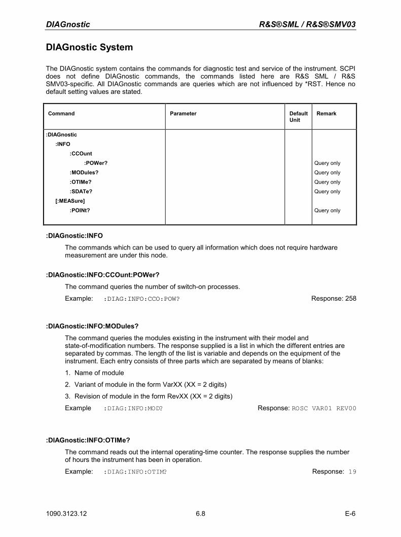
DIAGnostic R&S®SML / R&S®SMV03
1090.3123.12 E-6 6.8
DIAGnostic System
The DIAGnostic system contains the commands for diagnostic test and service of the instrument. SCPI does not define DIAGnostic commands, the commands listed here are R&S SML / R&S SMV03-specific. All DIAGnostic commands are queries which are not influenced by *RST. Hence no default setting values are stated.
Command Parameter Default Unit
Remark
:DIAGnostic
:INFO
:CCOunt
:POWer?
:MODules?
:OTIMe?
:SDATe?
[:MEASure]
:POINt?
Query only
Query only
Query only
Query only
Query only
:DIAGnostic:INFO
The commands which can be used to query all information which does not require hardware measurement are under this node.
:DIAGnostic:INFO:CCOunt:POWer?
The command queries the number of switch-on processes.
Example: :DIAG:INFO:CCO:POW? Response: 258
:DIAGnostic:INFO:MODules?
The command queries the modules existing in the instrument with their model and state-of-modification numbers. The response supplied is a list in which the different entries are separated by commas. The length of the list is variable and depends on the equipment of the instrument. Each entry consists of three parts which are separated by means of blanks:
1. Name of module
2. Variant of module in the form VarXX (XX = 2 digits)
3. Revision of module in the form RevXX (XX = 2 digits)
Example :DIAG:INFO:MOD? Response: ROSC VAR01 REV00
:DIAGnostic:INFO:OTIMe?
The command reads out the internal operating-time counter. The response supplies the number of hours the instrument has been in operation.
Example: :DIAG:INFO:OTIM? Response: 19
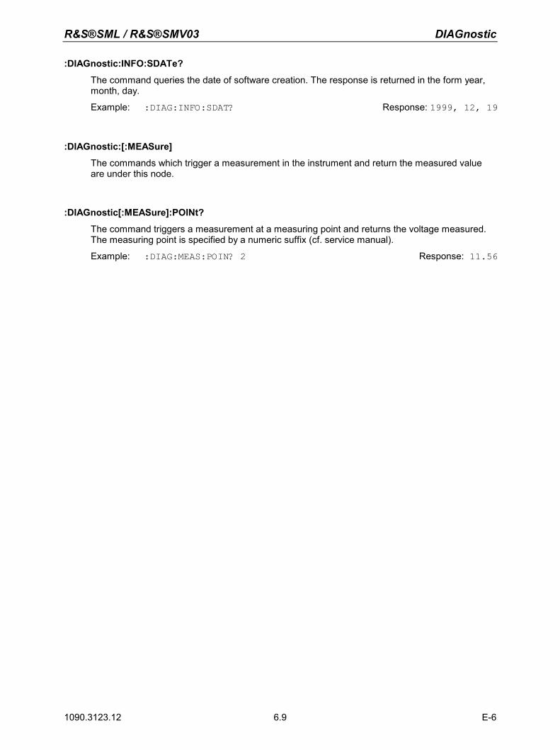
R&S®SML / R&S®SMV03 DIAGnostic
1090.3123.12 E-6 6.9
:DIAGnostic:INFO:SDATe?
The command queries the date of software creation. The response is returned in the form year, month, day.
Example: :DIAG:INFO:SDAT? Response: 1999, 12, 19
:DIAGnostic:[:MEASure]
The commands which trigger a measurement in the instrument and return the measured value are under this node.
:DIAGnostic[:MEASure]:POINt?
The command triggers a measurement at a measuring point and returns the voltage measured. The measuring point is specified by a numeric suffix (cf. service manual).
Example: :DIAG:MEAS:POIN? 2 Response: 11.56
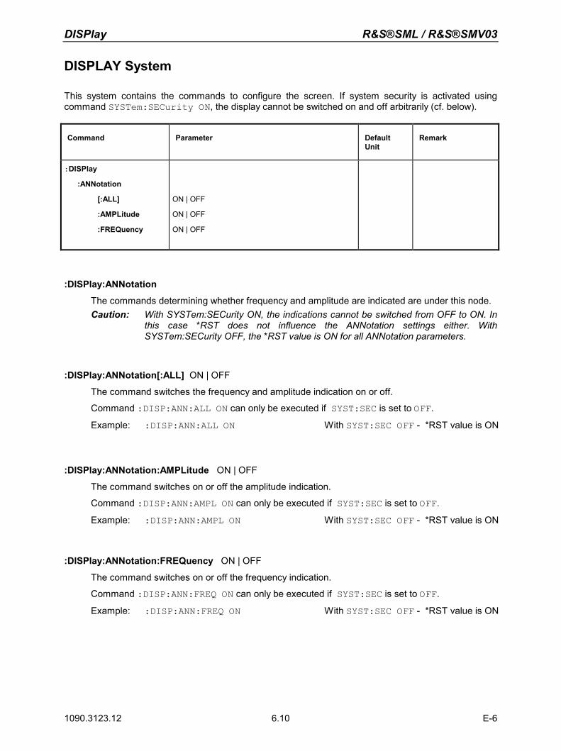
DISPlay R&S®SML / R&S®SMV03
1090.3123.12 E-6 6.10
DISPLAY System
This system contains the commands to configure the screen. If system security is activated using command SYSTem:SECurity ON, the display cannot be switched on and off arbitrarily (cf. below).
Command Parameter Default Unit
Remark
:DISPlay
:ANNotation
[:ALL]
:AMPLitude
:FREQuency
ON | OFF
ON | OFF
ON | OFF
:DISPlay:ANNotation
The commands determining whether frequency and amplitude are indicated are under this node. Caution: With SYSTem:SECurity ON, the indications cannot be switched from OFF to ON. In
this case *RST does not influence the ANNotation settings either. With SYSTem:SECurity OFF, the *RST value is ON for all ANNotation parameters.
:DISPlay:ANNotation[:ALL] ON | OFF
The command switches the frequency and amplitude indication on or off.
Command :DISP:ANN:ALL ON can only be executed if SYST:SEC is set to OFF.
Example: :DISP:ANN:ALL ON With SYST:SEC OFF - *RST value is ON
:DISPlay:ANNotation:AMPLitude ON | OFF
The command switches on or off the amplitude indication.
Command :DISP:ANN:AMPL ON can only be executed if SYST:SEC is set to OFF.
Example: :DISP:ANN:AMPL ON With SYST:SEC OFF - *RST value is ON
:DISPlay:ANNotation:FREQuency ON | OFF
The command switches on or off the frequency indication.
Command :DISP:ANN:FREQ ON can only be executed if SYST:SEC is set to OFF.
Example: :DISP:ANN:FREQ ON With SYST:SEC OFF - *RST value is ON
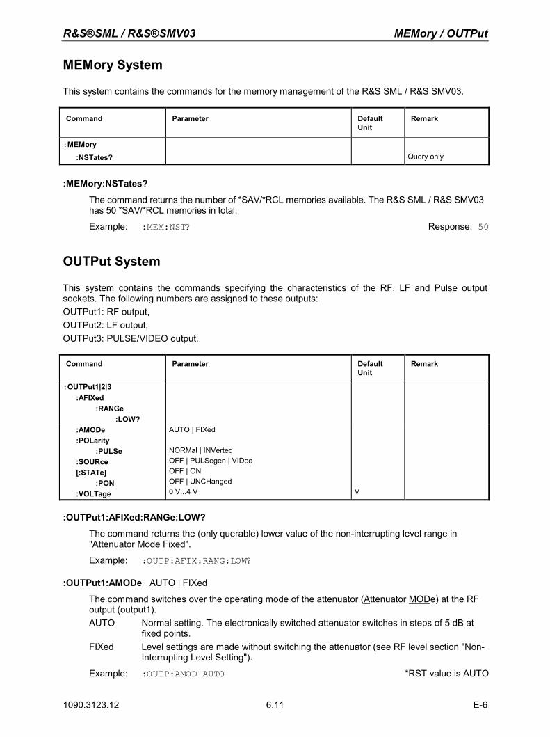
R&S®SML / R&S®SMV03 MEMory / OUTPut
1090.3123.12 E-6 6.11
MEMory System
This system contains the commands for the memory management of the R&S SML / R&S SMV03.
Command Parameter Default Unit
Remark
:MEMory
:NSTates?
Query only
:MEMory:NSTates?
The command returns the number of *SAV/*RCL memories available. The R&S SML / R&S SMV03 has 50 *SAV/*RCL memories in total.
Example: :MEM:NST? Response: 50
OUTPut System
This system contains the commands specifying the characteristics of the RF, LF and Pulse output sockets. The following numbers are assigned to these outputs: OUTPut1: RF output, OUTPut2: LF output, OUTPut3: PULSE/VIDEO output. Command Parameter Default
Unit Remark
:OUTPut1|2|3 :AFIXed :RANGe :LOW?
:AMODe :POLarity :PULSe :SOURce [:STATe] :PON :VOLTage
AUTO | FIXed NORMal | INVerted OFF | PULSegen | VIDeo OFF | ON OFF | UNCHanged 0 V...4 V
V
:OUTPut1:AFIXed:RANGe:LOW?
The command returns the (only querable) lower value of the non-interrupting level range in "Attenuator Mode Fixed".
Example: :OUTP:AFIX:RANG:LOW?
:OUTPut1:AMODe AUTO | FIXed
The command switches over the operating mode of the attenuator (Attenuator MODe) at the RF output (output1). AUTO Normal setting. The electronically switched attenuator switches in steps of 5 dB at
fixed points. FIXed Level settings are made without switching the attenuator (see RF level section "Non-
Interrupting Level Setting").
Example: :OUTP:AMOD AUTO *RST value is AUTO
OUTPut R&S®SML / R&S®SMV03
1090.3123.12 E-6 6.12
:OUTPut3:POLarity:PULSe NORMal | INVerted
The command determines the polarity of the signal at the PULSE/VIDEO output.
Example: :OUTP3:POL:PULS INV *RST value is NORM
:OUTPut3:SOURce OFF | PULSegen | VIDeo
The command selects between pulse generator and video output.
Example: :OUTP3:SOUR VID *RST value is OFF
:OUTPut1|2[:STATe] ON | OFF
The command switches on or off the RF output (output1) or the LF output (output2). The RF output can also be switched off by the response of the protective circuit. But this has no influence on this parameter. Note: In contrast to the PRESET key, command *RST sets the value for output1 to OFF,
the RF-output is deactivated.
Example: :OUTP:STAT ON *RST value is OFF
:OUTPut1[:STATe]:PON OFF | UNCHanged
This command selects the state the RF output (output1) is to assume after power-on of the unit. It only exists for the RF output. *RST does not influence the set value.
OFF Output is switched off
UNCHanged Same state as before switch-off
Example: :OUTP:PON OFF
:OUTPut2:VOLTage 0 V to 4 V
The command sets the voltage of the LF-output (output2). The voltage is a characteristic of the output, not of the source. I.e., the voltage is maintained even if another generator is connected to the output.
Example: :OUTP2:VOLT 3.0V *RST value is 1 V
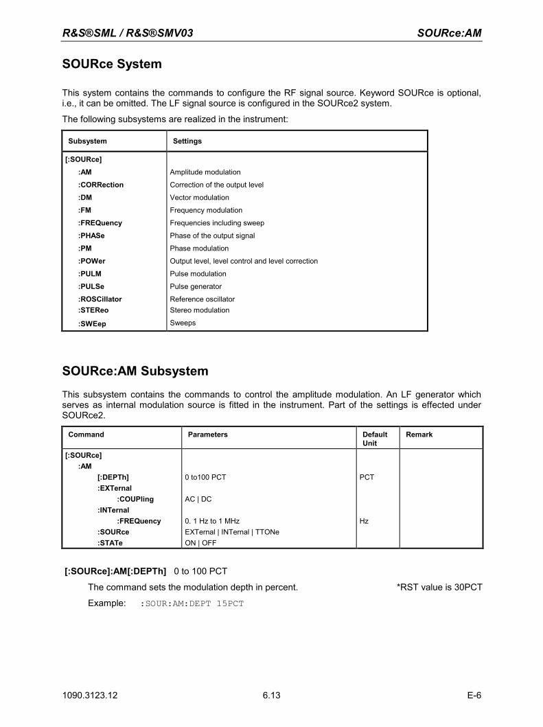
R&S®SML / R&S®SMV03 SOURce:AM
1090.3123.12 E-6 6.13
SOURce System
This system contains the commands to configure the RF signal source. Keyword SOURce is optional, i.e., it can be omitted. The LF signal source is configured in the SOURce2 system.
The following subsystems are realized in the instrument:
Subsystem Settings
[:SOURce]
:AM
:CORRection
:DM
:FM
:FREQuency
:PHASe
:PM
:POWer
:PULM
:PULSe
:ROSCillator :STEReo
:SWEep
Amplitude modulation
Correction of the output level
Vector modulation
Frequency modulation
Frequencies including sweep
Phase of the output signal
Phase modulation
Output level, level control and level correction
Pulse modulation
Pulse generator
Reference oscillator Stereo modulation
Sweeps
SOURce:AM Subsystem
This subsystem contains the commands to control the amplitude modulation. An LF generator which serves as internal modulation source is fitted in the instrument. Part of the settings is effected under SOURce2.
Command Parameters Default Unit
Remark
[:SOURce] :AM [:DEPTh] :EXTernal :COUPling :INTernal :FREQuency :SOURce :STATe
0 to100 PCT AC | DC 0. 1 Hz to 1 MHz EXTernal | INTernal | TTONe ON | OFF
PCT
Hz
[:SOURce]:AM[:DEPTh] 0 to 100 PCT
The command sets the modulation depth in percent. *RST value is 30PCT
Example: :SOUR:AM:DEPT 15PCT
SOURce:AM R&S®SML / R&S®SMV03
1090.3123.12 E-6 6.14
[:SOURce]:AM:EXTernal
The commands to set the external AM input are under this node.
[:SOURce]:AM:EXTernal:COUPling AC | DC
The command selects the type of coupling for the external AM input.
AC The d.c. voltage content is separated from the modulation signal.
DC The modulation signal is not altered. *RST value is AC
Example: :SOUR:AM:EXT:COUP AC
[:SOURce]:AM:INTernal
The settings for the internal AM input are effected under this node.
Here the same hardware is set for AM, FM/M and SOURce2. This means that, for example, the following commands are coupled to each other and have the same effect: SOUR:AM:INT:FREQ SOUR:FM:INT:FREQ SOUR:PM:INT:FREQ SOUR2:FREQ:CW
[:SOURce]:AM:INTernal:FREQuency 0.1Hz to 1 MHz
The command sets the modulation frequency.
Example: :SOUR:AM:INT:FREQ 15kHz *RST value is 1 kHz
[:SOURce]:AM:SOURce EXTernal | INTernal | TTONe
The command selects the modulation source. An external and an internal modulation source can be specified at the same time.
Example: :SOUR:AM:SOUR EXT,INT *RST value is INT *RST value is INT
[:SOURce]:AM:STATe OFF | ON
The command switches amplitude modulation on or off.
Example: :SOUR:AM:STAT ON *RST value is OFF
R&S®SML / R&S®SMV03 SOURce:CORRection
1090.3123.12 E-6 6.15
SOURce:CORRection Subsystem
The CORRection subsystem permits a correction of the output level. The correction is effected by adding user-defined table values to the output level as a function of the RF frequency. In the SML, this subsystem serves to select, transmit and switch on User-Correction tables (see Section "User Correction (Ucor)" as well).
Command Parameters Default Unit
Remark
[:SOURce]
:CORRection
[:STATe]
:CSET
:CATalog?
:FREE?
[:SELect]
:DATA
:FREQuency
:POINts?
:POWer
:POINts?
:DELete :ALL
ON | OFF
"name of table"
9 kHz...Fmax ,9 kHz... Fmax
+20 ... -20dB ,+20 ... -20dB
"name of table"
Hz
dB
Query only
Query only
Fmax depending on model
Query only
Query only
[:SOURce]:CORRection[:STATe] ON | OFF
The command switches the table selected using SOUR:CORR:CSET on or off.
Example: :SOUR:CORR:STAT ON *RST value is OFF
[:SOURce]:CORRection:CSET
The commands to select and edit the Ucor tables are under this node.
[:SOURce]:CORRection:CSET:CATalog?
The command requests a list of Ucor tables. The individual lists are separated by means of commas. This command is a query and has no *RST value.
Example: :SOUR:CORR:CAT? Answer: "UCOR1", "UCOR2", "UCOR3"
[:SOURce]:CORRection:CSET:FREE?
This command queries the free space in the Ucor table.
The command is a query and thus has no *RST value.
Example: :SOUR:CORR:FREE?
SOURce:CORRection R&S®SML / R&S®SMV03
1090.3123.12 E-6 6.16
[:SOURce]:CORRection:CSET[:SELect] "name of table"
The command selects a Ucor table. This command alone does not yet effect a correction. First the table selected must be activated (cf. :SOUR:CORR:STAT). If there is no table of this name, a new table is created. The name may contain up to 7 letters. This command triggers an event and hence has no *RST value.
Example: :SOUR:CORR:CSET:SEL "UCOR1"
[:SOURce]:CORRection:CSET:DATA
The commands to edit the Ucor tables are under this node.
[:SOURce]:CORRection:CSET:DATA:FREQuency 9 kHz... Fmax ,9 kHz... Fmax , Fmax depends on model
The command transmits the frequency data for the table selected using :SOUR:CORR:CSET. The frequency values must be entered in ascending order. *RST does not influence data lists.
Example: :SOUR:CORR:CSET:DATA:FREQ 100MHz,102MHz,103MHz,...
[:SOURce]:CORRection:CSET:DATA:FREQuency:POINts?
The command returns the number of list elements. This command is a query and hence has no *RST value.
Example: :SOUR:CORR:CSET:DATA:FREQ:POIN?
[:SOURce]:CORRection:CSET:DATA:POWer +20 to -20dB ,+20 to -20dB
The command transmits the level data for the table selected using :SOUR:CORR:CSET. *RST does not influence data lists.
Example: :SOUR:CORR:CSET:DATA:POW 1dB, 0.8dB, 0.75dB,...
[:SOURce]:CORRection:CSET:DATA:POWer:POINts?
The command returns the number of list elements. This command is a query and hence has no *RST value.
Example: :SOUR:CORR:CSET:DATA:POW:POIN?
[:SOURce]:CORRection:CSET:DELete "name of table"
The command deletes the table indicated from the instrument memory. This command triggers an event and hence has no *RST value.
Example: :SOUR:CORR:CSET:DEL "UCOR3"
R&S®SML / R&S®SMV03 SOURce:DM
1090.3123.12 E-6 6.17
SOURce:DM Subsystem (R&S SMV03)
This subsystem contains the commands to control the vector modulation and to set the parameters of the modulation signal.
Commandl Parameters Default Unit
Remark
[:SOURce]
:DM
:IMPairment
[:STATe]
:IQ
CREStfactor?
CREStfactor
[:STATe]
ON | OFF
MAXimum | MINimum
<numeric> [ DB ] | MAXimum | MINimum
ON | OFF
:IQRatio [:MAGNitude]
-12 ... +12 PCT
PCT
:IQSWap
[:STATe]
ON | OFF
:LEAKage
[:MAGNitude]
0 ... 50 PCT
PCT
:QUADrature
:ANGLe
-10 ... +10 DEG
DEG
[:SOURce]:DM:IMPairment[:STATe] ON | OFF
The command activates (ON) or deactivates (OFF) the three tuning or correction values LEAKage, QUADrature and IQRatio for vector modulation.
Example: :SOUR:DM:IMP ON *RST value is OFF
[:SOURce]:DM:IQ:CRESTfactor?
The command ask the crestfactor.
Example: :SOUR:DM:IQ:CREST?
[:SOURce]:DM:IQ:CRESTfactor <numeric> [ DB ] | MAXimum | MINimum
The command adjusts the crestfactor.
Example: :SOUR:DM:IQ:CRES 10DB *RST-Wert 0
[:SOURce]:DM:IQ[:STATe] ON | OFF
The command switches the vector modulation on or off,
Example: :SOUR:DM:IQ:STAT ON *RST value is OFF
[:SOURce]:DM:IQRatio:[MAGNitude] -12.0 to 12.0 PCT
The command adjusts the ratio of I and Q modulation (gain balance).
Example: :SOUR:DM:IQR:MAGN -5 PCT *RST value is 0
SOURce:DM R&S®SML / R&S®SMV03
1090.3123.12 E-6 6.18
[:SOURce]:DM:IQSwap[:STATe] ON | OFF
The command interchanges the I and the Q channels in position on.
Example: :SOUR:DM:IQS ON *RST value is OFF
[:SOURce]:DM:LEAKage:[MAGNitude] 0 to 50.0 PCT
The command adjusts the residual carrier amplitude for vector modulation.
Example: :SOUR:DM:LEAK:MAGN 5 PCT *RST value is 0
[:SOURce]:DM:QUADrature:ANGLe
The command changes the quadrature offset for vector modulation.
Example: :SOUR:DM:QUAD:ANGL 4 DEG *RST value is 0
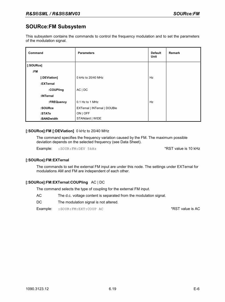
R&S®SML / R&S®SMV03 SOURce:FM
1090.3123.12 E-6 6.19
SOURce:FM Subsystem
This subsystem contains the commands to control the frequency modulation and to set the parameters of the modulation signal.
Command Parameters Default Unit
Remark
[:SOURce]
:FM
[:DEViation]
:EXTernal
:COUPling
:INTernal
:FREQuency
:SOURce
:STATe :BANDwidth
0 kHz to 20/40 MHz
AC | DC
0.1 Hz to 1 MHz
EXTernal | INTernal | DOUBle
ON | OFF STANdard | WIDE
Hz
Hz
[:SOURce]:FM [:DEViation] 0 kHz to 20/40 MHz
The command specifies the frequency variation caused by the FM. The maximum possible deviation depends on the selected frequency (see Data Sheet).
Example: :SOUR:FM:DEV 5kHz *RST value is 10 kHz
[:SOURce]:FM:EXTernal
The commands to set the external FM input are under this node. The settings under EXTernal for modulations AM and FM are independent of each other.
[:SOURce]:FM:EXTernal:COUPling AC | DC
The command selects the type of coupling for the external FM input.
AC The d.c. voltage content is separated from the modulation signal.
DC The modulation signal is not altered.
Example: :SOUR:FM:EXT:COUP AC *RST value is AC
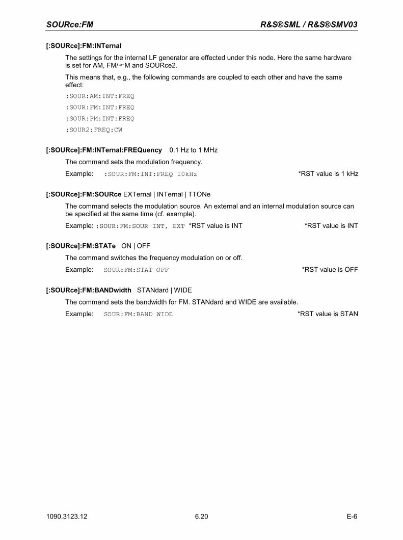
SOURce:FM R&S®SML / R&S®SMV03
1090.3123.12 E-6 6.20
[:SOURce]:FM:INTernal
The settings for the internal LF generator are effected under this node. Here the same hardware is set for AM, FM/M and SOURce2.
This means that, e.g., the following commands are coupled to each other and have the same effect: :SOUR:AM:INT:FREQ :SOUR:FM:INT:FREQ :SOUR:PM:INT:FREQ :SOUR2:FREQ:CW
[:SOURce]:FM:INTernal:FREQuency 0.1 Hz to 1 MHz
The command sets the modulation frequency.
Example: :SOUR:FM:INT:FREQ 10kHz *RST value is 1 kHz
[:SOURce]:FM:SOURce EXTernal | INTernal | TTONe
The command selects the modulation source. An external and an internal modulation source can be specified at the same time (cf. example).
Example: :SOUR:FM:SOUR INT, EXT *RST value is INT *RST value is INT
[:SOURce]:FM:STATe ON | OFF
The command switches the frequency modulation on or off.
Example: SOUR:FM:STAT OFF *RST value is OFF
[:SOURce]:FM:BANDwidth STANdard | WIDE
The command sets the bandwidth for FM. STANdard and WIDE are available.
Example: SOUR:FM:BAND WIDE *RST value is STAN
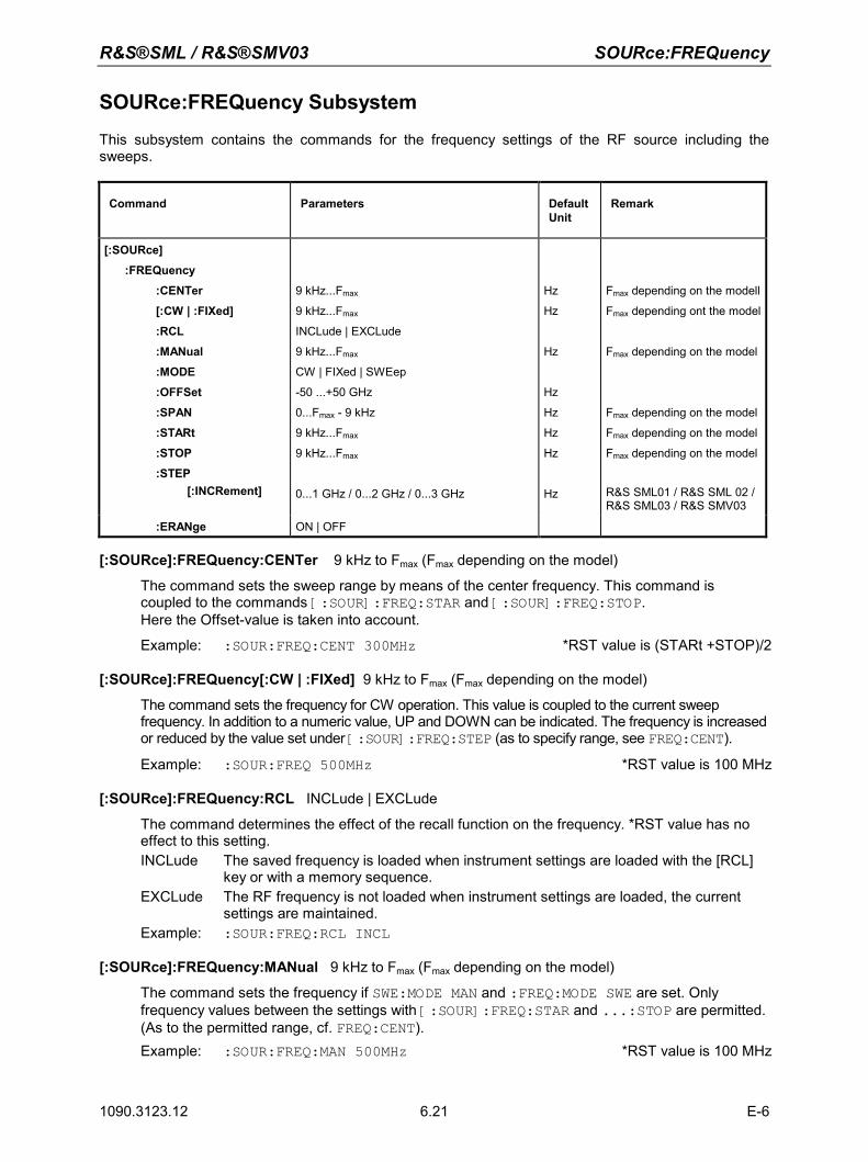
R&S®SML / R&S®SMV03 SOURce:FREQuency
1090.3123.12 E-6 6.21
SOURce:FREQuency Subsystem
This subsystem contains the commands for the frequency settings of the RF source including the sweeps.
Command Parameters Default Unit
Remark
[:SOURce]
:FREQuency
:CENTer
[:CW | :FIXed]
:RCL
:MANual
:MODE
:OFFSet
:SPAN
:STARt
:STOP
:STEP [:INCRement]
9 kHz...Fmax
9 kHz...Fmax
INCLude | EXCLude
9 kHz...Fmax
CW | FIXed | SWEep
-50 ...+50 GHz
0...Fmax - 9 kHz
9 kHz...Fmax
9 kHz...Fmax
0...1 GHz / 0...2 GHz / 0...3 GHz
Hz
Hz
Hz
Hz
Hz
Hz
Hz
Hz
Fmax depending on the modell
Fmax depending ont the model
Fmax depending on the model
Fmax depending on the model
Fmax depending on the model
Fmax depending on the model
R&S SML01 / R&S SML 02 / R&S SML03 / R&S SMV03
:ERANge ON | OFF
[:SOURce]:FREQuency:CENTer 9 kHz to Fmax (Fmax depending on the model)
The command sets the sweep range by means of the center frequency. This command is coupled to the commands [:SOUR]:FREQ:STAR and [:SOUR]:FREQ:STOP.Here the Offset-value is taken into account.
Example: :SOUR:FREQ:CENT 300MHz *RST value is (STARt +STOP)/2
[:SOURce]:FREQuency[:CW | :FIXed] 9 kHz to Fmax (Fmax depending on the model)
The command sets the frequency for CW operation. This value is coupled to the current sweep frequency. In addition to a numeric value, UP and DOWN can be indicated. The frequency is increased or reduced by the value set under [:SOUR]:FREQ:STEP (as to specify range, see FREQ:CENT).
Example: :SOUR:FREQ 500MHz *RST value is 100 MHz
[:SOURce]:FREQuency:RCL INCLude | EXCLude
The command determines the effect of the recall function on the frequency. *RST value has no effect to this setting. INCLude The saved frequency is loaded when instrument settings are loaded with the [RCL]
key or with a memory sequence. EXCLude The RF frequency is not loaded when instrument settings are loaded, the current
settings are maintained. Example: :SOUR:FREQ:RCL INCL
[:SOURce]:FREQuency:MANual 9 kHz to Fmax (Fmax depending on the model)
The command sets the frequency if SWE:MODE MAN and :FREQ:MODE SWE are set. Only frequency values between the settings with [:SOUR]:FREQ:STAR and ...:STOP are permitted. (As to the permitted range, cf. FREQ:CENT). Example: :SOUR:FREQ:MAN 500MHz *RST value is 100 MHz
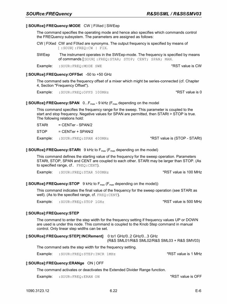
SOURce:FREQuency R&S®SML / R&S®SMV03
1090.3123.12 E-6 6.22
[:SOURce]:FREQuency:MODE CW | FIXed | SWEep
The command specifies the operating mode and hence also specifies which commands control the FREQuency subsystem. The parameters are assigned as follows:
CW | FIXed CW and FIXed are synonyms. The output frequency is specified by means of [:SOUR]:FREQ:CW | FIX.
SWEep The instrument operates in the SWEep-mode. The frequency is specified by means of commands [:SOUR]:FREQ:STAR; STOP; CENT; SPAN; MAN.
Example: :SOUR:FREQ:MODE SWE *RST value is CW
[:SOURce]:FREQuency:OFFSet -50 to +50 GHz
The command sets the frequency offset of a mixer which might be series-connected (cf. Chapter 4, Section "Frequency Offset").
Example: :SOUR:FREQ:OFFS 100MHz *RST value is 0
[:SOURce]:FREQuency:SPAN 0...Fmax - 9 kHz (Fmax depending on the model
This command specifies the frequency range for the sweep. This parameter is coupled to the start and stop frequency. Negative values for SPAN are permitted, then STARt > STOP is true. The following relations hold:
STARt = CENTer - SPAN/2
STOP = CENTer + SPAN/2
Example: :SOUR:FREQ:SPAN 400MHz *RST value is (STOP - STARt)
[:SOURce]:FREQuency:STARt 9 kHz to Fmax (Fmax depending on the model)
This command defines the starting value of the frequency for the sweep operation. Parameters STARt, STOP, SPAN and CENT are coupled to each other. STARt may be larger than STOP. (As to specified range, cf. FREQ:CENT).
Example: :SOUR:FREQ:STAR 500MHz *RST value is 100 MHz
[:SOURce]:FREQuency:STOP 9 kHz to Fmax (Fmax depending on the model))
This command indicates the final value of the frequency for the sweep operation (see STARt as well). (As to the specified range, cf. FREQ:CENT).
Example: :SOUR:FREQ:STOP 1GHz *RST value is 500 MHz
[:SOURce]:FREQuency:STEP
The command to enter the step width for the frequency setting if frequency values UP or DOWN are used is under this node. This command is coupled to the Knob Step command in manual control. Only linear step widths can be set.
[:SOURce]:FREQuency:STEP[:INCRement] 0 to1 GHz/0..2 GHz/0...3 GHz (R&S SML01/R&S SML02/R&S SML03 + R&S SMV03)
The command sets the step width for the frequency setting.
Example: :SOUR:FREQ:STEP:INCR 1MHz *RST value is 1 MHz
[:SOURce]:FREQuency:ERANge ON | OFF
The command activates or deactivates the Extended Divider Range function.
Example: :SOUR:FREQ:ERAN ON *RST value is OFF
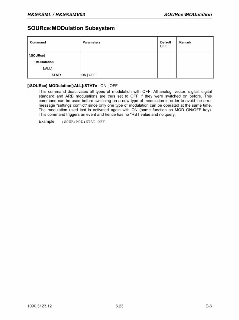
R&S®SML / R&S®SMV03 SOURce:MODulation
1090.3123.12 E-6 6.23
SOURce:MODulation Subsystem
Command Parameters Default Unit
Remark
[:SOURce]
:MODulation
[:ALL]
STATe
ON | OFF
[:SOURce]:MODulation[:ALL]:STATe ON | OFF This command deactivates all types of modulation with OFF. All analog, vector, digital, digital standard and ARB modulations are thus set to OFF if they were switched on before. This command can be used before switching on a new type of modulation in order to avoid the error message "settings conflict" since only one type of modulation can be operated at the same time. The modulation used last is activated again with ON (same function as MOD ON/OFF key). This command triggers an event and hence has no *RST value and no query.
Example: :SOUR:MOD:STAT OFF
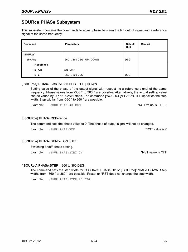
SOURce:PHASe R&S SML
1090.3123.12 E-6 6.24
SOURce:PHASe Subsystem
This subsystem contains the commands to adjust phase between the RF output signal and a reference signal of the same frequency.
Command Parameters Default Unit
Remark
[:SOURce]
:PHASe
-360 ... 360 DEG | UP | DOWN
DEG
:REFerence
:STATe
ON | OFF
:STEP -360 ... 360 DEG DEG
[:SOURce]:PHASe -360 to 360 DEG | UP | DOWN Setting value of the phase of the output signal with respect to a reference signal of the same frequency. Phase values from -360 ° to 360 ° are possible. Alternatively, the actual setting value can be varied by UP or DOWN steps. The command [:SOURCE]:PHASe:STEP specifies the step width. Step widths from -360 ° to 360 ° are possible.
Example: :SOUR:PHAS 40 DEG *RST value is 0 DEG
[:SOURce]:PHASe:REFerence
The command sets the phase value to 0. The phase of output signal will not be changed.
Example: :SOUR:PHAS:REF *RST value is 0
[:SOURce]:PHASe:STATe ON | OFF
Switching on/off phase setting.
Example: :SOUR:PHAS:STAT ON *RST value is OFF
[:SOURce]:PHASe:STEP -360 to 360 DEG The command sets the step width for [:SOURce]:PHASe UP or [:SOURce]:PHASe DOWN. Step widths from -360 ° to 360 ° are possible. Preset or *RST does not change the step width.
Example: :SOUR:PHAS:STEP 90 DEG
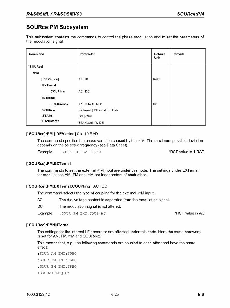
R&S®SML / R&S®SMV03 SOURce:PM
1090.3123.12 E-6 6.25
SOURce:PM Subsystem
This subsystem contains the commands to control the phase modulation and to set the parameters of the modulation signal.
Command Parameter Default Unit
Remark
[:SOURce]
:PM
[:DEViation]
:EXTernal
:COUPling
:INTernal
:FREQuency
:SOURce
:STATe :BANDwidth
0 to 10
AC | DC
0.1 Hz to 10 MHz
EXTernal | INTernal | TTONe
ON | OFF
STANdard | WIDE
RAD
Hz
[:SOURce]:PM [:DEViation] 0 to 10 RAD
The command specifies the phase variation caused by the M. The maximum possible deviation depends on the selected frequency (see Data Sheet).
Example: :SOUR:PM:DEV 2 RAD *RST value is 1 RAD
[:SOURce]:PM:EXTernal
The commands to set the external M input are under this node. The settings under EXTernal for modulations AM, FM and M are independent of each other.
[:SOURce]:PM:EXTernal:COUPling AC | DC
The command selects the type of coupling for the external M input.
AC The d.c. voltage content is separated from the modulation signal.
DC The modulation signal is not altered.
Example: :SOUR:PM:EXT:COUP AC *RST value is AC
[:SOURce]:PM:INTernal
The settings for the internal LF generator are effected under this node. Here the same hardware is set for AM, FM/M and SOURce2.
This means that, e.g., the following commands are coupled to each other and have the same effect: :SOUR:AM:INT:FREQ :SOUR:FM:INT:FREQ :SOUR:PM:INT:FREQ :SOUR2:FREQ:CW
SOURce:PM R&S®SML / R&S®SMV03
1090.3123.12 E-6 6.26
[:SOURce]:PM:INTernal:FREQuency 0.1 Hz to 10 MHz
The command sets the modulation frequency.
Example: :SOUR:PM:INT:FREQ 10kHz *RST value is 1 kHz
[:SOURce]:PM:SOURce EXTernal | INTernal | TTONe
The command selects the modulation source. An external and an internal modulation source can be specified at the same time (cf. example).
Example: :SOUR:PM:SOUR INT *RST value is INT
[:SOURce]:PM:STATe ON | OFF
The command switches the phase modulation on or off.
Example: SOUR:PM:STAT OFF *RST value is OFF
[:SOURce]:PM:BANDwidth STANdard | WIDE
The command sets the bandwidth for M. STANdard and WIDE are available.
Example: SOUR:PM:BAND WIDE *RST value is STAN
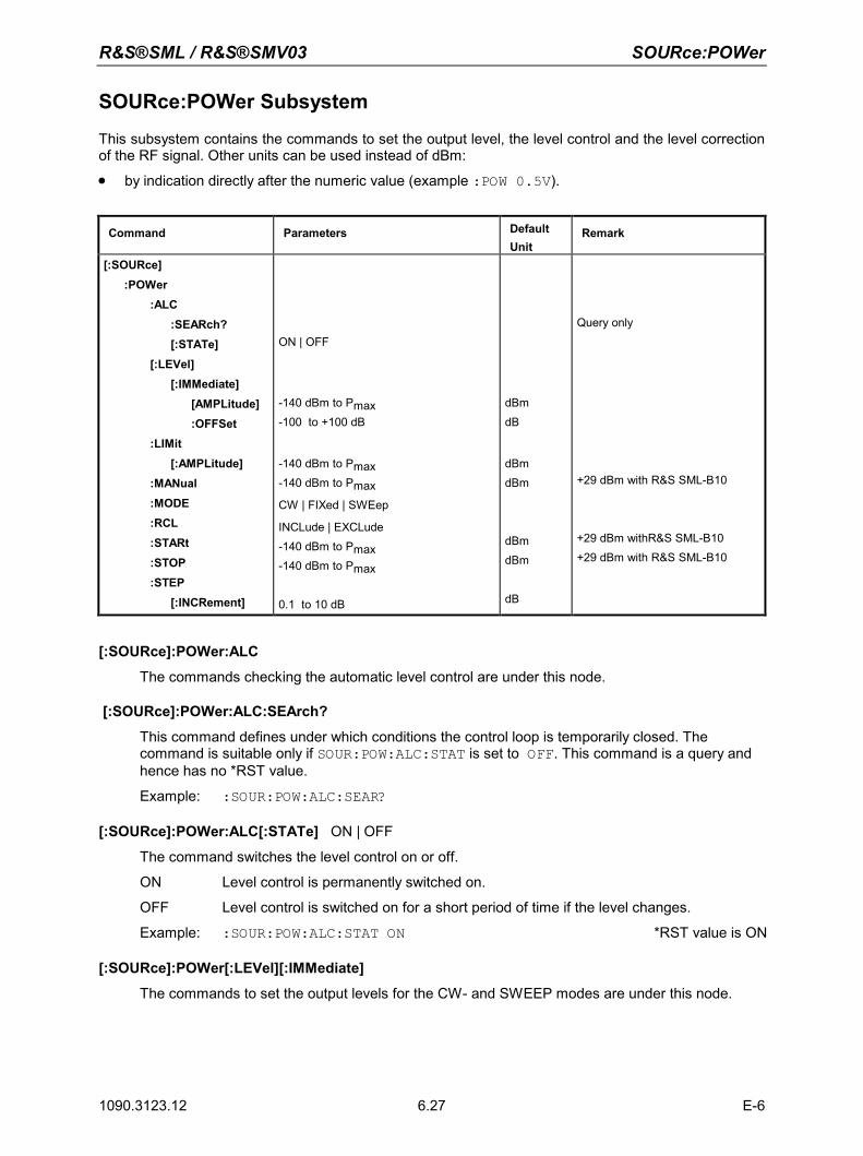
R&S®SML / R&S®SMV03 SOURce:POWer
1090.3123.12 E-6 6.27
SOURce:POWer Subsystem
This subsystem contains the commands to set the output level, the level control and the level correction of the RF signal. Other units can be used instead of dBm: • by indication directly after the numeric value (example :POW 0.5V).
Command Parameters Default Unit
Remark
[:SOURce] :POWer :ALC :SEARch? [:STATe] [:LEVel] [:IMMediate] [AMPLitude] :OFFSet :LIMit [:AMPLitude] :MANual :MODE :RCL :STARt :STOP :STEP [:INCRement]
ON | OFF
-140 dBm to Pmax -100 to +100 dB
-140 dBm to Pmax -140 dBm to Pmax
CW | FIXed | SWEep
INCLude | EXCLude -140 dBm to Pmax -140 dBm to Pmax
0.1 to 10 dB
dBm dB
dBm dBm
dBm dBm dB
Query only
+29 dBm with R&S SML-B10
+29 dBm withR&S SML-B10 +29 dBm with R&S SML-B10
[:SOURce]:POWer:ALC
The commands checking the automatic level control are under this node.
[:SOURce]:POWer:ALC:SEArch?
This command defines under which conditions the control loop is temporarily closed. The command is suitable only if SOUR:POW:ALC:STAT is set to OFF. This command is a query and hence has no *RST value.
Example: :SOUR:POW:ALC:SEAR?
[:SOURce]:POWer:ALC[:STATe] ON | OFF
The command switches the level control on or off.
ON Level control is permanently switched on.
OFF Level control is switched on for a short period of time if the level changes.
Example: :SOUR:POW:ALC:STAT ON *RST value is ON
[:SOURce]:POWer[:LEVel][:IMMediate]
The commands to set the output levels for the CW- and SWEEP modes are under this node.
SOURce:POWer R&S®SML / R&S®SMV03
1090.3123.12 E-6 6.28
[:SOURce]:POWer[:LEVel][:IMMediate][:AMPLitude] -140 dBm to Pmax (+29 dBm with R&S SML-B10)
The command sets the RF output level in operating mode CW. UP and DOWN can be indicated in addition to numeric values. Then the level is increased or reduced by the value indicated under [:SOUR]:POW:STEP.In this command, the OFFSet value is considered. Thus the specified range indicated is only valid for :SOUR:POW:OFFS 0.
The keywords of this command are optional to a large extent, thus the long as well as the short form of the command is shown in the example.
Example: :SOUR:POW:LEV:IMM:AMPL -10 or :POW –10 *RST value is -30 dBm
[:SOURce]:POWer[:LEVel][:IMMediate][:AMPLitude]:OFFSet -100 to +100 dB
The command enters the constant level offset of a series-connected attenuator/ amplifier (cf. Chapter 4, Section "Level Offset"). If a level offset is entered, the level entered using :POW does no longer conform to the RF output level. The following relation is true: :POW = RF output level + :POW:OFFS Entering a level offset does not change the RF output level but only the value queried by :POW.The level offset is also valid for level sweep! Only dB is permissible as a unit here, linear units (V, W etc.) are not permitted.
Example: :SOUR:POW:LEV:IMM:AMPL:OFFS 0 or :POW:OFFS 0 *RST value is 0 dB
[:SOURce]:POWer:LIMit[:AMPLitude] -140 dBm to Pmax (+29 dBm with R&S SML-B10)
The command limits the maximum RF output level in operating mode CW and SWEEP. It does not influence the display LEVEL and the answer to query POW?.
Example: :SOUR:POW:LIM:AMPL 19 not influenced by *RST
[:SOURce]:POWer:MANual -140 dBm to Pmax (+29 dBm with R&S SML-B10)
The command sets the level if SOUR:POW:MODE is set to :SWE and SOUR:SWE:MODE to MAN.Only level values between STARt and STOP are permitted (as to specified range, cf. :POW:AMPL).
Example: :SOUR:POW:MAN 1dBm *RST value is -30 dBm
[:SOURce]:POWer:MODE CW | FIXed | SWEep
The command specifies the operating mode and thus also by means of which commands the level setting is checked. CW | FIXed The output level is specified by means of commands under [:SOUR]:POW:LEV.SWEep The instrument operates in the SWEep mode. The level is specified by means of
[:SOUR]:POW; STAR; STOP; CENT; SPAN and MAN.
Example: :SOUR:POW:MODE FIX *RST value is FIX
[:SOURce]:POWer:RCL INCLude | EXCLude
INCLude The stored RF level is loaded too when instrument settings are loaded.
EXCLude The stored RF level is not loaded when instrument settings are loaded ie the current level setting is maintained.
Example: :SOUR:POW:RCL INCL not influenced by *RST
R&S®SML / R&S®SMV03 SOURce:POWer
1090.3123.12 E-6 6.29
[:SOURce]:POWer:STARt -140 dBm to Pmax (+29 dBm with R&S SML-B10)
The command sets the staring value for a level sweep. STARt may be larger than STOP, then the sweep runs from the high to the low level (As to specified range, cf. :POW).
Example: :SOUR:POW:STAR -20 *RST value is -30 dBm
[:SOURce]:POWer:STOP -140 dBm to Pmax (+29 dBm with R&S SML-B10)
The command sets the final value for a level sweep. STOP may be smaller than STARt. (As to specified range, cf. :POW).
Example: :SOUR:POW:STOP 3 *RST value is -10dBm
[:SOURce]:POWer:STEP[:INCRement] 0.1 to 10 dB
The command sets the step width with the level setting if UP and DOWN are used as level values. The command is coupled to Knob Step in the manual control, i.e., it also specifies the step width of the shaft encoder.
Only dB is permissible as a unit here, the linear units (V, W etc.) are not permitted.
Example: :SOUR:POW:STEP:INCR 2 *RST value is 1dB
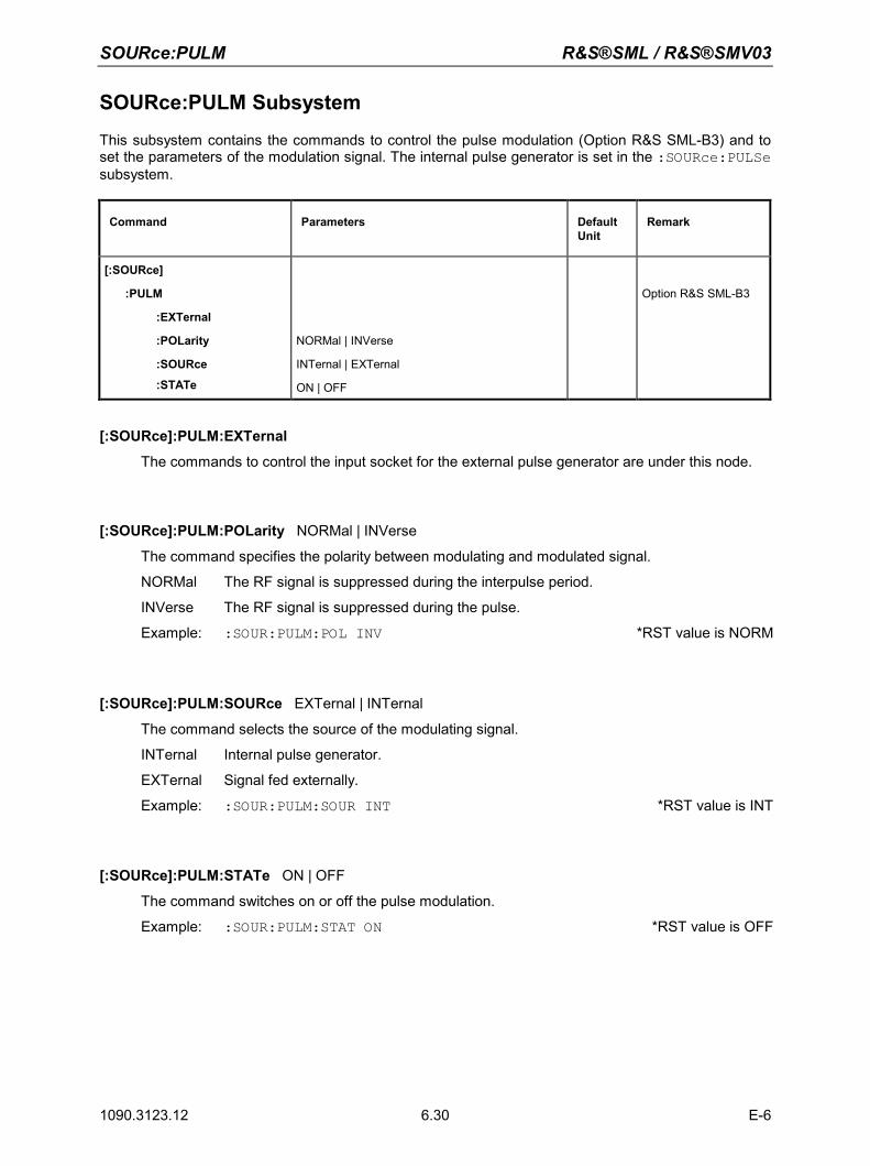
SOURce:PULM R&S®SML / R&S®SMV03
1090.3123.12 E-6 6.30
SOURce:PULM Subsystem
This subsystem contains the commands to control the pulse modulation (Option R&S SML-B3) and to set the parameters of the modulation signal. The internal pulse generator is set in the :SOURce:PULSe subsystem.
Command Parameters Default Unit
Remark
[:SOURce]
:PULM
:EXTernal
:POLarity
:SOURce
:STATe
NORMal | INVerse
INTernal | EXTernal
ON | OFF
Option R&S SML-B3
[:SOURce]:PULM:EXTernal
The commands to control the input socket for the external pulse generator are under this node.
[:SOURce]:PULM:POLarity NORMal | INVerse
The command specifies the polarity between modulating and modulated signal.
NORMal The RF signal is suppressed during the interpulse period.
INVerse The RF signal is suppressed during the pulse.
Example: :SOUR:PULM:POL INV *RST value is NORM
[:SOURce]:PULM:SOURce EXTernal | INTernal
The command selects the source of the modulating signal.
INTernal Internal pulse generator.
EXTernal Signal fed externally.
Example: :SOUR:PULM:SOUR INT *RST value is INT
[:SOURce]:PULM:STATe ON | OFF
The command switches on or off the pulse modulation.
Example: :SOUR:PULM:STAT ON *RST value is OFF
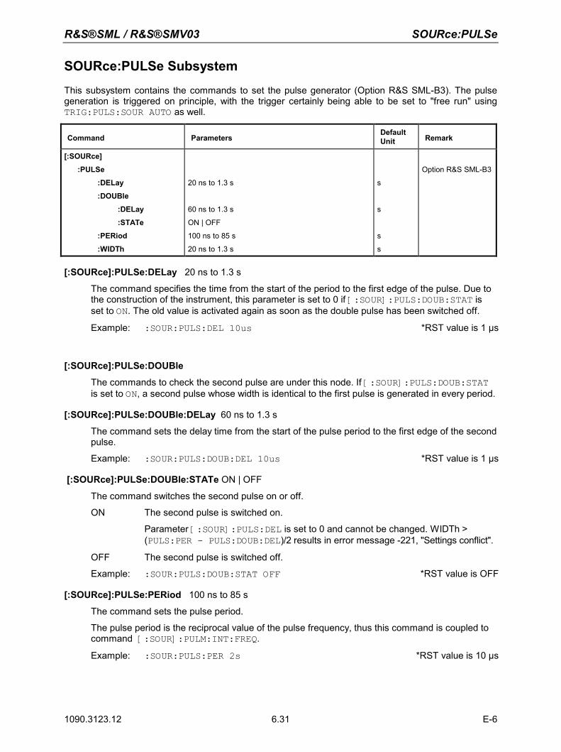
R&S®SML / R&S®SMV03 SOURce:PULSe
1090.3123.12 E-6 6.31
SOURce:PULSe Subsystem
This subsystem contains the commands to set the pulse generator (Option R&S SML-B3). The pulse generation is triggered on principle, with the trigger certainly being able to be set to "free run" using TRIG:PULS:SOUR AUTO as well.
Command Parameters Default Unit Remark
[:SOURce]
:PULSe
:DELay
:DOUBle
:DELay
:STATe
:PERiod
:WIDTh
20 ns to 1.3 s
60 ns to 1.3 s
ON | OFF
100 ns to 85 s
20 ns to 1.3 s
s
s
s
s
Option R&S SML-B3
[:SOURce]:PULSe:DELay 20 ns to 1.3 s
The command specifies the time from the start of the period to the first edge of the pulse. Due to the construction of the instrument, this parameter is set to 0 if [:SOUR]:PULS:DOUB:STAT is set to ON. The old value is activated again as soon as the double pulse has been switched off.
Example: :SOUR:PULS:DEL 10us *RST value is 1 µs
[:SOURce]:PULSe:DOUBle
The commands to check the second pulse are under this node. If [:SOUR]:PULS:DOUB:STAT is set to ON, a second pulse whose width is identical to the first pulse is generated in every period.
[:SOURce]:PULSe:DOUBle:DELay 60 ns to 1.3 s
The command sets the delay time from the start of the pulse period to the first edge of the second pulse.
Example: :SOUR:PULS:DOUB:DEL 10us *RST value is 1 µs
[:SOURce]:PULSe:DOUBle:STATe ON | OFF
The command switches the second pulse on or off.
ON The second pulse is switched on.
Parameter [:SOUR]:PULS:DEL is set to 0 and cannot be changed. WIDTh > (PULS:PER - PULS:DOUB:DEL)/2 results in error message -221, "Settings conflict".
OFF The second pulse is switched off.
Example: :SOUR:PULS:DOUB:STAT OFF *RST value is OFF
[:SOURce]:PULSe:PERiod 100 ns to 85 s
The command sets the pulse period.
The pulse period is the reciprocal value of the pulse frequency, thus this command is coupled to command [:SOUR]:PULM:INT:FREQ.
Example: :SOUR:PULS:PER 2s *RST value is 10 µs
SOURce:PULSe R&S®SML / R&S®SMV03
1090.3123.12 E-6 6.32
[:SOURce]:PULSe:WIDTh 20 ns to 1.3 s
The command sets the pulse width.
Example: :SOUR:PULS:WIDT 0.1s *RST value is 1 µs
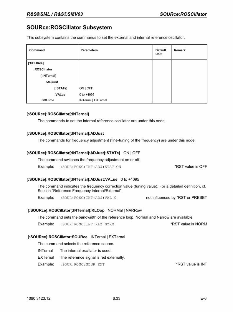
R&S®SML / R&S®SMV03 SOURce:ROSCillator
1090.3123.12 E-6 6.33
SOURce:ROSCillator Subsystem
This subsystem contains the commands to set the external and internal reference oscillator.
Command Parameters Default Unit
Remark
[:SOURce]
:ROSCillator
[:INTernal]
:ADJust
[:STATe]
:VALue
:SOURce
ON | OFF
0 to +4095
INTernal | EXTernal
[:SOURce]:ROSCillator[:INTernal]
The commands to set the internal reference oscillator are under this node.
[:SOURce]:ROSCillator[:INTernal]:ADJust
The commands for frequency adjustment (fine-tuning of the frequency) are under this node.
[:SOURce]:ROSCillator[:INTernal]:ADJust[:STATe] ON | OFF
The command switches the frequency adjustment on or off.
Example: :SOUR:ROSC:INT:ADJ:STAT ON *RST value is OFF
[:SOURce]:ROSCillator[:INTernal]:ADJust:VALue 0 to +4095
The command indicates the frequency correction value (tuning value). For a detailed definition, cf. Section "Reference Frequency Internal/External".
Example: :SOUR:ROSC:INT:ADJ:VAL 0 not influenced by *RST or PRESET
[:SOURce]:ROSCillator[:INTernal]:RLOop NORMal | NARRow
The command sets the bandwidth of the reference loop. Normal and Narrow are available.
Example: :SOUR:ROSC:INT:RLO NORM *RST value is NORM
[:SOURce]:ROSCillator:SOURce INTernal | EXTernal
The command selects the reference source.
INTernal The internal oscillator is used.
EXTernal The reference signal is fed externally.
Example: :SOUR:ROSC:SOUR EXT *RST value is INT
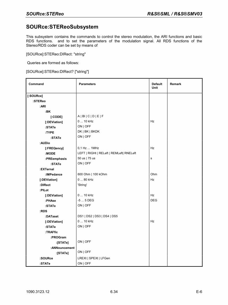
SOURce:STEReo R&S®SML / R&S®SMV03
1090.3123.12 E-6 6.34
SOURce:STEReoSubsystem
This subsystem contains the commands to control the stereo modulation, the ARI functions and basic RDS functions. and to set the parameters of the modulation signal. All RDS functions of the Stereo/RDS coder can be set by means of [SOURce]:STEReo:DIRect: "string" Queries are formed as follows: [SOURce]:STEReo:DIRect? ["string"]
Command Parameters Default Unit
Remark
[:SOURce] :STEReo :ARI :BK [:CODE] [:DEViation] :STATe :TYPE :STATe
A | Bl | C | D | E | F 0 ... 10 kHz ON | OFF DK | BK | BKDK ON | OFF
Hz
:AUDio [:FREQency] :MODE :PREemphasis :STATe
0,1 Hz ... 1MHz LEFT | RIGHt | RELeft | REMLeft| RNELeft 50 us | 75 us ON | OFF
Hz s
:EXTernal :IMPedance
600 Ohm | 100 kOhm
Ohm
[:DEViation] 0 ... 80 kHz Hz
:DIRect 'String'
:PILot [:DEViation] :PHAse :STATe
0 ... 10 kHz -5 ... 5 DEG ON | OFF
Hz DEG
:RDS :DATaset [:DEViation] :STATe :TRAFfic :PROGram :[STATe] :ANNouncement :[STATe]
DS1 | DS2 | DS3 | DS4 | DS5 0 ... 10 kHz ON | OFF
ON | OFF ON | OFF
Hz
:SOURce LREXt | SPEXt | LFGen
:STATe ON | OFF
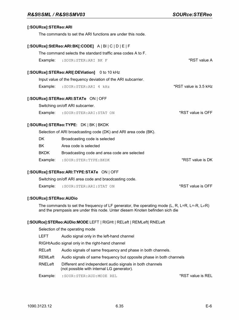
R&S®SML / R&S®SMV03 SOURce:STEReo
1090.3123.12 E-6 6.35
[:SOURce]:STEReo:ARI
The commands to set the ARI functions are under this node.
[:SOURce]:StEReo:ARI:BK[:CODE] A | Bl | C | D | E | F
The command selects the standard traffic area codes A to F.
Example: :SOUR:STER:ARI BK F *RST value A
[:SOURce]:STEReo:ARI[:DEViation] 0 to 10 kHz
Input value of the frequency deviation of the ARI subcarrier.
Example: :SOUR:STER:ARI 4 kHz *RST value is 3.5 kHz
[:SOURce]:STEReo:ARI:STATe ON | OFF
Switching on/off ARI subcarrier.
Example: :SOUR:STER:ARI:STAT ON *RST value is OFF
[:SOURce]:STEReo:TYPE: DK | BK | BKDK
Selection of ARI broadcasting code (DK) and ARI area code (BK).
DK Broadcasting code is selected
BK Area code is selected
BKDK Broadcasting code and area code are selected
Example: :SOUR:STER:TYPE:BKDK *RST value is DK
[:SOURce]:STEReo:ARI:TYPE:STATe ON | OFF
Switching on/off ARI area code and braodcasting code.
Example: :SOUR:STER:ARI:STAT ON *RST value is OFF
[:SOURce]:STEReo:AUDio
The commands to set the frequency of LF generator, the operating mode (L, R, L=R, L=-R, L≠R) and the prempasis are under this node. Unter diesem Knoten befinden sich die
[:SOURce]:STEReo:AUDio:MODE LEFT | RIGHt | RELeft | REMLeft| RNELeft
Selection of the operating mode
LEFT Audio signal only in the left-hand channel
RIGHt Audio signal only in the right-hand channel
RELeft Audio signals of same frequency and phase in both channels.
REMLeft Audio signals of same frequency but opposite phase in both channels
RNELeft Different and independent audio signals in both channels (not possible with internal LG generator).
Example: :SOUR:STER:AUD:MODE REL *RST value is REL
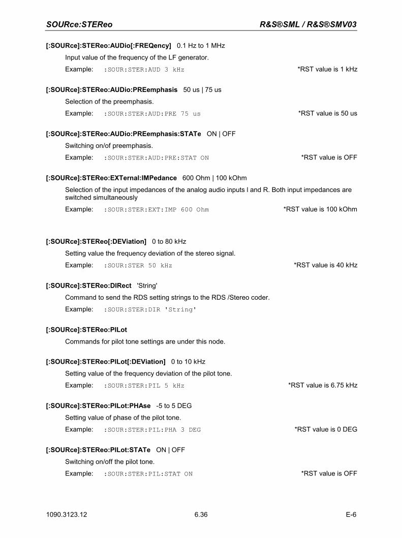
SOURce:STEReo R&S®SML / R&S®SMV03
1090.3123.12 E-6 6.36
[:SOURce]:STEReo:AUDio[:FREQency] 0.1 Hz to 1 MHz
Input value of the frequency of the LF generator.
Example: :SOUR:STER:AUD 3 kHz *RST value is 1 kHz
[:SOURce]:STEReo:AUDio:PREemphasis 50 us | 75 us
Selection of the preemphasis.
Example: :SOUR:STER:AUD:PRE 75 us *RST value is 50 us
[:SOURce]:STEReo:AUDio:PREemphasis:STATe ON | OFF
Switching on/of preemphasis.
Example: :SOUR:STER:AUD:PRE:STAT ON *RST value is OFF
[:SOURce]:STEReo:EXTernal:IMPedance 600 Ohm | 100 kOhm
Selection of the input impedances of the analog audio inputs l and R. Both input impedances are switched simultaneously
Example: :SOUR:STER:EXT:IMP 600 Ohm *RST value is 100 kOhm
[:SOURce]:STEReo[:DEViation] 0 to 80 kHz
Setting value the frequency deviation of the stereo signal.
Example: :SOUR:STER 50 kHz *RST value is 40 kHz
[:SOURce]:STEReo:DIRect 'String'
Command to send the RDS setting strings to the RDS /Stereo coder.
Example: :SOUR:STER:DIR 'String'
[:SOURce]:STEReo:PILot
Commands for pilot tone settings are under this node.
[:SOURce]:STEReo:PILot[:DEViation] 0 to 10 kHz
Setting value of the frequency deviation of the pilot tone.
Example: :SOUR:STER:PIL 5 kHz *RST value is 6.75 kHz
[:SOURce]:STEReo:PILot:PHAse -5 to 5 DEG
Setting value of phase of the pilot tone.
Example: :SOUR:STER:PIL:PHA 3 DEG *RST value is 0 DEG
[:SOURce]:STEReo:PILot:STATe ON | OFF
Switching on/off the pilot tone.
Example: :SOUR:STER:PIL:STAT ON *RST value is OFF
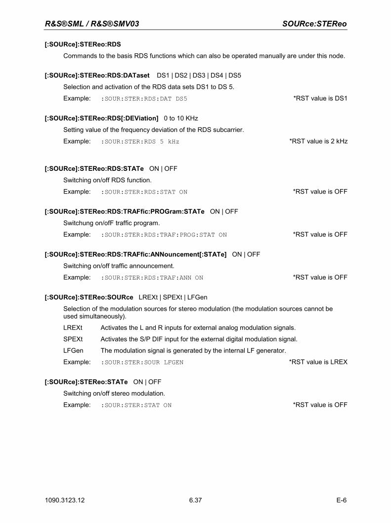
R&S®SML / R&S®SMV03 SOURce:STEReo
1090.3123.12 E-6 6.37
[:SOURce]:STEReo:RDS
Commands to the basis RDS functions which can also be operated manually are under this node.
[:SOURce]:STEReo:RDS:DATaset DS1 | DS2 | DS3 | DS4 | DS5
Selection and activation of the RDS data sets DS1 to DS 5.
Example: :SOUR:STER:RDS:DAT DS5 *RST value is DS1
[:SOURce]:STEReo:RDS[:DEViation] 0 to 10 KHz
Setting value of the frequency deviation of the RDS subcarrier.
Example: :SOUR:STER:RDS 5 kHz *RST value is 2 kHz
[:SOURce]:STEReo:RDS:STATe ON | OFF
Switching on/off RDS function.
Example: :SOUR:STER:RDS:STAT ON *RST value is OFF
[:SOURce]:STEReo:RDS:TRAFfic:PROGram:STATe ON | OFF
Switchung on/ofF traffic program.
Example: :SOUR:STER:RDS:TRAF:PROG:STAT ON *RST value is OFF
[:SOURce]:STEReo:RDS:TRAFfic:ANNouncement[:STATe] ON | OFF
Switching on/off traffic announcement.
Example: :SOUR:STER:RDS:TRAF:ANN ON *RST value is OFF
[:SOURce]:STEReo:SOURce LREXt | SPEXt | LFGen
Selection of the modulation sources for stereo modulation (the modulation sources cannot be used simultaneously).
LREXt Activates the L and R inputs for external analog modulation signals.
SPEXt Activates the S/P DIF input for the external digital modulation signal.
LFGen The modulation signal is generated by the internal LF generator.
Example: :SOUR:STER:SOUR LFGEN *RST value is LREX
[:SOURce]:STEReo:STATe ON | OFF
Switching on/off stereo modulation.
Example: :SOUR:STER:STAT ON *RST value is OFF
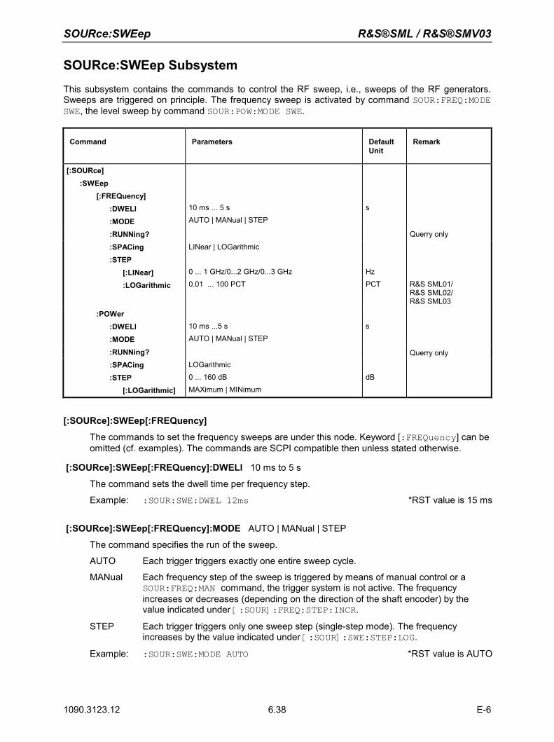
SOURce:SWEep R&S®SML / R&S®SMV03
1090.3123.12 E-6 6.38
SOURce:SWEep Subsystem
This subsystem contains the commands to control the RF sweep, i.e., sweeps of the RF generators. Sweeps are triggered on principle. The frequency sweep is activated by command SOUR:FREQ:MODE SWE, the level sweep by command SOUR:POW:MODE SWE.
Command Parameters Default Unit
Remark
[:SOURce] :SWEep [:FREQuency] :DWELl :MODE
10 ms ... 5 s AUTO | MANual | STEP
s
:RUNNing? Querry only
:SPACing :STEP [:LINear] :LOGarithmic
LINear | LOGarithmic 0 ... 1 GHz/0...2 GHz/0...3 GHz 0.01 ... 100 PCT
Hz PCT
R&S SML01/ R&S SML02/ R&S SML03
:POWer :DWELl :MODE
10 ms ...5 s AUTO | MANual | STEP
s
:RUNNing? Querry only :SPACing
:STEP [:LOGarithmic]
LOGarithmic 0 ... 160 dB MAXimum | MINimum
dB
[:SOURce]:SWEep[:FREQuency]
The commands to set the frequency sweeps are under this node. Keyword [:FREQuency] can be omitted (cf. examples). The commands are SCPI compatible then unless stated otherwise.
[:SOURce]:SWEep[:FREQuency]:DWELl 10 ms to 5 s
The command sets the dwell time per frequency step.
Example: :SOUR:SWE:DWEL 12ms *RST value is 15 ms
[:SOURce]:SWEep[:FREQuency]:MODE AUTO | MANual | STEP
The command specifies the run of the sweep.
AUTO Each trigger triggers exactly one entire sweep cycle.
MANual Each frequency step of the sweep is triggered by means of manual control or a SOUR:FREQ:MAN command, the trigger system is not active. The frequency increases or decreases (depending on the direction of the shaft encoder) by the value indicated under [:SOUR]:FREQ:STEP:INCR.
STEP Each trigger triggers only one sweep step (single-step mode). The frequency increases by the value indicated under [:SOUR]:SWE:STEP:LOG.
Example: :SOUR:SWE:MODE AUTO *RST value is AUTO
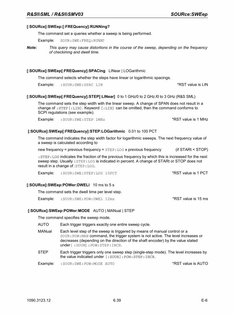
R&S®SML / R&S®SMV03 SOURce:SWEep
1090.3123.12 E-6 6.39
[:SOURce]:SWEep:[:FREQuency]:RUNNing?
The command set a queries whether a sweep is being performed.
Example: SOUR:SWE:FREQ:RUNN?
Note: This query may cause distortions in the course of the sweep, depending on the frequency of checkimng and dwell time.
[:SOURce]:SWEep[:FREQuency]:SPACing LINear | LOGarithmic
The command selects whether the steps have linear or logarithmic spacings.
Example: :SOUR:SWE:SPAC LIN *RST value is LIN
[:SOURce]:SWEep[:FREQuency]:STEP[:LINear] 0 to 1 GHz/0 to 2 GHz /0 to 3 GHz (R&S SML)
The command sets the step width with the linear sweep. A change of SPAN does not result in a change of :STEP[:LIN]. Keyword [:LIN] can be omitted, then the command conforms to SCPI regulations (see example).
Example: :SOUR:SWE:STEP 1MHz *RST value is 1 MHz
[:SOURce]:SWEep[:FREQuency]:STEP:LOGarithmic 0.01 to 100 PCT
The command indicates the step width factor for logarithmic sweeps. The next frequency value of a sweep is calculated according to
new frequency = previous frequency + STEP:LOG x previous frequency (if STARt < STOP)
:STEP:LOG indicates the fraction of the previous frequency by which this is increased for the next sweep step. Usually :STEP:LOG is indicated in percent. A change of STARt or STOP does not result in a change of :STEP:LOG.
Example: :SOUR:SWE:STEP:LOG 10PCT *RST value is 1 PCT
[:SOURce]:SWEep:POWer:DWELl 10 ms to 5 s
The command sets the dwell time per level step.
Example: :SOUR:SWE:POW:DWEL 12ms *RST value is 15 ms
[:SOURce]:SWEep:POWer:MODE AUTO | MANual | STEP
The command specifies the sweep mode.
AUTO Each trigger triggers exactly one entire sweep cycle.
MANual Each level step of the sweep is triggered by means of manual control or a SOUR:POW:MAN command, the trigger system is not active. The level increases or decreases (depending on the direction of the shaft encoder) by the value stated under [:SOUR]:POW:STEP:INCR.
STEP Each trigger triggers only one sweep step (single-step mode). The level increases by the value indicated under [:SOUR]:POW:STEP:INCR.
Example: :SOUR:SWE:POW:MODE AUTO *RST value is AUTO
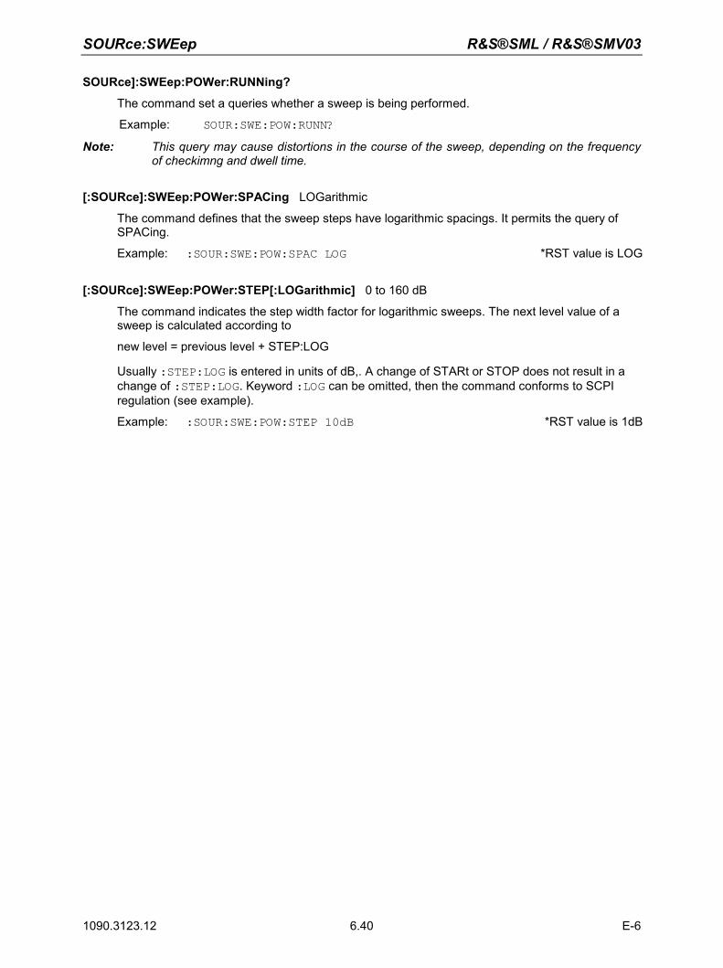
SOURce:SWEep R&S®SML / R&S®SMV03
1090.3123.12 E-6 6.40
SOURce]:SWEep:POWer:RUNNing?
The command set a queries whether a sweep is being performed.
Example: SOUR:SWE:POW:RUNN?
Note: This query may cause distortions in the course of the sweep, depending on the frequency of checkimng and dwell time.
[:SOURce]:SWEep:POWer:SPACing LOGarithmic
The command defines that the sweep steps have logarithmic spacings. It permits the query of SPACing.
Example: :SOUR:SWE:POW:SPAC LOG *RST value is LOG
[:SOURce]:SWEep:POWer:STEP[:LOGarithmic] 0 to 160 dB
The command indicates the step width factor for logarithmic sweeps. The next level value of a sweep is calculated according to
new level = previous level + STEP:LOG
Usually :STEP:LOG is entered in units of dB,. A change of STARt or STOP does not result in a change of :STEP:LOG. Keyword :LOG can be omitted, then the command conforms to SCPI regulation (see example).
Example: :SOUR:SWE:POW:STEP 10dB *RST value is 1dB
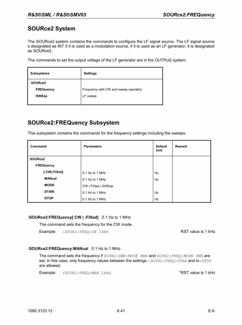
R&S®SML / R&S®SMV03 SOURce2:FREQuency
1090.3123.12 E-6 6.41
SOURce2 System
The SOURce2 system contains the commands to configure the LF signal source. The LF signal source s designated as INT if it is used as a modulation source, if it is used as an LF generator, it is designated as SOURce2. The commands to set the output voltage of the LF generator are in the OUTPut2 system.
Subsystems Settings
:SOURce2
:FREQuency
:SWEep
Frequency with CW and sweep operation
LF sweep
SOURce2:FREQuency Subsystem
This subsystem contains the commands for the frequency settings including the sweeps.
Command Parameters Default Unit
Remark
:SOURce2
:FREQuency
[:CW|:FIXed]
:MANual
:MODE
:STARt
:STOP
0.1 Hz to 1 MHz
0.1 Hz to 1 MHz
CW | FIXed | SWEep
0.1 Hz to 1 MHz
0.1 Hz to 1 MHz
Hz
Hz
Hz
Hz
:SOURce2:FREQuency[:CW | :FIXed] 0.1 Hz to 1 MHz
The command sets the frequency for the CW mode.
Example: :SOUR2:FREQ:CW 1kHz RST value is 1 kHz
:SOURce2:FREQuency:MANual 0.1 Hz to 1 MHz
The command sets the frequency if SOUR2:SWE:MODE MAN and SOUR2:FREQ:MODE SWE are set. In this case, only frequency values between the settings :SOUR2:FREQ:STAR and to:STOP are allowed.
Example: :SOUR2:FREQ:MAN 1kHz *RST value is 1 kHz
SOURce2:FREQuency R&S®SML / R&S®SMV03
1090.3123.12 E-6 6.42
:SOURce2:FREQuency:MODE CW | FIXed | SWEep
The command specifies the operating mode and hence by means of which commands the FREQuency subsystem is controlled. The following allocations are valid:
CW | FIXed CW and FIXed are synonyms. The output frequency is specified by means of SOUR2:FREQ:CW |FIX.
SWEep The generator operates in the SWEep mode. The frequency is specified by means of commands :SOUR2:FREQ:STAR; STOP; MAN.
Example: :SOUR2:FREQ:MODE CW *RST value is FIX
SOURce2:SWEep:[:FREQuency]:RUNNing?
The command set a queries whether a sweep is being performed.
Example: SOUR:SWE:FREQ:RUNN?
Note: This query may cause distortions in the course of the sweep, depending on the frequency of checkimng and dwell time.
:SOURce2:FREQuency:STARt 0.1 Hz to 1 MHz
This command defines the starting value of the frequency for the sweep.
Example: :SOUR2:FREQ:STAR 1kHz *RST value is 1 kHz
:SOURce2:FREQuency:STOP 0.1 Hz to 1 MHz
This command defines the end value of the frequency for the sweep.
Example: :SOUR2:FREQ:STOP 200kHz *RST value is 100 kHz
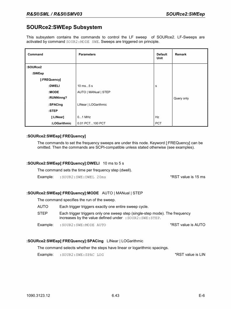
R&S®SML / R&S®SMV03 SOURce2:SWEep
1090.3123.12 E-6 6.43
SOURce2:SWEep Subsystem
This subsystem contains the commands to control the LF sweep of SOURce2. LF-Sweeps are activated by command SOUR2:MODE SWE. Sweeps are triggered on principle.
Command Parameters Default Unit
Remark
:SOURce2
:SWEep
[:FREQuency]
:DWELl
:MODE
:RUNNinng?
10 ms...5 s
AUTO | MANual | STEP
s
Query only
:SPACing
:STEP
[:LINear]
:LOGarithmic
LINear | LOGarithmic
0...1 MHz
0.01 PCT...100 PCT
Hz
PCT
:SOURce2:SWEep[:FREQuency]
The commands to set the frequency sweeps are under this node. Keyword [:FREQuency] can be omitted. Then the commands are SCPI-compatible unless stated otherwise (see examples).
:SOURce2:SWEep[:FREQuency]:DWELl 10 ms to 5 s
The command sets the time per frequency step (dwell).
Example: :SOUR2:SWE:DWEL 20ms *RST value is 15 ms
:SOURce2:SWEep[:FREQuency]:MODE AUTO | MANual | STEP
The command specifies the run of the sweep.
AUTO Each trigger triggers exactly one entire sweep cycle.
STEP Each trigger triggers only one sweep step (single-step mode). The frequency increases by the value defined under :SOUR2:SWE:STEP.
Example: :SOUR2:SWE:MODE AUTO *RST value is AUTO
:SOURce2:SWEep[:FREQuency]:SPACing LINear | LOGarithmic
The command selects whether the steps have linear or logarithmic spacings.
Example: :SOUR2:SWE:SPAC LOG *RST value is LIN
SOURce2:SWEep R&S®SML / R&S®SMV03
1090.3123.12 E-6 6.44
:SOURce2:SWEep[:FREQuency]:STEP
The commands to set the step width with linear and logarithmic sweeps are under this node. The settings of STEP:LIN and STEP:LOG are independent of each other.
:SOURce2:SWEep[:FREQuency]:STEP[:LINear] 0 to 1 MHz
The command sets the step width with the linear sweep. If STEP:LIN is changed, the value of POINts valid for SPAC:LIN also changes according to the formula defined under POINts. A change of SPAN does not cause a change of STEP:LIN. Keyword [:LIN] can be omitted, then the command conforms to SCPI regulation (see example).
Example: :SOUR2:SWE:STEP 10kHz *RST value is 1 kHz
:SOURce2:SWEep[:FREQuency]:STEP:LOGarithmic 0.01 to 100PCT
This command defines the step width factor for logarithmic sweeps. The next frequency value of a sweep is calculated as follows (if STARt < STOP) :
New frequency = previous frequency + STEP:LOG x previous frequency
STEP:LOG , therefore, indicates the fraction of the previous frequency by which that frequency is increased for the next sweep step. STEP:LOG is usually indicated in percent, with the suffix PCT having to be used explicitly. If STEP:LOG is changed, the value of POINts valid for SPACing:LOGarithmic also changes according to the formula stated under POINts. A change of STARt or STOP does not result in a change of STEP:LOGarithmic.
Example: :SOUR2:SWE:STEP:LOG 5PCT *RST value is 1 PCT
SOURce2:SWEep:[:FREQuency]:RUNNing?
The command set a queries whether a sweep is being performed.
Example: SOUR2:SWE:FREQ:RUNN?
Note: This query may cause distortions in the course of the sweep, depending on the frequency of checkimng and dwell time.
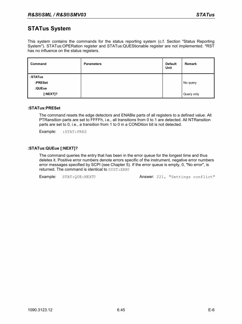
R&S®SML / R&S®SMV03 STATus
1090.3123.12 E-6 6.45
STATus System
This system contains the commands for the status reporting system (c.f. Section "Status Reporting System"). STATus:OPERation register and STATus:QUEStionable register are not implemented. *RST has no influence on the status registers.
Command Parameters Default Unit
Remark
:STATus
:PRESet
:QUEue [:NEXT]?
No query
Query only
:STATus:PRESet
The command resets the edge detectors and ENABle parts of all registers to a defined value. All PTRansition parts are set to FFFFh, i.e., all transitions from 0 to 1 are detected. All NTRansition parts are set to 0, i.e., a transition from 1 to 0 in a CONDition bit is not detected.
Example: :STAT:PRES
:STATus:QUEue [:NEXT]?
The command queries the entry that has been in the error queue for the longest time and thus deletes it. Positive error numbers denote errors specific of the instrument, negative error numbers error messages specified by SCPI (see Chapter 5). If the error queue is empty, 0, "No error", is returned. The command is identical to SYST:ERR?
Example: STAT:QUE:NEXT? Answer: 221, "Settings conflict"
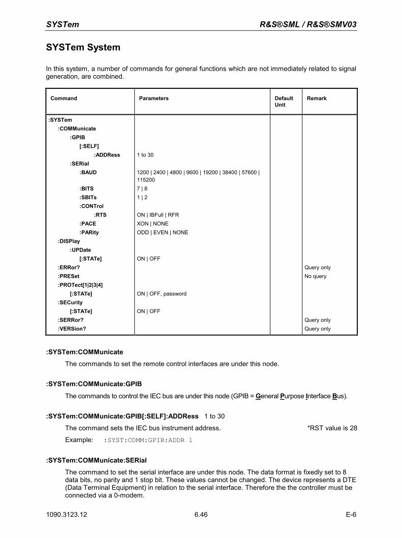
SYSTem R&S®SML / R&S®SMV03
1090.3123.12 E-6 6.46
SYSTem System
In this system, a number of commands for general functions which are not immediately related to signal generation, are combined.
Command Parameters Default Unit
Remark
:SYSTem :COMMunicate :GPIB [:SELF] :ADDRess :SERial :BAUD
:BITS :SBITs :CONTrol :RTS :PACE :PARity :DISPlay :UPDate [:STATe] :ERRor? :PRESet :PROTect[1|2|3|4] [:STATe] :SECurity [:STATe] :SERRor? :VERSion?
1 to 30 1200 | 2400 | 4800 | 9600 | 19200 | 38400 | 57600 | 115200 7 | 81 | 2
ON | IBFull | RFR XON | NONE ODD | EVEN | NONE
ON | OFF
ON | OFF, password ON | OFF
Query only No query
Query only Query only
:SYSTem:COMMunicate
The commands to set the remote control interfaces are under this node.
:SYSTem:COMMunicate:GPIB
The commands to control the IEC bus are under this node (GPIB = General Purpose Interface Bus).
:SYSTem:COMMunicate:GPIB[:SELF]:ADDRess 1 to 30
The command sets the IEC bus instrument address. *RST value is 28
Example: :SYST:COMM:GPIB:ADDR 1
:SYSTem:COMMunicate:SERial
The command to set the serial interface are under this node. The data format is fixedly set to 8 data bits, no parity and 1 stop bit. These values cannot be changed. The device represents a DTE (Data Terminal Equipment) in relation to the serial interface. Therefore the the controller must be connected via a 0-modem.
R&S®SML / R&S®SMV03 SYSTem
1090.3123.12 E-6 6.47
:SYSTem:COMMunicate:SERial:BAUD 1200| 2400| 4800| 9600| 19200| 38400| 57600| 115200
The commands sets the baud rate for both the transmit and the receive direction. *RST has no influence on this parameter.
Example: :SYST:COMM:SER:BAUD 1200 *RST value is 9600
:SYSTem:COMMunicate:SERial:BITS 7 | 8
The command sets the length of a data word.
Example: :SYST:COMM:SER:BITS *RSTvalue is 7
:SYSTem:COMMunicate:SERial:SBITs 1 | 2
The command defines whether 1 or 2 stop bits are used.
Example: :SYST:COMM:SER:SBIT *RST value is 1
:SYSTem:COMMunicate:SERial:CONTrol:RTS ON | IBFull | RFR
The commands sets the hardware handshake. *RST has no influence on this parameter. ON Interface line RTS is always active. IBFull | RFR Input Buffer Full | Ready For Receiving.
Interface line RTS remains active as long as the instrument is ready to receive data.
Example: :SYST:COMM:SER:CONT:RTS ON *RST value is RFR
:SYSTem:COMMunicate:SERial:PACE XON | NONE
The command sets the software handshake. *RST has no influnence on this parameter. XON Software handshake using the ASCII codes 11h (XON) and 13h (XOFF).
Note: This mode is not recommended for binary data and for baud rates above 9600 bauds.
NONE No software handshake.
Example: :SYST:COMM:SER:PACE NONE *RST value is NONE
:SYSTem:COMMunicate:SERial:PARity ODD | EVEN | NONE
The command defines the parity test.
Example: :SYST:COMM:SER:PAR ODD *RST value is EVEN
:SYSTem:DISPlay:UPDate[:STATe] ON | OFF
ON The header line of the display indicates frequency and level values. OFF The header line of the display remains empty. This function is only available via IEC/IEEE-bus.
Example: :SYST:DISP:UPD OFF *RST value is ON
:SYSTem:ERRor?
The command queries the entry that has been in the error queue for the longest time. Positive error numbers denote errors specific of the instrument, negative error numbers denote error messages specified by SCPI (see Chapter 9). If the error queue is empty, 0, "No error", is returned. The command is identical to STAT:QUE:NEXT?
Example: :SYST:ERR? Answer: -221, "Settings conflict"
SYSTem R&S®SML / R&S®SMV03
1090.3123.12 E-6 6.48
:SYSTem:PRESet
The command triggers an instrument reset. It has the same effect as the PRESET key of the manual control or as command *RST. This command triggers an event and hence has no *RST value. Note: By means of the "Preset RF State" item in the Level/Level menu, it is possible to
determine the switching state of the RF connector. The selected state is activated when the :SYST:PRES command is sent. If "Preset RF State“ = OFF, the command has the same effect as *RST
Example: :SYST:PRES
:SYSTem:PROTect[1|2|3|4]
The command to disable certain instrument functions is under this node. A list of the functions concerned can be found in the manual control (Chapter 4, Section "Password Input With Protected Functions"). There are four protection levels which are distinguished by means of a suffix after PROT. *RST has no effects on the disabling/enabling of the instrument functions.
:SYSTem:PROTect[1|2|3|4][:STATe] ON | OFF, Password
The command switches a protection level on or off. The passwords are 6-digit numbers. They are fixedly stored in the firmware. The password for the first level is 123456.
ON disables the functions belonging to this protection level. A password doesn't have to be entered.
OFF deactivates the disabling again if the correct password is entered. Otherwise an error -224, "Illegal parameter value" is generated and STATe remains ON.
Example: :SYST:PROT1:STAT OFF, 123456
:SYSTem:SECurity[:STATe] ON | OFF
The command switches the security state on or off.
ON The following commands cannot be executed: :DISP:ANN:ALL ON :DISP:ANN:FREQ ON :DISP:ANN:AMPL ON OFF In the transition from ON to OFF all data existing in the instrument except for the
calibrating data are deleted, especially all status registers, all instrument states and all lists.
The command is not influenced by *RST and *RCL.
Example: :SYST:SEC:STAT ON
:SYSTem:SERRor?
This command returns a list of all errors existing at the point of time of the query. The error messages are separated by commas. This list corresponds to the indication on the ERROR page with manual control (cf. Chapter 9, Section "Error Messages").
Example: :SYST:SERR? Answer: -221, "Settings conflict", 153, "Input voltage out of range"
:SYSTem:VERSion?
The command returns the SCPI version number the instrument acts in accordance with. This command is a query and thus has no *RST value.
Example: :SYST:VERS? Answer: 1994.0
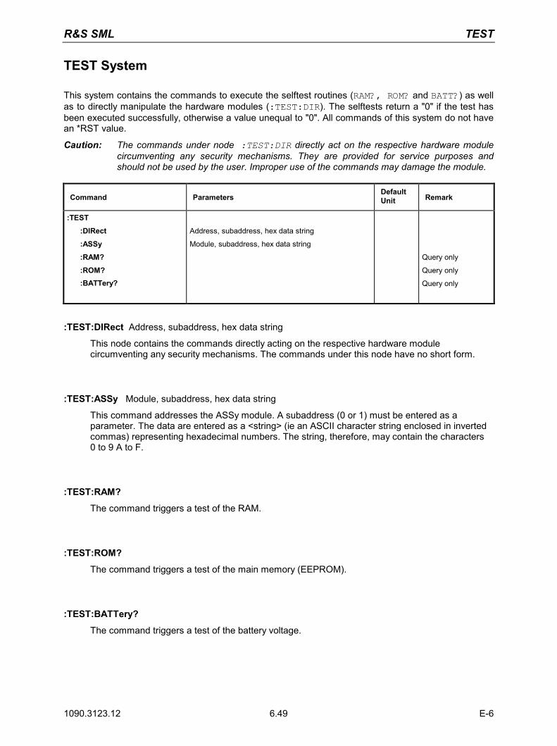
R&S SML TEST
1090.3123.12 E-6 6.49
TEST System
This system contains the commands to execute the selftest routines (RAM?, ROM? and BATT?) as well as to directly manipulate the hardware modules (:TEST:DIR). The selftests return a "0" if the test has been executed successfully, otherwise a value unequal to "0". All commands of this system do not have an *RST value.
Caution: The commands under node :TEST:DIR directly act on the respective hardware module circumventing any security mechanisms. They are provided for service purposes and should not be used by the user. Improper use of the commands may damage the module.
Command Parameters Default Unit Remark
:TEST
:DIRect
:ASSy
:RAM?
:ROM? :BATTery?
Address, subaddress, hex data string
Module, subaddress, hex data string
Query only
Query only
Query only
:TEST:DIRect Address, subaddress, hex data string
This node contains the commands directly acting on the respective hardware module circumventing any security mechanisms. The commands under this node have no short form.
:TEST:ASSy Module, subaddress, hex data string
This command addresses the ASSy module. A subaddress (0 or 1) must be entered as a parameter. The data are entered as a <string> (ie an ASCII character string enclosed in inverted commas) representing hexadecimal numbers. The string, therefore, may contain the characters 0 to 9 A to F.
:TEST:RAM?
The command triggers a test of the RAM.
:TEST:ROM?
The command triggers a test of the main memory (EEPROM).
:TEST:BATTery?
The command triggers a test of the battery voltage.
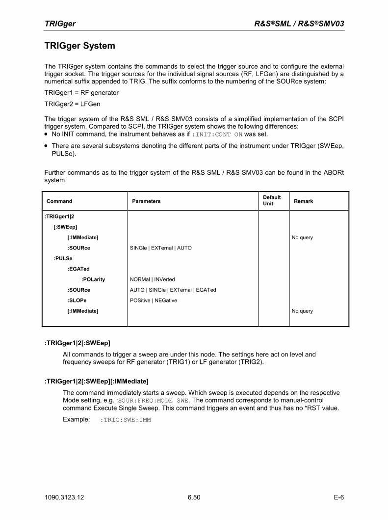
TRIGger R&S®SML / R&S®SMV03
1090.3123.12 E-6 6.50
TRIGger System
The TRIGger system contains the commands to select the trigger source and to configure the external trigger socket. The trigger sources for the individual signal sources (RF, LFGen) are distinguished by a numerical suffix appended to TRIG. The suffix conforms to the numbering of the SOURce system:
TRIGger1 = RF generator
TRIGger2 = LFGen The trigger system of the R&S SML / R&S SMV03 consists of a simplified implementation of the SCPI trigger system. Compared to SCPI, the TRIGger system shows the following differences: • No INIT command, the instrument behaves as if :INIT:CONT ON was set.
• There are several subsystems denoting the different parts of the instrument under TRIGger (SWEep, PULSe).
Further commands as to the trigger system of the R&S SML / R&S SMV03 can be found in the ABORt system.
Command Parameters Default Unit Remark
:TRIGger1|2
[:SWEep]
[:IMMediate]
:SOURce
:PULSe
:EGATed
:POLarity
:SOURce
:SLOPe
[:IMMediate]
SINGle | EXTernal | AUTO
NORMal | INVerted
AUTO | SINGle | EXTernal | EGATed
POSitive | NEGative
No query
No query
:TRIGger1|2[:SWEep]
All commands to trigger a sweep are under this node. The settings here act on level and frequency sweeps for RF generator (TRIG1) or LF generator (TRIG2).
:TRIGger1|2[:SWEep][:IMMediate]
The command immediately starts a sweep. Which sweep is executed depends on the respective Mode setting, e.g. :SOUR:FREQ:MODE SWE. The command corresponds to manual-control command Execute Single Sweep. This command triggers an event and thus has no *RST value.
Example: :TRIG:SWE:IMM
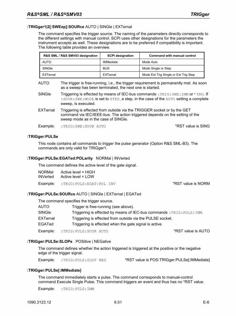
R&S®SML / R&S®SMV03 TRIGger
1090.3123.12 E-6 6.51
:TRIGger1|2[:SWEep]:SOURce AUTO | SINGle | EXTernal
The command specifies the trigger source. The naming of the parameters directly corresponds to the different settings with manual control. SCPI uses other designations for the parameters the instrument accepts as well. These designations are to be preferred if compatibility is important. The following table provides an overview.
R&S SML / R&S SMV03 designation SCPI designation Command with manual control
AUTO IMMediate Mode Auto
SINGle BUS Mode Single or Step
EXTernal EXTernal Mode Ext Trig Single or Ext Trig Step
AUTO The trigger is free-running, i.e., the trigger requirement is permanently met. As soon as a sweep has been terminated, the next one is started.
SINGle Triggering is effected by means of IEC-bus commands :TRIG:SWE:IMM or *TRG. If :SOUR:SWE:MODE is set to STEP, a step, in the case of the AUTO setting a complete sweep, is executed.
EXTernal Triggering is effected from outside via the TRIGGER socket or by the GET command via IEC/IEEE-bus. The action triggered depends on the setting of the sweep mode as in the case of SINGle.
Example: :TRIG:SWE:SOUR AUTO *RST value is SING
:TRIGger:PULSe
This node contains all commands to trigger the pulse generator (Option R&S SML-B3). The commands are only valid for TRIGger1.
:TRIGger:PULSe:EGATed:POLarity NORMal | INVerted
The command defines the active level of the gate signal.
NORMal Active level = HIGH INVerted Active level = LOW
Example: :TRIG:PULS:EGAT:POL INV *RST value is NORM
:TRIGger:PULSe:SOURce AUTO | SINGle | EXTernal | EGATed
The command specifies the trigger source. AUTO Trigger is free-running (see above). SINGle Triggering is effected by means of IEC-bus commands :TRIG:PULS:IMM.EXTernal Triggering is effected from outside via the PULSE socket. EGATed Triggering is effected when the gate signal is active.
Example: :TRIG:PULS:SOUR AUTO *RST value is AUTO
:TRIGger:PULSe:SLOPe POSitive | NEGative
The command defines whether the action triggered is triggered at the positive or the negative edge of the trigger signal.
Example: :TRIG:PULS:SLOP NEG *RST value is POS:TRIGger:PULSe[:IMMediate]
:TRIGger:PULSe[:IMMediate]
The command immediately starts a pulse. The command corresponds to manual-control command Execute Single Pulse. This command triggers an event and thus has no *RST value.
Example: :TRIG:PULS:IMM
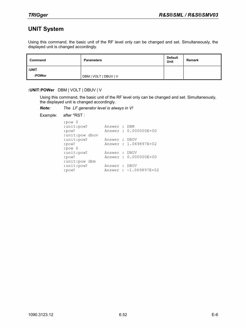
TRIGger R&S®SML / R&S®SMV03
1090.3123.12 E-6 6.52
UNIT System
Using this command, the basic unit of the RF level only can be changed and set. Simultaneously, the displayed unit is changed accordingly.
Command Parameters Default Unit Remark
:UNIT
:POWer DBM | VOLT | DBUV | V
:UNIT:POWer DBM | VOLT | DBUV | V
Using this command, the basic unit of the RF level only can be changed and set. Simultaneously, the displayed unit is changed accordingly. Note: The LF generator level is always in V!
Example: after *RST : :pow 0 :unit:pow? Answer : DBM :pow? Answer : 0.000000E+00 :unit:pow dbuv :unit:pow? Answer : DBUV :pow? Answer : 1.069897E+02 :pow 0 :unit:pow? Answer : DBUV :pow? Answer : 0.000000E+00 :unit:pow dbm :unit:pow? Answer : DBUV :pow? Answer : -1.069897E+02
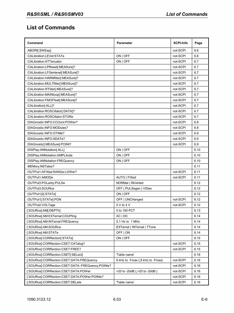
R&S®SML / R&S®SMV03 List of Commands
1090.3123.12 E-6 6.53
List of Commands
Command Parameter SCPI-Info Page
:ABORt[:SWEep] not-SCPI 6.6
:CALibration:LEVel:STATe ON | OFF not-SCPI 6.6
:CALibration:ATTenuator ON | OFF not-SCPI 6.7
:CALibration:LPReset[:MEASure]? not-SCPI 6.7
:CALibration:LFGenlevel[:MEASure]? not-SCPI 6.7
:CALibration:HARMfilter[:MEASure]? not-SCPI 6.7
:CALibration:MULTfilter[:MEASure]? not-SCPI 6.7
:CALibration:IFFilter[:MEASure]? not-SCPI 6.7
:CALibration:MAINloop[:MEASure]? not-SCPI 6.7
:CALibration:FMOFfset[:MEASure]? not-SCPI 6.7
:CALibration[:ALL]? not-SCPI 6.7
:CALibration:ROSCillator[:DATA]? not-SCPI 6.7
:CALibration:ROSCillator:STORe not-SCPI 6.7
:DIAGnostic:INFO:CCOunt:POWer? not-SCPI 6.8
:DIAGnostic:INFO:MODules? not-SCPI 6.8
:DIAGnostic:INFO:OTIMe? not-SCPI 6.9
:DIAGnostic:INFO:SDATe? not-SCPI 6.9
:DIAGnostic[:MEASure]:POINt? not-SCPI 6.9
:DISPlay:ANNotation[:ALL] ON | OFF 6.10
:DISPlay:ANNotation:AMPLitude ON | OFF 6.10
:DISPlay:ANNotation:FREQuency ON | OFF 6.10
:MEMory:NSTates? 6.11
:OUTPut1:AFIXed:RANGe:LOWer? not-SCPI 6.11
:OUTPut1:AMODe AUTO | FIXed not-SCPI 6.11
:OUTPut3:POLarity:PULSe NORMal | INVerted 6.12
:OUTPut3:SOURce OFF | PULSegen | VIDeo 6.12
:OUTPut1|2[:STATe] ON | OFF 6.12
:OUTPut1[:STATe]:PON OFF | UNCHanged not-SCPI 6.12
:OUTPut2:VOLTage 0 V to 4 V not-SCPI 6.12
[:SOURce]:AM[:DEPTh] 0 to 100 PCT 6.13
[:SOURce]:AM:EXTernal:COUPling AC | DC 6.14
[:SOURce]:AM:INTernal:FREQuency 0,1 Hz to 1 MHz 6.14
[:SOURce]:AM:SOURce EXTernal | INTernal | TTone 6.14
[:SOURce]:AM:STATe OFF | ON 6.14
[:SOURce]:CORRection[:STATe] ON | OFF 6.15
[:SOURce]:CORRection:CSET:CATalog? not-SCPI 6.15
[:SOURce]:CORRection:CSET:FREE? not-SCPI 6.15
[:SOURce]:CORRection:CSET[:SELect] 'Table name' 6.16
[:SOURce]:CORRection:CSET:DATA:FREQuency 9 kHz to Fmax ,9 kHz to Fmax not-SCPI 6.16
[:SOURce]:CORRection:CSET:DATA::FREQuency:POINts? not-SCPI 6.16
[:SOURce]:CORRection:CSET:DATA:POWer +20 to -20dB ,+20 to -20dB not-SCPI 6.16
[:SOURce]:CORRection:CSET:DATA:POWer:POINts? not-SCPI 6.16
[:SOURce]:CORRection:CSET:DELete 'Table name' not-SCPI 6.16
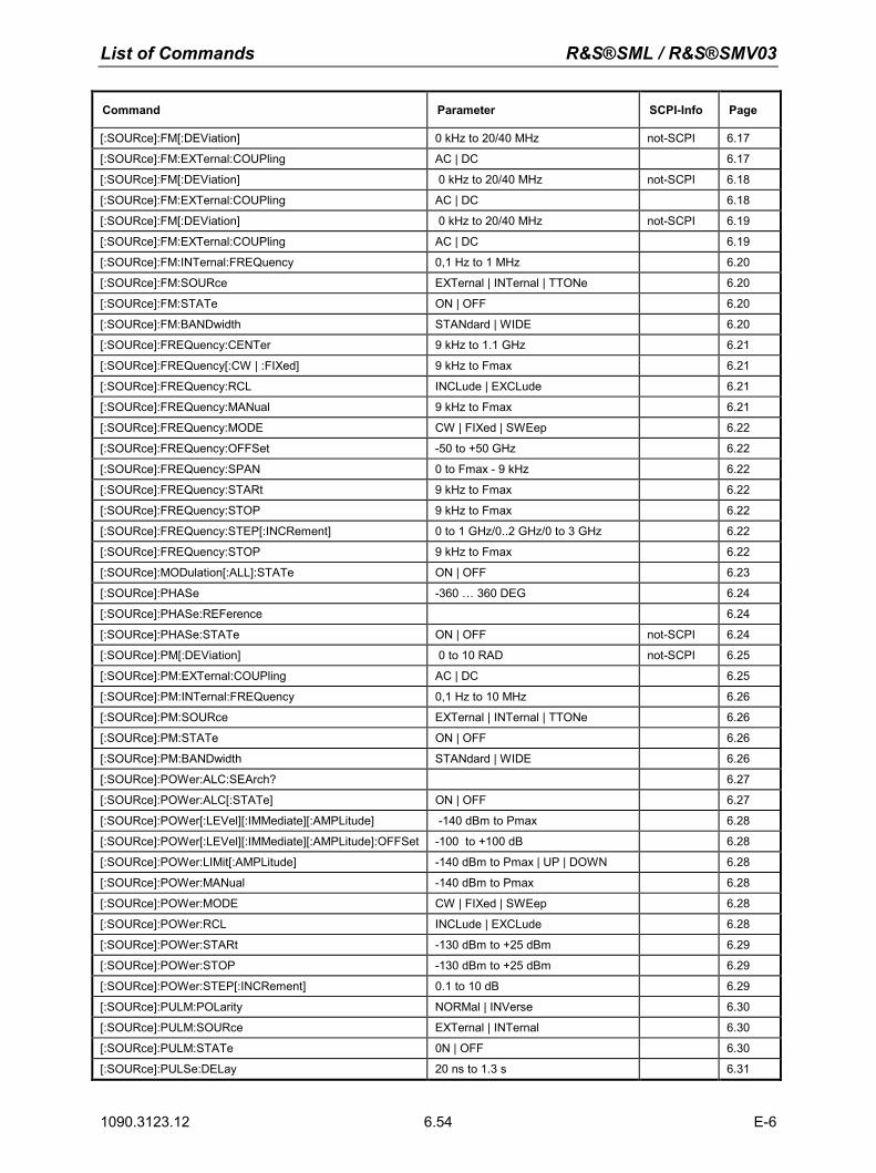
List of Commands R&S®SML / R&S®SMV03
1090.3123.12 E-6 6.54
Command Parameter SCPI-Info Page
[:SOURce]:FM[:DEViation] 0 kHz to 20/40 MHz not-SCPI 6.17
[:SOURce]:FM:EXTernal:COUPling AC | DC 6.17
[:SOURce]:FM[:DEViation] 0 kHz to 20/40 MHz not-SCPI 6.18
[:SOURce]:FM:EXTernal:COUPling AC | DC 6.18
[:SOURce]:FM[:DEViation] 0 kHz to 20/40 MHz not-SCPI 6.19
[:SOURce]:FM:EXTernal:COUPling AC | DC 6.19
[:SOURce]:FM:INTernal:FREQuency 0,1 Hz to 1 MHz 6.20
[:SOURce]:FM:SOURce EXTernal | INTernal | TTONe 6.20
[:SOURce]:FM:STATe ON | OFF 6.20
[:SOURce]:FM:BANDwidth STANdard | WIDE 6.20
[:SOURce]:FREQuency:CENTer 9 kHz to 1.1 GHz 6.21
[:SOURce]:FREQuency[:CW | :FIXed] 9 kHz to Fmax 6.21
[:SOURce]:FREQuency:RCL INCLude | EXCLude 6.21
[:SOURce]:FREQuency:MANual 9 kHz to Fmax 6.21
[:SOURce]:FREQuency:MODE CW | FIXed | SWEep 6.22
[:SOURce]:FREQuency:OFFSet -50 to +50 GHz 6.22
[:SOURce]:FREQuency:SPAN 0 to Fmax - 9 kHz 6.22
[:SOURce]:FREQuency:STARt 9 kHz to Fmax 6.22
[:SOURce]:FREQuency:STOP 9 kHz to Fmax 6.22
[:SOURce]:FREQuency:STEP[:INCRement] 0 to 1 GHz/0..2 GHz/0 to 3 GHz 6.22
[:SOURce]:FREQuency:STOP 9 kHz to Fmax 6.22
[:SOURce]:MODulation[:ALL]:STATe ON | OFF 6.23
[:SOURce]:PHASe -360 … 360 DEG 6.24
[:SOURce]:PHASe:REFerence 6.24
[:SOURce]:PHASe:STATe ON | OFF not-SCPI 6.24
[:SOURce]:PM[:DEViation] 0 to 10 RAD not-SCPI 6.25
[:SOURce]:PM:EXTernal:COUPling AC | DC 6.25
[:SOURce]:PM:INTernal:FREQuency 0,1 Hz to 10 MHz 6.26
[:SOURce]:PM:SOURce EXTernal | INTernal | TTONe 6.26
[:SOURce]:PM:STATe ON | OFF 6.26
[:SOURce]:PM:BANDwidth STANdard | WIDE 6.26
[:SOURce]:POWer:ALC:SEArch? 6.27
[:SOURce]:POWer:ALC[:STATe] ON | OFF 6.27
[:SOURce]:POWer[:LEVel][:IMMediate][:AMPLitude] -140 dBm to Pmax 6.28
[:SOURce]:POWer[:LEVel][:IMMediate][:AMPLitude]:OFFSet -100 to +100 dB 6.28
[:SOURce]:POWer:LIMit[:AMPLitude] -140 dBm to Pmax | UP | DOWN 6.28
[:SOURce]:POWer:MANual -140 dBm to Pmax 6.28
[:SOURce]:POWer:MODE CW | FIXed | SWEep 6.28
[:SOURce]:POWer:RCL INCLude | EXCLude 6.28
[:SOURce]:POWer:STARt -130 dBm to +25 dBm 6.29
[:SOURce]:POWer:STOP -130 dBm to +25 dBm 6.29
[:SOURce]:POWer:STEP[:INCRement] 0.1 to 10 dB 6.29
[:SOURce]:PULM:POLarity NORMal | INVerse 6.30
[:SOURce]:PULM:SOURce EXTernal | INTernal 6.30
[:SOURce]:PULM:STATe 0N | OFF 6.30
[:SOURce]:PULSe:DELay 20 ns to 1.3 s 6.31
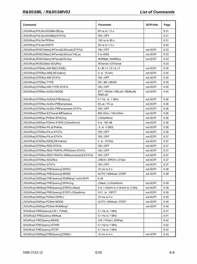
R&S®SML / R&S®SMV03 List of Commands
1090.3123.12 E-6 6.55
Command Parameter SCPI-Info Page
[:SOURce]:PULSe:DOUBle:DELay 60 ns to 1.3 s 6.31
[:SOURce]:PULSe:DOUBle[:STATe] ON | OFF 6.31
[:SOURce]:PULSe:PERiod 100 ns to 85 s 6.31
[:SOURce]:PULSe:WIDTh 20 ns to 1.3 s 6.32
[:SOURce]:ROSCillator[:INTernal]:ADJust[:STATe] ON | OFF not-SCPI 6.33
[:SOURce]:ROSCillator[:INTernal]:ADJust:VALue 0 to 4095 not-SCPI 6.33
[:SOURce]:ROSCillator[:INTernal]:RLOop NORMal | NARRow not-SCPI 6.33
[:SOURce]:ROSCillator:SOURce INTernal | EXTernal 6.33
[:SOURce]:STEReo:ARI:BK[:CODE]: A | Bl | C | D | E | F not-SCPI 6.35
[:SOURce]:STEReo:ARI[:DEViation] 0 to 10 kHz not-SCPI 6.35
[:SOURce]:STEReo:ARI:STATe ON | OFF not-SCPI 6.35
[:SOURce]:STEReo:TYPE DK | BK | BKDK not-SCPI 6.35
[:SOURce]:STEReo:ARI:TYPE:STATe ON | OFF not-SCPI 6.35
[:SOURce]:STEReo:AUDio:MODE EFT | RIGHt | RELeft | REMLeft| RNELeft
not-SCPI 6.35
[:SOURce]:STEReo:AUDio[:FREQency] 0.1 Hz to 1 MHz not-SCPI 6.36
[:SOURce]:STEReo:AUDio:PREemphasis 50 us | 75 us not-SCPI 6.36
[:SOURce]:STEReo:AUDio:PREemphasis:STATe ON | OFF not-SCPI 6.36
[:SOURce]:STEReo:EXTernal:IMPedance 600 Ohm | 100 kOhm not-SCPI 6.36
[:SOURce]:SWEep:POWer:SPACing LOGarithmic not-SCPI 6.36
[:SOURce]:SWEep:POWer:STEP[:LOGarithmic] 0 to .160 dB not-SCPI 6.36
[:SOURce]:STEReo:PILot:PHAse -5 to 5 DEG not-SCPI 6.36
[:SOURce]:STEReo:PILot:STATe ON | OFF not-SCPI 6.36
[:SOURce]:STEReo:PILot:STATe ON | OFF not-SCPI 6.37
[:SOURce]:STEReo:RDS[:DEViation] 0 to 10 KHz not-SCPI 6.37
[:SOURce]:STEReo:RDS:STATe ON | OFF not-SCPI 6.37
[:SOURce]:STEReo:RDS:TRAFfic:PROGram:STATe ON | OFF not-SCPI 6.37
[:SOURce]:STEReo:RDS:TRAFfic:ANNouncement[:STATe] ON | OFF not-SCPI 6.37
[:SOURce]:STEReo:SOURce LREXt | SPEXt | LFGen not-SCPI 6.37
[:SOURce]:STEReo:STATe ON | OFF not-SCPI 6.37
[:SOURce]:SWEep[:FREQuency]:DWELl 10 ms to 5 s not-SCPI 6.38
[:SOURce]:SWEep[:FREQuency]:MODE AUTO | MANual | STEP not-SCPI 6.38
[:SOURce]:SWEep[:FREQuency]:RUNNing? nicht-SCPI 6.39
[:SOURce]:SWEep[:FREQuency]:SPACing LINear | LOGarithmic not-SCPI 6.39
[:SOURce]:SWEep[:FREQuency]:STEP[:LINear] 0 to 1 GHz/0 to 2 GHz/0 to 3 GHz not-SCPI 6.39
[:SOURce]:SWEep[:FREQuency]:STEP:LOGarithmic 0.01 to 10PCT not-SCPI 6.39
[:SOURce]:SWEep:POWer:DWELl 10 ms to 5 s not-SCPI 6.39
[:SOURce]:SWEep:POWer:MODE AUTO | MANual | STEP not-SCPI 6.39
[:SOURce]:SWEep:POWer:RUNNing? not-SCPI 6.40
:SOURce2:FREQuency[:CW | :FIXed] 0.1 Hz to 1 MHz 6.41
:SOURce|2:FREQuency:MANual 0.1 Hz to 1 MHz 6.41
:SOURce2:FREQuency:MODE CW | FIXed | SWEep 6.42
:SOURce2:FREQuency:STARt 0.1 Hz to 1 MHz 6.42
:SOURce2:FREQuency:STOP 0.1 Hz to 1 MHz 6.42
:SOURce2:SWEep[:FREQuency]:DWELl 10 ms to 5 s not-SCPI 6.43
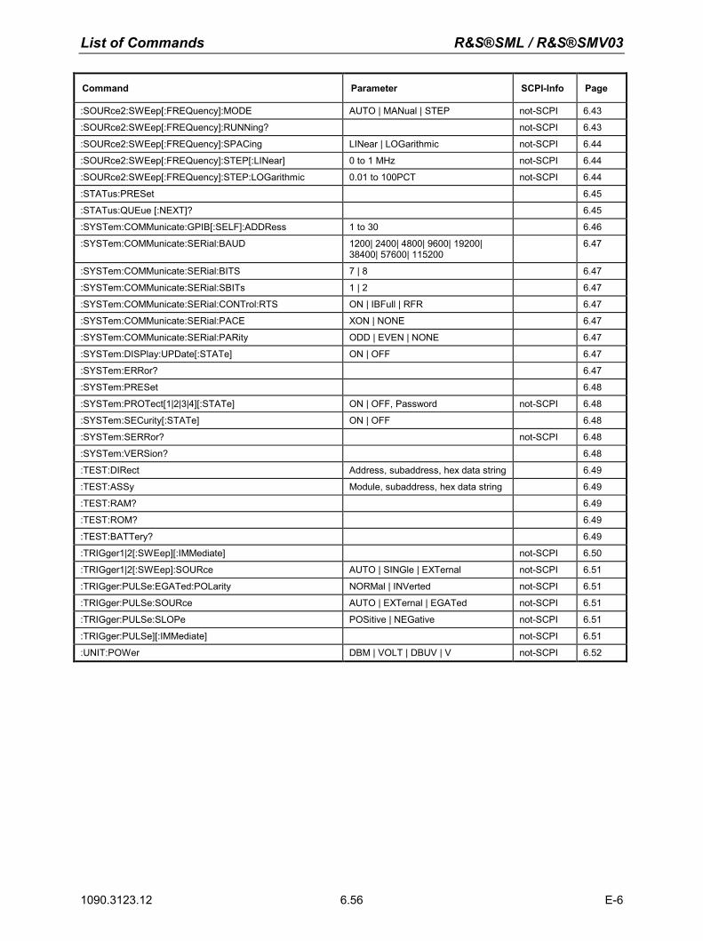
List of Commands R&S®SML / R&S®SMV03
1090.3123.12 E-6 6.56
Command Parameter SCPI-Info Page
:SOURce2:SWEep[:FREQuency]:MODE AUTO | MANual | STEP not-SCPI 6.43
:SOURce2:SWEep[:FREQuency]:RUNNing? not-SCPI 6.43
:SOURce2:SWEep[:FREQuency]:SPACing LINear | LOGarithmic not-SCPI 6.44
:SOURce2:SWEep[:FREQuency]:STEP[:LINear] 0 to 1 MHz not-SCPI 6.44
:SOURce2:SWEep[:FREQuency]:STEP:LOGarithmic 0.01 to 100PCT not-SCPI 6.44
:STATus:PRESet 6.45
:STATus:QUEue [:NEXT]? 6.45
:SYSTem:COMMunicate:GPIB[:SELF]:ADDRess 1 to 30 6.46
:SYSTem:COMMunicate:SERial:BAUD 1200| 2400| 4800| 9600| 19200| 38400| 57600| 115200
6.47
:SYSTem:COMMunicate:SERial:BITS 7 | 8 6.47
:SYSTem:COMMunicate:SERial:SBITs 1 | 2 6.47
:SYSTem:COMMunicate:SERial:CONTrol:RTS ON | IBFull | RFR 6.47
:SYSTem:COMMunicate:SERial:PACE XON | NONE 6.47
:SYSTem:COMMunicate:SERial:PARity ODD | EVEN | NONE 6.47
:SYSTem:DISPlay:UPDate[:STATe] ON | OFF 6.47
:SYSTem:ERRor? 6.47
:SYSTem:PRESet 6.48
:SYSTem:PROTect[1|2|3|4][:STATe] ON | OFF, Password not-SCPI 6.48
:SYSTem:SECurity[:STATe] ON | OFF 6.48
:SYSTem:SERRor? not-SCPI 6.48
:SYSTem:VERSion? 6.48
:TEST:DIRect Address, subaddress, hex data string 6.49
:TEST:ASSy Module, subaddress, hex data string 6.49
:TEST:RAM? 6.49
:TEST:ROM? 6.49
:TEST:BATTery? 6.49
:TRIGger1|2[:SWEep][:IMMediate] not-SCPI 6.50
:TRIGger1|2[:SWEep]:SOURce AUTO | SINGle | EXTernal not-SCPI 6.51
:TRIGger:PULSe:EGATed:POLarity NORMal | INVerted not-SCPI 6.51
:TRIGger:PULSe:SOURce AUTO | EXTernal | EGATed not-SCPI 6.51
:TRIGger:PULSe:SLOPe POSitive | NEGative not-SCPI 6.51
:TRIGger:PULSe][:IMMediate] not-SCPI 6.51
:UNIT:POWer DBM | VOLT | DBUV | V not-SCPI 6.52
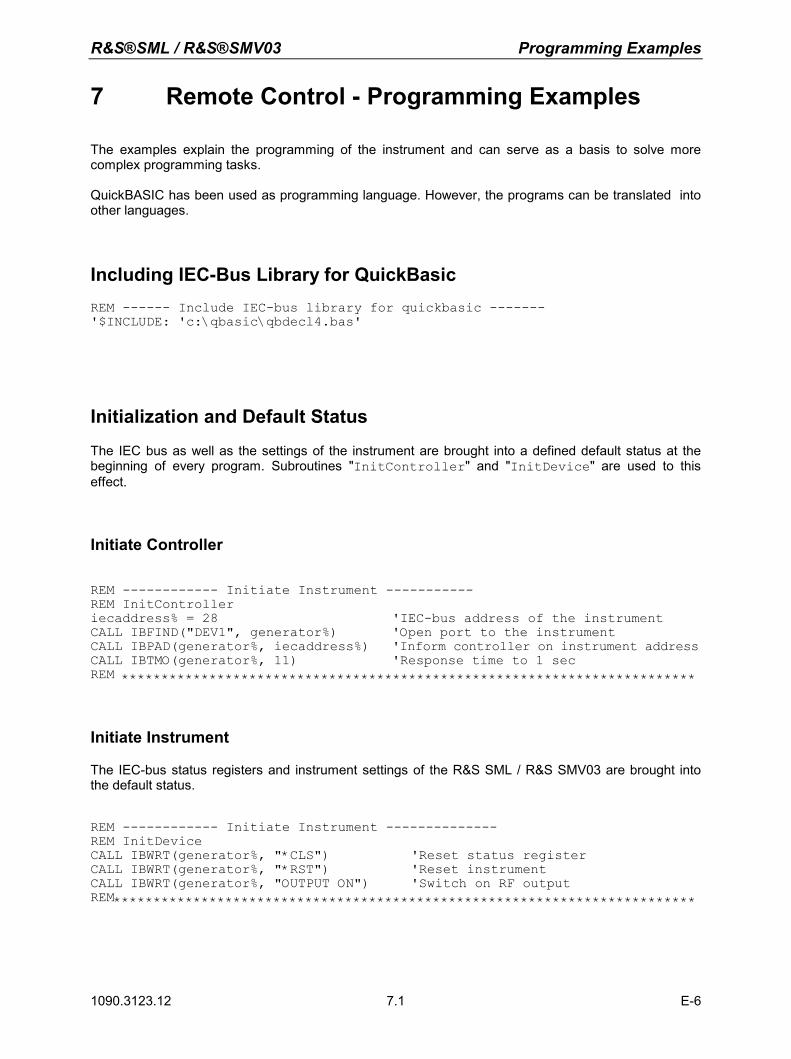
R&S®SML / R&S®SMV03 Programming Examples
1090.3123.12 E-6 7.1
7 Remote Control - Programming Examples
The examples explain the programming of the instrument and can serve as a basis to solve more complex programming tasks. QuickBASIC has been used as programming language. However, the programs can be translated into other languages.
Including IEC-Bus Library for QuickBasic REM ------ Include IEC-bus library for quickbasic ------- '$INCLUDE: 'c:\qbasic\qbdecl4.bas'
Initialization and Default Status
The IEC bus as well as the settings of the instrument are brought into a defined default status at the beginning of every program. Subroutines "InitController" and "InitDevice" are used to this effect.
Initiate Controller
REM ------------ Initiate Instrument ----------- REM InitController iecaddress% = 28 'IEC-bus address of the instrument CALL IBFIND("DEV1", generator%) 'Open port to the instrument CALL IBPAD(generator%, iecaddress%) 'Inform controller on instrument address CALL IBTMO(generator%, 11) 'Response time to 1 sec REM ************************************************************************
Initiate Instrument
The IEC-bus status registers and instrument settings of the R&S SML / R&S SMV03 are brought into the default status.
REM ------------ Initiate Instrument -------------- REM InitDevice CALL IBWRT(generator%, "*CLS") 'Reset status register CALL IBWRT(generator%, "*RST") 'Reset instrument CALL IBWRT(generator%, "OUTPUT ON") 'Switch on RF output REM*************************************************************************
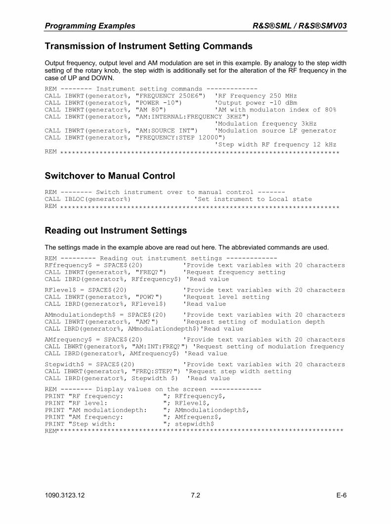
Programming Examples R&S®SML / R&S®SMV03
1090.3123.12 E-6 7.2
Transmission of Instrument Setting Commands
Output frequency, output level and AM modulation are set in this example. By analogy to the step width setting of the rotary knob, the step width is additionally set for the alteration of the RF frequency in the case of UP and DOWN. REM -------- Instrument setting commands ------------- CALL IBWRT(generator%, "FREQUENCY 250E6") 'RF Frequency 250 MHz CALL IBWRT(generator%, "POWER -10") 'Output power -10 dBm CALL IBWRT(generator%, "AM 80") 'AM with modulaton index of 80% CALL IBWRT(generator%, "AM:INTERNAL:FREQUENCY 3KHZ") 'Modulation frequency 3kHz CALL IBWRT(generator%, "AM:SOURCE INT") 'Modulation source LF generator CALL IBWRT(generator%, "FREQUENCY:STEP 12000") 'Step width RF frequency 12 kHz REM ***********************************************************************
Switchover to Manual Control REM -------- Switch instrument over to manual control ------- CALL IBLOC(generator%) 'Set instrument to Local state REM ***********************************************************************
Reading out Instrument Settings
The settings made in the example above are read out here. The abbreviated commands are used. REM --------- Reading out instrument settings ------------- RFfrequency$ = SPACE$(20) 'Provide text variables with 20 characters CALL IBWRT(generator%, "FREQ?") 'Request frequency setting CALL IBRD(generator%, RFfrequency$) 'Read value RFlevel$ = SPACE$(20) 'Provide text variables with 20 characters CALL IBWRT(generator%, "POW?") 'Request level setting CALL IBRD(generator%, RFlevel$) 'Read value AMmodulationdepth$ = SPACE$(20) 'Provide text variables with 20 characters CALL IBWRT(generator%, "AM?") 'Request setting of modulation depth CALL IBRD(generator%, AMmodulationdepth$)'Read value AMfrequency$ = SPACE$(20) 'Provide text variables with 20 characters CALL IBWRT(generator%, "AM:INT:FREQ?") 'Request setting of modulation frequency CALL IBRD(generator%, AMfrequency$) 'Read value Stepwidth$ = SPACE$(20) 'Provide text variables with 20 characters CALL IBWRT(generator%, "FREQ:STEP?") 'Request step width setting CALL IBRD(generator%, Stepwidth $) 'Read value REM -------- Display values on the screen ------------- PRINT "RF frequency: "; RFfrequency$, PRINT "RF level: "; RFlevel$, PRINT "AM modulationdepth: "; AMmodulationdepth$, PRINT "AM frequency: "; AMfrequenz$, PRINT "Step width: "; stepwidth$ REM*************************************************************************
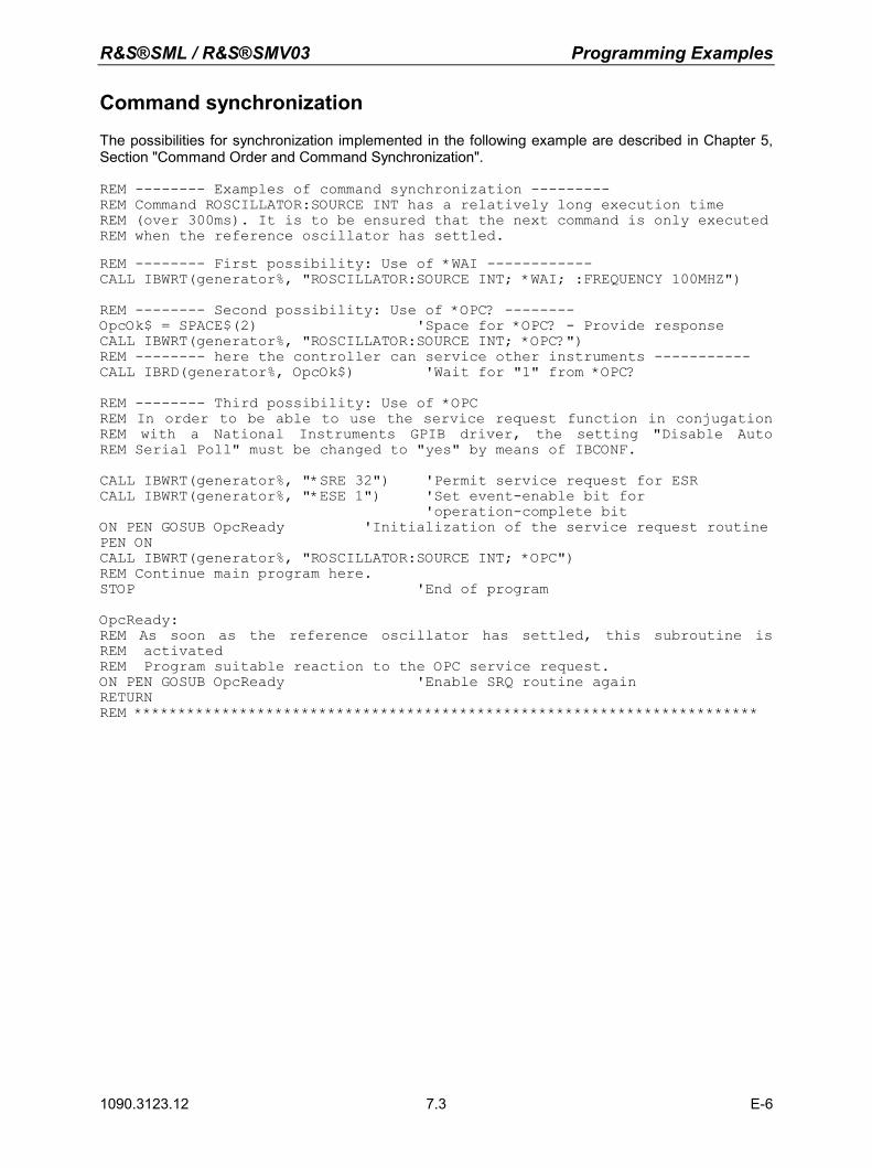
R&S®SML / R&S®SMV03 Programming Examples
1090.3123.12 E-6 7.3
Command synchronization
The possibilities for synchronization implemented in the following example are described in Chapter 5, Section "Command Order and Command Synchronization". REM -------- Examples of command synchronization --------- REM Command ROSCILLATOR:SOURCE INT has a relatively long execution time REM (over 300ms). It is to be ensured that the next command is only executed REM when the reference oscillator has settled. REM -------- First possibility: Use of *WAI ------------ CALL IBWRT(generator%, "ROSCILLATOR:SOURCE INT; *WAI; :FREQUENCY 100MHZ") REM -------- Second possibility: Use of *OPC? -------- OpcOk$ = SPACE$(2) 'Space for *OPC? - Provide response CALL IBWRT(generator%, "ROSCILLATOR:SOURCE INT; *OPC?") REM -------- here the controller can service other instruments ----------- CALL IBRD(generator%, OpcOk$) 'Wait for "1" from *OPC? REM -------- Third possibility: Use of *OPC REM In order to be able to use the service request function in conjugation REM with a National Instruments GPIB driver, the setting "Disable Auto REM Serial Poll" must be changed to "yes" by means of IBCONF. CALL IBWRT(generator%, "*SRE 32") 'Permit service request for ESR CALL IBWRT(generator%, "*ESE 1") 'Set event-enable bit for 'operation-complete bit ON PEN GOSUB OpcReady 'Initialization of the service request routine PEN ON CALL IBWRT(generator%, "ROSCILLATOR:SOURCE INT; *OPC") REM Continue main program here. STOP 'End of program OpcReady: REM As soon as the reference oscillator has settled, this subroutine is REM activated REM Program suitable reaction to the OPC service request. ON PEN GOSUB OpcReady 'Enable SRQ routine again RETURN REM ***********************************************************************
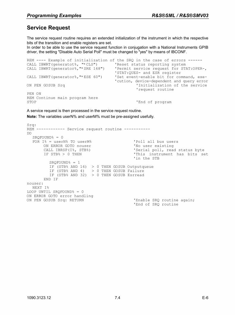
Programming Examples R&S®SML / R&S®SMV03
1090.3123.12 E-6 7.4
Service Request
The service request routine requires an extended initialization of the instrument in which the respective bits of the transition and enable registers are set. In order to be able to use the service request function in conjugation with a National Instruments GPIB driver, the setting "Disable Auto Serial Poll" must be changed to "yes" by means of IBCONF. REM ---- Example of initialization of the SRQ in the case of errors ------ CALL IBWRT(generatot%, "*CLS") 'Reset status reporting system CALL IBWRT(generator%,"*SRE 168") 'Permit service request for STAT:OPER-, 'STAT:QUES- and ESR register CALL IBWRT(generator%,"*ESE 60") 'Set event-enable bit for command, exe- 'cution, device-dependent and query error ON PEN GOSUB Srq 'Initialization of the service 'request routine PEN ON REM Continue main program here STOP 'End of program A service request is then processed in the service request routine. Note: The variables userN% and userM% must be pre-assigned usefully. Srq: REM ------------ Service request routine ----------- DO SRQFOUND% = 0 FOR I% = userN% TO userM% 'Poll all bus users ON ERROR GOTO nouser 'No user existing CALL IBRSP(I%, STB%) 'Serial poll, read status byte IF STB% > 0 THEN 'This instrument has bits set 'in the STB SRQFOUND% = 1 IF (STB% AND 16) > 0 THEN GOSUB Outputqueue IF (STB% AND 4) > 0 THEN GOSUB Failure IF (STB% AND 32) > 0 THEN GOSUB Esrread END IF nouser: NEXT I% LOOP UNTIL SRQFOUND% = 0 ON ERROR GOTO error handling ON PEN GOSUB Srq: RETURN 'Enable SRQ routine again; 'End of SRQ routine
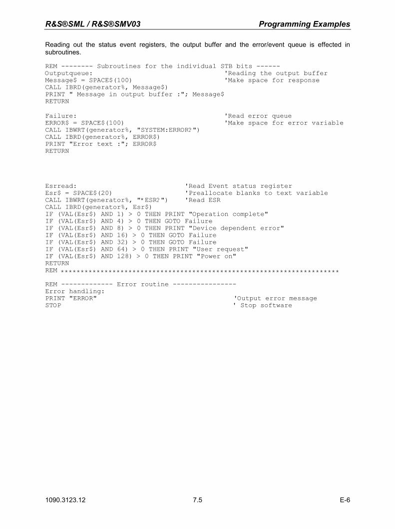
R&S®SML / R&S®SMV03 Programming Examples
1090.3123.12 E-6 7.5
Reading out the status event registers, the output buffer and the error/event queue is effected in subroutines. REM -------- Subroutines for the individual STB bits ------ Outputqueue: 'Reading the output buffer Message$ = SPACE$(100) 'Make space for response CALL IBRD(generator%, Message$) PRINT " Message in output buffer :"; Message$ RETURN Failure: 'Read error queue ERROR$ = SPACE$(100) 'Make space for error variable CALL IBWRT(generator%, "SYSTEM:ERROR?") CALL IBRD(generator%, ERROR$) PRINT "Error text :"; ERROR$ RETURN
Esrread: 'Read Event status register Esr$ = SPACE$(20) 'Preallocate blanks to text variable CALL IBWRT(generator%, "*ESR?") 'Read ESR CALL IBRD(generator%, Esr$) IF (VAL(Esr$) AND 1) > 0 THEN PRINT "Operation complete" IF (VAL(Esr$) AND 4) > 0 THEN GOTO Failure IF (VAL(Esr$) AND 8) > 0 THEN PRINT "Device dependent error" IF (VAL(Esr$) AND 16) > 0 THEN GOTO Failure IF (VAL(Esr$) AND 32) > 0 THEN GOTO Failure IF (VAL(Esr$) AND 64) > 0 THEN PRINT "User request" IF (VAL(Esr$) AND 128) > 0 THEN PRINT "Power on" RETURN REM **********************************************************************
REM ------------- Error routine ---------------- Error handling: PRINT "ERROR" 'Output error message STOP ' Stop software

R&S®SML / R&S®SMV03 Maintenance
1090.3123.12 E-6 8.1
8 Maintenance
The present chapter describes the measures that are necessary for maintaining, storing and packing the instrument. The instrument does not need a periodic maintenance. What is necessary is essentially the cleaning of the outside of the instrument. However, it is recommended to check the rated data from time to time.
Storing and Packing
The instrument can be stored at a temperature of –40° C to +70° C. When stored for an extended period of time, the instrument should be protected against dust.
The original packing should be used, particularly the protective covers at the front and rear, when the instrument is to be transported or dispatched. If the original packing is no longer available, use a sturdy cardboard box of suitable size and carefully wrap the instrument to protect it against mechanical damage.
Exchanging the Lithium Battery
A lithium battery with a service life of approx. 5 years serves to supply the RAM with power. When the battery is discharged, the data stored will be lost. Exchanging the battery is described in the Service Manual.

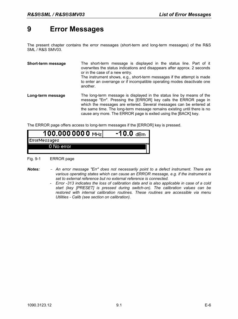
R&S®SML / R&S®SMV03 List of Error Messages
1090.3123.12 E-6 9.1
9 Error Messages
The present chapter contains the error messages (short-term and long-term messages) of the R&S SML / R&S SMV03.
Short-term message The short-term message is displayed in the status line. Part of it overwrites the status indications and disappears after approx. 2 seconds or in the case of a new entry. The instrument shows, e.g., short-term messages if the attempt is made to enter an overrange or if incompatible operating modes deactivate one another.
Long-term message The long-term message is displayed in the status line by means of the message "Err". Pressing the [ERROR] key calls the ERROR page in which the messages are entered. Several messages can be entered at the same time. The long-term message remains existing until there is no cause any more. The ERROR page is exited using the [BACK] key.
The ERROR page offers access to long-term messages if the [ERROR] key is pressed.
Fig. 9-1 ERROR page Notes: - An error message "Err" does not necessarily point to a defect instrument. There are
various operating states which can cause an ERROR message, e.g. if the instrument is set to external reference but no external reference is connected.
- Error -313 indicates the loss of calibration data and is also applicable in case of a cold start (key [PRESET] is pressed during switch-on). The calibration values can be restored with internal calibration routines. These routines are accessible via menu Utilities - Calib (see section on calibration).
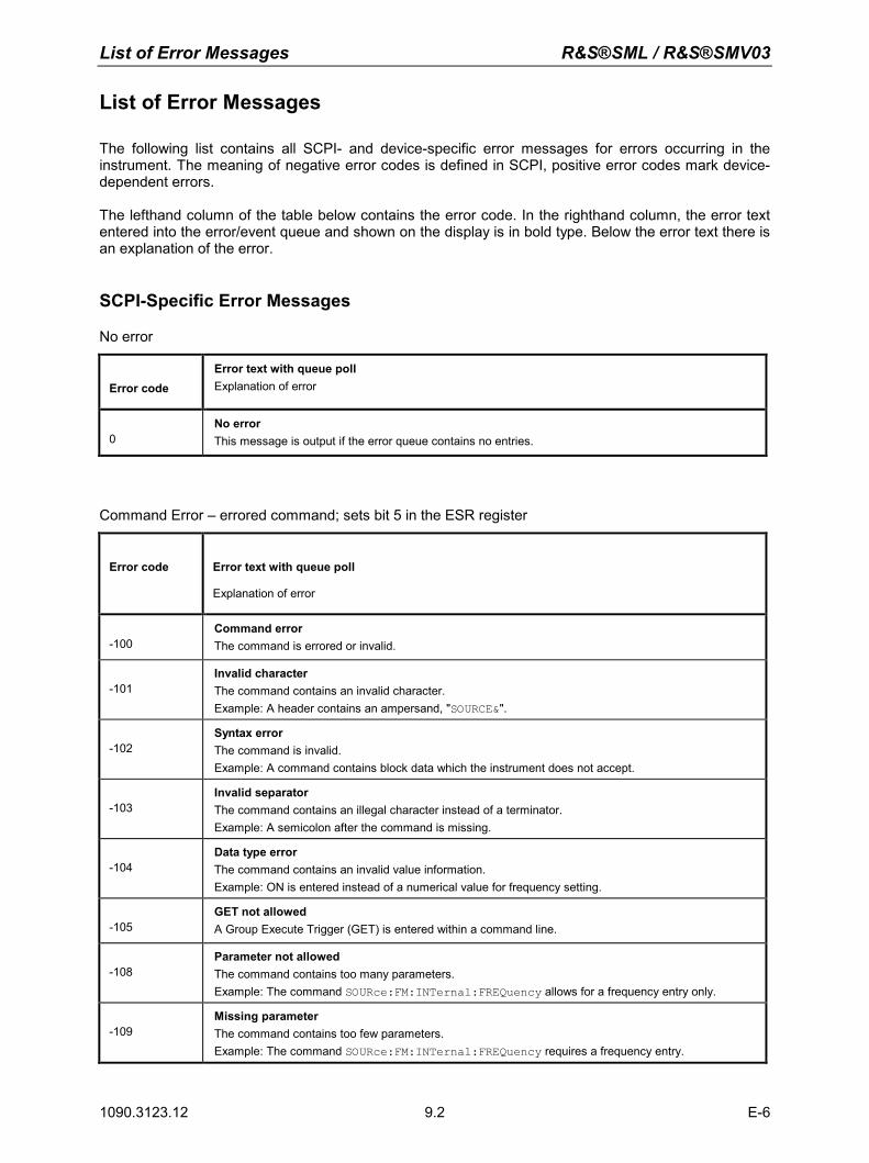
List of Error Messages R&S®SML / R&S®SMV03
1090.3123.12 E-6 9.2
List of Error Messages
The following list contains all SCPI- and device-specific error messages for errors occurring in the instrument. The meaning of negative error codes is defined in SCPI, positive error codes mark device-dependent errors. The lefthand column of the table below contains the error code. In the righthand column, the error text entered into the error/event queue and shown on the display is in bold type. Below the error text there is an explanation of the error.
SCPI-Specific Error Messages
No error
Error code Error text with queue poll Explanation of error
0No error This message is output if the error queue contains no entries.
Command Error – errored command; sets bit 5 in the ESR register
Error code Error text with queue poll
Explanation of error
-100 Command error The command is errored or invalid.
-101 Invalid character The command contains an invalid character. Example: A header contains an ampersand, "SOURCE&".
-102 Syntax error The command is invalid. Example: A command contains block data which the instrument does not accept.
-103 Invalid separator The command contains an illegal character instead of a terminator. Example: A semicolon after the command is missing.
-104 Data type error The command contains an invalid value information. Example: ON is entered instead of a numerical value for frequency setting.
-105 GET not allowed A Group Execute Trigger (GET) is entered within a command line.
-108 Parameter not allowed The command contains too many parameters. Example: The command SOURce:FM:INTernal:FREQuency allows for a frequency entry only.
-109 Missing parameter The command contains too few parameters. Example: The command SOURce:FM:INTernal:FREQuency requires a frequency entry.
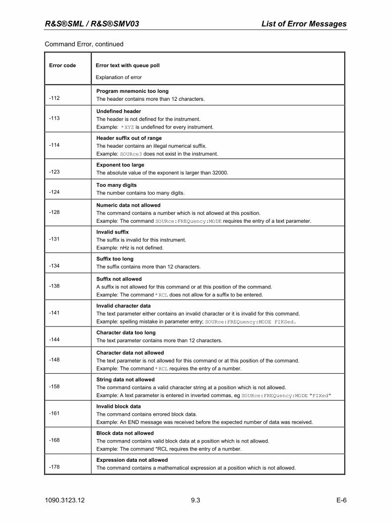
R&S®SML / R&S®SMV03 List of Error Messages
1090.3123.12 E-6 9.3
Command Error, continued
Error code Error text with queue poll
Explanation of error
-112 Program mnemonic too long The header contains more than 12 characters.
-113 Undefined header The header is not defined for the instrument. Example: *XYZ is undefined for every instrument.
-114 Header suffix out of range The header contains an illegal numerical suffix. Example: SOURce3 does not exist in the instrument.
-123 Exponent too large The absolute value of the exponent is larger than 32000.
-124 Too many digits The number contains too many digits.
-128 Numeric data not allowed The command contains a number which is not allowed at this position. Example: The command SOURce:FREQuency:MODE requires the entry of a text parameter.
-131 Invalid suffix The suffix is invalid for this instrument. Example: nHz is not defined.
-134 Suffix too long The suffix contains more than 12 characters.
-138 Suffix not allowed A suffix is not allowed for this command or at this position of the command. Example: The command *RCL does not allow for a suffix to be entered.
-141 Invalid character data The text parameter either contains an invalid character or it is invalid for this command. Example: spelling mistake in parameter entry; SOURce:FREQuency:MODE FIKSed.
-144 Character data too long The text parameter contains more than 12 characters.
-148 Character data not allowed The text parameter is not allowed for this command or at this position of the command. Example: The command *RCL requires the entry of a number.
-158 String data not allowed The command contains a valid character string at a position which is not allowed. Example: A text parameter is entered in inverted commas, eg SOURce:FREQuency:MODE "FIXed"
-161 Invalid block data The command contains errored block data. Example: An END message was received before the expected number of data was received.
-168 Block data not allowed The command contains valid block data at a position which is not allowed. Example: The command *RCL requires the entry of a number.
-178 Expression data not allowed The command contains a mathematical expression at a position which is not allowed.
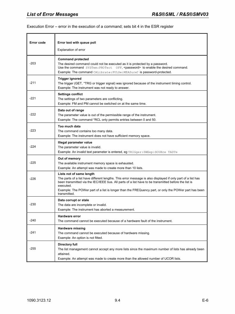
List of Error Messages R&S®SML / R&S®SMV03
1090.3123.12 E-6 9.4
Execution Error – error in the execution of a command; sets bit 4 in the ESR register
Error code Error text with queue poll
Explanation of error
-203 Command protected The desired command could not be executed as it is protected by a password. Use the command SYSTem:PROTect OFF, <password> to enable the desired command. Example: The command CALibrate:PULSe:MEASure? is password-protected.
-211 Trigger ignored The trigger (GET, *TRG or trigger signal) was ignored because of the instrument timing control. Example: The instrument was not ready to answer.
-221 Settings conflict The settings of two parameters are conflicting. Example: FM and PM cannot be switched on at the same time.
-222 Data out of range The parameter value is out of the permissible range of the instrument. Example: The command *RCL only permits entries between 0 and 50.
-223 Too much data The command contains too many data. Example: The instrument does not have sufficient memory space.
-224 Illegal parameter value The parameter value is invalid. Example: An invalid text parameter is entered, eg TRIGger:SWEep:SOURce TASTe
-225 Out of memory The available instrument memory space is exhausted. Example: An attempt was made to create more than 10 lists.
-226 Lists not of same length The parts of a list have different lengths. This error message is also displayed if only part of a list has been transmitted via the IEC/IEEE bus. All parts of a list have to be transmitted before the list is executed. Example: The POWer part of a list is longer than the FREQuency part, or only the POWer part has been transmitted.
-230 Data corrupt or stale The data are incomplete or invalid. Example: The instrument has aborted a measurement.
-240 Hardware error The command cannot be executed because of a hardware fault of the instrument.
-241 Hardware missing The command cannot be executed because of hardware missing. Example: An option is not fitted.
-255 Directory full The list management cannot accept any more lists since the maximum number of lists has already been attained. Example: An attempt was made to create more than the allowed number of UCOR lists.
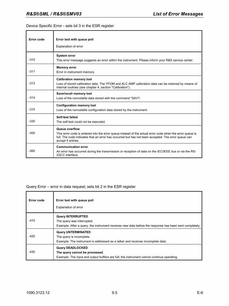
R&S®SML / R&S®SMV03 List of Error Messages
1090.3123.12 E-6 9.5
Device Specific Error - sets bit 3 in the ESR register
Error code Error text with queue poll
Explanation of error
-310 System error This error message suggests an error within the instrument. Please inform your R&S service center.
-311 Memory error Error in instrument memory.
-313 Calibration memory lost Loss of stored calibration data. The YFOM and ALC AMP calibration data can be restored by means of internal routines (see chapter 4, section "Calibration").
-314 Save/recall memory lost Loss of the nonvolatile data stored with the command *SAV?.
-315 Configuration memory lost Loss of the nonvolatile configuration data stored by the instrument.
-330 Self-test failed The self-test could not be executed.
-350 Queue overflow This error code is entered into the error queue instead of the actual error code when the error queue is full. The code indicates that an error has occurred but has not been accepted. The error queue can accept 5 entries.
-360 Communication error An error has occurred during the transmission or reception of data on the IEC/IEEE bus or via the RS-232-C interface.
Query Error – error in data request; sets bit 2 in the ESR register
Error code Error text with queue poll
Explanation of error
-410 Query INTERRUPTED The query was interrupted. Example: After a query, the instrument receives new data before the response has been sent completely.
-420 Query UNTERMINATED The query is incomplete. Example: The instrument is addressed as a talker and receives incomplete data.
-430 Query DEADLOCKED The query cannot be processed.Example: The input and output buffers are full; the instrument cannot continue operating.
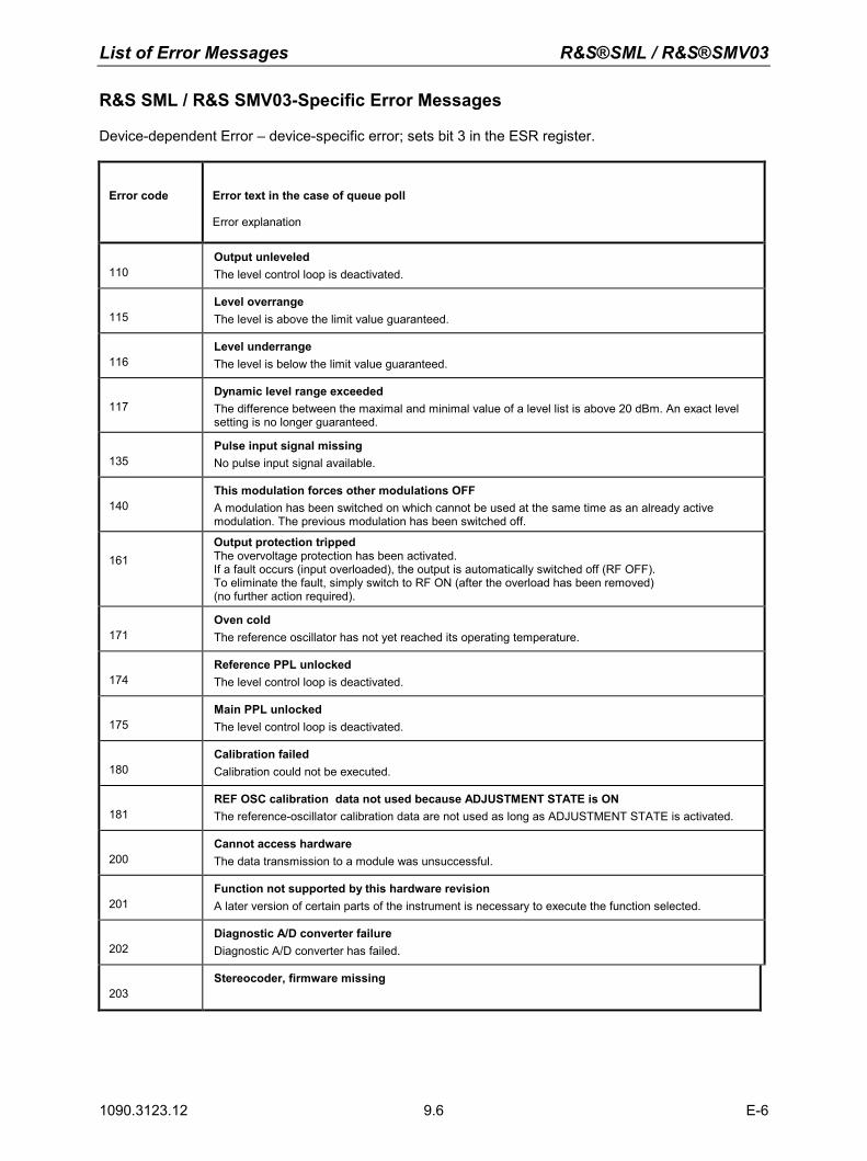
List of Error Messages R&S®SML / R&S®SMV03
1090.3123.12 E-6 9.6
R&S SML / R&S SMV03-Specific Error Messages
Device-dependent Error – device-specific error; sets bit 3 in the ESR register.
Error code Error text in the case of queue poll
Error explanation
110 Output unleveled The level control loop is deactivated.
115 Level overrange The level is above the limit value guaranteed.
116 Level underrange The level is below the limit value guaranteed.
117 Dynamic level range exceeded The difference between the maximal and minimal value of a level list is above 20 dBm. An exact level setting is no longer guaranteed.
135 Pulse input signal missing No pulse input signal available.
140 This modulation forces other modulations OFF A modulation has been switched on which cannot be used at the same time as an already active modulation. The previous modulation has been switched off.
161 Output protection tripped The overvoltage protection has been activated. If a fault occurs (input overloaded), the output is automatically switched off (RF OFF). To eliminate the fault, simply switch to RF ON (after the overload has been removed) (no further action required).
171 Oven cold The reference oscillator has not yet reached its operating temperature.
174 Reference PPL unlocked The level control loop is deactivated.
175 Main PPL unlocked The level control loop is deactivated.
180 Calibration failed Calibration could not be executed.
181 REF OSC calibration data not used because ADJUSTMENT STATE is ON The reference-oscillator calibration data are not used as long as ADJUSTMENT STATE is activated.
200 Cannot access hardware The data transmission to a module was unsuccessful.
201 Function not supported by this hardware revision A later version of certain parts of the instrument is necessary to execute the function selected.
202 Diagnostic A/D converter failure Diagnostic A/D converter has failed.
203 Stereocoder, firmware missing
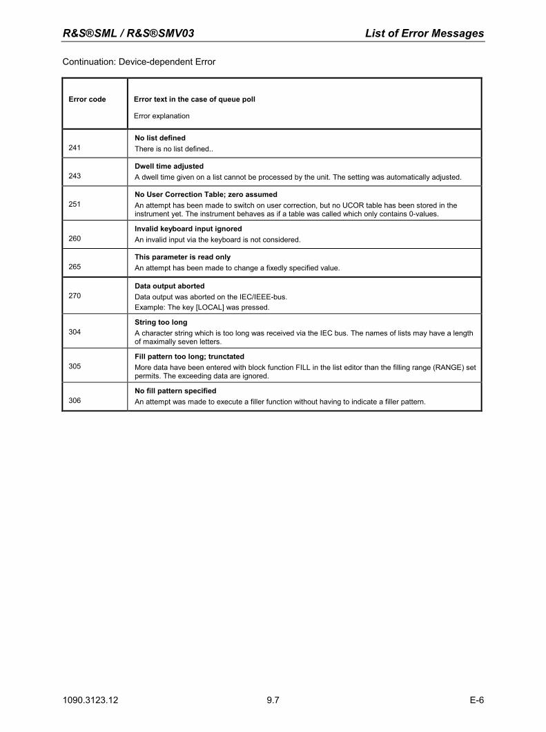
R&S®SML / R&S®SMV03 List of Error Messages
1090.3123.12 E-6 9.7
Continuation: Device-dependent Error
Error code Error text in the case of queue poll
Error explanation
241 No list defined There is no list defined..
243 Dwell time adjusted A dwell time given on a list cannot be processed by the unit. The setting was automatically adjusted.
251 No User Correction Table; zero assumed An attempt has been made to switch on user correction, but no UCOR table has been stored in the instrument yet. The instrument behaves as if a table was called which only contains 0-values.
260 Invalid keyboard input ignored An invalid input via the keyboard is not considered.
265 This parameter is read only An attempt has been made to change a fixedly specified value.
270 Data output aborted Data output was aborted on the IEC/IEEE-bus. Example: The key [LOCAL] was pressed.
304 String too long A character string which is too long was received via the IEC bus. The names of lists may have a length of maximally seven letters.
305 Fill pattern too long; trunctated More data have been entered with block function FILL in the list editor than the filling range (RANGE) set permits. The exceeding data are ignored.
306 No fill pattern specified An attempt was made to execute a filler function without having to indicate a filler pattern.
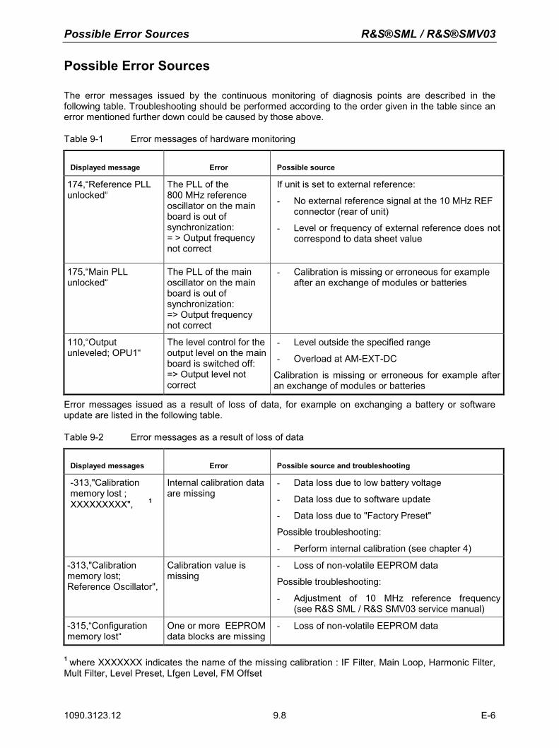
Possible Error Sources R&S®SML / R&S®SMV03
1090.3123.12 E-6 9.8
Possible Error Sources
The error messages issued by the continuous monitoring of diagnosis points are described in the following table. Troubleshooting should be performed according to the order given in the table since an error mentioned further down could be caused by those above.
Table 9-1 Error messages of hardware monitoring
Displayed message Error Possible source
174,“Reference PLL unlocked“
The PLL of the 800 MHz reference oscillator on the main board is out of synchronization: = > Output frequency not correct
If unit is set to external reference:
- No external reference signal at the 10 MHz REF connector (rear of unit)
- Level or frequency of external reference does not correspond to data sheet value
175,“Main PLL unlocked“
The PLL of the main oscillator on the main board is out of synchronization: => Output frequency not correct
- Calibration is missing or erroneous for example after an exchange of modules or batteries
110,“Output unleveled; OPU1“
The level control for the output level on the main board is switched off: => Output level not correct
- Level outside the specified range
- Overload at AM-EXT-DC
Calibration is missing or erroneous for example after an exchange of modules or batteries
Error messages issued as a result of loss of data, for example on exchanging a battery or software update are listed in the following table.
Table 9-2 Error messages as a result of loss of data
Displayed messages Error Possible source and troubleshooting
-313,"Calibration memory lost ; XXXXXXXXX", 1
Internal calibration data are missing
- Data loss due to low battery voltage
- Data loss due to software update
- Data loss due to "Factory Preset"
Possible troubleshooting:
- Perform internal calibration (see chapter 4)
-313,"Calibration memory lost; Reference Oscillator",
Calibration value is missing
- Loss of non-volatile EEPROM data
Possible troubleshooting:
- Adjustment of 10 MHz reference frequency(see R&S SML / R&S SMV03 service manual)
-315,“Configuration memory lost“
One or more EEPROM data blocks are missing
- Loss of non-volatile EEPROM data
1 where XXXXXXX indicates the name of the missing calibration : IF Filter, Main Loop, Harmonic Filter, Mult Filter, Level Preset, Lfgen Level, FM Offset
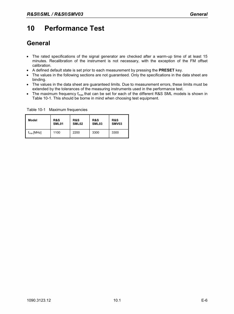
R&S®SML / R&S®SMV03 General
1090.3123.12 10.1 E-6
10 Performance Test
General
• The rated specifications of the signal generator are checked after a warm-up time of at least 15 minutes. Recalibration of the instrument is not necessary, with the exception of the FM offset calibration.
• A defined default state is set prior to each measurement by pressing the PRESET key. • The values in the following sections are not guaranteed. Only the specifications in the data sheet are
binding. • The values in the data sheet are guaranteed limits. Due to measurement errors, these limits must be
extended by the tolerances of the measuring instruments used in the performance test. • The maximum frequency fmax that can be set for each of the different R&S SML models is shown in
Table 10-1. This should be borne in mind when choosing test equipment.
Table 10-1 Maximum frequencies
Model R&S SML01
R&S SML02
R&S SML03
R&S SMV03
fmax [MHz] 1100 2200 3300 3300
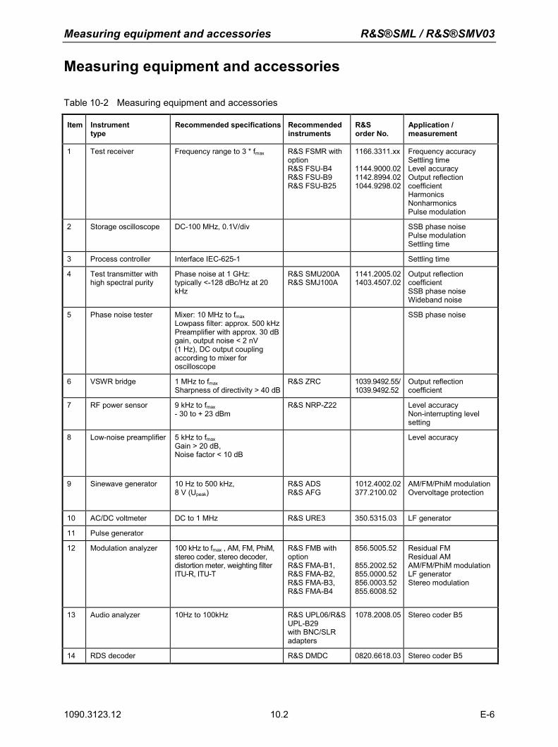
Measuring equipment and accessories R&S®SML / R&S®SMV03
1090.3123.12 10.2 E-6
Measuring equipment and accessories
Table 10-2 Measuring equipment and accessories
Item Instrument type
Recommended specifications Recommended instruments
R&S order No.
Application / measurement
1 Test receiver Frequency range to 3 * fmax R&S FSMR with option R&S FSU-B4 R&S FSU-B9 R&S FSU-B25
1166.3311.xx
1144.9000.021142.8994.021044.9298.02
Frequency accuracy Settling time Level accuracy Output reflection coefficient Harmonics Nonharmonics Pulse modulation
2 Storage oscilloscope
DC-100 MHz, 0.1V/div SSB phase noise Pulse modulation Settling time
3 Process controller Interface IEC-625-1 Settling time
4 Test transmitter with high spectral purity
Phase noise at 1 GHz: typically <-128 dBc/Hz at 20 kHz
R&S SMU200A R&S SMJ100A
1141.2005.021403.4507.02
Output reflection coefficient SSB phase noise Wideband noise
5 Phase noise tester
Mixer: 10 MHz to fmax Lowpass filter: approx. 500 kHzPreamplifier with approx. 30 dB gain, output noise < 2 nV (1 Hz), DC output coupling according to mixer for oscilloscope
SSB phase noise
6 VSWR bridge 1 MHz to fmax Sharpness of directivity > 40 dB
R&S ZRC 1039.9492.55/1039.9492.52
Output reflection coefficient
7 RF power sensor 9 kHz to fmax - 30 to + 23 dBm
R&S NRP-Z22
Level accuracy Non-interrupting level setting
8 Low-noise preamplifier 5 kHz to fmax Gain > 20 dB, Noise factor < 10 dB
Level accuracy
9 Sinewave generator 10 Hz to 500 kHz, 8 V (Upeak)
R&S ADS R&S AFG
1012.4002.02377.2100.02
AM/FM/PhiM modulation Overvoltage protection
10 AC/DC voltmeter DC to 1 MHz R&S URE3 350.5315.03 LF generator
11 Pulse generator
12 Modulation analyzer 100 kHz to fmax , AM, FM, PhiM, stereo coder, stereo decoder, distortion meter, weighting filter ITU-R, ITU-T
R&S FMB with option R&S FMA-B1, R&S FMA-B2, R&S FMA-B3, R&S FMA-B4
856.5005.52
855.2002.52855.0000.52856.0003.52855.6008.52
Residual FM Residual AM AM/FM/PhiM modulationLF generator Stereo modulation
13 Audio analyzer 10Hz to 100kHz R&S UPL06/R&S UPL-B29 with BNC/SLR adapters
1078.2008.05 Stereo coder B5
14 RDS decoder R&S DMDC 0820.6618.03 Stereo coder B5
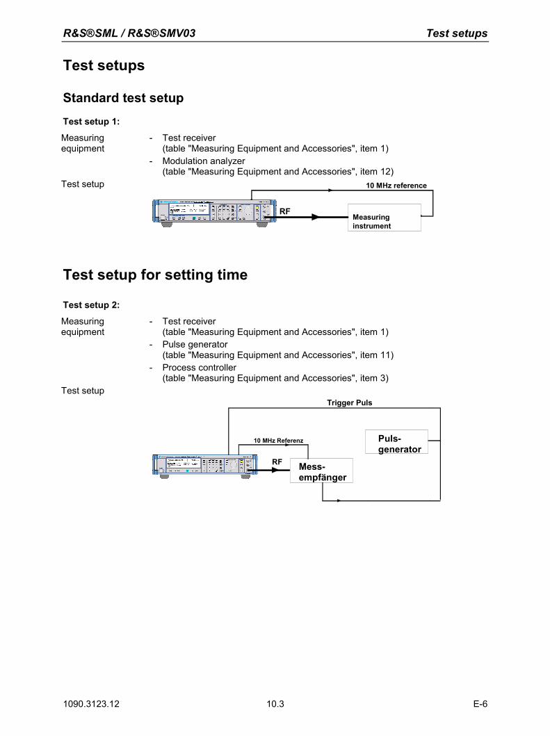
R&S®SML / R&S®SMV03 Test setups
1090.3123.12 10.3 E-6
Test setups
Standard test setup Test setup 1:
Measuring equipment
- Test receiver (table "Measuring Equipment and Accessories", item 1)
- Modulation analyzer (table "Measuring Equipment and Accessories", item 12)
Test setup
RFMeasuringinstrument
10 MHz reference
Test setup for setting time
Test setup 2:
Measuring equipment
- Test receiver (table "Measuring Equipment and Accessories", item 1)
- Pulse generator (table "Measuring Equipment and Accessories", item 11)
- Process controller (table "Measuring Equipment and Accessories", item 3)
Test setup
RF
10 MHz Referenz
Mess- empfänger
Puls-generator
RF
Trigger Puls
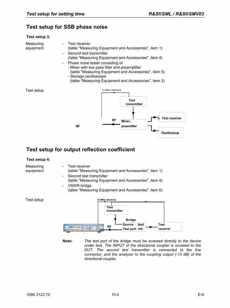
Test setup for setting time R&S®SML / R&S®SMV03
1090.3123.12 10.4 E-6
Test setup for SSB phase noise Test setup 3:
Measuring equipment
- Test receiver (table "Measuring Equipment and Accessories", item 1)
- Second test transmitter (table "Measuring Equipment and Accessories", item 4)
- Phase noise tester consisting of - Mixer with low pass filter and preamplifier (table "Measuring Equipment and Accessories", item 5) - Storage oscilloscope (table "Measuring Equipment and Accessories", item 2)
Test setup
RF
10 MHz reference
Oszilloskop
RF Mixer,preamlifier
Test receiverr
Test transmitter
Test setup for output reflection coefficient
Test setup 4:
Measuring equipment
- Test receiver (table "Measuring Equipment and Accessories", item 1)
- Second test transmitter (table "Measuring Equipment and Accessories", item 4)
- VSWR bridge (table "Measuring Equipment and Accessories", item 6)
Test setup 10 MHz reference
SourceTest port
Refl.out.
Bridge
RF Testreceiver
Test transmitter
Note: The test port of the bridge must be screwed directly to the device under test. The INPUT of the directional coupler is screwed to the DUT. The second test transmitter is connected to the line connector, and the analyzer to the coupling output (-13 dB) of the directional coupler.
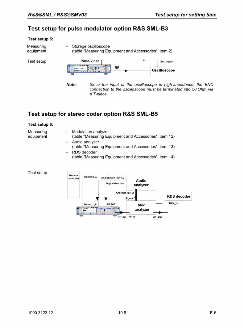
R&S®SML / R&S®SMV03 Test setup for setting time
1090.3123.12 10.5 E-6
Test setup for pulse modulator option R&S SML-B3 Test setup 5:
Measuring equipment
- Storage oscilloscope (table "Measuring Equipment and Accessories", item 2)
Test setup
RF
Ext. trigger
OscilloscopeRF
Pulse/Video
Note: Since the input of the oscilloscope is high-impedance, the BNC connection to the oscilloscope must be terminated into 50 Ohm via a T-piece.
Test setup for stereo coder option R&S SML-B5 Test setup 6:
Measuring equipment
- Modulation analyzer (table "Measuring Equipment and Accessories", item 12)
- Audio analyzer (table "Measuring Equipment and Accessories", item 13)
- RDS decoder (table "Measuring Equipment and Accessories", item 14)
Test setup
Mod.analyzer
RF_out
Audioanalyzer
Processcontroller
RDS decoder
RF_in
Stereo_L,R S/P DIF
L,R_out
AF_out
MPX_in
IEC/IEEE bus Analog Gen_out 1,2
Digital Gen_out
Analyzer_in 1,2
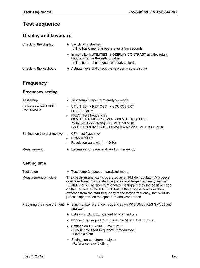
Test sequence R&S®SML / R&S®SMV03
1090.3123.12 10.6 E-6
Test sequence
Display and keyboard
Checking the display Switch on instrument → The basic menu appears after a few seconds
In menu item UTILITIES → DISPLAY CONTRAST use the rotary knob to change the setting value → The contrast changes from dark to light
Checking the keyboard Actuate keys and check the reaction on the display
Frequency
Frequency setting
Test setup Test setup 1, spectrum analyzer mode
Settings on R&S SML / R&S SMV03
- UTILITIES → REF OSC → SOURCE EXT - LEVEL: 0 dBm - FREQ: Test frequencies
60 MHz, 100 MHz, 250 MHz, 600 MHz, 1000 MHz With Ext.Divider Range: 10 MHz, 50 MHz For R&S SML02/03 / R&S SMV03 also: 2200 MHz, 3300 MHz
Settings on the test receiver - CF = test frequency
- SPAN = 20 Hz - Resolution bandwidth = 10 Hz
Measurement Set marker on peak and read off frequency
Setting time
Test setup Test setup 2, spectrum analyzer mode
Measurement principle The spectrum analyzer is operated as an FM demodulator. A process controller transmits the start frequency and target frequency via the IEC/IEEE bus. The spectrum analyzer is triggered by the positive edge on the EOI line of the IEC/IEEE bus. If the process controller then switches from the start frequency to the target frequency, the build-up process appears on the spectrum analyzer screen.
Preparing the measurement Synchronize reference frequencies on R&S SML / R&S SMV03 and analyzer.
Establish IEC/IEEE bus and RF connections
Connect trigger port to EOI line (pin 5) of IEC/IEEE bus.
Settings on R&S SML / R&S SMV03 - Frequency: Start frequency unmodulated - Level: 0 dBm
Settings on spectrum analyzer - Reference level 0 dBm,
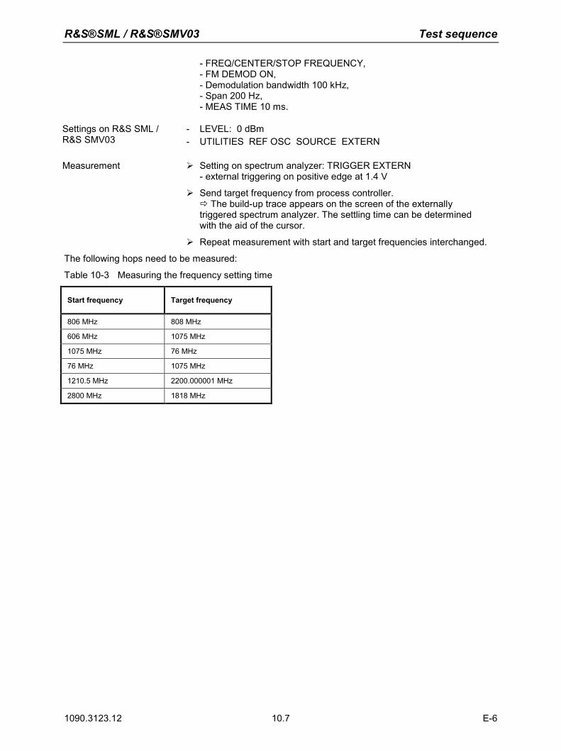
R&S®SML / R&S®SMV03 Test sequence
1090.3123.12 10.7 E-6
- FREQ/CENTER/STOP FREQUENCY, - FM DEMOD ON, - Demodulation bandwidth 100 kHz, - Span 200 Hz, - MEAS TIME 10 ms.
Settings on R&S SML / R&S SMV03
- LEVEL: 0 dBm - UTILITIES REF OSC SOURCE EXTERN
Measurement Setting on spectrum analyzer: TRIGGER EXTERN
- external triggering on positive edge at 1.4 V
Send target frequency from process controller. The build-up trace appears on the screen of the externally triggered spectrum analyzer. The settling time can be determined with the aid of the cursor.
Repeat measurement with start and target frequencies interchanged.
The following hops need to be measured:
Table 10-3 Measuring the frequency setting time
Start frequency Target frequency
806 MHz 808 MHz
606 MHz 1075 MHz
1075 MHz 76 MHz
76 MHz 1075 MHz
1210.5 MHz 2200.000001 MHz
2800 MHz 1818 MHz
Test sequence R&S®SML / R&S®SMV03
1090.3123.12 10.8 E-6
Reference frequency
Internal reference output
Note: Let the R&S SML / R&S SMV03 warm up for at least 2 hours before starting a measurement.
Test setup Connect test receiver (spectrum analyzer mode) to REF EXT output on rear panel of R&S SML / R&S SMV03.
Settings on the test receiver - Center frequency = 10 MHz - Span = 20 Hz - Resolution bandwidth = 10 Hz
Measurement Set marker on peak and read off frequency.
Analysis The frequency deviation must not exceed the sum of the deviations resulting from the frequency error in the rated temperature range and from aging.
External reference input
Test setup Connect test receiver (spectrum analyzer mode) to RF connector on R&S SML / R&S SMV03.
Connect signal generator to REF IN connector on rear panel of R&S SML / R&S SMV03.
Connect references of test receiver and signal generator
Settings on the test receiver - Center frequency = test frequency of R&S SML / R&S SMV03 - Span = 100 Hz - Resolution bandwidth = 10 Hz
Settings on R&S SML / R&S SMV03
- Switch reference oscillator to external
Settings on the signal generator
- Frequency = 10 MHz - Level = 7 dBm
Measurement Set marker on peak and read off frequency
Analysis The frequency deviation must not exceed the sum of the deviations resulting from the frequency error in the rated temperature range and from aging.
R&S®SML / R&S®SMV03 Test sequence
1090.3123.12 10.9 E-6
Spectral purity
Harmonic ratio (harmonic spurious)
Test setup Test setup 1, spectrum analyzer mode
Settings on the R&S SML01
- LEVEL: max. level as data sheet - FREQ: Test frequencies
100 kHz, 120 kHz, 5 MHz, 76 MHz, 100 MHz, 151 MHz, 200 MHz, 255.25 MHz, 300 MHz, 400 MHz, 500 MHz, 605 MHz, 655.25 MHz, 700 MHz, 1100 MHz
Settings on the R&S SML02/03 / R&S SMV03
- LEVEL: max. level as data sheet - FREQ: in addition to the test frequencies for R&S SML01:
1211 MHz, 1700 MHz, 2010 MHz, 2010 MHz, 2200 MHz, 3000 MHz, 3300 MHz
Settings with option B3 Test frequencies for harmonics > 20 MHz
Settings with option B10 Additional test level: max. level as data sheet
Settings on the test receiver - CF = test frequency - Reference level = test level +10 dB, 10 dB/div - SPAN = 300 kHz - Resolution bandwidth = 30 kHz
Measurement First measure the level of the fundamental as reference, then look for signals at double and triple the carrier frequency. When doing so, make sure that the spectrum analyzer is not overloaded.
Analysis The harmonic ratio is the difference in level between the detected harmonic referenced to the output signal from the R&S SML / R&S SMV03 (in dBc = referenced to the carrier)
Spurious suppression (nonharmonic spurious)
Test setup Test setup 1, spectrum analyzer mode
Settings on R&S SML / R&S SMV03
- UTILITIES → REF OSC → SOURCE EXTERN - LEVEL: 13 dBm (R&S SML02/03: 11 dBm) - FREQ:
Test frequencies for spurious 966.052 MHz, 927.2776 MHz, 945.821 MHz, 979.713 MHz, 980.729 MHz, 987.315 MHz, 999.998 MHz, 1022.438 MHz, 1060.872 MHz, 1080.003 MHz, 1086.2 MHz, 1086.663 MHz, 1086.9535 MHz, 1090.28 MHz, 1095.002 MHz, 1098.956 MHz Look in the range ± (10 kHz to 2MHz)
- Test frequencies for mixer spurious 75.9 MHz Look in the region of 875.9 MHz
Settings on the test receiver - Start frequency = test frequency – 5 kHz
- Reference level = test level +3 dB, 10 dB/div - SPAN = 100 kHz - Resolution bandwidth = 1 kHz - Switch on average: 5 samples
Measurement First measure the level of the fundamental as reference, then
Test sequence R&S®SML / R&S®SMV03
1090.3123.12 10.10 E-6
measure the level at any visible spurious.
Analysis The spurious suppression ratio is the difference in level between the detected spurious referenced to the output signal from the R&S SML / R&S SMV03 (in dBc = referenced to the carrier)
Spurious suppression (subharmonic spurious, for R&S SML02/03 / R&S SMV03 only)
Test setup Test setup 1, spectrum analyzer mode
Settings on R&S SML / R&S SMV03
- UTILITIES → REF OSC → SOURCE EXTERN - LEVEL: 11 dBm - FREQ:
Test frequencies for subharmonics 1250 MHz, 1500 MHz, 1800 MHz (frequency double) 1830 MHz, 2100 MHz, 2199 MHz, 2400 MHz (frequency triple) 2660 MHz, 3200 MHz (frequency quadruple)
Settings on the test receiver - Reference level = test level +3 dB, 10 dB/div - Center frequency = test frequency - SPAN = 100 kHz - Resolution bandwidth = 1 kHz - Switch on average: 5 samples - Center frequency = test frequency * 1/2, * 3/2 (frequency double) - Center frequency = test frequency * 1/3, * 2/3, * 4/3 (frequency triple) - Center frequency = test frequency * 1/4, * 1/2, * 3/4, * 5/4 (frequency
quadruple)
Measurement First measure the level of the ground wave as reference, then measure the level at any visible subharmonic.
Analysis The spurious suppression ratio is the difference in level between the detected spurious referenced to the output signal from the R&S SML / R&S SMV03 (in dBc = referenced to the carrier).
Note: The spectrum analyzer setting values are reference values and are dependent on the
analyzer used. The necessary measurement distance must be verified before every measurement.
SSB phase noise
Test setup Test setup 3, spectrum analyzer mode
Settings on R&S SML / R&S SMV03
- UTILITIES → REF OSC → SOURCE EXTERN - LEVEL: 5.1 dBm (or level according to mixer specification) - FREQ: 1 GHz (or any measurement frequency > 200 MHz)
Measurement principle The two test transmitters are set to the measurement frequency and synchronized with 90° phase offset (phase quadrature). The RF carrier is suppressed by mixing at 0 Hz, and the mixer makes use of the phase quadrature in order to deliver a voltage corresponding to the phase -difference between the input signals. This voltage is measured by the spectrum analyzer and can be converted into SSB phase noise.
Measurement Set the level of each test transmitter according to the specifications of
R&S®SML / R&S®SMV03 Test sequence
1090.3123.12 10.11 E-6
the mixer being used.
For calibration purposes lower the level of the DUT by 40 dB and detune one test transmitter by 20 kHz. Check the signal for harmonics; the second and third harmonics must be more than 30 dB below the fundamental. Use the analyzer to measure the reference value at 20 kHz and make a note of this value.
Cancel the detuning and set the phase quadrature. Restore the level of the DUT and detune the phase offset at the auxiliary transmitter. Observe the output voltage from the mixer on the oscilloscope, until the voltage reaches 0.
Read off the noise voltage from the analyzer, normalized to 1 Hz bandwidth (noise level).
Analysis Note the difference compared to the reference level and increase the
offset found by a further 6 dB for the second sideband measured at the same time (correlated) and 40 dB for the level switchover. If the signal-to-noise ratio of the second test transmitter is not at least 10 dB better than that of the DUT, the noise component of the reference transmitter must also be determined and due allowance must be made. → The corrected signal-to-noise ratio is the required measured value. Example: Let the reference level be measured as 12 dBm. At 20 kHz a
noise level of -78 dBm (1 Hz) is determined. The difference is 90 dB. Adding in the correction for the second sideband (6 dB) and the level switchover (40 dB) gives a signal-to-noise ratio of -136 dB or a noise level of -136 dBc (dB referenced to the carrier power).
Wideband noise
Test setup Test setup 1, spectrum analyzer mode
Settings on R&S SML / R&S SMV03
- UTILITIES → REF OSC → SOURCE EXTERN - LEVEL: 5.1 dBm - FREQ:
5 MHz, 10 MHz, 76 MHz, 76.000 000 1 MHz, 151.312 500 1 MHz, 255. 250 000 1 MHz, 605.250 000 MHz, 605.250 000 1 MHz, 700 MHz, 807 MHz, 807.000 000 1 MHz, 950 MHz, 1 076 MHz, 1 076.000 000 1 MHz, 1 100 MHz, 1 250 MHz, 1 800 MHz, 2 010 MHz, 2 200 MHz, 2 655 MHz, 2 655.000 000 1 MHz, 2 800 MHz, 2 800.000 000 1 MHz, 3 300 MHz
Settings on the test receiver - Reference level = 7 dBm
- Center frequency = FREQ (R&S SML) or FREQ + 5 MHz - Span = 50 kHz - MEAS → CHANPWR/ACP → CP/ACP CONFIG → CHANNEL
BANDWITH = 30 kHz
Measurement principle The measurement method is based on the channel power measurement. First the carrier power is determined, then the measurement channel is moved to a corresponding store and the channel power is likewise
Test sequence R&S®SML / R&S®SMV03
1090.3123.12 10.12 E-6
determined. The result is then referenced to 1 Hz bandwidth. The result of this calculation is the value of the broadband noise.
Measurement - Measure the carrier power (PT)- Detune the center frequency by 5 MHz - Measure the channel power (PK)
Analysis The value of the broadband noise is determined from:
⋅−=
][10log10
10
HzChBwPBBNoise
KP
T
Residual FM
Test setup Test setup 1, demodulator mode
Settings on R&S SML / R&S SMV03
- LEVEL: 0 dBm - FREQ:
1 MHz, 20 MHz, 76 MHz, 100 MHz, 300 MHz, 605 MHz, 750 MHz, 900 MHz, 1 100 MHz, 1 211 MHz, 1 700 MHz, 2 200 MHz, 3 300 MHz
Settings on the test receiver - Reference level = 0 dBm
- Center frequency = FREQ (R&S SML) - Demodulation: FM - Detector: RMS - Filter: 20 Hz to 23 kHz
(for the moment measurement must still be carried out with 50 Hz / 100 kHz, since filters are not yet implemented)
Measurement Read off the frequency deviation.
Residual AM
Test setup Test setup 1, demodulator mode
Settings on R&S SML / R&S SMV03
- LEVEL: 0 dBm - FREQ:
5 MHz, 10 MHz, 76 MHz, 76 MHz + 1 Hz, 151.3125001 MHz, 255.2500001 MHz, 605.25 MHz, 605.2500001 MHz, 700 MHz, 807 MHz, 807 MHz + 1 Hz, 960 MHz, 1076 MHz, 1076 MHz + 1 Hz, 1250 MHz, 1800 MHz, 2010 MHz, 2200 MHz, 2655 MHz, 2655 MHz + 1 Hz, 2800 MHz, 2800 MHz + 1 Hz, 3300 MHz
Settings on the test receiver - Reference level = 0 dBm
- Center frequency = FREQ (R&S SML) - Demodulation: AM - Detector: RMS - Filter: 20 Hz to 23 kHz
(for the moment measurement must still be carried out with 50 Hz / 100 kHz, since filters are not yet implemented)
Measurement Read off the residual.
R&S®SML / R&S®SMV03 Test sequence
1090.3123.12 10.13 E-6
Level
Level flatness and level accuracy
Measuring equipment - Test receiver (table "Measuring Equipment and Accessories", item 1) - Power sensor (table "Measuring Equipment and Accessories", item 7) - Low-noise preamplifier (table "Measuring Equipment and
Accessories", item 8)
Measurement method for levels in the measurement range of the power sensor (-25 dBm to +23 dBm) Test setup Test setup 1; connect a power sensor to the RF output connector.
Settings on the R&S SML01
- FREQ: 100 kHz, 500 kHz, 1 MHz, 2 MHz, 3 MHz, 4 MHz, 5 MHz, 5 MHz + 1 Hz, 15 MHz, 25 MHz, every 10 MHz to 1100 MHz
- LEVEL: 13 dBm, 0 dBm with R&S SML-B10 also 23 dBm
Settings on the R&S SML02/03 / R&S SMV03
- FREQ: to 1100 MHz as R&S SML01 from 1105 MHz every 20 MHz to 2200 MHz or 3300 MHz
- LEVEL: 13 dBm, 0 dBm with R&S SML-B10 also +21 dBm
Settings on the test receiver - Power meter mode
ZEROING is carried out before level measurements. Use RF OFF when turning off the level on the R&S SML / R&S SMV03.
Measurement Measure the level at the test frequencies. → The frequency response is the difference between the highest and
the lowest measured value. → The level error is the deviation from the set value.
Measurement method for small levels (-80 dBm to -25 dBm) Caution: A prerequisite for correct measurement is full RF shielding of the components used. Measurement principle A line measurement in RF level mode is carried out at an output level
from the R&S SML / R&S SMV03 of – 25 dBm, and measurements are then carried out this mode down to – 80 dBm.
Test setup Test setup 1
Settings on the R&S SML01
- FREQ: Frequency that shows the largest deviation at 0 dBm 120 kHz, 50 MHz, 1100 MHz
- LEVEL: 6 dBm, 5 dB steps as far as – 80 dBm
Test sequence R&S®SML / R&S®SMV03
1090.3123.12 10.14 E-6
Settings on the R&S SML02/03 / R&S SMV03
- FREQ: to 1100 MHz as R&S SML01 from 1105 MHz every 20 MHz to 2200 MHz or 3300 MHz
Settings on the test receiver - RF LEVEL mode
- Center frequency = FREQ (R&S SML) - Execute function CAL ABS POWER
→ Record the reference value with the aid of the power sensor. → Now connect the RF output from the R&S SML / R&S SMV03 to
the RF connector of the receiver. → The receiver now measures the power via the RF connector and
determines a correction factor which is taken into account in the subsequent measurements. Caution: This correction value applies to the set measurement
frequency only.
Measurement Measure the level at the test frequencies. → The frequency response is the difference between the highest and
the lowest measured value. → The level error is the deviation from the set value.
Measurement method for very small levels (<-80 dBm) Caution: A prerequisite for correct measurement is full RF shielding of the components used. Test setup Test setup 1; a low-noise preamplifier must be connected between the
R&S SML / R&S SMV03 and the test receiver.
Measurement Having measured a level, continue by carrying out a calibration. → This enables levels down to the lowest limits set for the R&S SML /
R&S SMV03 to be measured.
Output reflection coefficient
Test setup Test setup 4, spectrum analyzer mode.
Test method Since the VSWR of a source must be measured, a purely passive measurement using the VSWR bridge is possible only at levels where the output impedance of the electronic attenuator defines the VSWR. At higher levels the influence of the level control must be included. This is done with the aid of an auxiliary transmitter which transmits a wave into the DUT. This wave has a slightly offset carrier frequency (the difference frequency within the control bandwidth of the level control) and is superimposed on the decaying wave of the DUT. At an ideal internal impedance only the decaying wave of the DUT flows back into the bridge, whilst at an internal impedance that deviates from the ideal there is superposition of the two components. The frequency offset gives rise to a beat. From the amplitude ratio of this beat, conclusions can be drawn with regard to the VSWR.
Settings on the R&S SML01
- FREQ: 9 MHz, 50 MHz, 200 MHz, 350 MHz, every 20 MHz to 1100 MHz- LEVEL: 10 dBm, 5 dBm, 0 dBm, - 10 dBm
R&S®SML / R&S®SMV03 Test sequence
1090.3123.12 10.15 E-6
Settings on the R&S SML02/03 / R&S SMV03
- FREQ: 9 MHz, 50 MHz, 200 MHz, 350 MHz, every 20 MHz to 2200 MHz or 3300 MHz
- LEVEL: 8 dBm, 3 dBm, - 2 dBm, - 7 dBm
Settings on the test receiver - Spectrum analyzer mode - Center frequency = FREQ (R&S SML) - Span = 0 Hz - Reference level = LEVEL (R&S SML) - Resolution bandwidth and video bandwidth = 10 kHz - Linear level scale - Sweep time = 30 ms
Settings on the second test transmitter
- Frequency = FREQ (R&S SML) – 100 Hz - RF OFF first
Measurement Bring the line displayed on the test receiver due to changing the reference level to roughly the middle of the screen, read off the level as the reference level and make a note of it.
Unscrew the bridge from the R&S SML / R&S SMV03 and increase the level on the second test transmitter until the reference level is again being measured on the analyzer.
Screw the bridge or directional coupler back onto the R&S SML / R&S SMV03. → The spectrum analyzer now shows a more or less wavy line which represents the VSWR of the R&S SML / R&S SMV03. To calculate the VSWR use the formula VSWR = umax / umin containing the maximum and minimum voltages.
Passive measurement of the VSWR for R&S SML / R&S SMV03 output levels below –25 dBm Settings on R&S SML / R&S SMV03
- FREQ: (far from the measurement frequency, > 10 MHz) 9 MHz, 50 MHz, 200 MHz, 350 MHz, every 20 MHz to 1100 MHz or 2200 MHz / 3300 MHz (R&S SML02/03)
- LEVEL: - 30 dBm
Settings on the second test transmitter
- Frequency = FREQ (R&S SML) - Level = 10 dBm
Measurement Unscrew the VSWR bridge from the DUT and note the level measured on the analyzer as the reference value.
Screw the bridge or directional coupler back on again and determine the new level on the analyzer. → The voltage ratio test level / reference level is the output reflection coefficient r of the DUT.
Use the formula VSWR = (1 + r) / ( 1 – r) to determine the standing wave ratio (VSWR).
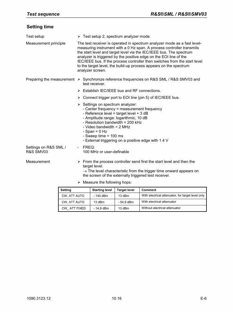
Test sequence R&S®SML / R&S®SMV03
1090.3123.12 10.16 E-6
Setting time
Test setup Test setup 2, spectrum analyzer mode.
Measurement principle The test receiver is operated in spectrum analyzer mode as a fast level-measuring instrument with a 0 Hz span. A process controller transmits the start level and target level via the IEC/IEEE bus. The spectrum analyzer is triggered by the positive edge on the EOI line of the IEC/IEEE bus. If the process controller then switches from the start level to the target level, the build-up process appears on the spectrum analyzer screen.
Preparing the measurement Synchronize reference frequencies on R&S SML / R&S SMV03 and test receiver.
Establish IEC/IEEE bus and RF connections.
Connect trigger port to EOI line (pin 5) of IEC/IEEE bus.
Settings on spectrum analyzer: - Center frequency = measurement frequency - Reference level = target level + 3 dB - Amplitude range: logarithmic, 10 dB - Resolution bandwidth = 200 kHz - Video bandwidth = 2 MHz - Span = 0 Hz - Sweep time = 100 ms - External triggering on a positive edge with 1.4 V
Settings on R&S SML / R&S SMV03
- FREQ: 100 MHz or user-definable
Measurement From the process controller send first the start level and then the target level. → The level characteristic from the trigger time onward appears on the screen of the externally triggered test receiver.
Measure the following hops:
Setting Starting level Target level Comment
CW, ATT AUTO - 140 dBm 13 dBm With electrical attenuator, for target level only
CW, ATT AUTO 13 dBm - 54,9 dBm With electrical attenuator
CW_ ATT FIXED - 14,9 dBm 13 dBm Without electrical attenuator
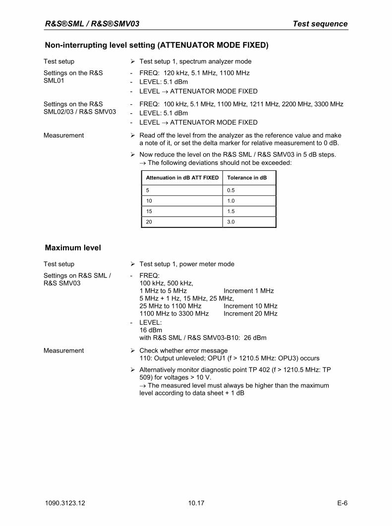
R&S®SML / R&S®SMV03 Test sequence
1090.3123.12 10.17 E-6
Non-interrupting level setting (ATTENUATOR MODE FIXED)
Test setup Test setup 1, spectrum analyzer mode
Settings on the R&S SML01
- FREQ: 120 kHz, 5.1 MHz, 1100 MHz - LEVEL: 5.1 dBm - LEVEL → ATTENUATOR MODE FIXED
Settings on the R&S SML02/03 / R&S SMV03
- FREQ: 100 kHz, 5.1 MHz, 1100 MHz, 1211 MHz, 2200 MHz, 3300 MHz - LEVEL: 5.1 dBm - LEVEL → ATTENUATOR MODE FIXED
Measurement Read off the level from the analyzer as the reference value and make a note of it, or set the delta marker for relative measurement to 0 dB.
Now reduce the level on the R&S SML / R&S SMV03 in 5 dB steps. → The following deviations should not be exceeded:
Attenuation in dB ATT FIXED Tolerance in dB
5 0.5
10 1.0
15 1.5
20 3.0
Maximum level
Test setup Test setup 1, power meter mode
Settings on R&S SML / R&S SMV03
- FREQ: 100 kHz, 500 kHz, 1 MHz to 5 MHz Increment 1 MHz 5 MHz + 1 Hz, 15 MHz, 25 MHz, 25 MHz to 1100 MHz Increment 10 MHz 1100 MHz to 3300 MHz Increment 20 MHz
- LEVEL: 16 dBm with R&S SML / R&S SMV03-B10: 26 dBm
Measurement Check whether error message
110: Output unleveled; OPU1 (f > 1210.5 MHz: OPU3) occurs
Alternatively monitor diagnostic point TP 402 (f > 1210.5 MHz: TP 509) for voltages > 10 V. → The measured level must always be higher than the maximum level according to data sheet + 1 dB
Test sequence R&S®SML / R&S®SMV03
1090.3123.12 10.18 E-6
Overvoltage protection
Measuring equipment - Sinewave generator (table "Measuring Equipment and Accessories", item 9)Test setup Connect the sinewave generator to the RF output of the R&S SML /
R&S SMV03.
Settings on R&S SML / R&S SMV03
- FREQ: 100 MHz
- LEVEL: - 140 dBm
Settings on the sinewave generator
- FREQ: 20 kHz
- Output impedance = 50 Ohm - Level = 1 V - Level offset = ± 5 V
Measurement Increase the output level of the sinewave generator to a maximum of 10 V (EMF) → The overvoltage protection must respond to a voltage (offset + EMF/2) > 3.7 V and < 7.5 V for both polarities.
Internal modulation generator Note: The setting time refers purely to computer time and therefore does not need to be
measured. Level accuracy
Measuring equipment - AC voltmeter (table "Measuring Equipment and Accessories", item 10)
Test setup Connect AC voltmeter to LF connector of R&S SML / R&S SMV03
Settings on R&S SML / R&S SMV03
- LF OUTPUT STATE ON - LF OUTPUT LFGen 1 kHz - LF OUTPUT VOLTAGE:
1 mV, 10 mV, 100 mV, 1 V, 4 V
Measurement Measure output level
Frequency response
Measuring equipment - AC voltmeter (table "Measuring Equipment and Accessories", item 10) Test setup Connect AC voltmeter to LF connector of R&S SML / R&S SMV03.
Settings on R&S SML / R&S SMV03
- LF OUTPUT STATE ON - LF OUTPUT VOLTAGE:
1 V, 4 V - LF OUTPUT LFGen:
10 Hz to 500 kHz, 5 reference values / decade
Measurement Measure the frequency response → The frequency response is the difference between the highest and lowest level.
R&S®SML / R&S®SMV03 Test sequence
1090.3123.12 10.19 E-6
Frequency accuracy and total harmonic distortion
Measuring equipment - Test receiver (table "Measuring Equipment and Accessories", item 1) synchronized with R&S SML / R&S SMV03
Test setup Connect the audio input from the receiver to the LF connector of the R&S SML / R&S SMV03.
Settings on R&S SML / R&S SMV03
- LF OUTPUT STATE ON - LF OUTPUT VOLTAGE:
1 V, 4 V - LF OUTPUT LFGen:
for frequency accuracy: 100 Hz, 1 kHz, 33.33 kHz, 1 MHz for total harmonic distortion: 20 Hz, 50 Hz, 100 Hz to 100 kHz: 3 values / decade each
Settings on the sinewave generator
- FREQ: 20 kHz
- Output impedance = 50 Ohm - Level = 1 V - Level offset = ± 5 V
Measurement Read off actual frequency from test receiver
Read off THD value from test receiver Total harmonic distortion is calculated by the formula
%10010
1
20
•=−THDk
Amplitude modulation
AM deviation setting
Test setup Test setup 1, demodulator mode
Settings on the R&S SML01
- LEVEL: 2.1 dBm, 5 dBm, 8 dBm with R&S SML-B10: 15 dBm
- FREQ: 100 kHz, 5.1 MHz, 1100 MHz
- MODULATION → AM → AM DEPTH: 10 % to 95 % in 20 steps AM SOURCE LFGen LFGenFreq = 1 kHz
Settings on the R&S SML02/03 / R&S SMV03
- LEVEL: 0.1 dBm, 5 dBm, 8 dBm with R&S SML-B10: 15 dBm
- FREQ: in addition to the test frequencies for R&S SML01 1211 MHz, 2200 MHz, 2800 MHz, 3300 MHz
- MODULATION → AM → AM DEPTH: 10 % to 95 % in 20 steps AM SOURCE LFGen LFGenFreq = 1 kHz
Test sequence R&S®SML / R&S®SMV03
1090.3123.12 10.20 E-6
Settings with option B3 - FREQ: only test frequencies > 10 MHz
Settings on the test receiver - Demodulation: AM
- Detector: Peak
Measurement First, at AM deviation test frequencies and with test levels 2.1 dBm (R&S SML02/03: 0.1 dBm) and 5 dBm, test the deviation setting from 10 % to 95 %. Then at deviation = 80 % and test level 8 dBm (R&S SML02/03: 6 dBm) traverse the frequency range from 100 kHz to fmax in steps of 60 MHz.
Read off the deviation from the test receiver.
AM frequency response
Test setup Test setup 1, demodulator mode
Settings on the R&S SML01
- LEVEL: 3 dBm with R&S SML-B10: 13 dBm
- FREQ: 500 kHz, 5.1 MHz, 1100 MHz
- MODULATION → AM → AM DEPTH: 60 % AM SOURCE: LFGen LFGenFreq = 10 Hz to 50 kHz
Settings on the R&S SML02/03 / R&S SMV03
- LEVEL: 3 dBm with R&S SML-B10: 13 dBm
- FREQ: in addition to the test frequencies for R&S SML01 1211 MHz, 2200 MHz, 3300 MHz
- MODULATION → AM → AM DEPTH: 60 % AM SOURCE: LFGen LFGenFreq = 10 Hz to 50 kHz
Settings with option B3 - FREQ:
only test frequencies > 10 MHz -
Settings on the test receiver - Demodulation: AM - Detector: Peak
Measurement Determine the modulation frequency response by varying the LF generator frequency.
Repeat the measurement using an external sinewave generator with the setting MODULATION → AM → AM SOURCE: EXT (sinewave generator setting: 1 Vs).
The modulation frequency response is the difference between the highest and lowest modulation depth.
R&S®SML / R&S®SMV03 Test sequence
1090.3123.12 10.21 E-6
AM total harmonic distortion
Test setup Test setup 1, demodulator mode
Settings on the R&S SML01
- LEVEL: 2.1 dBm, 6 dBm with R&S SML-B10: 16 dBm
- FREQ: 100 kHz, 5 MHz, 5.1 MHz, 76 MHz, 100 MHz, 200 MHz, 500 MHz, 800 MHz, 1100 MHz
- MODULATION → AM → AM DEPTH: 30 %, 80 % AM SOURCE: LFGen LFGenFreq = 1 kHz
Settings on the R&S SML02/03 / R&S SMV03
- LEVEL: 0.1 dBm, 6 dBm with R&S SML-B10: 16 dBm
- FREQ: in addition to the test frequencies for R&S SML01 > 5 MHz: 2000 MHz, 2200 MHz, 2800 MHz, 3000 MHz
- MODULATION → AM → AM DEPTH: 30 %, 80 % AM SOURCE: LFGen LFGenFreq = 1 kHz
Settings with option B3 - FREQ:
only test frequencies > 10 MHz
Settings on the test receiver - Demodulation: AM - Detector: Peak - Activate THD & SINAD
Measurement Read off the THD value from the test receiver and use the formula
%10010
1
20
•=−THDk
to convert to the total harmonic distortion. With settings of 2.1 dBm (R&S SML02/03: 0.1 dBm) with deviation = 30 % and 6 dBm with deviation = 80 %, simply measure across the frequency range.
Test sequence R&S®SML / R&S®SMV03
1090.3123.12 10.22 E-6
Spurious PhiM in AM
Test setup Test setup 1, demodulator mode
Settings on the R&S SML01
- LEVEL: 2.1 dBm with R&S SML-B10: 12.1 dBm
- FREQ: 77 MHz, 1100 MHz
- MODULATION → AM → AM DEPTH: 30 % AM SOURCE: LFGen LFGenFreq = 1 kHz
Settings on the R&S SML02/03 / R&S SMV03
- LEVEL: 8 dBm with R&S SML-B10: 18 dBm
- FREQ: in addition to the test frequencies for R&S SML01: 2200 MHz, 3300 MHz
- MODULATION → AM → AM DEPTH: 30 % AM SOURCE: LFGen LFGenFreq = 1 kHz
Settings on the test receiver - Demodulation: PM
- Detector: Peak
Measurement On the test receiver measure the resulting phase modulation with 100 kHz lowpass filter and peak analysis.
Frequency modulation
FM deviation setting
Test setup Test setup 1, demodulator mode
Settings on R&S SML / R&S SMV03
- LEVEL: 0 dBm - FREQ: 1 GHz - MODULATION → FM → FM DEVIATION: 100 kHz
FM SOURCE: LFGen LFGenFreq = 1 kHz
Settings on the test receiver - Demodulation: FM
- Detector: Peak - Filter: 20 Hz to 23 kHz
(for the moment measurement must still be carried out with 50 Hz / 100 kHz, since filters are not yet implemented)
Measurement Read off the frequency deviation from the test receiver
Note: Since the R&S SML / R&S SMV03 has a purely digital deviation generator, it is adequate
to test its functionality by taking a measurement at one deviation setting and one frequency only.
R&S®SML / R&S®SMV03 Test sequence
1090.3123.12 10.23 E-6
FM frequency response
Test setup Test setup 1, demodulator mode
Settings on R&S SML / R&S SMV03
- LEVEL: 0 dBm - FREQ: 1 GHz - MODULATION → FM → FM DEVIATION: 100 kHz
FM SOURCE: LFGen LFGenFreq = 10 Hz to 100 kHz
Settings on the test receiver - Demodulation: FM
- Detector: Peak
Measurement Determine the modulation frequency response by varying the generator frequency of the built-in LF generator in the FM menu from 10 Hz to 100 kHz. The modulation frequency response is the difference between the lowest and highest measured deviation.
Note: Since there is no difference between the frequency response in FM and PhiM, there is no
need to measure the broad FM loop. The broad PhiM loop can be measured on the spectrum analyzer and this is in fact easier to do.
FM total harmonic distortion
Test setup Test setup 1, demodulator mode
Settings on R&S SML / R&S SMV03
- LEVEL: 0 dBm - FREQ:
605.5 MHz, 650 MHz, 700 MHz, 750 MHz, 807 MHz - MODULATION → FM → FM DEVIATION: see table
FM SOURCE: LFGen LFGenFreq = 1 kHz
Settings on the test receiver - Demodulation: FM
- Detector: Peak - Activate THD & SINAD
Measurement Read off the THD value from the test receiver and use the formula
%10010
1
20
•=−THDk
to convert to the total harmonic distortion.
Carrier freq. [MHz] FM deviation [kHz]
50 500
100 75
200 125
400 250
Test sequence R&S®SML / R&S®SMV03
1090.3123.12 10.24 E-6
Spurious AM in FM
Test setup Test setup 1, demodulator mode
Settings on the R&S SML01
- LEVEL: 0 dBm - FREQ:
10 MHz, 75 MHz, 100 MHz, 300 MHz, 500 MHz, 800 MHz, 1100 MHz- MODULATION → FM → FM DEVIATION: 40 kHz
FM SOURCE: LFGen LFGenFreq = 1 kHz
-Settings on the R&S SML02/03 / R&S SMV03
- LEVEL: 0 dBm - FREQ:
in addition to R&S SML01 test frequencies: 1211 MHz, 1500 MHz, 1818 MHz, 2200 MHz, 3300 MHz
- MODULATION → FM → FM DEVIATION: 40 kHz FM SOURCE: LFGen LFGenFreq = 1 kHz
-Settings on the test receiver - Demodulation: AM
- Detector: RMS - Filter: 20 Hz to 23 kHz
(for the moment measurement must still be carried out with 50 Hz / 100 kHz, since filters are not yet implemented)
Measurement Set test frequencies on the R&S SML / R&S SMV03 and read off the
AM spurious deviation from the test receiver.
Carrier frequency deviation in FMDC
Test setup Test setup 1, spectrum analyzer mode
Settings on R&S SML / R&S SMV03
- UTILITIES → CALIB → FM OFFSET - UTILITIES → REF OSC → SOURCE: EXTERN - LEVEL: 0 dBm - FREQ: 1000 MHz - MODULATION → MODE: FM int, FM ext AC, FM ext DC, FM two
tone FM SOURCE: LFGen LFGenFreq = 1 kHz FM DEVIATION: 500 kHz
Settings on the test receiver - Center frequency = FREQ (R&S SML)
- Span = 1kHz
Measurement Set the specified FM modes one by one and use Marker → Peak to determine the frequency. The difference compared to the set RF frequency on the R&S SML / R&S SMV03 is the center frequency deviation.
Note: This value is not specified, but is typically < 0.1 % of the set deviation and is therefore <
500 Hz at a set deviation of 500 kHz.
R&S®SML / R&S®SMV03 Test sequence
1090.3123.12 10.25 E-6
Crosstalk attenuation in FM stereo
Test setup Test setup 1 with modulation analyzer
Connect the AF1 connector on the stereo coder to the MOD input on the R&S SML / R&S SMV03
Settings on R&S SML / R&S SMV03
- LEVEL 0 dBm - MODULATION FM FM DEVIATION 46.5 kHz
FM SOURCE EXT EXT COUPLING DC
- FREQ Test frequency stereo Test frequencies: 87 MHz, 98 MHz, 108 MHz
Setting on the modulation analyzer
Switch on 1 kHz stereo signal on stereo coder, set level of useful signal to 40 kHz peak deviation and level of pilot tone to 6.5 kHz peak deviation. Demodulation: FM STEREO CHANNEL: L or R DETECTOR RMS FILTER: 10 Hz to 100 kHz Relative deviation measurement
Measurement Switch on the left channel on the stereo coder and carry out a relative measurement. Then switch to the right channel on the demodulator and read off the crosstalk attenuation. Then carry out the same measurement with the right channel.
Total harmonic distortion in FM stereo
Test setup See measurement of crosstalk attenuation in FM stereo
Settings on R&S SML / R&S SMV03
- See measurement of crosstalk attenuation in FM stereo
Setting on the modulation analyzer
- Stereo signal as for crosstalk attenuation measurement - Demodulation: FM STEREO - CHANNEL: L or R - DETECTOR RMS - FILTER: 10 Hz to 100 kHz - AUDIO: Switch on harmonic distortion meter
Measurement Read off harmonic distortion from modulation analyzer
Carry out measurement for left and right channels
Signal-to-noise ratio in FM stereo
Test setup See measurement of crosstalk attenuation in FM stereo
Settings on R&S SML / R&S SMV03
- See measurement of crosstalk attenuation in FM stereo
Test sequence R&S®SML / R&S®SMV03
1090.3123.12 10.26 E-6
Setting on the modulation analyzer
- Stereo signal as for crosstalk attenuation measurement - Demodulation: FM STEREO - CHANNEL: L or R - FILTER: CCIR WT or UNWT - DETECTOR RMS - Relative deviation measurement - DEEMPHASIS 50 µs
Measurement Switch on the left or right channel on the stereo coder and carry out a relative measurement. Then switch off the useful signal on the stereo coder and read off the S/N ratio. Carry out this measurement for both filters (weighted and unweighted). Then switch on the right channel and repeat the same measurement.
Phase modulation
PhiM deviation setting
Test setup Test setup 1, demodulator mode
Settings on R&S SML / R&S SMV03
- LEVEL: 0 dBm - FREQ: 1 GHz - MODULATION → PhiM → PhiM DEVIATION: 5 rad
PhiM SOURCE: LFGen LFGenFreq = 1 kHz
Settings on the test receiver - Demodulation: PhiM
- Detector: Peak - Filter: 20 Hz to 23 kHz
(for the moment measurement must still be carried out with 50 Hz / 100 kHz, since filters are not yet implemented)
Measurement Read off the phase deviation from the test receiver
Note: Since the R&S SML / R&S SMV03 has a purely digital deviation generator, it is adequate
to test its functionality by taking a measurement at one deviation setting and one frequency only.
R&S®SML / R&S®SMV03 Test sequence
1090.3123.12 10.27 E-6
PhiM frequency response
Test setup Test setup 1, demodulator mode
Settings on R&S SML / R&S SMV03
- LEVEL: 0 dBm - FREQ: 1 GHz - MODULATION → PhiM → PhiM DEVIATION: 0.5 rad
FM SOURCE: LFGen LFGenFreq = 10 Hz to 100 kHz / 500 kHz PhiM BANDWIDTH STANDARD / WIDE
Settings on the test receiver - Demodulation: PhiM
- Detector: Peak
Measurement Determine the modulation frequency response by varying the generator frequency of the built-in LF generator in the PhiM menu from 10 Hz to 100 kHz / 500 kHz. The modulation frequency response is the difference between the lowest and highest measured deviation.
Note: Since the frequency response is the same in FM and PhiM, the standard PhiM loop can be
measured in the same way as the FM frequency response.
PhiM total harmonic distortion
Test setup Test setup 1, demodulator mode
Settings on R&S SML / R&S SMV03
- LEVEL: 0 dBm - FREQ: 1075 MHz - MODULATION → PhiM → PhiM DEVIATION: 5 rad
PhiM SOURCE: LFGen LFGenFreq = 1 kHz
Settings on the test receiver - Demodulation: PhiM
- Detector: Peak - Activate THD & SINAD
Measurement Read off the THD value from the test receiver and use the formula %100
10
1
20
•=−THDk
to convert to the total harmonic distortion.
Test sequence R&S®SML / R&S®SMV03
1090.3123.12 10.28 E-6
Pulse modulation (option R&S SML-B3)
On/off ratio
Test setup Test setup 1, spectrum analyzer mode
Settings on the R&S SML01
- LEVEL: 10 dBm - FREQ: 1000 MHz - MODULATION → PULSE → PULSE SOURCE: OFF
Settings on the R&S SML02/03 / R&S SMV03
- LEVEL: 10 dBm - FREQ:
in addition to R&S SML01 test frequency: 2000 MHz, 3300 MHz
- MODULATION → PULSE → PULSE SOURCE: OFF
Settings on the test receiver - Center frequency = test frequency - Span = 20 kHz - Reference level = 10 dBm - Marker Peak
Measurement - Read off the ON level from the spectrum analyzer and make a note of it.
Settings on R&S SML / R&S SMV03
- MODULATION → PULSE → PULSE SOURCE: EXT Make sure the pulse input is not connected.
Settings on the test receiver - Reference level = -50 dBm
- Switch on average: 5 samples - Marker Peak
Measurement Read off the OFF level from the spectrum analyzer and make a note of it.
The on/off ratio is calculated from level ON – level OFF. Repeat the measurement for all test frequencies.
R&S®SML / R&S®SMV03 Test sequence
1090.3123.12 10.29 E-6
Dynamic characteristics
Rise/fall time
Test setup Test setup 5
Settings on R&S SML / R&S SMV03
- LEVEL: 10 dBm - FREQ: 53 MHz - MODULATION → PULSE → PULSE SOURCE: PULSE GEN
PULSE PERIOD: 0.100 us PULSE WIDTH: 0.060 us
- PULSE OUTPUT → PULSE SOURCE: VIDEO
Settings on the oscilloscope - Trigger EXT - Probe 1x - X: 5 ns/div - Y: 5 V/div - Persistence approx. 1 s (when possible)
Measurement Measure rise/fall time in 10 % - 90 % of pulse packets
Video crosstalk
Test setup Test setup 5
Settings on R&S SML / R&S SMV03
- LEVEL: 10 dBm - FREQ: 1000 MHz - ATT FIXED - LEVEL: - 100 dBm - MODULATION → PULSE → PULSE SOURCE: PULSE GEN
PULSE PERIOD: 0.100 us PULSE WIDTH: 0.060 us
- PULSE OUTPUT → PULSE SOURCE: VIDEO
Settings on the oscilloscope - Trigger EXT - Probe 1x - X: 10 ns/div - Y: 10 mV/div - Persistence approx. 1 s (when possible)
Measurement Measure video USS
Test sequence R&S®SML / R&S®SMV03
1090.3123.12 10.30 E-6
Stereo modulation (option R&S SML-B5)
Frequency response
Test setup Test setup 6 Settings on R&S SML / R&S SMV03
- PRESET - FREQ 100MHz - LEVEL 0 dBm - MODULATION STEREO SOURCE LFGEN (or EXT L/R)
MODE L (or MODE R)
Setting on UPL - GEN: - INSTRUMENT ANALOG: Channel(s) 1 (or 2) - FUNCTION Sine - FUNCTION Frequency = 1kHz - FUNCTION Voltage = 0.707V
Setting on FMB - DEMODULATOR FM-STEREO - CHANNEL L (or R) - RELATIVE
Measurement Set the respective LF generator (R&S SML or UPL) to 500Hz and measure the reference level (MEAS-REF). Then traverse the LF gen. from 20Hz to 15kHz and record the frequency response in all four combinations (internal L, internal R, external L, external R).
Total harmonic distortion and channel separation
Test setup Test setup 6
Settings on R&S SML / R&S SMV03
- PRESET - FREQ Measurement frequency
Measurement frequency: 10.7MHz, 66 MHz, 76MHz, 87MHz, 98MHz, 110MHz
- LEVEL 0 dBm - MODULATION STEREO SOURCE EXT L/R,
MODE L != R - AF = 1kHz.
Setting on UPL - FILE: - LOAD INSTRUMENT STATE: Mode = Default - GEN: - INSTRUMENT ANALOG: Channel(s) 1 (or 2) - FUNCTION: Voltage = 0.707 V - ANLR: - INSTRUMENT: Channel(s) 1 & 2 - INSTRUMENT: Ch1, Ch2 Imped = 600 Ohm - FREQ / PHASE: Meas Time = Precision - FUNCTION: RMS & S/N - FUNCTION: Unit Ch1, Ch2 = dBr - FUNCTION: Reference Value = STORE Ch1 (or Ch2)
R&S®SML / R&S®SMV03 Test sequence
1090.3123.12 10.31 E-6
Setting on FMB - DEMODULATOR FM-STEREO - CHANNEL L (or R) - NOISE FILTER OFF - ABSOLUTE - MAN RANGE dBm - RANGE 12dBm - AUDIO DIST-SINAD
Measurement Channel separation: First note the level of the AF signal on the UPL in channel 1 as reference, then switch the source to channel 2 and measure level of crosstalk 2 -> 1. Carry out the same in reverse and measure level of crosstalk 1 -> 2. Limit values according to data sheet.
Read off harmonic distortion from the FMB, limit values according to data sheet.
Signal-to-noise ratio
Test setup Test setup 6
Settings on R&S SML / R&S SMV03
- PRESET - FREQ Measurement frequency
Measurement frequency: 10.7 MHz, 66 MHz, 76 MHZ, 98 MHz, 87 MHz, 110 MHz
- LEVEL 0 dBm - MODULATION STEREO, EXT L,R - MODE L!=R - MPX-Deviation 67.5kHz (acc. IEC 60315-4)
Setting on FMB - DEMODULATION FM-STEREO - INTERN - NOISE FILTER ON - MAN RANGE - RANGE 12dBm - DEEMPHASIS 50us
Setting on UPL - FILE: - LOAD INSTRUMENT STATE: Mode = Default - GEN: - FUNCTION: Voltage = 0.707V - ANLR: - INSTRUMENT: Channels = 1&2 - INSTRUMENT: Ch1, Ch2 Imped = 600Ohm - FREQ / PHASE: Meas Time = Precision - FILTER: CCIR wtd, CCIR unwtd, A Weighting - FUNCTION: RMS & S/N, Q Pk & S/N - FUNCTION: S/N Sequ = ON
Measurement The following filter/detector combinations need to be measured: CCIR-Weighted / Quasipeak CCIR-Unweighted / RMS A-Weighted / RMS
The data sheet values need to be checked.
Test sequence R&S®SML / R&S®SMV03
1090.3123.12 10.32 E-6
MPX deviation, pilot tone level and RDS subcarrier
Test setup Test setup 6
Settings on R&S SML / R&S SMV03
- PRESET - FREQ Measurement frequency - LEVEL 0 dBm - MODULATION STEREO, Source LFGEN, AF=1kHz - ARI State ON - ARI Identification OFF - Measurement frequency: 10.7MHz, 66MHz, 76MHz, 87MHz,
98MHz, 110MHz
Settings on FMB - DEMODULATOR FM-STEREO - ABSOLUTE - DETECTOR +-PEAK/2 - CHANNEL L, PILOT, MORE CARR 57kHz
Measurement Read off the respective deviation from the FMB Check to tol. < 2.5%, for ARI < 6%
Preemphasis
Test setup Test setup 6
Settings on R&S SML / R&S SMV03
- PRESET - FREQ 98MHz - LEVEL 0 dBm - MODULATION STEREO, Source intern LFGEN - MODE L=R - MPX-Hub 10 kHz - PREEMPHASE OFF / 50 us / 75 us
Setting on FMB - DEMODULATOR FM-STEREO - RELATIVE - UNIT dBm - DETECTOR +-PEAK/2 - CHANNEL L
Measurement Note the reference level at preemphasis OFF, AF = 100 Hz
AF = 15 kHz Preemphasis 50us: Target level = +13.66dB Preemphasis 75us: Target level = +17.07dB Check manufacture tol. < 0.5dB
R&S®SML / R&S®SMV03 Test sequence
1090.3123.12 10.33 E-6
Digital S/P Dif interface
Test setup
Test setup 6
Settings on R&S SML / R&S SMV03
- PRESET - FREQ 98MHz - LEVEL 0 dBm - MODULATION STEREO, Source S/P-DIF - MODE L!=R
Setting on FMB - DEMODULATOR FM-STEREO - ABSOLUTE - DETECTOR +-PEAK/2 - CHANNEL L, R
Setting on UPL - GEN INSTRUMENT DIGITAL - Channel 1=2 - Unbal Out AUDIO OUT - Sample Frequency 32kHz, 44.1kHz, 48kHz - FUNCTION STEREO SINE - Freq. Mode FREQ CH1&2 - Volt Mode VOLT CH1&2 - Freq Ch.1 1kHz - Freq Ch.2 0.5kHz - Volt Ch.1 0.707 FS - Volt Ch.2 0.707 FS
Measurement On the FMB, check the set AF and read off the MPX deviation for the audio signal Check the tol. < 2.5 %
RDS function
Test setup Test setup 6
Settings on R&S SML / R&S SMV03
- PRESET - FREQ 98MHz - LEVEL 0 dBm - MODULATION STEREO, Source LFGEN, AF=1kHz - ARI State ON - RDS State ON
Setting on FMB - DEMODULATOR FM-STEREO - CHANNEL MPX
Setting on DMDC - RDS Inf1 PI,PS - RDS Inf1 CT, PIN
Measurement Use the process controller to write data for PI, PS, TP, TA, PTY, DI, MS, CT to data sets DS1 to DS5.
One at a time set ARI identification OFF, DK, BK, DK+BK, ranges A to F and check them on the RDS decoder.
One at a time select RDS dataset 1 to 5 and check the output on the RDS decoder.
Check the time output (CT) on the RDS decoder.
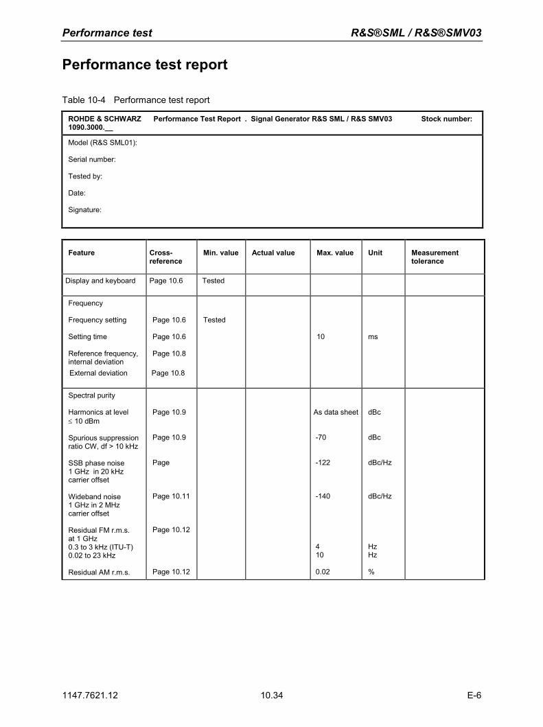
Performance test R&S®SML / R&S®SMV03
1147.7621.12 10.34 E-6
Performance test report
Table 10-4 Performance test report
ROHDE & SCHWARZ Performance Test Report . Signal Generator R&S SML / R&S SMV03 Stock number: 1090.3000.__
Model (R&S SML01): Serial number: Tested by: Date: Signature:
Feature Cross-reference
Min. value Actual value Max. value Unit Measurement tolerance
Display and keyboard Page 10.6 Tested
Frequency Frequency setting Setting time Reference frequency, internal deviation External deviation
Page 10.6 Page 10.6 Page 10.8
Page 10.8
Tested
10
ms
Spectral purity Harmonics at level ≤ 10 dBm Spurious suppression ratio CW, df > 10 kHz
SSB phase noise 1 GHz in 20 kHz carrier offset Wideband noise 1 GHz in 2 MHz carrier offset Residual FM r.m.s. at 1 GHz 0.3 to 3 kHz (ITU-T) 0.02 to 23 kHz Residual AM r.m.s.
Page 10.9
Page 10.9
Page
Page 10.11
Page 10.12
Page 10.12
As data sheet
-70
-122
-140
410
0.02
dBc
dBc
dBc/Hz
dBc/Hz
Hz Hz %
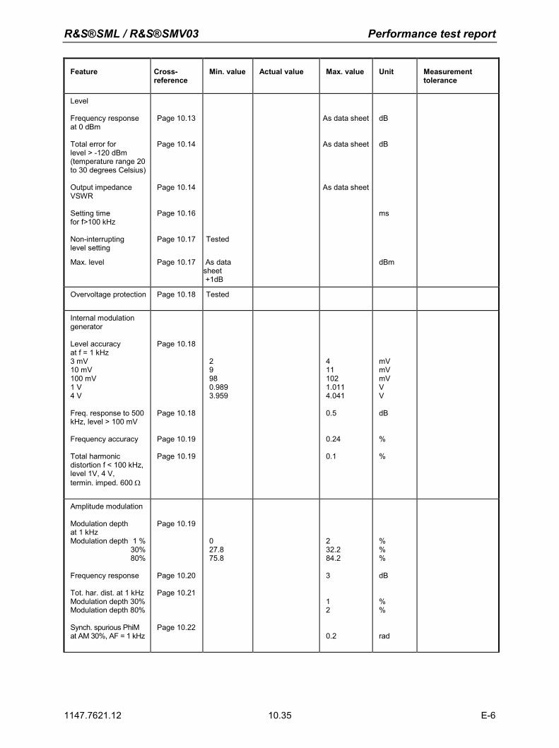
R&S®SML / R&S®SMV03 Performance test report
1147.7621.12 10.35 E-6
Feature Cross-reference
Min. value Actual value Max. value Unit Measurement tolerance
Level Frequency response at 0 dBm Total error for level > -120 dBm (temperature range 20 to 30 degrees Celsius)
Output impedance VSWR Setting time for f>100 kHz Non-interrupting level setting
Max. level
Page 10.13
Page 10.14
Page 10.14
Page 10.16
Page 10.17
Page 10.17
Tested
As data sheet +1dB
As data sheet
As data sheet
As data sheet
dB
dB
ms
dBm
Overvoltage protection Page 10.18 Tested
Internal modulation generator Level accuracy at f = 1 kHz 3 mV 10 mV 100 mV 1 V4 V
Freq. response to 500 kHz, level > 100 mV Frequency accuracy Total harmonic distortion f < 100 kHz, level 1V, 4 V, termin. imped. 600 Ω
Page 10.18
Page 10.18
Page 10.19
Page 10.19
2998 0.989 3.959
411 102 1.011 4.041 0.5
0.24 0.1
mV mV mV VV
dB
%
%
Amplitude modulation
Modulation depth at 1 kHz Modulation depth 1 %
30%80%
Frequency response Tot. har. dist. at 1 kHzModulation depth 30%Modulation depth 80%
Synch. spurious PhiM at AM 30%, AF = 1 kHz
Page 10.19
Page 10.20
Page 10.21
Page 10.22
027.8 75.8
232.2 84.2 3
12
0.2
%%%
dB
%%
rad
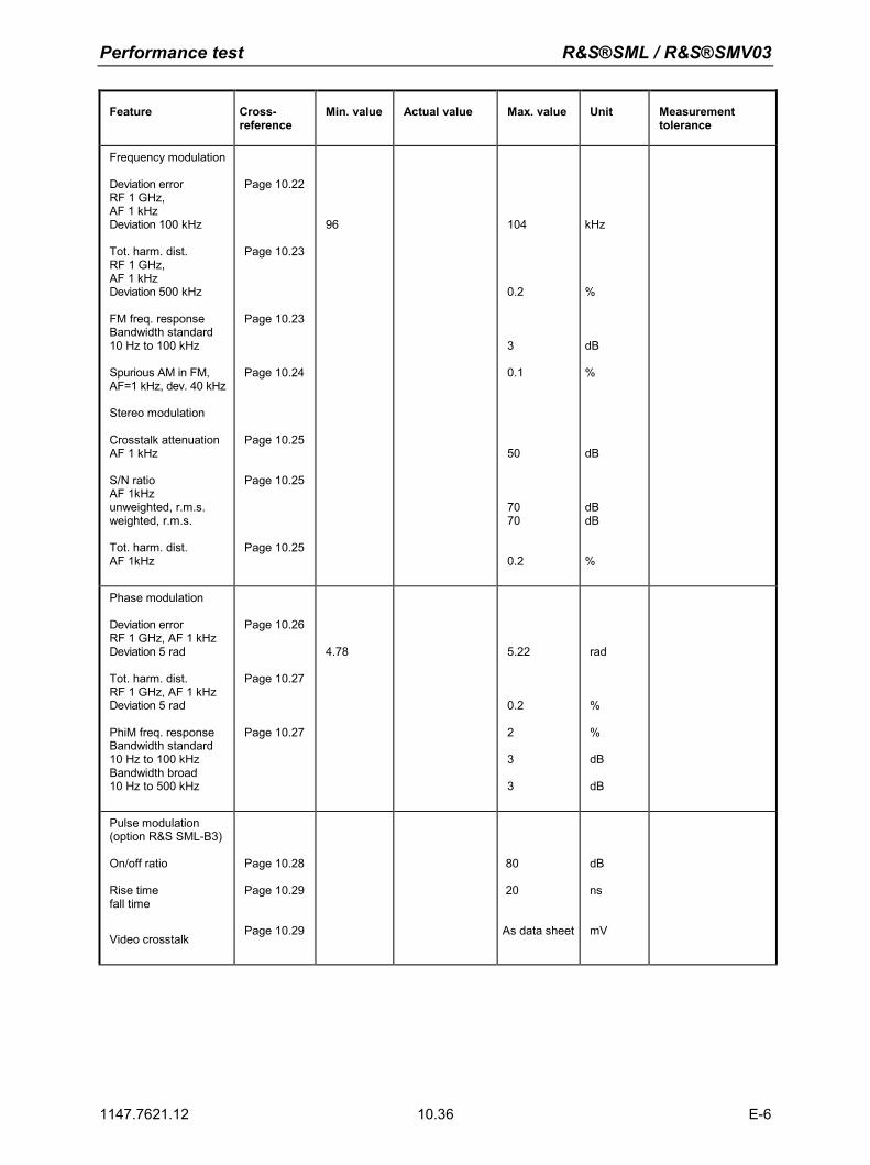
Performance test R&S®SML / R&S®SMV03
1147.7621.12 10.36 E-6
Feature Cross-reference
Min. value Actual value Max. value Unit Measurement tolerance
Frequency modulation
Deviation error RF 1 GHz, AF 1 kHz Deviation 100 kHz Tot. harm. dist. RF 1 GHz, AF 1 kHz Deviation 500 kHz FM freq. response Bandwidth standard 10 Hz to 100 kHz Spurious AM in FM, AF=1 kHz, dev. 40 kHz
Stereo modulation Crosstalk attenuation AF 1 kHz S/N ratio AF 1kHz unweighted, r.m.s. weighted, r.m.s. Tot. harm. dist. AF 1kHz
Page 10.22
Page 10.23
Page 10.23
Page 10.24
Page 10.25
Page 10.25
Page 10.25
96
104
0.2
3
0.1
50
70 70
0.2
kHz
%
dB %
dB
dB dB
%
Phase modulation Deviation error RF 1 GHz, AF 1 kHz Deviation 5 rad Tot. harm. dist. RF 1 GHz, AF 1 kHz Deviation 5 rad PhiM freq. response Bandwidth standard 10 Hz to 100 kHz Bandwidth broad 10 Hz to 500 kHz
Page 10.26
Page 10.27
Page 10.27
4.78
5.22
0.2 2
3
3
rad
%
%
dB dB
Pulse modulation (option R&S SML-B3)
On/off ratio Rise time fall time
Video crosstalk
Page 10.28
Page 10.29
Page 10.29
80 20
As data sheet
dB ns
mV
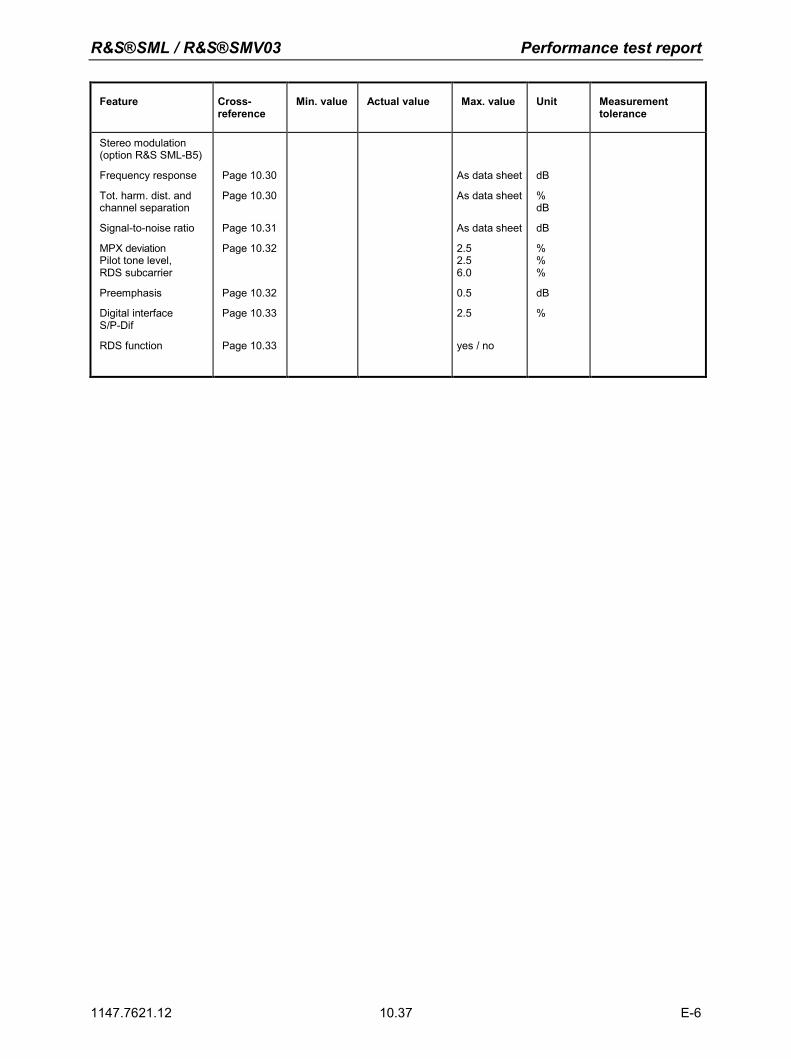
R&S®SML / R&S®SMV03 Performance test report
1147.7621.12 10.37 E-6
Feature Cross-reference
Min. value Actual value Max. value Unit Measurement tolerance
Stereo modulation (option R&S SML-B5)
Frequency response
Tot. harm. dist. and channel separation
Signal-to-noise ratio
MPX deviation Pilot tone level, RDS subcarrier
Preemphasis
Digital interface S/P-Dif
RDS function
Page 10.30
Page 10.30
Page 10.31
Page 10.32
Page 10.32
Page 10.33
Page 10.33
As data sheet
As data sheet
As data sheet
2.5 2.5 6.0
0.5
2.5
yes / no
dB
%dB
dB
%%%
dB
%
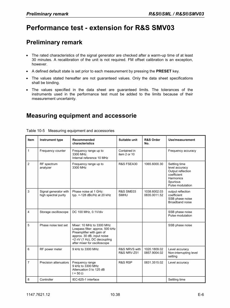
Preliminary remark R&S®SML / R&S®SMV03
1147.7621.12 10.38 E-6
Performance test - extension for R&S SMV03
Preliminary remark
• The rated characteristics of the signal generator are checked after a warm-up time of at least 30 minutes. A recalibration of the unit is not required. FM offset calibration is an exception, however.
• A defined default state is set prior to each measurement by pressing the PRESET key.
• The values stated hereafter are not guaranteed values. Only the data sheet specifications shall be binding.
• The values specified in the data sheet are guaranteed limits. The tolerances of the instruments used in the performance test must be added to the limits because of their measurement uncertainty.
Measuring equipment and accessorie
Table 10-5 Measuring equipment and accessories
Item Instrument type Recommended characteristics
Suitable unit R&S Order No.
Use/measurement
1 Frequency counter Frequency range up to 3300 MHz. Internal reference 10 MHz
Contained in item 2 or 10
Frequency accuracy
2 RF spectrum analyzer
Frequency range up to 3300 MHz
R&S FSEA30
1065.6000.30 Settling time level accuracy Output reflection coefficient Harmonics Spurious Pulse modulation
3 Signal generator with high spectral purity
Phase noise at 1 GHz: typ. <-128 dBc/Hz at 20 kHz
R&S SME03 SMHU
1038.6002.030835.0011.52
output reflection coefficient SSB phase noise Broadband noise
4 Storage oscilloscope DC 100 MHz, 0.1V/div SSB phase noise Pulse modulation
5 Phase noise test set Mixer: 10 MHz to 3300 MHz Lowpass filter: approx. 500 kHzPreamplifier with gain of approx. 30 dB, input noise <2 nV (1 Hz), DC decoupling after mixer for oscilloscope
SSB phase noise
6 RF power meter 9 kHz to 3300 MHz R&S NRVS with R&S NRV-Z51
1020.1809.020857.9004.02
Level accuracy Non-interrupting level setting
7 Precision attenuators Frequency range 9 kHz to 3300 MHz Attenuation 0 to 125 dB I = 50 Ω
R&S RSP 0831.3515.02 Level accuracy
8 Controller IEC-625-1 interface Settling time
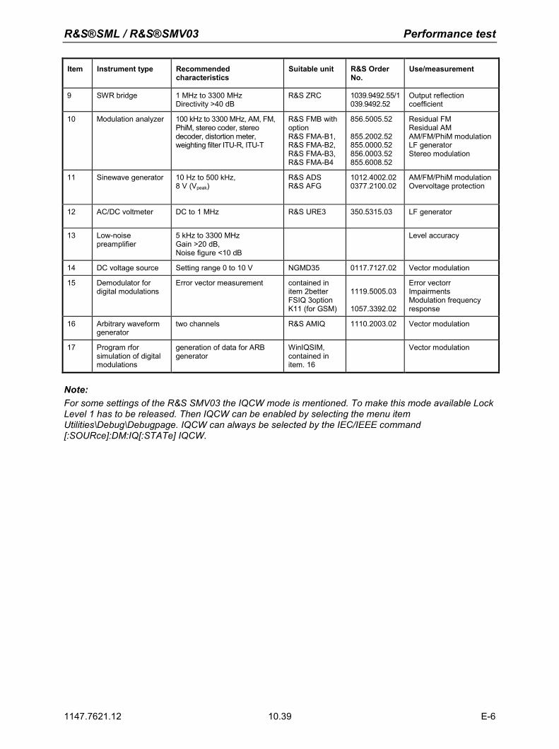
R&S®SML / R&S®SMV03 Performance test
1147.7621.12 10.39 E-6
Item Instrument type Recommended characteristics
Suitable unit R&S Order No.
Use/measurement
9 SWR bridge 1 MHz to 3300 MHz Directivity >40 dB
R&S ZRC 1039.9492.55/1039.9492.52
Output reflection coefficient
10 Modulation analyzer 100 kHz to 3300 MHz, AM, FM, PhiM, stereo coder, stereo decoder, distortion meter, weighting filter ITU-R, ITU-T
R&S FMB with option R&S FMA-B1, R&S FMA-B2, R&S FMA-B3, R&S FMA-B4
856.5005.52 855.2002.52 855.0000.52 856.0003.52 855.6008.52
Residual FM Residual AM AM/FM/PhiM modulationLF generator Stereo modulation
11 Sinewave generator 10 Hz to 500 kHz, 8 V (Vpeak)
R&S ADS R&S AFG
1012.4002.020377.2100.02
AM/FM/PhiM modulation Overvoltage protection
12 AC/DC voltmeter
DC to 1 MHz R&S URE3 350.5315.03 LF generator
13 Low-noise preamplifier
5 kHz to 3300 MHz Gain >20 dB, Noise figure <10 dB
Level accuracy
14 DC voltage source Setting range 0 to 10 V NGMD35 0117.7127.02 Vector modulation
15 Demodulator for digital modulations
Error vector measurement contained in item 2better FSIQ 3option K11 (for GSM)
1119.5005.03
1057.3392.02
Error vectorr Impairments Modulation frequency response
16 Arbitrary waveform generator
two channels R&S AMIQ 1110.2003.02 Vector modulation
17 Program rfor simulation of digital modulations
generation of data for ARB generator
WinIQSIM, contained in item. 16
Vector modulation
Note: For some settings of the R&S SMV03 the IQCW mode is mentioned. To make this mode available Lock Level 1 has to be released. Then IQCW can be enabled by selecting the menu item Utilities\Debug\Debugpage. IQCW can always be selected by the IEC/IEEE command [:SOURce]:DM:IQ[:STATe] IQCW.
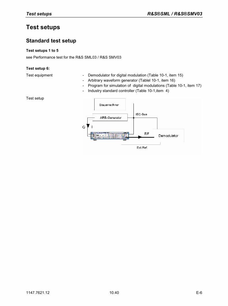
Test setups R&S®SML / R&S®SMV03
1147.7621.12 10.40 E-6
Test setups
Standard test setup Test setups 1 to 5
see Performance test for the R&S SML03 / R&S SMV03
Test setup 6:
Test equipment - Demodulator for digital modulation (Table 10-1, item 15) - Arbitrary waveform generator (Tablel 10-1, item 16) - Program for simulation of digital modulations (Table 10-1, item 17) - Industry standard controller (Table 10-1,item 4)
Test setup
R&S®SML / R&S®SMV03 Test sequence
1147.7621.12 10.41 E-6
Test sequence
Settig time
Test setup Test setup 2 (performance test R&S SML03 / R&S SMV03)
Test method See Performance test R&S SML03 / R&S SMV03.
Vorbereiten der Messung
See Performance test R&S SML03 / R&S SMV03.
Settings on R&S SMV03
- LEVEL 0 dBm - ALC TABLE - VECTORMOD STATE IQCW - UTILITIES REF OSC SOURCE EXTERNAL
Measurement See Performance test R&S SML03 / R&S SMV03.
The following settings are to be measured in both directions: Start frequencies Target frequencies 100 MHz 250.0000001 MHz 250 MHz 1170 MHz 1900 MHz 3300 MHz
Spectral purity
Harmonic suppression
Test setup Test setup 1 with spectrum analyzer (see Performance test R&S SML03 / R&S SMV03)
Settings on SMV - VECTORMOD STATE IQCW
- LEVEL 8 dBm (or max. level according to datasheet) - FREQ test frequency of harmonics - Test frequency of harmonics: 5 MHz, 76 MHz, 100 MHz, 151 MHz,
200 MHz, 255 MHz, 400 MHz, 605 MHz, 700 MHz, 900 MHz, fmax, 1211 MHz,1500 MHz, 1700 MHz, 2200 MHz, 3000 MHz, 3300 MHz
Settings with option B3 - Test frequencies harmonics > 20 MHz
Setting on spectrum analyzer - Reference level pegel = test level + 10 dB, 10 dB/div
- Span 300 kHz, resolution 30 kHz
Measurement See Performance test R&S SML03 / R&S SMV03.
Evaluation See Performance test R&S SML03 / R&S SMV03.
Test sequence R&S®SML / R&S®SMV03
1147.7621.12 10.42 E-6
Nonharmonic suppression
Test setup Test setup 1 with spectrum analyzer (see Performance test R&S SML03 / R&S SMV03)
Settings on R&S SMV03
- UTILITIES REF OSC SOURCE EXTERNAL - LEVEL 10 dBm - VECTORMOD STATE IQCW - FREQ Test frequecy of nonharmonics Test frequencies of
nonharmonics: 250.0MHz, 250.0000001MHz
Setting on spectrum analyzer - Reference level = test level + 3 dB, 10 dB/div - Test frequency = 200 MHz, 800 MHz, 1600 MHz, 2400 MHz, 3200
MHz - Span = 1 MHz - Switch on average: 5 samples
Measurement See Performance test R&S SML03 / R&S SMV03.
Evaluation See Performance test R&S SML03 / R&S SMV03.
Broadband noise
Test setup Test setup 3 (see Performance test R&S SML03 / R&S SMV03)
Settings on R&S SMV03
- UTILITIES REF OSC SOURCE EXTERNAL - VECTORMOD STATE IQCW - LEVEL 0 dBm (or . level according to mixer specification) - FREQUENCY 1 GHz (or any test frequency)
Test method See Performance test R&S SML03 / R&S SMV03.
Measurement See Performance test R&S SML03 / R&S SMV03 Evaluation See Performance test R&S SML03 / R&S SMV03.
R&S®SML / R&S®SMV03 Test sequence
1147.7621.12 10.43 E-6
Level
Level frequency response and linearity
Test method for level in measurement range of power meter (up to approx. - 22 dBm) Test equipment See Performance test R&S SML03 / R&S SMV03. Test setup See Performance test R&S SML03 / R&S SMV03.
Settings on R&S SMV03
- VECTORMOD STATE IQCW - FREQ Test frequency level accuracy - Test frequencies: 5 MHz, 5,1 MHz, 76 MHz, 77 MHz, 151 MHz,
255 MHz, 302 MHz, 605 MHz, 606 MHz, 725 MHz, 970 MHz, fmax,1210.5 MHz, 1211 MHz, 1818 MHz, 2000 MHz, 2200 MHz, 2800 MHz, 3000 MHz, 3300 MHz
- LEVEL Test level 1 level accuracy - Test level 1: 8 dBm, 3.1 dBm, 3 dBm, -2 dBm, -7 dBm,
-12 dBm, -17 dBm, -21.9 dBm, -22.0 dBm
Settings on powermeter See Performance test R&S SML03 / R&S SMV03 Measurement See Performance test R&S SML03 / R&S SMV03. Measurement procedure for low levels (>-115 dBm)
Caution: The precondition for correct measurement is that the used components are wholly RF-shielded.
Test Method see Performance test R&S SML03 / R&S SMV03. Settings on R&S SMV03 - VECTORMOD STATE IQCW
- Test frequencies >=5MHz
Setting time
Test setup Test setup 2 (see Performance test R&S SML03 / R&S SMV03)
Test method See Performance test R&S SML03 / R&S SMV03
Preparing measurement See Performance test R&S SML03 / R&S SMV03
Settings on R&S SMV03 - VECTORMOD STATE IQCW - FREQ Test frequency setting time
MeasurementMessung See Performance test R&S SML03 / R&S SMV03
Non-interrupting level setting (ATTENUATOR FIXED)
Tset setup Test setup 1 with spectrum analyzer (Performance test R&S SML03 / R&S SMV03)
Settings on R&S SMV03 - VECTORMOD STATE IQCW - FREQ Test frequencies ATT-FIX - Test frequencies: 100 kHz, 5,1 MHz, fmax, 1211 MHz.
2200 MHz, 3300 MHz - LEVEL 3.1 dBm - LEVEL LEVEL ATTENUATOR MODE FIXED
Measurement See Performance test R&S SML03 / R&S SMV03
Test sequence R&S®SML / R&S®SMV03
1147.7621.12 10.44 E-6
Vector modulation
Input impedance (VSWR)
Test equipment Test setup for output reflection factor (Performance test R&S SML03 / R&S SMV03)
Test setup The test port of the bridge is connected to the I or Q input instead
of the RF output.
Measurement Settings on R&S SMV03 Level 0 dBm. Carrier frequency 900 MHz. Vector modulation on .
Settings on signal generator Level 10 dBm. Carrier frequency 5, 10 and 30 MHz.
Screw the VSWR bridge off and measure the level as reference level.
Connect the test port of the VSWR bridge to I input and measure the level again. The voltage ratio of test level to reference level is the input reflection coefficient r of the I input.
From this, the voltage standing wave ratio (VSWR) can be calculated as follows: VSWR = (1+r)/(1-r)
Repeat the measurement for the Q input.
Maximum level
Test equipment Power meter (Table 5-1, item 8). DC voltage source (Table 5-1, item 12).
Test setup Connect the power meter (Table 5-1, item 8) to the RF output. Connect DC voltage source to the I or Q input.
Measurement Settings on R&S SMV03 Level 0 dBm. Carrier frequency 900 MHz.
Measure level without modulation as reference level.
SelectSTATE IQ in the menu Vector Mod. Set DC voltage source to 0.500 V. Measure the level again . The diffrence between the levels should be within permissible tolerance specified in the data sheet.
R&S®SML / R&S®SMV03 Test sequence
1147.7621.12 10.45 E-6
Error vector
Test set Test setup 6 vector modulation.
Measurement Instead of static measurement an equivalent dynamic measurement with a low symbol rate is carried out. Settings on R&S SMV03
Level 0 dBm Select State IQ in the menu Vector Mod M.
Generate a modulation signal on the ARB generator using the controller and the simulation program: Modulation 16QAM no coding SQR COS-Filter with α = 0.5 PRBS9 data sequence Pulse width and oversampling 32 Length 100 symbols Symbol clock 10 kHz.
Check if the channels on the ARB generator are equal and adjust if necessary.
Make the corresponding settings on the demodulator. Synchronize to abit sequence, starting with the 9th symbol, 12 bits long, result length 80 symbols.
Vary the carrier frequency from 5 MHz to RFmax . For recommended setting values see Table 5-2 at least , *-frequencies.
Measure the error vector magnitude (peak and rms) on the demodulator.
Modulation frequency response
Test equipment Spectrum analyzer (Table 10-5, item 2) signal generator (Table 10-5, item 5).
Test setup Connect the Rf output of the R&S SMV03 to the spectrum analyzer, connect the signal generator to the I input of R&S SMV03.
Test method By applying a sinewave AC voltage to the I (or Q) input, an amplitude modulation with a suppressed carrier is generated. The modualtion frequency response is determined by measuring the sidebands as a function of the frequency of the applied AC voltage.
Measurement Settings on R&S SMV03 Test level pegel 0 dBm, test frequency > 30.3 MHz Select State IQ in the menu Vector Mod.
Settings on signal generator level Pegel 0.5 V (Vpeak) corresponding to 4 dBm.
Settings on analyzer Center frequency = test frequency, Span 30 kHz, RBW 10 kHz, Reference level = test level + 6 dB Scale 2 dB/div.
Test sequence R&S®SML / R&S®SMV03
1147.7621.12 10.46 E-6
Vary the frequency from 1 MHz to 30 MHz on the signal generator and measure the modulation sidebands on the analyzer (CENTER FREQ. = test frequency + modulation frequency). The result level for a sideband frequency is the average value of the left and the right sideband level.
For evaluation, determine the difference between the highest and the lowest sideband. The modulation frequency response is the difference between the highest and the lowest sideband. .
Residual carrier and leakage
Test equipment Spectrum analyzer (Table 5-1, item 2).
Test setup Connect the spectrum analyzer to the RF output of the R&S SMV03.
Measurement Settings on R&S SMV03 Test level Pvmmax,Test frequencies 395, 600, 936, 1250, 1801, (2200), 3301, 5099, 5501, (4400), 6400 MHz, unmodulated Select State Off inthe menu Vector Mod Settings on analyzer Center frequency = test frequency , Span 1 MHz, Reference level = test level Scale 10 dB/div.
First measuere the unmodulated level as a reference.
Then switch on vector modulation with open inputs (State IQ) and measure the residual carrier. The residual carrier in dBc is the level of the residual signal found reffered to the output signal of the DUT without modulation (dBc = reffered to he carrier
Set Impairment State On and Leakage 10% on the SMV=3 The residual carrier should increase 10% (-20 dBc).
R&S®SML / R&S®SMV03 Test sequence
1147.7621.12 10.47 E-6
I/Q Imbalance
Measurement of Imbalance
Test equipment Spectrum analyzer (Table 5-1, item 2) Adjustable DC voltage source (Table 5-1, item 12).
Test setup Connect the spectrum analyzer to the RF output of the R&S SMV03. Connect the DC voltage source to the I or the Q input.
Measurement Settings on the R&S SMV03 Test frequencies: 250MHz, 250MHz+0.1Hz, 420MHz, 420MHz+0.1Hz, 665MHz, 900 MHz, 1170MHz, 1900MHz, 3000MHz Test level 0 dBm Select State IQ in the menu vector Mod.
Settings on analyzer Center frequency = test frequency., Span 1 MHz Reference level = test level +3 dB Scale 1 dB/div.
First measure the undistorted level as a reference. To this end, apply a DC voltage of 0.500 V to the I and then to the Q and note down the corresponding RF levels as reference levels. In the menu Vector Mod/Impairment State select On and Imbalance 10 %. repeat the Level measurement. The I level should increase by the set imbalance, the Q level decrease by the inverse ratio. With 10 %, the I level should increase to 1.1 times, the Q level should be reduced to 0.909 times the original value (corresponding to ±0.83 dB).
Test sequence R&S®SML / R&S®SMV03
1147.7621.12 10.48 E-6
Measurement quadrature
Test setup Test setup 6 vector modulation.
Measurement Settings on R&S SMV03 Level 0 dBm Test frequence see measurement of imbalance In the menu Vector Mod, select State IQ, Impairment State Off, Quadrature Error 10.
Generate a modulation signal using the controller and the simulation program: Modulation 16QAM No coding SQR COS-Filter with α = 0.5 PRBS9 data sequence Pulse width and oversampling 32 Length 100 symbols Symbolclock 10 kHz.
Make the corresponding settings on the demodulator. Synchronize to a bit sequence, satrting with the 9th symbol, 12 bits long, result lenght 80 symbols.
Attention: The mappings of the DUT and the demodulator have to correspond! Select the vector representation on the demodulator.
The symbols should be located in a square grid. Select Impairment State On on the R&S SMV03.
The symbols must no longer be arranged at right angles; the Y axis should be inclined towards the left by 10 °, with a setting of - 10 ° it should be inclined towards the right.
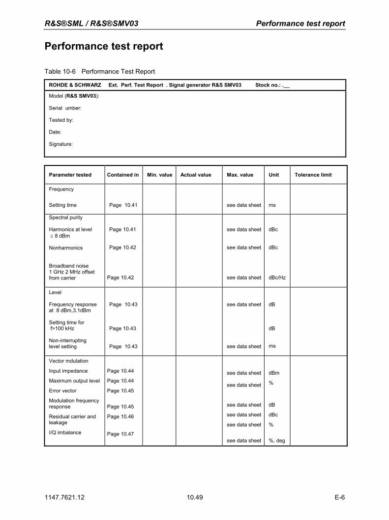
R&S®SML / R&S®SMV03 Performance test report
1147.7621.12 10.49 E-6
Performance test report
Table 10-6 Performance Test Report
ROHDE & SCHWARZ Ext. Perf. Test Report . Signal generator R&S SMV03 Stock no.: .__
Model (R&S SMV03): Serial umber: Tested by: Date: Signature:
Parameter tested Contained in Min. value Actual value Max. value Unit Tolerance limit
Frequency
Setting time
Page 10.41
see data sheet
ms
Spectral purity Harmonics at level ≤ 8 dBm Nonharmonics
Broadband noise 1 GHz 2 MHz offset from carrier
Page 10.41
Page 10.42
Page 10.42
see data sheet
see data sheet
see data sheet
dBc
dBc
dBc/Hz
Level Frequency response at 8 dBm,3.1dBm Setting time for f>100 kHz Non-interrupting level setting
Page 10.43
Page 10.43
Page 10.43
see data sheet
see data sheet
dB
dB
ms
Vector mdulation
Input impedance
Maximum output level
Error vector
Modulation frequency response
Residual carrier and leakage
I/Q imbalance
Page 10.44
Page 10.44
Page 10.45
Page 10.45
Page 10.46
Page 10.47
see data sheet
see data sheet
see data sheet
see data sheet
see data sheet
see data sheet
dBm
%
dB
dBc
%
%, deg