Embed Size (px)
Citation preview
Ching-Yuan Yang
National Chung-Hsing UniversityDepartment of Electrical Engineering
Signal Generators and Waveform-Shaping Circuits
Microelectronic Circuits
13-1 Ching-Yuan Yang / EE, NCHUMicroelectrics (III)
Outline
Basic Principles of Sinusoidal Oscillators
Op Amp-RC Oscillator Circuits
LC and Crystal Oscillators
Bistable Multivibrators
Generation of Square and Triangular Waveforms Using Astable
Multivibrators
Generation of a Standardized Pulse – The Monostable Multivibrator
Integrated-Circuit Timers
13-2 Ching-Yuan Yang / EE, NCHUMicroelectrics (III)
Basic Principles of Sinusoidal Oscillators
13-3 Ching-Yuan Yang / EE, NCHUMicroelectrics (III)
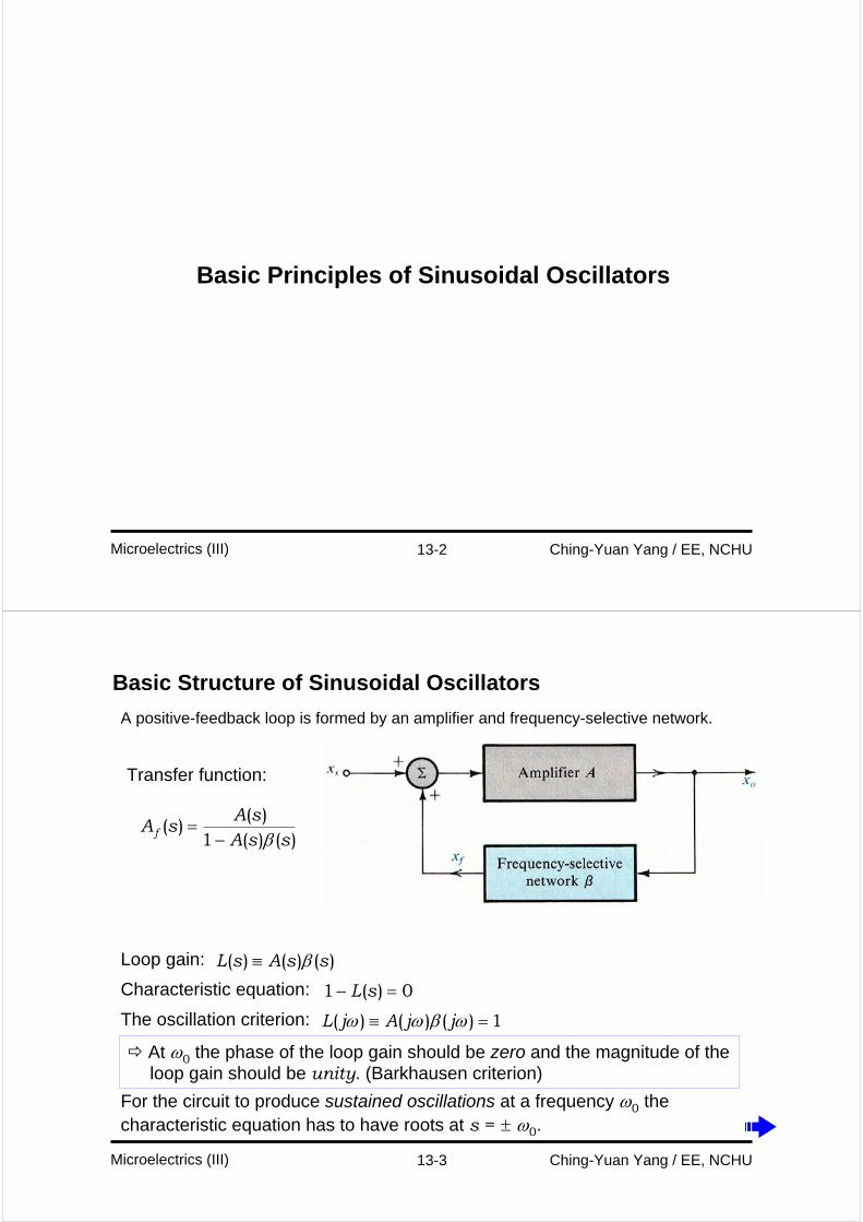
Basic Structure of Sinusoidal Oscillators
Loop gain: )()()( ssAsL β≡
Characteristic equation: 0)(1 =− sL
The oscillation criterion: 1)()()( =≡ ωβωω jjAjL
At ω0 the phase of the loop gain should be zero and the magnitude of the loop gain should be unity. (Barkhausen criterion)
For the circuit to produce sustained oscillations at a frequency ω0 the characteristic equation has to have roots at s = ± ω0.
A positive-feedback loop is formed by an amplifier and frequency-selective network.
Transfer function:
)()(1)(
)(ssA
sAsAf β−
=
13-4 Ching-Yuan Yang / EE, NCHUMicroelectrics (III)
In an actual oscillator circuit, no input signal is present (xs = 0):
the feedback signal xf = βxo should be sufficiently large so that when multiplied by A it produces xo , Axf = xo , that is
Aβxo = xo Aβ = 1
At ω0, the phase of the loop should be zero and the magnitude of the loop gain should be
unity.
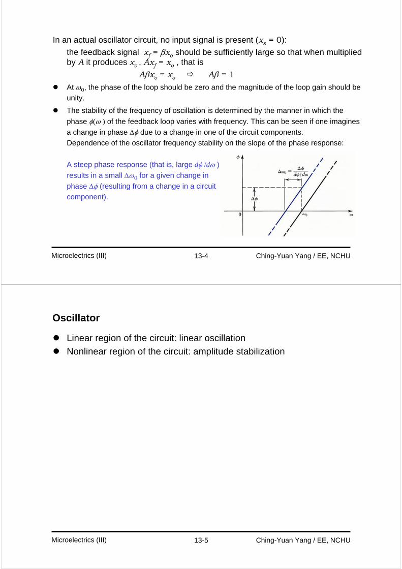
The stability of the frequency of oscillation is determined by the manner in which the
phase φ(ω ) of the feedback loop varies with frequency. This can be seen if one imagines
a change in phase Δφ due to a change in one of the circuit components.
Dependence of the oscillator frequency stability on the slope of the phase response:
A steep phase response (that is, large dφ /dω )
results in a small Δω0 for a given change in
phase Δφ (resulting from a change in a circuit
component).
13-5 Ching-Yuan Yang / EE, NCHUMicroelectrics (III)
Oscillator
Linear region of the circuit: linear oscillation
Nonlinear region of the circuit: amplitude stabilization
13-6 Ching-Yuan Yang / EE, NCHUMicroelectrics (III)
Nonlinear Amplitude Control
The oscillation condition – the Barkhausen criterion:
Aβ = 1 at ω = ω0
However, the temperature changes and Aβ becomes slightly less than unity.
Oscillation will cease in this case.
In order to ensure oscillation in the presence of temperature and process variations, we typically choose the loop gain to be at least twice or three times the required value.
If Aβ exceeds unity, oscillations will grow in amplitude. We therefore need a mechanism for forcing Aβ to remain equal to unity at the desired value of output amplitude.
This task is accomplished by providing a nonlinear circuit for gain control.
Gain-control mechanism:
To ensure that oscillations will start, Aβ is slightly greater than unity.
Sustain oscillations at the desired amplitude.
13-7 Ching-Yuan Yang / EE, NCHUMicroelectrics (III)
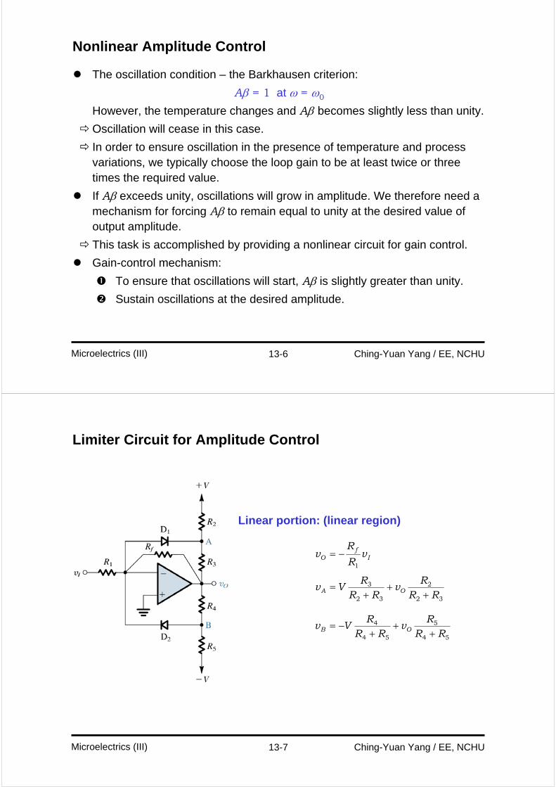
Limiter Circuit for Amplitude Control
Linear portion: (linear region)
If
O vR
Rv
1
−=
32
2
32
3
RRR
vRR
RVv OA +
++
=
54
5
54
4
RRR
vRR
RVv OB +
++
−=
13-8 Ching-Yuan Yang / EE, NCHUMicroelectrics (III)
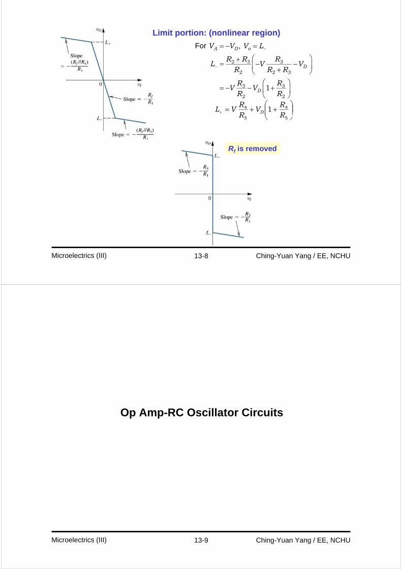
Limit portion: (nonlinear region)
For , A D o
D
D
V V V L
R R RL V V
R R R
R RV V
R R
−
−
= − =
⎛ ⎞+= − −⎜ ⎟+⎝ ⎠
⎛ ⎞= − − +⎜ ⎟
⎝ ⎠
2 3 3
2 2 3
3 3
2 2
1
⎟⎟⎠
⎞⎜⎜⎝
⎛++=+
5
4
5
4 1RR
VRR
VL D
Rf is removed
13-9 Ching-Yuan Yang / EE, NCHUMicroelectrics (III)
Op Amp-RC Oscillator Circuits
13-10 Ching-Yuan Yang / EE, NCHUMicroelectrics (III)
Wien-Bridge Oscillator
Wien-bridge oscillator without amplitude stabilization
sCRsCR
RR
ZZ
Z
RR
sLsp
p
13
11)( 1
2
1
2
++
+=
+⎟⎟⎠
⎞⎜⎜⎝
⎛+=
⎟⎠⎞
⎜⎝⎛ −+
+=
CRCRj
RR
jL
ωω
ω1
3
1)( 1
2
Oscillation
(phase = 0, |L(jω)| = 1)
2 1
1
20 ==
RR
CRω
13-11 Ching-Yuan Yang / EE, NCHUMicroelectrics (III)
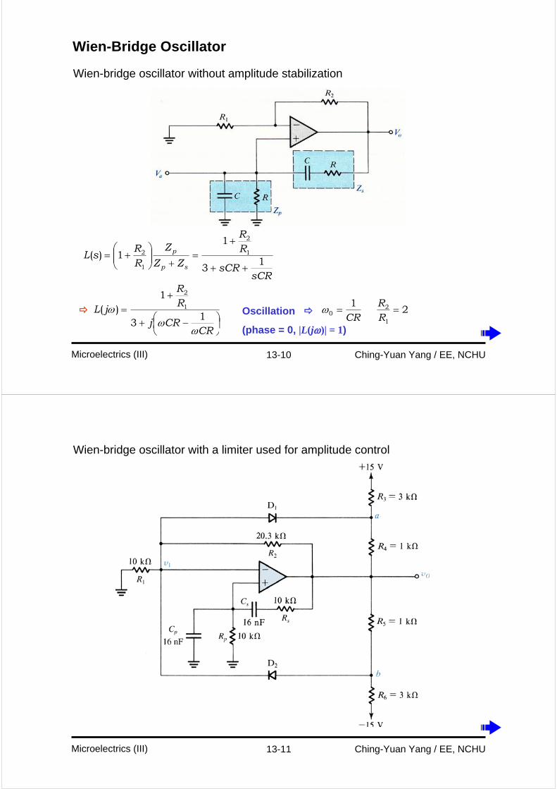
Wien-bridge oscillator with a limiter used for amplitude control
13-12 Ching-Yuan Yang / EE, NCHUMicroelectrics (III)
Wien-bridge oscillator with an alternative method for amplitude stabilization
13-13 Ching-Yuan Yang / EE, NCHUMicroelectrics (III)
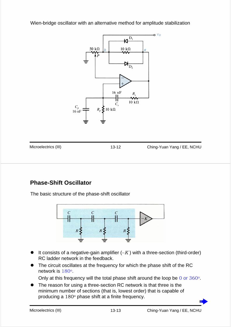
Phase-Shift Oscillator
The basic structure of the phase-shift oscillator
It consists of a negative-gain amplifier (−K ) with a three-section (third-order) RC ladder network in the feedback.
The circuit oscillates at the frequency for which the phase shift of the RC network is 180o.
Only at this frequency will the total phase shift around the loop be 0 or 360o.
The reason for using a three-section RC network is that three is the minimum number of sections (that is, lowest order) that is capable of producing a 180o phase shift at a finite frequency.
13-14 Ching-Yuan Yang / EE, NCHUMicroelectrics (III)
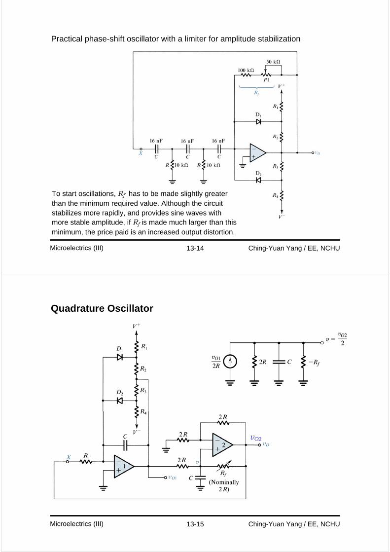
Practical phase-shift oscillator with a limiter for amplitude stabilization
To start oscillations, Rf has to be made slightly greater than the minimum required value. Although the circuit stabilizes more rapidly, and provides sine waves with more stable amplitude, if Rf is made much larger than this minimum, the price paid is an increased output distortion.
13-15 Ching-Yuan Yang / EE, NCHUMicroelectrics (III)
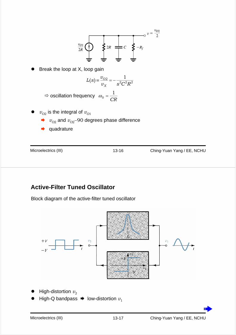
Quadrature Oscillator
vO2
13-16 Ching-Yuan Yang / EE, NCHUMicroelectrics (III)
Break the loop at X, loop gain
vO2 is the integral of vO1
vO2 and vO2−90 degrees phase difference
quadrature
( ) O
X
vL s
v s C R≡ = −2
2 2 21
oscillation frequencyCR1
0 =ω
13-17 Ching-Yuan Yang / EE, NCHUMicroelectrics (III)
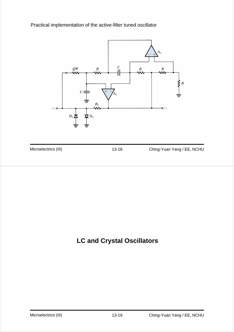
Active-Filter Tuned Oscillator
Block diagram of the active-filter tuned oscillator
High-distortion v2
High-Q bandpass low-distortion v1
13-18 Ching-Yuan Yang / EE, NCHUMicroelectrics (III)
Practical implementation of the active-filter tuned oscillator
13-19 Ching-Yuan Yang / EE, NCHUMicroelectrics (III)
LC and Crystal Oscillators
13-20 Ching-Yuan Yang / EE, NCHUMicroelectrics (III)
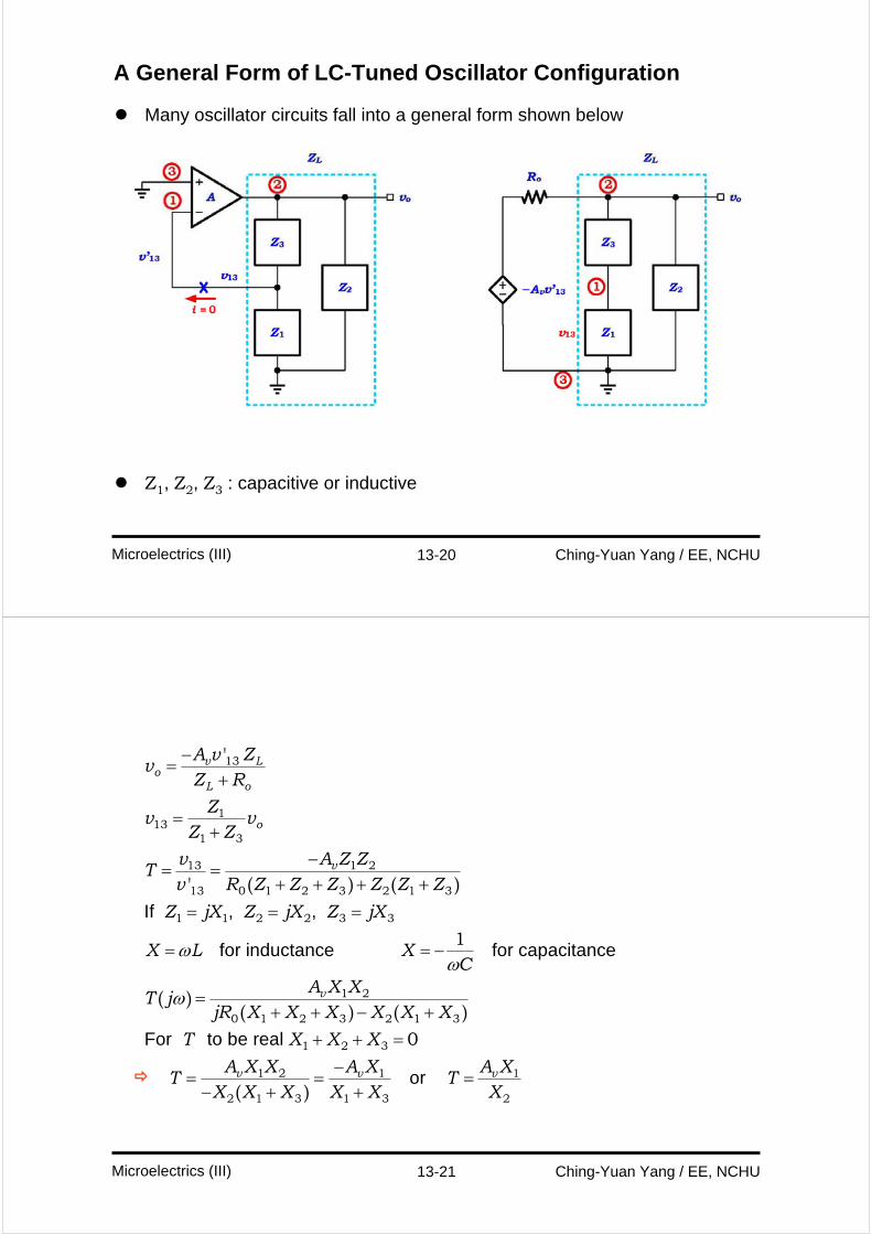
A General Form of LC-Tuned Oscillator Configuration
Many oscillator circuits fall into a general form shown below
Z1, Z2, Z3 : capacitive or inductive
13-21 Ching-Yuan Yang / EE, NCHUMicroelectrics (III)
If , ,
for inductance for capacitance
For to
'
' ( ) ( )
( )( ) ( )
v Lo
L o
o
v
v
A v Zv
Z R
Zv v
Z Z
A Z ZvT
v R Z Z Z Z Z Z
Z jX Z jX Z jX
X L XC
A X XT j
jR X X X X X X
T
ωω
ω
−=
+
=+
−= =
+ + + += = =
= = −
=+ + − +
13
113
1 3
1 213
13 0 1 2 3 2 1 3
1 1 2 2 3 3
1 2
0 1 2 3 2 1 3
1
be real
or ( )v v v
X X X
A X X A X A XT T
X X X X X X
+ + =−
= = =− + +
1 2 3
1 2 1 1
2 1 3 1 3 2
0
13-22 Ching-Yuan Yang / EE, NCHUMicroelectrics (III)
With oscillation
|T| = 1 and ∠T = 0, 360, 720, … degrees.
i.e., T = 1
So, X1 & X2 must have the same sign (Av is positive)
X1 & X2 are L, X3 = −(X1 + X2) is C
or X1 & X2 are C, X3 = −(X1 + X2) is L.
Transistor oscillators
Collpitts oscillator
X1 & X2 are CS, X3 is L.
(feedback is achieved by using a capacitive divider)
Hartley oscillator
X1 & X2 are LS, X3 is C.
(feedback is achieved by using an inductive divider)
or ( )X L XC
ωω
= = −1
13-23 Ching-Yuan Yang / EE, NCHUMicroelectrics (III)
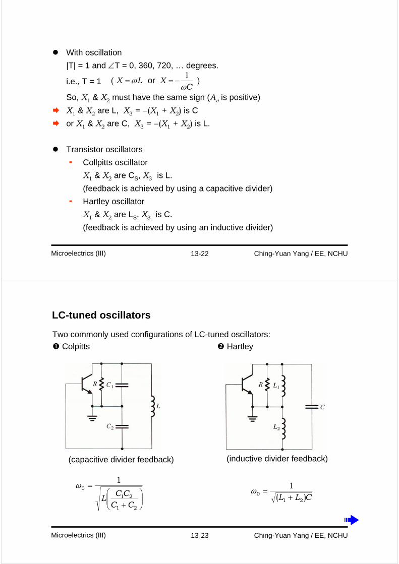
LC-tuned oscillators
Two commonly used configurations of LC-tuned oscillators:
Colpitts Hartley
⎟⎟⎠
⎞⎜⎜⎝
⎛+
=
21
21
01
CCCC
L
ωCLL )(
1
210 +=ω
(capacitive divider feedback) (inductive divider feedback)
13-24 Ching-Yuan Yang / EE, NCHUMicroelectrics (III)
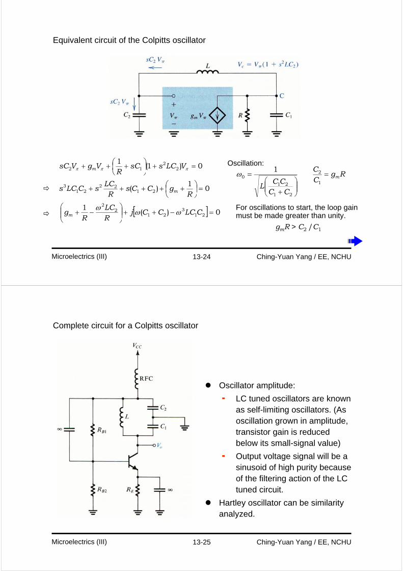
Equivalent circuit of the Colpitts oscillator
0)1(1
22
12 =+⎟⎠⎞
⎜⎝⎛ +++ πππ VLCssCR
VgVsC m
01
)( 2122
213 =⎟
⎠⎞
⎜⎝⎛ +++++
RgCCs
RLC
sCLCs m
[ ] 0)(1
213
212
2
=−++⎟⎟⎠
⎞⎜⎜⎝
⎛−+ CLCCCj
RLC
Rgm ωωω
Oscillation:
RgCC
m=1
2
⎟⎟⎠
⎞⎜⎜⎝
⎛+
=
21
21
01
CCCC
L
ω
For oscillations to start, the loop gain must be made greater than unity.
gmR > C2 /C1
13-25 Ching-Yuan Yang / EE, NCHUMicroelectrics (III)
Complete circuit for a Colpitts oscillator
Oscillator amplitude:
LC tuned oscillators are known as self-limiting oscillators. (As oscillation grown in amplitude, transistor gain is reduced below its small-signal value)
Output voltage signal will be a sinusoid of high purity because of the filtering action of the LC tuned circuit.
Hartley oscillator can be similarity analyzed.
13-26 Ching-Yuan Yang / EE, NCHUMicroelectrics (III)
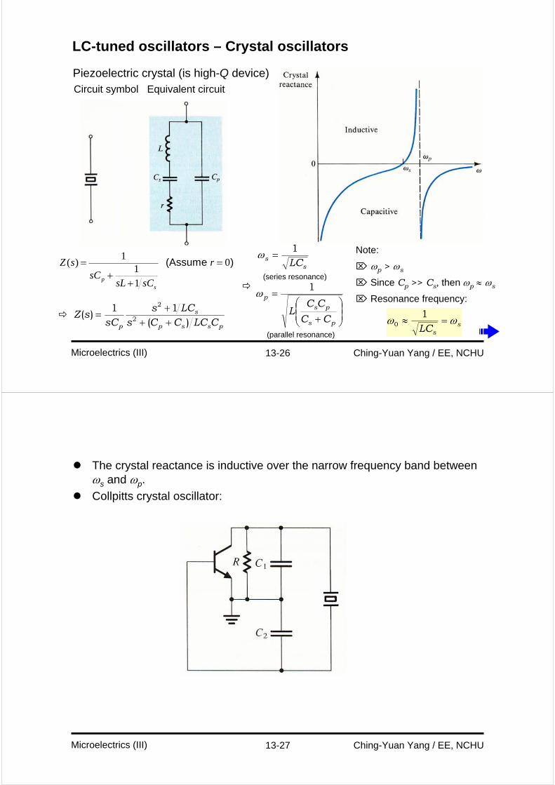
LC-tuned oscillators – Crystal oscillators
Piezoelectric crystal (is high-Q device)Circuit symbol Equivalent circuit
1( ) 0
11
(Assume )
ps
Z s rsC
sL sC
= =+
+
pssp
s
p CLCCCsLCs
sCsZ
)(11
)( 2
2
+++
=
ss LC
1=ω
⎟⎟⎠
⎞⎜⎜⎝
⎛
+
=
ps
ps
p
CC
CCL
1ω
(series resonance)
(parallel resonance)
Note:
⌦ ωp > ωs
⌦ Since Cp >> Cs, then ωp ≈ ωs
⌦ Resonance frequency:
ssLC
ωω =≈1
0
13-27 Ching-Yuan Yang / EE, NCHUMicroelectrics (III)
The crystal reactance is inductive over the narrow frequency band between ωs and ωp.
Collpitts crystal oscillator:
13-28 Ching-Yuan Yang / EE, NCHUMicroelectrics (III)
Equivalent circuit:
Crystal oscillator circuit
s p
ss
C C C C
LCω ω
<<
≈ =
, ,1 2
01
crystal
===
Z C
Z C
Z
1 2
2 1
3
13-29 Ching-Yuan Yang / EE, NCHUMicroelectrics (III)
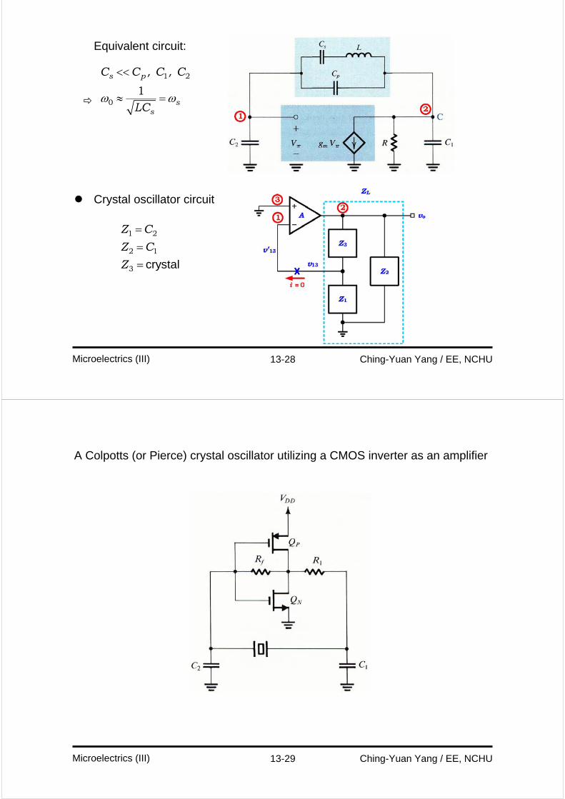
A Colpotts (or Pierce) crystal oscillator utilizing a CMOS inverter as an amplifier
13-30 Ching-Yuan Yang / EE, NCHUMicroelectrics (III)
Bistable Multivibrators
13-31 Ching-Yuan Yang / EE, NCHUMicroelectrics (III)
Bistable Multivibrators
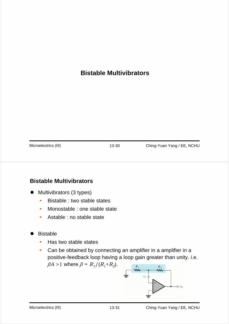
Multivibrators (3 types)
Bistable : two stable states
Monostable : one stable state
Astable : no stable state
Bistable
Has two stable states
Can be obtained by connecting an amplifier in a amplifier in a positive-feedback loop having a loop gain greater than unity. i.e. βA >1 where β = R1/(R1+R2).
13-32 Ching-Yuan Yang / EE, NCHUMicroelectrics (III)
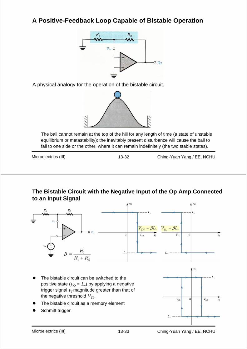
A Positive-Feedback Loop Capable of Bistable Operation
A physical analogy for the operation of the bistable circuit.
The ball cannot remain at the top of the hill for any length of time (a state of unstable equilibrium or metastability); the inevitably present disturbance will cause the ball to fall to one side or the other, where it can remain indefinitely (the two stable states).
13-33 Ching-Yuan Yang / EE, NCHUMicroelectrics (III)
The Bistable Circuit with the Negative Input of the Op Amp Connected to an Input Signal
The bistable circuit can be switched to the positive state (vO = L+) by applying a negative trigger signal vI magnitude greater than that of the negative threshold VTL.
The bistable circuit as a memory element
Schmitt trigger
+= LVTH β −= LVTL β
21
1
RRR+
=β
13-34 Ching-Yuan Yang / EE, NCHUMicroelectrics (III)
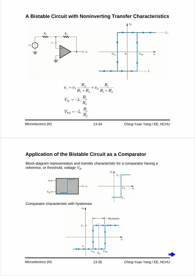
A Bistable Circuit with Noninverting Transfer Characteristics
21
1
21
2
RRR
vRR
Rvv OI +
++
=+
2
1
2
1
RR
LV
RR
LV
TH
TL
−
+
−=
−=
13-35 Ching-Yuan Yang / EE, NCHUMicroelectrics (III)
Application of the Bistable Circuit as a Comparator
Block-diagram representation and transfer characteristic for a comparator having a reference, or threshold, voltage VR.
Comparator characteristic with hysteresis
13-36 Ching-Yuan Yang / EE, NCHUMicroelectrics (III)
Illustrating the use of hysteresis in the comparator characteristics as a means of rejecting interference
Can reject interference
13-37 Ching-Yuan Yang / EE, NCHUMicroelectrics (III)
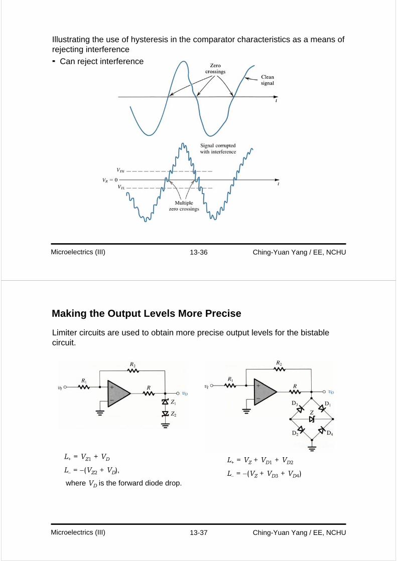
Making the Output Levels More Precise
Limiter circuits are used to obtain more precise output levels for the bistablecircuit.
L+ = VZ1 + VD
L− = −(VZ2 + VD),
where VD is the forward diode drop.
L+ = VZ + VD1 + VD2
L− = −(VZ + VD3 + VD4)
13-38 Ching-Yuan Yang / EE, NCHUMicroelectrics (III)
Generation of Square and Triangular Waveforms Using Astable Multivibrators
13-39 Ching-Yuan Yang / EE, NCHUMicroelectrics (III)
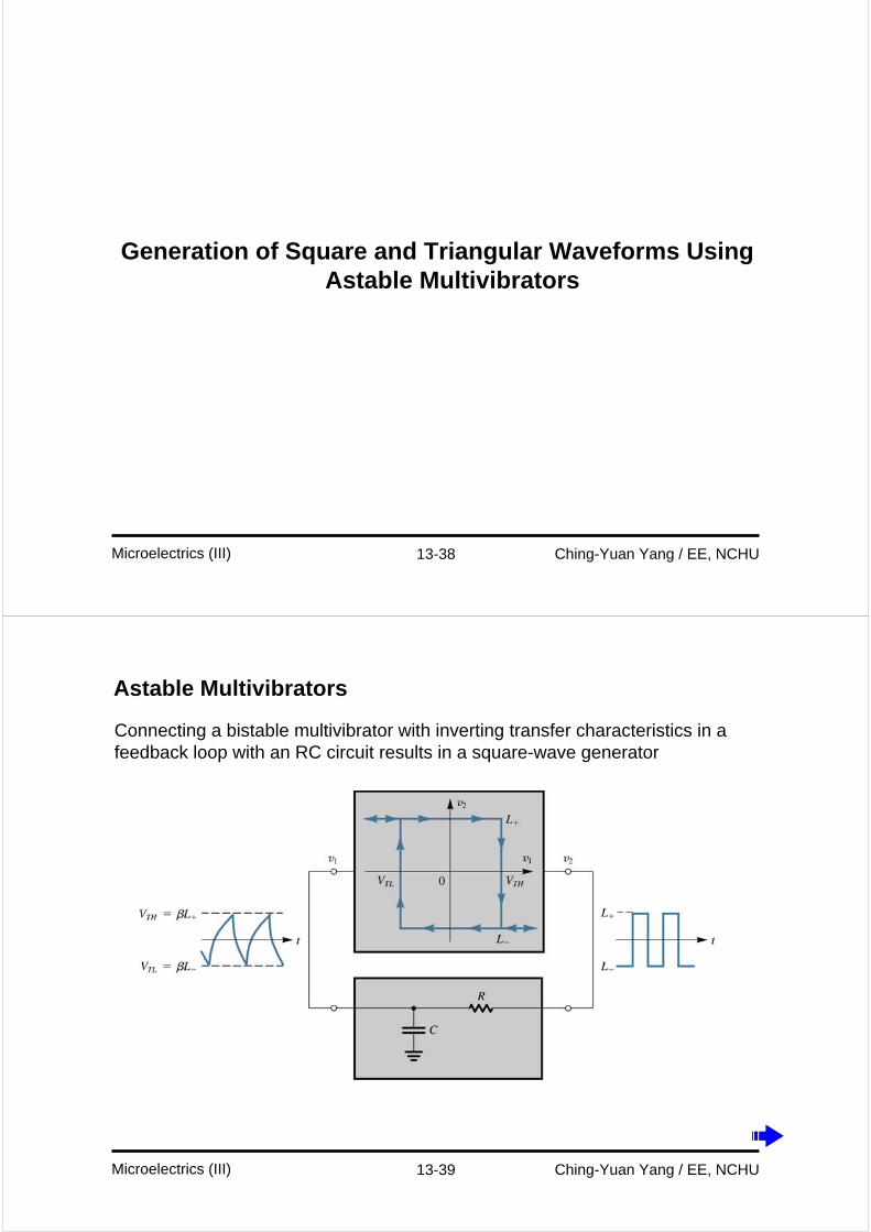
Astable Multivibrators
Connecting a bistable multivibrator with inverting transfer characteristics in a feedback loop with an RC circuit results in a square-wave generator
13-40 Ching-Yuan Yang / EE, NCHUMicroelectrics (III)
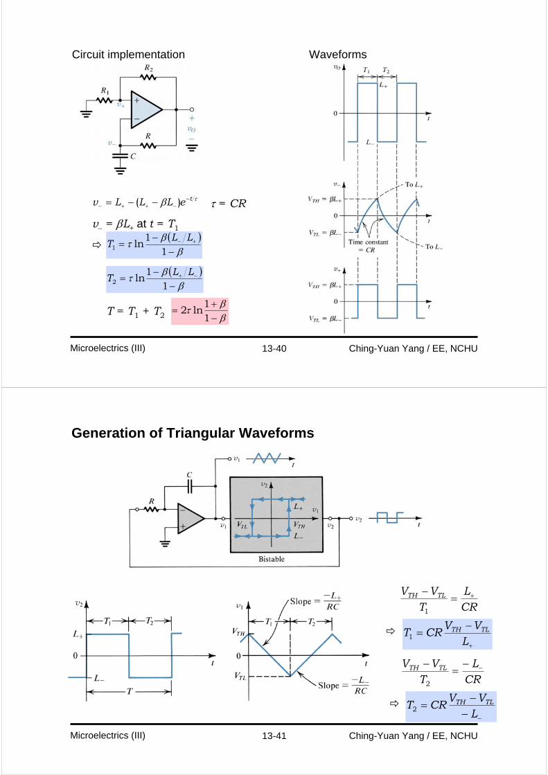
Circuit implementation Waveforms
τβ teLLLv −−++− −−= )( τ = CR
v− = βL+ at t = T1( )β
βτ−
−= +−
11
ln1LL
T
( )β
βτ−
−= −+
11
ln2LL
T
T = T1 + T2 ββτ
−+
=11
ln2
13-41 Ching-Yuan Yang / EE, NCHUMicroelectrics (III)
Generation of Triangular Waveforms
CRL
TVV TLTH +=
−
1
+
−=
LVV
CRT TLTH1
CRL
TVV TLTH −−
=−
2
−−−
=L
VVCRT TLTH
2
13-42 Ching-Yuan Yang / EE, NCHUMicroelectrics (III)
Generation of a Standardized Pulse – The MonostableMultivibrator
13-43 Ching-Yuan Yang / EE, NCHUMicroelectrics (III)
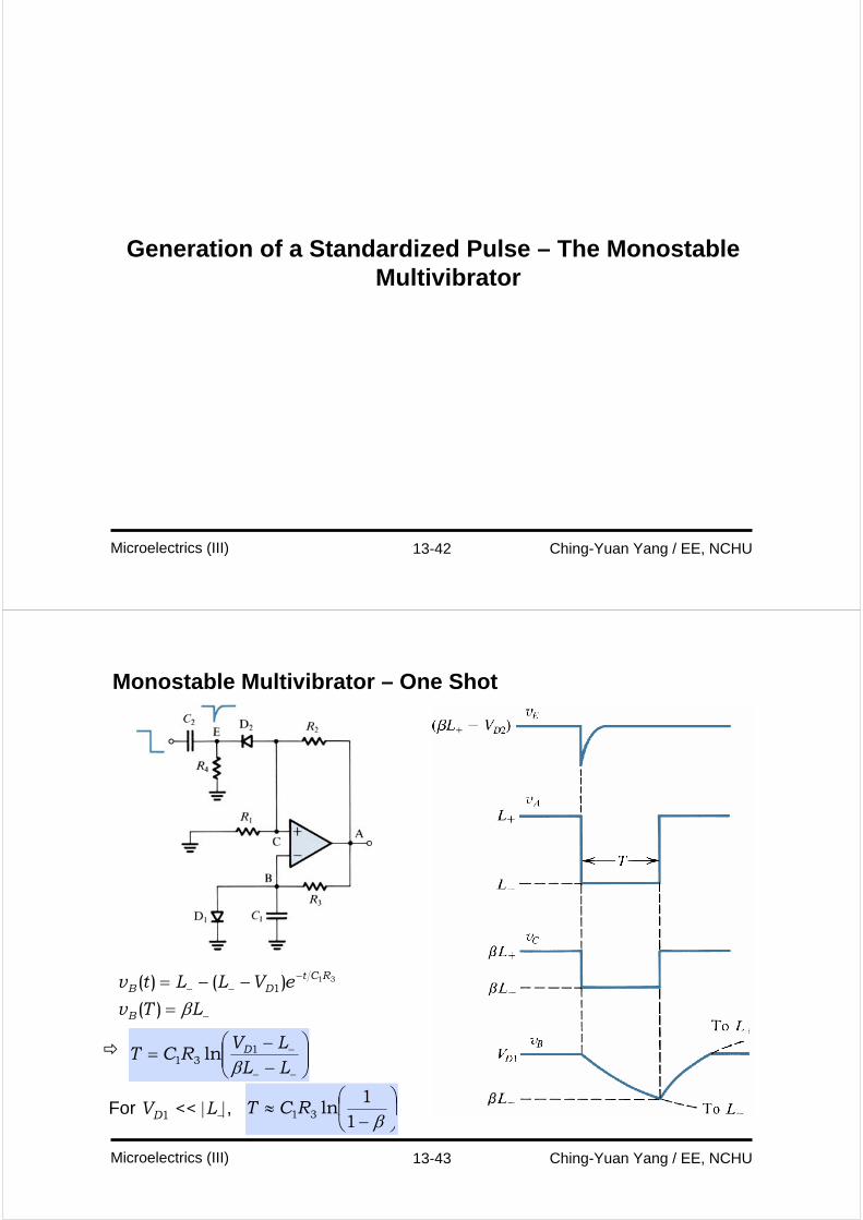
Monostable Multivibrator – One Shot
−
−−−
=−−=
LTv
eVLLtv
B
RCtDB
β)(
)()( 311
⎟⎟⎠
⎞⎜⎜⎝
⎛−−
=−−
−
LLLV
RCT D
β1
31 ln
For VD1 << |L−|, ⎟⎠
⎞⎜⎝
⎛−
≈β1
1ln31RCT
13-44 Ching-Yuan Yang / EE, NCHUMicroelectrics (III)
Integrated-Circuit Timers
13-45 Ching-Yuan Yang / EE, NCHUMicroelectrics (III)
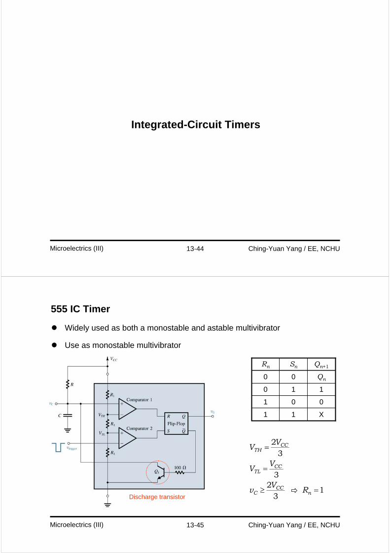
555 IC Timer
Widely used as both a monostable and astable multivibrator
Use as monostable multivibrator
Discharge transistor
X11
001
110
Qn00
Qn+1SnRn
CCTH
CCTL
CCC n
VV
VV
Vv R
=
=
≥ =
23
32
13
13-46 Ching-Yuan Yang / EE, NCHUMicroelectrics (III)
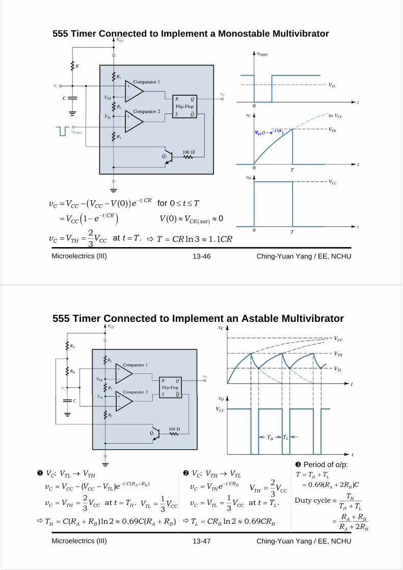
555 Timer Connected to Implement a Monostable Multivibrator
( )( )
for
0
at
( )
( )
( )
.
t CRC CC CC
t CRCC CE sat
C TH CC
v V V V e t T
V e V V
v V V t T
−
−
= − − ≤ ≤
= − ≈ ≈
= = =
0 0
1 0
23
CRCRT 1.13ln ≈=
1 t CRCCV e−−( )
13-47 Ching-Yuan Yang / EE, NCHUMicroelectrics (III)
555 Timer Connected to Implement an Astable Multivibrator
. at 32
)( )(
HCCTHC
RRCtTLCCCCC
TtVVv
eVVVv BA
===
−−= +−
)(69.02ln)( BABAH RRCRRCT +≈+=
CCTL VV31
=
VC: VTL → VTH VC: VTH → VTL
. at 31
LCCTLC
CRtTHC
TtVVv
eVv B
===
= −
BBL CRCRT 69.02ln ≈=
CCTH VV3
2=
Period of o/p:
0.69( 2 )H L
A B
T T T
R R C
= += +
BA
BA
LH
H
RRRR
TTT
2
cycleDuty
++
=
+≡
13-48 Ching-Yuan Yang / EE, NCHUMicroelectrics (III)
Homework
Problems 4, 13, 18, 24, 30, 40