Embed Size (px)
Citation preview
Signal Processing in Communications II:
CDMA
Samuel Sheng, Ph.D.
DataPath Systems, [email protected]
408-366-339115 August 99

Outline
• The Cellular Transmission Environment
• Direct-Sequence Code Division Multiple Access
• Signal Processing for CDMA
• The IS-95 CDMA Digital Cellular System
• The Next Generation: A Look at 3G Systems
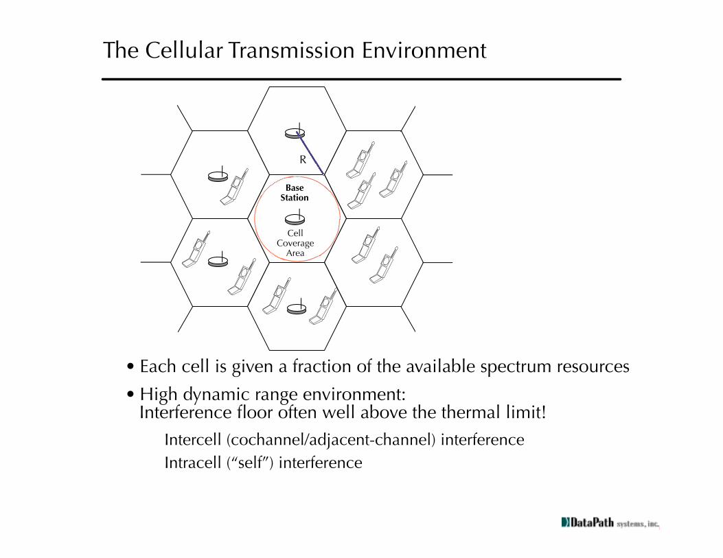
The Cellular Transmission Environment
R
BaseStation
CellCoverage
Area
• Each cell is given a fraction of the available spectrum resources
• High dynamic range environment:Interference floor often well above the thermal limit!
Intercell (cochannel/adjacent-channel) interference
Intracell (“self”) interference

Multipath Propagation and Shadowing
• Radio waves are blocked by objects: buildings, hills, etc.
• Dependent on local terrain, etc.
• Slowly time-varying amplitude shifts (long-term fading)
• Radio waves reflect off of objects: buildings, people, etc.
• Rapid time-varying amplitude shifts
• Intersymbol interference
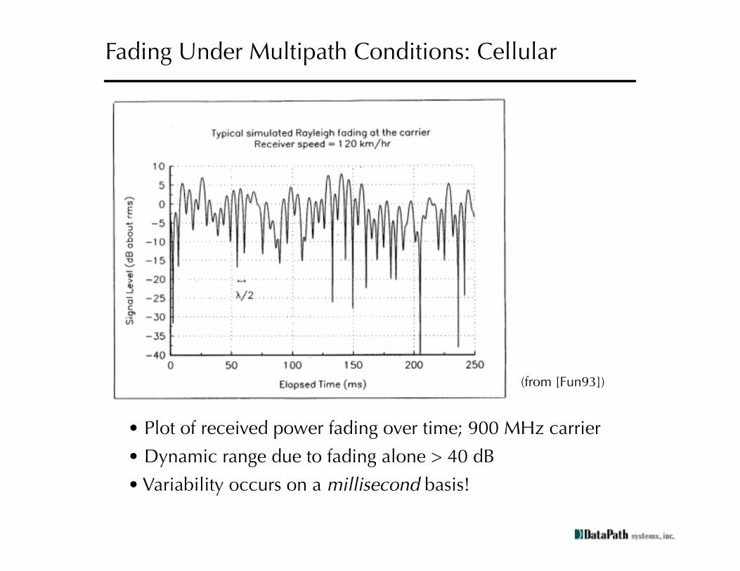
Fading Under Multipath Conditions: Cellular
(from [Fun93])
• Plot of received power fading over time; 900 MHz carrier
• Dynamic range due to fading alone > 40 dB
• Variability occurs on a
millisecond
basis!

Multipath Modeling
• Model the RF multipath channel as an FIR filter:
• Each
δ
(t-t
k
) represents one received multipath arrival
• Stochastic parameters:
• number of paths (n
p
)
• delay spread (t
n
- t
0
)
• local mean (slow fading component of a
k
)
• phase, amplitude variation (q
k
, a
k
)
h t( ) akδ t tk–( )ejqk
k 0=
np∑=Impulse Response
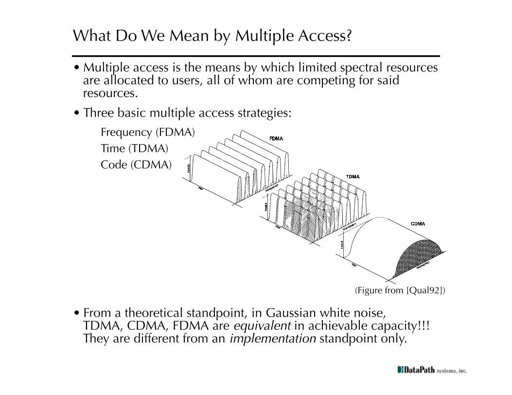
• Multiple access is the means by which limited spectral resources are allocated to users, all of whom are competing for said resources.
• Three basic multiple access strategies:
Frequency (FDMA)
Time (TDMA)
Code (CDMA)
• From a theoretical standpoint, in Gaussian white noise,TDMA, CDMA, FDMA are
equivalent
in achievable capacity!!!They are different from an
implementation
standpoint only.
What Do We Mean by Multiple Access?
(Figure from [Qual92])
•
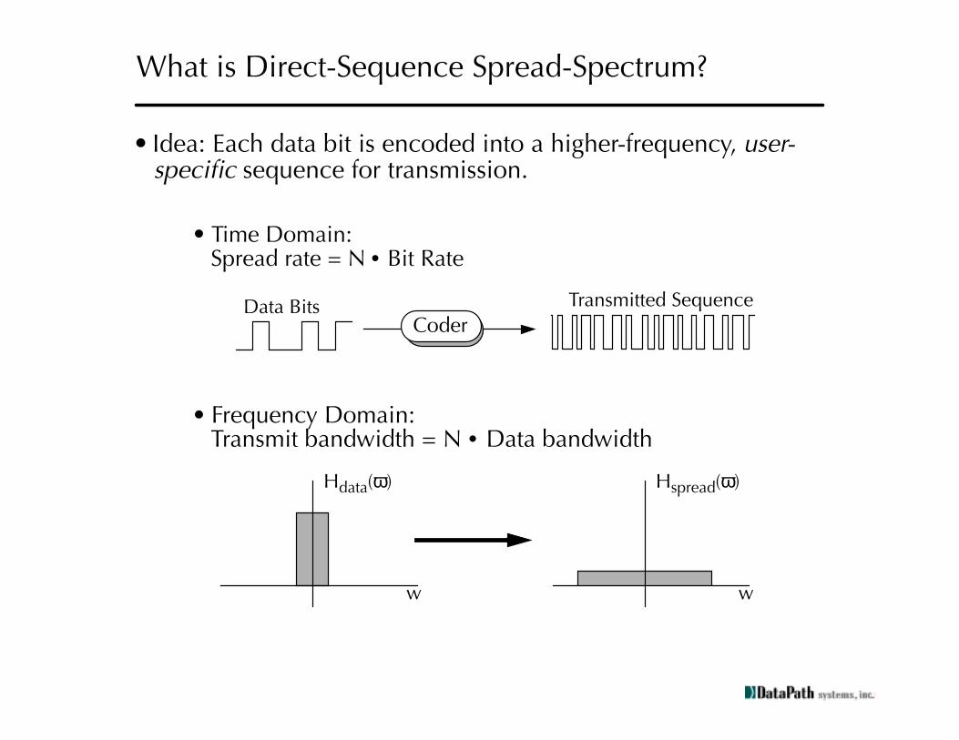
Idea: Each data bit is encoded into a higher-frequency,
user-specific
sequence for transmission.
•
Time Domain:Spread rate = N
•
Bit Rate
• Frequency Domain:Transmit bandwidth = N
•
Data bandwidth
What is Direct-Sequence Spread-Spectrum?
Data Bits
Coder
Transmitted Sequence
w
H
data
(
ω
)
w
H
spread
(
ω
)

Concepts in Orthogonality: A Little Story....
Suppose...
User 1 wants to transmit data symbol “a”
User 2 wants to transmit data symbol “b”
We allow both users transmit
at the same time
-but
at 4X the data rate!
User 1: a*(-1 1 -1 1). (-1 1 -1 1) is user 1’s
signature sequence
User 2: b*(1 1 1 1). (1 1 1 1) is user 2’s
signature sequence
So the receiver gets a sequence:
... (b-a), (b+a), (b-a), (b+a) ...
If we take an inner product of this with (-1, 1, -1, 1), we get (4*a)!
time
Because the two signature sequences are orthogonal,we can achieve perfect recovery in the receiver!!!

Properties of Spreading Codes
• Autocorrelation: spreading sequence s(n) should “look” like white noise. If s(n) is encoded as a sequence of +/- 1’s):
• Crosscorrelation: if s
a
(n) and s
b
(n) are both spreading sequences:
In practice, it is extremely difficult to meet both constraints simultaneously, for a reasonably large set of codes!
s i( )s i k–( )moduloN( )i 0=
N 1–
∑ Nδ k( )=
sa i( )sb i k–( )moduloN( )i 0=
N 1–
∑0 a not equal to b,
Nδ k( ), a equal to b=
+N
+/- 1
k

Direct-Sequence CDMA
User 1 Data
User 2 Data
User N Data
Coder
Coder
Coder
Orthogonal Signal
Spreading
Correlator
User 1 Data
User 1 Spreading
Sum of all user transmissions
Sequence
Users transmit at the sametime, in the same frequency!
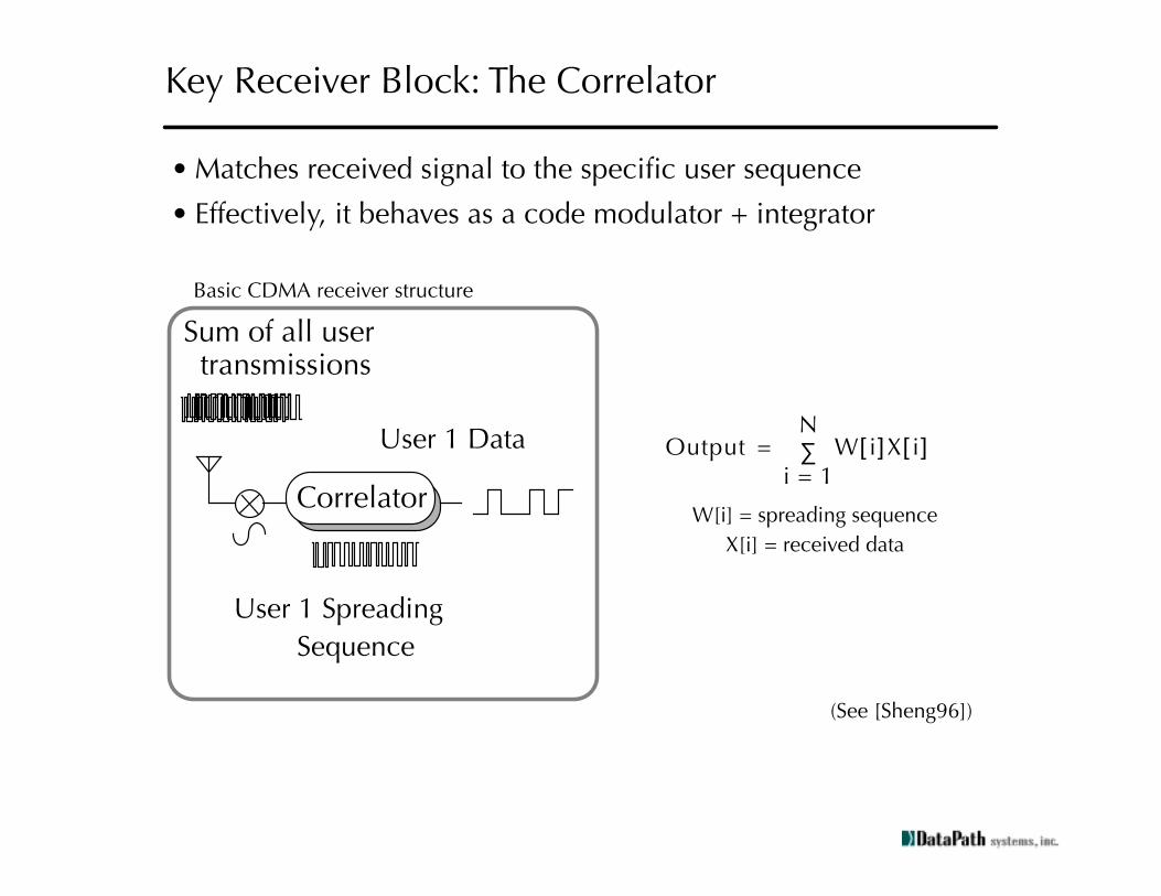
Key Receiver Block: The Correlator
• Matches received signal to the specific user sequence
• Effectively, it behaves as a code modulator + integrator
Correlator
User 1 Data
User 1 Spreading
Sum of all user transmissions
Sequence
Output W i
[ ]
X i
[ ]i 1=
N∑=
W[i] = spreading sequence
X[i] = received data
Basic CDMA receiver structure
(See [Sheng96])

Issues in Spread-Spectrum System Design
• The Near-Far Problem
• Most codes have finite crosscorrelation performance (codes can “leak” into each other)
• If one user close to antenna, one user far, the near user’s crosscorrelation leakage can swamp out the far user
• Extremely accurate power control is required
• Available code space
• Sufficient codes must exist to support the desired number of users / difficult for large number of users
• Receiver Timing Recovery
• Since we desire perfect autocorrelation (e.g, for multipath rejection), receiver timing is critical!
• Very accurate receiver timing recovery needed
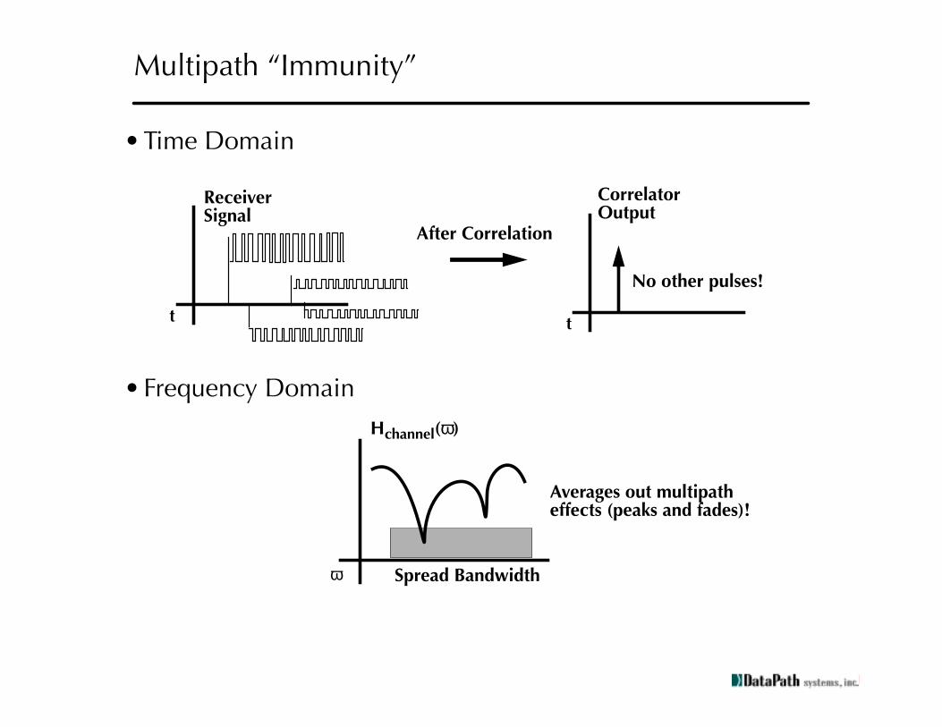
Multipath “Immunity”
• Time Domain
• Frequency Domain
No other pulses!
t
After Correlation
t
Receiver CorrelatorOutputSignal
ω
Hchannel(ω)
Spread Bandwidth
Averages out multipatheffects (peaks and fades)!

Resolving Multipath
Idea: since we have nearly perfect autocorrelation,can “scan” for multipath arrivals and resolve them.
Channel Impulse Response
0.0 16.0 32.0 48.0 time (nsec)
0.0
0.2
0.4
0.6
0.8
1.0
1.2
1.0
0.5
0.1
Prechannel Transmit Signal
time (nsec x 103)
-1.50
-1.00
-0.50
0.00
0.50
1.00
1.50
0.0 1.0 2.0 3.0
normalizedsignal
Postchannel Receive Signal
-2.00
-1.50
-1.00
-0.50
0.00
0.50
1.00
1.50
2.00
0.0 1.0 2.0 3.0
normalizedsignal
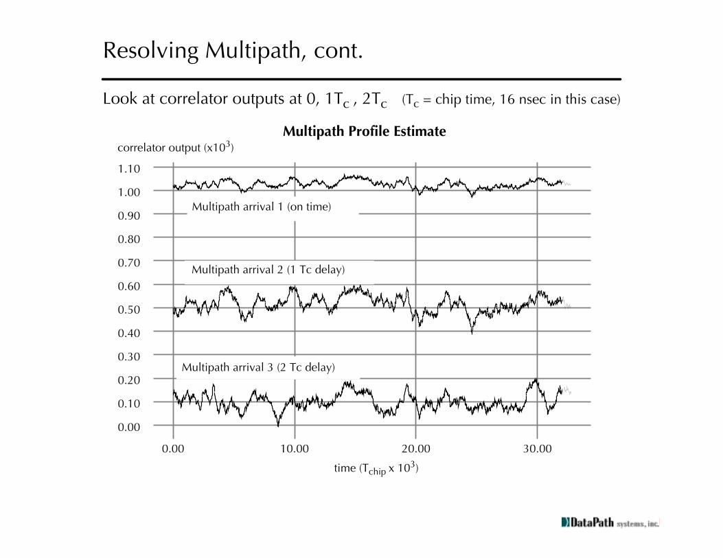
Resolving Multipath, cont.
Multipath Profile Estimate
0.00
0.10
0.20
0.30
0.40
0.50
0.60
0.70
0.80
0.90
1.00
1.10
0.00 10.00 20.00 30.00
correlator output (x103)
Multipath arrival 3 (2 Tc delay)
Multipath arrival 2 (1 Tc delay)
Multipath arrival 1 (on time)
time (Tchip x 103)
Look at correlator outputs at 0, 1Tc , 2Tc (T c = chip time, 16 nsec in this case)

Comments
• Key point: via signal processing, you can figure out what the channel looks like!
• Intuitively, can only really “resolve” multipath arrivals to a time accuracy of T
chip
• The number of
resolvable paths
must be related to the multipath delay spread. In particular, N
resolvable
= (Delay spread/T
chip
) + 1
• The higher the spreading factor, the better resolvability/immunity you have
• “Time diversity” - transmit data is distinctly replicated in time by the multipath
• How to take advantage of this?
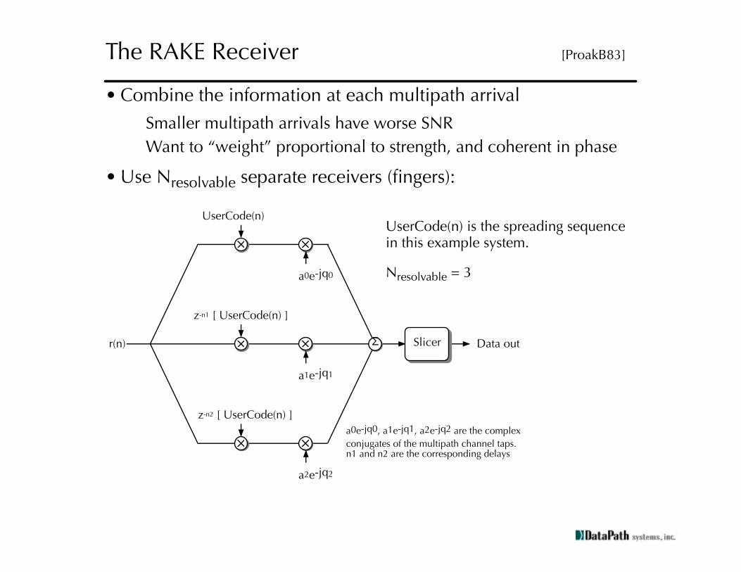
r(n)
z-n1 [ UserCode(n) ]
UserCode(n)
a2e-jq2
z-n2 [ UserCode(n) ]
Σ Slicer Data out
a0e-jq0, a1e-jq1, a2e-jq2 are the complex
conjugates of the multipath channel taps. n1 and n2 are the corresponding delays
a1e-jq1
a0e-jq0
The RAKE Receiver
[ProakB83]
• Combine the information at each multipath arrival
Smaller multipath arrivals have worse SNR
Want to “weight” proportional to strength, and coherent in phase
• Use N
resolvable
separate receivers (fingers):
UserCode(n) is the spreading sequencein this example system.
N
resolvable
= 3

The RAKE Receiver, cont.
• How much SNR improvement?
• Assuming that the noise is uncorrelated and white in all fingers of the RAKE:
(where {a
k
e
jq
k
} are the complex-valued coefficients of the multipath arrivals, and k is summed from 0 to (N
resolv
- 1))
SNRincrease dB
( )
10aka0------
2
k
∑
log=

The IS-95 CDMA Digital Cellular System
Specification IS-95
Access Method Combined CDMA / FDMA
Analog channel Bandwidth 1.25 MHz, + 270 kHz guardband
Channel Chip Rate 1.2288 MHz
Spreading Factor 64
Processing Gain 18.1 dB
Carrier Frequency
Downlink (Base Station to Mobile)Uplink (Mobile to Base Station)
869-894 MHz824-849 MHz
Baseband Modulation QPSK (downlink) / Offset QPSK (uplink)
Users / Channel Up to 62 (+1 pilot, +1 sync)
Total Available Frequency Channels 20 (however, only 10 available due to AMPS compatibility)
Spread-Spectrum Coding Length 32768 PN (scrambling)Length 64 Walsh (per user)
Pilot-assisted synchronization
Handoff Mobile Assisted, Soft Handoff
Cell Structure 3 sectors/cell, offset PN code per cell

Pilot Channel: all 0's
Walsh 0 (constant)
+
+
+
+
++
+
Walsh i
I-Channel Pilot PN Sequence
Power control
Conv. Encodeand Repetition
BlockInterleave
19.2 ksps
1.288 MHz
User i'sLong Code
Mask
Long CodePN Generator Scrambling
Q-Channel Pilot PN SequenceSe
lect
XOR
User i Data Modulator
User iData
1.2 kbps2.4 kbps4.8 kbps9.6 kbps
QPSK Signal
Forward Link Channelization
(Data & Pilot channels only)

Pilot Channel: Constant
Walsh 0 (constant)
++
I-Channel Pilot PN Sequence
Q-Channel Pilot PN Sequence
+
The Pilot Tone
• PIlot tone consists of PN sequence only
• Leverage off of outstanding autocorrelation performance
Timing recovery
Adjacent cell detection
Multipath estimation
Precision power control/measurement
• Note that pilot tone detection/estimation can be done
independent
of data detection in the receiver!

Power Control for the Forward Link
• Achievable downlink system capacity a function of SNR
• How to accommodate variable user voice activity/data rate?
For lower data rate, use repetition coding:
9600 kbps = full rate voice
4800 kbps = half rate voice, repeat bits twice at lower tx power
• Modulates transmit power as a function of:
Required data rate / voice activity
Mobile received signal quality (0.5 dB accurate power control)
User Data Rate 9600 4800 2400 1200
ECC Coding Rate 1/2 1/2 1/2 1/2
Data Repetition 1 2 4 8
Baseband Coded Rate
19.2k 19.2k 19.2k 19.2k
PN chip rate 1.23 Mcps 1.23 Mcps 1.23 Mcps 1.23 Mcps
Coding • Spreading 128X 256X 512X 1024X

+
+
+
I-Channel Pilot PN Sequence
Conv. Encodeand Repetition
BlockInterleave
1.288 MHz
User i'sLong Code
Mask
Long CodePN Generator Scrambling
Q-Channel Pilot PN Sequence
User iData
1.2 kbps2.4 kbps4.8 kbps9.6 kbps
64-AryWalsh
Modulation
BurstRandomizer
Del
ay
Off
set
QP
SK S
ign
al
Reverse Link Channelization
• Structurally very different from downlink
Downlink: user number determines the Walsh code (spreading)Uplink:
data
determines the Walsh code (modulation)
• Reason for this asymmetry: difficult to synchronize the uplink
• Users are separated entirely by the long code
• Power control required for near-far avoidance at base station
Closed-loop control achieves 0.5 dB power accuracy

Measured Transmitted Power in Mobile
• One interesting aspect of IS-95: mobile uplinks only as much power is needed, and no more:
• Can be extremely power efficient in the mobile!
(Figure from [QualC92])
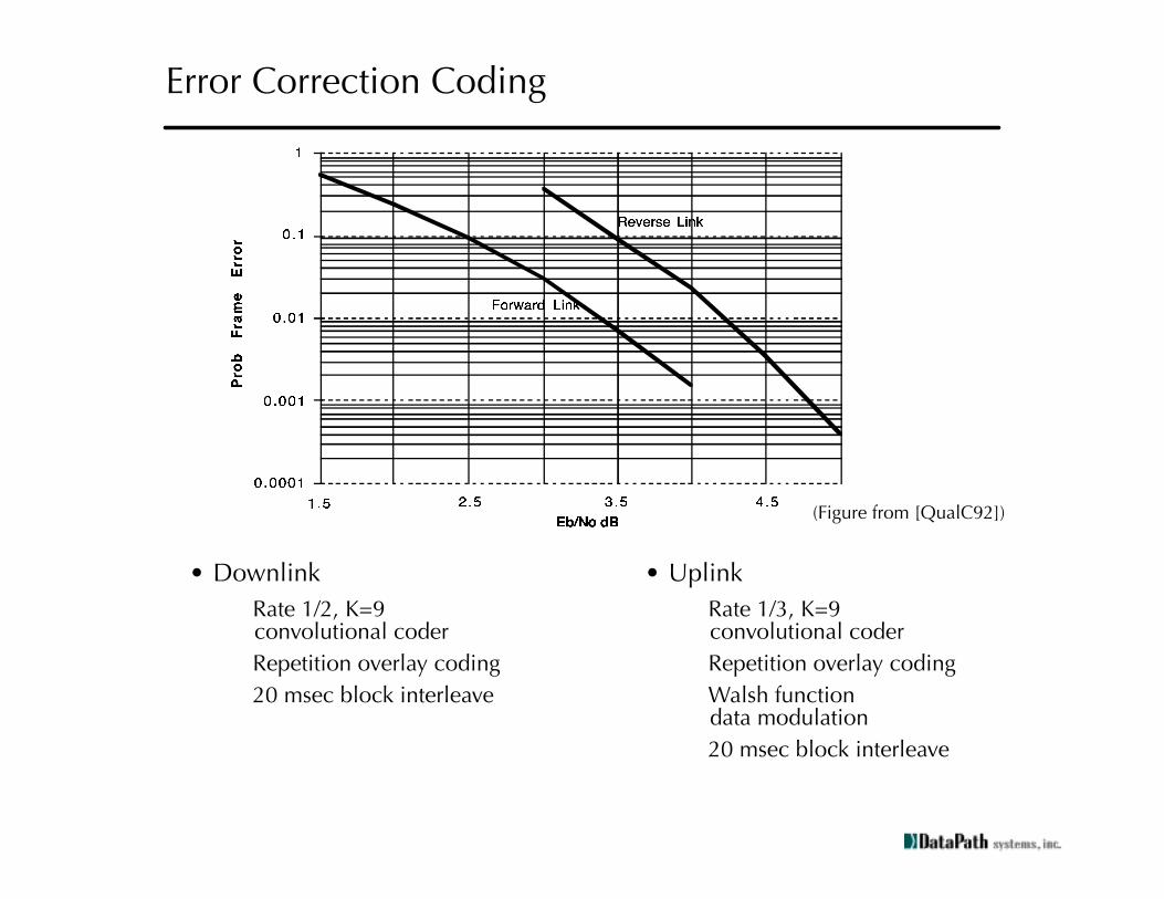
Error Correction Coding
• Downlink
Rate 1/2, K=9convolutional coder
Repetition overlay coding
20 msec block interleave
• Uplink
Rate 1/3, K=9convolutional coder
Repetition overlay coding
Walsh functiondata modulation
20 msec block interleave
(Figure from [QualC92])

Mobile Assisted Soft Handoff
• Mobile can sense pilot tone / measure power of adjacent cells
• Handoff is “soft”: the mobile can establish link with the adjacent cell before full handoff is performed
• Mobile is effectively in both cells simultaneously
(Figure from [QualC92])

From
AD
C
DataRecovery
Finger
Searcher
DataRecovery
Finger
DataRecovery
Finger
RA
KE
Com
bin
e /
Des
cram
ble
r /
Dei
nte
rlea
ver
ViterbiDecoder
Bits
Out
CoarseFrequencyTracking
Walsh iCorrelator
Pilot ToneCorrelator
PhaseCorrection
Decimate
TimingTracking
PhaseTracking
From
AD
C FingerOutput
Data Recovery Finger
Forward-Link Receiver: DSP Architecture
• Leverages timing recovery off of pilot tone detection
• Searcher block looks for:
Adjacent cells
Stronger multipath arrivals
• Three independent fingers used for RAKE recovery

CellDemodulator
Finger
CellDemodulator
Finger
CellDemodulator
Finger
RA
KE
Com
bin
e /
Des
cram
ble
r /
Dei
nte
rlea
verViterbi
Decoder
Bits
Out
CellDemodulator
Finger
Ante
nna
Bus:
3 (or
more
) poss
ible
cell s
ite
ante
nnas
Cell Demodulator Finger
FastHadamardTransform
PhaseCorrection
Decimate
TimingTracking Phase
Tracking
From
Ante
nna
Bus Timing /
FrequencyRecovery
Walshdecision,RX Energy
MaxAntenna
Select
Searcher1
Searcher2
Reverse-Link Receiver: DSP Architecture
• Significantly more complex: no pilot tone available
• Antenna diversity
Multipath mitigation
Can perform “micro-handoffs” within a cell (sectorized)
• Four independent fingers used for RAKE recovery

Third-Generation Digital Cellular (3G) Systems
• Goals of 3G Systems
Advanced services (video, data) in addition to voice
Minimum of 144 kbps/user data access, up to 384 kbps/user
Provision for 2 Mbps data access (limited coverage/mobility)
High spectrum efficiency
• Need to coexist with existing PCS systems (1.9 GHz band)
• Multiple proposals / standards
Two major ones are WCDMA and cdma2000
WCDMA cdma2000
Chip Rate 1.024, 4.096, 8.192,16.384 Mcpsdirect spread
1.2288, 3.6864, 7.3728, 11.0593, 14.7456 (direct spread);
n * 1.2288 Mcps (n = 1,3,6,9, 12)(multicarrier spread)
Carrier Spacing 1.25, 5, 10, 20 MHz 1.25, 5, 10, 15, 20 MHz
Inter-base station synchronization
Asynchronous Synchronous
Pilot Tone User dedicated time-interleaved pilot (both uplink and downlink);
common pilot in downlink
Time-interleaved per-userpilot in uplink
Common pilot in downlink

Signal Processing Aspects of 3G
• How to achieve greater spectral capacity?
• Use of more advanced spreading codes
Variable-rate Gold codes
Multicarrier methods
• Error correction techniques
High complexity convolutional codes (constraint length 9)
Concatenated block/convolutional coding
Turbo coding
• Multiuser detection

• CDMA systems have proven to be self-interference limited
Codes are not perfectly orthogonal under multipath!
• Idea: improve system performance/capacity by detecting data from all users and cancelling interference
• Simple example:
With 70% intracell interference, maximum achievable capacity gain by MUD is (1.3/0.3) = 3.9X!Limited by accuracy of multipath estimation, power control, etc.
r(n)
User 2 Code
User 1 Code
User n Code
User i Data
Multiuser Detection /InterferenceCancellation
Joint Estimation ofall users’ data (inter- or intra-cell)
Multiuser Detection
Conclusions
• CDMA provides a multiple access strategy well-suited to the cellular transmission environment
• Achieves this robustness mainly due to signal processing
Channel estimation
RAKE reception
Availability of synchronous pilot tone
Advanced error correction
Multiuser detection
• Such flexibility has made it the technology of choice for 3G systems!

Bibliography
[Cook83] C.E. Cook and H.S. Marsh. “An Introduction to Spread Spectrum,”IEEE Communications Magazine, pp. 8-16. March 1983.
[Dixon84] R.C. Dixon. Spread Spectrum Systems,2nd ed., New York: J. Wiley and Sons, 1984.
[Feher87] K. Feher. Advanced Digital Communications. New Jersey: Prentice-Hall Inc. 1987.
[Fun93] V. Fung, T.S. Rappaport, B. Thoma. “Bit-Error Simulation for p/4 DQPSK Mobile Radio Communication Using Two-Ray and Measurement-Based Impulse Response Models,” IEEE Journal on Selected Areas in Communications, Vol. 11, No. 3, pp. 393-405, April 1993.
[Lee88] E.A. Lee and D.G. Messerschmitt. Digital Communication. New York:Kluwer Academic Publishers, 1988.
[Lee89] W. C-Y Lee. Mobile Cellular Telecommunications Systems. New York:McGraw-Hill Book Co., 1989
[Ojan98] T. Ojanpera, R. Prasad, ed. Wideband CDMA for Third Generation Mobile Communications. Boston, MA: Artech House, 1998
[Peroul94] J. Peroulas. Design and implementation of a High-Speed CDMA Modulator for the INFOPAD Basestation. M.S. Thesis, U.C. Berkeley, Berkeley, CA, 1996.
[Pick82] R.L. Pickholtz and D.L. Schilling. “Theory of Spread-Spectrum Communications - A Tutorial.” IEEE Transactions on Communications, Vol. COM-30, No. 5, pp. 855-883. May 1982.
[ProakB83] J.G. Proakis. Digital Communications. New York: McGraw-Hill Book Co., 1983
[Qual92] EIA/TIA IS-95 Interim Standard, Wideband Spread-Spectrum Digital Cellular Dual-Mode Mobile Station-Base station Compatibility Standard.Telecommunications Industry Association, April 1992.
[QualC92] An Overview of the Application of Code Division Multiple Access (CDMA) to Digital Cellular Systems and Personal Cellular Networks.Qualcomm Inc., May 21, 1992.

[Rapp96] T.S Rappaport. Wireless Communications: Principles and Practice.New Jersey: Prentice-Hall PTR, 1996.
[Saleh87] A.M. Saleh and R. A. Valenzuela. “A Statistical Model for Indoor Multipath Propagation.” IEEE Journal of Selected Areas in Communications, Vol. SAC-5, No. 2, pp. 128-137. February 1987.
[Schill90] D.L. Schilling, R.L. Pickholtz, and L.H Milstein, eds. “Spread-Spectrum Communications I and II.” Special Issues of the IEEE Journal of Selected Areas in Communications, Vol. JSAC-8, No. 4-5. May-June 1990.
[Sheng96] S. Sheng, L. Lynn, J. Peroulas, K. Stone, et al. “A Low-Power CMOS Chipset for Spread-Spectrum Communications.” IEEE 1996 International Solid-State Circuits Conference, San Francisco, CA Feb. 1996.
[Sheng98] S. Sheng. Low-Power CMOS Wireless Communications. Massachusetts: Kluwer Academic Publishers, 1998.
[Simon85] M.K. Simon, et al. Spread-Spectrum Communications, Vol. 1-3. New York:Computer Science Press Inc., 1985.
[Verdu98] S. Verdu. Multiuser Detection. New York: Cambridge University Press, 1998.
[Viter95] A.J. Viterbi. CDMA: Principles of Spread Spectrum Communications. Reading, MA: Addison-Wesley Pub. Co., 1995.