Embed Size (px)
Citation preview
1
CHAPTER-1
INTRODUCTION
In this chapter, we present an overview of wireless communications, Orthogonal
frequency division multiplexing (OFDM), multiple-input multiple-output
Orthogonal frequency division multiplexing ( MIMO-OFDM) , Space-Time-Block-
Coded Orthogonal frequency division multiplexing (STBC-OFDM), Space-
Frequency-Block-Coding Orthogonal frequency division multiplexing (SFBC-
OFDM) , literature review, problem description and organization of the thesis.
1.1 WIRELESS COMMUNICATIONS
The ever increasing demand for very high rate wireless data transmission calls
for technologies that maximize spectral efficiency (bits per second per Hertz),
robustness against multipath propagation, range of the communication system and
minimizes power consumption as well as implementation complexity. These
objectives are often conflicting and hence techniques and implementations are
sought which offer the best possible tradeoff among them.
1.1.1 Wireless Channel Models
Since the selection of modulation scheme and ultimate design of any communication
depends on the characteristics of the channel, we present the characteristics and
modeling of flat and frequency selective fading channels which either remain constant
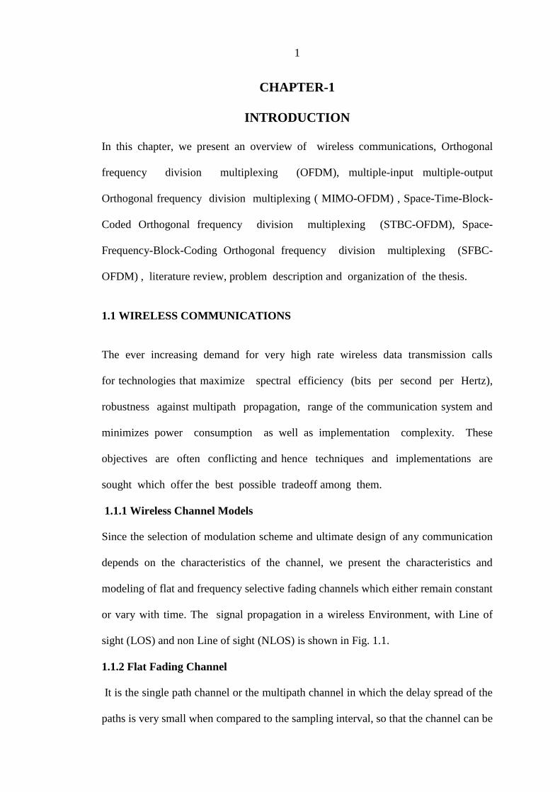
or vary with time. The signal propagation in a wireless Environment, with Line of
sight (LOS) and non Line of sight (NLOS) is shown in Fig. 1.1.
1.1.2 Flat Fading Channel
It is the single path channel or the multipath channel in which the delay spread of the
paths is very small when compared to the sampling interval, so that the channel can be
2
modeled as a single tap filter. The multipath structure of the channel is such that the
spectral characteristics of the transmitted signal are preserved at the receiver.
The strength of the received signal changes with time due to fluctuations in the gain
of the channel caused by multipath [2]. This channel is either Additive White
Gaussian Noise (AWGN) channel or Rayleigh faded channel or Rician faded
channel.
scatterer
scatterer
scatterer
(a) LOS environment
Line of Sight
Mobile Receiver
scatterer
scatterer
scatterer
(b)NLOS environment
Mobile Receiver
Fig. 1.1 Signal Propagation in a Wireless Environment, with and without LOS
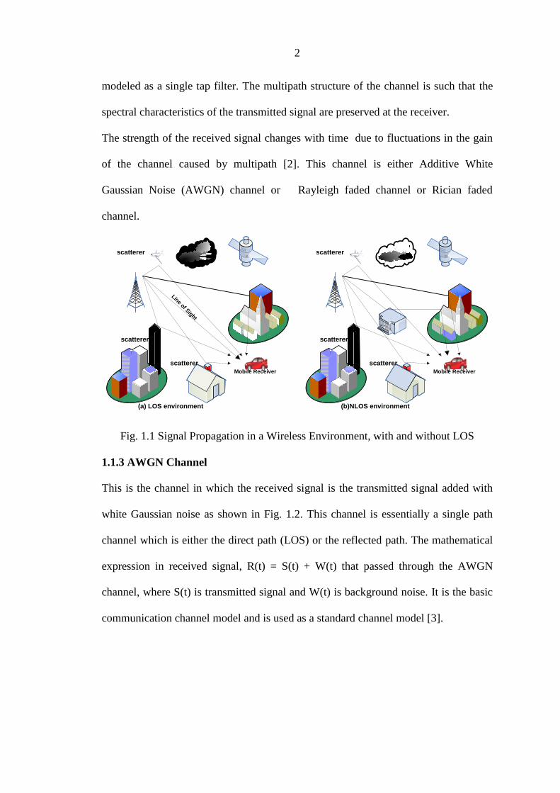
1.1.3 AWGN Channel
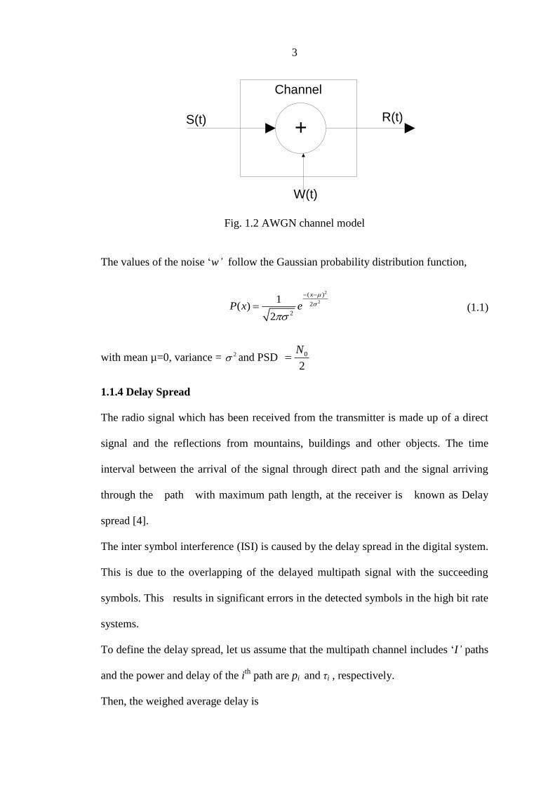
This is the channel in which the received signal is the transmitted signal added with
white Gaussian noise as shown in Fig. 1.2. This channel is essentially a single path
channel which is either the direct path (LOS) or the reflected path. The mathematical
expression in received signal, R(t) = S(t) + W(t) that passed through the AWGN
channel, where S(t) is transmitted signal and W(t) is background noise. It is the basic
communication channel model and is used as a standard channel model [3].
3
S(t)
Channel
+R(t)
W(t)
Fig. 1.2 AWGN channel model
The values of the noise „w’ follow the Gaussian probability distribution function,
2
2
( )
2
2
1( )
2
x
P x e
(1.1)
with mean µ=0, variance = 2 and PSD 0
2
N
1.1.4 Delay Spread
The radio signal which has been received from the transmitter is made up of a direct
signal and the reflections from mountains, buildings and other objects. The time
interval between the arrival of the signal through direct path and the signal arriving
through the path with maximum path length, at the receiver is known as Delay
spread [4].
The inter symbol interference (ISI) is caused by the delay spread in the digital system.
This is due to the overlapping of the delayed multipath signal with the succeeding
symbols. This results in significant errors in the detected symbols in the high bit rate
systems.
To define the delay spread, let us assume that the multipath channel includes „I’ paths
and the power and delay of the ith
path are pi and τi , respectively.
Then, the weighed average delay is
4
1
1
I
i i
i
I
i
i
p
p
(1.2)
Delay spread is defined as
2 2
Where
2
2 1
1
I
i i
i
I
i
i
p
p
(1.3)
The channel “coherence bandwidth” is approximated by, 1
5cB
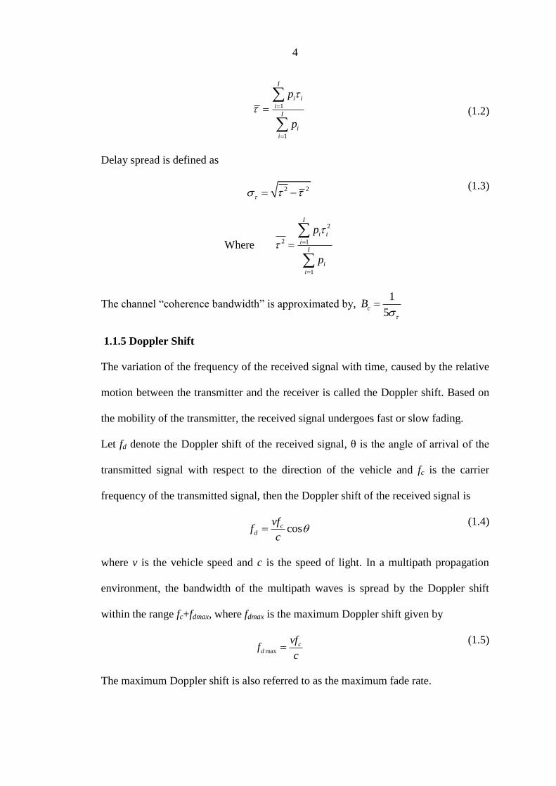
1.1.5 Doppler Shift
The variation of the frequency of the received signal with time, caused by the relative
motion between the transmitter and the receiver is called the Doppler shift. Based on
the mobility of the transmitter, the received signal undergoes fast or slow fading.
Let fd denote the Doppler shift of the received signal, θ is the angle of arrival of the
transmitted signal with respect to the direction of the vehicle and fc is the carrier
frequency of the transmitted signal, then the Doppler shift of the received signal is
coscd
vff
c
(1.4)
where v is the vehicle speed and c is the speed of light. In a multipath propagation
environment, the bandwidth of the multipath waves is spread by the Doppler shift
within the range fc+fdmax, where fdmax is the maximum Doppler shift given by
maxc
d
vff
c
(1.5)
The maximum Doppler shift is also referred to as the maximum fade rate.
5
The coherence time, Tc is defined as the time over which the time correlation function
takes values above 0.5 [5]. It is defined as
max
9
16cT
f
(1.6)
In fast fading, the coherence time is smaller than the symbol period.
1.1.6 Rayleigh Fading
When there is large number of paths, applying Central Limit Theorem, each path can
be modeled as circularly symmetric complex Gaussian random variable. This model is
called Rayleigh fading channel model. Rayleigh distribution is commonly used to
describe the statistical time varying nature of the received envelope of a flat fading
signal, or the envelope of an individual multipath component. Envelope of the sum of
two quadrature Gaussian noise signals of zero mean obeys a Rayleigh distribution.
Flat fading channels are also known as amplitude varying channel.
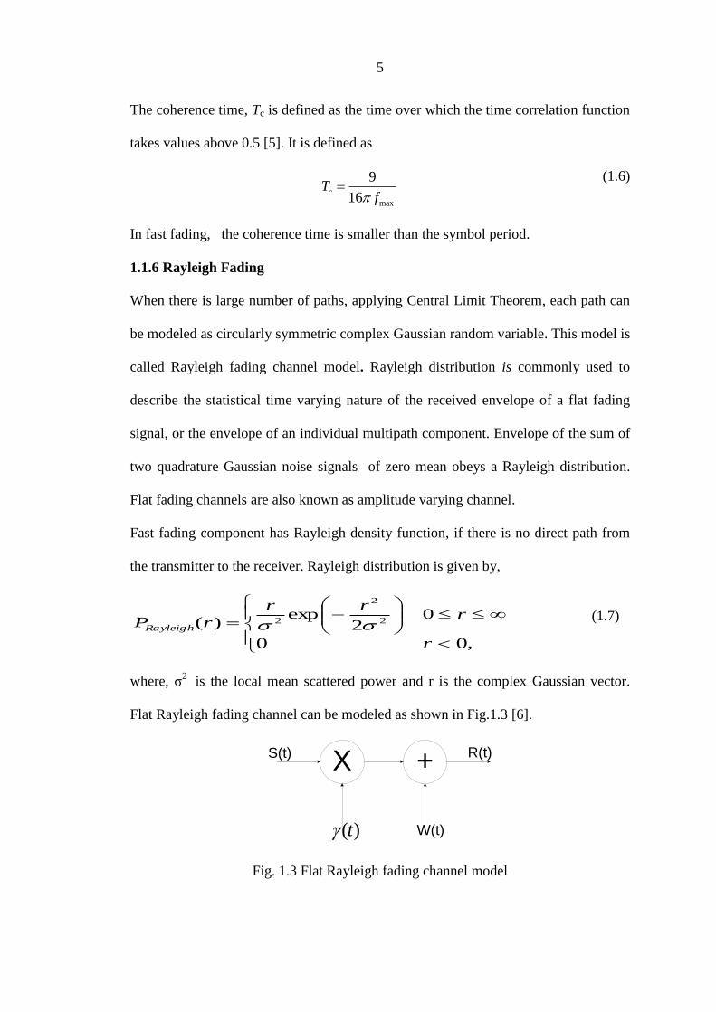
Fast fading component has Rayleigh density function, if there is no direct path from
the transmitter to the receiver. Rayleigh distribution is given by,
,00
02
exp)( 2
2
2
r
rrr
rPRayleigh
(1.7)
where, σ2
is the local mean scattered power and r is the complex Gaussian vector.
Flat Rayleigh fading channel can be modeled as shown in Fig.1.3 [6].
R(t)X +S(t)
W(t)( )t
Fig. 1.3 Flat Rayleigh fading channel model

6
If either the transmitter or receiver is in motion, the fading term ( )t can be
appropriately represented as a zero mean Gaussian process with a power spectral
density (PSD) of
2( )
1 ( / )
Rd
d
PS f f f
f f
(1.8)
The received power is represented as PR, and the Doppler frequency is represented as
fd. Average fade duration primarily depends upon the speed of the mobile, and
decreases as the maximum Doppler frequency fd becomes large. Average fade
duration is defined as the average period of time for which the received signal is
below a specified level R. Rayleigh fading is usually adopted for flat fading channel
model [7].
1.1.7 Rician Fading Channel
When a dominant stationary (non-fading) signal component is present, such as a
line-of-sight propagation path, the small-scale fading envelope distribution is Rician.
Rician fading model and Rayleigh models are allmost all identical but the only
difference is that, Rician fading model has a strong dominant component arriving
through LOS path, due to which the quadrature Gaussian noise components in the
complex Gaussian noise have non zero mean [8].
If there is a direct path, fast fading component will have Rician density function,
which is given by,
2 2
2
( )
2
02 2 0; 0( ) ,
r A
rician A r
r rAp r e I
(1.9)
where, 2
0 2 2
0
1 cosexp
2
rA rAI d

7
Here r is the complex Gaussian vector. σ2
is the local mean scattered power and A2
is
the power of the dominant component.
1.1.8 Frequency-Selective Fading Channel
Frequency selective fading channel model is usually modeled as the sum of several
flat fading channels with different delays. When the multipath delay spread is
significant with respect to the symbol period, the channel acts as a multitap filter, in
which each filter coefficient (each tap) is Rayleigh distributed in the case of rayleigh
faded channel and only the first coefficient is of non zero mean, if it is Rician faded
channel. Conceptually, the channel‟s pass band bandwidth is smaller than the
transmitted signal‟s bandwidth resulting in distortion of the transmitted signal. The
term frequency selective comes from the observation that the channel exhibits
different gains for different frequency components. The channel possesses a constant-
gain and linear phase response over a bandwidth that is smaller than the bandwidth of
the channel. The received signal includes multiple versions of the transmitted
waveform which are attenuated and delayed in time. Certain frequency components
in the received signal spectrum have greater gains than others [9].
1.1.9 Time Flat and Time Selective Channels
If the Doppler spread experienced by the signal due to relative motion between the
transmitter and the receiver is very small, when compared to the frequency of the
operation and its coherent time of the channel is smaller than the symbol duration then
it is called as the time flat channel. Otherwise it is called time selective channel. It
can be singletap or multitap channel. If the channel is time varying but is almost
constant during the symbol period (during the interval in which the frame is
transmitted in OFDM ), it is said to be the quasi-static channel [10].

8
1.2 FDM- AN OVERVIEW
Frequency Division Multiplexing (FDM) is the technique used to simultaneously
transmit several signals through the channel that supports a larger bandwidth. The
available channel bandwidth is divided into a number of non-overlapping bands of
frequencies separated by guard bands. Each band of frequencies is allocated to a
user, into which the user translates the spectrum of the information signal using a
carrier and transmits it as a bandpass signal. If sufficient amount of carrier is also
added to the translated spectrum, it is called the amplitude modulation (AM). In AM,
the spectrum of desired signal is obtained by using a bandpass filter and is
demodulated using envelope detector. This does not require the same carrier to be
generated at the receiver using to produce the modulated signal. But the
disadvantage of this system is that large amount of power of the transmitted signal is
the carrier power, because of which its power efficiency is low. If the carrier is not
added to the translated spectrum, it is called the double side band suppressed carrier
(DSBSC) modulation. Its power efficiency is high but it requires coherent carrier to
be generated at the receiver to demodulate the signal. This makes the receiver more
complicated. The demodulator consists of a product modulator which multiplies the
received signal with the coherent carrier and a low-pass filter. With DSBSC, using a
process called the quadrature carrier multiplexing (QAM), two different signals can
be transmitted using orthogonal carriers of same frequency and the same band of
frequencies [11]. Let m1(t) and m2(t) be the signals with cos(2πfct) and sin(2πfct) as
the orthogonal carriers. The transmitted signal is
1 2( ) ( )cos(2 ) ( )sin(2 )c cs t m t f t m t f t (1.10)
If we demodulate this signal using cos(2πfct), we get m1(t) since it is orthogonal to

9
sin(2πfct). Similarly by demodulating using sin(2πfct), we get m2(t). It is important to
note here that, if the carriers are orthogonal then the individual signals can be detected
even though their spectra overlap. The pre-envelope of s(t), denoted by s+(t), which
is complex, is given by
2
1 2( ) ( ( ) ( )) ci f ts t m t im t e
(1.12)
where real part of which is s(t), and the complex envelope of which is m1(t) − i
m2(t). In digital communications, if Xm is the complex symbol transmitted at t = mTb
and p(t) is the rectangular pulse, then
1 2( ) ( ) ( )m bm t im t X p t mT (1.13)
If we sample s+(t) at a rate 1
bT at the instances nTb with
1
cf = T = NTb, we get xn,
(n = 0, …, ,N – 1), given by
2i n
Nn mx X e
(1.14)
which is the discrete-time representation of s+(t). If we have N samples of xn, then Xm
can be obtained by using the formula
21
0
1i nN
Nm n
n
X x eN
(1.15)
1.3 OFDM
Consider the carriers cos(2πkfct) for integer values of k. These carriers are orthogonal
in the interval T = 1
cf. If we sample the pre-envelopes of these carriers in such a way
that there are N samples in the interval T, we get N different complex exponential
10
carriers given by
2j kn
Ne
, 1 ≤ k ≤ N. These carriers are orthogonal over N samples.
The complex envelope of this set of carriers gives their complex base band
representation, given by
2j kn
Ne
, 0 ≤ k ≤ N − 1. If we modulate the kth
carrier by a
complex symbol Xk, and collect the first N samples, we get the kth
modulated carrier
sequence, given by [8] [12]
2
,0 1i kn
k Nn kx X e n N
(1.16)
The sum of all the modulated carrier sequences scaled by 1
N is
21
0
1, 0 1
i knN
Nn k
k
x X e n NN
(1.17)
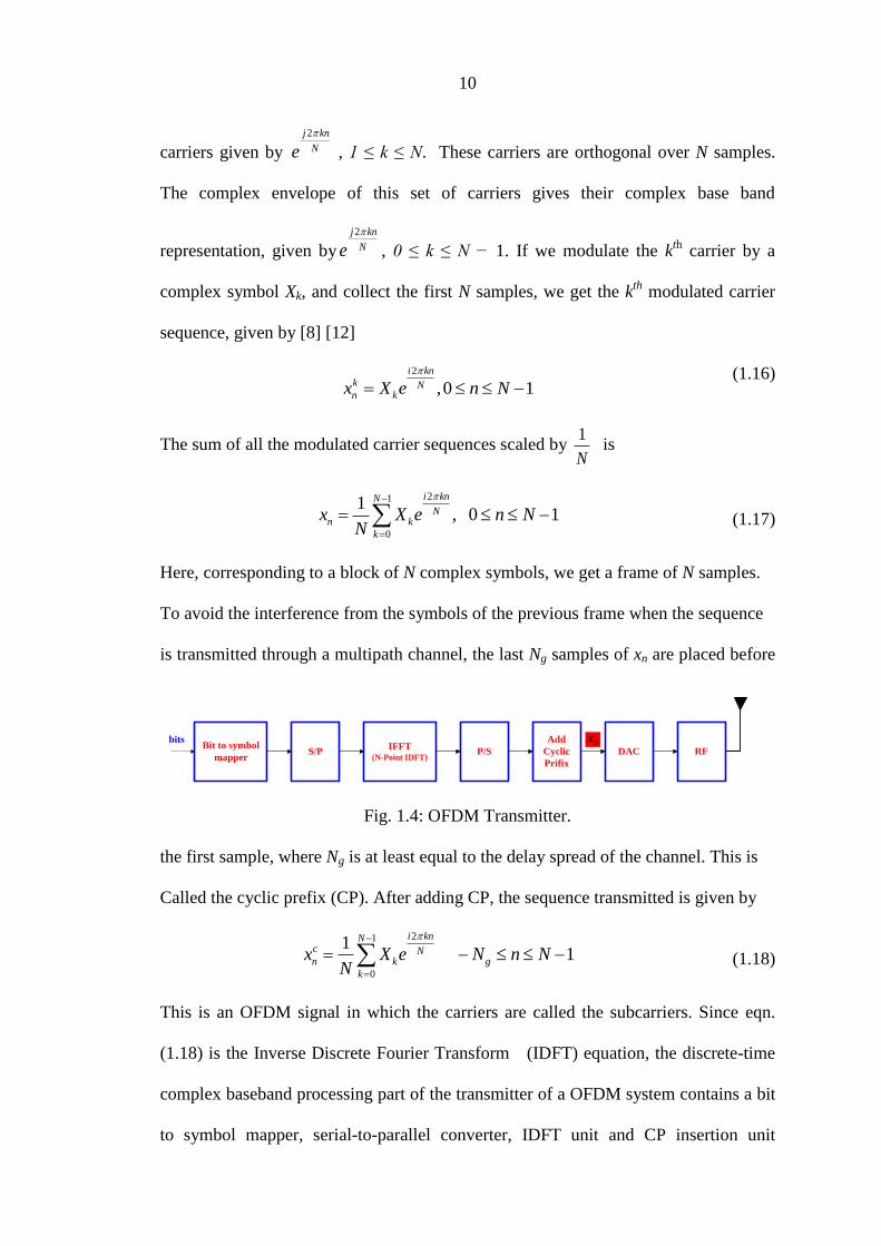
Here, corresponding to a block of N complex symbols, we get a frame of N samples.
To avoid the interference from the symbols of the previous frame when the sequence
is transmitted through a multipath channel, the last Ng samples of xn are placed before
IFFT(N-Point IDFT)
Add
Cyclic
Prifix
DAC RFP/SS/PBit to symbol
mapper
bits nx
Fig. 1.4: OFDM Transmitter.
the first sample, where Ng is at least equal to the delay spread of the channel. This is
Called the cyclic prefix (CP). After adding CP, the sequence transmitted is given by
21
0
11
i knNc Nn k g
k
x X e N n NN
(1.18)
This is an OFDM signal in which the carriers are called the subcarriers. Since eqn.
(1.18) is the Inverse Discrete Fourier Transform (IDFT) equation, the discrete-time
complex baseband processing part of the transmitter of a OFDM system contains a bit
to symbol mapper, serial-to-parallel converter, IDFT unit and CP insertion unit
11
followed by parallel-to-serial converter as shown in Fig. 1.4. In a practical system, the
output is converted to an analog signal using a digital-to-analog converter (DAC),
translated in to radio frequency (RF) spectrum and transmitted.
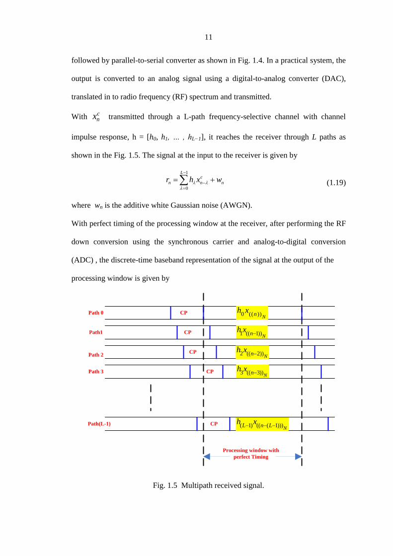
With cnx transmitted through a L-path frequency-selective channel with channel
impulse response, h = [h0, h1, … , hL−1], it reaches the receiver through L paths as
shown in the Fig. 1.5. The signal at the input to the receiver is given by
1
0
Lc
n n nr h x w
(1.19)
where wn is the additive white Gaussian noise (AWGN).
With perfect timing of the processing window at the receiver, after performing the RF
down conversion using the synchronous carrier and analog-to-digital conversion
(ADC) , the discrete-time baseband representation of the signal at the output of the
processing window is given by
CP
CP
CP
CP
CP
Processing window with
perfect Timing
Path 0
Path1
Path 3
Path 2
Path(L-1)
0 (( ))N
nh x
1 (( 1))N
nh x
2 (( 2))N
nh x
3 (( 3))N
nh x
( 1) (( ( 1)))N
L n Lh x
Fig. 1.5 Multipath received signal.
12
1
(( ))
0
, 0 1N
N
n n ny h x w n N
(1.20)
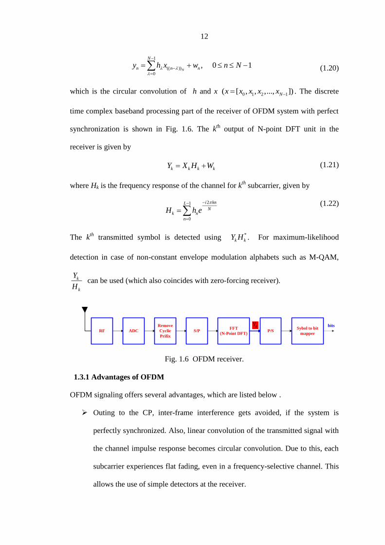
which is the circular convolution of h and x 0 1 2 1( [ , , ,..., ])Nx x x x x . The discrete
time complex baseband processing part of the receiver of OFDM system with perfect
synchronization is shown in Fig. 1.6. The kth
output of N-point DFT unit in the
receiver is given by
k k k kY X H W (1.21)
where Hk is the frequency response of the channel for kth
subcarrier, given by
21
0
i knL
Nk n
n
H h e
(1.22)
The kth
transmitted symbol is detected using *
k kY H . For maximum-likelihood
detection in case of non-constant envelope modulation alphabets such as M-QAM,
k
k
Y
H can be used (which also coincides with zero-forcing receiver).
FFT
(N-Point DFT)
Remove
Cyclic
Prifix
ADCRF S/P P/SSybol to bit
mapper
bitskY
Fig. 1.6 OFDM receiver.
1.3.1 Advantages of OFDM
OFDM signaling offers several advantages, which are listed below .
Outing to the CP, inter-frame interference gets avoided, if the system is
perfectly synchronized. Also, linear convolution of the transmitted signal with
the channel impulse response becomes circular convolution. Due to this, each
subcarrier experiences flat fading, even in a frequency-selective channel. This
allows the use of simple detectors at the receiver.
13
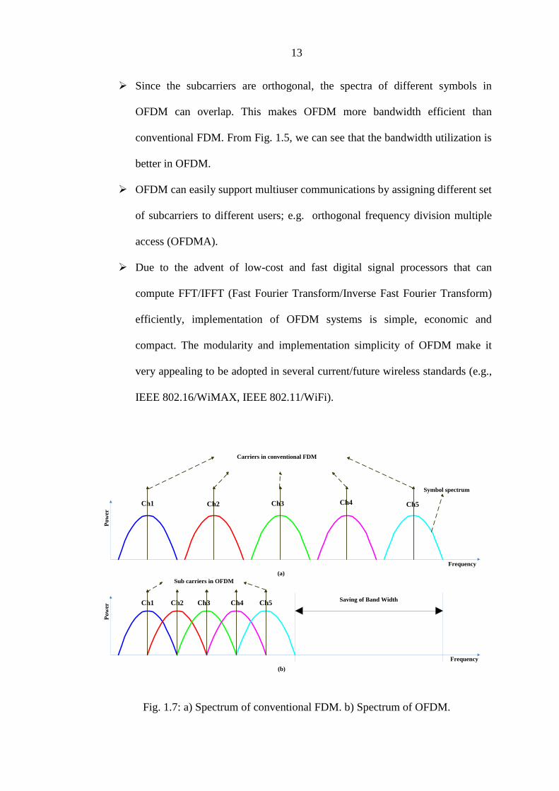
Since the subcarriers are orthogonal, the spectra of different symbols in
OFDM can overlap. This makes OFDM more bandwidth efficient than
conventional FDM. From Fig. 1.5, we can see that the bandwidth utilization is
better in OFDM.
OFDM can easily support multiuser communications by assigning different set
of subcarriers to different users; e.g. orthogonal frequency division multiple
access (OFDMA).
Due to the advent of low-cost and fast digital signal processors that can
compute FFT/IFFT (Fast Fourier Transform/Inverse Fast Fourier Transform)
efficiently, implementation of OFDM systems is simple, economic and
compact. The modularity and implementation simplicity of OFDM make it
very appealing to be adopted in several current/future wireless standards (e.g.,
IEEE 802.16/WiMAX, IEEE 802.11/WiFi).
Ch1 Ch2 Ch3 Ch4 Ch5
Ch1 Ch2 Ch3 Ch4 Ch5Saving of Band Width
Frequency
Frequency
Po
wer
Po
wer
(a)
(b)
Carriers in conventional FDM
Symbol spectrum
Sub carriers in OFDM
Fig. 1.7: a) Spectrum of conventional FDM. b) Spectrum of OFDM.

14
1.3.2 Issues in OFDM
Uncoded OFDM fails to provide any form of diversity. To achieve diversity,
either outer coding or other forms of precoding needs to be performed.
OFDM is sensitive to errors in carrier frequency synchronization. The
difference between the frequency of the transmitted carrier and the recovered
carrier at the receiver is called Carrier Frequency Offset (CFO). Non-zero
CFO introduces Inter Carrier Interference (ICI) due to the loss of
orthogonality of the subcarriers, which, in turn, degrades the bit error rate
(BER) performance of the system. To avoid this, use of accurate carrier
frequency estimation and tracking techniques are needed. In the absence of
tight carrier frequency tracking (e.g., when CFOs are large), ICI cancellation
techniques can be employed at the receiver to improve performance.
OFDM is also sensitive to timing synchronization errors. The amount of
misalignment of the processing window with respect to the processing window
with perfect timing is called the Timing Offset (TO). Non-zero TOs cause
interference from samples of the adjacent frame and the symbols of the current
frame due to loss of orthogonality among the subcarriers. This degrades the
BER performance of the system. Interference cancellation techniques can be
employed at the receiver to improve performance when TOs are large.
High peak-to-average power ratio (PAPR) is an issue in OFDM [13]. This
reduces the power efficiency of the amplifier. To increase the efficiency of the
amplifier, sophisticated techniques are needed to reduce the PAPR.
OFDM incurs a throughput penalty in frequency domain due to the use of
guard subcarriers and a throughput penalty in time-domain due to the use of
CP.
15
1.4 MIMO TECHNOLOGY
One major breakthrough in wireless communications is the invention of the
systems with multiple antennas at the transmitters and the receivers, [14] called
multiple-input multiple-output (MIMO) system, which could show considerable
increase in the channel capacity. In a multipath wireless channel environment, the
deployment of MIMO systems which enhances the channel capacity enormously has
led to the achievement of high rate data transmission without increasing the total
transmission power or bandwidth. Using multiple antennas at both the source
(transmitter(TX)) and the destination (receiver(RX)) is referred to as spatial
multiplexing [15]. The use of MIMO in wireless systems has several advantages such
as
Significant increase in data throughput and spectral efficiency
Reduced fading because of antenna diversity
Increased user capacity
Greater immunity to interference
MIMO combined with OFDM provides significant improvement in the performance
of wireless LANs, enabling them to serve existing applications more cost-effectively,
as well as making new and more demanding applications possible [16].
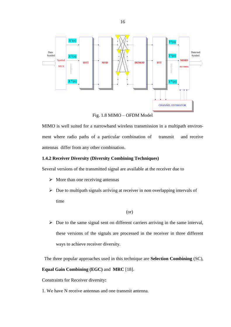
1.4.1 MIMO- OFDM
The spectral efficiency of MIMO is achieved by transmitting different symbols on
different transmit antennas simultaneously as shown in Fig. 1.8, in such a way that the
information can be recovered from the parallel streams of data arriving at different
antennas in the receiver under suitable channel conditions (i.e. sufficiently rich
multipath scattering). This requires of advanced signal processing algorithms, which
also ensures adequate BER performance [17].
16
Spatial
MUX
IFFTMIMO
DECODING
FFTMOD DEMOD
CHANNEL ESTIMATOR
------------------------------
- --------------------------------------------------------------------------------------------------------
----
----
----
----
----
---
--------
-------
----------------------------------------------------------------
Data
Symbol
Detected
Symbol
. . . . . . . . .
. . . . . . . . .
1( )X n
2( )X n
( )NX n
1( )Y n
2( )Y n
( )NY n
Fig. 1.8 MIMO – OFDM Model
MIMO is well suited for a narrowband wireless transmission in a multipath environ-
ment where radio paths of a particular combination of transmit and receive
antennas differ from any other combination.
1.4.2 Receiver Diversity (Diversity Combining Techniques)
Several versions of the transmitted signal are available at the receiver due to
More than one receiving antennas
Due to multipath signals arriving at receiver in non overlapping intervals of
time
(or)
Due to the same signal sent on different carriers arriving in the same interval,
these versions of the signals are processed in the receiver in three different
ways to achieve receiver diversity.
The three popular approaches used in this technique are Selection Combining (SC),
Equal Gain Combining (EGC) and MRC [18].
Constraints for Receiver diversity:
1. We have N receive antennas and one transmit antenna.
17
2. The channel is flat fading – In simple terms, it means that the multipath channel has
only one tap. So, the convolution operation reduces to a simple multiplication.
3. The channel experienced by each receiving antenna is randomly varying in time.
For the thi receiving antenna, each transmitted symbol gets multiplied by a randomly
varying complex number ih . As the channel under consideration is a Rayleigh
channel, the real and imaginary parts of ih are Gaussian distributed having mean 0
and variance 1/2.
4. The channel experienced by each receive antenna is independent from the channel
experienced by other receive antennas.
5. On each receive antenna, the noise w has the Gaussian probability density function.
The noise on each receive antenna is independent from the noise on the other receive
antennas.
6. At each receive antenna, the channel ih is known at the receiver. For example, on
the thi receive antenna, equalization is performed at the receiver by dividing the
received symbol iy by the apriori known ih i.e.
ˆ i i ii
i i
y h x wy x w
h h
(1.23)
where ii
i
ww
h is the additive noise scaled by the channel coefficient.
7. In the presence of channel ih , the instantaneous bit energy to noise ratio at thi
receive antenna is
2
0
i b
i
h E
N .
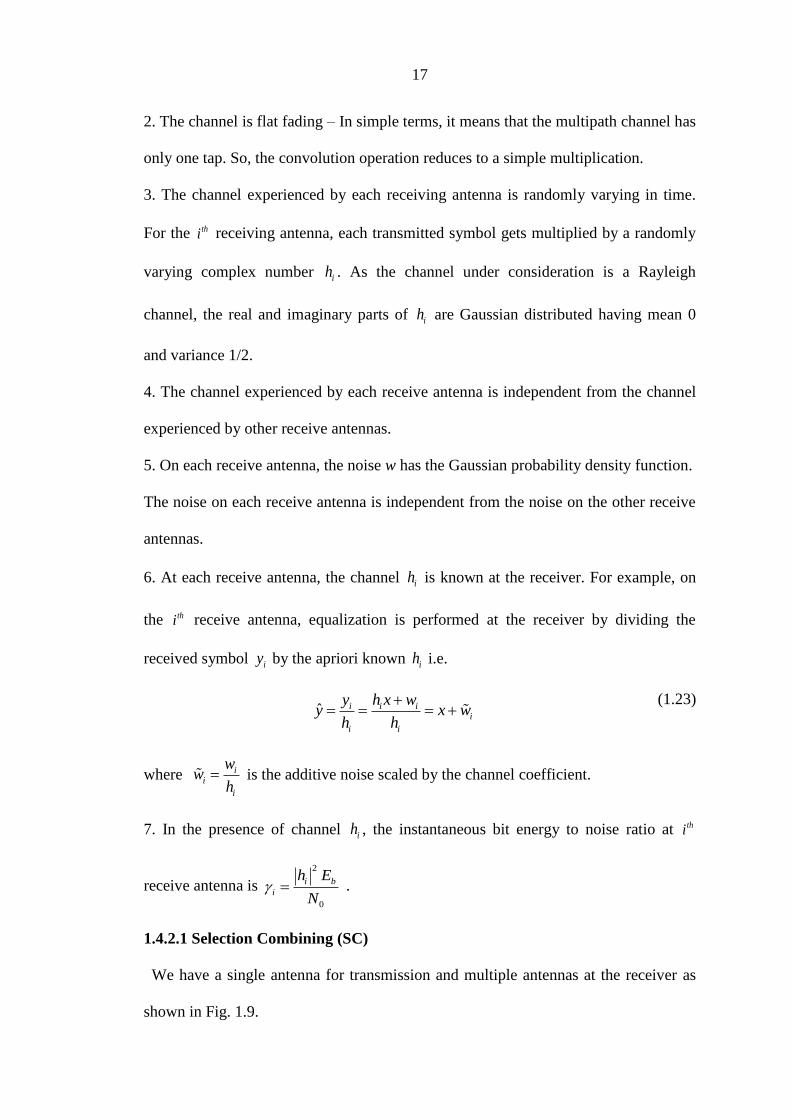
1.4.2.1 Selection Combining (SC)
We have a single antenna for transmission and multiple antennas at the receiver as
shown in Fig. 1.9.
18
Transmitter
Receiver
1
2
N
1h
2h
Nh
Fig. 1.9 Receive diversity in a wireless link
At the receiver we have now N copies of the same transmitted symbol.
Selection combining is the approach in which the receiver selects the signals of
highest energy among the received signal set and combines them and gives the sum to
the detector. In the presence of channel ih , the instantaneous bit energy to noise ratio
at thi receive antenna is
2
0
i b
i
h E
N . The chosen received signals are the ones with
max ( )i
i
.
Bit Error probability with selection diversity
Bit energy to noise ratio of 0
bE
N , the BER for BPSK in AWGN is given as
0
1
2
bb
Ep erfc
N
(1.24)
Given that the effective bit energy to noise ratio with selection diversity is , the total
BER is given as
19
1/2
0 0
11 1
2 /
Nk
e
k b
N kp
k E N
(1.25)
1.4.2.2 Equal Gain Combining (EGC)
This is the combining technique in which the phase equalized versions of the
individual signals are added and given as the input to the detector. If the phase of the
channel coefficient in the thi received signal iy is i , the input to the detector is
ˆi
i
i
i
ji
j
i i
ji
i i
i
yy
e
h e x w
e
h x w
(1.26)
where, i
ii j
ww
e
is the additive noise scaled by the phase of the channel coefficient.
BER with EGC
With two copies of the signal , the BER with EGC is [19] ,
0 0
0
21
12
1
b b
eb
E E
N Np
E
N
(1.27)
1.4.2.3 Maximal Ratio Combining (MRC)
If the thi received signal is, i i iy h x w , this is the combining technique in which the
input to the detector is
*
21
Ni i
i i
h yy
h
(1.28)
where, iy is the received symbol on the thi receive antenna, ih is the channel on the thi
receive antenna.

20
Error rate with MRC
If ih is a Rayleigh distributed random variable, then 2
ih is a chi-squared random
variable with two degrees of freedom.
Since the effective bit energy to noise ratio is the sum of N such random variables,
the PDF of is a chi-square random variable with 2 N degrees of freedom.
The total BER is given by
1
0
1/2
0
11
1 1 11
2 2 /
NkN
e
k
bwhere
N kp p p
k
pE N
(1.29)
When a wideband wireless transmission is preferred in order to achieve a higher data
rate, the use of orthogonal frequency division multiplexing (OFDM) allows creation
of many narrowband parallel frequency channels, each of which can be sent using
MIMO system. Hence, MIMO-OFDM is currently being considered as a strong
method for the physical layer transmission scheme of next generation wireless
communication systems [20].
1.5 MIMO-OFDM SYSTEMS
1.5.1 Introduction
MIMO systems have become popular since Alamouti introduced the well known
Space-Time Block Codes (STBC) [21], which consist of data coded through space
and time to improve the reliability of the transmission, as redundant copies of the
original data are sent over independent fading channels [22].
In addition to spatial diversity provided by multiple antennas and temporal diversity
provided by the same symbols being transmitted in different time slots, the
combination of MIMO-OFDM offers a third dimension of coding which achieves
21
frequency diversity known as Space-Frequency Block Coding (SFBC), which is
respectively capable of achieving two dimensional coding over space and frequency
as proposed in the literature [20]. Coding through space and frequency dimension
also offers implementation advantages [23]. However, for frequency-selective fading
channels, by combining OFDM with MIMO referred to as MIMO-OFDM
guarantees full diversity, Nt x Nr, the product of number of transmitting and
receiving antennas.
Furthermore, STBC and SFBC are limited to quasi-static fading channels.
Considering a general block-fading channel, where the channel coefficients are
constant within one block but are independent from block to block, none of the
existing coding schemes under such condition can achieve full diversity.
The combination of STBC with OFDM, termed „STBC-OFDM‟ was first proposed by
Agrawal in [24]. Following this development, various researchers have focused on
designing the system for scenarios where the channel is assumed to be known at the
receiver. For example, the designs proposed in [21][25][165]. The results from these
works are consistent with the findings in [26][122] indicate that the combination of
MIMO techniques with OFDM improves the transmission rate, range and reliability.
Frequency diversity can be achieved by combining MIMO with OFDM and using
the codes known as SFBC resulting in SFBC-OFDM which exploits the maximum
diversity available in MIMO channels [27]. In STBC-OFDM, the information
symbols are coded across multiple antennas and time via the use of multiple
consecutive OFDM symbols [28], whereas, SFBC symbols are coded across multiple
antennas and multiple OFDM subcarriers.
The combination of MIMO-OFDM shows the ability to enable data transmission at
higher rate over multipath and frequency selective fading channels. The additional
22
advantages of STBC-OFDM are the simple linear decoding and low complexity
receiver which have made them a popular choice for future wireless communications.
Similarly SFBC is a bandwidth efficient technique, with low computational
complexity providing transmit diversity gain for OFDM-systems [29].
1.6 MIMO-STBC-OFDM
1.6.1 STBC with Alamouti Code
This is a popular transmit diversity scheme that uses Alamouti STBC [30]. This is
the coding scheme that works when the channel is a flat fading Rayleigh channel. To
achieve the receive diversity we need two antennas at the receiver and the received
signals are processed using the – SC, ECG or MRC.
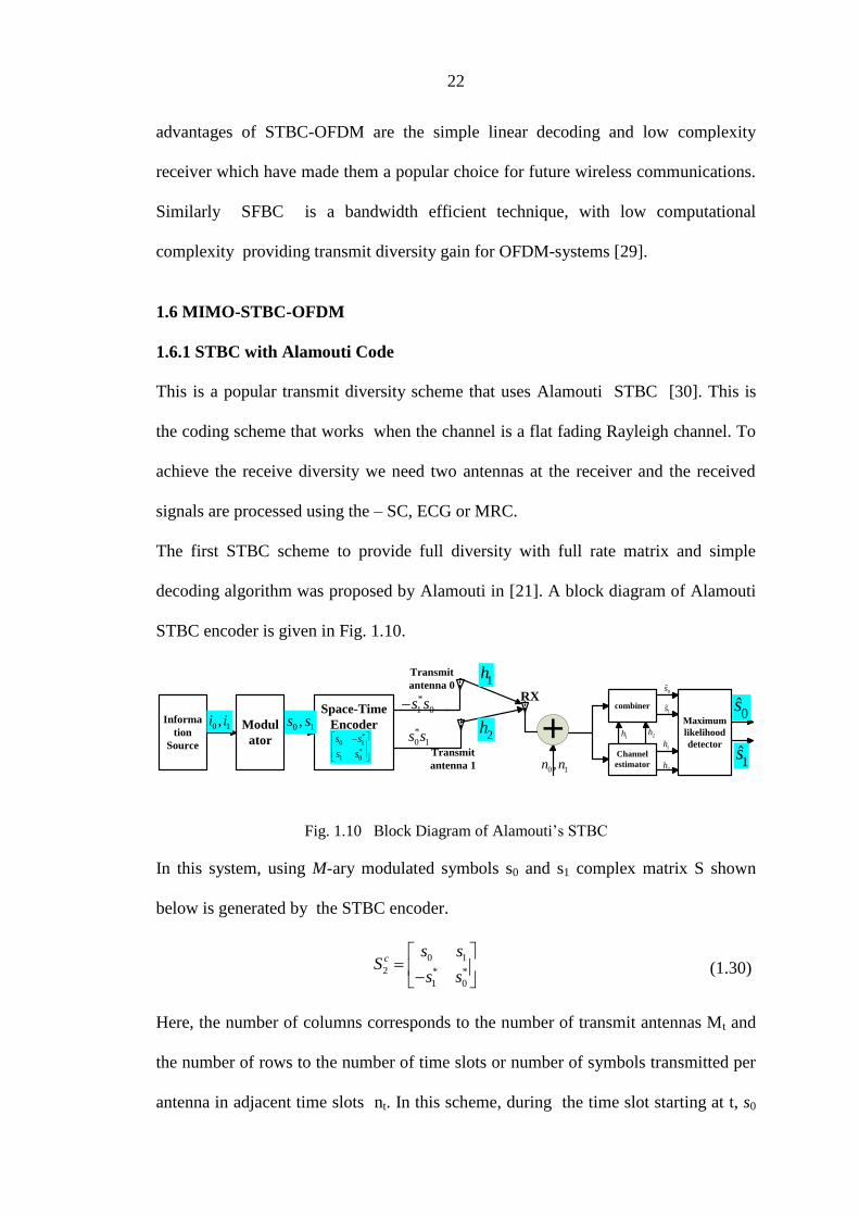
The first STBC scheme to provide full diversity with full rate matrix and simple
decoding algorithm was proposed by Alamouti in [21]. A block diagram of Alamouti
STBC encoder is given in Fig. 1.10.
Space-Time
EncoderModul
ator
Informa
tion
Source*
0 1
*1 0
s s
s s
0 1,i i*
0 1s s0 1,s s
*
1 0s s
Transmit
antenna 0
Transmit
antenna 1
RXcombiner
Channel
estimator
Maximum
likelihood
detector
0 1,n n
1h 2h
1h
2h
0̂s
0s
1s
1̂s
1h
2h +
Fig. 1.10 Block Diagram of Alamouti‟s STBC
In this system, using M-ary modulated symbols s0 and s1 complex matrix S shown
below is generated by the STBC encoder.
0 1
2 * *
1 0
cs s
Ss s
(1.30)
Here, the number of columns corresponds to the number of transmit antennas Mt and
the number of rows to the number of time slots or number of symbols transmitted per
antenna in adjacent time slots nt. In this scheme, during the time slot starting at t, s0
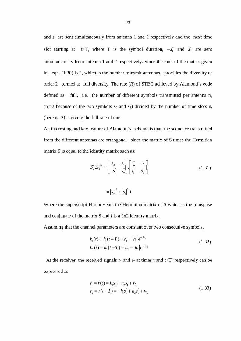
23
and s1 are sent simultaneously from antenna 1 and 2 respectively and the next time
slot starting at t+T, where T is the symbol duration, *
1s and *
0s are sent
simultaneously from antenna 1 and 2 respectively. Since the rank of the matrix given
in eqn. (1.30) is 2, which is the number transmit antennas provides the diversity of
order 2 termed as full diversity. The rate (R) of STBC achieved by Alamouti‟s code
defined as full, i.e. the number of different symbols transmitted per antenna ns
(ns=2 because of the two symbols s0 and s1) divided by the number of time slots nt
(here nt=2) is giving the full rate of one.
An interesting and key feature of Alamouti‟s scheme is that, the sequence transmitted
from the different antennas are orthogonal , since the matrix of S times the Hermitian
matrix S is equal to the identity matrix such as:
*0 1 0 1
2 2 * * *1 0 1 0
. .c cHs s s s
S Ss s s s
2 2
0 1s s I
(1.31)
Where the superscript H represents the Hermitian matrix of S which is the transpose
and conjugate of the matrix S and I is a 2x2 identity matrix.
Assuming that the channel parameters are constant over two consecutive symbols,
1
2
1 1 1 1
2 2 2 2
( ) ( )
( ) ( )
j
j
h t h t T h h e
h t h t T h h e
(1.32)
At the receiver, the received signals r1 and r2 at times t and t+T respectively can be
expressed as
1 1 0 2 1 1
* *
2 1 1 2 0 2
( )
( )
r r t h s h s w
r r t T h s h s w
(1.33)

24
where w1 and w2 represent the white Gaussian noise samples. The transmitted
symbols s0 and s1 can be recovered by combining the received signals r1 and r2 as:
2 2* * * *
0 1 1 2 2 1 2 0 1 1 2 2
2 2* * * *
1 2 1 1 2 1 2 1 1 2 2 1
s r h r h h h s h w h w
s h r h r h h s h w h w
(1.34)
As it can be seen from eqn. (1.33) and (1.34), and due to the orthogonality of the
transmitted matrix, cancellation of the unwanted signal s1 to recover s0 and s0 to
recover s1 is possible. Both signals are then passed through the ML detector as
described in Fig. 1.8 to determine the most likely transmitted symbols.
The decision rule is based on choosing si if and only if:
2 ~ ~22 2 2 2 2 2
1 2 0 1 2 01 , 1 ,i i k kh h s d s s h h s d s s (1.35)
From eqn. (20), it can be seen that the transmitted symbol is the one with minimum
Euclidean distance from the combined output signal.
1.6.2 Generalized STBC
STBC is regarded as the generalization of the Alamouti coding. Tarokh et al
generalized STBC to an arbitrary number of transmit and receive antennas in [28].
STBC can achieve full rate and full diversity which as stated earlier is specified by the
number of different symbols to transmit and the number of time slots required to
transmit the entire STBC block. In addition, STBC allows very simple decoding
algorithm based on the ML decoding described in the previous Subsection.
1,1hTX1
STBC
encoder
Information
SourceModulator
0 1, ,... nsi i i 0 1
, ,... nss s sSTBC
decoder
RX1
,
DemodulatorsnTX
snRX
1, Nh
,1Mh
,M Nh
0 1, ,... nss s s
0 1, ,... nsi i i
Fig. 1.11 Block Diagram of generalized STBC

25
Fig. 1.11 shows a block diagram of the generalized STBC communication link. Like
Alamouti‟s case, data is first mapped by a 2k points modulator resulting in ns data
symbols passed to the STBC encoder. At the receiver, the data is decoded with the
STBC decoder that contains channel estimator, combiner and ML detector. Based on
the type of modulation used, STBC uses either real or complex constellation. STBC
with real constellation is Pulse Amplitude Modulation (PAM) or Binary Phase Shift
Keying (BPSK) signal, and with complex-constellation is M-PSK or M-QAM
signal.
1.6.2.1 STBC for Real -Constellations
The real transmission matrices for two transmit antennas are given by:
0 1
2
1 0
s sS
s s
(1.36)
At the receiver side, the received equations are based on Alamouti‟s model with the
simplicity of having only real symbols and therefore no conjugation in the equations
[28]. Thus, the received equations for two transmit antennas is given as
1, 1, 0 2, 1 1,
2, 1, 1 2, 0 2,
( )
( )
j j j j j
j j j j j
r r t h s h s w
r r t T h s h s w
(1.37)
where w1,j, w2,j are independent noise samples and j denotes the j th
receiving antenna.
Received signals are then combined at the combiner as given by
0
1
~
1, 1, 2, 2,
1
~
1, 2, 2, 1,
1
r
r
N
j j j j
j
N
j j j j
j
s r h r h
s r h r h
(1.38)
1.6.2.2 STBC for Complex-Constellations
The OFDM symbol n and n+1 provided by the following equations [1.39] [1.40]

26
1 0 1 2 2 4 2 2, ,...., ,...., , T
k Ns NsS n s s s s s
2 1 3 2 1 2 3 2 1, ,..., ,..., , T
k Ns NsS n s s s s s
(1.39)
* * * * * *
1 1 3 2 1 2 3 2 1 21 , ,..., ,..., ,T
k Ns NsS n s s s s s S n
* * * * * *
2 0 2 2 2 4 2 2 11 , ,..., ,..., ,T
k Ns NsS n s s s s s S n
(1.40)
with k=0, 1, …, Ns-1 and n represent the n th
OFDM symbol.
At OFDM symbol n, 2ks and 2 1ks are transmitted simultaneously at subcarrier k
from antenna 1 and 2 respectively and in the second OFDM symbol n+1,*2 1ks
and
*2ks are transmitted simultaneously at the same subcarrier k from antenna 1 and 2
respectively.
At the receiver, the signal is first demodulated by an FFT demodulator and data is
recovered by the space-time decoder. For an ideal transmission where the channel is
known at the receiver and according to the equations given in [21] for single carrier
system, estimation of symbols is done using the following equations:
1,
~
1, , , 2, , ,
1
1r
k
N
j k j k j k j k
j
S n H n R n H n R n
2
~* *
1, , ,2 2, , ,2 1k j k j k j k j ks h r h r
2,
~* *
2, , , 1, , ,
1
1r
k
N
j k j k j k j k
j
S n H n R n H n R n
2 1
~* *
2, , ,2 1, , ,2 1
1
r
k
N
j k j k j k j k
j
s h r h r
(1.41)

27
where k=1, 2, ...,Ns, representing the symbol number, j represent the j th receive antenna
and ,i ks , 2ks and 2 1ks are the decoded signal and symbols respectively.
Finally, the combined signals are sent to the ML detection in order to recover the
transmitted signal.
1.6.3 Conclusions
STBC is a coding technique used to enhance the capacity of wireless communication
systems without affecting the bandwidth efficiency. STBC provides Low complexity,
full diversity scheme or technique that provides full rate only for the case of two
transmits antennas. The disadvantage of this scheme is that the decoding complexity
grows linearly with the number of transmit and receive antennas. If the channel is
frequency selective and the code used is the one developed for the flat fading channel,
the spectrum efficiency is increased by following a two different approaches. First
is to cancel the effect of ISI by converting frequency selective channels into non-
frequency selective channels. Second is designing STBC encoder and decoder
employed to be adaptive to non-frequency selective channels. One of the first
methods proposed by researchers to combat the effect of ISI uses equalizers at the
receiver to convert the channel into a temporal ISI-free channel [32]. Another
approach proposed in [33] achieved lower decoding complexity at the receiver. The
concept exploits one of the properties of OFDM which converts frequency selective
channels into multiple parallel flat fading channels.
Due to the promising performances achieved by STBC in wireless communications,
many wireless standards such as IEEE802.11n, IEEE802.16 and LTE are now
incorporating these coding ideas. Current research is mainly focused on the use of
STBC with OFDM in frequency selective environment.

28
1.6.4 Issues in MIMO-STBC-OFDM
To ensure an ISI free MIMO-OFDM system , the guard interval (GI) length must be
longer than any maximum propagation delay of a sub-channel link from a transmit
antenna to a receive antenna. It is difficult to meet this condition, since the GI length
is a system parameter which is assigned by the transmitter, whereas the maximum
propagation delay is a parameter of the channel, which depends on the transmission
environment [34]. If the receiver moves from one propagation environment to
another, then the GI length condition may no longer be fulfilled. In such cases, the
performance of the system gets degraded due to ISI and ICI.
1.7 MIMO-SFBC-OFDM
1.7.1 SFBC-OFDM
SFBC-OFDM with two transmit antennas transmits the matrix 2
cS (1.30) in two
different subcarriers. Here only one OFDM symbol is required as data is coded across
subcarriers. Symbol ks and *
1ks are transmitted one by one from antenna 1 while 1ks
and *
ks are transmitted in a similar way from antenna 2 is shown in Fig. 1.11.
The encoding and transmission scheme for Alamouti‟s SFBC scheme for two
transmit antennas is shown in Table 1.1 [14] [27].
Symbol transmitted
on antenna (1)
Symbol transmitted
on antenna (2)
Subcarrier, k sk sk+1
Subcarrier, k+1 -sk+1*
sk*
Table 1.1 Encoding and transmission scheme for Alamouti‟s SFBC with two transmit
antennas
29
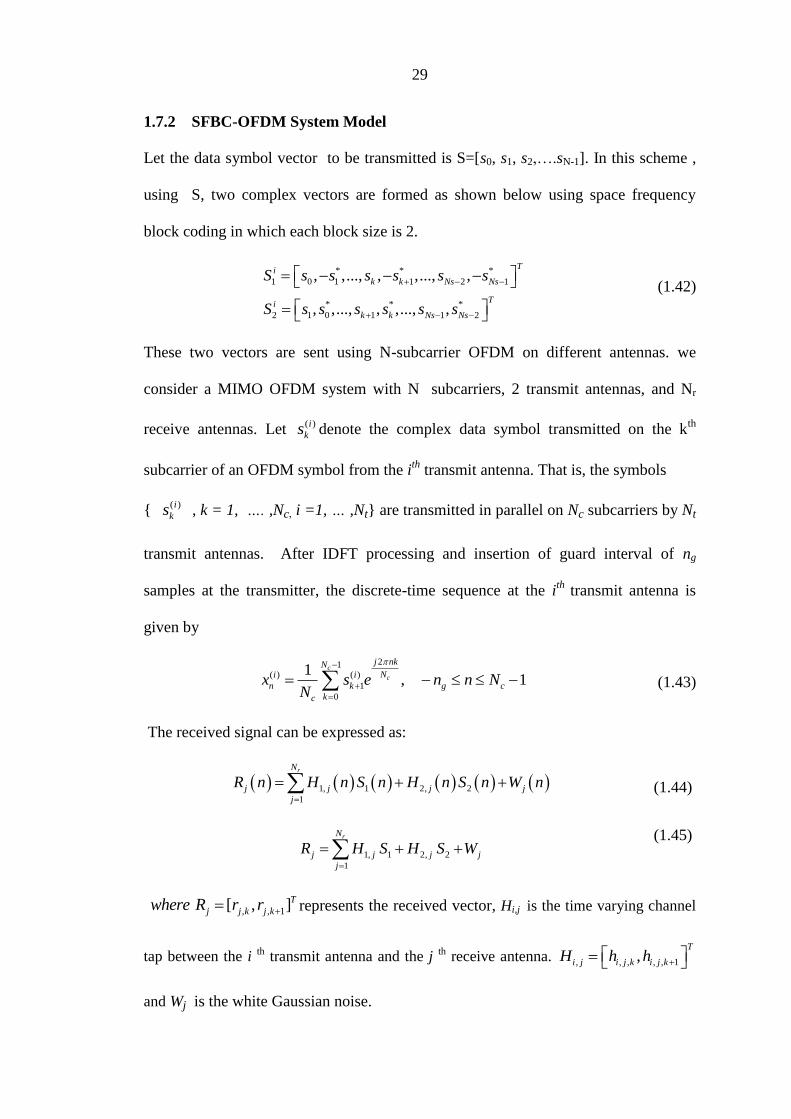
1.7.2 SFBC-OFDM System Model
Let the data symbol vector to be transmitted is S=[s0, s1, s2,….sN-1]. In this scheme ,
using S, two complex vectors are formed as shown below using space frequency
block coding in which each block size is 2.
* * *
1 0 1 1 2 1
* * *
2 1 0 1 1 2
, ,..., , ,..., ,
, ,..., , ,..., ,
Ti
k k Ns Ns
Ti
k k Ns Ns
S s s s s s s
S s s s s s s
(1.42)
These two vectors are sent using N-subcarrier OFDM on different antennas. we
consider a MIMO OFDM system with N subcarriers, 2 transmit antennas, and Nr
receive antennas. Let ( )i
ks denote the complex data symbol transmitted on the kth
subcarrier of an OFDM symbol from the ith
transmit antenna. That is, the symbols
{ ( )i
ks , k = 1, …. ,Nc, i =1, … ,Nt} are transmitted in parallel on Nc subcarriers by Nt
transmit antennas. After IDFT processing and insertion of guard interval of ng
samples at the transmitter, the discrete-time sequence at the ith
transmit antenna is
given by
21( ) ( )
1
0
1, 1
c
c
j nkNNi i
n k g c
kc
x s e n n NN
(1.43)
The received signal can be expressed as:
1, 1 2, 2
1
rN
j j j j
j
R n H n S n H n S n W n
(1.44)
1, 1 2, 2
1
rN
j j j j
j
R H S H S W
(1.45)
, , 1[ , ]T
j j k j kwhere R r r represents the received vector, Hi,j is the time varying channel
tap between the i th transmit antenna and the j th receive antenna. , , , , , 1,
T
i j i j k i j kH h h
and Wj is the white Gaussian noise.
30
In this transmission, the channel parameters remain constant over two consecutive
subcarriers and the channel parameters are known at the receiver. At the receiver, the
vector y of the received signal is formed according to the equation, *
, , 1, .Tj k j ky r r
After FFT operation is performed, the received data is sent to the SFBC decoder, and
estimation of symbols is done using the following equations:
1
~* *
1, , , 2, , , 1
1
~* *
2, , , 1, , , 1
1
( )
r
k
r
k
N
j k j k j k j k
j
N
j k j k j k j k
j
s h r h r
s h r h r
(1.46)
Data is then sent to the ML decoder and to the demapper to recover the transmitted
stream. It is a bandwidth efficient technique with low computational complexity that
provides transmit diversity [30]. The main advantage with Alamouti‟s transmit
diversity scheme is simple combining required at the receiver [21] [35].
If the channel is highly frequency selective or varies during the symbol transmission
the performance of the system gets affected seviourly.
1.7.3 Conclusion
The equations of SFBC-OFDM are similar to the equations given for STBC-OFDM,
the difference being that symbols are coded through frequency instead of time for
the former. As for single carrier systems, complexity increases linearly with the
number of transmit and receive antennas.
Space Frequency Coding (SFC) techniques are used to improve the performance of
MIMO systems. Their central issue is the exploitation of multipath effects in order to
achieve very high spectral efficiencies. With this purpose, the aim of the space
frequency coding lies in the design of two-dimensional signal matrices to be
transmitted in a specified frequency slot on a number of antennas. Thus, it introduces
31
redundancy in space through the addition of multiple antennas and redundancy in
frequency through channel coding provide diversity in the spatial dimension, as well
as coding gain. Therefore, the transmit diversity plays an integral role in the SFC
design.
1.7.4 Issues in MIMO-SFBC-OFDM
A SFBC-OFDM using Alamouti‟s code in the frequency dimension is defined in
[36] for high mobility broadband wireless access. For the time dimension STBCs to
be single symbol decodable, the often made „quasi-static‟ (QS) assumption is
essential, the violation of which results in an error-floor. Rapid time-variations in the
fading process result in such a violation. In SFBC-OFDM systems, the QS assumption
gets violated in the frequency dimension in highly frequency-selective channels (i.e.,
different subcarriers, and hence symbols belonging to the same SFBC block mounted
on different subcarriers), even if time-variations in the fading process is very slow.
The severity of this effect depends on the channel length L, power delay profile of the
channel, and size of the SFBC block. In highly frequency-selective channels (i.e.,
large L), this QS assumption violation becomes a source of significant inter-symbol
interference (ISI) in the frequency dimension in SFBC-OFDM.
Further, in any OFDM system, the orthogonality among subcarriers is lost if the
channel changes within an OFDM symbol duration, which results in ICI [37]. Thus,
in addition to the issue of ISI caused due to frequency-selectivity of the channel,
SFBC-OFDM experiences ICI caused due to time selectivity of the channel (i.e.,
channel varying within one OFDM symbol duration) [38]. Attempts have been made
in the literature to cancel ICI in MIMO-OFDM systems.
MIMO-OFDM has already been adopted by several standards such as IEEE 802.11n,
IEEE802.16a and 3GPP [39] [40] [25]. However, in both STBC-OFDM and SFBC-
32
OFDM, channel parameters need to be known at the receiver to recover the
transmitted symbols. Therefore, channel estimation with acceptable level of accuracy
and hardware complexity has become an important research topic for MIMO-OFDM
systems.
1.8 LITERATURE REVIEW
Cooley J.W. et al in [41] proposed whatever may be the case, especially with the
help of Fourier transform the complexity of the OFDM system will be removed
initially. Inverse Fourier transforms are utilized to execute OFDM systems. The
Fourier transform is used to divide or decompose a waveform or function into
sinusoids of various frequencies which will be aggregate with the original waveform.
OFDM started in the mid 60‟s, Chang in [42], proposed a method to synthesise band
limited signals for multichannel transmission. The idea is to transmit signals
simultaneously through a linear band limited channel without ICI and ISI.
Saltzberg in [43], performed an analysis based on Chang‟s [42] work and presented
a method to reduce the crosstalk between adjacent channels rather than on perfecting
the individual signals.
Benedict et al in [44], provides some basic theory about estimating noise in
narrowband AWGN systems.
Johnson, S.G. in [45], revealed that the waveforms of OFDM time domain are
selected in such a way that mutual orthogonality will be existed even with the
subcarrierswith overlapping spectra. In relation with the OFDM, it is described that
among all the carriers in the collection, orthogonality is an identification of a definite

33
and the fixed relationship. Each carrier is placed in such a way that it will appear at
the point of zero energy frequency of all the remaining carriers.
In 1971, Weinstein and Ebert in [46], made an important contribution to OFDM.
Discrete Fourier transform (DFT) method was proposed to perform the baseband
modulation and demodulation. DFT is an efficient signal processing algorithm. It
eliminates the banks of subcarrier oscillators. They used guard space between
symbols to combat ICI and ISI problem. This system did not provide perfect
orthogonality between subcarriers over a dispersive channel. Weinstein and Ebert
applied the DFT and IDFT to parallel data transmission system as part of the
modulation and demodulation processes. In the 1980s, OFDM has been studied for
high-speed modems, digital mobile communications and high-density recording [47].
Peled and Ruiz in [47], introduced CP that solved the orthogonality issue. They
filled the guard space with a cyclic extension of the OFDM symbol. It is assumed that
the CP is longer than impulse response of the channel.
Publication of the research papers on OFDM is quite common after 1990. Particularly
the offset estimation and interference mitigation techniques and later the publication
rate are doubled every year.
Cox. D.C. et al in [48], presented that an integer number of cycles are contained by
the each carrier over an each period of symbol in the carrier orthogonality. This is
caused because each carrier of the spectrum will contain null and at the center
frequency of each carrier and every remaining carriers in the system. In between the
carriers, interference will not be occurred and it allows the carriers to be closely
spacing together. Spacing is needed in frequency division multiple access (FDMA) to

34
avoid the problem of overhead carrier. The signal carrier in the OFDM consists of a
narrow bandwidth of 1 kilohertz (KHz) so that it results in low symbol rate. This is
due to high tolerance which took place in the signal to the multipath delay spread. The
delay spread should be very far to cause significant ISI.
Cimini in [49] and Kelet in [50], published analytical and early seminar experimental
results on the performance of OFDM modems in mobile communications.
Moose. P. in [51], revealed the OFDM applications were not ideal in 1960's, this is
because at the point of time, to produce carrier frequencies, various banks of the
oscillators are required and those are essential for the transmission of sub-channel. It
is difficult to prove and overcome at that time of period. This system is not considered
because it is not executed.
J. J. van de Beek et al in [52], proposed a frame synchronization algorithm using the
repetition in the OFDM symbol due to the CP. This is expanded in [53] to estimate
the frequency offset. The limits of the use of the CP for synchronization are given in
[54]. The use of the virtual subcarriers for the synchronization of an OFDM system is
proposed in [55].
J. J. van de Beek et al in [56], proposed the linear minimum mean square error
(LMMSE) channel estimation method based on channel autocorrelation matrix in
frequency domain . To reduce the computational complexity of LMMSE estimation, a
low-rank approximation to LMMSE estimation has been proposed by singular value
decomposition . The drawback of LMMSE channel estimation is that it requires the
knowledge of channel autocorrelation matrix in frequency domain and the signal to
noise ratio (SNR). Though the system can be designed for fixed SNR and channel
35
frequency autocorrelation matrix, the performance of the OFDM system gets
degraded significantly due to the mismatch of estimated parameters with system
parameters.
O. Edfors et al in [57], analyzed the performance of low complexity estimators based
on DFT. In [58], block and comb type pilot arrangements have been analyzed.
Schmidl et al.in [59], present a time domain approach for synchronizing transmitter
and receiver. As a by-product they suggest an SNR estimator working in the time
domain. This estimator works well for the SNR below 20 dB. Above this level, an
accurate estimate of the SNR cannot be determined.
T. K. Moon in [60], proposed expectation maximization (EM) algorithm was
proposed, and in [61], EM algorithm was applied on OFDM systems for efficient
detection of transmitted data as well as for estimating the channel impulse response.
Here, ML estimate of channel was obtained by using channel statistics via the EM
algorithm.
Lee, D. et al in [62], described OFDM as another form of Multi Carrier Modulation
(MCM). Multi Carrier Modulation (MCM) is known as the process of transmitting
data by separating the stream in to various bit streams. Every bit stream contains a
lower bit rate. The closely spaced subcarriers with overlapping spectra are the feature
of this.
M. Julia Fernandez et al in [63], proposed a very good approach for OFDM symbol
synchronization in which synchronization (correction of frequency offsets) is
achieved simply by using pilot carriers already inserted for channel estimation, So no
36
extra burden is added in the system for the correction of frequency offsets. Similarly
in [64], it has been shown that the number of pilot symbols for a desired BER and
Doppler frequency are highly dependent on the pilot patterns used, So by choosing a
suitable pilot pattern, we can reduce the number of pilot symbols, but still retaining
the same performance. Most common pilot patterns used in literature are block and
comb-type pilot arrangements. Comb patterns perform much better than block
patterns in fast varying environments [65].
One of the milestone references works in this area was published by Simon and
Alouini [66], where the performance of a number of digital communication systems
under different fading conditions was analyzed following a common strategy. Most of
the results provided in this paper allowed obtaining the SER in exact closed-form,
whereas in other cases, a numerical integration was necessary [67].
The analytical performance of most of wireless communication systems under
different fading conditions has already been accomplished when perfect channel state
information (CSI) is assumed to be known at the RX side (or even at the TX side, if
required) [68] [69]. Hence these results hence are useful to determine the maximum
achievable performance of these systems under ideal conditions. However, in practice
there exist many factors which may limit their performance: the appearance of
interfering signals, the consideration of imperfect CSI, or non-idealities due to
physical implementation such as CFO, in-phase/quadrature (I/Q) imbalance and
direct-current (DC) offsets are valid.
Y. Li et al in [71], proposed a channel estimation scheme exploiting channel
correlation both in time and frequency domain. It also requires the channel

37
autocorrelation matrix in frequency domain, the Doppler shift, and SNR in advance.
Incorrect estimates of the Doppler shift and the delay spread degrade the performance
of the system [72]. It is noted that the channel estimation methods proposed in [70–
72] can be used in either the block-type pilot pattern or the comb-type pilot pattern.
Xu et al in [73], presented a subspace based algorithm for SNR estimation in OFDM
systems. The algorithm is computationally quite complex.
Xu et al in [74], discussed a broad range of algorithms. Among them, the ML,
MMSE algorithms are already presented in other papers. Based on Boumards
algorithm [75], they develop a new algorithm that performs better with time varying
channels.
1*
0
1( ) ( , ). ( , )
J
G
j
R l y i j y i l jJ
(1) (2)ˆ (1)3
G GG G
R RS R
1*
0
1 ˆˆ ( , ). ( , )J
G G
j
N y i j y i j SJ
ˆ
ˆG
G
SSNR
N
y(i, j) is the j-th symbol on the i-th subcarrier.
Jeon in [76], proposed a frequency-domain equalization technique to reduce the time-
variation effect of a multipath fading channel by assuming that the channel impulse
response varies in a linear fashion during a block period. However, they assumed that
some of the coefficients of the channel matrix are negligible. For a channel with two
non-zero power-delay profile samples, the simulation results show performance
38
improvement only under a normalized Doppler spread of up to 2:72% and delay
spread of 2 s . This indicates that the performance is improved only under low
Doppler and delay spread environments. The delay spread can be much longer and the
normalized Doppler frequency can be as high as 10% in high mobility scenarios. This
method also relies on the information from adjacent OFDM symbols for channel
estimation, which increases the complexity of the OFDM system.
Aldana et al. in [77], presented two different algorithms to estimate the noise
variance in multicarrier systems. Those algorithms would therefore be suitable for
OFDM systems. These two algorithms do not use any known training signals. The
first algorithm presented is the EM (Expectation Maximization) algorithm. The
algorithm is iterative and converges slowly. These two facts make this algorithm
unsuitable for application in a real system.
The second algorithm is a decision directed algorithm. Similar to the previous
algorithm, this one is suitable for OFDM signals, operates in the frequency domain
and does not need any training data.
A blind method based on subspace decomposition was described in [78] for channel
estimation in multiuser OFDM uplink systems. The joint effects of time offset,
frequency offset, and multipath fading in uplink asynchronous multiuser systems was
investigated in [79]. It was explained that, apart from offsets and multipath fading,
multiple access interference (MAI) also depends on the tone assignment algorithm
that is used to multiplex users. Accurate selection of the algorithm that reduces MAI
was achieved through time and frequency guard intervals [80].
Bertoni H.L. in [81], described OFDM is considered as a multicarrier transmission
technique. The current spectrum will be divided into number of carriers by this

39
method. It regulates each and every carrier with a low rate data stream. The
bandwidth is subdivided into multiple channels with this system and users are
allocated by this multiple channels. In any case the OFDM utilizes the spectrum more
effectively by making the channels spacing more closely together. This can be
reached by arranging all the carriers orthogonal to one another. By arranging like this
we can avoid interference intermediated in carriers which are closely spaced.
Coded Orthogonal Frequency Division Multiplexing (COFDM) is comparable with
OFDM. The only difference is that the forward error correction is applied to the signal
before the transmission.
Shin et al in [82], presented two algorithms to estimate the SNR in a QPSK modulated
system. The first algorithm is the EVM algorithm also presented by Athanasios et al
in [83]. The algorithm is rather simple and does not need any estimates at all (at least
for the QPSK case and not too low SNR). The authors also achieved a higher accuracy
in terms of BER than that of in [83].
1. Check if Re{Y } > 0 and if Im{Y } > 0
2. For a given time period, collect the values for each of the four regions
3. Estimate the SNR by SNR = |average|2/variance
4. Repeat to get an average
As this algorithm is simple to implement and independent of any other hardware. It
should also be easy to transform to the OFDM case.
The second algorithm presented is the MMSE that is also presented by Athanasios et
al in [83]. Interestingly, the MMSE algorithm is considered to be inferior to the EVM
40
algorithm by Shin et al., whereas Athanasios et al. came to the opposite conclusion.
S.Colieri et al in [84], presented The block-type channel estimation, based on
inserting pilot tones into all of the OFDM subcarriers, assuming that the channel is
slow fading channel . The channel estimation for this block-type pilot arrangement
can be based on the Least Square (LS) or Minimum Mean-Square Error (MMSE). The
MMSE estimate has been shown to give 10 -15 dB gain in signal-to-noise ratio (SNR)
for the same mean-square error of channel estimation over the LS estimate [56].
C. Kuo et al in [85], proposed a new equalization technique to suppress ICI in
LMMSE sense. Meanwhile, the authors reduced the complexity of channel estimator
by using the energy distribution information of the channel frequency matrix. In [86]
[87], the authors proposed a new pilot pattern, that is the grouped and equi-spaced
pilot pattern and corresponding channel estimation and signal detection to suppress
ICI.
Pascual-Iserte et al in [88], discussed beam forming (BF) design under per-antenna
power constraint (PPC) for multiple-input single-output (MISO) frequency-selective
channels. Both cyclic-prefixed (CP) single carriers and orthogonal frequency-
division-multiplexing (OFDM) systems were investigated. The authors proposed three
computationally more effective suboptimal solutions to minimize the arithmetic mean
of the effective error probabilities. Moreover, they addressed the issue of limited-rate
feedback, and a simple codebook design method for frequency-selective channels.
Unlike conventional methods, where the codebook is directly designed for BF
vectors, here, they constructed codebooks for the amplitude and phase of the time-
domain channel state information (CSI) to reduce the rate of feedback. Reformulating
the PPC optimization problem as a semi defined programming (SDP) problem, a class
41
of semi-definite relaxation (SDR) algorithm, adapted to solve the optimization
problem [89]. However, the complexity of these methods significantly increases with
the number of subcarriers. This drawback may make the SDR algorithms
inappropriate for multi antenna OFDM systems.
A blind method based on subspace decomposition was described in [90] for channel
estimation in multiuser OFDM uplink systems. A study on the joint effects of time
offset, frequency offset, and multipath fading in uplink asynchronous multiuser
systems was investigated in [91]. It was explained that apart from offsets and
multipath fading, Multiple Access Interference (MAI) also depends on the tone
assignment algorithm that is used to multiplex users. Accurate selection of the
algorithm that reduces MAI was achieved through time and frequency guard intervals.
Y. Yao et al in [92], presents a low-complexity blind CFO estimator for OFDM
systems based on a kurtosis-type criterion. It was explained that the performance of
this estimator primarily relies on frequency selectivity of the channel and input
distribution. The performance of the interleaved OFDMA uplink was studied in [93]
in doubly dispersive channels by applying ICI self-cancellation scheme. It was
explained that the ICI-Suppressed Carrier (SC) scheme was employed to solve the
problem of interleaved subcarrier-assignment scheme. Furthermore, it was proved that
the performance of the interleaved OFDMA uplink in doubly dispersive channels is
improved by ICI-SC scheme.
J. Chen et al in [94], derived both CFO estimator and channel estimator. An
optimization theorem was used to propose a method for estimation to overcome the
complexities faced due to direct implementation of the estimator. The proposed
42
estimator provides optimal solution even without the initial estimate. The effect of
transmitter and receiver IQ imbalance due to CFO was analyzed, and an algorithm to
overcome such distortions in the digital domain was developed in [95]. The algorithm
has a very efficient post-FFT adaptive equalization that leads to ideal compensation.
In [96], closed-form expressions of the Signal to Interference plus Noise Ratio (SINR)
for a single user OFDM system were derived. Various design standards for different
channel models were proposed for a multiuser OFDM system.
A two-stage equalizer was proposed in [97] to suppress ICI and MUI in a downlink
multiuser OFDM system. The equalizer overcomes BER degradation due to
frequency offsets. A method to counteract the effect of different FOs among the users
in an uplink OFDMA system with frequency selective Rayleigh fading channel was
put forth in [98]. The interference was reduced by reconstruction and removal of
interfering signals in the frequency domain using selective cancellation method. The
performance of cancellation schemes was evaluated by assuming a FO estimate. An
OFDMA framework for arbitrary subcarrier assignment was suggested in [99]. The
received signals were constructed in the frequency domain that would be received if
there were no frequency synchronization errors. LS and MMSE criteria were opted
to construct orthogonal spectral signals from one OFDMA block corrupted with
interference that was produced by the CFOs of multiple users. A resource allocation
problem of increasing achievable rates for multiuser DFT precoded OFDM uplink
system was investigated in [100]. A suboptimal subcarrier allocation scheme was
proposed. This scheme has a lower computational complexity as compared to the
existing schemes, and uses a recommended spectral efficiency enhancement
parameter as an index to assign subcarriers to users.

43
Jeremic. A et al in [101], presented the Channel estimation algorithms for channels in
the presence of co-channel interference. The interference can be synchronous or
asynchronous. With synchronous interference, the interferer‟s cyclic prefix (CP) is
aligned with the desired signals CP. If the interference is synchronous, a structured
model for the covariance can be used with few parameters.
Ren et al in [102], analyzed the algorithm presented by Boumard [75] and came to
the conclusion that the performance of this algorithm depends highly on the frequency
selectivity of the channel. They proposed an improved version of Boumards algorithm
to solve that problem. The authors also present several simulations that seem to
confirm that fact.
2
*1*
0, 0.
0
ˆ4ˆ . Im . .ˆ
Nk
k k
K k
HW Y c
N H
2ˆ ˆ ˆS M W
2
2 0,
0
1ˆN
k
k
M YN
ˆ
ˆav
SSNR
W
2
,
ˆ
ˆ
k
subch k
HSNR
W
where N is the size of the IFFT/FFT, Ym,k is the mth
symbol of the kth
subcarrier after
the FFT at the receiver, cm,k is the mth
symbol on the kth
subcarrier, ˆkH is the channel
coefficient estimate.

44
Athanasios et al in [83] present two different algorithms for the Hiper LAN/2 system
that employed OFDM. Both algorithms estimate the SNR in a 64-QAM system.
The first algorithm is called MMSE. This algorithm uses training signals „a’ and
works in the frequency domain.
1 2{ , ,...., }La a a a
. HC Y a
2E Y
2
2 2.
CSNR
a E C
The authors stated that it is also possible to only use the real or the imaginary part of
the received data to reduce the complexity of the calculation, whereas the drop in
precision should be only minimal.
The second algorithm is called EVM (Error Vector Magnitude). It estimates the sent
symbols and calculates the average and the variance of them. It does not specify in
detail how those symbols should be estimated and the algorithm seems to exhibit a
rather poor performance compared to the MMSE algorithm.
Athanasios et al. [103], presented two different algorithms for OFDM systems. The
second one is the MMSE algorithm already presented in [83]. The first algorithm is
called SNV (Squared Signal to Noise Variance). Again, this estimator needs
estimates of the received symbol and the performance seems to be inferior to the
MMSE algorithm.
45
Yücek et al. in [104], proposed the use of an estimator with a two dimensional filter
over time and frequency. To reduce the computational complexity, they propose to
have a rectangular window for the filter. The authors came to the conclusion that their
approach significantly improves the SNR estimation in colored noise. If colored
noise should be a problem, this algorithm could be further investigated despite its
high computational complexity.
Y. Ohwatari et al in [105], investigated the beam forming (BF) design for cyclic-
prefixed selection combining and OFDM transmissions over frequency-selective
channels.
Ozdemir MK et al in [106], proposed a blind channel estimation scheme. The blind
channel estimation method does not require the use of training sequences or pilot
symbols and enables a more efficient use of the available bandwidth. The channel
estimates are obtained using the statistical properties of the received data which is
collected over a certain time period. In OFDM, the pilot symbols are usually placed in
a time-frequency grid of subcarriers. The pilot symbols placing should be dense
enough in frequency domain so that the channel variations are captured accurately.
The spacing of the pilot subcarriers then depends on the coherence frequency. Similar
criteria for pilot symbol spacing should be applied in the time domain in order to
capture the channel variations depending on the Doppler spread.
A. B. Awoseyila et al in [107], proposed a timing synchronization scheme, which uses
the differential cross correlation between the fractional-frequency-corrected preamble
and its purely random transmitted version.
46
A. B. Awoseyila et al in [108], timing and frequency synchronization is carried out
using a multistage method that takes advantage of the characteristics of the
differential cross correlation in [107]. All of the aforementioned methods are
dependent on the specific structure of their own preambles. Hence, they cannot work
with other preambles and many of the standard OFDM systems. There are methods
for timing offset estimation [102][110] and CFO estimation [111] that work
independent of the preamble structure. However, none of these methods has
considered combined timing and frequency synchronization. Furthermore, the timing
methods presented in [102] and [110] suffer from poor performance in the presence of
CFO.
M. Di Renzo et al in [113], generalized the results given by Proakis in [112], and
provided a means to obtain the characteristic function of a general form for a number
of fading conditions (i.e., different natures of RVs). However, all the analyses in the
literature assumed that the RVs have circular symmetry, which means that their real
and imaginary parts are not correlated and have the same variance. Since the
condition of circular symmetry [114] may not be always fulfilled, it seems it is
interesting to analyze general quadratic forms, where the RVs lack from circular
symmetry. Another matter that arises when evaluating the performance of a
communication system is related with the error probability calculation for a family of
constellations. The calculation of the BER must take into account by considered
different symbols may have different error probabilities. This may be due to the
decision regions vary for the symbols located in the outer zone of the constellation, or
the equivalent noise affects differently to the I and Q components.
47
In their paper [115], K. L. Du et al discussed about Cyclic prefix (CP) and zero
padding to avoid the ISI in multipath channels, with the former being the most
employed technique in practice due to its lower complexity. In this paper, the authors
constructed an OFDM system with a generalized CP. It is shown that the proposed
generalized prefix effectively makes the channel experienced by the packet different
from the actual channel. Using an optimization procedure, lower BERs can be
achieved, outperforming other prefix construction techniques. At the same time, the
complexity of the technique is comparable with the CP method. The presented
simulation results show that the proposed technique not only outperforms the CP
method but also more robust in the presence of channel estimation errors and mobility
as well.
Park et al [117], presented a novel timing offset estimation method using a training
symbol consisting of four parts: first two are symmetric and last two are conjugate of
first two respectively, so that this method produces an even sharper timing metric and
has significant smaller MSE than [59] and [116].
Kanshi et al in [118], proposed a scheme that exploits the repetitive structure of a
training symbol for carrier synchronization, and presented superior performance with
respect to the Schmidl approach in [59] in terms of better detection properties and
accuracy, and larger estimation range which is upto two subcarrier spacing.
Seung et al in [119], proposed timing offset estimation method and designed a new
time domain preamble to give smaller MSE than other previous estimators even in the
fast varying channel. Its main advantage is found in applications operating in fast
Rayleigh fading channel.
48
To cope up with the current trends of modern wireless communication systems, its
mandatory to have the system which fulfils the requirements of high system
throughput along with the lowest error rates. MIMO-OFDM is the technique which is
the most promising technology which seems to satisfy the current demand.
The efficient MIMO technique can be implemented in two ways: one by means of
spatial multiplexing i.e., Bell Labs Layered Space-Time (BLAST) structure and the
other is by means of Space-time Block coding i.e., Alamouti‟s coding. The first one
provides the greater capacity but sacrifices diversity while the later one provides high
diversity gain but sacrifices system capacity. So the hybrid technique which is the
combination of SM and STC along with MIMO-OFDM provides the solution to
achieve both greater system capacities along with less error rate.
W. C. Freitas Jr et al in [120], described the version of MIMO system. An efficient
way of exploiting the MIMO channel is the use of spatial multiplexing or V-BLAST
(Vertical Bell Labs Layered Space-Time) that aims at providing higher data rates with
no sacrifice in bandwidth. Another approach that benefits from exploiting the MIMO
channel is the use transmit diversity by means of space-time block coding, where the
idea is to obtain diversity and coding gains at the receiver with simple linear
processing. In mobile communication systems, STBC is being considered as an
attractive solution to provide diversity gain on downlink path, i.e., at the mobile
terminal. For the recent era, the utilization of available bandwidth is the most
important aspect. And with this, it should be kept in mind that with reduction in
bandwidth requirement Co Channel Interference (CCI) as well as ISI should also
remained enough low for better system performance. This work proposes an effective
receiver structure for space-time block coded systems capable of performing CCI
49
cancellation and ISI equalization in a two-stage approach. The receiver is based on a
MMSE spatial filter for CCI cancellation and a modified space-time decoder
connected to a non-linear equalizer for ISI equalization.
Hikmet Sari et al in [121], discussed potential transmission techniques for digital
terrestrial TV broadcasting. The single carrier transmission with frequency domain
equalization opens up new perspectives for digital terrestrial TV broadcasting. This
paper illustrates the basic OFDM system along with its implementation in terrestrial
digital TV system along with frequency domain equalization for better channel
capacity with reduced error rates. Finally the simulation can be carried out to compare
the performance of OFDM and single carrier transmission using a number of
channels.
Jivesh Govil et al in [122], have attempted to highlight the key challenges in
migrating to fourth generation (4G) mobile communication systems. 4G will be an IP
based wireless network replacing the old Signaling System 7 (SS7)
telecommunications protocol. Several upcoming technologies such as OFDM,
OFDMA, MIMO, Ultra Mobile Wideband, UMTS, E-UTRA air interface, SDR, etc
are considered to be the 4G technologies. which have been discussed in the paper
along with their illustrations and parameters.
Rui Zhang et al in [123], presented a practical partial-channel-feedback scheme to
support capacity approaching spatial multiplexing for the frequency-selective fading
MIMO-OFDM channel. The proposed scheme is a closed-loop extension of the well
known V-BLAST transmission scheme. Though the conventional open loop
50
V-BLAST is severely compromised in practice owing to its poor diversity
performance and error propagation, the proposed closed-loop V-BLAST overcomes
these difficulties by adaptively assigning transmit powers, rates, and antenna
mappings at all OFDM tones.
Eunok Lee et al in [124], represented the overview of one of the most important
channel coding technique. Recently, many researchers have focused on multiple-input
multiple-output (MIMO) system to achieve large capacity and to combat fading
environment. Many transmission schemes have been proposed for the modeling and
analysis of MIMO system. Among those, BLAST is one of the transmit-receive
architecture using spatial multiplexing and sub-optimal processing to detect
transmitted signal from each transmit antenna. It gives a reasonable tradeoff between
complexity and performance. One of the BLAST system is Diagonal BLAST (D-
BLAST) which spreads each layer in space and time and relies on layer‟s encoding to
achieve transmit diversity gain. This paper describeed the BLAST architecture along
with LDPC coding. In fading channel, LDPC codes can significantly reduce the error
floor with a modest computational complexity.
Cavers JK et al in [125], discussed pilot assisted transmission, which is used widely in
wireless communication systems as the periodically transmitted pilot symbols enable
more frequent channel estimation in fading channels. It was found that optimal
results can be obtained in high signal-to-noise ratios (SNR), but the training schemes
are suboptimal at low SNRs. A higher number of pilot symbols lead to better channel
estimation accuracy, but, since the pilot symbols replace the data symbols, the
transmission rate is reduced. Therefore, the placement of the pilot symbols should be
51
designed as a compromise between a good channel estimate and a high transmission
rate.
Wilfried Gappmair in [126], presented the semi-numerical algorithm for computation
of the ergodic channel capacity, for measuring performance analysis of MRC/OSTBC
over generalized fading channels. It can be replaced by a closed-form solution– either
based on generalized hyper geometric functions or in a more concise and elegant
approach on Meijer‟s G-function.
G. A. Ropokis et al in [127], described a unified framework to accurately compute
a set of performance figures over generalized fading channels (information outage
probability, ergodic capacity, average symbol and bit error probability). In particular,
this includes the sum of independent but not necessarily identical variances following
Nakagami-𝑚, Rice, Hoyt, Beckmann and Shadowed Rice distributions, with
maximum ratio combining (MRC) or orthogonal space-time block coding (OSTBC)
as diversity schemes.
Shin C et al in [128], presented a noise subspace method for blind channel estimation
for MIMO-OFDM, where the accurate channel estimation results were found by
increasing the length of the observation block. With the blind channel estimation
methods, reduced performance is observed in fast fading scenarios. Pilot symbols can
be used to improve the channel estimation accuracy of blind channel estimation.
Barhumi I et al in [129], presented the optimal pilot sequence in MIMO-OFDM
system, which should be equi-spaced, equi-powered and phase shift orthogonal in
order to obtain the minimum mean square error (MSE) of the least squares (LS)
channel estimate. Furthermore, the pilot symbols should be spaced with the maximum

52
distance to prevent the wasting of resources and they should be placed on different
subcarriers over consecutive OFDM symbols. The ML estimator assumes that the
channel impulse response is deterministic and that there is no knowledge of the
channel statistics or the SNR. The channel impulse response is assumed to be random
in the MMSE estimation where the SNR and prior information on the channel are
exploited. The recursive least square (RLS) algorithm can be used to enhance the
channel estimation performance, but it is most suitable for slow fading channels.
Blind channel estimation in [130], which relies on the exploitation of the statistical
information of the received symbols, is very attractive due to its bandwidth-saving
advantage. However, the blind technique is limited to slow time varying channels and
has higher complexity at the receiver. On the other hand, pilot aided channel
estimation [131 ] using pilot sequences scattered in the transmitted signal and known
at the receiver is simpler to implement and can be applied to different types of
channels although the use of pilots affect the data rate. As low complexity is achieved
with a trade-off between bandwidth efficiency and accurate estimation. In this paper
researcher has paid much attention to propose low complexity pilot aided channel
estimation methods for MIMO-OFDM [132].
One attractive approach of space-time code design is to construct STBCs from
orthogonal designs as proposed by Alamouti in [21] and Tarokh et al in [28]. These
codes achieve full diversity and have fast ML decoding at the receiver. The
transmitted symbols can be decoded separately, not jointly. Thus, the decoding
complexity increases linearly, not exponentially, with the code size.
53
Jafarkhani in [30] and Foschini in [34], proposed STBCs from quasi-orthogonal
designs, where the orthogonality is relaxed to provide higher symbol transmission
rate. With the quasi-orthogonal structure, the ML decoding at the receiver can be done
by searching pairs of symbols, similar to the codes from orthogonal designs where the
ML decoding can be done by searching single symbols. However, these codes do not
achieve the full diversity. The performance of these codes is better than that of the
codes from orthogonal designs at low signal-to-noise ratio (SNR), but worse at high
SNR. This is due to the fact that the slope of the performance curve depends on the
diversity order.
Jafarkhani in [30], proposed the quasi-orthogonal space-time block code that uses a
four by four square transmission matrix with full rate of one. Although the new
designed matrices are square matrices, most of them do not achieve the full rate.
Several Space-time frequency (STF) or space frequency (SF) schemes have been
proposed in [133] [20]. However, simply using Alamouti code on adjacent subcarriers
fails to exploit the frequency selectivity in the channel. In addition, in [14], the choice
of the cyclic shift of the replica symbol depends on the channel, necessitating
feedback.
B. Lu et al in [133], presented the design of the ST trellis code, which shows that a
large effective block length and the ideal interleaving are two key requirements in
STC coding for OFDM systems. The authors adopt existing codes that do not achieve
the maximum diversity gain available in the channel.
F.Delestre and Y.Sun in [134], proposed a new pilot aided channel estimation
algorithm for MIMO-OFDM system over frequency selective channel. In this
54
channel estimation algorithm, pilots are first transmitted in order to estimate the
channel. Here, as the system is based on OFDM, pilots are sent at the
beginning of each OFDM block in order to decode the data in that block. The
algorithm can work for any modulation and any number of subcarriers. The
comparison has also been done between the ideal MIMO-OFDM scheme where
channel is assumed to be known at the receiver and the proposed channel
estimation method.
C.Tellambura, Y.J.Guo, and S.K.Barton in [135], considered estimating a channel
impulse response using a known aperiodic sequence. It is shown that the Eigen values
of the autocorrelation matrices of a pair of complementary sequences sum to a known
constant. For time domain channel estimation, training sequences can be classified
broadly into two: periodic and aperiodic. A figure of merit is proportional to the
largest Eigen value of the associated autocorrelation matrix. A performance measure
has been proposed to assess the quality of binary sequence , using the trace of the
inverse of its associated autocorrelation matrix.
Jun Ma et al in [136], presented a two-hop multi-input-multi-output (MIMO) amplify-
and-forward (AF) relay system consisting of a source node (SN) ,a relay node (RN)
and a destination node (DN). There is no direct communication link between the SN
and the RN and conveyed from the SN to the DN via two orthogonal channels by
either time-division or frequency-division. Since the simple RN in this system is
aware of the structure of the received signal, the interim channels over the SN-RN and
the RN-DN hops, h1 and h2, cannot be estimated directly. The interim channels h1 and
h2 are estimated based on the amplifying matrix P at the RN and the corresponding
overall channel, H=H2PH1.
55
Matthias Stege et al in [137], presented the impact of channel estimation errors on the
performance of STBC for flat fading channels as well as for multipath channels. The
performance of STBC and receive diversity has been compared. There is a SNR-Loss
of more than 3dB for STBC compared to receive diversity in [135]. The difference
between the performance with realistic and ideal channel estimates are smaller for
receive diversity. STBC is more affected by channel estimation errors. At high SNR,
an error floor is observed for both STBC and receive diversity and the noise variance
of channel estimation is twice as high as for receive diversity which results in
additional performance loss.
Jongsoo Choi et al in [138], proposed an adaptive filtering based iterative channel
estimators with the incorporation of an iterative receiver over a flat fading MIMO
wireless link. In an iterative channel estimation method, both pilot symbols and soft
or hard estimates of the data symbols are used to improve the channel quality in semi-
blind manner. Iterative channel estimation is performed using the dedicated pilot
symbols located in a preamble and the estimated code symbols fed-back from the
decoders to the first iteration, an initial CSI is estimated using only known pilot
symbols, where we employ the LS estimation.
Ove Edfors et al in [139], presented a new approach to low-complexity channel
estimation in OFDM systems. A low rank approximation is applied to an
LMMSE estimator that uses the frequency correlation of the channel. An
optimal low-rank estimator is also derived using the singular-value
decomposition (SVD).
56
Ye (Geoffery) Li et al in [140], proposed a channel estimation technique for an
OFDM system with transmitter diversity using space-time coding . Different channel
parameter estimation approaches are developed, which are crucial for the decoding of
space-time codes, and the MSE bounds for these estimation approaches are derived. It
was evaluated that, for an OFDM system with two transmitter antennas and two
receiver antennas using space-time coding, permitting a bit rate of 1.475 bits/Hz , the
required SNR is about 9 dB for 10% WER (word error rate) and 7 dB for 1% BER.
M. Uysal et al in [141], introduced a space-time block-coded orthogonal
frequency-division multiplexing (STBC-OFDM) scheme for frequency-selective
fading channels which does not require channel knowledge either at the
transmitter or at the receiver. The decoding algorithm is based on generalized
maximum-likelihood sequence estimation whose form allows the derivation of a
recursive expression. The receiver operates on a number of processors
implemented by Viterbi-type algorithms, each assigned to a specific frequency
tone in the OFDM scheme.
Ye (Geoffrey) Li in [142], presented two techniques to improve the performance and
reduce the complexity of channel parameter estimation: optimum training- sequence
design and simplified channel estimation. The optimal training sequences not only
simplify the initial channel estimation, but also attain the best estimation significantly
reducing the complexity of the channel estimation at the expense of negligible
performance degradation.
Xiaodong Cai et al in [143], presented a promising pilot symbol assisted channel
estimation technique for high rate transmissions over wireless frequency-selective

57
fading channels. They have analyzed the symbol error rate (SER) performance of
OFDM with M-ary phase-shift keying (M-PSK) over Rayleigh-fading channels, in
the presence of channel estimation errors. Both least-square error (LSE) and MMSE
channel estimators are considered. The number of pilot symbols, the placement of
pilot symbols, and the power allocation between pilot and information symbols has
also optimized to minimize the performance loss due to channel estimation errors and
thereby minimize SER.
Sebastian Caban et al in [144], presented a flexible test bed developed to examine
MIMO algorithms and channel models by transmitting data at 2.45 GHZ
through real and physical channels, supporting simultaneously four transmit and
four receive antennas. It investigates the performance of highly sophisticated
wireless systems taking into account the imperfections of real-world. Thus ,
combining the advantages of Matlab and FPGA environment , the MIMO test
bed developed allows for rapid verification of baseband algorithms and their
critical parts with minimum effort.
M.A.Mohammadi et al in [145], proposed a method in which optimum training
sequences are derived on calculated MSE for LS channel estimation. Then utilizing
these training sequences, adaptive methods based on LMS and RLS are applied to
estimate the channel for a system which emits independent data streams from transmit
antennas. Proposed method is capable of computing all sub-channel coefficient
between a receiver antenna and all transmitters.
Meng-Han Hsieh et al in [146], proposed the channel estimation methods for
OFDM systems based on comb-type pilot sub-carrier arrangement. The channel
58
estimation algorithm based on comb-type pilots is divided into pilot signal
estimation and channel interpolation. The pilot signal estimation is based on LS
or MMSE criteria, together with channel interpolation, which is based on
piecewise-linear interpolation or piecewise second-order polynomial
interpolation. The computational complexity of pilot signal estimation based on
MMSE criterion can be reduced by using a simplified LMMSE estimator with
low-rank approximation using singular value decomposition.
K. Elangovan et al in [147], proposed three techniques to estimate the channel
responses i.e., Least Mean Square (LMS), Normalized LMS (NLMS) and
Recursive Least Square (RLS) algorithm. The effect of fading caused due to
multipath delay is reduced using these three equalization techniques. NLMS
has better affect on reducing the BER compared to LMS. In order to have
excellent tracking, another adaptive equalization algorithm called RLS is
adopted.
Kala Praveen Bagadi et al in [148], compared channel estimation based on both
block-type pilot and comb-type arrangements in both SISO and MIMO-OFDM based
systems. Channel estimation based on comb-type pilot arrangement is achieved by
giving the channel estimation methods at the pilot frequencies. The estimators can be
used to efficiently estimate the channel in both OFDM systems, given certain
knowledge about the channel statistics. The MMSE estimates a priori knowledge of
noise variance and channel covariance. The advantage of diversity in MIMO system
results in Lesser BER than SISO system. And simulation results show that MMSE
estimation for MIMO-OFDM provides less MSE than other systems.
59
Hala M. Mahmoud et al in [149], proposed Kalman and Least Square (LS) estimators
to estimate the channel frequency response (CFR) at the pilot location. Then CFR at
data sub channels are obtained by mean of interpolation between estimates at pilot
locations. Different types of interpolations such as: low pass interpolation, spline
cubic interpolation and linear interpolation have been used. Kalman estimation gives
better performance than LS estimation.
Paulraj. A et al [150], discussed MMSE or zero forcing (ZF) equalization principles
which can be applied to MIMO detection. The ZF receiver suppresses the interference
between the MIMO streams, but it enhances the noise and gives the performance
which is far from optimal. The MMSE equalizer minimizes the mean square error
(MSE), and takes the noise term into account. It outperforms the ZF receiver, but at
high signal-to-noise ratios (SNR), the performance is equal to that of the ZF receiver.
The diversity order for the ZF and MMSE equalizers is only M+N +1 , where M is
the number of receive antennas and N is the number of transmit antennas. Without
error propagation, each cancellation step increases the diversity.
Chin .W et al in [151], presented a parallel interference cancellation (PIC) scheme in
which all the symbols are detected simultaneously and then cancelled from each
other followed by another stage of detection. PIC was proposed to reduce the latency
from SIC but has a higher computational complexity. The linear ZF detector is
optimal if the channel matrix is orthogonal. However, since this is not usually the case
in practice, lattice reduction (LR) can be used to transform the channel matrix to a
more orthogonal matrix after which ZF or MMSE filters can be applied .
60
Bittner. S et al in [152], proposed several implementation friendly modifications to
the detection algorithms used in MIMO. Modifications to the soft output calculation
of the detector and the soft symbol calculation from the decoder in a SIC receiver
were proposed. Even lower complexity for the soft output calculation from the ZF or
MMSE equalizer can be achieved with the approximate LLR approach [153]. MMSE
based preprocessing can also be used for the tree search detectors to improve the
performance [154]. An ASIC implementation of a SISO detector for iterative MIMO
decoding utilizing an MMSE-PIC algorithm was discussed in [155]. The silicon
complexity analysis of ML detection in [156] concluded that ML detection can be
applied for low order modulation, but sphere detection can be applied to achieve
performance close to that of ML detection.
Adireddy S et al in [157], presented a placement of the pilot symbols that maximizes
the capacity assuming a minimum mean square error (MMSE) channel estimate . The
pilot symbols should then be placed periodically in frequency. The training sequence
can also be designed to simplify the channel estimation [158]. Pilot symbol assisted
modulation is used in most of the current and upcoming wireless MIMO-OFDM
transmission systems, such as the WiMAX, Long term evolution (LTE) and LTE-A.
The pilot symbols are placed at certain intervals in time and frequency. In a MIMO
system, when a pilot is transmitted for one antenna, the other antennas transmit
nothing.
Boumard in [75], presented an algorithm to estimate the SNR in a 2x2 MIMO-
OFDM system in the frequency domain. The algorithm needs some well defined
training symbols (two per antenna are sent individually) and the results from a
channel estimator. The algorithm is able to calculate both the SNR per subcarrier and
61
the overall SNR. The algorithm seems to perform well as long as the channel is
reasonably slow fading. The principal challenges here are the use of given training
symbols and the expansion to a 4x4 system.
Pauluzzi et al. in [159], presented five different SNR estimation techniques for PSK
modulation in an AWGN channel. The first algorithm is called SSME (Split Symbol
Moments Estimator) and is only valid for BPSK modulation. The second algorithm is
the ML estimator. There are two versions of that algorithm: One that uses known
training symbols and one that uses guesses of the transmitted symbols. The data-aided
version seems to perform near the optimum and the non-data-aided performs equally
well for high SNRs. To use this algorithm, it has to be adapted to the MIMO-OFDM
system as the system used by Pauluzzi et al is quite different. The third algorithm is
the SNV estimator that is also presented in [160]. The fourth algorithm is the M2M4
(Second- and Fourth-Order Moments) estimator. This estimator seems to perform
similar to the ML algorithm except in low SNR environments, where it performs
worse. The fifth algorithm presented is the SVR (Signal to Variance Ratio) estimator.
It performs significantly worse than the ML estimator especially in high SNR
environments.
An efficient way of exploiting the MIMO channel is the use of spatial multiplexing or
V-BLAST that aims at providing higher data rates with no sacrifice in bandwidth.
Another approach that benefits from exploiting the MIMO channel is the use of
transmit diversity by means of STBC , where the idea is to obtain diversity gains at
the receiver, with simplified receiver processing.
62
A.L. F. de Almeida et al in [11], presented two schemes of hybrid structure in
which the first hybrid receiver structure (HR-1) is designed to operate on flat fading
channels while the second hybrid one (HR-2) is designed for ISI channels. The
performance of the hybrid transmission scheme is compared to that of pure transmit
diversity and pure spatial multiplexing schemes in terms of BER. The simulation
results show that the performance of the hybrid scheme along with the proposed
receivers is excellent, outperforming pure BLAST-based systems in terms of BER and
providing higher data rates than a pure STBC system.
Angela Doufexi et al in [12], described the wireless LAN standards. Current WLAN
systems such as IEEE 802.11a, 802.11g and Wireless Local Area Networks (WLANs)
employ Coded Orthogonal Frequency Division Multiplexing (COFDM) provided
data rates of up to 54 Mbps in a 20 MHz bandwidth. But the recent trends demand for
the higher data rate with the lowest value of error rate. To solve the purpose, the
antenna diversity technique abbreviated as MIMO system with the hybrid
combination of spatial multiplexing and space-time coding is the emerging
technology which is the central theme of this paper. In this paper, a hybrid 4x4
scheme is investigated that combines spatial multiplexing and STBC to provide both
increased throughput and diversity to future generation WLANs. For this study, a
WLAN physical layer simulator employing MIMO techniques was developed to
evaluate the PER and throughput of WLANs for the 2x2, 4x2 and 4x4 MIMO cases
with and without the hybrid algorithm.
Ahmed S. Ibrahim et al in [161], correlated three most emerging techniques of
wireless communication to achieve high data rate with low BER and high capacity.
They are Alamouti coding, BLAST structure and OFDM system. This paper includes
63
the simulation of different wireless channels with the implementation of above
mentioned suitable techniques to achieve great throughput. The researchers have
proposed two schemes aiming at achieving high data rate with reliable transmission.
VBLAST-STBC is used in flat fading channels, and VBLAST-STBC OFDM is used
in frequency selective fading channels. Simulations showed a great improvement in
the BER for the mentioned schemes over the original VBLAST architecture by either
fixing the number of transmit and receive antennas or fixing the bit rate.
Nirmalendu Bikas Sinha et al in [162], analysed the behavior of V-BLAST system.
In wireless communication, the major problem lying with the system is the scarcity of
the bandwidth which puts the limitation on throughput of the system in terms of data
rate as well as error rate. But the remedial solution for the above is the MIMO
system. It has been demonstrated that multiple antenna system provides very
promising gain in capacity without increasing the use of spectrum, reliability,
throughput, power consumption and less sensitivity to fading leading to a
breakthrough in the data rate of wireless communication systems. There are many
schemes that can be applied to MIMO systems such as space-time block codes, space-
time trellis codes, and the V-BLAST. In this paper, the study of the performance of
general MIMO system, the general V-BLAST architecture with Maximum Likelihood
(ML), the Successive Interference Cancellation (SIC), Zero-Forcing (ZF), MMSE
and MRC detectors in fading channels have been carried out .
Payam Rabieiet al in [163], discussed the design of a closed form rate-2 Space-time
block code for two transmit antennas through a judicious application of rotation and
linear combination operations on two parallel Alamouti codes to achieve maximum
diversity or maximum capacity while achieving optimized coding gain and reduced-

64
complexity ML decoding. The maximum transmit diversity (MTD) construction
provides a diversity order of 2Nr for any number of receive antennas Nr at the cost of
channel capacity loss. The maximum channel capacity (MCC) construction preserves
the mutual information between the transmit and the received vectors while
sacrificing diversity.
Chee Wei Tan et al [164], proposed a low complexity Alamouti BLAST MMSE (A-
BLAST) receive algorithm. The performance of the A-BLAST Algorithm is
determined by the quaternion angle (the inner product of two quaternion vectors)
between the desired Alamouti signal and interference. In combination with the A-
BLAST Algorithm introduced a new adaptive modulation strategy that is called code
diversity for single-user point-to-point system or multiuser MAC system. Using the
Alamouti code as a building block, different ways of decoupling of transmission
signals (by exploiting the algebraic structure of quaternion) at the receiver have been
developed, which are then decoded using BLAST. In particular, this paper presents a
BLAST receive algorithm for Alamouti signals based on the MMSE filter, which is
called the Alamouti BLAST-MMSE (A-BLAST) Algorithm.
H. Bolcskei et al in [20], presented the design criteria for Space Frequency (SF)
coding. It was shown that the criteria for designing good SF codes are different
from that for Space-time (ST) codes in narrowband fading channels. For example,
employing known ST codes as SF codes by coding across space and frequency (rather
than across space and time), in general, provides spatial diversity, but fails to exploit
the available frequency diversity.

65
Z. Liu et al in [165], proposed a novel space-time frequency (STF) block code for a
multiple-antenna OFDM transmission over frequency-selective Rayleigh fading
channels. Incorporating subcarrier grouping and choosing appropriate system
parameters, the authors converted their system into a set of grouped STF systems.
This simplified STF block coding within each group. The resulting codes were
shown to be capable of achieving both maximum diversity and coding gain, while
requiring low-complexity decoding. However, since the authors used orthogonal
STBC as the component ST code, STFBC incurs rate-loss when the number of
transmit antennas is greater than 2.
Another disadvantage of this scheme is that, it requires the channel to be constant
during 2M(M ≥ 4) OFDM symbol times for M transmit antennas implying a longer
processing delay. Recently, another kind of S T-multipath coding method, which uses
digital phase sweeping (DPS), has been proposed in [166]. This overcomes the
drawback of rate loss in [165], guarantees maximum diversity, and achieves good
coding gain.
Stamoulis et al, in [38], have designed ICI-mitigating block linear filters for STBC-
OFDM. However, they did not consider the performance loss of the system when QS
assumption is violated. Improvement in performance is possible in SFBC-OFDM if
both ISI (due to violation of QS assumption) as well as ICI (due to time-selectivity)
can be estimated and cancelled. Linear detectors including ZF and MMSE detectors
can be used, which require inverse of matrices, the complexity of which can be
alleviated if parallel interference cancellers (PIC) are employed for the purpose.
66
Studer C et al in [167], proposed a systematic method for the design of SF codes
with variable multiplexing–diversity tradeoff through linear precoding. Lei Shao et al
in [168], proposed a novel rate-one (i.e., one symbol per transmission), SFBC for
an orthogonal frequency division multiplexing (OFDM) system with M transmit and
N receive antennas that achieves the maximum diversity attainable over frequency-
selective channels. Space frequency (SF) code design is shown to be robust to
overestimation of the channel order L at the price of increasing decoding complexity.
Since the SF code symbol is transmitted in one OFDM block duration, it has a smaller
processing delay than comparable space-time frequency block codes (STFBC).
Huiming Wang et al in [169], proposed a distributed space frequency code (SFC),
called frequency-reversal SFC, for such ISI channels in the frequency domain to
achieve the cooperative spatial diversity, where the space-frequency coding concept is
different from the one in the literature and also has a different role. They show that,
with only linear receivers, such as ZF and MMSE receivers, their code achieves
the full cooperative diversity.
D. Sreedhar et al [170], proposed an interference cancellation algorithm for MIMO
system at the destination node, and showed that the proposed algorithm effectively
mitigates the ISI and ICI effects. They proposed an interference cancellation
algorithm for a CO-SFBC-OFDM system with AF protocol and phase compensation
at the relays. They also proposed an interference cancellation algorithm for the same
system when DF protocol is used at the relays, instead of AF protocol with phase
compensation. Their simulation results showed that, with the proposed algorithms, the
performance of the CO-SFBC-OFDM was better than OFDM without co-operation

67
even in the presence of carrier synchronization errors. It is also shown that DF
protocol performs better than the AF protocol in these CO-SFBC-OFDM systems.
Lee et al in [171], proposed two combinations of transmit diversity block code
(TDBC) and OFDM. They are STBC-OFDM and SFBC-OFDM. Nevertheless,
they employed the SML detector, which was designed under the assumption that the
channel is static over the duration of a space-time / frequency codeword.
Consequently, STBCOFDM / SFBC-OFDM suffer from the high time/frequency-
selectivity of the wireless mobile fading channel. Moreover, Li et al[172], derived a
simple expression for the tight upper bound on the variance of the ICI.
By studying and analyzing the above literatures, one can see the scope of further
research in OFDM based systems as follows:
1. A new signal to interference ratio (SIR) analysis and IC algorithms in OFDM
in the presence of CFOs and TOs are to be developed.
2. Robust ICI AND ISI cancellation procedures in OFDM are to be developed.
3. New iterative channel estimation techniques and signal detection techniques
for MIMO-OFDM systems are to be developed.
4. ICI and ISI cancellation procedure in space-time block coded OFDM systems
are to be developed.
5. ICI and ISI cancellation algorithms in space-frequency block coded OFDM
systems are to be developed.
6. Software / Hard ware implementations of ICI and ISI cancellation techniques
are to be developed.
By the end of the literature study, it is observed that

68
1. CIR improvement and SIR analysis of ICI and ISI mitigation techniques for
OFDM are not there in present literature.
2. An efficient method of channel estimation and data detection scheme for
STBC-OFDM to combat the effects of ICI and ISI is not there in present
literature.
3. A linear parallel interference cancellation (PIC) approach to mitigate the
effects of both ISI and ICI in SFBC-OFDM with timing offset ( ) is not there
in present literature.
1.9 PROBLEM STATEMENT
Problems investigated / contributions in the work.
The problems we address in this work include characterization and cancellation of
interference in MIMO OFDM systems, and SIR/BER analysis of OFDM systems with
imperfect carrier and time synchronization. In this thesis, we focus on Interference
cancelling detectors/algorithms for OFDM/MIMO OFDM communication systems.
The contents of the work are divided into the following three parts.
1. Average SIR/BER analysis and IC in OFDM in the presence of CFOs on
Rayleigh Fading channel using
Self-cancellation (SC) method
Maximum-likelihood (ML) method
Extended kalman filtering (EKF) method
2. SIR/BER analysis of MIMO STBC OFDM with CFOs on Rayleigh Fading
channel
a) To develop an iterative channel estimation and signal
detection technique for MIMO-OFDM systems.
69
b) To develop new IC for ICI and ISI cancellation in space-
time block coded OFDM (STBC-OFDM).
3. SIR/BER analysis of MIMO-SFBC-OFDM with TOs and CFOs on Rayleigh
Fading channel
a) To develop a new channel estimation and data detection
scheme for SFBC-OFDM systems.
b) To develop a new IC for ICI and ISI cancellation in space-
frequency block coded OFDM (SFBC-OFDM).
1.10 SCOPE AND OBJECTIVES
In this research work, an attempt has been made to study and investigate the existing
ICI and ISI cancellation algorithms available in the literature for OFDM/MIMO-
OFDM and find an efficient ICI and ISI algorithm to be implemented using
MATLAB software. Efforts have been made to develop and implement a new ICI and
ISI cancellation algorithm such as space-time coding based algorithms, in time and
frequency domain for MIMO-OFDM which is not available in the literature. A robust
ICI and ISI mitigation methods in Rayleigh fading as well as AWGN environment
Such as a linear PIC approach to mitigate the effects of both ISI and ICI in STBC-
OFDM and SFBC-OFDM have been developed and simulated. The quality of the
proposed methods is measured in terms of BER and SNR.
1.11 ORGANIZATION OF THE THESIS
The complete thesis is structured into 7 chapters:
The Chapter-2 explains the development and implementation of OFDM system. This
chapter will focus on Orthogonal Frequency Division Multiplexing (OFDM)
research, comparison and simulation. The simulation of OFDM was done with

70
different digital modulation schemes such as BPSK and QPSK modulation
techniques. The performance of the designed OFDM system can be computed by
finding their bit error rate (BER) for different values of signal to noise ratio (SNR)
and evaluate the ICI coefficients and the results followed by the conclusion.
The Chapter-3 investigates performance comparison between three methods for
combating the effects of ICI: ICI self-cancellation (SC), maximum likelihood (ML)
estimation and extended Kalman filter (EKF) method. These three methods are
compared in terms of BER performance, bandwidth efficiency, and computational
complexity of the results followed by discussions and the conclusion.
The Chapter-4 reviews MIMO-OFDM systems under multipath frequency selective
channels. The basic principle of the combination of MIMO systems with OFDM is
demonstrated through derivations and simulations leading to the presentation of two
coding techniques known as STBC-OFDM and SFBC-OFDM where data is coded
through „space and time‟ and „space and frequency‟ respectively. Performance of both
schemes are compared and simulated for Almouti 2x1 as well as 2x2 transmit and
receive antennas with BPSK and QPSK modulation orders.
The Chapter-5 presented the work on the development and simulation of a new
interference cancellation scheme for multiple-input multiple-output orthogonal
frequency division multiplexing (MIMO-STBC-OFDM) systems in the presence of
inter symbol interference (ISI) and inter carrier interference (ICI) followed by the
results, discussions and conclusion.
The Chapter-6 explains the development and simulation of an interference cancelling
algorithm for cancelling frequency selectivity induced ISI and time-selectivity

71
induced ICI in MIMO SFBC-OFDM systems with timing and carrier frequency
offsets. In this chapter, first we consider an SFBC-OFDM system with timing offset
( ) , we derived the expressions for the interference caused and proposed the
interference cancelling receiver. Next, we consider an SFBC-OFDM system with
carrier frequency offset and we proposed an interference cancelling receiver In the
first step of the algorithm, an estimate of ISI is obtained and cancelled, and in the
second step an estimate of the ICI is obtained and cancelled. This two-step procedure
is repeated in multiple stages to reduce the ISI-ICI induced error-floors followed by
the results, discussions and conclusion.
The Chapter-7 gives the Results, Conclusion and Scope for Future work.