Embed Size (px)
Citation preview
7/30/2019 Signaling Analysis Manual
http://slidepdf.com/reader/full/signaling-analysis-manual 1/290
7/30/2019 Signaling Analysis Manual
http://slidepdf.com/reader/full/signaling-analysis-manual 2/290
Chapter 3 System Information 3-1........................................................................
3.1 Overview 3-1................................................................................................
3.2 Detailed Description of System Information 3-2...........................................
3.2.1 SYSTEM INFORMATION TYPE 1 3-2.................................................3.2.2 SYSTEM INFORMATION TYPE 2, 2bis and 2ter 3-5..........................
3.2.3 SYSTEM INFORMATION TYPE 3 3-7.................................................
3.2.4 SYSTEM INFORMATION TYPE 4 3-10.................................................
3.2.5 System Information type 5, 5bis & 5ter 3-12..........................................
3.2.6 SYSTEM INFORMATION TYPE 6 3-13.................................................
3.2.7 SYSTEM INFORMATION TYPE 7 3-14.................................................
3.2.8 SYSTEM INFORMATION TYPE 8 3-14.................................................
3.3 Internal Handling of BSC 3-14........................................................................
Chapter 4 Location Update Procedure 4-1..........................................................
4.1 Overview 4-1................................................................................................
4.2 Location Updating Procedure 4-2.................................................................
4.2.1 Periodic Updating 4-3...........................................................................
4.2.2 IMSI Attach Procedure 4-4...................................................................
4.2.3 Generic Location Updating Procedure 4-4...........................................
4.3 Internal Handling of BSC 4-9........................................................................
Chapter 5 Authentication Procedure 5-1.............................................................
5.1 Overview 5-1................................................................................................
5.2 Authentication Procedure 5-1.......................................................................
5.2.1 Successful Authentication 5-2..............................................................
5.2.2 Unsuccessful Authentication 5-2..........................................................
5.3 Internal Handling of BSC 5-3........................................................................
5.4 Abnormal Cases 5-4.....................................................................................
5.4.1 RR Connection Failure 5-4...................................................................
5.4.2 Expiry of Timer T3260 5-4....................................................................
5.4.3 SIM Unregistered 5-4...........................................................................Chapter 6 Release Procedure 6-1.........................................................................
6.1 Overview 6-1................................................................................................
6.2 Normal Release Procedure 6-1....................................................................
6.3 BSC Local Release Procedure 6-3...............................................................
6.4 Internal Handling of BSC 6-3........................................................................
Chapter 7 Mobile Originating Call Establishment Procedure 7-1......................
7.1 Overview 7-1................................................................................................
7.2 Normal Procedure 7-1..................................................................................
7/30/2019 Signaling Analysis Manual
http://slidepdf.com/reader/full/signaling-analysis-manual 3/290
7.2.1 Mobile Originating Call Establishment without OACSU (EarlyAssignment) 7-1............................................................................................
7.2.2 Mobile Originating Call Establishment with OACSU (LateAssignment) 7-6............................................................................................
7.2.3 Mobile Originating Call Establishment with OACSU (Very EarlyAssignment) 7-8............................................................................................
7.3 Internal Handling of BSC 7-9........................................................................
7.4 Abnormal Cases 7-9.....................................................................................
7.4.1 Abnormal Random Access/Immediate Assignment Procedure 7-10.....
7.4.2 MSC Directly Delivers DISCONNECT to Clear the Call, Insteadof Delivering the Assignment Request 7-11....................................................
7.4.3 Abnormal Assignment Procedure 7-11..................................................
7.4.4 Abnormal Procedure Cause by Call Interruption 7-12...........................
7.4.5 Abnormal Procedure Caused by Hangup 7-12......................................
7.4.6 Abnormal Procedure Caused by MSC Clearing 7-13............................
Chapter 8 Mobile Terminating Call Establishment Procedure 8-1....................
8.1 Overview 8-1................................................................................................
8.2 Normal Procedure 8-2..................................................................................
8.3 Internal Handling of BSC 8-3........................................................................
8.4 Abnormal Cases 8-3.....................................................................................
8.4.1 No PAGING COMMAND on Interface A 8-4........................................
8.4.2 No PAGING COMMAND on Interface Abis 8-4...................................
8.4.3 No PAGING RESPONSE on Interface Abis 8-5..................................
8.4.4 No PAGING RESPONSE on Interface A 8-7.......................................
Chapter 9 Handover Procedure 9-1......................................................................
9.1 Overview 9-1................................................................................................
9.2 Normal Procedure 9-1..................................................................................
9.2.1 Intra-BSC Handover Procedure 9-1.....................................................
9.2.2 Inter-BSC Handover Procedure 9-4.....................................................
9.2.3 Inter-MSC Handover Procedure 9-6....................................................
9.3 Abnormal Cases 9-7.....................................................................................9.3.1 Handover Failure Due to CIC Exception 9-7........................................
9.3.2 Handover Failure Due to MS Access Failure 9-7.................................
9.3.3 Handover Procedure Initiation Failure 9-8...........................................
Chapter 10 Ciphering Mode Setting Procedure 10-1............................................
10.1 Overview 10-1..............................................................................................
10.2 Normal Procedure 10-1................................................................................
10.3 Internal Handling of BSC 10-2......................................................................
10.4 Abnormal Cases 10-3...................................................................................10.4.1 Ciphering Rejected 10-3......................................................................
7/30/2019 Signaling Analysis Manual
http://slidepdf.com/reader/full/signaling-analysis-manual 4/290
10.4.2 MS Not Ciphered 10-3.........................................................................
Chapter 11 Call Re-establishment Procedure 11-1...............................................
11.1 Overview 11-1..............................................................................................
11.2 Normal Procedure 11-1................................................................................11.3 Abnormal Cases 11-3...................................................................................
11.3.1 CM Service Rejected 11-3...................................................................
11.3.2 Re-establishment Not Allowed or Re-establishment Failure 11-4........
11.3.3 RR Connection Failure 11-4.................................................................
Chapter 12 Directed Retry Procedure 12-1............................................................
12.1 Overview 12-1..............................................................................................
12.2 Normal Procedure 12-1................................................................................
12.2.1 Directed Retry Intra-BSC Handover Procedure 12-2...........................12.2.2 Directed Retry Inter-BSC Handover Procedure 12-5...........................
12.2.3 Directed Retry Inter-MSC Handover Procedure 12-7..........................
12.3 Abnormal Cases 12-8...................................................................................
Chapter 13 Short Message Procedure 13-1...........................................................
13.1 Overview 13-1..............................................................................................
13.2 Normal Procedure 13-2................................................................................
13.2.1 Short Message Procedure on SDCCH When MS Is Calling 13-2........
13.2.2 Short Message Procedure on SDCCH When MS Is Called 13-4.........
13.2.3 Short Message Procedure on SACCH When MS Is Calling 13-6........
13.3 Short Message Procedure on SACCH when MS Is Called 13-7..................
13.4 Internal Handling of BSC 13-7......................................................................
13.5 Abnormal Cases 13-8...................................................................................
Chapter 14 Cell Broadcast Message Procedure 14-1...........................................
14.1 Overview 14-1..............................................................................................
14.2 CBC-BSC Interface Message Procedure 14-1.............................................
14.3 Messages and Service Functions over the Interface between BSC
and BTS 14-5.......................................................................................................14.4 Internal Handling of BSC 14-5......................................................................
14.5 Abnormal Cases 14-6...................................................................................
Appendix A Message Interpretation A-1..............................................................
A.1 A-Interface Key Messages A-1.....................................................................
A.1.1 Message Contents A-2.........................................................................
A.1.2 Signaling element coding A-15..............................................................
A.1.3 Message Type A-18...............................................................................
A.2 Abis-Interface Key Messages A-62................................................................A.2.1 Message Contents A-62.........................................................................

7/30/2019 Signaling Analysis Manual
http://slidepdf.com/reader/full/signaling-analysis-manual 5/290
A.2.2 Signaling element coding A-69..............................................................
Appendix B Difference between Phase1- Phase2- Phase2+ B-1.......................
B.1 Difference between Messages over A-interface in Different Phases B-1.....
B.2 Difference Analysis B-1................................................................................
Appendix C Glossary C-1......................................................................................
Appendix D Abbreviation D-1................................................................................
Appendix E Reference for GSM Protocols E-1....................................................
7/30/2019 Signaling Analysis Manual
http://slidepdf.com/reader/full/signaling-analysis-manual 6/290
HUAWEI
M900/M1800 Base Station Subsystem
Signaling Analysis Manual
V300R002

7/30/2019 Signaling Analysis Manual
http://slidepdf.com/reader/full/signaling-analysis-manual 7/290
M900/M1800 Base Station Subsystem
Signaling Analysis Manual
Manual Version T2-030302-20040420-C-4.02
Product Version V300R002
BOM 31033202
Huawei Technologies Co., Ltd. provides customers with comprehensive technical support
and service. Please feel free to contact our local office, customer care center or company
headquarters.
Huawei Technologies Co., Ltd.
Address: Administration Building, Huawei Technologies Co., Ltd.,
Bantian, Longgang District, Shenzhen, P. R. China
Postal Code: 518129
Website: http://www.huawei.com
Email: [email protected]
7/30/2019 Signaling Analysis Manual
http://slidepdf.com/reader/full/signaling-analysis-manual 8/290
© 2004 Huawei Technologies Co., Ltd.
All Rights Reserved
No part of this document may be reproduced or transmitted in any form or by any
means without prior written consent of Huawei Technologies Co., Ltd.
Trademarks
®, HUAWEI
®, C&C08, EAST8000, HONET, ViewPoint, INtess, ETS, DMC, SBS,
TELLIN, InfoLink, Netkey, Quidway, SYNLOCK, Radium, , M900/M1800,
TELESIGHT, Quidview, NETENGINE, Musa, OptiX, Airbridge, Tellwin, Inmedia,
VRP, DOPRA, iTELLIN, C&C08 iNET, iBill and infox are trademarks of Huawei
Technologies Co., Ltd.
Notice
The information in this document is subject to change without notice. Every effort
has been made in the preparation of this document to ensure accuracy of the
contents, but all statements, information, and recommendations in this document
do not constitute the warranty of any kind, expressed or implied.
7/30/2019 Signaling Analysis Manual
http://slidepdf.com/reader/full/signaling-analysis-manual 9/290
About This Manual
Version
The product version that corresponds to the manual is M900/M1800 Base Station
Subsystem V300R002.
Organization of the Manual
This manual introduces the interface signaling tracing operations in BSC Maintenance
System and BSS signaling procedures. It comprises 14 chapters and 2 appendices.
The contents of each part are approximately as follows.
Chapter 1 Signaling Fundamentals introduces the major interface protocols and
functions of BSS, such as A interface, Abis interface and Um interface.
Chapter 2 Signaling Tracing Guide: introduces how to use the interface signaling
tracing tools of BSC Maintenance System.
Chapter 3 System Information: interprets in detail BSS system information.
Chapter 4 Location Update Procedure: describes in detail the location updating
procedure.
Chapter 5 Authentication Procedure: describes in detail the authentication
procedure.
Chapter 6 Release Procedure: describes in detail the release procedure.
Chapter 7 Mobile Originating Call Establishment Procedure: introduces in detail
the mobile originating call establishment procedure.
Chapter 8 Mobile Terminating Call Establishment Procedure: introduces in detail
the mobile terminating call establishment procedure.
Chapter 9 Handover Procedure: introduces in detail the handover procedure.
Chapter 10 Ciphering Mode Setting Procedure: introduces in detail the ciphering
mode setting procedure.
Chapter 11 Call Reestablishment Procedure: introduces in detail the call
reestablishment procedure.
Chapter 12 Direct Retry Procedure: introduces in detail the directed retry procedure.
7/30/2019 Signaling Analysis Manual
http://slidepdf.com/reader/full/signaling-analysis-manual 10/290
Chapter 13 Short Message Procedure: introduces in detail the short message
procedure.
Chapter 14 Cell Broadcast Procedure: introduces in detail the cell broadcast
procedure.
Appendix A Message Interpretation: interprets in detail the messages in the
signaling procedures.
Appendix B Difference between Messages over A Interface in Different Phases:
describes the protocol differences between Phase1, Phase2 and Phase2.
Appendix C Glossary: lists all glossaries in the book.
Appendix D Abbreviation: lists all word abbreviations in the call procedures.
Appendix E Reference for GSM Protocols: lists the serial numbers and short title of all GSM protocols and helps users to quickly find the needed protocol(s).
Chapter 1 and Chapter 2 provide the basis for signaling tracing and analysis. Chapter 3
to Chapter 14 are the major points for signaling analysis and problem analysis as per
the signaling procedures.
Target Readers
This manual is suitable for the following readers.
z GSM network engineering staff
z BSS maintenance staff
z GSM system engineers
Conventions
This document uses the following conventions:
I. General conventions
Convention Description
Arial Normal paragraphs are in Arial.
Arial Narrow Warnings, cautions, notes and tips are in Arial Narrow.
II. Symbols
Eye-catching symbols are also used in this document to highlight the points worthy of
special attention during the operation. They are defined as follows:

7/30/2019 Signaling Analysis Manual
http://slidepdf.com/reader/full/signaling-analysis-manual 11/290
Caution, Warning, Danger : Means reader be extremely careful during the
operation.
Note, Comment, Tip, Knowhow, Thought: Means a complementary description.
7/30/2019 Signaling Analysis Manual
http://slidepdf.com/reader/full/signaling-analysis-manual 12/290
Signaling Analysis ManualM900/M1800 Base Station Subsystem Table of Contents
i
Table of Contents
Chapter 1 Signaling Fundamentals ............................................................................................. 1-1 1.1 Interface Overview............................................................................................................. 1-1 1.2 A-Interface ......................................................................................................................... 1-2
1.2.1 Overview ................................................................................................................. 1-2 1.2.2 Protocols on the A-Interface.................................................................................... 1-3
1.3 Abis interface ................................................................................................................... 1-10 1.3.1 Overview ............................................................................................................... 1-10 1.3.2 Protocols on the Abis Interface ............................................................................. 1-13
1.4 Um Interface .................................................................................................................... 1-20 1.4.1 Overview ............................................................................................................... 1-20 1.4.2 Layer 1 - Physical Layer........................................................................................ 1-21 1.4.3 Layer 2 - Data Link Layer...................................................................................... 1-22 1.4.4 L3 .......................................................................................................................... 1-23
Chapter 2 Signaling Trace Guide................................................................................................. 2-1 2.1 Overview............................................................................................................................ 2-1 2.2 Um Interface Trace............................................................................................................ 2-2
2.2.1 Functions................................................................................................................. 2-2 2.2.2 Operations............................................................................................................... 2-2 2.2.3 Options.................................................................................................................... 2-4 2.2.4 Examples................................................................................................................. 2-5
2.3 Abis Interface Trace........................................................................................................... 2-5 2.3.1 Functions................................................................................................................. 2-5 2.3.2 Operations............................................................................................................... 2-5 2.3.3 Options.................................................................................................................... 2-7 2.3.4 Examples................................................................................................................. 2-8
2.4 A Interface Trace ............................................................................................................. 2-10 2.4.1 Functions............................................................................................................... 2-10 2.4.2 Operations............................................................................................................. 2-10 2.4.3 Options.................................................................................................................. 2-14 2.4.4 Examples............................................................................................................... 2-14
2.5 SS7 Trace........................................................................................................................ 2-16 2.5.1 Functions............................................................................................................... 2-16 2.5.2 Operation and Options .......................................................................................... 2-18 2.5.3 Examples............................................................................................................... 2-22
2.6 SCCP Signaling Trace..................................................................................................... 2-24 2.6.1 Functions............................................................................................................... 2-24 2.6.2 Operations............................................................................................................. 2-25
7/30/2019 Signaling Analysis Manual
http://slidepdf.com/reader/full/signaling-analysis-manual 13/290
Signaling Analysis ManualM900/M1800 Base Station Subsystem Table of Contents
ii
2.6.3 Options.................................................................................................................. 2-28 2.6.4 Examples............................................................................................................... 2-28
Chapter 3 System Information ..................................................................................................... 3-1 3.1 Overview............................................................................................................................ 3-1 3.2 Detailed Description of System Information ...................................................................... 3-2
3.2.1 SYSTEM INFORMATION TYPE 1.......................................................................... 3-2 3.2.2 SYSTEM INFORMATION TYPE 2, 2bis and 2ter................................................... 3-5 3.2.3 SYSTEM INFORMATION TYPE 3.......................................................................... 3-7 3.2.4 SYSTEM INFORMATION TYPE 4........................................................................ 3-10 3.2.5 System Information type 5, 5bis & 5ter ................................................................. 3-12 3.2.6 SYSTEM INFORMATION TYPE 6........................................................................ 3-13 3.2.7 SYSTEM INFORMATION TYPE 7........................................................................ 3-14 3.2.8 SYSTEM INFORMATION TYPE 8........................................................................ 3-14
3.3 Internal Handling of BSC ................................................................................................. 3-14 Chapter 4 Location Update Procedure........................................................................................ 4-1
4.1 Overview............................................................................................................................ 4-1 4.2 Location Updating Procedure............................................................................................ 4-2
4.2.1 Periodic Updating.................................................................................................... 4-3 4.2.2 IMSI Attach Procedure ............................................................................................ 4-4 4.2.3 Generic Location Updating Procedure.................................................................... 4-4
4.3 Internal Handling of BSC ...................................................................................................4-9 Chapter 5 Authentication Procedure........................................................................................... 5-1
5.1 Overview............................................................................................................................ 5-1 5.2 Authentication Procedure .................................................................................................. 5-1
5.2.1 Successful Authentication ....................................................................................... 5-2 5.2.2 Unsuccessful Authentication................................................................................... 5-2
5.3 Internal Handling of BSC ...................................................................................................5-3 5.4 Abnormal Cases ................................................................................................................ 5-4
5.4.1 RR Connection Failure............................................................................................ 5-4 5.4.2 Expiry of Timer T3260............................................................................................. 5-4 5.4.3 SIM Unregistered .................................................................................................... 5-4
Chapter 6 Release Procedure ...................................................................................................... 6-1 6.1 Overview............................................................................................................................ 6-1 6.2 Normal Release Procedure ............................................................................................... 6-1 6.3 BSC Local Release Procedure.......................................................................................... 6-3 6.4 Internal Handling of BSC ...................................................................................................6-3
Chapter 7 Mobile Originating Call Establishment Procedure................................................... 7-1 7.1 Overview............................................................................................................................ 7-1 7.2 Normal Procedure.............................................................................................................. 7-1
7.2.1 Mobile Originating Call Establishment without OACSU (Early Assignment) .......... 7-1 7.2.2 Mobile Originating Call Establishment with OACSU (Late Assignment)................. 7-6
7/30/2019 Signaling Analysis Manual
http://slidepdf.com/reader/full/signaling-analysis-manual 14/290
Signaling Analysis ManualM900/M1800 Base Station Subsystem Table of Contents
iii
7.2.3 Mobile Originating Call Establishment with OACSU (Very Early Assignment)....... 7-8 7.3 Internal Handling of BSC ...................................................................................................7-9 7.4 Abnormal Cases ................................................................................................................ 7-9
7.4.1 Abnormal Random Access/Immediate Assignment Procedure............................ 7-10
7.4.2 MSC Directly Delivers DISCONNECT to Clear the Call, Instead of Delivering the
Assignment Request ...................................................................................................... 7-11 7.4.3 Abnormal Assignment Procedure ......................................................................... 7-11 7.4.4 Abnormal Procedure Cause by Call Interruption .................................................. 7-12 7.4.5 Abnormal Procedure Caused by Hangup ............................................................. 7-12 7.4.6 Abnormal Procedure Caused by MSC Clearing ................................................... 7-13
Chapter 8 Mobile Terminating Call Establishment Procedure ................................................. 8-1 8.1 Overview............................................................................................................................ 8-1 8.2 Normal Procedure.............................................................................................................. 8-2 8.3 Internal Handling of BSC ...................................................................................................8-3 8.4 Abnormal Cases ................................................................................................................ 8-3
8.4.1 No PAGING COMMAND on Interface A................................................................. 8-4 8.4.2 No PAGING COMMAND on Interface Abis ............................................................ 8-4 8.4.3 No PAGING RESPONSE on Interface Abis ........................................................... 8-5 8.4.4 No PAGING RESPONSE on Interface A................................................................ 8-7
Chapter 9 Handover Procedure ................................................................................................... 9-1 9.1 Overview............................................................................................................................ 9-1 9.2 Normal Procedure.............................................................................................................. 9-1
9.2.1 Intra-BSC Handover Procedure .............................................................................. 9-1 9.2.2 Inter-BSC Handover Procedure .............................................................................. 9-4 9.2.3 Inter-MSC Handover Procedure.............................................................................. 9-6
9.3 Abnormal Cases ................................................................................................................ 9-7 9.3.1 Handover Failure Due to CIC Exception................................................................. 9-7 9.3.2 Handover Failure Due to MS Access Failure.......................................................... 9-7 9.3.3 Handover Procedure Initiation Failure .................................................................... 9-8
Chapter 10 Ciphering Mode Setting Procedure ....................................................................... 10-1 10.1 Overview........................................................................................................................ 10-1 10.2 Normal Procedure..........................................................................................................10-1 10.3 Internal Handling of BSC ............................................................................................... 10-2 10.4 Abnormal Cases ............................................................................................................ 10-3
10.4.1 Ciphering Rejected.............................................................................................. 10-3 10.4.2 MS Not Ciphered................................................................................................. 10-3
Chapter 11 Call Re-establishment Procedure .......................................................................... 11-1 11.1 Overview........................................................................................................................ 11-1 11.2 Normal Procedure..........................................................................................................11-1 11.3 Abnormal Cases ............................................................................................................ 11-3
11.3.1 CM Service Rejected .......................................................................................... 11-3
7/30/2019 Signaling Analysis Manual
http://slidepdf.com/reader/full/signaling-analysis-manual 15/290
Signaling Analysis ManualM900/M1800 Base Station Subsystem Table of Contents
iv
11.3.2 Re-establishment Not Allowed or Re-establishment Failure .............................. 11-4 11.3.3 RR Connection Failure........................................................................................ 11-4
Chapter 12 Directed Retry Procedure ....................................................................................... 12-1 12.1 Overview........................................................................................................................ 12-1 12.2 Normal Procedure..........................................................................................................12-1
12.2.1 Directed Retry Intra-BSC Handover Procedure.................................................. 12-2 12.2.2 Directed Retry Inter-BSC Handover Procedure.................................................. 12-5 12.2.3 Directed Retry Inter-MSC Handover Procedure ................................................. 12-7
12.3 Abnormal Cases ............................................................................................................ 12-8 Chapter 13 Short Message Procedure ......................................................................................13-1
13.1 Overview........................................................................................................................ 13-1 13.2 Normal Procedure..........................................................................................................13-2
13.2.1 Short Message Procedure on SDCCH When MS Is Calling............................... 13-2 13.2.2 Short Message Procedure on SDCCH When MS Is Called ............................... 13-4 13.2.3 Short Message Procedure on SACCH When MS Is Calling............................... 13-6
13.3 Short Message Procedure on SACCH when MS Is Called........................................... 13-7 13.4 Internal Handling of BSC ............................................................................................... 13-7 13.5 Abnormal Cases ............................................................................................................ 13-8
Chapter 14 Cell Broadcast Message Procedure ...................................................................... 14-1 14.1 Overview........................................................................................................................ 14-1 14.2 CBC-BSC Interface Message Procedure ...................................................................... 14-1 14.3 Messages and Service Functions over the Interface between BSC and BTS .............. 14-5 14.4 Internal Handling of BSC ............................................................................................... 14-5 14.5 Abnormal Cases ............................................................................................................ 14-6
Appendix A Message Interpretation............................................................................................A-1 A.1 A-Interface Key Messages ................................................................................................A-1
A.1.1 Message Contents..................................................................................................A-2 A.1.2 Signaling element coding......................................................................................A-15 A.1.3 Message Type ......................................................................................................A-18
A.2 Abis-Interface Key Messages..........................................................................................A-62 A.2.1 Message Contents................................................................................................A-62 A.2.2 Signaling element coding......................................................................................A-69
Appendix B Difference between Phase1- Phase2- Phase2+.....................................................B-1 B.1 Difference between Messages over A-interface in Different Phases................................B-1 B.2 Difference Analysis............................................................................................................B-1
Appendix C Glossary....................................................................................................................C-1 Appendix D Abbreviation .............................................................................................................D-1 Appendix E Reference for GSM Protocols..................................................................................E-1
7/30/2019 Signaling Analysis Manual
http://slidepdf.com/reader/full/signaling-analysis-manual 16/290
Signaling Analysis ManualM900/M1800 Base Station Subsystem Chapter 1 Signaling Fundamentals
1-1
Chapter 1 Signaling Fundamentals
1.1 Interface Overview
M900/M1800 BSS offers standard external interfaces including Um interface between
MS and BSS, A interface between BSS and MSC. The interface protocols and
interface procedures strictly follow the ETSI specifications.
The interfaces between each BTS and BSC and those between BSS and OMC are
internal interfaces, and are related to specific equipment from different manufacturers.
There are many regulations drafted by ETSI for the Abis interface between BTS and
BSC, but the regulations are still incomplete.
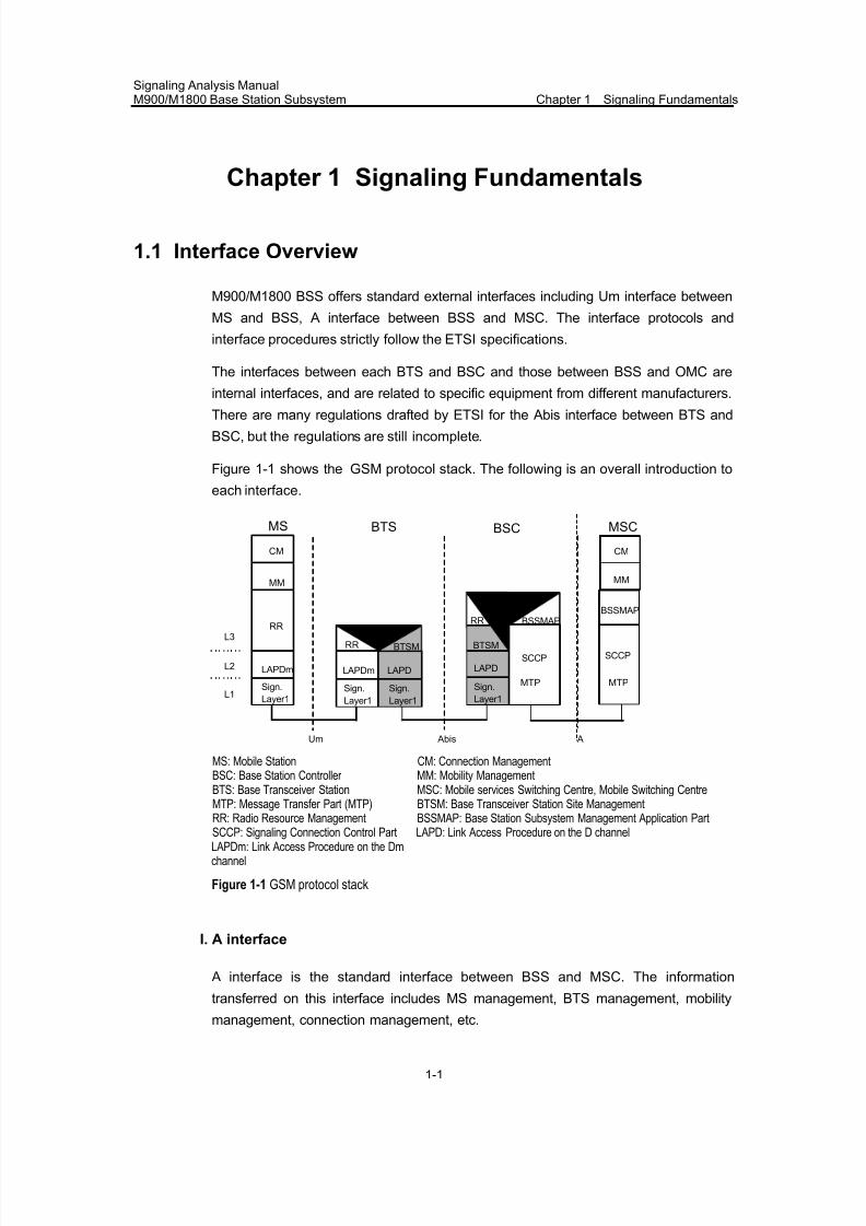
Figure 1-1 shows the GSM protocol stack. The following is an overall introduction to
each interface.
CM
MM
RR
LAPDm
Sign.
Layer1
L3
L2
L1
BTSM
MS
Um
SCCP
MTP
BTSM
RR BSSMAP
Abis
BTS
BSC
MSC
A
BSC
Sign.
Layer1
Sign.
Layer1
Sign.
Layer1
RR
LAPDLAPDm LAPD
CM
MM
BSSMAP
SCCP
MTP
MS: Mobile Station CM: Connection ManagementBSC: Base Station Controller MM: Mobility ManagementBTS: Base Transceiver Station MSC: Mobile services Switching Centre, Mobile Switching CentreMTP: Message Transfer Part (MTP) BTSM: Base Transceiver Station Site Management
RR: Radio Resource Management BSSMAP: Base Station Subsystem Management Application PartSCCP: Signaling Connection Control Part LAPD: Link Access Procedure on the D channelLAPDm: Link Access Procedure on the Dmchannel
Figure 1-1 GSM protocol stack
I. A interface
A interface is the standard interface between BSS and MSC. The information
transferred on this interface includes MS management, BTS management, mobility
management, connection management, etc.
7/30/2019 Signaling Analysis Manual
http://slidepdf.com/reader/full/signaling-analysis-manual 17/290
Signaling Analysis ManualM900/M1800 Base Station Subsystem Chapter 1 Signaling Fundamentals
1-2
II. Abis interface
Abis interface defines the standard of communication between BSC and BTS in BSS,
and is used in remote interconnection mode. This interface supports all MS-oriented
services, and supports the control of BTS radio equipment and the allocation of radio
frequencies.
III. Um interface
Um interface is defined as the communication interface between MS and BTS, and is
used for the interworking between MS and the fixed part of the GSM system. The
physical link is a radio link. The information transferred on this interface includes the
information of radio resource management, mobility management, connection
management, etc.
1.2 A-Interface
1.2.1 Overview
A interface is the interface between BSC and MSC. It is a standard interface in GSM
specifications, as it may involve the interworking between the equipment from
different manufactures. In the GSM system, SS7 is adopted on A interface.
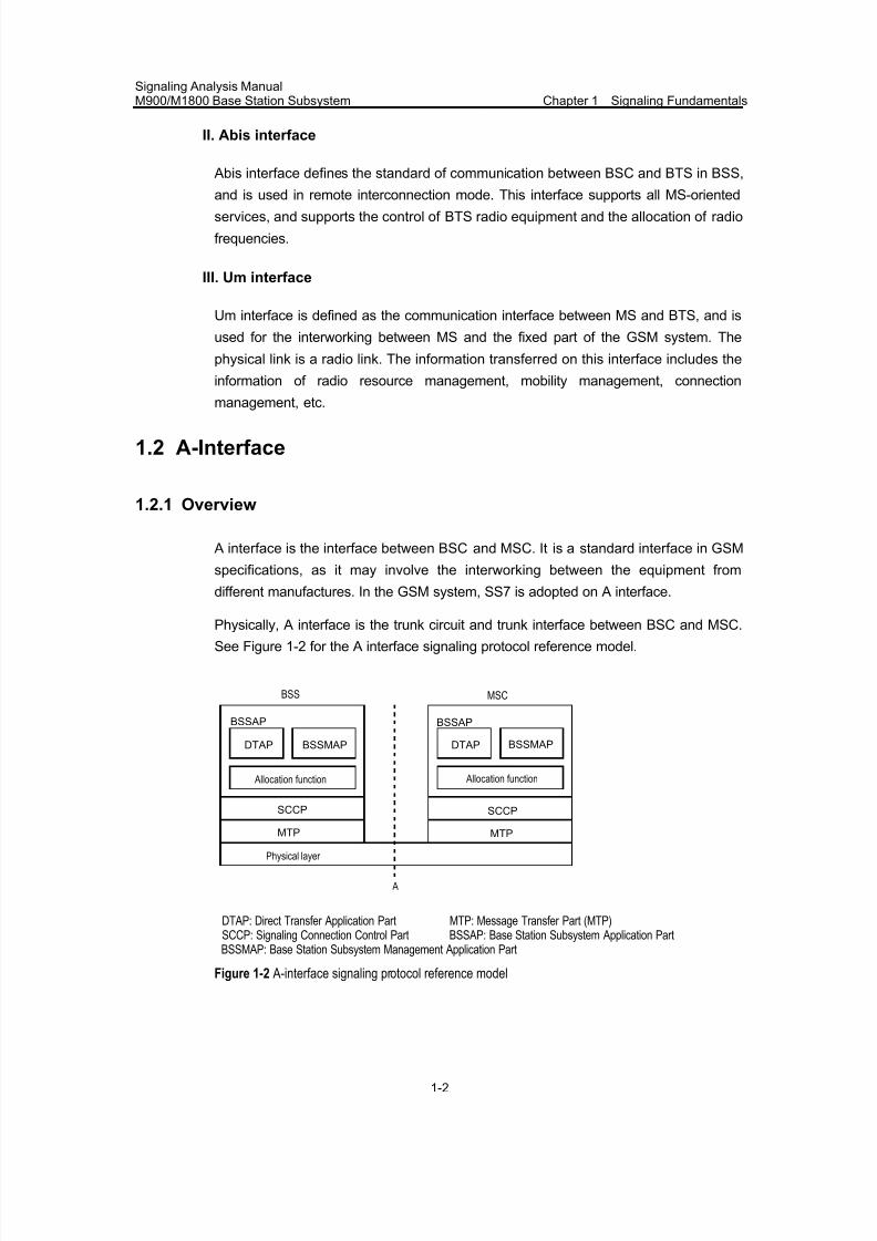
Physically, A interface is the trunk circuit and trunk interface between BSC and MSC.
See Figure 1-2 for the A interface signaling protocol reference model.
A
Physical layer
MTP
SCCP
BSSAP
DTAP BSSMAP
Allocation function
MTP
SCCP
BSSAP
DTAP BSSMAP
Allocation function
BSS MSC
DTAP: Direct Transfer Application Part MTP: Message Transfer Part (MTP)SCCP: Signaling Connection Control Part BSSAP: Base Station Subsystem Application PartBSSMAP: Base Station Subsystem Management Application Part
Figure 1-2 A-interface signaling protocol reference model
7/30/2019 Signaling Analysis Manual
http://slidepdf.com/reader/full/signaling-analysis-manual 18/290
Signaling Analysis ManualM900/M1800 Base Station Subsystem Chapter 1 Signaling Fundamentals
1-3
1.2.2 Protocols on the A-Interface
I. Physical layer
The physical layer of the A-interface is 120-ohm symmetrical twisted pair or 75-ohm
coaxial cable whose rate is 2 Mbit/s. The physical layer of A-interface has the
following features:
z The 2 Mbit/s transfer rate complies with G.703.
z Frame structure, synchronization and timing comply with G.705.
z Fault management complies with G.732.
z CRC4 complies with G.704.
II. Message Transfer Part (MTP)
The main function of MTP is to ensure reliable signaling message transfer in the
signaling network. In case of system and signaling network faults, it takes measures
to avoid or reduce the loss of messages, repeated messages and out-of-sequence
packets.
MTP protocols are defined in ITU-T Q.701~710 Recommendations.
MTP comprises three functional levels: signaling data link function, signaling link
function and signaling network function.
1) Signaling data link function
Signaling data link (layer 1) is the channel used for signaling transmission. It
comprises two data channels of the same data rate but two opposite working
directions. The data rate is 64kbit/s. Generally, the signaling data link occupies
timeslot 16 of a trunk cable. The specific timeslot is to be determined by negotiation
between BSC and MSC. By data configuration, the timeslot can be used to establish
a semi-permanent connection.
The signaling data link is the information bearer of SS7. One of its important features
is that the signaling link is transparent, i.e. the data transferred on it cannot be
changed. Therefore, equipment such as echo canceller, digital attenuator, A/u rateconverter, cannot be connected to this link.
2) Signaling link function
Signaling link function (layer 2) regulates the functions and procedures to send the
signaling to the data link, and together with layer 1, it implements reliable signaling
message transfer between two directly-connected signaling points. Due to
long-distance transmission, a certain rate of bit errors may be caused on the data link
between two adjacent signaling points. However, no error is allowed in CCS7
signaling message codes. The purpose of layer 2 is to guarantee error-free
transmission of message codes in the case that there exist bit errors on layer 1.
7/30/2019 Signaling Analysis Manual
http://slidepdf.com/reader/full/signaling-analysis-manual 19/290
Signaling Analysis ManualM900/M1800 Base Station Subsystem Chapter 1 Signaling Fundamentals
1-4
Functions of layer 2 include: signaling unit delimitation, signaling unit alignment, error
detection, error correction, initial alignment, processor fault, level-2 flow control, and
signaling link error rate monitoring.
3) Signaling network function
By controlling the route and performance of the signaling network, signaling network
function (level 3) guarantees that signaling information can be reliably transferred to
the user part, whether the signaling network is in normal state or not.. Signaling
network functions include signaling message processing and signaling network
management.
a) Signaling message processing
Signaling message processing function sends signaling messages to the
corresponding signaling links or user parts. The user part in BSS only contains SCCP.
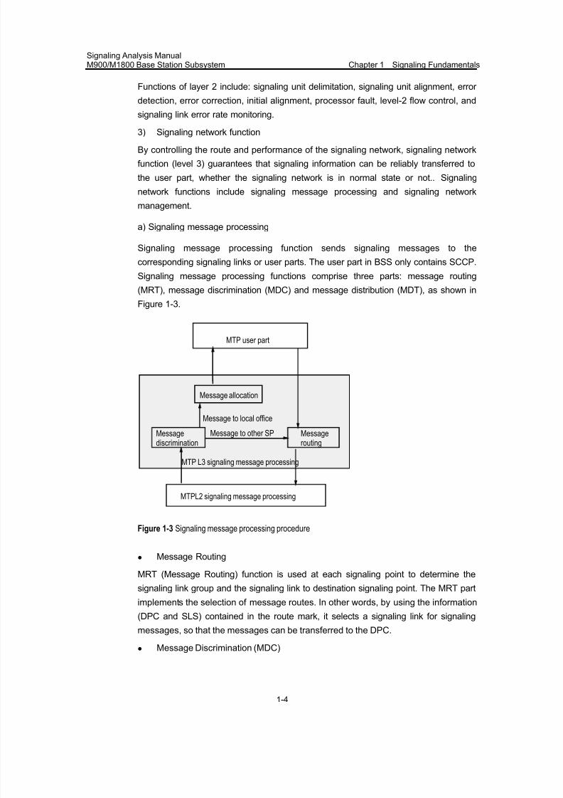
Signaling message processing functions comprise three parts: message routing
(MRT), message discrimination (MDC) and message distribution (MDT), as shown in
Figure 1-3.
Message allocation
Message to local office
Message to other SP
MTP user part
MTP L3 signaling message processing
MTPL2 signaling message processing
Messagerouting
Messagediscrimination
Figure 1-3 Signaling message processing procedure
z Message Routing
MRT (Message Routing) function is used at each signaling point to determine the
signaling link group and the signaling link to destination signaling point. The MRT part
implements the selection of message routes. In other words, by using the information
(DPC and SLS) contained in the route mark, it selects a signaling link for signaling
messages, so that the messages can be transferred to the DPC.
z Message Discrimination (MDC)
7/30/2019 Signaling Analysis Manual
http://slidepdf.com/reader/full/signaling-analysis-manual 20/290
Signaling Analysis ManualM900/M1800 Base Station Subsystem Chapter 1 Signaling Fundamentals
1-5
Message Discrimination (MDC) part is designed to receive the messages from Layer
2 to ascertain whether the destination of the messages is the local signaling point. If
the destination is the local signaling point, the MDC part will send the messages to
the Message Distribution (MDT) part. If the destination is not the local signaling point,the MDC part will send the messages to the Message Routing (MRT) part.
z Message Distribution (MDT)
Message Distribution (MDT) part is designed to allocate the messages from the MDC
part to the user part and the signaling network management and test & maintenance
part accordingly.
b) Signaling network management
Signaling network management is to re-construct the signaling network and to keep
and recover the normal transfer ability of the signaling unit when the signalingnetwork fails. Signaling network management includes three parts: signaling traffic
management, signaling link management and signaling route management.
z Signaling Traffic Management (STM)
Signaling Traffic Management (STM) is to transfer the signaling data from one
link/route to another or multiple available links/routes when the signaling network fails.
It is also used to temporarily reduce signaling traffic in case of congestion at the
signaling point.
z Signaling link management
Signaling link management (SLM) is to recover or enable the signaling link in the
signaling network or to disconnect the signaling link. It ensures the provision of
certain pre-determined link groups. The connection between the signaling data link
and the signaling terminal is normally established by the man-machine commands.
Operations in the signaling system can not automatically change the above
connection relationship.
z Signaling route management
Signaling route management (SRM) is used to ensure the reliable exchange of
signaling route availability information between signaling points so as to block or
unblock signaling routes when necessary. It mainly comprises such procedures as
transfer prohibited, transfer allowed, controlled transfer and restricted transfer,
signaling route group test, and signaling route group congestion test.
III. Signaling Connection & Control Part (SCCP)
The purpose of SCCP is to provide complete network layer functions with the help of
MTP. Network layer provides connectionless services and connection-oriented
services.
7/30/2019 Signaling Analysis Manual
http://slidepdf.com/reader/full/signaling-analysis-manual 21/290
Signaling Analysis ManualM900/M1800 Base Station Subsystem Chapter 1 Signaling Fundamentals
1-6
The network layer services provided by SCCP can be classified into connectionless
services and connection-oriented services. The connectionless service means that
MS does not establish a signaling connection in advance, and uses the routing
functions of SCCP and MTP to directly transfer data information in the signalingnetwork. It is applicable to the transfer of a small quantity of data. The
connection-oriented service means that a signaling connection is established in
advance, and data are directly transferred on the signaling link, instead of using the
route selection function of SCCP. It is applicable to the transfer of large quantities of
data, and effectively shortens the transmission delay of batch data.
SCCP has routing and network management functions. The routing function of SCCP
is to perform addressing as per the address information such as DPC, SSN, GT, etc.
DPC refers to the destination signaling point code adopted by MTP, and SSN refers to
the subsystem No., which is used to identify the different users (such as ISUP, MAP,TCAP and BSSAP) of SCCP in the same node, so as to compensate the insufficiency
of users of MTP and to enlarge the addressing scope. GT addressing mode is not
introduced as BSS does not adopt this addressing mode.
The network management function of SCCP is to implement management of
signaling point state and subsystem state, switchover of active/standby subsystem,
broadcasting of status messages and testing of subsystem state. SCMG (SCCP
management) is to maintain the network functions by reselecting a route or adjusting
the traffic volume when network fault or congestion occurs. MTP protocols are
defined in ITUT Q.711~716 Recommendations
IV. BSSAP
1) Protocol overview
The BSSAP protocol, which serves as A-interface specification, describes two kinds
of messages, BSSMAP and DTAP message. BSSMAP messages are used for traffic
flow control, and are to be processed by the internal functional module of the
corresponding A interface. For DTAP messages, A interface is merely equivalent to a
transport channel, On BSS side, DTAP messages are directly transferred to radio
channels. On MSC subsystem side, DTAP messages are transferred to thecorresponding functional processing unit.
BSSAP protocols are defined in ETSI GSM 08.08 and ETSI GSM 04.08
specifications.
2) Typical message contents
a) DTAP messages
The DTAP messages can be divided into Mobile Management (MM) messages and
Call Control (CC) messages.
7/30/2019 Signaling Analysis Manual
http://slidepdf.com/reader/full/signaling-analysis-manual 22/290
Signaling Analysis ManualM900/M1800 Base Station Subsystem Chapter 1 Signaling Fundamentals
1-7
The MM messages consist of messages related to authentication, CM service
request, identification request, IMSI detach, location update, MM state, TMSI
re-allocation, etc.
The call control messages consist of alerting, call proceeding, connection, setup,
modification, release, disconnection, notification, state query, DTMF startup
messages, etc.
b) BSSMAP messages
The BSSMAP messages can be divided into connectionless and connection-oriented
messages.
z The connectionless messages consist of Block/Unblock, Handover, Resource,
Reset, Paging messages, etc.
The Block/Unblock messages include Block & Block ACK messages and Unblock &
Unblock ACK messages. The Circuit Group Block/Unblock messages include Circuit
Group Block message, Circuit Group Block ACK message, Circuit Group Unblock and
Circuit Group Unblock messages.
Handover messages include Handover Candidate Enquire and Handover Candidate
Enquire Response.
The resources messages include Resources Request and Resource Indication
messages.
The Reset messages include Reset and Reset ACK messages.
z The connection-oriented messages include Assignment, Handover, Clear and
Cipher messages.
The Assignment messages include Assignment Request, Assignment Complete and
Assignment Error messages.
The Handover messages include Handover Request, Handover Request ACK,
Handover Command, Handover Complete and Handover Error messages.
The Clear messages include Clear Request and Clear Complete messages.
The Cipher messages include Cipher Mode Command and Cipher Mode Complete
messages.
c) BSSAP protocol functionality
The BSSAP protocol can deliver its own functions in connection-oriented mode and
connectionless mode of SCCP. When MS needs to exchange service-related
messages over radio resources with the network side while there is no MS-related
SCCP connection between MSC and BSS, a new connection will be established. A
new connection shall also be set up for external handover. There are two kinds of
connection setup:
7/30/2019 Signaling Analysis Manual
http://slidepdf.com/reader/full/signaling-analysis-manual 23/290
Signaling Analysis ManualM900/M1800 Base Station Subsystem Chapter 1 Signaling Fundamentals
1-8
z While MS sends the Access Request message on the RACH, BSS allocates a
dedicated radio resource (DCCH or TCH) to MS. After the L2 connection is set
up on the SDCCH (or FACCH) where resources are allocated, BSS starts the
connection setup.z When MSC decides to execute an external handover (the target BSS might be
the original BSS), it must reserve a new DCCH or TCH from the target BSS. In
this scenario, MSC starts the connection setup.
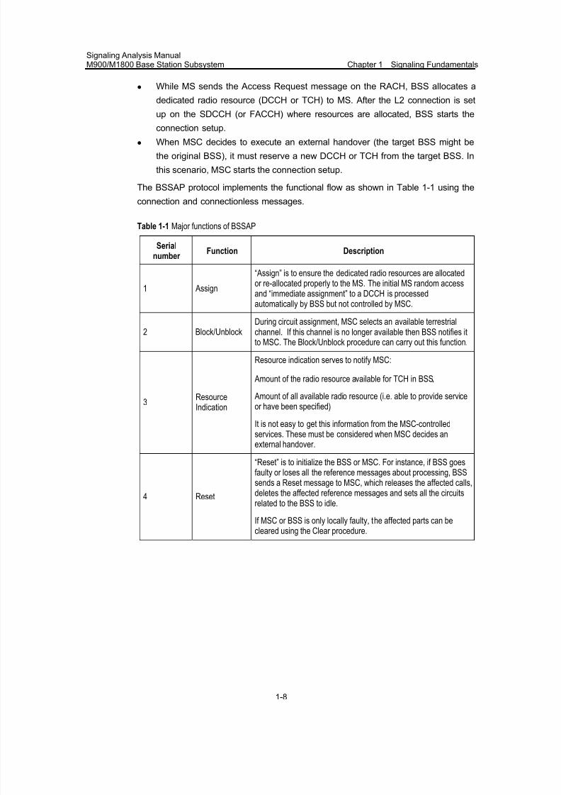
The BSSAP protocol implements the functional flow as shown in Table 1-1 using the
connection and connectionless messages.
Table 1-1 Major functions of BSSAP
Serialnumber
Function Description
1 Assign
“Assign” is to ensure the dedicated radio resources are allocatedor re-allocated properly to the MS. The initial MS random accessand “immediate assignment” to a DCCH is processedautomatically by BSS but not controlled by MSC.
2 Block/UnblockDuring circuit assignment, MSC selects an available terrestrialchannel. If this channel is no longer available then BSS notifies itto MSC. The Block/Unblock procedure can carry out this function.
3 ResourceIndication
Resource indication serves to notify MSC:
Amount of the radio resource available for TCH in BSS,
Amount of all available radio resource (i.e. able to provide serviceor have been specified)
It is not easy to get this information from the MSC-controlledservices. These must be considered when MSC decides anexternal handover.
4 Reset
“Reset” is to initialize the BSS or MSC. For instance, if BSS goesfaulty or loses all the reference messages about processing, BSSsends a Reset message to MSC, which releases the affected calls,deletes the affected reference messages and sets all the circuitsrelated to the BSS to idle.
If MSC or BSS is only locally faulty, the affected parts can be
cleared using the Clear procedure.
7/30/2019 Signaling Analysis Manual
http://slidepdf.com/reader/full/signaling-analysis-manual 24/290
Signaling Analysis ManualM900/M1800 Base Station Subsystem Chapter 1 Signaling Fundamentals
1-9
Serialnumber
Function Description
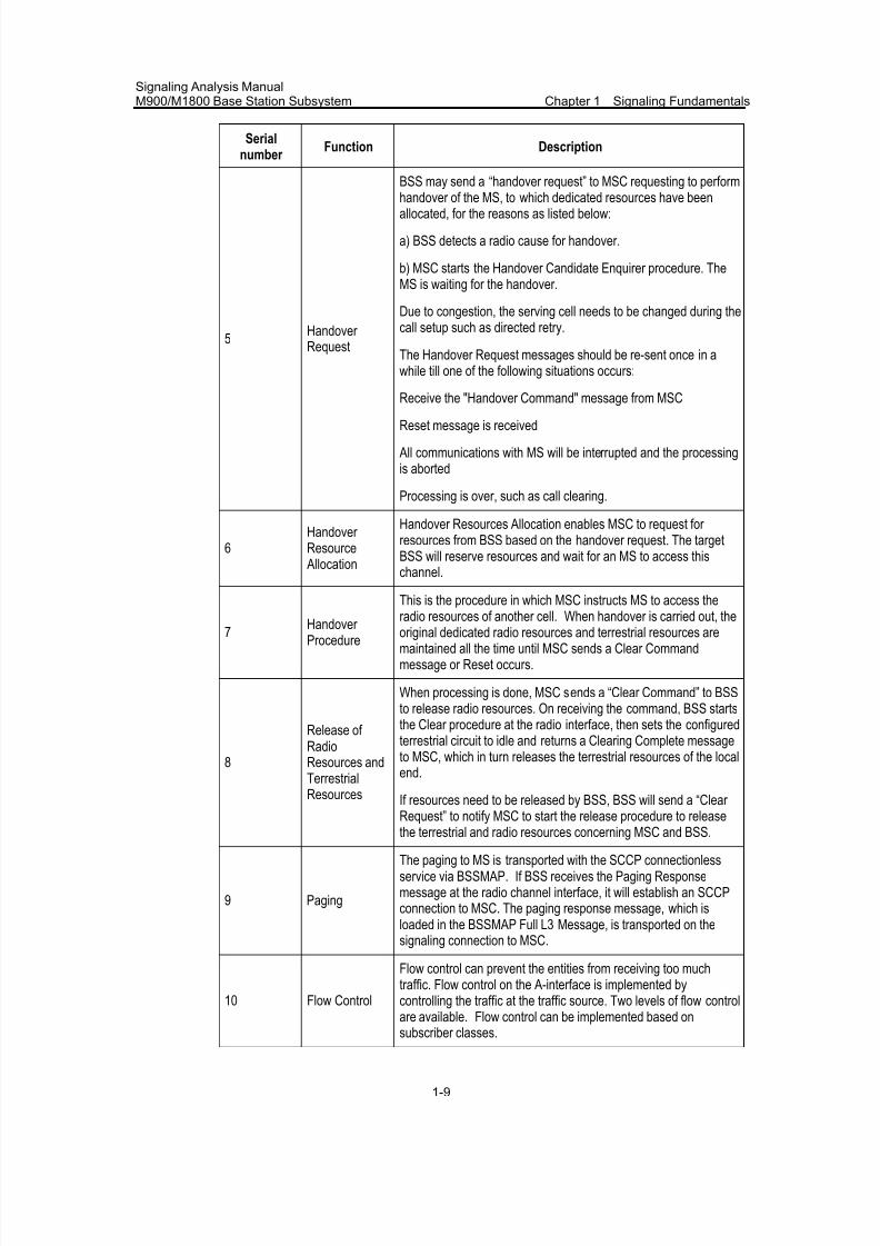
5Handover Request
BSS may send a “handover request” to MSC requesting to performhandover of the MS, to which dedicated resources have beenallocated, for the reasons as listed below:
a) BSS detects a radio cause for handover.
b) MSC starts the Handover Candidate Enquirer procedure. TheMS is waiting for the handover.
Due to congestion, the serving cell needs to be changed during thecall setup such as directed retry.
The Handover Request messages should be re-sent once in awhile till one of the following situations occurs:
Receive the "Handover Command" message from MSC
Reset message is received
All communications with MS will be interrupted and the processingis aborted
Processing is over, such as call clearing.
6Handover Resource Allocation
Handover Resources Allocation enables MSC to request for resources from BSS based on the handover request. The targetBSS will reserve resources and wait for an MS to access thischannel.
7 Handover Procedure
This is the procedure in which MSC instructs MS to access theradio resources of another cell. When handover is carried out, theoriginal dedicated radio resources and terrestrial resources aremaintained all the time until MSC sends a Clear Commandmessage or Reset occurs.
8
Release of RadioResources andTerrestrialResources
When processing is done, MSC sends a “Clear Command” to BSSto release radio resources. On receiving the command, BSS startsthe Clear procedure at the radio interface, then sets the configuredterrestrial circuit to idle and returns a Clearing Complete messageto MSC, which in turn releases the terrestrial resources of the localend.
If resources need to be released by BSS, BSS will send a “Clear Request” to notify MSC to start the release procedure to release
the terrestrial and radio resources concerning MSC and BSS.
9 Paging
The paging to MS is transported with the SCCP connectionlessservice via BSSMAP. If BSS receives the Paging Responsemessage at the radio channel interface, it will establish an SCCPconnection to MSC. The paging response message, which isloaded in the BSSMAP Full L3 Message, is transported on thesignaling connection to MSC.
10 Flow Control
Flow control can prevent the entities from receiving too muchtraffic. Flow control on the A-interface is implemented bycontrolling the traffic at the traffic source. Two levels of flow controlare available. Flow control can be implemented based on
subscriber classes.
7/30/2019 Signaling Analysis Manual
http://slidepdf.com/reader/full/signaling-analysis-manual 25/290
Signaling Analysis ManualM900/M1800 Base Station Subsystem Chapter 1 Signaling Fundamentals
1-10
Serialnumber
Function Description
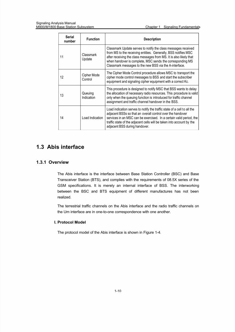
11 ClassmarkUpdate
Classmark Update serves to notify the class messages receivedfrom MS to the receiving entities. Generally, BSS notifies MSCafter receiving the class messages from MS. It is also likely thatwhen handover is complete, MSC sends the corresponding MSClassmark messages to the new BSS via the A-interface.
12Cipher ModeControl
The Cipher Mode Control procedure allows MSC to transport thecipher mode control messages to BSS and start the subscriber equipment and signaling cipher equipment with a correct Kc.
13QueuingIndication
This procedure is designed to notify MSC that BSS wants to delaythe allocation of necessary radio resources. This procedure is validonly when the queuing function is introduced for traffic channelassignment and traffic channel handover in the BSS.
14 Load Indication
Load indication serves to notify the traffic state of a cell to all theadjacent BSSs so that an overall control over the handover services in an MSC can be exercised. In a certain valid period, thetraffic state of the adjacent cells will be taken into account by theadjacent BSS during handover.
1.3 Abis interface
1.3.1 Overview
The Abis interface is the interface between Base Station Controller (BSC) and Base
Transceiver Station (BTS), and complies with the requirements of 08.5X series of the
GSM specifications. It is merely an internal interface of BSS. The interworking
between the BSC and BTS equipment of different manufactures has not been
realized.
The terrestrial traffic channels on the Abis interface and the radio traffic channels on
the Um interface are in one-to-one correspondence with one another.
I. Protocol Model
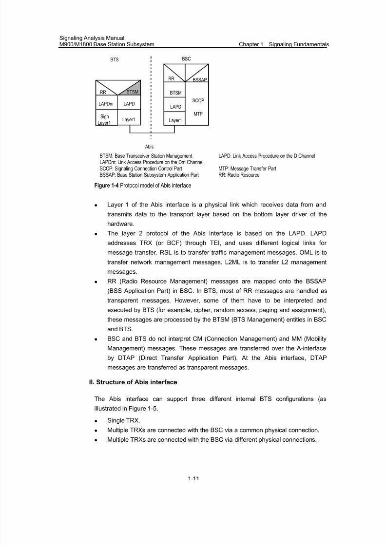
The protocol model of the Abis interface is shown in Figure 1-4.
7/30/2019 Signaling Analysis Manual
http://slidepdf.com/reader/full/signaling-analysis-manual 26/290
Signaling Analysis ManualM900/M1800 Base Station Subsystem Chapter 1 Signaling Fundamentals
1-11
LAPDm
Sign
Layer1
LAPD
Layer1
LAPD
Layer1
SCCP
MTP
BTSM
RR BSSAP
Abis
BTS BSC
RR BTSM
BTSM: Base Transceiver Station Management LAPD: Link Access Procedure on the D ChannelLAPDm: Link Access Procedure on the Dm ChannelSCCP: Signaling Connection Control Part MTP: Message Transfer PartBSSAP: Base Station Subsystem Application Part RR: Radio Resource
Figure 1-4 Protocol model of Abis interface
z Layer 1 of the Abis interface is a physical link which receives data from and
transmits data to the transport layer based on the bottom layer driver of the
hardware.
z The layer 2 protocol of the Abis interface is based on the LAPD. LAPD
addresses TRX (or BCF) through TEI, and uses different logical links for
message transfer. RSL is to transfer traffic management messages. OML is to
transfer network management messages. L2ML is to transfer L2 management
messages.z RR (Radio Resource Management) messages are mapped onto the BSSAP
(BSS Application Part) in BSC. In BTS, most of RR messages are handled as
transparent messages. However, some of them have to be interpreted and
executed by BTS (for example, cipher, random access, paging and assignment),
these messages are processed by the BTSM (BTS Management) entities in BSC
and BTS.
z BSC and BTS do not interpret CM (Connection Management) and MM (Mobility
Management) messages. These messages are transferred over the A-interface
by DTAP (Direct Transfer Application Part). At the Abis interface, DTAP
messages are transferred as transparent messages.
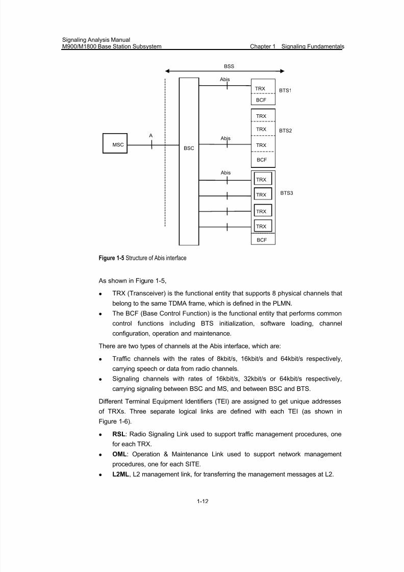
II. Structure of Abis interface
The Abis interface can support three different internal BTS configurations (as
illustrated in Figure 1-5.
z Single TRX.
z Multiple TRXs are connected with the BSC via a common physical connection.
z Multiple TRXs are connected with the BSC via different physical connections.
7/30/2019 Signaling Analysis Manual
http://slidepdf.com/reader/full/signaling-analysis-manual 27/290
Signaling Analysis ManualM900/M1800 Base Station Subsystem Chapter 1 Signaling Fundamentals
1-12
Abis
BTS3
BTS2
BTS1
A
Abis
MSCBSC
TRX
BCF
TRX
BCF
Abis
BSS
TRX
TRX
TRX
TRX
TRX
TRX
BCF
Figure 1-5 Structure of Abis interface
As shown in Figure 1-5,
z TRX (Transceiver) is the functional entity that supports 8 physical channels that
belong to the same TDMA frame, which is defined in the PLMN.
z The BCF (Base Control Function) is the functional entity that performs common
control functions including BTS initialization, software loading, channel
configuration, operation and maintenance.
There are two types of channels at the Abis interface, which are:
z Traffic channels with the rates of 8kbit/s, 16kbit/s and 64kbit/s respectively,
carrying speech or data from radio channels.
z
Signaling channels with rates of 16kbit/s, 32kbit/s or 64kbit/s respectively,carrying signaling between BSC and MS, and between BSC and BTS.
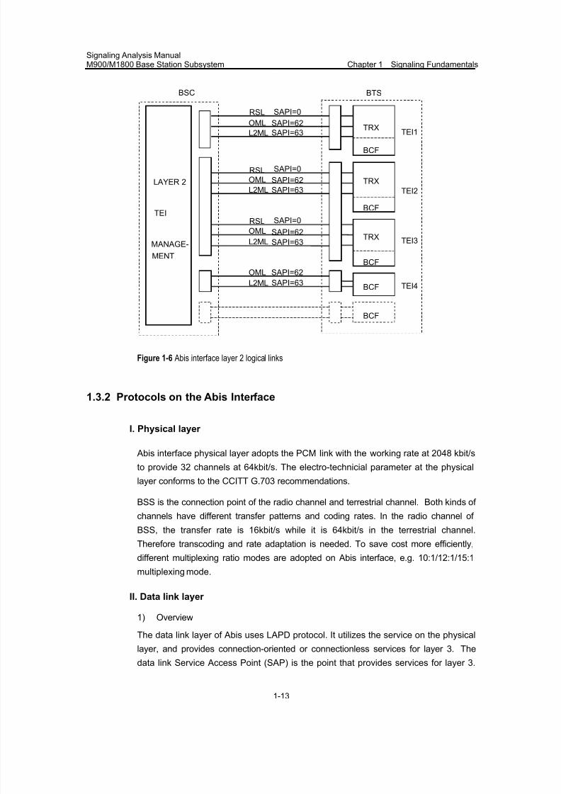
Different Terminal Equipment Identifiers (TEI) are assigned to get unique addresses
of TRXs. Three separate logical links are defined with each TEI (as shown in
Figure 1-6).
z RSL: Radio Signaling Link used to support traffic management procedures, one
for each TRX.
z OML: Operation & Maintenance Link used to support network management
procedures, one for each SITE.
z
L2ML, L2 management link, for transferring the management messages at L2.
7/30/2019 Signaling Analysis Manual
http://slidepdf.com/reader/full/signaling-analysis-manual 28/290
Signaling Analysis ManualM900/M1800 Base Station Subsystem Chapter 1 Signaling Fundamentals
1-13
TEI1L2ML SAPI=63
RSL SAPI=0
OML SAPI=62
LAYER 2
TEI
MANAGE-
MENT
TRX
TRX
TRX
BCF
L2ML SAPI=63
RSL SAPI=0
OML SAPI=62
L2ML SAPI=63
RSL SAPI=0
OML SAPI=62
BCF
BCF
BCF
BCF
L2ML SAPI=63
OML SAPI=62
BSC BTS
TEI2
TEI3
TEI4
Figure 1-6 Abis interface layer 2 logical links
1.3.2 Protocols on the Abis Interface
I. Physical layer
Abis interface physical layer adopts the PCM link with the working rate at 2048 kbit/s
to provide 32 channels at 64kbit/s. The electro-technicial parameter at the physical
layer conforms to the CCITT G.703 recommendations.
BSS is the connection point of the radio channel and terrestrial channel. Both kinds of
channels have different transfer patterns and coding rates. In the radio channel of
BSS, the transfer rate is 16kbit/s while it is 64kbit/s in the terrestrial channel.Therefore transcoding and rate adaptation is needed. To save cost more efficiently,
different multiplexing ratio modes are adopted on Abis interface, e.g. 10:1/12:1/15:1
multiplexing mode.
II. Data link layer
1) Overview
The data link layer of Abis uses LAPD protocol. It utilizes the service on the physical
layer, and provides connection-oriented or connectionless services for layer 3. The
data link Service Access Point (SAP) is the point that provides services for layer 3.
7/30/2019 Signaling Analysis Manual
http://slidepdf.com/reader/full/signaling-analysis-manual 29/290
Signaling Analysis ManualM900/M1800 Base Station Subsystem Chapter 1 Signaling Fundamentals
1-14
SAP is identified by Service Access Point Identifier (SAPI). A data link connection
endpoint is identified by a data link connection endpoint identifier as seen from layer 3
and by a data link connection identifier (DLCI) as seen from the data link layer.
For information exchange between two or more layer 3 entities, an association must
be established between the layer 3 entities in the data link layer using a data link
layer protocol.
The communication between data link layer entities is governed by a peer-to-peer
protocol specific to the layer. Messages at the data link layer are transferred between
entities at layer 2 through physical layer. Inter-layer service request is implemented
with service primitive.
2) Function
The purpose of LAPD is to realize reliable end-to-end information transfer betweenlayer 3 entities through the user-network interface by using the D-channel. To be
specific, LAPD supports:
z Multiple terminal equipment between subscriber and interface,
z Multiple L3 entities.
Functions of LAPD includes:
z Establishes one or several data links on the D channel.
z Delimits, locates and transmits transparently frames so that a string of bits
transmitted on the D channel in the form of frames can be identified.
z Implements sequence control to keep the order of the frames that pass the datalink connections.
z Checks the transmission errors, format errors and operation errors in the data
link connections.
z Makes recovery based on the detected transmission errors, format errors and
operation errors.
z Notifies the management layer entities of the unrecoverable errors.
z Flow control.
Data link layer provides the means for information transfer between multiple
combinations of data link connection points. The information may be transferred
through point-to-point data link connections or via broadcast data link connections.
III. Traffic management of Layer 3
The traffic management part of the Abis interface layer 3 is mainly described in GSM
08.58 specifications. The procedures defined in this specifications has two major
functions:
z Realizing the interworking of the MS and BSS/NSS on the Um interface.
z Implementing part of the radio resource management functions under the control
of BSC.
7/30/2019 Signaling Analysis Manual
http://slidepdf.com/reader/full/signaling-analysis-manual 30/290
Signaling Analysis ManualM900/M1800 Base Station Subsystem Chapter 1 Signaling Fundamentals
1-15
The traffic management message is divided into the transparent and non-transparent
messages,
z The transparent message refers to the messages forwarded without
interpretation or being processed by the BTS. z The non-transparent message refers to the messages processed and structured
by the BTS.
The traffic management messages can also be divided into four groups in terms of
functions, which are:
z Radio link layer management message, used for the management of the data
link layer on the radio channel.
z Dedicated channel management message used for the management of
dedicated channels (SDCCH and TCH).
z Common control channel management message used for the management of common control channels.
z TRX management message used for TRX management.
z
Transparency and group of the message is determined by the message discriminator
at the header of the message.
1) Radio link layer management procedures
Radio link layer management procedures include:
z Link establishment indication procedure: BTS uses this procedure to indicate to
BSC the success of setting up multi-frame link originated by the subscriber. BSC
establishes a link from MSC to SCCP through the indication.
z Link establishment request procedure: This procedure is used by BSC to request
the establishment of a link layer connection in multi-frame mode on the radio
channel.
z Link release indication procedure: This procedure is used by BTS to indicate to
BSC that a link layer connection on the radio channel has been released at the
initiative of an MS.
z Link release request procedure: This procedure is used by BSC to request the
release of a link layer connection on the radio channel. z Transmission of a transparent L3-message on the Um interface in acknowledged
mode: This procedure is used by BSC to request the sending of a transparent L3
message to MS on the Um interface in acknowledged mode.
z Reception of a transparent L3-message on the Um interface in acknowledged
mode: This procedure is used by BTS to indicate the reception of a transparent
L3 message on the Um interface in acknowledged mode.
z Transmission of a transparent L3-message on the Um interface in
unacknowledged mode: This procedure is used by BSC to request the sending
of a transparent L3 message to MS on the Um interface in unacknowledged
mode.
7/30/2019 Signaling Analysis Manual
http://slidepdf.com/reader/full/signaling-analysis-manual 31/290
Signaling Analysis ManualM900/M1800 Base Station Subsystem Chapter 1 Signaling Fundamentals
1-16
z Reception of a transparent L3-message on the Um interface in unacknowledged
mode: This procedure is used by BTS to indicate the reception of a transparent
L3 message in unacknowledged mode.
z
Link error indication procedure: Through this procedure BTS indicates BSCincase of any abnormality in the radio link layer.
2) Dedicated channel management procedures
The dedicated channel management principles includes:
z Channel activation procedure: This procedure is used to activate a channel at
BTS for an MS which later will be commanded to this channel by an Immediate
Assignment, an Assignment Command, an Additional Assignment or a Handover
Command message.
z Channel mode modification procedure: This procedure is used by BSC to
request a change of the channel mode of an active channel.
z Handover detection procedure: This procedure is used between the target BTS
and BSC to detect the accessing of the MS being handed over.
z Start of encryption procedure: This procedure is used to start encryption
according to the procedure defined in Technical Specification GSM 04.08.
z Measurement report procedure: It includes the necessary basic measurement
report procedure and measurement report preprocessing procedure. BTS reports
all parameters related to handover decision to the BSC through this procedure.
z Deactivate SACCH procedure: This procedure is used by BSC to deactivate the
SACCH at BTS according to the Channel Release procedure defined in
Technical Specification GSM 04.08.
z Radio channel release procedure: This procedure is used by BSC to release a
radio channel that is no longer needed.
z MS power control procedure: This procedure is used by BSS to set the MS
power level or the parameters required by TRX. MS power control decision must
be implemented in BSC, and as an optional procedure in BTS.
z BTS Transmission power control procedure: This procedure used between BSC
and BTS to set the TRX transmission power level or the parameters required by
TRX. The BTS transmission power control decision should be implemented in
BSC, or in BTS.
z Connection failure procedure: This procedure is used by BTS to indicate to BSC
that an active connection has been broken.
z Physical context request procedure: This is an optional procedure which allows
the BSC to obtain information on the "physical context" of a radio channel just
prior to a channel change.
z SACCH information modification procedure: BSC uses this procedure to instruct
BTS to change the information (system information) filled in a specific SACCH
channel.
3) Common channel management procedures
Common channel management regulations include:
7/30/2019 Signaling Analysis Manual
http://slidepdf.com/reader/full/signaling-analysis-manual 32/290
Signaling Analysis ManualM900/M1800 Base Station Subsystem Chapter 1 Signaling Fundamentals
1-17
z Channel request by MS procedure: The procedure is initiated by TRX upon
detection of a random access from an MS (Channel Request message from
MS).
z
Paging principle procedure: It is used to page an MS on the specified pagingsub-channel. The paging of an MS is initiated by BSC sending a Paging
Command message to BTS. BSC determines the paging group to be used
according to the IMSI of the called MS. The value of this paging group together
with the identity of the mobile station is sent to BTS.
z Immediate assignment procedure: When a mobile station accesses BTS, BSC
uses this procedure to assign a dedicated channel for the mobile station
immediately.
z Delete indication procedure: This procedure is used by BTS to indicate that due
to overload on the AGCH, an Immediate Assign Command has been deleted.
z CCCH load indication procedure: This procedure is used by BTS to inform BSC
the load on a designate CCCH. Indication period is also set by OM.
z Broadcast information modification procedure: This procedure is used by BSC to
indicate to BTS the new information to be broadcast on BCCH.
z Short message cell broadcast procedure: Short Message Service Cell Broadcast
messages are sent to BTS as SMS Broadcast Request messages.
4) TRX management procedures
This type of procedure is used for TRX management. There are:
z SACCH filling information modify procedure: This procedure is used by BSC to
indicate to BTS the new information to be used as filling information on SACCHs.
z Radio resources indication procedure: This procedure is used to inform BSC on
the interference levels on idle channels of a TRX.
z Flow control procedure: This procedure is defined to give some degree of flow
control. It can be used for TRX processor overload, downlink CCCH overload
and AGCH overload.
z Error reporting procedure: This procedure is used by BTS to report detected
downlink message errors, which cannot be reported by any other procedure.
IV. Operation and maintenance part of Layer 3
1) Operation and maintenance information model
z Managed objects
There are four types of management objects: site, cell, carrier and channel. The basic
structure is illustrated in Figure 1-7.
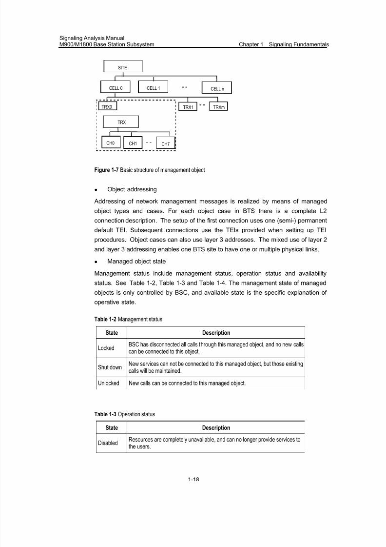
7/30/2019 Signaling Analysis Manual
http://slidepdf.com/reader/full/signaling-analysis-manual 33/290
Signaling Analysis ManualM900/M1800 Base Station Subsystem Chapter 1 Signaling Fundamentals
1-18
SITE
CELL 0 CELL 1CELL n
TRX0 TRX1 TRXm
TRX
CH0 CH1 CH7
Figure 1-7 Basic structure of management object
z Object addressing
Addressing of network management messages is realized by means of managed
object types and cases. For each object case in BTS there is a complete L2
connection description. The setup of the first connection uses one (semi-) permanent
default TEI. Subsequent connections use the TEIs provided when setting up TEI
procedures. Object cases can also use layer 3 addresses. The mixed use of layer 2
and layer 3 addressing enables one BTS site to have one or multiple physical links.
z Managed object state
Management status include management status, operation status and availabilitystatus. See Table 1-2, Table 1-3 and Table 1-4. The management state of managed
objects is only controlled by BSC, and available state is the specific explanation of
operative state.
Table 1-2 Management status
State Description
LockedBSC has disconnected all calls through this managed object, and no new callscan be connected to this object.
Shut down New services can not be connected to this managed object, but those existingcalls will be maintained.
Unlocked New calls can be connected to this managed object.
Table 1-3 Operation status
State Description
DisabledResources are completely unavailable, and can no longer provide services tothe users.
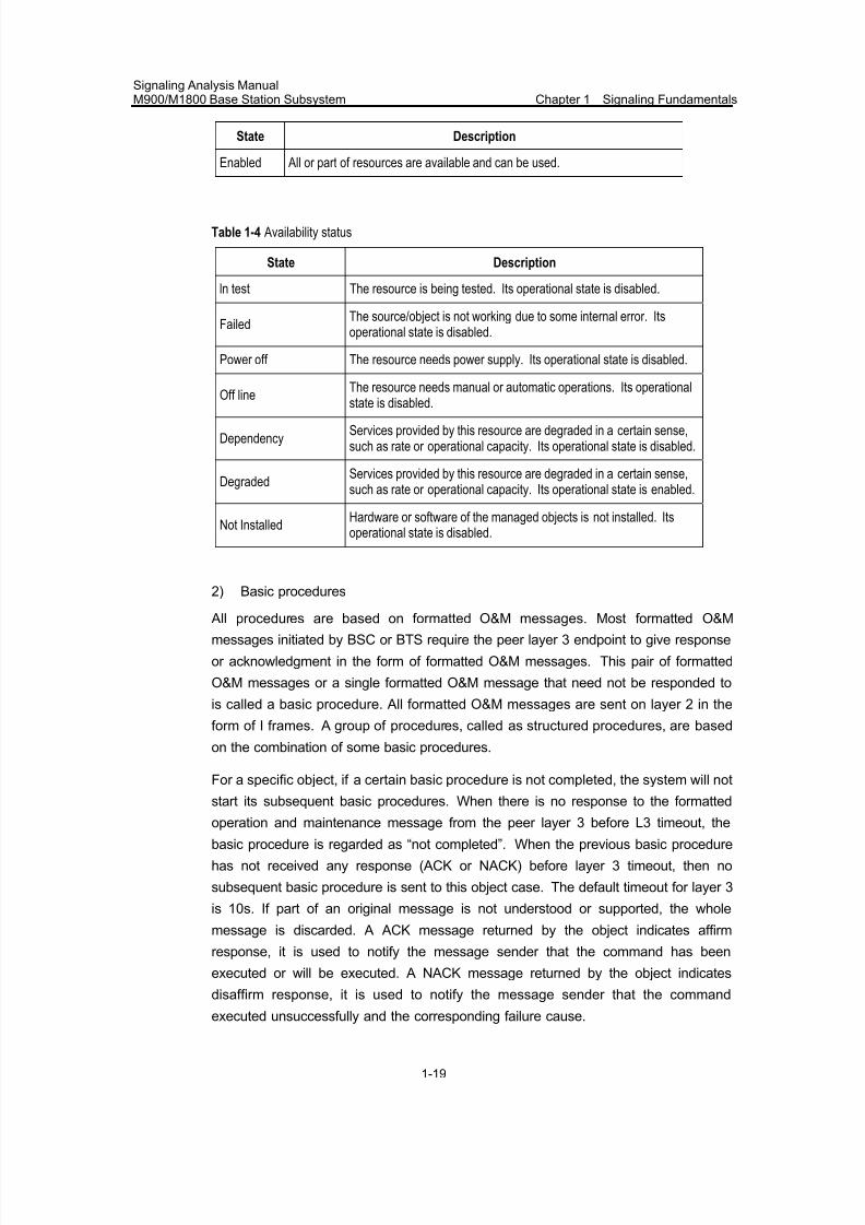
7/30/2019 Signaling Analysis Manual
http://slidepdf.com/reader/full/signaling-analysis-manual 34/290
Signaling Analysis ManualM900/M1800 Base Station Subsystem Chapter 1 Signaling Fundamentals
1-19
State Description
Enabled All or part of resources are available and can be used.
Table 1-4 Availability status
State Description
ln test The resource is being tested. Its operational state is disabled.
FailedThe source/object is not working due to some internal error. Itsoperational state is disabled.
Power off The resource needs power supply. Its operational state is disabled.
Off lineThe resource needs manual or automatic operations. Its operational
state is disabled.
DependencyServices provided by this resource are degraded in a certain sense,such as rate or operational capacity. Its operational state is disabled.
DegradedServices provided by this resource are degraded in a certain sense,such as rate or operational capacity. Its operational state is enabled.
Not InstalledHardware or software of the managed objects is not installed. Itsoperational state is disabled.
2) Basic procedures
All procedures are based on formatted O&M messages. Most formatted O&M
messages initiated by BSC or BTS require the peer layer 3 endpoint to give response
or acknowledgment in the form of formatted O&M messages. This pair of formatted
O&M messages or a single formatted O&M message that need not be responded to
is called a basic procedure. All formatted O&M messages are sent on layer 2 in the
form of I frames. A group of procedures, called as structured procedures, are based
on the combination of some basic procedures.
For a specific object, if a certain basic procedure is not completed, the system will not
start its subsequent basic procedures. When there is no response to the formatted
operation and maintenance message from the peer layer 3 before L3 timeout, the
basic procedure is regarded as “not completed”. When the previous basic procedure
has not received any response (ACK or NACK) before layer 3 timeout, then no
subsequent basic procedure is sent to this object case. The default timeout for layer 3
is 10s. If part of an original message is not understood or supported, the whole
message is discarded. A ACK message returned by the object indicates affirm
response, it is used to notify the message sender that the command has been
executed or will be executed. A NACK message returned by the object indicates
disaffirm response, it is used to notify the message sender that the command
executed unsuccessfully and the corresponding failure cause.
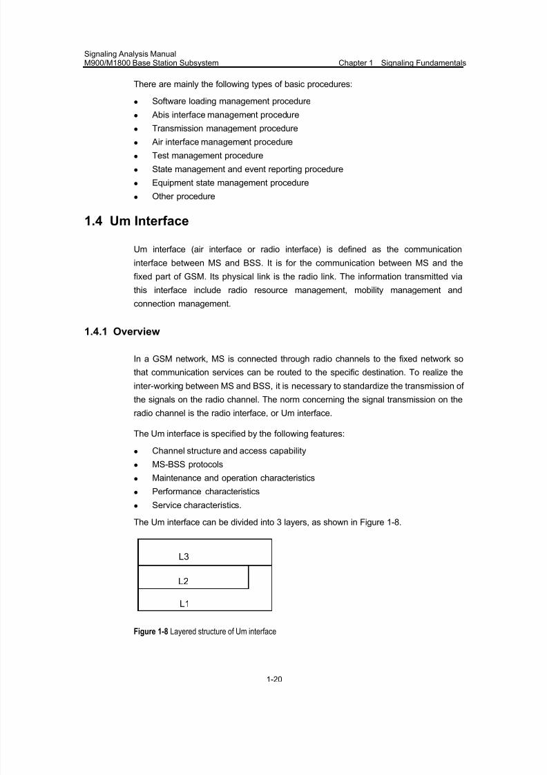
7/30/2019 Signaling Analysis Manual
http://slidepdf.com/reader/full/signaling-analysis-manual 35/290
Signaling Analysis ManualM900/M1800 Base Station Subsystem Chapter 1 Signaling Fundamentals
1-20
There are mainly the following types of basic procedures:
z Software loading management procedure
z Abis interface management procedure
z Transmission management procedurez Air interface management procedure
z Test management procedure
z State management and event reporting procedure
z Equipment state management procedure
z Other procedure
1.4 Um Interface
Um interface (air interface or radio interface) is defined as the communication
interface between MS and BSS. It is for the communication between MS and the
fixed part of GSM. Its physical link is the radio link. The information transmitted via
this interface include radio resource management, mobility management and
connection management.
1.4.1 Overview
In a GSM network, MS is connected through radio channels to the fixed network so
that communication services can be routed to the specific destination. To realize the
inter-working between MS and BSS, it is necessary to standardize the transmission of the signals on the radio channel. The norm concerning the signal transmission on the
radio channel is the radio interface, or Um interface.
The Um interface is specified by the following features:
z Channel structure and access capability
z MS-BSS protocols
z Maintenance and operation characteristics
z Performance characteristics
z Service characteristics.
The Um interface can be divided into 3 layers, as shown in Figure 1-8.
L3
L2
L1
Figure 1-8 Layered structure of Um interface
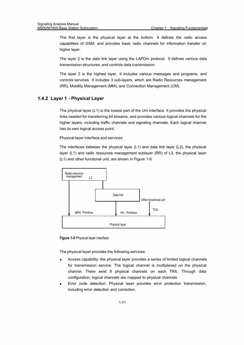
7/30/2019 Signaling Analysis Manual
http://slidepdf.com/reader/full/signaling-analysis-manual 36/290
Signaling Analysis ManualM900/M1800 Base Station Subsystem Chapter 1 Signaling Fundamentals
1-21
The first layer is the physical layer at the bottom. It defines the radio access
capabilities of GSM, and provides basic radio channels for information transfer on
higher layer.
The layer 2 is the data link layer using the LAPDm protocol. It defines various data
transmission structures, and controls data transmission.
The layer 3 is the highest layer. It includes various messages and programs, and
controls services. It includes 3 sub-layers, which are Radio Resources management
(RR), Mobility Management (MM), and Connection Management (CM).
1.4.2 Layer 1 - Physical Layer
The physical layer (L1) is the lowest part of the Um interface. It provides the physical
links needed for transferring bit streams, and provides various logical channels for the
higher layers, including traffic channels and signaling channels. Each logical channel
has its own logical access point.
Physical layer interface and services:
The interfaces between the physical layer (L1) and data link layer (L2), the physical
layer (L1) and radio resources management sublayer (RR) of L3, the physical layer
(L1) and other functional unit, are shown in Figure 1-9.
Radio resourcemanagement L3
Data link
MPH Primitive PH Primitive
Physical layer
TCH
Other functional unit
Figure 1-9 Physical layer interface
The physical layer provides the following services:
z Access capability: the physical layer provides a series of limited logical channels
for transmission service. The logical channel is multiplexed on the physical
channel. There exist 8 physical channels on each TRX. Through data
configuration, logical channels are mapped to physical channels
z Error code detection: Physical layer provides error protection transmission,
including error detection and correction.
7/30/2019 Signaling Analysis Manual
http://slidepdf.com/reader/full/signaling-analysis-manual 37/290
Signaling Analysis ManualM900/M1800 Base Station Subsystem Chapter 1 Signaling Fundamentals
1-22
z Ciphering: Use the selected encrypt algorithm to transmit bit sequence
encrypted.
1.4.3 Layer 2 - Data Link Layer
The purpose of the data link layer is to establish reliable dedicated data links between
MS and BTS. The link layer protocol used by the GSM system at the radio interface is
the LAPDm protocol which has evolved from the LAPD protocol. It receives the
service from the physical layer and provides service to L3. The data link Service
Access Point (SAP) is the node that provides services for layer 3. SAP is identified
through SAPI. Each SAP is associated with one or multiple Data Link Connection End
Points (DLCEP). Currently, two SAPI values are defined in the LAPDm protocol, 0
(main signaling) and 3 (short messages).
LAPDm
1) Function
LAPDm transfers information between layer 3 entities through the radio interface on
the Dm channel. LAPDm supports multiple layer 3 entities and physical layer entities,
and signaling of BCCH, PCH, AGCH and DCCH.
Note:
The Dm channel is a generic term for all the signaling channels at the Um interface in the GSM system.
For instance, the Dm channel can either be PCH or BCCH.
LAPDm includes functions for:
z The provision of one or more data link connections on a Dm channel.
Discrimination between the data link connections is by means of a data link
connection identifier (DLCI).
z Allows for frame type identification.
z Allows L3 message units to be transmitted transparently between L3s.
z Exercises sequence control to maintain the order of frames that pass DLC.
z Check on the format and operation errors on the data links.
z Flow control.
z Contention resolution when establishing a data link after an access request has
been made on the RACH.
2) Operation types
Two types of operation of the data link layer are defined for layer 3 information
transfer: unacknowledged operation and acknowledged (multiple frame) operation.
They may co-exist on a Dm channel.
7/30/2019 Signaling Analysis Manual
http://slidepdf.com/reader/full/signaling-analysis-manual 38/290
Signaling Analysis ManualM900/M1800 Base Station Subsystem Chapter 1 Signaling Fundamentals
1-23
z Unacknowledged mode:
In unacknowledged mode, layer 3 information is transmitted in Unnumbered
Information (UI) frames. At the data link layer, the UI frames are not acknowledged.
Flow control mechanisms and error recovery mechanisms are not defined. Unacknowledged operation is applicable to different types of control channels except
for RACH.
z Acknowledged mode:
In acknowledged mode, layer 3 information is transmitted in Unnumbered Information
(UI) frames. The data link layer acknowledges the transmitted I frame. Error recovery
procedures based on retransmission of unacknowledged frames are specified. In
case of errors, which cannot be corrected by the data link layer, a report is issued to
the layer 3 entity. Flow control procedures are also defined. Acknowledged operation
is applicable to DCCH.
3) Information transfer mode:
On different channels, information transfer modes are different.
z Information transfer on the BCCH: The BCCH exists only in the network to MS
direction and is used for broadcasting radio sub-system information to MSs. Only
the acknowledged mode can be adopted on the BCCH.
z Information transfer on the PCH + AGCH: These channels exist only in the
network to MS direction. On the PCH + AGCH only unacknowledged operation is
possible.
z Information transfer on the DCCHs: On the DCCHs, either acknowledged or
unacknowledged mode may be adopted. The mode required at any time is
determined by layer 3.
4) Release of data links:
Multiple frame operation may be released in the following ways:
z Normal release by exchange of commands/responses.
z Local end release, i.e. without exchange of commands/responses, initiated and
controlled by layer 3.
1.4.4 L3
I. Introduction
The signaling layer 3 of the Um interface provides the functions to establish, maintain
and terminate circuit-switched connections across a GSM PLMN and other networks
to which the GSM PLMN is connected. It provides the necessary supporting functions
related to supplementary services control and short messages service control.
Furthermore it includes the functions necessary for mobility management and radio
resource management.
7/30/2019 Signaling Analysis Manual
http://slidepdf.com/reader/full/signaling-analysis-manual 39/290
Signaling Analysis ManualM900/M1800 Base Station Subsystem Chapter 1 Signaling Fundamentals
1-24
The layer 3 entity consists of many functional program blocks. These program blocks
transfer message units carrying various kinds of information among all layer 3 entities
and between layer 3 and neighboring layers. The objectives of the layer 3 are to
provide the means for:z The establishment, operation and release of a dedicated radio channel
connection (RR).
z For location updating, authentication and TMSI reallocation (MM).
z For establishment, maintaining and termination of circuit-switched calls (CC).
z Supplementary services support (SS).
z Short messages service support (SMS).
Layer 3 consists of 3 sub-layers including Connection Management (CM), Mobility
Management (MM) and Radio Resource management (RR). The CM sub-layer
contains multiple call control (CC) units, which are to implement concurrent callhandling. It also contains SS units and SMS units, which are respectively used to
support supplementary services and short message services.
The functions of the signaling layer 3 are performed by means of the signaling layer 3
protocols between two systems which represent the Mobile Station side and the
Network side of the radio interface as viewed by the Mobile Station. GSM 04.07 does
not consider the distribution of signaling functions among the different network
equipment. The functions of layer 3 and its supporting lower layers, therefore, provide
the Mobile Network Signaling (MNS) Service to the upper layers.
Interaction between layer 3 and higher layers and between services interfaces of
layer 2 as well as that between neighboring sub-layers in layer 3 can be described in
primitives and parameters. Exchange of information between two peers of the
signaling layer 3 is performed by means of the three sublayer protocols.
II. L3 Structure
As have already introduced, the 3 sub-layers of layer 3 are further discussed here:
Among them, The CM sub-layer (the highest sub-layer) is composed of three
functional entities: Call Control (CC), Short Message Service support (SMS) and
Supplementary Service support (SS). In total, there are five functional entities
consisted in the layer 3 radio interface. Below is the brief introduction to these
entities:
z Radio Resources (RR) management handles the establishment, maintenance,
and release of physical channels and logical channels, as well as cross-cell
transfer on the request of CM sub-layer.
z Mobility Management (MM) deals with the all necessary functions of mobile
features to support mobile subscribers. It notifies the network when the mobile
station is activated and deactivated, or the location area is changed. It is also
responsible for the security of activated radio channels.
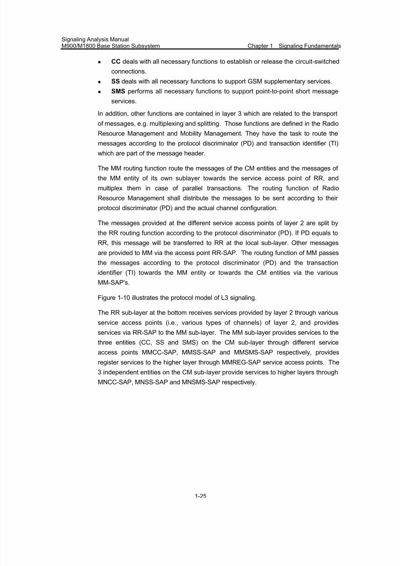
7/30/2019 Signaling Analysis Manual
http://slidepdf.com/reader/full/signaling-analysis-manual 40/290
Signaling Analysis ManualM900/M1800 Base Station Subsystem Chapter 1 Signaling Fundamentals
1-25
z CC deals with all necessary functions to establish or release the circuit-switched
connections.
z SS deals with all necessary functions to support GSM supplementary services.
z
SMS performs all necessary functions to support point-to-point short messageservices.
In addition, other functions are contained in layer 3 which are related to the transport
of messages, e.g. multiplexing and splitting. Those functions are defined in the Radio
Resource Management and Mobility Management. They have the task to route the
messages according to the protocol discriminator (PD) and transaction identifier (TI)
which are part of the message header.
The MM routing function route the messages of the CM entities and the messages of
the MM entity of its own sublayer towards the service access point of RR, and
multiplex them in case of parallel transactions. The routing function of RadioResource Management shall distribute the messages to be sent according to their
protocol discriminator (PD) and the actual channel configuration.
The messages provided at the different service access points of layer 2 are split by
the RR routing function according to the protocol discriminator (PD). If PD equals to
RR, this message will be transferred to RR at the local sub-layer. Other messages
are provided to MM via the access point RR-SAP. The routing function of MM passes
the messages according to the protocol discriminator (PD) and the transaction
identifier (TI) towards the MM entity or towards the CM entities via the various
MM-SAP's.
Figure 1-10 illustrates the protocol model of L3 signaling.
The RR sub-layer at the bottom receives services provided by layer 2 through various
service access points (i.e., various types of channels) of layer 2, and provides
services via RR-SAP to the MM sub-layer. The MM sub-layer provides services to the
three entities (CC, SS and SMS) on the CM sub-layer through different service
access points MMCC-SAP, MMSS-SAP and MMSMS-SAP respectively, provides
register services to the higher layer through MMREG-SAP service access points. The
3 independent entities on the CM sub-layer provide services to higher layers through
MNCC-SAP, MNSS-SAP and MNSMS-SAP respectively.
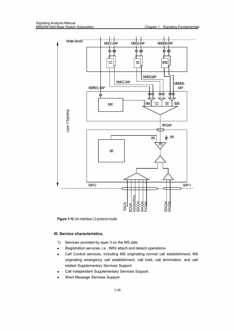
7/30/2019 Signaling Analysis Manual
http://slidepdf.com/reader/full/signaling-analysis-manual 41/290
Signaling Analysis ManualM900/M1800 Base Station Subsystem Chapter 1 Signaling Fundamentals
1-26
CC
MNCC-SAP
SS
MNSS-SAP
SMS
MNSMS-SAPMobile Service
MMREG -SAP
MMCC-SAP
MMSS-SAP
MMSMS-
SAP
MM CC SS SMSMM
RR-SAP
..RR
RR
PD
RR
SAPI 0 SAPI 3
R A C H
S D C C H
S A C C H
F A C C H
B C C H
S D C C H
S A C C H
A G C H + P C H
L a y e r 3 S i g n a l i n g
Figure 1-10 Um interface L3 protocol model
III. Service characteristics.
1) Services provided by layer 3 on the MS side
z Registration services, i.e., IMSI attach and detach operations.
z Call Control services, including MS originating normal call establishment, MS
originating emergency call establishment, call hold, call termination, and call
related Supplementary Services Support.
z Call independent Supplementary Services Support.
z Short Message Services Support.
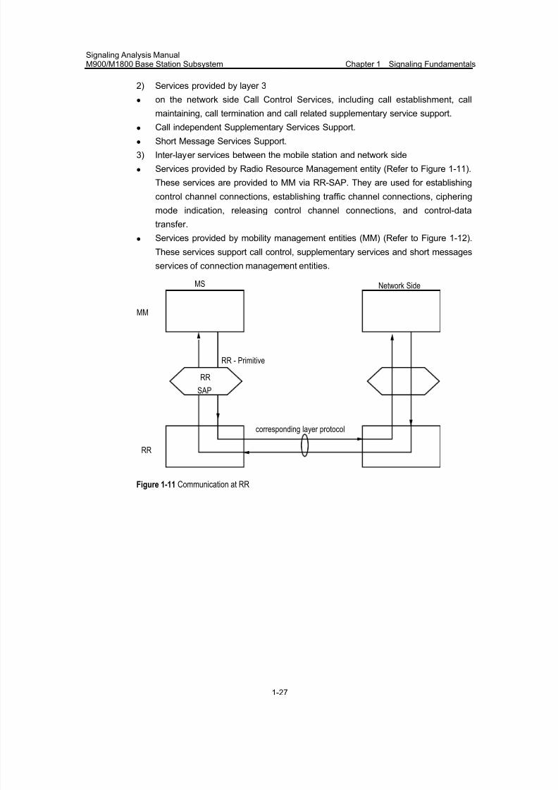
7/30/2019 Signaling Analysis Manual
http://slidepdf.com/reader/full/signaling-analysis-manual 42/290
Signaling Analysis ManualM900/M1800 Base Station Subsystem Chapter 1 Signaling Fundamentals
1-27
2) Services provided by layer 3
z on the network side Call Control Services, including call establishment, call
maintaining, call termination and call related supplementary service support.
z
Call independent Supplementary Services Support.
z Short Message Services Support.
3) Inter-layer services between the mobile station and network side
z Services provided by Radio Resource Management entity (Refer to Figure 1-11).
These services are provided to MM via RR-SAP. They are used for establishing
control channel connections, establishing traffic channel connections, ciphering
mode indication, releasing control channel connections, and control-data
transfer.
z Services provided by mobility management entities (MM) (Refer to Figure 1-12).
These services support call control, supplementary services and short messages
services of connection management entities.
RR
SAP
MS Network Side
MM
RR
RR - Primitive
corresponding layer protocol
Figure 1-11 Communication at RR
7/30/2019 Signaling Analysis Manual
http://slidepdf.com/reader/full/signaling-analysis-manual 43/290
Signaling Analysis ManualM900/M1800 Base Station Subsystem Chapter 1 Signaling Fundamentals
1-28
CC SMSS
MS
MM
CC SMSS
Network Side
MM
Corresponding layer protocol
Figure 1-12 Communication at MM
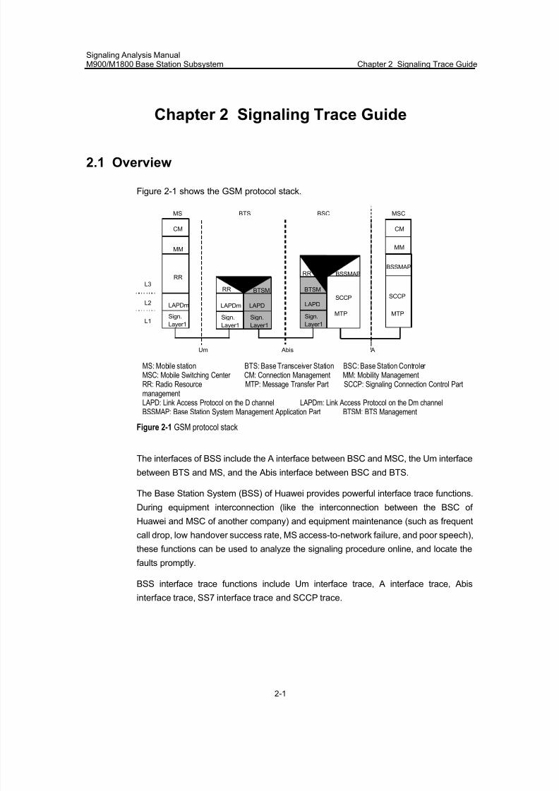
7/30/2019 Signaling Analysis Manual
http://slidepdf.com/reader/full/signaling-analysis-manual 44/290
Signaling Analysis ManualM900/M1800 Base Station Subsystem Chapter 2 Signaling Trace Guide
2-1
Chapter 2 Signaling Trace Guide
2.1 Overview
Figure 2-1 shows the GSM protocol stack.
CM
MM
RR
LAPDm
Sign.
Layer1
L3
L2
L1
BTSM
MS
Um
SCCP
MTP
BTSM
RR BSSMAP
Abis
BTS
BSC
MSC
A
BSC
Sign.
Layer1
Sign.
Layer1
Sign.
Layer1
RR
LAPDLAPDm LAPD
CM
MM
BSSMAP
SCCP
MTP
MS: Mobile station BTS: Base Transceiver Station BSC: Base Station Controler MSC: Mobile Switching Center CM: Connection Management MM: Mobility ManagementRR: Radio Resource
management
MTP: Message Transfer Part SCCP: Signaling Connection Control Part
LAPD: Link Access Protocol on the D channel LAPDm: Link Access Protocol on the Dm channelBSSMAP: Base Station System Management Application Part BTSM: BTS Management
Figure 2-1 GSM protocol stack
The interfaces of BSS include the A interface between BSC and MSC, the Um interface
between BTS and MS, and the Abis interface between BSC and BTS.
The Base Station System (BSS) of Huawei provides powerful interface trace functions.
During equipment interconnection (like the interconnection between the BSC of
Huawei and MSC of another company) and equipment maintenance (such as frequent
call drop, low handover success rate, MS access-to-network failure, and poor speech),
these functions can be used to analyze the signaling procedure online, and locate the
faults promptly.
BSS interface trace functions include Um interface trace, A interface trace, Abis
interface trace, SS7 interface trace and SCCP trace.
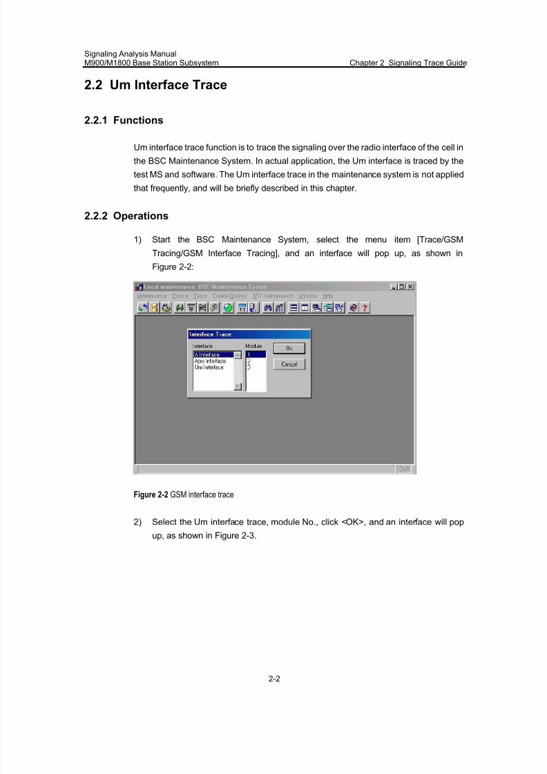
7/30/2019 Signaling Analysis Manual
http://slidepdf.com/reader/full/signaling-analysis-manual 45/290
Signaling Analysis ManualM900/M1800 Base Station Subsystem Chapter 2 Signaling Trace Guide
2-2
2.2 Um Interface Trace
2.2.1 Functions
Um interface trace function is to trace the signaling over the radio interface of the cell in
the BSC Maintenance System. In actual application, the Um interface is traced by the
test MS and software. The Um interface trace in the maintenance system is not applied
that frequently, and will be briefly described in this chapter.
2.2.2 Operations
1) Start the BSC Maintenance System, select the menu item [Trace/GSM
Tracing/GSM Interface Tracing], and an interface will pop up, as shown in
Figure 2-2:
Figure 2-2 GSM interface trace
2) Select the Um interface trace, module No., click <OK>, and an interface will pop
up, as shown in Figure 2-3.
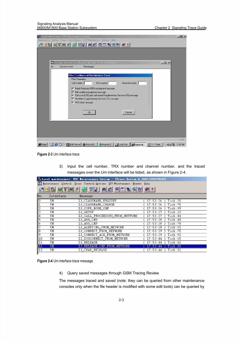
7/30/2019 Signaling Analysis Manual
http://slidepdf.com/reader/full/signaling-analysis-manual 46/290
Signaling Analysis ManualM900/M1800 Base Station Subsystem Chapter 2 Signaling Trace Guide
2-3
Figure 2-3 Um interface trace
3) Input the cell number, TRX number and channel number, and the traced
messages over the Um interface will be listed, as shown in Figure 2-4.
Figure 2-4 Um interface trace message
4) Query saved messages through GSM Tracing Review
The messages traced and saved (note: they can be queried from other maintenance
consoles only when the file header is modified with some edit tools) can be queried by
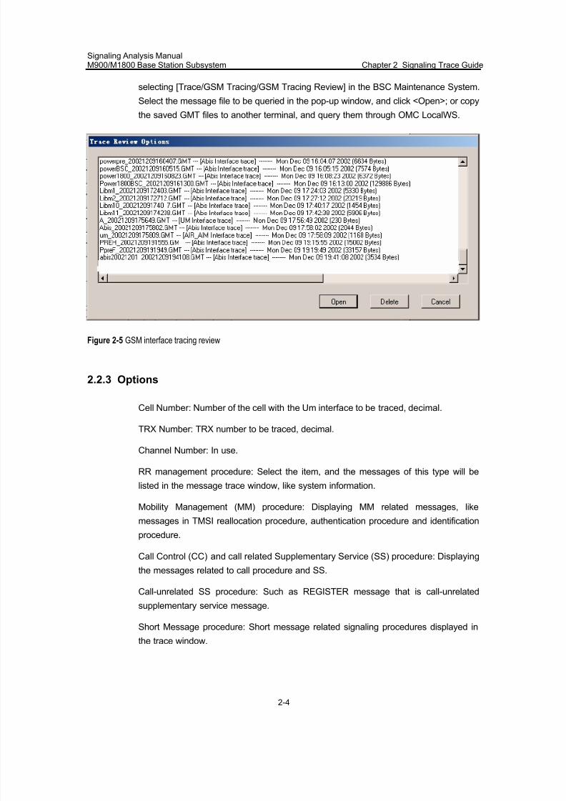
7/30/2019 Signaling Analysis Manual
http://slidepdf.com/reader/full/signaling-analysis-manual 47/290
Signaling Analysis ManualM900/M1800 Base Station Subsystem Chapter 2 Signaling Trace Guide
2-4
selecting [Trace/GSM Tracing/GSM Tracing Review] in the BSC Maintenance System.
Select the message file to be queried in the pop-up window, and click <Open>; or copy
the saved GMT files to another terminal, and query them through OMC LocalWS.
Figure 2-5 GSM interface tracing review
2.2.3 Options
Cell Number: Number of the cell with the Um interface to be traced, decimal.
TRX Number: TRX number to be traced, decimal.
Channel Number: In use.
RR management procedure: Select the item, and the messages of this type will be
listed in the message trace window, like system information.
Mobility Management (MM) procedure: Displaying MM related messages, like
messages in TMSI reallocation procedure, authentication procedure and identification
procedure.
Call Control (CC) and call related Supplementary Service (SS) procedure: Displaying
the messages related to call procedure and SS.
Call-unrelated SS procedure: Such as REGISTER message that is call-unrelated
supplementary service message.
Short Message procedure: Short message related signaling procedures displayed in
the trace window.
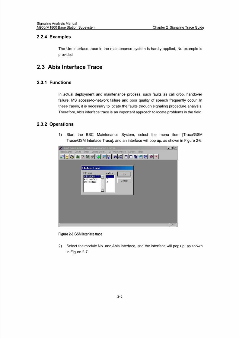
7/30/2019 Signaling Analysis Manual
http://slidepdf.com/reader/full/signaling-analysis-manual 48/290
Signaling Analysis ManualM900/M1800 Base Station Subsystem Chapter 2 Signaling Trace Guide
2-5
2.2.4 Examples
The Um interface trace in the maintenance system is hardly applied, No example is
provided
2.3 Abis Interface Trace
2.3.1 Functions
In actual deployment and maintenance process, such faults as call drop, handover
failure, MS access-to-network failure and poor quality of speech frequently occur. In
these cases, it is necessary to locate the faults through signaling procedure analysis.
Therefore, Abis interface trace is an important approach to locate problems in the field.
2.3.2 Operations
1) Start the BSC Maintenance System, select the menu item [Trace/GSM
Trace/GSM Interface Trace], and an interface will pop up, as shown in Figure 2-6.
Figure 2-6 GSM interface trace
2) Select the module No. and Abis interface, and the interface will pop up, as shown
in Figure 2-7.
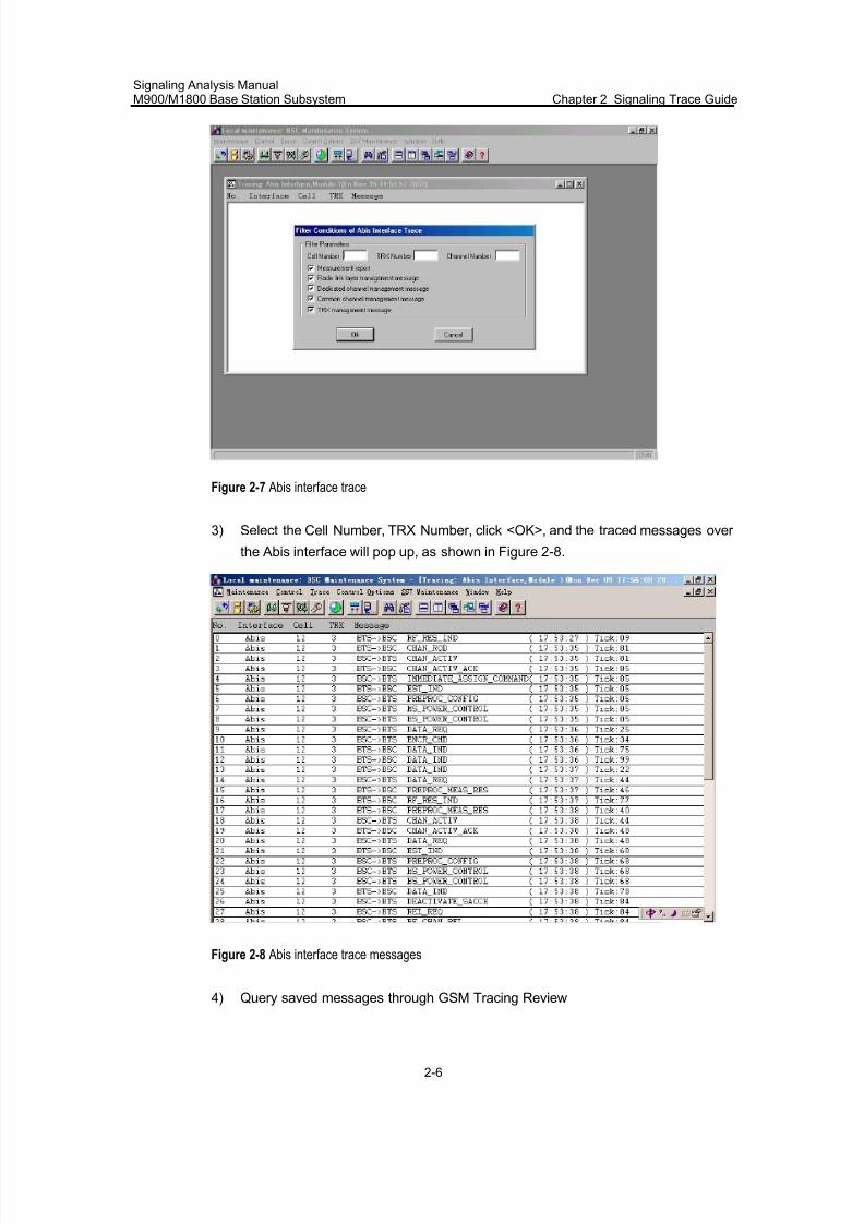
7/30/2019 Signaling Analysis Manual
http://slidepdf.com/reader/full/signaling-analysis-manual 49/290
Signaling Analysis ManualM900/M1800 Base Station Subsystem Chapter 2 Signaling Trace Guide
2-6
Figure 2-7 Abis interface trace
3) Select the Cell Number, TRX Number, click <OK>, and the traced messages over
the Abis interface will pop up, as shown in Figure 2-8.
Figure 2-8 Abis interface trace messages
4) Query saved messages through GSM Tracing Review
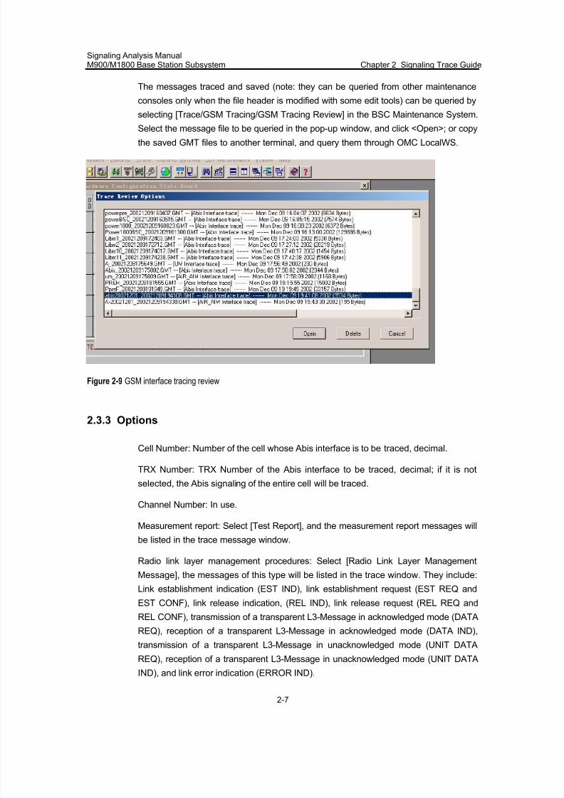
7/30/2019 Signaling Analysis Manual
http://slidepdf.com/reader/full/signaling-analysis-manual 50/290
Signaling Analysis ManualM900/M1800 Base Station Subsystem Chapter 2 Signaling Trace Guide
2-7
The messages traced and saved (note: they can be queried from other maintenance
consoles only when the file header is modified with some edit tools) can be queried by
selecting [Trace/GSM Tracing/GSM Tracing Review] in the BSC Maintenance System.
Select the message file to be queried in the pop-up window, and click <Open>; or copythe saved GMT files to another terminal, and query them through OMC LocalWS.
Figure 2-9 GSM interface tracing review
2.3.3 Options
Cell Number: Number of the cell whose Abis interface is to be traced, decimal.
TRX Number: TRX Number of the Abis interface to be traced, decimal; if it is not
selected, the Abis signaling of the entire cell will be traced.
Channel Number: In use.
Measurement report: Select [Test Report], and the measurement report messages will
be listed in the trace message window.
Radio link layer management procedures: Select [Radio Link Layer Management
Message], the messages of this type will be listed in the trace window. They include:
Link establishment indication (EST IND), link establishment request (EST REQ and
EST CONF), link release indication, (REL IND), link release request (REL REQ and
REL CONF), transmission of a transparent L3-Message in acknowledged mode (DATA
REQ), reception of a transparent L3-Message in acknowledged mode (DATA IND),
transmission of a transparent L3-Message in unacknowledged mode (UNIT DATA
REQ), reception of a transparent L3-Message in unacknowledged mode (UNIT DATA
IND), and link error indication (ERROR IND).
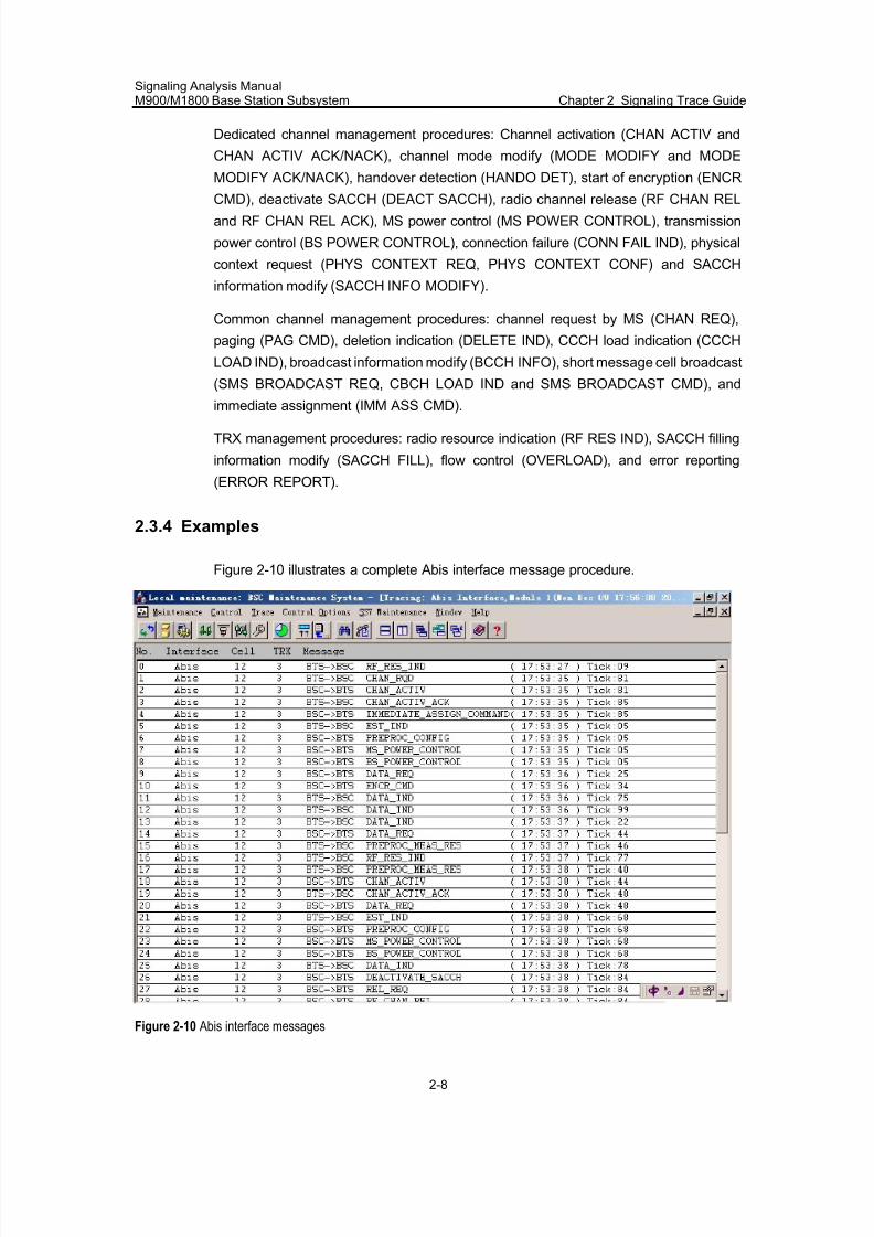
7/30/2019 Signaling Analysis Manual
http://slidepdf.com/reader/full/signaling-analysis-manual 51/290
Signaling Analysis ManualM900/M1800 Base Station Subsystem Chapter 2 Signaling Trace Guide
2-8
Dedicated channel management procedures: Channel activation (CHAN ACTIV and
CHAN ACTIV ACK/NACK), channel mode modify (MODE MODIFY and MODE
MODIFY ACK/NACK), handover detection (HANDO DET), start of encryption (ENCR
CMD), deactivate SACCH (DEACT SACCH), radio channel release (RF CHAN RELand RF CHAN REL ACK), MS power control (MS POWER CONTROL), transmission
power control (BS POWER CONTROL), connection failure (CONN FAIL IND), physical
context request (PHYS CONTEXT REQ, PHYS CONTEXT CONF) and SACCH
information modify (SACCH INFO MODIFY).
Common channel management procedures: channel request by MS (CHAN REQ),
paging (PAG CMD), deletion indication (DELETE IND), CCCH load indication (CCCH
LOAD IND), broadcast information modify (BCCH INFO), short message cell broadcast
(SMS BROADCAST REQ, CBCH LOAD IND and SMS BROADCAST CMD), and
immediate assignment (IMM ASS CMD).
TRX management procedures: radio resource indication (RF RES IND), SACCH filling
information modify (SACCH FILL), flow control (OVERLOAD), and error reporting
(ERROR REPORT).
2.3.4 Examples
Figure 2-10 illustrates a complete Abis interface message procedure.
Figure 2-10 Abis interface messages
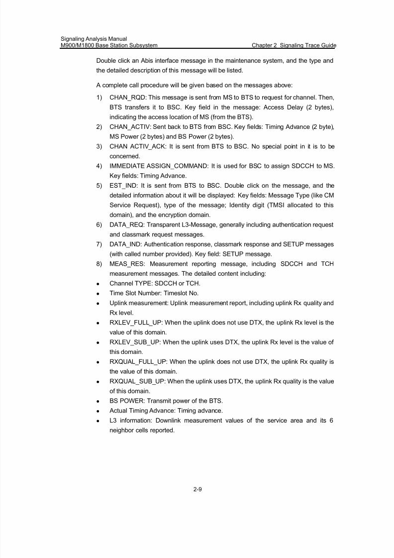
7/30/2019 Signaling Analysis Manual
http://slidepdf.com/reader/full/signaling-analysis-manual 52/290
Signaling Analysis ManualM900/M1800 Base Station Subsystem Chapter 2 Signaling Trace Guide
2-9
Double click an Abis interface message in the maintenance system, and the type and
the detailed description of this message will be listed.
A complete call procedure will be given based on the messages above:
1) CHAN_RQD: This message is sent from MS to BTS to request for channel. Then,
BTS transfers it to BSC. Key field in the message: Access Delay (2 bytes),
indicating the access location of MS (from the BTS).
2) CHAN_ACTIV: Sent back to BTS from BSC. Key fields: Timing Advance (2 byte),
MS Power (2 bytes) and BS Power (2 bytes).
3) CHAN ACTIV_ACK: It is sent from BTS to BSC. No special point in it is to be
concerned.
4) IMMEDIATE ASSIGN_COMMAND: It is used for BSC to assign SDCCH to MS.
Key fields: Timing Advance.
5) EST_IND: It is sent from BTS to BSC. Double click on the message, and thedetailed information about it will be displayed: Key fields: Message Type (like CM
Service Request), type of the message; Identity digit (TMSI allocated to this
domain), and the encryption domain.
6) DATA_REQ: Transparent L3-Message, generally including authentication request
and classmark request messages.
7) DATA_IND: Authentication response, classmark response and SETUP messages
(with called number provided). Key field: SETUP message.
8) MEAS_RES: Measurement reporting message, including SDCCH and TCH
measurement messages. The detailed content including:
z Channel TYPE: SDCCH or TCH.
z Time Slot Number: Timeslot No.
z Uplink measurement: Uplink measurement report, including uplink Rx quality and
Rx level.
z RXLEV_FULL_UP: When the uplink does not use DTX, the uplink Rx level is the
value of this domain.
z RXLEV_SUB_UP: When the uplink uses DTX, the uplink Rx level is the value of
this domain.
z RXQUAL_FULL_UP: When the uplink does not use DTX, the uplink Rx quality is
the value of this domain.z RXQUAL_SUB_UP: When the uplink uses DTX, the uplink Rx quality is the value
of this domain.
z BS POWER: Transmit power of the BTS.
z Actual Timing Advance: Timing advance.
z L3 information: Downlink measurement values of the service area and its 6
neighbor cells reported.
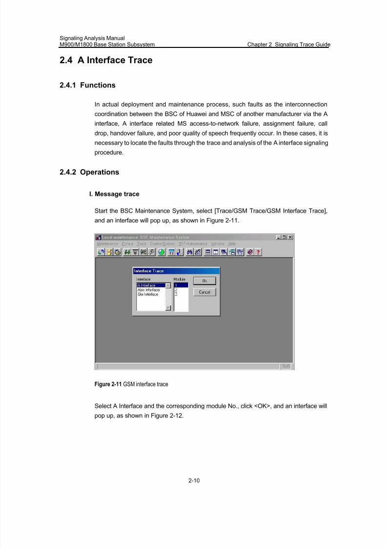
7/30/2019 Signaling Analysis Manual
http://slidepdf.com/reader/full/signaling-analysis-manual 53/290
Signaling Analysis ManualM900/M1800 Base Station Subsystem Chapter 2 Signaling Trace Guide
2-10
2.4 A Interface Trace
2.4.1 Functions
In actual deployment and maintenance process, such faults as the interconnection
coordination between the BSC of Huawei and MSC of another manufacturer via the A
interface, A interface related MS access-to-network failure, assignment failure, call
drop, handover failure, and poor quality of speech frequently occur. In these cases, it is
necessary to locate the faults through the trace and analysis of the A interface signaling
procedure.
2.4.2 Operations
I. Message trace
Start the BSC Maintenance System, select [Trace/GSM Trace/GSM Interface Trace],
and an interface will pop up, as shown in Figure 2-11.
Figure 2-11 GSM interface trace
Select A Interface and the corresponding module No., click <OK>, and an interface will
pop up, as shown in Figure 2-12.
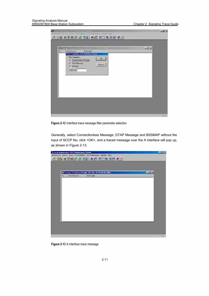
7/30/2019 Signaling Analysis Manual
http://slidepdf.com/reader/full/signaling-analysis-manual 54/290
Signaling Analysis ManualM900/M1800 Base Station Subsystem Chapter 2 Signaling Trace Guide
2-11
Figure 2-12 Interface trace message filter parameter selection
Generally, select Connectionless Message, DTAP Message and BSSMAP without the
input of SCCP No, click <OK>, and a traced message over the A interface will pop up,
as shown in Figure 2-13.
Figure 2-13 A interface trace message
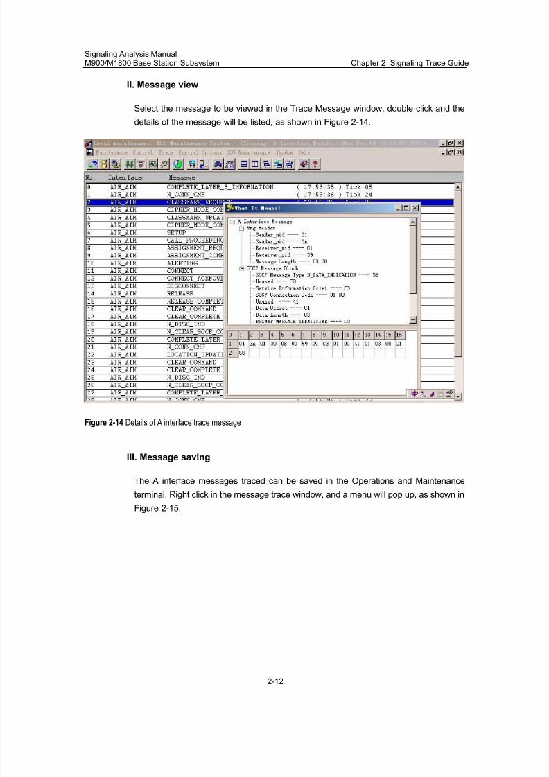
7/30/2019 Signaling Analysis Manual
http://slidepdf.com/reader/full/signaling-analysis-manual 55/290
Signaling Analysis ManualM900/M1800 Base Station Subsystem Chapter 2 Signaling Trace Guide
2-12
II. Message view
Select the message to be viewed in the Trace Message window, double click and the
details of the message will be listed, as shown in Figure 2-14.
Figure 2-14 Details of A interface trace message
III. Message saving
The A interface messages traced can be saved in the Operations and Maintenance
terminal. Right click in the message trace window, and a menu will pop up, as shown in
Figure 2-15.
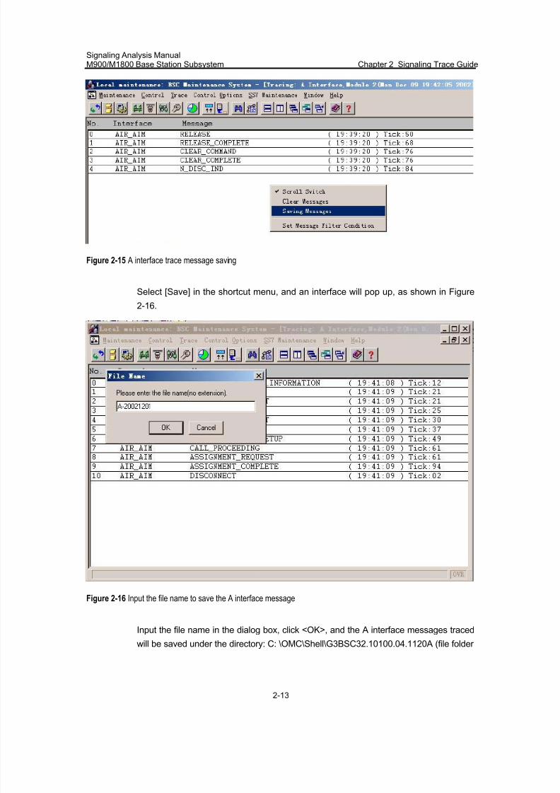
7/30/2019 Signaling Analysis Manual
http://slidepdf.com/reader/full/signaling-analysis-manual 56/290
Signaling Analysis ManualM900/M1800 Base Station Subsystem Chapter 2 Signaling Trace Guide
2-13
Figure 2-15 A interface trace message saving
Select [Save] in the shortcut menu, and an interface will pop up, as shown in Figure
2-16.
Figure 2-16 Input the file name to save the A interface message
Input the file name in the dialog box, click <OK>, and the A interface messages traced
will be saved under the directory: C: \OMC\Shell\G3BSC32.10100.04.1120A (file folder
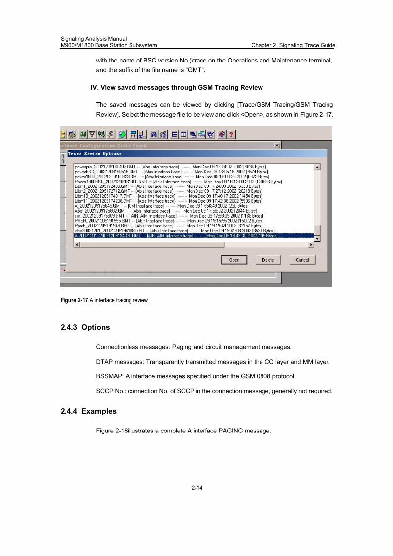
7/30/2019 Signaling Analysis Manual
http://slidepdf.com/reader/full/signaling-analysis-manual 57/290
Signaling Analysis ManualM900/M1800 Base Station Subsystem Chapter 2 Signaling Trace Guide
2-14
with the name of BSC version No.)\trace on the Operations and Maintenance terminal,
and the suffix of the file name is "GMT".
IV. View saved messages through GSM Tracing Review
The saved messages can be viewed by clicking [Trace/GSM Tracing/GSM Tracing
Review]. Select the message file to be view and click <Open>, as shown in Figure 2-17.
Figure 2-17 A interface tracing review
2.4.3 Options
Connectionless messages: Paging and circuit management messages.
DTAP messages: Transparently transmitted messages in the CC layer and MM layer.
BSSMAP: A interface messages specified under the GSM 0808 protocol.
SCCP No.: connection No. of SCCP in the connection message, generally not required.
2.4.4 Examples
Figure 2-18illustrates a complete A interface PAGING message.
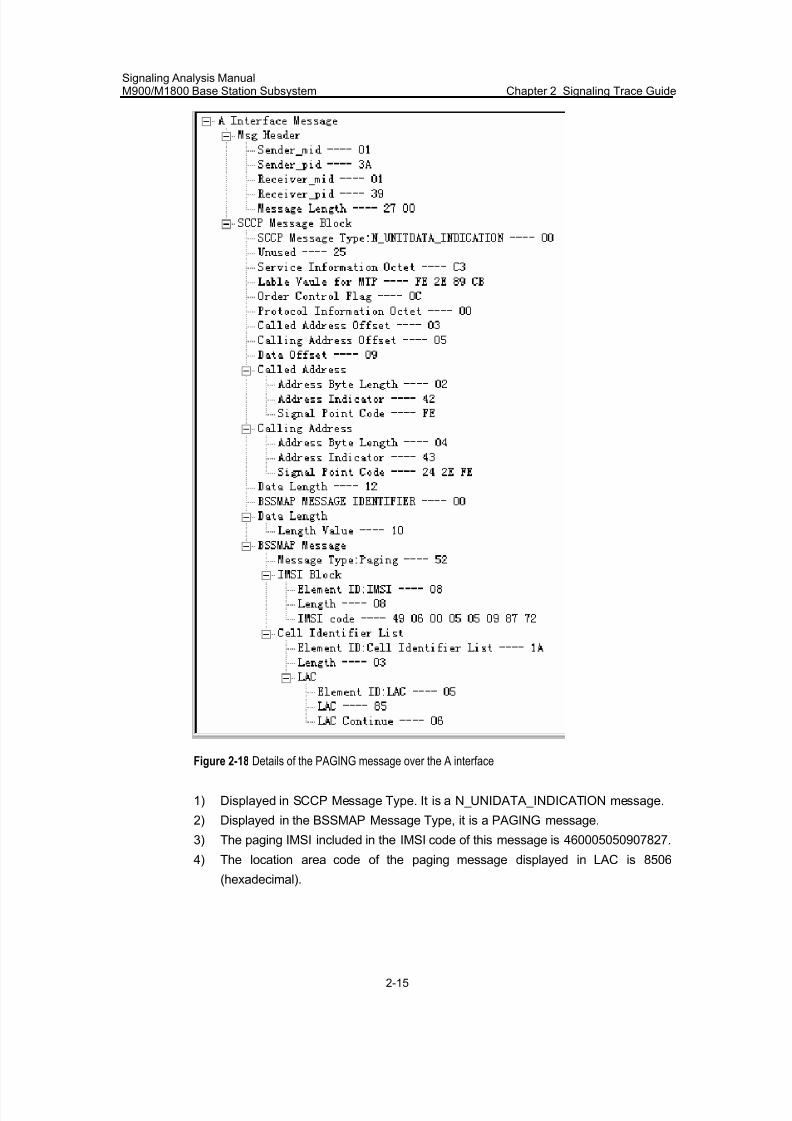
7/30/2019 Signaling Analysis Manual
http://slidepdf.com/reader/full/signaling-analysis-manual 58/290
Signaling Analysis ManualM900/M1800 Base Station Subsystem Chapter 2 Signaling Trace Guide
2-15
Figure 2-18 Details of the PAGING message over the A interface
1) Displayed in SCCP Message Type. It is a N_UNIDATA_INDICATION message.
2) Displayed in the BSSMAP Message Type, it is a PAGING message.
3) The paging IMSI included in the IMSI code of this message is 460005050907827.
4) The location area code of the paging message displayed in LAC is 8506
(hexadecimal).
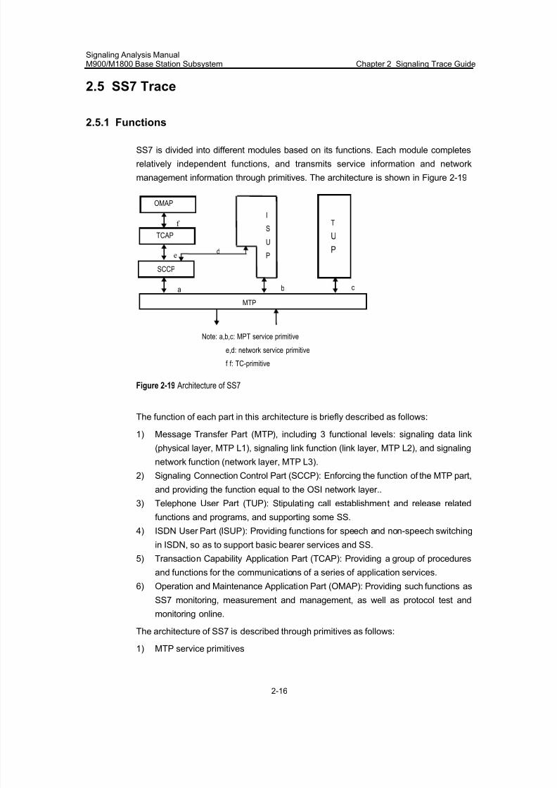
7/30/2019 Signaling Analysis Manual
http://slidepdf.com/reader/full/signaling-analysis-manual 59/290
Signaling Analysis ManualM900/M1800 Base Station Subsystem Chapter 2 Signaling Trace Guide
2-16
2.5 SS7 Trace
2.5.1 Functions
SS7 is divided into different modules based on its functions. Each module completes
relatively independent functions, and transmits service information and network
management information through primitives. The architecture is shown in Figure 2-19
OMAP
TCAP
SCCP
MTP
I
S
U
P
T
U
P
a b c
de
f
Note: a,b,c: MPT service primitive
e,d: network service primitive
f f: TC-primitive
Figure 2-19 Architecture of SS7
The function of each part in this architecture is briefly described as follows:
1) Message Transfer Part (MTP), including 3 functional levels: signaling data link
(physical layer, MTP L1), signaling link function (link layer, MTP L2), and signaling
network function (network layer, MTP L3).
2) Signaling Connection Control Part (SCCP): Enforcing the function of the MTP part,
and providing the function equal to the OSI network layer..
3) Telephone User Part (TUP): Stipulating call establishment and release related
functions and programs, and supporting some SS.
4) ISDN User Part (ISUP): Providing functions for speech and non-speech switching
in ISDN, so as to support basic bearer services and SS.
5) Transaction Capability Application Part (TCAP): Providing a group of procedures
and functions for the communications of a series of application services.
6) Operation and Maintenance Application Part (OMAP): Providing such functions as
SS7 monitoring, measurement and management, as well as protocol test and
monitoring online.
The architecture of SS7 is described through primitives as follows:
1) MTP service primitives
7/30/2019 Signaling Analysis Manual
http://slidepdf.com/reader/full/signaling-analysis-manual 60/290
Signaling Analysis ManualM900/M1800 Base Station Subsystem Chapter 2 Signaling Trace Guide
2-17
MTP_TRANSFER request: Used for SCCP to transfer signals and messages to MTP.
MTP_TRANSFER indication: Used for MTP to transfer signals and messages to SCCP.
MTP_PAUSE indication: Used for MTP to notify TUP that it cannot transfer themessage to the destination.
MTP_RESUME indication: Used for MTP to notify TUP that it is capable to provide MTP
services to the destination.
MTP_STATUS indication: Used for MTP to notify TUP that it can partially (congestion)
provide MPT services to the destination. It is also used to notify MS the cause whether
the remote MS is available or not.
MTP_RESTART indication: Upon the completion of MTP restart, it informs the local
MTP users of the end of the MTP restart, and indicates whether a signaling point isavailable nor not.
2) Network service primitives
Connectionless service primitives:
N_UNITDATA request: A SCCP user requests the SCCP to transmit data to another
SCCP.
N_UNITDATA indication: SCCP notifies users that the user data are sent to the
destination.
N_NOTICE indication: SCCP notifies the originating user that the message cannot be
sent to the destination.
Connection-oriented service primitives:
N_CONNECT request: The message from the calling SCCP User to SCCP is used to
start the connection establishment procedure to establish a signaling connection.
N_CONNECT indication: It is sent from SCCP to request the called SCCP User to
establish signaling connection with the calling MS.
N_CONNECT response: It is sent from SCCP to notify the called SCCP User that itagrees to establish signaling connection.
N_CONNECT acknowledgement: The calling SCCP notifies the calling MS to confirm
the establishment of the signaling connection.
N_DATA request: SCCP User requests SCCP to transfer data.
N_DATA indication: SCCP notifies the SCCP User that the user data have been sent to
the destination.
N_DISCONNECT request: SCCP User requests SCCP to reject or terminate the
signaling connection.
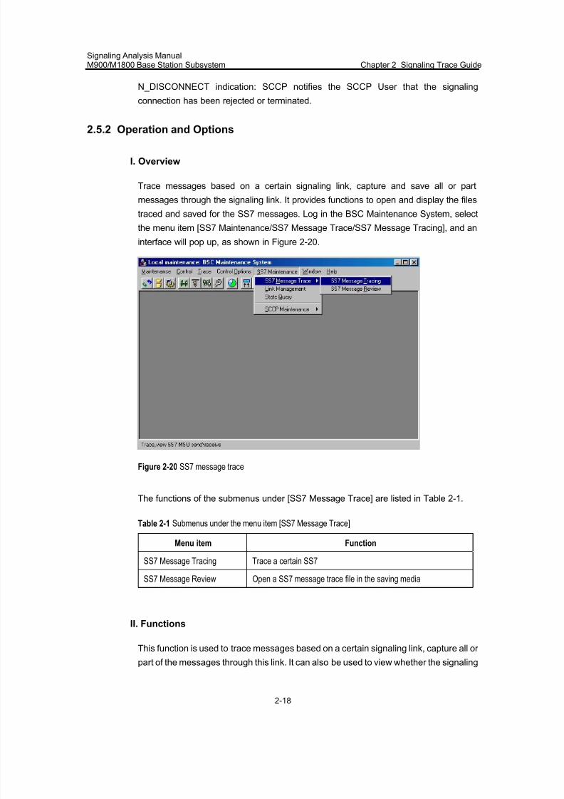
7/30/2019 Signaling Analysis Manual
http://slidepdf.com/reader/full/signaling-analysis-manual 61/290
Signaling Analysis ManualM900/M1800 Base Station Subsystem Chapter 2 Signaling Trace Guide
2-18
N_DISCONNECT indication: SCCP notifies the SCCP User that the signaling
connection has been rejected or terminated.
2.5.2 Operation and Options
I. Overview
Trace messages based on a certain signaling link, capture and save all or part
messages through the signaling link. It provides functions to open and display the files
traced and saved for the SS7 messages. Log in the BSC Maintenance System, select
the menu item [SS7 Maintenance/SS7 Message Trace/SS7 Message Tracing], and an
interface will pop up, as shown in Figure 2-20.
Figure 2-20 SS7 message trace
The functions of the submenus under [SS7 Message Trace] are listed in Table 2-1.
Table 2-1 Submenus under the menu item [SS7 Message Trace]
Menu item Function
SS7 Message Tracing Trace a certain SS7
SS7 Message Review Open a SS7 message trace file in the saving media
II. Functions
This function is used to trace messages based on a certain signaling link, capture all or
part of the messages through this link. It can also be used to view whether the signaling
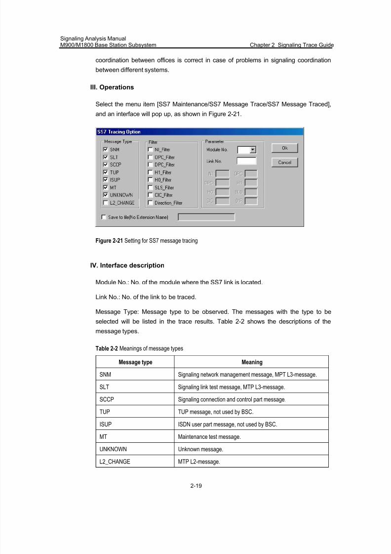
7/30/2019 Signaling Analysis Manual
http://slidepdf.com/reader/full/signaling-analysis-manual 62/290
Signaling Analysis ManualM900/M1800 Base Station Subsystem Chapter 2 Signaling Trace Guide
2-19
coordination between offices is correct in case of problems in signaling coordination
between different systems.
III. Operations
Select the menu item [SS7 Maintenance/SS7 Message Trace/SS7 Message Traced],
and an interface will pop up, as shown in Figure 2-21.
Figure 2-21 Setting for SS7 message tracing
IV. Interface description
Module No.: No. of the module where the SS7 link is located.
Link No.: No. of the link to be traced.
Message Type: Message type to be observed. The messages with the type to be
selected will be listed in the trace results. Table 2-2 shows the descriptions of the
message types.
Table 2-2 Meanings of message types
Message type Meaning
SNM Signaling network management message, MPT L3-message.
SLT Signaling link test message, MTP L3-message.
SCCP Signaling connection and control part message.
TUP TUP message, not used by BSC.
ISUP ISDN user part message, not used by BSC.
MT Maintenance test message.
UNKNOWN Unknown message.
L2_CHANGE MTP L2-message.
7/30/2019 Signaling Analysis Manual
http://slidepdf.com/reader/full/signaling-analysis-manual 63/290
Signaling Analysis ManualM900/M1800 Base Station Subsystem Chapter 2 Signaling Trace Guide
2-20
Filter: It is used to filter messages of the specified type. For instance, you can observe
a message sent to a signaling point by setting the value of DPC_Filter. Once a filter is
selected, the corresponding box in [Parameter] will become valid, and you can input the
specified value. Table 2-3 shows the details of the filters.
Table 2-3 Meanings of filters
Filter Meaning
NI_Filter Network indicator (NI) filter: International-0, international reserved-1, national –2and national reserved-3.
OPC_Filter Original signaling point code (OPC) filter: The OPC value is required.
DPC_Filter Destination signaling point code (DPC) filter: The DPC value is required.
H1_Filter H1 filter in MSU.
H0_Filter H0 filter in MSU (the specified messages can be filtered by setting both filters H1and H0).
SLS_Filter Signaling link selection (SLS) code filter: SLS value is required.
CIC_Filter Circuit identification code filter: CIC value is required.
Direction_Filter Signaling direction filter: 0 for Tx; 1 for Rx.
If the user selects the check box "Save to file (No Extension Name)", and inputs the file
name (without suffix) in the text box, the system will trace the information and save it for
future review and analysis.
After setting all the trace items, click the <OK> button to start tracing. If an item is not
set correctly, e.g., to trace a link actually not installed, the system will prompt "Sorry.
Tracing MSU failed".
If the trace item is correctly set, a window shown in Figure 2-23 will pop up, indicating
the start of trace.
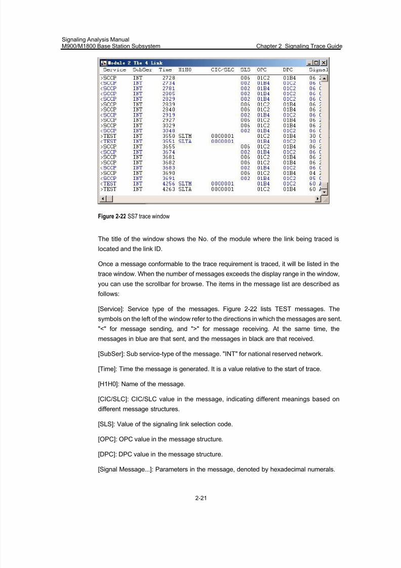
7/30/2019 Signaling Analysis Manual
http://slidepdf.com/reader/full/signaling-analysis-manual 64/290
Signaling Analysis ManualM900/M1800 Base Station Subsystem Chapter 2 Signaling Trace Guide
2-21
Figure 2-22 SS7 trace window
The title of the window shows the No. of the module where the link being traced is
located and the link ID.
Once a message conformable to the trace requirement is traced, it will be listed in the
trace window. When the number of messages exceeds the display range in the window,
you can use the scrollbar for browse. The items in the message list are described asfollows:
[Service]: Service type of the messages. Figure 2-22 lists TEST messages. The
symbols on the left of the window refer to the directions in which the messages are sent.
"<" for message sending, and ">" for message receiving. At the same time, the
messages in blue are that sent, and the messages in black are that received.
[SubSer]: Sub service-type of the message. "INT" for national reserved network.
[Time]: Time the message is generated. It is a value relative to the start of trace.
[H1H0]: Name of the message.
[CIC/SLC]: CIC/SLC value in the message, indicating different meanings based on
different message structures.
[SLS]: Value of the signaling link selection code.
[OPC]: OPC value in the message structure.
[DPC]: DPC value in the message structure.
[Signal Message...]: Parameters in the message, denoted by hexadecimal numerals.
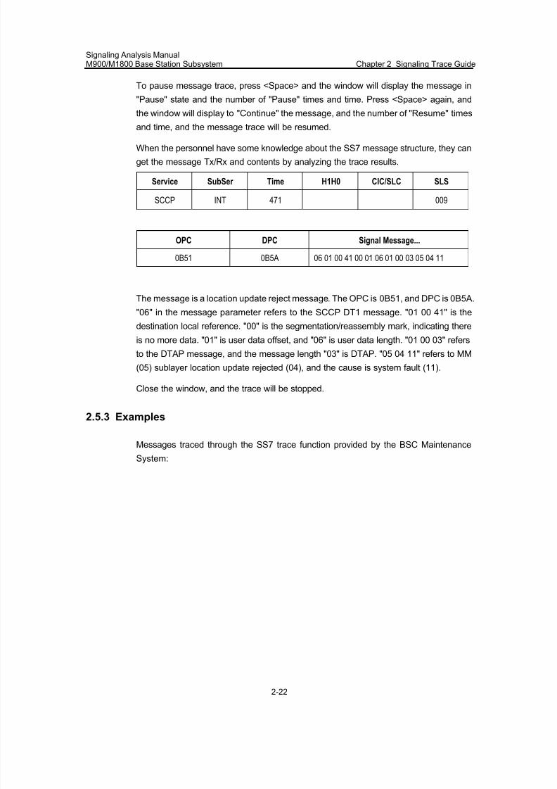
7/30/2019 Signaling Analysis Manual
http://slidepdf.com/reader/full/signaling-analysis-manual 65/290
Signaling Analysis ManualM900/M1800 Base Station Subsystem Chapter 2 Signaling Trace Guide
2-22
To pause message trace, press <Space> and the window will display the message in
"Pause" state and the number of "Pause" times and time. Press <Space> again, and
the window will display to "Continue" the message, and the number of "Resume" times
and time, and the message trace will be resumed.
When the personnel have some knowledge about the SS7 message structure, they can
get the message Tx/Rx and contents by analyzing the trace results.
Service SubSer Time H1H0 CIC/SLC SLS
SCCP INT 471 009
OPC DPC Signal Message...
0B51 0B5A 06 01 00 41 00 01 06 01 00 03 05 04 11
The message is a location update reject message. The OPC is 0B51, and DPC is 0B5A.
"06" in the message parameter refers to the SCCP DT1 message. "01 00 41" is the
destination local reference. "00" is the segmentation/reassembly mark, indicating there
is no more data. "01" is user data offset, and "06" is user data length. "01 00 03" refers
to the DTAP message, and the message length "03" is DTAP. "05 04 11" refers to MM
(05) sublayer location update rejected (04), and the cause is system fault (11).
Close the window, and the trace will be stopped.
2.5.3 Examples
Messages traced through the SS7 trace function provided by the BSC Maintenance
System:
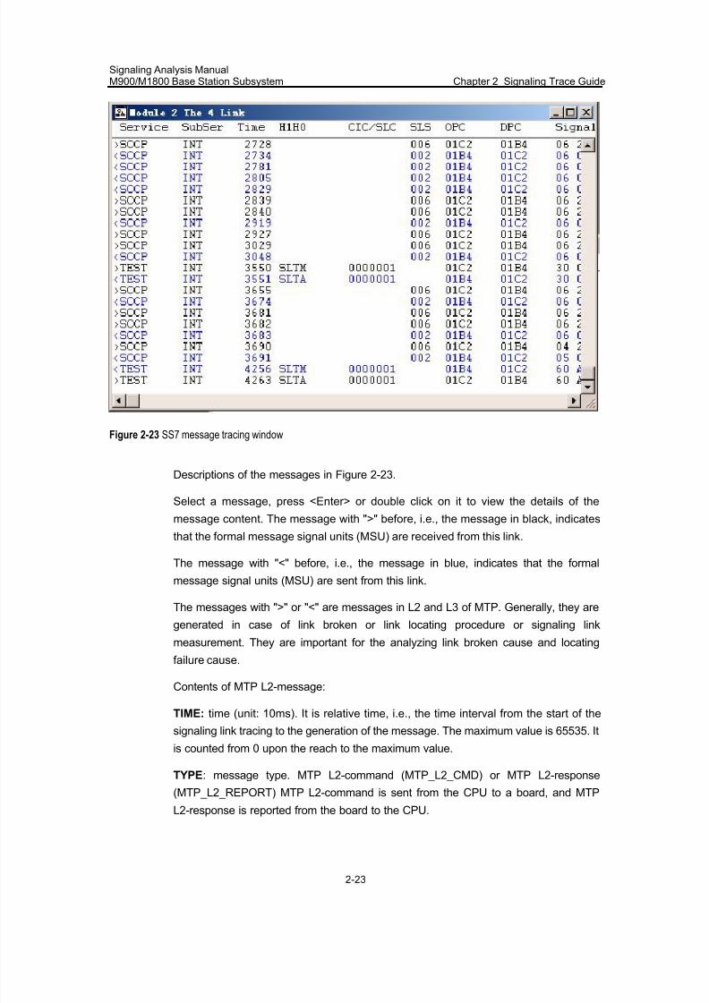
7/30/2019 Signaling Analysis Manual
http://slidepdf.com/reader/full/signaling-analysis-manual 66/290
Signaling Analysis ManualM900/M1800 Base Station Subsystem Chapter 2 Signaling Trace Guide
2-23
Figure 2-23 SS7 message tracing window
Descriptions of the messages in Figure 2-23.
Select a message, press <Enter> or double click on it to view the details of themessage content. The message with ">" before, i.e., the message in black, indicates
that the formal message signal units (MSU) are received from this link.
The message with "<" before, i.e., the message in blue, indicates that the formal
message signal units (MSU) are sent from this link.
The messages with ">" or "<" are messages in L2 and L3 of MTP. Generally, they are
generated in case of link broken or link locating procedure or signaling link
measurement. They are important for the analyzing link broken cause and locating
failure cause.
Contents of MTP L2-message:
TIME: time (unit: 10ms). It is relative time, i.e., the time interval from the start of the
signaling link tracing to the generation of the message. The maximum value is 65535. It
is counted from 0 upon the reach to the maximum value.
TYPE: message type. MTP L2-command (MTP_L2_CMD) or MTP L2-response
(MTP_L2_REPORT) MTP L2-command is sent from the CPU to a board, and MTP
L2-response is reported from the board to the CPU.
7/30/2019 Signaling Analysis Manual
http://slidepdf.com/reader/full/signaling-analysis-manual 67/290
Signaling Analysis ManualM900/M1800 Base Station Subsystem Chapter 2 Signaling Trace Guide
2-24
PARA: Command or response parameter. It refers to a board type. 00 is for the LPN7
board, and 01 for SS7 board. The parameters followed are commands or command
responses, please refer to the details of the messages.
Note:
Only the content following PARA is used in the examples for the messages of this type.
The first message in the "SS7 Message Tracing window" can be briefly described as
follows: In the 19.7th second since the opening of the message tracing window, MTP
delivers a STOP command to this signaling link.
MSU transmitted in the link:
Service: Service indication of the message. Test refers to signaling link test messages,
MPT refers to the signaling network management messages in MTP, and TUP, ISUP
and SCCP refer to the messages in TUP, ISUP and SCCP respectively.
SubSer : Sub service field, i.e., NI. NAT is for national network, and INT for international
network.
Time: time (unit: 10ms), it is a relative time, i.e., the time interval from the start of the
signaling link trace to the generation of the message. The maximum value is 65535. Itis counted from 0 upon the reach to the maximum value.
H1H0: Message header code, used to identify a specific message.
CIC/SLC: CIC for the TUP and ISUP messages, SLC for the MTP messages, and SLS
for the SCCP messages.
SLS: Signaling link selection code. It is displayed for the ISUP messages only.
OPC: Originating signaling point code in the message.
DPC: Destination signaling point code in the message.
Signal Message: Contents of the message.
2.6 SCCP Signaling Trace
2.6.1 Functions
SCCP, signaling connection control part in SS7, is an important approach to locate and
solve problems in deployment, maintenance and debugging. The OMC of Huawei
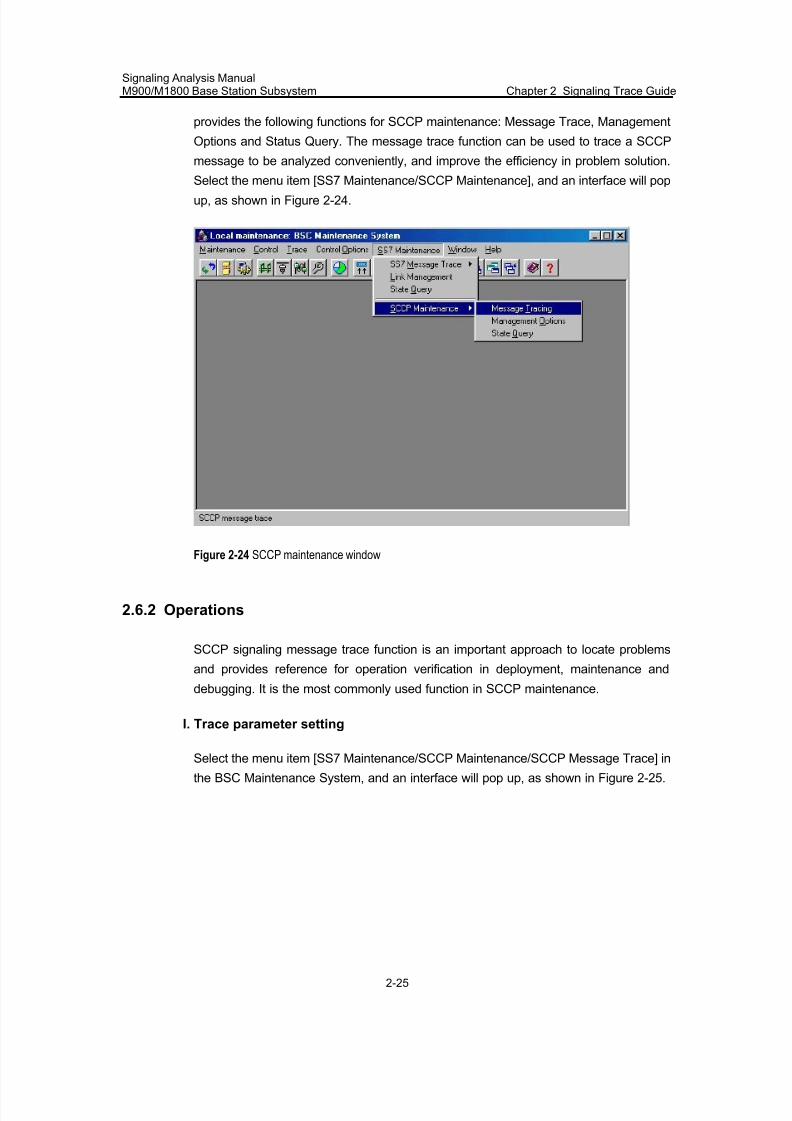
7/30/2019 Signaling Analysis Manual
http://slidepdf.com/reader/full/signaling-analysis-manual 68/290
Signaling Analysis ManualM900/M1800 Base Station Subsystem Chapter 2 Signaling Trace Guide
2-25
provides the following functions for SCCP maintenance: Message Trace, Management
Options and Status Query. The message trace function can be used to trace a SCCP
message to be analyzed conveniently, and improve the efficiency in problem solution.
Select the menu item [SS7 Maintenance/SCCP Maintenance], and an interface will popup, as shown in Figure 2-24.
Figure 2-24 SCCP maintenance window
2.6.2 Operations
SCCP signaling message trace function is an important approach to locate problems
and provides reference for operation verification in deployment, maintenance and
debugging. It is the most commonly used function in SCCP maintenance.
I. Trace parameter setting
Select the menu item [SS7 Maintenance/SCCP Maintenance/SCCP Message Trace] in
the BSC Maintenance System, and an interface will pop up, as shown in Figure 2-25.
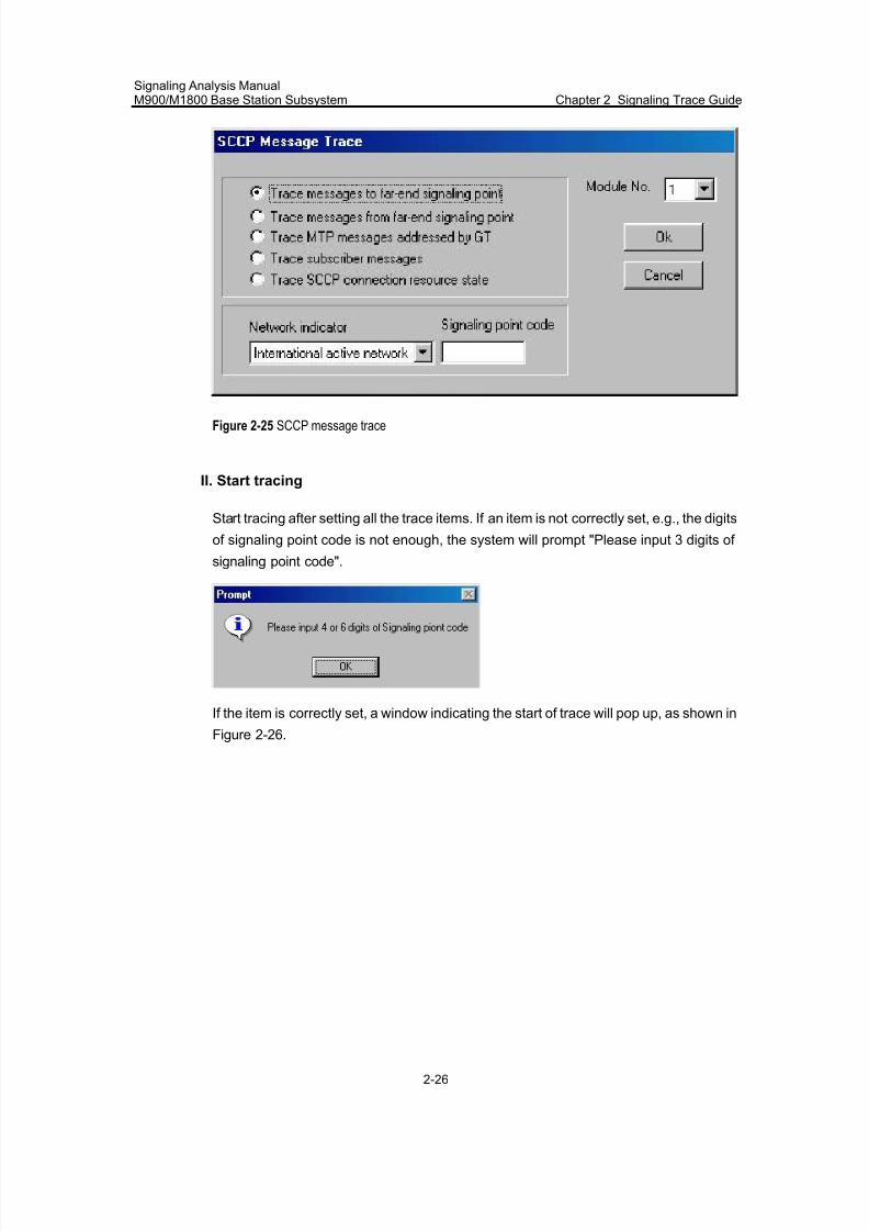
7/30/2019 Signaling Analysis Manual
http://slidepdf.com/reader/full/signaling-analysis-manual 69/290
Signaling Analysis ManualM900/M1800 Base Station Subsystem Chapter 2 Signaling Trace Guide
2-26
Figure 2-25 SCCP message trace
II. Start tracing
Start tracing after setting all the trace items. If an item is not correctly set, e.g., the digits
of signaling point code is not enough, the system will prompt "Please input 3 digits of
signaling point code".
If the item is correctly set, a window indicating the start of trace will pop up, as shown in
Figure 2-26.
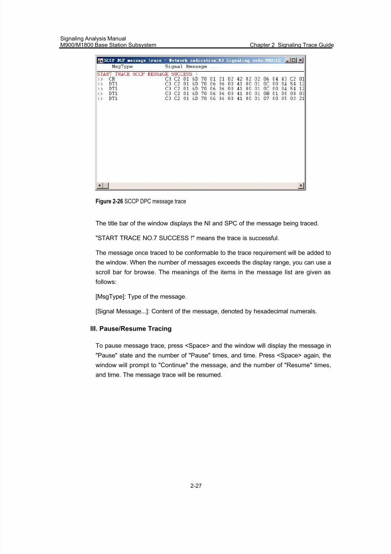
7/30/2019 Signaling Analysis Manual
http://slidepdf.com/reader/full/signaling-analysis-manual 70/290
Signaling Analysis ManualM900/M1800 Base Station Subsystem Chapter 2 Signaling Trace Guide
2-27
Figure 2-26 SCCP DPC message trace
The title bar of the window displays the NI and SPC of the message being traced.
"START TRACE NO.7 SUCCESS !" means the trace is successful.
The message once traced to be conformable to the trace requirement will be added to
the window. When the number of messages exceeds the display range, you can use a
scroll bar for browse. The meanings of the items in the message list are given as
follows:
[MsgType]: Type of the message.
[Signal Message...]: Content of the message, denoted by hexadecimal numerals.
III. Pause/Resume Tracing
To pause message trace, press <Space> and the window will display the message in
"Pause" state and the number of "Pause" times, and time. Press <Space> again, the
window will prompt to "Continue" the message, and the number of "Resume" times,
and time. The message trace will be resumed.
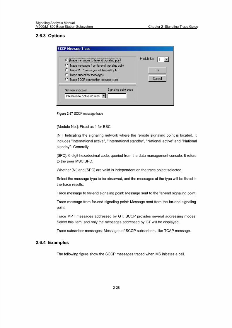
7/30/2019 Signaling Analysis Manual
http://slidepdf.com/reader/full/signaling-analysis-manual 71/290
Signaling Analysis ManualM900/M1800 Base Station Subsystem Chapter 2 Signaling Trace Guide
2-28
2.6.3 Options
Figure 2-27 SCCP message trace
[Module No.]: Fixed as 1 for BSC.
[NI]: Indicating the signaling network where the remote signaling point is located. It
includes "International active", "International standby", "National active" and "National
standby". Generally
[SPC]: 6-digit hexadecimal code, queried from the data management console. It refers
to the peer MSC SPC.
Whether [NI] and [SPC] are valid is independent on the trace object selected.
Select the message type to be observed, and the messages of the type will be listed in
the trace results.
Trace message to far-end signaling point: Message sent to the far-end signaling point.
Trace message from far-end signaling point: Message sent from the far-end signaling
point.
Trace MPT messages addressed by GT: SCCP provides several addressing modes.
Select this item, and only the messages addressed by GT will be displayed.
Trace subscriber messages: Messages of SCCP subscribers, like TCAP message.
2.6.4 Examples
The following figure show the SCCP messages traced when MS initiates a call.
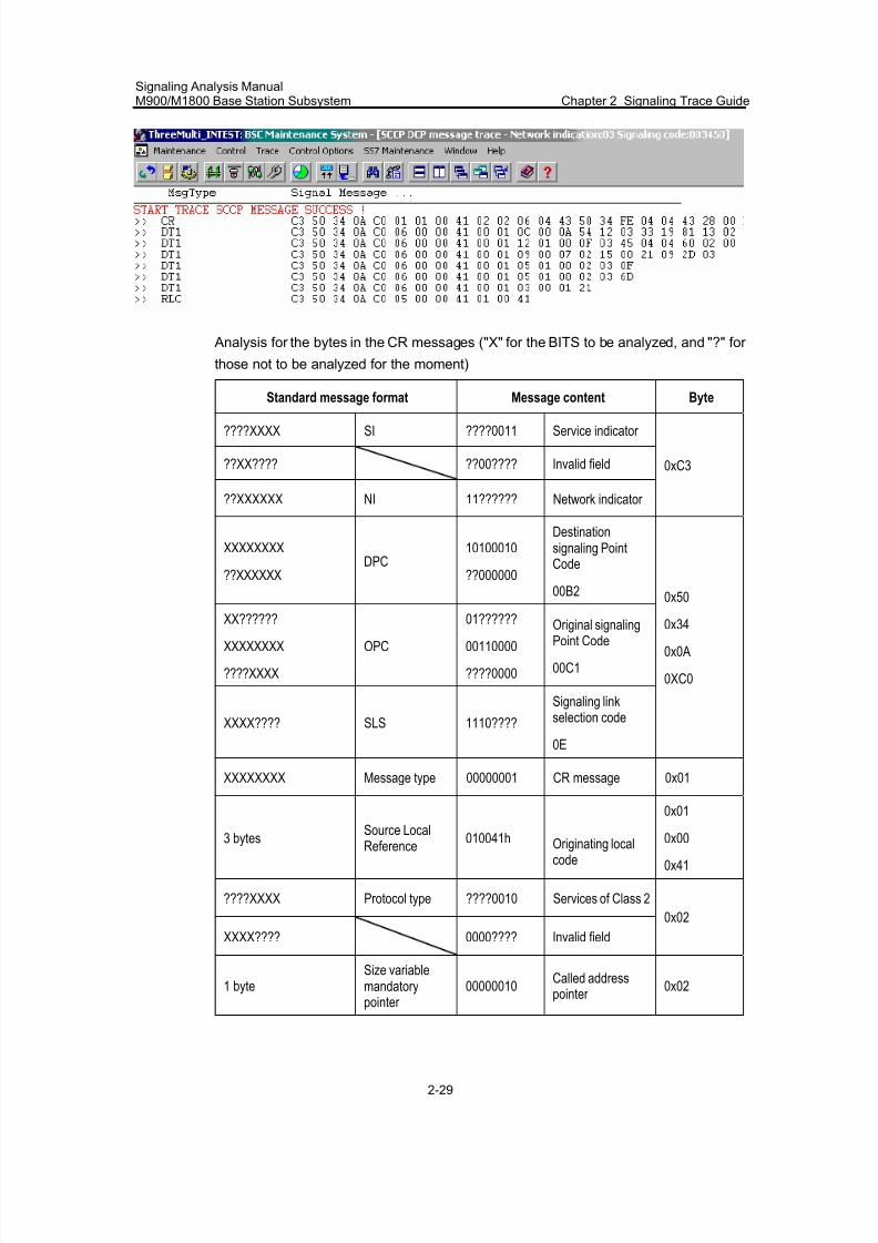
7/30/2019 Signaling Analysis Manual
http://slidepdf.com/reader/full/signaling-analysis-manual 72/290
Signaling Analysis ManualM900/M1800 Base Station Subsystem Chapter 2 Signaling Trace Guide
2-29
Analysis for the bytes in the CR messages ("X" for the BITS to be analyzed, and "?" for
those not to be analyzed for the moment)
Standard message format Message content Byte
????XXXX SI ????0011 Service indicator
??XX???? ??00???? Invalid field
??XXXXXX NI 11?????? Network indicator
0xC3
XXXXXXXX
??XXXXXXDPC
10100010
??000000
Destinationsignaling PointCode
00B2
XX??????
XXXXXXXX
????XXXX
OPC
01??????
00110000
????0000
Original signalingPoint Code
00C1
XXXX???? SLS 1110????
Signaling linkselection code
0E
0x50
0x34
0x0A
0XC0
XXXXXXXX Message type 00000001 CR message 0x01
3 bytes Source LocalReference
010041h Originating localcode
0x01
0x00
0x41
????XXXX Protocol type ????0010 Services of Class 2
XXXX???? 0000???? Invalid field
0x02
1 byteSize variablemandatorypointer
00000010Called addresspointer
0x02
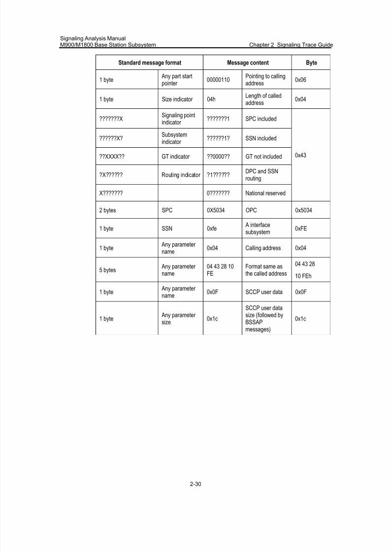
7/30/2019 Signaling Analysis Manual
http://slidepdf.com/reader/full/signaling-analysis-manual 73/290
Signaling Analysis ManualM900/M1800 Base Station Subsystem Chapter 2 Signaling Trace Guide
2-30
Standard message format Message content Byte
1 byte Any part startpointer
00000110Pointing to callingaddress
0x06
1 byte Size indicator 04hLength of calledaddress
0x04
???????XSignaling pointindicator
???????1 SPC included
??????X?Subsystemindicator
??????1? SSN included
??XXXX?? GT indicator ??0000?? GT not included
?X?????? Routing indicator ?1??????DPC and SSNrouting
X??????? 0??????? National reserved
0x43
2 bytes SPC 0X5034 OPC 0x5034
1 byte SSN 0xfe A interfacesubsystem
0xFE
1 byte Any parameter name
0x04 Calling address 0x04
5 bytes Any parameter
name
04 43 28 10
FE
Format same as
the called address
04 43 28
10 FEh
1 byte Any parameter name
0x0F SCCP user data 0x0F
1 byte Any parameter size
0x1c
SCCP user datasize (followed byBSSAPmessages)
0x1c
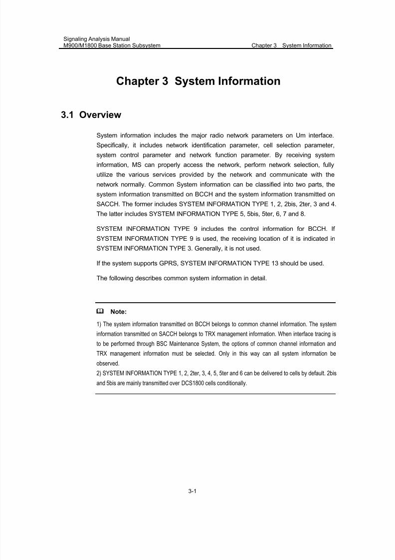
7/30/2019 Signaling Analysis Manual
http://slidepdf.com/reader/full/signaling-analysis-manual 74/290
Signaling Analysis ManualM900/M1800 Base Station Subsystem Chapter 3 System Information
3-1
Chapter 3 System Information
3.1 Overview
System information includes the major radio network parameters on Um interface.
Specifically, it includes network identification parameter, cell selection parameter,
system control parameter and network function parameter. By receiving system
information, MS can properly access the network, perform network selection, fully
utilize the various services provided by the network and communicate with the
network normally. Common System information can be classified into two parts, thesystem information transmitted on BCCH and the system information transmitted on
SACCH. The former includes SYSTEM INFORMATION TYPE 1, 2, 2bis, 2ter, 3 and 4.
The latter includes SYSTEM INFORMATION TYPE 5, 5bis, 5ter, 6, 7 and 8.
SYSTEM INFORMATION TYPE 9 includes the control information for BCCH. If
SYSTEM INFORMATION TYPE 9 is used, the receiving location of it is indicated in
SYSTEM INFORMATION TYPE 3. Generally, it is not used.
If the system supports GPRS, SYSTEM INFORMATION TYPE 13 should be used.
The following describes common system information in detail.
Note:
1) The system information transmitted on BCCH belongs to common channel information. The system
information transmitted on SACCH belongs to TRX management information. When interface tracing is
to be performed through BSC Maintenance System, the options of common channel information and
TRX management information must be selected. Only in this way can all system information be
observed.
2) SYSTEM INFORMATION TYPE 1, 2, 2ter, 3, 4, 5, 5ter and 6 can be delivered to cells by default. 2bisand 5bis are mainly transmitted over DCS1800 cells conditionally.
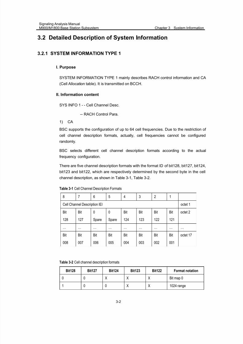
7/30/2019 Signaling Analysis Manual
http://slidepdf.com/reader/full/signaling-analysis-manual 75/290
Signaling Analysis ManualM900/M1800 Base Station Subsystem Chapter 3 System Information
3-2
3.2 Detailed Description of System Information
3.2.1 SYSTEM INFORMATION TYPE 1
I. Purpose
SYSTEM INFORMATION TYPE 1 mainly describes RACH control information and CA
(Cell Allocation table). It is transmitted on BCCH.
II. Information content
SYS INFO 1 - - Cell Channel Desc.
-- RACH Control Para.
1) CA
BSC supports the configuration of up to 64 cell frequencies. Due to the restriction of
cell channel description formats, actually, cell frequencies cannot be configured
randomly.
BSC selects different cell channel description formats according to the actual
frequency configuration.
There are five channel description formats with the format ID of bit128, bit127, bit124,
bit123 and bit122, which are respectively determined by the second byte in the cellchannel description, as shown in Table 3-1, Table 3-2.
Table 3-1 Cell Channel Description Formats
8 7 6 5 4 3 2 1
Cell Channel Description IEI octet 1
Bit
128
Bit
127
0
Spare
0
Spare
Bit
124
Bit
123
Bit
122
Bit
121
octet 2
… … … … … … … … …
Bit
008
Bit
007
Bit
006
Bit
005
Bit
004
Bit
003
Bit
002
Bit
001
octet 17
Table 3-2 Cell channel description formats
Bit128 Bit127 Bit124 Bit123 Bit122 Format notation
0 0 X X X Bit map 0
1 0 0 X X 1024 range
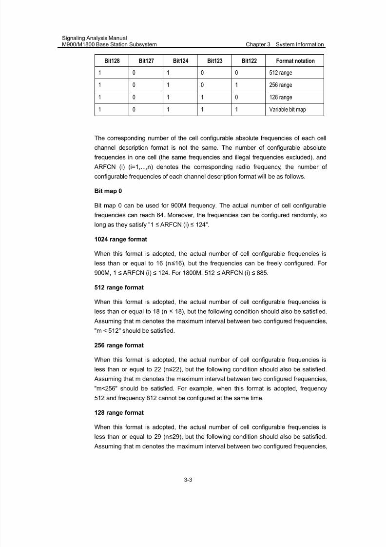
7/30/2019 Signaling Analysis Manual
http://slidepdf.com/reader/full/signaling-analysis-manual 76/290
Signaling Analysis ManualM900/M1800 Base Station Subsystem Chapter 3 System Information
3-3
Bit128 Bit127 Bit124 Bit123 Bit122 Format notation
1 0 1 0 0 512 range
1 0 1 0 1 256 range
1 0 1 1 0 128 range
1 0 1 1 1 Variable bit map
The corresponding number of the cell configurable absolute frequencies of each cell
channel description format is not the same. The number of configurable absolute
frequencies in one cell (the same frequencies and illegal frequencies excluded), and
ARFCN (i) (i=1,...,n) denotes the corresponding radio frequency, the number of
configurable frequencies of each channel description format will be as follows.
Bit map 0
Bit map 0 can be used for 900M frequency. The actual number of cell configurable
frequencies can reach 64. Moreover, the frequencies can be configured randomly, so
long as they satisfy "1 ≤ ARFCN (i) ≤ 124".
1024 range format
When this format is adopted, the actual number of cell configurable frequencies is
less than or equal to 16 (n≤16), but the frequencies can be freely configured. For
900M, 1 ≤ ARFCN (i) ≤ 124. For 1800M, 512 ≤ ARFCN (i) ≤ 885.
512 range format
When this format is adopted, the actual number of cell configurable frequencies is
less than or equal to 18 (n ≤ 18), but the following condition should also be satisfied.
Assuming that m denotes the maximum interval between two configured frequencies,
"m < 512" should be satisfied.
256 range format
When this format is adopted, the actual number of cell configurable frequencies is
less than or equal to 22 (n≤22), but the following condition should also be satisfied.
Assuming that m denotes the maximum interval between two configured frequencies,
"m<256" should be satisfied. For example, when this format is adopted, frequency
512 and frequency 812 cannot be configured at the same time.
128 range format
When this format is adopted, the actual number of cell configurable frequencies is
less than or equal to 29 (n≤29), but the following condition should also be satisfied.
Assuming that m denotes the maximum interval between two configured frequencies,
7/30/2019 Signaling Analysis Manual
http://slidepdf.com/reader/full/signaling-analysis-manual 77/290
Signaling Analysis ManualM900/M1800 Base Station Subsystem Chapter 3 System Information
3-4
"m<128" should be satisfied. For example, when this format is adopted, frequency
512 and frequency 712 cannot be configured at the same time.
Variable bit map
When this format is adopted, the actual number of cell configurable frequencies can
also reach 64, but the following condition should also be satisfied. Assuming that m
denotes the maximum interval between two configured frequencies, "1≤m≤111"
should be satisfied. For example, it is feasible to configure the frequencies 512, 513,
514, ..., 575 (increased by 1, total 64 frequencies), but it is unfeasible to configure the
frequencies 512, 514, 516, ..., 638 (increased by 2, total 64 frequencies).
2) RACH control information
RACH control information includes the following parameters.
MAX retrans indicates the maximum number of retransmissions of the Channel
Request message before MS receives an Immediate Assignment message, i.e. the
number of channel requests that can be sent by MS is "M + 1". It is a 2-bit code. The
maximum number of retransmissions that corresponds to 0~3 is 1, 2, 4 and 7
respectively.
Tx_integer (Extended transmit TS number) indicates the number of timeslots
between two successive retransmissions when MS continuously sends multiple
Channel Request messages
CBA (CELL_BAR_ACCESS) indicates whether MS is allowed to access the currentcell. It is a 1-bit code. "0" indicates cell access is allowed, and "1" indicates that cell
access is barred. This parameter has no impact upon handover access.
AC denotes access restricted user level. AC can be classified into AC 0~AC 9 and AC
11~AC 15. Generally, each MS is allocated with an AC. Each AC is indicated by one
bit. "1" indicates that the MS of the corresponding AC is not allowed to access the
current cell, and "0" indicates the MS is allowed to access the current cell. Compared
with the MSs of AC 0 ~AC 9, the MSs of AC 11~AC15 have higher access priorities.
However, between the ACs within 0~ 9, or the ACs within 11~15, different ACs do not
denote different access priorities.
RE (bit allowed for call reestablishment) indicates whether the network allows
connection reestablishment after MS initiates the call reestablishment procedure. It is
a 1-bit code. "0" indicates that the current cell allows call reestablishment, and "1"
indicates that the current cell does not allow call reestablishment.
EC (bit allowed for emergency call) indicates whether MS is allowed to initiate an
emergency call in the case that the MS has no SIM card or its AC is disabled by the
current cell. It is a 1-bit code. "0" indicates that emergency call is allowed, and "1"
indicates that emergency call is not allowed (except the MSs of AC 11~ AC 15).
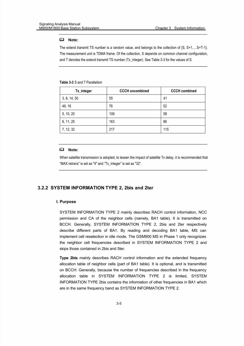
7/30/2019 Signaling Analysis Manual
http://slidepdf.com/reader/full/signaling-analysis-manual 78/290
Signaling Analysis ManualM900/M1800 Base Station Subsystem Chapter 3 System Information
3-5
Note:
The extend transmit TS number is a random value, and belongs to the collection of {S, S+1,....S+T-1}.
The measurement unit is TDMA frame. Of the collection, S depends on common channel configuration,
and T denotes the extend transmit TS number (Tx_integer). See Table 3-3 for the values of S.
Table 3-3 S and T Parallelism
Tx_integer CCCH uncombined CCCH combined
3, 8, 14, 50 55 41
49. 16 76 52
5, 10, 20 109 586, 11, 25 163 86
7, 12, 32 217 115
Note:
When satellite transmission is adopted, to lessen the impact of satellite Tx delay, it is recommended that
“MAX retrans” is set as "4" and “Tx_integer” is set as "32".
3.2.2 SYSTEM INFORMATION TYPE 2, 2bis and 2ter
I. Purpose
SYSTEM INFORMATION TYPE 2 mainly describes RACH control information, NCC
permission and CA of the neighbor cells (namely, BA1 table). It is transmitted on
BCCH. Generally, SYSTEM INFORMATION TYPE 2, 2bis and 2ter respectively
describe different parts of BA1. By reading and decoding BA1 table, MS canimplement cell reselection in idle mode. The GSM900 MS in Phase 1 only recognizes
the neighbor cell frequencies described in SYSTEM INFORMATION TYPE 2 and
skips those contained in 2bis and 5ter.
Type 2bis mainly describes RACH control information and the extended frequency
allocation table of neighbor cells (part of BA1 table). It is optional, and is transmitted
on BCCH. Generally, because the number of frequencies described in the frequency
allocation table in SYSTEM INFORMATION TYPE 2 is limited, SYSTEM
INFORMATION TYPE 2bis contains the information of other frequencies in BA1 which
are in the same frequency band as SYSTEM INFORMATION TYPE 2.
7/30/2019 Signaling Analysis Manual
http://slidepdf.com/reader/full/signaling-analysis-manual 79/290
Signaling Analysis ManualM900/M1800 Base Station Subsystem Chapter 3 System Information
3-6
Type 2ter mainly describes the extended frequency allocation table of neighbor cells
(part of BA1 table). It is transmitted on BCCH. Only the multi-band MS can read this
information. The single-band GSM 900 or GSM 1800 MS will skip this information.
Because the frequencies contained in this information are in a frequency band whichis different from that of the current cell, such information is not needed by the
single-band MS.
II. Information content
SYS INFO 2 - - Neighbor Cell Desc.
- - NCC permitted
- - RACH Control Para.
SYS INFO 2 BIS - - Neighbor Cell Desc.
- - RACH Control Para.
SYS INFO 2TER - - Neighbor Cell Desc.
1) BA1
BA1 (neighbor cell description) mainly describes the absolute frequency No. of the
BCCH TRX of the neighbor cell. Currently, the maximum number of neighbor cells
supported by Huawei is 32. Except the 5th bit (BA-IND) and 6th bit (EXT-IND) of the
second byte in BA1, the coding mode of other information is the same as that of the
cell channel description table (Refer to subsection 1) of 3.2.1 II).
EXT_IND (Extension Indication) is transmitted in SYSTEM INFORMATION TYPE 2
and 5, indicating whether there are other extended neighbor cell frequencies to be
transmitted in SYSTEM INFORMATION TYPE 2bis and 5bis. It is a 1-bit code. "0"
indicates that SYSTEM INFORMATION TYPE 2 and 5 already contain the complete
BA table, and "1" indicates that type 2 and type 5 only contain part of BA table.
BA Indication (BA_IND) is transmitted in SYSTEM INFORMATION TYPE 2 and 5. It
is a 1-bit code, and is used by MS to select the data in BA1 and BA 2 before or after
modification. In other words, if the neighbor cell relation of the current cell and theBA2 table is changed during a session, BA_IND in SYSTEM INFORMATION TYPE 5
will be 1 instead of 0. This indicates that MS should perform decoding for the
neighbor cell frequencies indicated in the SYSTEM INFORMATION TYPE 5 again.
2) NCC Permitted
NCC Permitted is transmitted in SYSTEM INFORMATION TYPE 2 and type 5. It is
an 8-bit code, and contains the collection of the NCCs to be measured by MS. In
other words, if 0≤N≤7 (N denotes the number of bits), MS will not measure the cell
level that satisfies "NCC=N", i.e. MS will not be handed over to the network that
satisfies "NCC=N". This parameter is mostly used in handover.
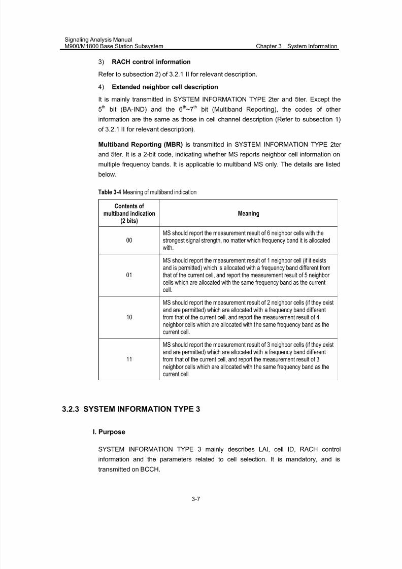
7/30/2019 Signaling Analysis Manual
http://slidepdf.com/reader/full/signaling-analysis-manual 80/290
Signaling Analysis ManualM900/M1800 Base Station Subsystem Chapter 3 System Information
3-7
3) RACH control information
Refer to subsection 2) of 3.2.1 II for relevant description.
4) Extended neighbor cell description
It is mainly transmitted in SYSTEM INFORMATION TYPE 2ter and 5ter. Except the
5th
bit (BA-IND) and the 6th~7
thbit (Multiband Reporting), the codes of other
information are the same as those in cell channel description (Refer to subsection 1)
of 3.2.1 II for relevant description).
Multiband Reporting (MBR) is transmitted in SYSTEM INFORMATION TYPE 2ter
and 5ter. It is a 2-bit code, indicating whether MS reports neighbor cell information on
multiple frequency bands. It is applicable to multiband MS only. The details are listed
below.
Table 3-4 Meaning of multiband indication
Contents of multiband indication
(2 bits)Meaning
00MS should report the measurement result of 6 neighbor cells with thestrongest signal strength, no matter which frequency band it is allocatedwith.
01
MS should report the measurement result of 1 neighbor cell (if it existsand is permitted) which is allocated with a frequency band different fromthat of the current cell, and report the measurement result of 5 neighbor
cells which are allocated with the same frequency band as the currentcell.
10
MS should report the measurement result of 2 neighbor cells (if they existand are permitted) which are allocated with a frequency band differentfrom that of the current cell, and report the measurement result of 4neighbor cells which are allocated with the same frequency band as thecurrent cell.
11
MS should report the measurement result of 3 neighbor cells (if they existand are permitted) which are allocated with a frequency band differentfrom that of the current cell, and report the measurement result of 3neighbor cells which are allocated with the same frequency band as thecurrent cell.
3.2.3 SYSTEM INFORMATION TYPE 3
I. Purpose
SYSTEM INFORMATION TYPE 3 mainly describes LAI, cell ID, RACH control
information and the parameters related to cell selection. It is mandatory, and is
transmitted on BCCH.
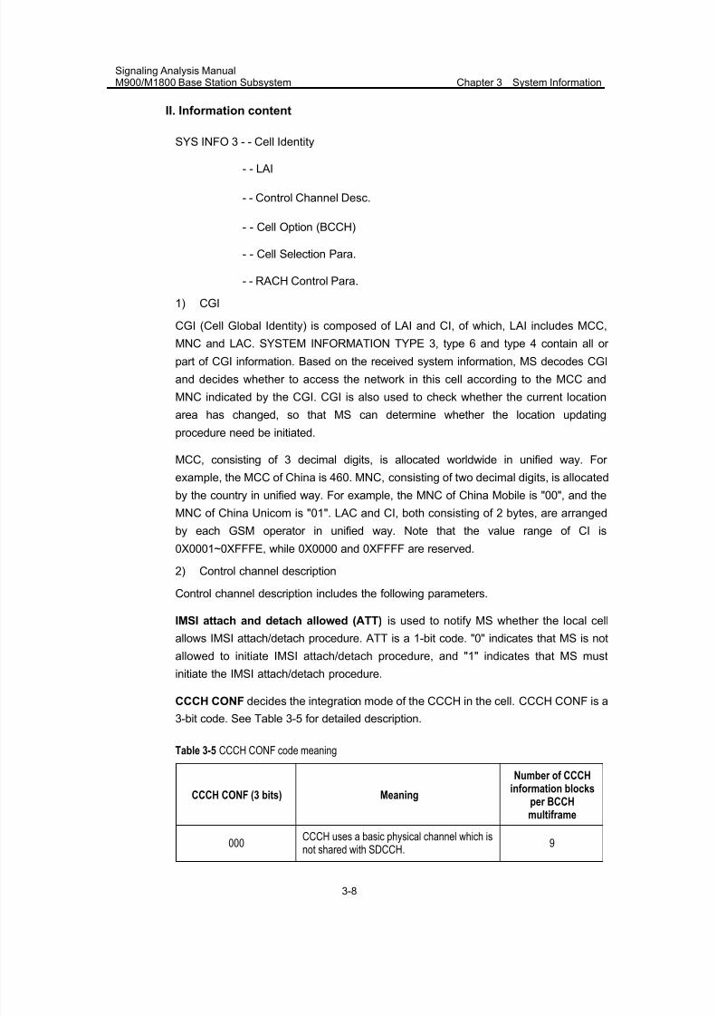
7/30/2019 Signaling Analysis Manual
http://slidepdf.com/reader/full/signaling-analysis-manual 81/290
Signaling Analysis ManualM900/M1800 Base Station Subsystem Chapter 3 System Information
3-8
II. Information content
SYS INFO 3 - - Cell Identity
- - LAI
- - Control Channel Desc.
- - Cell Option (BCCH)
- - Cell Selection Para.
- - RACH Control Para.
1) CGI
CGI (Cell Global Identity) is composed of LAI and CI, of which, LAI includes MCC,
MNC and LAC. SYSTEM INFORMATION TYPE 3, type 6 and type 4 contain all or
part of CGI information. Based on the received system information, MS decodes CGI
and decides whether to access the network in this cell according to the MCC and
MNC indicated by the CGI. CGI is also used to check whether the current location
area has changed, so that MS can determine whether the location updating
procedure need be initiated.
MCC, consisting of 3 decimal digits, is allocated worldwide in unified way. For
example, the MCC of China is 460. MNC, consisting of two decimal digits, is allocated
by the country in unified way. For example, the MNC of China Mobile is "00", and the
MNC of China Unicom is "01". LAC and CI, both consisting of 2 bytes, are arranged
by each GSM operator in unified way. Note that the value range of CI is
0X0001~0XFFFE, while 0X0000 and 0XFFFF are reserved.
2) Control channel description
Control channel description includes the following parameters.
IMSI attach and detach allowed (ATT) is used to notify MS whether the local cell
allows IMSI attach/detach procedure. ATT is a 1-bit code. "0" indicates that MS is not
allowed to initiate IMSI attach/detach procedure, and "1" indicates that MS must
initiate the IMSI attach/detach procedure.
CCCH CONF decides the integration mode of the CCCH in the cell. CCCH CONF is a
3-bit code. See Table 3-5 for detailed description.
Table 3-5 CCCH CONF code meaning
CCCH CONF (3 bits) Meaning
Number of CCCHinformation blocks
per BCCHmultiframe
000
CCCH uses a basic physical channel which is
not shared with SDCCH. 9
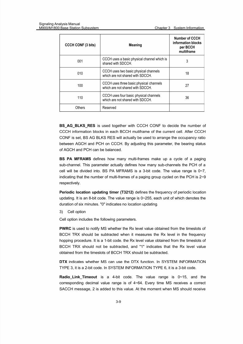
7/30/2019 Signaling Analysis Manual
http://slidepdf.com/reader/full/signaling-analysis-manual 82/290
Signaling Analysis ManualM900/M1800 Base Station Subsystem Chapter 3 System Information
3-9
CCCH CONF (3 bits) Meaning
Number of CCCHinformation blocks
per BCCHmultiframe
001CCCH uses a basic physical channel which isshared with SDCCH.
3
010CCCH uses two basic physical channelswhich are not shared with SDCCH.
18
100CCCH uses three basic physical channelswhich are not shared with SDCCH.
27
110CCCH uses four basic physical channelswhich are not shared with SDCCH.
36
Others Reserved
BS_AG_BLKS_RES is used together with CCCH CONF to decide the number of
CCCH information blocks in each BCCH mutiframe of the current cell. After CCCH
CONF is set, BS AG BLKS RES will actually be used to arrange the occupancy ratio
between AGCH and PCH on CCCH. By adjusting this parameter, the bearing status
of AGCH and PCH can be balanced.
BS PA MFRAMS defines how many multi-frames make up a cycle of a paging
sub-channel. This parameter actually defines how many sub-channels the PCH of a
cell will be divided into. BS PA MFRAMS is a 3-bit code. The value range is 0~7,indicating that the number of multi-frames of a paging group cycled on the PCH is 2~9
respectively.
Periodic location updating timer (T3212) defines the frequency of periodic location
updating. It is an 8-bit code. The value range is 0~255, each unit of which denotes the
duration of six minutes. "0" indicates no location updating.
3) Cell option
Cell option includes the following parameters.
PWRC is used to notify MS whether the Rx level value obtained from the timeslots of BCCH TRX should be subtracted when it measures the Rx level in the frequency
hopping procedure. It is a 1-bit code. the Rx level value obtained from the timeslots of
BCCH TRX should not be subtracted, and "1" indicates that the Rx level value
obtained from the timeslots of BCCH TRX should be subtracted.
DTX indicates whether MS can use the DTX function. In SYSTEM INFORMATION
TYPE 3, it is a 2-bit code. In SYSTEM INFORMATION TYPE 6, it is a 3-bit code.
Radio_Link_Timeout is a 4-bit code. The value range is 0~15, and the
corresponding decimal value range is of 4~64. Every time MS receives a correct
SACCH message, 2 is added to this value. At the moment when MS should receive
7/30/2019 Signaling Analysis Manual
http://slidepdf.com/reader/full/signaling-analysis-manual 83/290
Signaling Analysis ManualM900/M1800 Base Station Subsystem Chapter 3 System Information
3-10
an SAACH message, if it cannot correctly decode the SAACH message, 1 will be
subtracted from this value. If this value is 0, MS will report a radio link fault to BTS.
4) Cell selection parameters
Cell selection parameters have impact upon the behaviors of MS after it is powered
on. The major parameters are as follows.
Cell Reselection Hysteresis is used for cell reselection. MS cannot implement cell
reselection unless the level of the neighbor cell (Here, the neighbor cell and the
current cell do not belong to the same location area) minus the C2 of the current cell
is greater than the specified value of cell selection hysteresis. It is a 3-bit code. The
value range is 0~7, denoting 0dB ~14dB respectively.
MS_TXPWR_MAX_CCH indicates the Tx power used by MS before it receives a
power control command. It is a 5-bit code. The valid value range is 0~31, whichrespectively correspond to an MS output power.
RXLEV_ACCESS_MIN indicates the min. Rx level allowed for MS to access the
network. It is a 6-bit code. The value range is 0~63, denoting -110dBm~-47dBm
respectively.
ACS is used to notify MS whether to adopt C2 in the cell reselection procedure. It is a
1-bit code and is meaningless in SYSTEM INFORMATION TYPE 3. In SYSTEM
INFORMATION TYPE 4, if the value is 0, it indicates that MS adopts SI4 REST of
SYSTEM INFORMATION TYPE 4 to calculate C2-related parameters, or else, MS
adopts REST of SYSTEM INFORMATION TYPE 7 or type 8 to calculate c2-related
parameters.
NECI is used to notify MS whether the current cell supports half-rate services. It is a
1-bit code. "0" indicates that the current cell does not support half-rate services, and
"1" indicates the current cell supports half-rate services.
5) RACH control parameters
Refer to subsection 2) of 3.2.1 II for relevant description.
3.2.4 SYSTEM INFORMATION TYPE 4
I. Purpose
SYSTEM INFORMATION TYPE 4 mainly describes LAI, RACH control information,
cell selection parameters and optional CBCH information. It is mandatory, and is
transmitted on BCCH. When the system supports cell broadcast, the optional IE
CBCH description and MA will be used, and will describe CBCH configuration and the
corresponding frequency information
7/30/2019 Signaling Analysis Manual
http://slidepdf.com/reader/full/signaling-analysis-manual 84/290
Signaling Analysis ManualM900/M1800 Base Station Subsystem Chapter 3 System Information
3-11
II. Information content
SYS INFO 4 - - LAI
- - Cell Selection Para.
- - RACH Control Para.
- - CBCH Channel Desc.(optional)
- - CBCH Mobile Allocation (optional)
- SI4 Rest Oct.
1) LAI
Refer to subsection 1) of 3.2.3 2 II for relevant description.
2) Cell selection parameters
Refer to subsection 4) of 3.2.3 II for relevant description.
3) RACH control information
Refer to subsection 2) of 3.2.1 II for relevant description.
4) CBCH description and CBCH MA
The two parameters are optional. When the system supports cell broadcast, CBCH
description contains the formation about CBCH configuration. When CBCH
description is in frequency hopping mode, CBCH MA is mandatory.
5) SI4 Rest Oct.
When ACS of the cell selection parameters is set as "No", the relevant parameters in
SI4 Rest Oct. will be used to calculate the value of the cell reselection parameter C2.
Cell reselection criteria:
z When PENALTY_TIME = 31,
C2=C1-CELL_RESELECT_OFFSET
z When PENALTY_TIME≠31,
C2=C1+CELL_RESELECT_OFFSET-TEMPORARY_OFFSET*H(P
ENALTY_TIME-T)
Where,
For the non-serving cell: When x<0, H(x)=0; when x>=0, H(x)=1
For the serving cell, H(x)=0
SI4 Rest Oct. contains the following parameters.
PI (Cell Reselection Parameter Indication) indicates whether MS adopts C2 as the
cell reselection parameter, and whether the parameters used for calculating C2 exist.
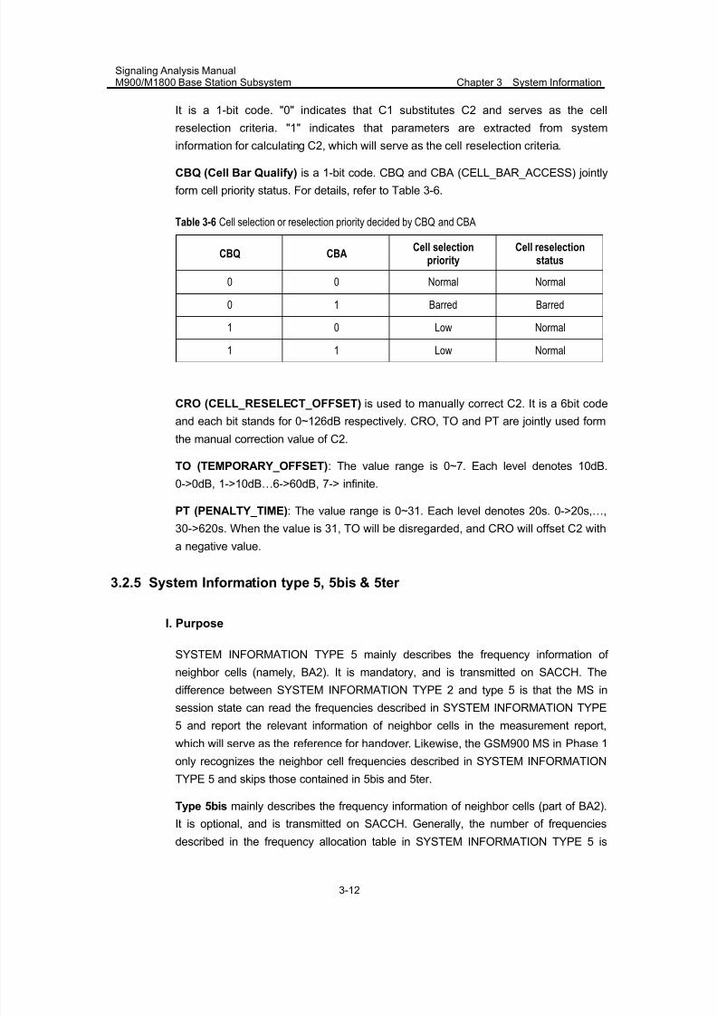
7/30/2019 Signaling Analysis Manual
http://slidepdf.com/reader/full/signaling-analysis-manual 85/290
Signaling Analysis ManualM900/M1800 Base Station Subsystem Chapter 3 System Information
3-12
It is a 1-bit code. "0" indicates that C1 substitutes C2 and serves as the cell
reselection criteria. "1" indicates that parameters are extracted from system
information for calculating C2, which will serve as the cell reselection criteria.
CBQ (Cell Bar Qualify) is a 1-bit code. CBQ and CBA (CELL_BAR_ACCESS) jointly
form cell priority status. For details, refer to Table 3-6.
Table 3-6 Cell selection or reselection priority decided by CBQ and CBA
CBQ CBACell selection
priorityCell reselection
status
0 0 Normal Normal
0 1 Barred Barred
1 0 Low Normal
1 1 Low Normal
CRO (CELL_RESELECT_OFFSET) is used to manually correct C2. It is a 6bit code
and each bit stands for 0~126dB respectively. CRO, TO and PT are jointly used form
the manual correction value of C2.
TO (TEMPORARY_OFFSET): The value range is 0~7. Each level denotes 10dB.
0->0dB, 1->10dB…6->60dB, 7-> infinite.
PT (PENALTY_TIME): The value range is 0~31. Each level denotes 20s. 0->20s,…,
30->620s. When the value is 31, TO will be disregarded, and CRO will offset C2 with
a negative value.
3.2.5 System Information type 5, 5bis & 5ter
I. Purpose
SYSTEM INFORMATION TYPE 5 mainly describes the frequency information of
neighbor cells (namely, BA2). It is mandatory, and is transmitted on SACCH. Thedifference between SYSTEM INFORMATION TYPE 2 and type 5 is that the MS in
session state can read the frequencies described in SYSTEM INFORMATION TYPE
5 and report the relevant information of neighbor cells in the measurement report,
which will serve as the reference for handover. Likewise, the GSM900 MS in Phase 1
only recognizes the neighbor cell frequencies described in SYSTEM INFORMATION
TYPE 5 and skips those contained in 5bis and 5ter.
Type 5bis mainly describes the frequency information of neighbor cells (part of BA2).
It is optional, and is transmitted on SACCH. Generally, the number of frequencies
described in the frequency allocation table in SYSTEM INFORMATION TYPE 5 is
7/30/2019 Signaling Analysis Manual
http://slidepdf.com/reader/full/signaling-analysis-manual 86/290
Signaling Analysis ManualM900/M1800 Base Station Subsystem Chapter 3 System Information
3-13
limited. Therefore, system information 5bis contains the information of other
frequencies in BA2 which are in the same frequency band as system information 5.
Type 5ter mainly describes the frequency information of neighbor cells (part of BA2),
and is transmitted on SACCH. Likewise, only the multiband MS can read this
information. The single-band GSM 900 or GSM 1800 MS will skip this information.
II. Information content
SYS INFO 5- - Neighbor Cell Desc.
SYS INFO 5 BIS - - Neighbor Cell Desc.
SYS INFO 5TER - - Neighbor Cell Desc.
1) Neighbor cell description
For relevant description, please Refer to subsection 1) of 3.2.2 II
2) Extended neighbor cell description
For relevant description, please Refer to subsection 4) of 3.2.2 II
3.2.6 SYSTEM INFORMATION TYPE 6
I. Purpose
SYSTEM INFORMATION TYPE 6 mainly describes LAI, cell ID and the parametersused for describing cell functions. It is mandatory, and is transmitted on SACCH.
II. Information content
SYS INFO 6 - - Cell Identity
- - LAI
- - Cell Option (SACCH)
- NCC Permitted
1) CGI
Refer to subsection 1) of 3.2.3 II
2) Cell option
Refer to subsection 3) of 3.2.3 II
3) NCC permitted
Refer to subsection 2) of 3.2.2 II
7/30/2019 Signaling Analysis Manual
http://slidepdf.com/reader/full/signaling-analysis-manual 87/290
Signaling Analysis ManualM900/M1800 Base Station Subsystem Chapter 3 System Information
3-14
3.2.7 SYSTEM INFORMATION TYPE 7
I. Purpose
SYSTEM INFORMATION TYPE 7 is mandatory, and is transmitted on BCCH. It
contains cell reselection information.
II. Information content
SYS INFO 7---- SI 7 Rest Octets
SI 7 Rest Octets contains the parameters used by MS for cell reselection. It can also
contain the information of the parameter POWER OFFSET used by DCS1800 Class 3
MS.
The coding format of SI 7 Rest Octets is the same with SI 4 Rest Octets. See the
related description in "5) SI 4 Rest Oct" of 3.2.4.
3.2.8 SYSTEM INFORMATION TYPE 8
I. Purpose
This system information is mandatory, and is transmitted on BCCH. It contains cell
reselection information.
II. Information content
SYS INFO 8 ---- SI 8 Rest Octets
SI 8 Rest Octets contains the parameters used by MS for cell reselection. It can also
contain the information of the parameter POWER OFFSET used by DCS1800 Class 3
MS.
The coding format of SI 8 Rest Octets is the same with SI 4 Rest Octets. See the
related description in "5) SI 4 Rest Oct" of 3.2.4.
3.3 Internal Handling of BSC
The internal handling of the BSC is given below:
1) The BSC retrieves cell frequencies in SYSTEM INFORMATION TYPE 1 from the
[Cell Allocation Table].
Table 3-7 shows the correspondence between the RACH control parameters in
SYSTEM INFORMATION TYPE 1 and the [System information table].
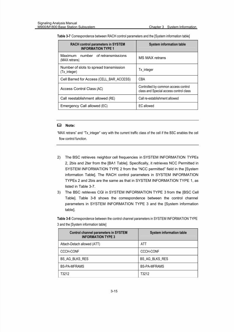
7/30/2019 Signaling Analysis Manual
http://slidepdf.com/reader/full/signaling-analysis-manual 88/290
Signaling Analysis ManualM900/M1800 Base Station Subsystem Chapter 3 System Information
3-15
Table 3-7 Correspondence between RACH control parameters and the [System information table]
RACH control parameters in SYSTEMINFORMATION TYPE 1
System information table
Maximum number of retransmissions (MAX retrans)
MS MAX retrans
Number of slots to spread transmission (Tx_integer)
Tx_integer
Cell Barred for Access (CELL_BAR_ACCESS) CBA
Access Control Class (AC)Controlled by common access controlclass and Special access control class
Call reestablishment allowed (RE) Call re-establishment allowed
Emergency Call allowed (EC) EC allowed
Note:
“MAX retrans” and “Tx_integer” vary with the current traffic class of the cell if the BSC enables the cell
flow control function.
2) The BSC retrieves neighbor cell frequencies in SYSTEM INFORMATION TYPEs
2, 2bis and 2ter from the [BA1 Table]. Specifically, it retrieves NCC Permitted in
SYSTEM INFORMATION TYPE 2 from the “NCC permitted” field in the [System
information Table]. The RACH control parameters in SYSTEM INFORMATION
TYPEs 2 and 2bis are the same as that in SYSTEM INFORMATION TYPE 1, as
listed in Table 3-7.
3) The BSC retrieves CGI in SYSTEM INFORMATION TYPE 3 from the [BSC Cell
Table]. Table 3-8 shows the correspondence between the control channel
parameters in SYSTEM INFORMATION TYPE 3 and the [System information
table].
Table 3-8 Correspondence between the control channel parameters in SYSTEM INFORMATION TYPE
3 and the [System information table]
Control channel parameters in SYSTEMINFORMATION TYPE 3
System information table
Attach-Detach allowed (ATT) ATT
CCCH-CONF CCCH-CONF
BS_AG_BLKS_RES BS_AG_BLKS_RES
BS-PA-MFRAMS BS-PA-MFRAMS
T3212 T3212
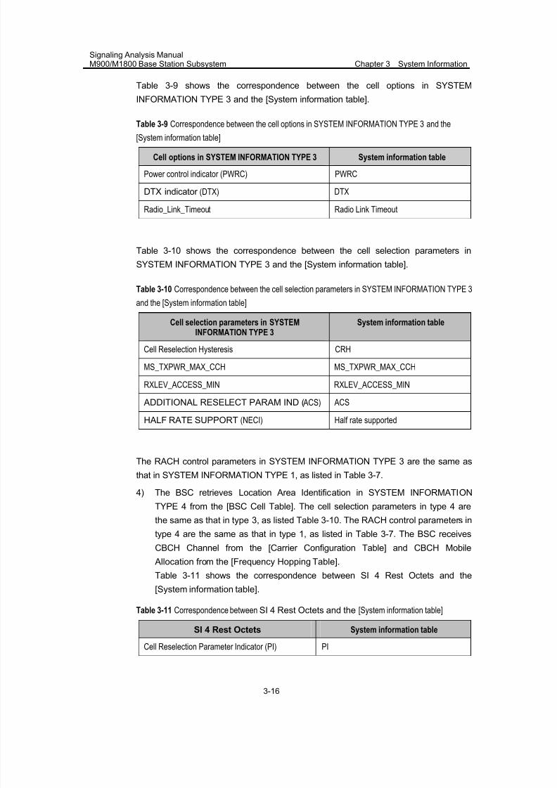
7/30/2019 Signaling Analysis Manual
http://slidepdf.com/reader/full/signaling-analysis-manual 89/290
Signaling Analysis ManualM900/M1800 Base Station Subsystem Chapter 3 System Information
3-16
Table 3-9 shows the correspondence between the cell options in SYSTEM
INFORMATION TYPE 3 and the [System information table].
Table 3-9 Correspondence between the cell options in SYSTEM INFORMATION TYPE 3 and the
[System information table]
Cell options in SYSTEM INFORMATION TYPE 3 System information table
Power control indicator (PWRC) PWRC
DTX indicator (DTX) DTX
Radio_Link_Timeout Radio Link Timeout
Table 3-10 shows the correspondence between the cell selection parameters in
SYSTEM INFORMATION TYPE 3 and the [System information table].
Table 3-10 Correspondence between the cell selection parameters in SYSTEM INFORMATION TYPE 3
and the [System information table]
Cell selection parameters in SYSTEMINFORMATION TYPE 3
System information table
Cell Reselection Hysteresis CRH
MS_TXPWR_MAX_CCH MS_TXPWR_MAX_CCH
RXLEV_ACCESS_MIN RXLEV_ACCESS_MIN
ADDITIONAL RESELECT PARAM IND ( ACS) ACS
HALF RATE SUPPORT (NECI) Half rate supported
The RACH control parameters in SYSTEM INFORMATION TYPE 3 are the same as
that in SYSTEM INFORMATION TYPE 1, as listed in Table 3-7.
4) The BSC retrieves Location Area Identification in SYSTEM INFORMATION
TYPE 4 from the [BSC Cell Table]. The cell selection parameters in type 4 are
the same as that in type 3, as listed Table 3-10. The RACH control parameters in
type 4 are the same as that in type 1, as listed in Table 3-7. The BSC receives
CBCH Channel from the [Carrier Configuration Table] and CBCH Mobile
Allocation from the [Frequency Hopping Table].
Table 3-11 shows the correspondence between SI 4 Rest Octets and the
[System information table].
Table 3-11 Correspondence between SI 4 Rest Octets and the [System information table]
SI 4 Rest Octets System information table
Cell Reselection Parameter Indicator (PI) PI
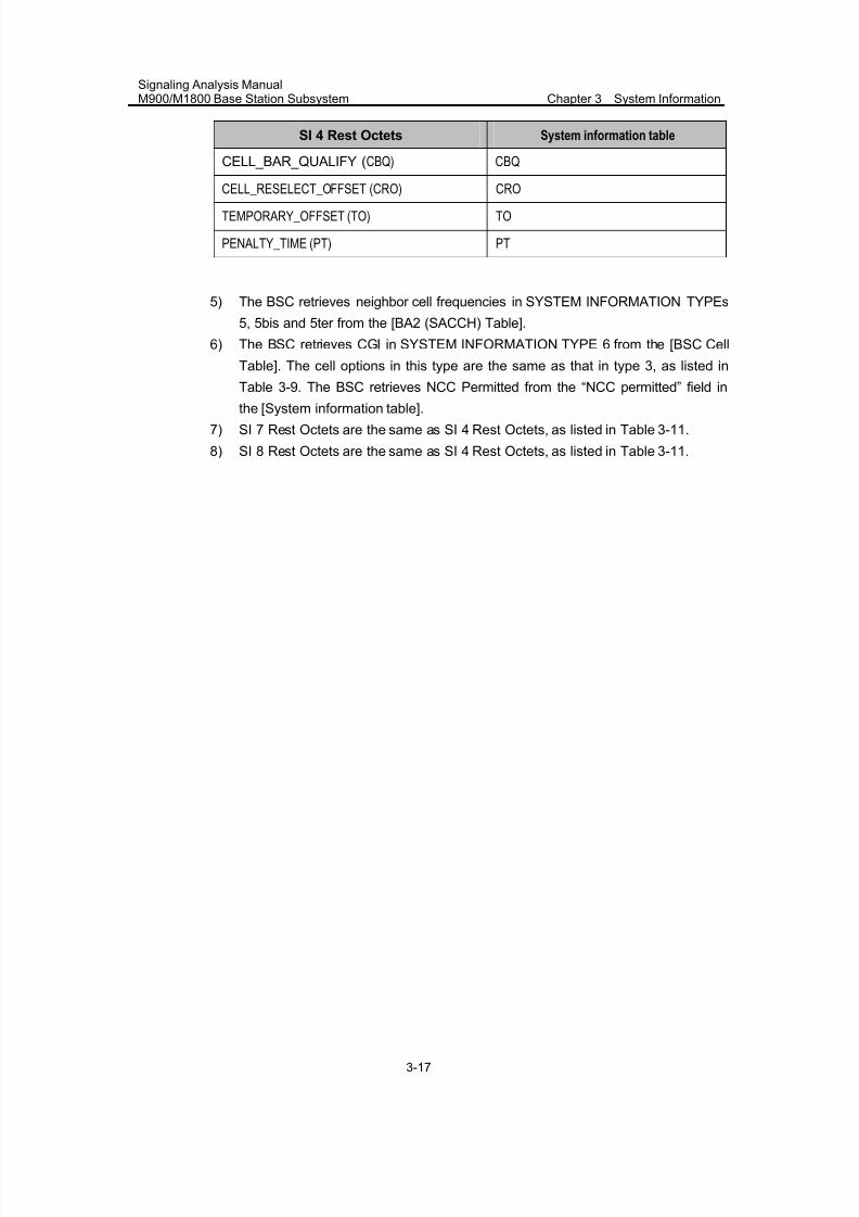
7/30/2019 Signaling Analysis Manual
http://slidepdf.com/reader/full/signaling-analysis-manual 90/290
Signaling Analysis ManualM900/M1800 Base Station Subsystem Chapter 3 System Information
3-17
SI 4 Rest Octets System information table
CELL_BAR_QUALIFY (CBQ) CBQ
CELL_RESELECT_OFFSET (CRO) CRO
TEMPORARY_OFFSET (TO) TO
PENALTY_TIME (PT) PT
5) The BSC retrieves neighbor cell frequencies in SYSTEM INFORMATION TYPEs
5, 5bis and 5ter from the [BA2 (SACCH) Table].
6) The BSC retrieves CGI in SYSTEM INFORMATION TYPE 6 from the [BSC Cell
Table]. The cell options in this type are the same as that in type 3, as listed in
Table 3-9. The BSC retrieves NCC Permitted from the “NCC permitted” field in
the [System information table].
7) SI 7 Rest Octets are the same as SI 4 Rest Octets, as listed in Table 3-11.
8) SI 8 Rest Octets are the same as SI 4 Rest Octets, as listed in Table 3-11.
7/30/2019 Signaling Analysis Manual
http://slidepdf.com/reader/full/signaling-analysis-manual 91/290
Signaling Analysis ManualM900/M1800 Base Station Subsystem Chapter 4 Location Update Procedure
4-1
Chapter 4 Location Update Procedure
4.1 Overview
In GSM system, MS location information need be known by HLR, VLR and MS, When
the location information changes, it is required that the relevant information in HLR,
VLR and MS should be consistent, which can be realized through the location
updating procedure. As the major procedure of location management, the location
updating procedure is always initiated on MS side.
The location updating procedure is a general procedure, and is used for 3 purposes,
i.e. normal location updating, periodic updating and IMSI attach.
The normal location updating procedure is used to update the registration of the
actual location area of MS in the network. The location updating type information
element in the LOCATION UPDATING REQUEST message shall indicate normal
location updating.
When the network indicates that MS is unknown in VLR, the normal location updating
procedure will be started, as a response to the MM connection establishment request.
In case that location updating is unsuccessful, to limit the number of location updating
attempts, an attempt counter need be used. The attempt counter is reset when MS is
switched on or a SIM card is inserted.
MS contains a list of "forbidden location areas for roaming", as well as a list of
"forbidden location areas for regional provision of service". These lists shall be erased
when an MS is switched off or when SIM is removed. Whenever a LOCATION
UPDATING REJECT message is received with the cause "Roaming not allowed in
this location area" or with the cause "Location area not allowed", the LAI received on
BCCH that triggered the location updating request shall be added to the relevant list.
The two lists shall accommodate 10 or more entries. When the list is full and a new
entry has to be inserted, the oldest entry shall be deleted.
Upon successful location updating, MS sets the update status to "UPDATED" in SIM
(UPDATED status indicates the last location updating request is successful) , and
save LAI, TMSI, Cipher Key and Cipher Sequence Number in SIM, and stores the
received new location area information in SIM.
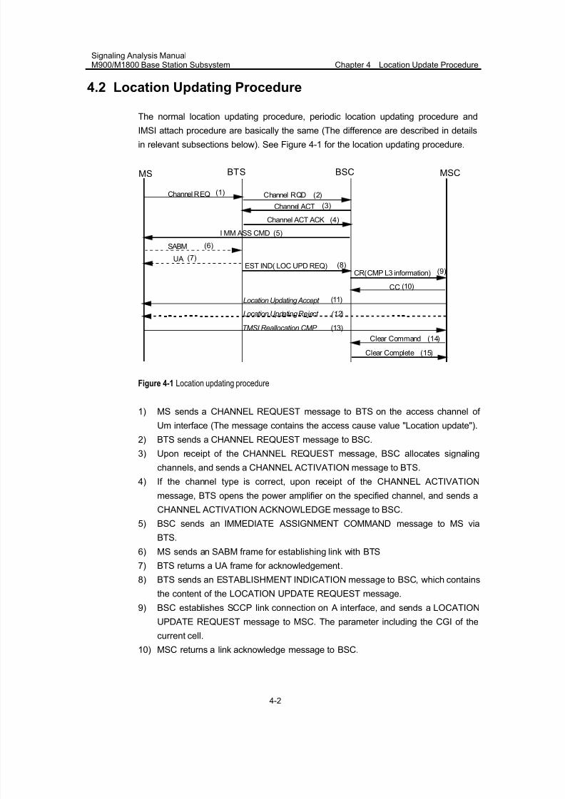
7/30/2019 Signaling Analysis Manual
http://slidepdf.com/reader/full/signaling-analysis-manual 92/290
Signaling Analysis ManualM900/M1800 Base Station Subsystem Chapter 4 Location Update Procedure
4-2
4.2 Location Updating Procedure
The normal location updating procedure, periodic location updating procedure and
IMSI attach procedure are basically the same (The difference are described in detailsin relevant subsections below). See Figure 4-1 for the location updating procedure.
BTS BSC MSCMS
Channel ACT
Channel ACT ACK
I MM ASS CMD
Channel REQ
CC
TMSI Reallocation CMP
Location Updating Accept
(1)
(3)
(4)
(5)
SABM
EST IND( LOC UPD REQ) CR(CMP L3 information)
UA
(6)
(7)
(8) (9)
(10)
(11)
(13)
Channel RQD (2)
Clear Command (14)
Clear Complete (15)
Location U pdating Reject (12)
Figure 4-1 Location updating procedure
1) MS sends a CHANNEL REQUEST message to BTS on the access channel of
Um interface (The message contains the access cause value "Location update").
2) BTS sends a CHANNEL REQUEST message to BSC.
3) Upon receipt of the CHANNEL REQUEST message, BSC allocates signaling
channels, and sends a CHANNEL ACTIVATION message to BTS.
4) If the channel type is correct, upon receipt of the CHANNEL ACTIVATION
message, BTS opens the power amplifier on the specified channel, and sends a
CHANNEL ACTIVATION ACKNOWLEDGE message to BSC.
5) BSC sends an IMMEDIATE ASSIGNMENT COMMAND message to MS via
BTS.
6) MS sends an SABM frame for establishing link with BTS
7) BTS returns a UA frame for acknowledgement.
8) BTS sends an ESTABLISHMENT INDICATION message to BSC, which contains
the content of the LOCATION UPDATE REQUEST message.
9) BSC establishes SCCP link connection on A interface, and sends a LOCATION
UPDATE REQUEST message to MSC. The parameter including the CGI of the
current cell.
10) MSC returns a link acknowledge message to BSC.
7/30/2019 Signaling Analysis Manual
http://slidepdf.com/reader/full/signaling-analysis-manual 93/290
Signaling Analysis ManualM900/M1800 Base Station Subsystem Chapter 4 Location Update Procedure
4-3
11) MSC sends a LOCATION UPDATING ACCEPT message to BSC, indicating that
location updating has succeeded.
12) The network shall deliver a LOCATION UPDATING REJECT message to MS if it
rejects the location updating request.13) If "Allocate TMSI upon location updating" is set to "No" in MSC, MS shall not
report the TMSI REALLOCATION COMPLETE message in the location updating
procedure.
14) The network shall initiate the channel release procedure if no further transactions
are scheduled.
4.2.1 Periodic Updating
Periodic updating is used to notify periodically the availability of MS to the network. It
is performed by using the location updating procedure. The location updating typeinformation element in the LOCATION UPDATING REQUEST message shall indicate
periodic updating.
The procedure is controlled by timer T3212 in MS. If the timer has not been started,
the timer shall be started each time MS enters the "NORMAL SERVICE" or
"ATTEMPTING TO UPDATE" sub-state of the "MM IDLE" state. When MS leaves the
"MM Idle" state (MM IDLE state indicates MS in inactivation state, namely, it doesn't
process any call procedure, only in interception state. For example, in MOC or MOT
procedure, MS will leave MM_IDLE state), timer T3212 shall continue running until it
is overtime.
In the following cases, the timer shall be stopped (MS shall set the timer to its initial
value for the next location update).
z A LOCATION UPDATING ACCEPT or LOCATION UPDATING REJECT
message is received.
z An AUTHENTICATION REJECT message is received.
z The first MM message (Such as LOCATION ACCEPT, CM SERVICE ACCEPT
etc.) is received, or ciphering mode setting is completed in the case of MM
connection establishment, except when the most recent service state is
"LIMITED SERVICE".
z MS has responded to paging and thereafter has received the first correct layer 3
message except RR message.
z Timer T3212 expires.
z MS is deactivated (i.e. MS switched off or SIM removed).
When timer T3212 expires, the location updating procedure shall be started.
When MS is in the service state of "NO CELL AVAILABLE", "LIMITED SERVICE",
"PLMN SEARCH" or "PLMN SEARCH-NORMAL SERVICE", if the T3212 timer
expires, the location updating procedure shall be delayed until the MS leaves this
service state. The (periodic) location updating procedure is not be started if the
7/30/2019 Signaling Analysis Manual
http://slidepdf.com/reader/full/signaling-analysis-manual 94/290
Signaling Analysis ManualM900/M1800 Base Station Subsystem Chapter 4 Location Update Procedure
4-4
system information at the time the T3212 timer expires indicates that periodic location
update shall not be used. The timeout value is contained in control channel
description IE of the SYSTEM INFORMATION TYPE 3 message.
The T3212 timeout value shall not be changed when MS is in the state of "NO CELL
AVAILABLE", "LIMITED SERVICE", "PLMN SEARCH or PLMN SEARCH-NORMAL"
etc.
When a change of the T3212 timeout value has to be taken into account and the
timer is running (at change of the serving cell or, the broadcast of T3212 timeout
value), MS shall take the mod that the current T3212 value to the new T3212 timeout
value as the new initial value.
When MS is activated, or when a change of the T3212 timeout value has to be taken
into account and the timer is not running, the new timer shall be started at a valuerandomly, uniformly drawn between 1 and the new initial value.
4.2.2 IMSI Attach Procedure
The IMSI attach procedure is the complement of the IMSI detach procedure. It is used
to indicate the IMSI as active in the network. There is a flag (ATT) in the SYSTEM
INFORMATION TYPE 3 message, which indicates whether the attach and detach
procedures are required to be used or not.
The IMSI attach procedure is invoked when the IMSI is activated by MS, if thedetach/attach procedures are required by the network.
When IMSI is activated by MS within the network coverage area, or if MS is moved
from outside the coverage area to the coverage area. The IMSI attach procedure is
used only if the update status is "UPDATED" and if the stored LAI is the same as the
one which is actually broadcasted on the BCCH of the current serving cell. Otherwise
a normal location updating procedure shall be invoked, which is independent of the
ATT flag indication.
IMSI attach is performed by using the location updating procedure. The location
updating type information element in the LOCATION UPDATING REQUEST message
must in this case indicate IMSI attach.
4.2.3 Generic Location Updating Procedure
Any timer used for triggering the location updating procedure (e.g. T3211 and T3212)
is stopped if running.
As no RR connection exists at the time when the location updating procedure has to
be started, the MM sublayer within MS will request the RR sublayer to establish a RR
7/30/2019 Signaling Analysis Manual
http://slidepdf.com/reader/full/signaling-analysis-manual 95/290
Signaling Analysis ManualM900/M1800 Base Station Subsystem Chapter 4 Location Update Procedure
4-5
connection and enter the state of "WAIT FOR RR CONNECTION (LOCATION
UPDATE)".
MS initiates the location updating procedure by sending a LOCATION UPDATING
REQUEST message to the network, starts the timer T3210 and enters the state of
"LOCATION UPDATING INITIATED". The location updating type information element
shall indicate what kind of updating is requested.
I. Network requests for additional MS capability information
The network may initiate the classmark interrogation procedure, for example, to
obtain further information on MS's encryption capabilities.
II. Identification request
The network may initiate the identification procedure, e.g. if the network is unable to
get the IMSI based on the TMSI and LAI used as identification by MS
III. Authentication procedure
The authentication procedure may be initiated by the network upon receipt of the
LOCATION UPDATING REQUEST message from MS.
IV. Ciphering mode setting procedure
The ciphering mode setting procedure may be initiated by the network, if a new TMSI
has to be allocated.
V. Attempt counter
When location updating is unsuccessful, to limit the number of location updating
attempts, an attempt counter is used. It counts the number of consecutive
unsuccessful location update attempts.
The attempt counter is incremented by 1 each time a location update procedure fails.
In the following cases, the attempt counter shall be reset.
z MS is powered on
z A SIM card is inserted
z Location update is successfully completed
z Location update is completed with cause 11/12/13
z Service state changes from "ATTEMPTING" into "UPDATE"
z A new location area is entered
z Timer T3212 expires
z Location update is triggered by a CM sublayer request
7/30/2019 Signaling Analysis Manual
http://slidepdf.com/reader/full/signaling-analysis-manual 96/290
Signaling Analysis ManualM900/M1800 Base Station Subsystem Chapter 4 Location Update Procedure
4-6
The attempt counter is used when MS decides whether to re-attempt a location
update after timeout of timer T3211.
VI. Location updating accepted
If the location updating is accepted by the network, a LOCATION UPDATING
ACCEPT message shall be transferred to MS.
In case the identity confidentiality service is active, the TMSI reallocation may be part
of the location updating procedure. The TMSI allocated is then contained in the
LOCATION UPDATING ACCEPT message together with LAI. The network shall in
this case start the supervision timer T3250.
Upon receipt of a LOCATION UPDATING ACCEPT message, MS stores the received
LAI, stops timer T3210, resets the attempt counter and sets the update status in SIMto "UPDATED". If the message contains an IMSI, MS is not allocated any TMSI, and
shall delete any TMSI from SIM accordingly. If the message contains a TMSI, the MS
is allocated this TMSI, and shall store this TMSI in SIM and send a TMSI
REALLOCATION COMPLETE to the network. If neither IMSI nor TMSI is received in
the LOCATION UPDATING ACCEPT message, the old TMSI if any available shall be
kept.
If the LAI or PLMN identity contained in the LOCATION UPDATING ACCEPT
message is a member of any of the "forbidden lists", the relevant entries shall be
deleted.
VII. Location updating rejected
If the location updating cannot be accepted, the network sends a LOCATION
UPDATING REJECT message to the MS. After receipt of the LOCATION UPDATING
REJECT message, MS shall stop timer T3210, store the reject cause, start T3240,
enter the state of "LOCATION UPDATING REJECTED" and await the release of the
RR connection triggered by the network. Upon the release of the RR connection, MS
shall take the following actions depending on the stored reject cause.
z Cause 2: IMSI unknown in HLRz Cause 3: illegal MS
z Cause 6: illegal ME
For cause 2/3/6, the MS shall set the update status to "ROAMING NOT ALLOWED",
and delete any TMSI, stored LAI and ciphering key sequence number and shall
consider IMSI invalid until switch-off.
z Cause 11: PLMN not allowed
z Cause 12: location area not allowed
z Cause 13: roaming not allowed in this location area
7/30/2019 Signaling Analysis Manual
http://slidepdf.com/reader/full/signaling-analysis-manual 97/290
Signaling Analysis ManualM900/M1800 Base Station Subsystem Chapter 4 Location Update Procedure
4-7
For cause 11/12/13, MS shall delete any LAI, TMSI and ciphering key sequence
number stored in from SIM, reset the attempt counter, and set the update status to
"ROAMING NOT ALLOWED". MS shall store the LAI or the PLMN identity in the
relevant forbidden list, i.e. in the "forbidden PLMN list" for cause 11, in the list of "forbidden location areas for regional provision of service" for cause 12, and in the list
of "forbidden location areas for roaming" for cause 13. In addition, MS will memorize if
cause 13 is received, so to perform PLMN selection instead of cell selection when it is
back to the "MM IDLE" state.
Other cause values are considered as abnormal cases.
VIII. Release of RR connection after location updating
When the location updating procedure is completed, MS shall (except in the case that
MS has a follow-on CM application request pending and has received the follow-on
proceed indication) set timer T3240 and enter the state of "WAIT FOR NETWORK
COMMAND", expecting the release of RR connection. The network may decide to
keep the RR connection for network-initiated establishment of a new MM connection,
or to allow for MS-initiated MM connection establishment.
Any release of RR connection shall be initiated by the network. If the RR connection
is not released within a given time controlled by timer T3240, MS shall abort the RR
connection. In both cases, either after a RR connection release triggered from the
network side or after a RR connection abort requested by MS side, MS shall return to
the state of "MM IDLE".
At transition to the state "MM IDLE", sub-state "NORMAL SERVICE" or
"ATTEMPTING TO UPDATE", either timer T3212 or timer T3211 is started.
IX. Abnormal cases on MS side
There are the following abnormal cases on MS side.
1) Access barred because of access class control
MS stays in the current serving cell and initiates the normal cell reselection procedure.
The procedure is started as soon as the access is allowed.
2) The answer to random access is an IMMEDIATE ASSIGNMENT REJECT
message
MS stays in the chosen cell and applies the normal cell selection procedure. Timer
T3122 is reset when a cell change occurs. The procedure is started as soon as timer
T3122 expires.
3) Random access failure
7/30/2019 Signaling Analysis Manual
http://slidepdf.com/reader/full/signaling-analysis-manual 98/290
Signaling Analysis ManualM900/M1800 Base Station Subsystem Chapter 4 Location Update Procedure
4-8
If random access failure occur, Timer T3213 is started. When it expires, the random
access procedure is attempted again. The location updating procedure is aborted if
random access fails twice successively.
4) RR connection failure
The procedure is aborted.
5) T3210 timeout
The procedure is aborted, and the RR connection is terminated.
6) RR released before the normal end of procedure
The procedure is aborted.
7) Location updating rejected, due to cause except 2/3/6/11/12/13
MS waits for release of the RR connection. In cases 4~7 and for repeated failures as
defined in case 3, MS proceeds as follows. Timer T3210 is stopped if still running.
The RR connection is released if timer T3210 expires. The attempt counter is
incremented by 1. The next actions depend on LAI and the value of the attempt
counter.
Case 1: The update status is "UPDATED", and the stored LAI is equal to the one
received on the BCCH from the current serving cell. The attempt counter is smaller
than 4.
In case 1, MS shall keep the update status to "UPDATED". The MM IDLE sub-state
after RR connection release is "NORMAL SERVICE". MS shall memorize the locationupdating type used in the location updating procedure. It shall start timer T3211 when
the RR connection is released. When timer T3211 expires, the location updating
procedure is triggered again with the memorized location updating type.
Case 2: Either the update status is different from "UPDATED", or the stored LAI is
different from the one received on the BCCH from the current serving cell, or the
attempt counter is greater or equal to 4.
In case 2, MS shall delete any LAI, TMSI and ciphering key sequence number stored
in SIM, set the update status to "NOT UPDATED" and enter the MM IDLE sub-state
"ATTEMPTING TO UPDATE" when the RR connection is released. If the attempt
counter is smaller than 4, MS shall start timer T3211. Otherwise, it starts timer T3212.
X. Abnormal cases on network side
1) RR connection failure
If a RR connection failure occurs during a common procedure which is integrated with
the location updating procedure, the behavior of the network should be according to
the description of that common procedure.
7/30/2019 Signaling Analysis Manual
http://slidepdf.com/reader/full/signaling-analysis-manual 99/290
Signaling Analysis ManualM900/M1800 Base Station Subsystem Chapter 4 Location Update Procedure
4-9
If there is no other common procedure integrated, the location updating procedure
towards MS shall be aborted.
2) Protocol error
If the LOCATION UPDATING REQUEST message is received with a protocol error,
the network shall, if possible, return a LOCATION UPDATING REJECT message with
one of the following causes.
z Cause 96: Mandatory IE error
z Cause 99: IE non-existent or not implemented
z Cause 100: Conditional IE error
z Cause 111: Protocol error, unspecified
After sending the response message, the network will start the channel release
procedure.
4.3 Internal Handling of BSC
The location updating procedure is a general procedure for three purposes: normal
location updating, periodic updating and IMSI attach.
The BSC retrieves the periodic location updating period from the “T3212” field in the
[System information table] and sends it to the MS through the SYSTEM
INFORMATION TYPE 3 message.
The BSC sends a LOCATION UPDATING REQUEST message to the MSC to set upan SCCP connection over interface A. This message includes the CGI of the serving
cell. See [BSC Cell Table] for the CGI.
7/30/2019 Signaling Analysis Manual
http://slidepdf.com/reader/full/signaling-analysis-manual 100/290
Signaling Analysis ManualM900/M1800 Base Station Subsystem Chapter 5 Authentication Procedure
5-1
Chapter 5 Authentication Procedure
5.1 Overview
Authentication refers to the procedure of authenticating the validity of the IMSI and
TMSI of MS initiated by the GSM network.
The purpose of the authentication procedure is to prevent illegal MS from accessing
the network, and in the meantime, to protect the private information of legal MS from
leakage.
On the following conditions, the network may initiate the authentication procedure.
z MS requests modification of its relevant information in VLR or HLR.
z Service access is initiated (MS originates a call. MS is called. MS is
activated/deactivated. Supplementary service is initiated)
z MS accesses the network for the first time after MSC/VLR is restarted
z The ciphering key sequence number Kc is not matched.
The purpose of the authentication procedure is twofold.
z To permit the network to check whether the identity provided by MS is
acceptable or not
z To provide parameters enabling MS to calculate a new ciphering key
The authentication procedure is always initiated and controlled by the network.
5.2 Authentication Procedure
The network initiates the authentication procedure by transferring an
AUTHENTICATION REQUEST message to MS and starts timer T3260. The
AUTHENTICATION REQUEST message contains the parameters used to calculate
the response parameters, and also contains the CKSN (Ciphering Key SequenceNumber) allocated to the key which may be computed from the given parameters.
Upon receipt of the AUTHENTICATION REQUEST message, MS processes the
challenge information and sends back an AUTHENTICATION RESPONSE message
to the network. The new ciphering key Kc calculated from the challenge information
shall overwrite the previous one and be stored in SIM before the AUTHENTICATION
RESPONSE message is transmitted. The CKSN shall be stored together with the
calculated Kc.
Upon receipt of the AUTHENTICATION RESPONSE message, the network stops
timer T3260 and checks the validity of the response.
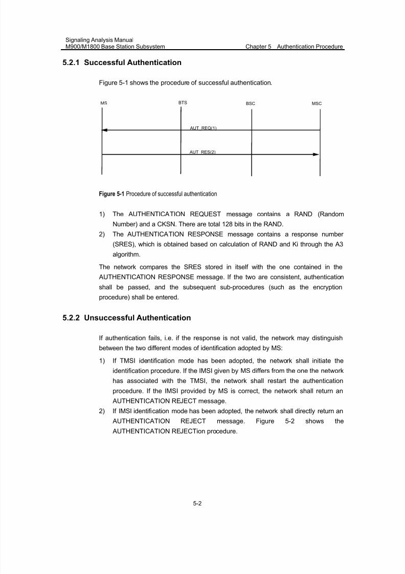
7/30/2019 Signaling Analysis Manual
http://slidepdf.com/reader/full/signaling-analysis-manual 101/290
Signaling Analysis ManualM900/M1800 Base Station Subsystem Chapter 5 Authentication Procedure
5-2
5.2.1 Successful Authentication
Figure 5-1 shows the procedure of successful authentication.
AUT_REQ(1)
AUT_RES(2)
MSCBSCBTSMS
Figure 5-1 Procedure of successful authentication
1) The AUTHENTICATION REQUEST message contains a RAND (Random
Number) and a CKSN. There are total 128 bits in the RAND.
2) The AUTHENTICATION RESPONSE message contains a response number
(SRES), which is obtained based on calculation of RAND and Ki through the A3
algorithm.
The network compares the SRES stored in itself with the one contained in the
AUTHENTICATION RESPONSE message. If the two are consistent, authentication
shall be passed, and the subsequent sub-procedures (such as the encryptionprocedure) shall be entered.
5.2.2 Unsuccessful Authentication
If authentication fails, i.e. if the response is not valid, the network may distinguish
between the two different modes of identification adopted by MS:
1) If TMSI identification mode has been adopted, the network shall initiate the
identification procedure. If the IMSI given by MS differs from the one the network
has associated with the TMSI, the network shall restart the authenticationprocedure. If the IMSI provided by MS is correct, the network shall return an
AUTHENTICATION REJECT message.
2) If IMSI identification mode has been adopted, the network shall directly return an
AUTHENTICATION REJECT message. Figure 5-2 shows the
AUTHENTICATION REJECTion procedure.
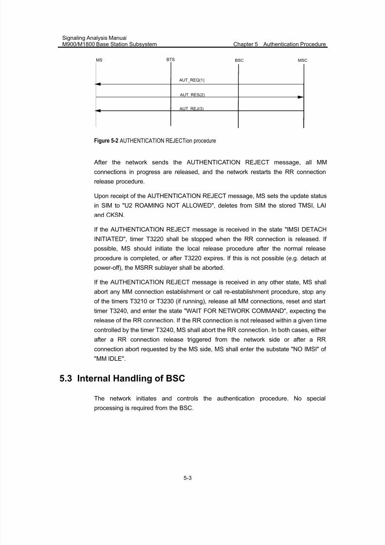
7/30/2019 Signaling Analysis Manual
http://slidepdf.com/reader/full/signaling-analysis-manual 102/290
Signaling Analysis ManualM900/M1800 Base Station Subsystem Chapter 5 Authentication Procedure
5-3
MSC
AUT_RES(2)
AUT_REJ(3)
BSCBTSMS
AUT_REQ(1)
Figure 5-2 AUTHENTICATION REJECTion procedure
After the network sends the AUTHENTICATION REJECT message, all MM
connections in progress are released, and the network restarts the RR connection
release procedure.
Upon receipt of the AUTHENTICATION REJECT message, MS sets the update status
in SIM to "U2 ROAMING NOT ALLOWED", deletes from SIM the stored TMSI, LAI
and CKSN.
If the AUTHENTICATION REJECT message is received in the state "IMSI DETACH
INITIATED", timer T3220 shall be stopped when the RR connection is released. If
possible, MS should initiate the local release procedure after the normal release
procedure is completed, or after T3220 expires. If this is not possible (e.g. detach at
power-off), the MSRR sublayer shall be aborted.
If the AUTHENTICATION REJECT message is received in any other state, MS shall
abort any MM connection establishment or call re-establishment procedure, stop any
of the timers T3210 or T3230 (if running), release all MM connections, reset and start
timer T3240, and enter the state "WAIT FOR NETWORK COMMAND", expecting the
release of the RR connection. If the RR connection is not released within a given time
controlled by the timer T3240, MS shall abort the RR connection. In both cases, either
after a RR connection release triggered from the network side or after a RR
connection abort requested by the MS side, MS shall enter the substate "NO IMSI" of
"MM IDLE".
5.3 Internal Handling of BSC
The network initiates and controls the authentication procedure. No special
processing is required from the BSC.
7/30/2019 Signaling Analysis Manual
http://slidepdf.com/reader/full/signaling-analysis-manual 103/290
Signaling Analysis ManualM900/M1800 Base Station Subsystem Chapter 5 Authentication Procedure
5-4
5.4 Abnormal Cases
5.4.1 RR Connection Failure
Upon detection of a RR connection failure before the AUTHENTICATION
RESPONSE message is received, the network shall release all MM connections (if
any) and abort any ongoing MM-specific procedure.
5.4.2 Expiry of Timer T3260
Before receipt of the AUTHENTICATION RESPONSE message, if timer T3260
expires, the network shall release the RR connection, abort the authentication
procedure and any ongoing MM-specific procedure, release all MM connections, andinitiate the RR connection release procedure.
5.4.3 SIM Unregistered
If the SIM of an MS has not been registered on the network side, the network will
directly return an AUTHENTICATION REJECT message to the MS.
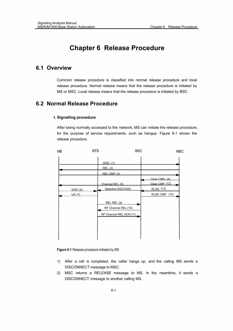
7/30/2019 Signaling Analysis Manual
http://slidepdf.com/reader/full/signaling-analysis-manual 104/290
Signaling Analysis ManualM900/M1800 Base Station Subsystem Chapter 6 Release Procedure
6-1
Chapter 6 Release Procedure
6.1 Overview
Common release procedure is classified into normal release procedure and local
release procedure. Normal release means that the release procedure is initiated by
MS or MSC. Local release means that the release procedure is initiated by BSC.
6.2 Normal Release Procedure
I. Signalling procedure
After being normally accessed to the network, MS can initiate the release procedure,
for the purpose of service requirements, such as hangup. Figure 6-1 shows the
release procedure.
DISC
REL
REL CMP
Clear CMD
Clear CMPChannel REL
REL IND
Deactive SACCH
RF Channel REL
RF Channel REL ACK
DISC
UA
RLSD
RLSD CMP
(1)
(2)
(3)
(4)
(5)
(6)
(7)
(8)
(9)
(10)
(11)
(12)
(13)
(14)
BTS BSC MSCMS
Figure 6-1 Release procedure initiated by MS
1) After a call is completed, the caller hangs up, and the calling MS sends a
DISCONNECT message to MSC.
2) MSC returns a RELEASE message to MS. In the meantime, it sends a
DISCONNECT message to another calling MS.
7/30/2019 Signaling Analysis Manual
http://slidepdf.com/reader/full/signaling-analysis-manual 105/290
Signaling Analysis ManualM900/M1800 Base Station Subsystem Chapter 6 Release Procedure
6-2
3) MS releases MM connections, and sends a RELEASE COMPLETE message to
MSC.
4) Upon receipt of the RELEASE COMPLETE message, MSC releases MM
connections, and sends a CLEAR COMMAND to BSC, notifying it to release theoccupied A interface resources and the logical channels on Um interface.
5) BSC delivers the channel RELEASE message to MS, requesting that MS and
BTS release the logical channels on Um interface.
6) MS sends a DISC frame to BTS, indicating that the logical channels have been
released.
7) BTS sends a UA frame to MS for acknowledgement. Upon receipt of the UA
frame, MS returns to the idle mode.
8) BSC sends a DEACTIVATE SACCH message to BTS, requesting that SACCH
be deactivated.
9) After BTS receives the DISC frame from MS, BTS returns a RELEASE
INDICATION message to BSC to indicate that MS has released the logic
channel on radio interface.
10) BSC sends a RF CHANNEL RELEASE message to BTS, requesting that the
physical channels on Um interface be released.
11) BTS returns a CHANNEL RELEASE ACKNOWLEDGE message to BSC,
indicating that the physical channels on Um interface have been released.
12) BSC sends a CLEAR COMPLETE message to MSC.
13) MSC sends a RLSD message to BSC, requesting the release of SCCP link
connection.
14) BSC returns a RLSD COMPLETE message to MSC, indicating that the SCCP
link connection has been released.
II. Procedure explanation
1) In Figure 6-1, 1~3 are to release call connections.
Note:
The procedure described in Figure 5-1 is a release procedure initiated by MS. For the release procedure
initiated by the network, except these 3 messages, which are transparently transmitted in reverse
directions, all the messages are the same as those in Figure 6-1.
2) 4~14 are to release radio resources.
After the connections of CC layer and MM layer are released, the network will send a
CLEAR COMMAND message to BSC, requesting the release of SCCP signalling
links. This message contains the call clearance cause values, such as "Handover
completed" or "Location update completed". If the release is caused by Um interface
message failure, radio link failure or equipment fault, BSC shall send the CLEAR
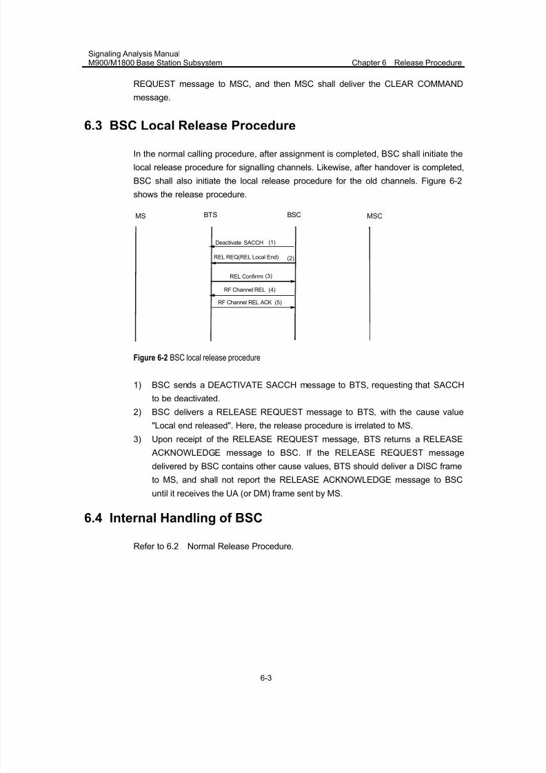
7/30/2019 Signaling Analysis Manual
http://slidepdf.com/reader/full/signaling-analysis-manual 106/290
Signaling Analysis ManualM900/M1800 Base Station Subsystem Chapter 6 Release Procedure
6-3
REQUEST message to MSC, and then MSC shall deliver the CLEAR COMMAND
message.
6.3 BSC Local Release Procedure
In the normal calling procedure, after assignment is completed, BSC shall initiate the
local release procedure for signalling channels. Likewise, after handover is completed,
BSC shall also initiate the local release procedure for the old channels. Figure 6-2
shows the release procedure.
BTS BSC MSCMS
REL Confirrm
Deactivate SACCH
RF Channel REL
RF Channel REL ACK
(1)
(3)
(4)
(5)
REL REQ(REL Local End) (2)
Figure 6-2 BSC local release procedure
1) BSC sends a DEACTIVATE SACCH message to BTS, requesting that SACCHto be deactivated.
2) BSC delivers a RELEASE REQUEST message to BTS, with the cause value
"Local end released". Here, the release procedure is irrelated to MS.
3) Upon receipt of the RELEASE REQUEST message, BTS returns a RELEASE
ACKNOWLEDGE message to BSC. If the RELEASE REQUEST message
delivered by BSC contains other cause values, BTS should deliver a DISC frame
to MS, and shall not report the RELEASE ACKNOWLEDGE message to BSC
until it receives the UA (or DM) frame sent by MS.
6.4 Internal Handling of BSC
Refer to 6.2 Normal Release Procedure.
7/30/2019 Signaling Analysis Manual
http://slidepdf.com/reader/full/signaling-analysis-manual 107/290
Signaling Analysis ManualM900/M1800 Base Station Subsystem
Chapter 7Mobile Originating Call Establishment Procedure
7-1
Chapter 7 Mobile Originating Call Establishment
Procedure
7.1 Overview
Mobile originating call services include (not including mobile-originated SMS)
z MS calls MS
z MS calls fixed telephone
7.2 Normal Procedure
As per assignment type, the mobile originating call establishment procedure can be
classified into 3 types, early assignment, late assignment and very early assignment.
The selection of early assignment and late assignment is determined by MSC. The
selection of very early assignment is determined by BSS as per the status of radio
resources.
7.2.1 Mobile Originating Call Establishment without OACSU (Early
Assignment)
Note:
OACSU denotes "Off-Air-Call-Set-Up".
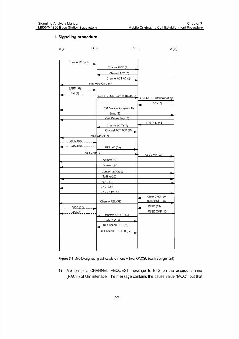
7/30/2019 Signaling Analysis Manual
http://slidepdf.com/reader/full/signaling-analysis-manual 108/290
Signaling Analysis ManualM900/M1800 Base Station Subsystem
Chapter 7Mobile Originating Call Establishment Procedure
7-2
I. Signaling procedure
Channel ACT (3)
Channel ACT ACK (4)
IMM ASS CMD (5)
BTS BSC MSCMS
Channel REQ (1)
SABM (6)
EST IND (CM Service REQ) (8)CR (CMP L3 information) (9)
CC (10)
Setup (12)
Call Proceeding (13)
ASS REQ (14)
ASS CMD (17)
SABM (18)
EST IND (20)
ASS CMP (21) ASS CMP (22)
Alerting (23)
Connect (24)
Connect ACK (25)
Talking (26)
DISC (27)
REL
REL CMP
Clear CMD (30)
Clear CMP (38)
CM Service Accepted (11)
Channel ACT (15)
Channel ACT ACK (16)
UA (19)
UA (7)
Channel REL (31)
REL IND (35)
Deactive SACCH (34)
RF Channel REL (36)
RF Channel REL ACK (37)
DISC (32)
UA (33)
RLSD (39)
RLSD CMP (40)
(28)
(29)
Channel RQD (2)
Figure 7-1 Mobile originating call establishment without OACSU (early assignment)
1) MS sends a CHANNEL REQUEST message to BTS on the access channel
(RACH) of Um interface. The message contains the cause value "MOC", but that
7/30/2019 Signaling Analysis Manual
http://slidepdf.com/reader/full/signaling-analysis-manual 109/290
Signaling Analysis ManualM900/M1800 Base Station Subsystem
Chapter 7Mobile Originating Call Establishment Procedure
7-3
value is not completely accurate, because it is indicated both in the mobile
originating call establishment procedure and IMSI detach procedure.
2) BTS sends a CHANNEL REQUIRED message to BSC.
3) Upon receipt of the CHANNEL REQUIRED message, BSC allocates a signalingchannel and sends a CHANNEL ACTIVATION message to BTS.
4) If the channel type is correct, upon receipt of the CHANNEL ACTIVATION
message, BTS opens the power amplifier on the specified channel, and sends a
CHANNEL ACTIVATION ACKNOWLEDGE message to BSC.
5) BSC sends an IMMEDIATE ASSIGNMENT COMMAND message to MS via BTS.
The message is sent on AGCH on Um interface.
6) MS sends an SABM frame on SDCCH to BTS to access the network.
7) BTS returns a UA frame on SDCCH for acknowledgement.
8) BTS sends an ESTABLISHMENT INDICATION message to BSC (This message
contains the accurate causes for MS's access. For example, different cause
values are indicated in the mobile originating call establishment procedure and
IMSI detach procedure). This message contains the contents of the CM
SERVICE REQUEST message.
9) BSC establishes the SCCP link connection on A interface, and sends a CM
SERVICE REQUEST message to MSC.
10) MSC returns a message to BSC to acknowledge the link connection.
11) MSC sends a CM SERVICE ACCEPTED message to MS. The message is sent
on SDCCH on Um interface.
12) The calling MS sends a SETUP message on SDCCH.
13) MSC sends a CALL PROCEEDING message to the calling MS. The message is
sent on SDCCH on Um interface.
14) MSC sends an ASSIGNMENT REQUEST message to BSC, which contains the
CIC allocated to A interface.
15) BSC allocates a TCH, and sends a CHANNEL ACTIVATION message to BTS.
16) If the channel type is correct, upon receipt of the CHANNEL ACTIVATION
message, BTS opens the power amplifier on the specified channel, starts to
receive the uplink information and sends a CHANNEL ACTIVATION
ACKNOWLEDGE message to BSC.
17) BSC sends an ASSIGNMENT COMMAND message to MS via BTS on SDCCH.
18) MS sends an SABM frame to BTS, to access the network on FACCH indicated in
the ASSIGNMENT COMMAND message.
19) BTS sends a UA frame for acknowledgement on FACCH.
20) BTS sends an ESTABLISHMENT INDICATION message to BSC.
21) After accessing the TCH, MS sends an ASSIGNMENT COMPLETE message to
BSC on FACCH.
22) After the radio traffic channel and terrestrial circuit are both successfully
connected, BSC sends an ASSIGNMENT COMPLETE message to MSC, and
regards this call in session state.
7/30/2019 Signaling Analysis Manual
http://slidepdf.com/reader/full/signaling-analysis-manual 110/290
Signaling Analysis ManualM900/M1800 Base Station Subsystem
Chapter 7Mobile Originating Call Establishment Procedure
7-4
23) MSC sends an ALTERING message to the calling MS. The calling MS will hear
the ringback. The message is sent on FACCH on Um interface.
24) MSC sends a CONNECT message to MS. The message is sent on FACCH on
Um interface.25) The calling MS returns a CONNECT ACKNOWLEDGE message on FACCH to
MSC.
26) The calling MS and called MS enters the session state.
27) After the conversation is over, the calling MS hangs up and sends a
DISCONNECT message on FACCH.
28) MSC sends a RELEASE message to MS. The message is sent on FACCH on
Um interface.
29) MS returns a RELEASE COMPLETE message. The message is sent on FACCH
on Um interface.
30) MSC sends a CLEAR COMMAND message to BSC. Upon receipt of the
message, BSC initiates the release procedure. See Chapter 5 for the description
of the subsequent release procedure.
31) BSC sends a CHANNEL RELEASE message to MS through BTS, The message
is sent on FACCH on Um interface.
32) MS sends DISC frame on FACCH.
33) BTS returns UA frame on FACCH.
II. Procedure explanation
1) In Figure 7-1, 1~8 refer to the random access procedure and immediateassignment procedure. In the two procedures, BSS allocates signaling channels
to MS.
2) Between 10~11, there may exist an authentication procedure, ciphering mode
setting procedure and classmark interrogation procedure (updating procedure).
3) As per different data configuration of MSC, after the link connection is
established on A interface, MSC may not immediately deliver the CM SERVICE
ACCEPTED message. Instead, it may proceed as follows.
4) Initiate the ciphering mode setting procedure by delivering a Cipher Mode
Command (In that case, MSC shall not deliver the CM Service Accepted
message again).
5) Initiate the authentication procedure by delivering an AUTHENTICATION
REQUEST message.
6) Initiate the classmark updating procedure by delivering a CLASSMARK UPDATE
message.
7) In addition, if [ECSC] in BSC data configuration is set to "Yes", the dual-band MS
shall report a CLASSMARK CHANGE message after it reports an
ESTABLISHMENT INDICATION message.
8) 14~22 refer to the TCH assignment procedure.

7/30/2019 Signaling Analysis Manual
http://slidepdf.com/reader/full/signaling-analysis-manual 111/290
Signaling Analysis ManualM900/M1800 Base Station Subsystem
Chapter 7Mobile Originating Call Establishment Procedure
7-5
In this procedure, BSS allocates the resources such as TCHs, A interface circuit, etc.
to MS.
9) 30~40 refer to the release procedure.
The procedure shown in Figure 7-1 is a release procedure in which the calling MS
first hangs up. The logical channels on Um interface are released prior to the physical
channels.
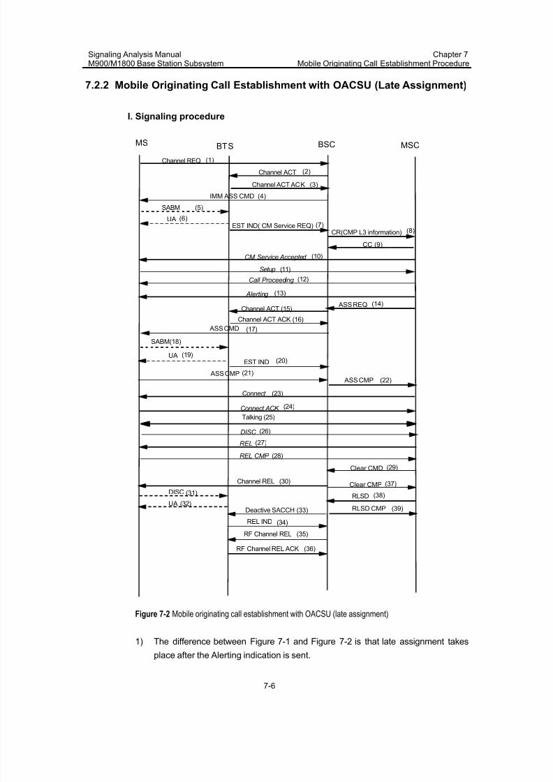
7/30/2019 Signaling Analysis Manual
http://slidepdf.com/reader/full/signaling-analysis-manual 112/290
Signaling Analysis ManualM900/M1800 Base Station Subsystem
Chapter 7Mobile Originating Call Establishment Procedure
7-6
7.2.2 Mobile Originating Call Establishment with OACSU (Late Assignment)
I. Signaling procedure
Channel ACT
Channel ACT ACK
IMM ASS CMD
BTS BSC MSCMS
Channel REQ
SABM
EST IND( CM Service REQ)CR(CMP L3 information)
CC
Setup
Call Proceeding
ASS REQ
ASS CMD
SABM(18)
EST IND
ASS CMP ASS CMP
Alerting
Connect
Connect ACK
Talking (25)
DISC
REL
REL CMP
Clear CMD
Clear CMP
CM Service Accepted
Channel ACT (15)
Channel ACT ACK (16)
UA
UA
Channel REL
REL IND
Deactive SACCH
RF Channel REL
RF Channel REL ACK
DISC
UARLSD
RLSD CMP
(1)
(2)
(3)
(4)
(5)
(6)(7)
(8)
(9)
(10)
(11)
(12)
(13)
(14)
(17)
(19)(20)
(21)(22)
(23)
(24)
(26)
(27)
(28)
(29)
(30)
(31)
(32)(33)
(34)
(35)
(36)
(37)
(38)
(39)
Figure 7-2 Mobile originating call establishment with OACSU (late assignment)
1) The difference between Figure 7-1 and Figure 7-2 is that late assignment takes
place after the Alerting indication is sent.
7/30/2019 Signaling Analysis Manual
http://slidepdf.com/reader/full/signaling-analysis-manual 113/290
Signaling Analysis ManualM900/M1800 Base Station Subsystem
Chapter 7Mobile Originating Call Establishment Procedure
7-7
2) The advantage of late assignment lies in that it can save the seizure time of
TCHs.
3) The disadvantage of late assignment is that if the subsequent assignment is
unsuccessful, the called MS can only hear the ring but cannot establish aconnection, thus leading to user complaints. Therefore, in actual application, this
procedure is generally not adopted. Instead, the procedure in Figure 7-1 is
adopted.
II. Procedure explanation
For relevant explanation, please refer to 7.2.1 Mobile Originating Call Establishment
without OACSU (Early Assignment). The procedure in Figure 7-2 is a procedure in
which the calling MS first hangs up.
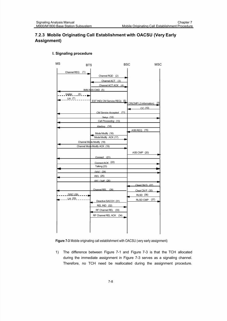
7/30/2019 Signaling Analysis Manual
http://slidepdf.com/reader/full/signaling-analysis-manual 114/290
Signaling Analysis ManualM900/M1800 Base Station Subsystem
Chapter 7Mobile Originating Call Establishment Procedure
7-8
7.2.3 Mobile Originating Call Establishment with OACSU (Very Early
Assignment)
I. Signaling procedure
Channel ACT
Channel ACT ACK
IMM ASS CMD
BTS BSC MSCMS
Channel RQD
SABM
EST IND( CM Service REQ)CR(CMP L3 information)
CC
Setup
Call Proceeding
ASS REQ
ASS CMP
Alerting
Connect
Connect ACK
Talking (23)
DISC
REL
REL CMP
Clear CMD
Clear CMP
CM Service Accepted
Mode Modify (16)
Mode Modify ACK (17)
UA
Channel REL
REL IND
Deactive SACCH
RF Channel REL
RF Channel REL ACK
DISC
UA
RLSD
RLSD CMP
(1)
(3)
(4)
(5)
(6)
(7)(8)
(9)
(10)
(11)
(12)
(13)
(14)
(15)
(20)
(21)
(22)
(24)
(25)
(26)
(27)
(28)
(29)
(30)(31)
(32)
(33)
(34)
(35)
(36)
(37)
Channel Mode Modify (18)
Channel Mode Modify ACK (19)
Channel REQ
(2)
Figure 7-3 Mobile originating call establishment with OACSU (very early assignment)
1) The difference between Figure 7-1 and Figure 7-3 is that the TCH allocated
during the immediate assignment in Figure 7-3 serves as a signaling channel.
Therefore, no TCH need be reallocated during the assignment procedure.
7/30/2019 Signaling Analysis Manual
http://slidepdf.com/reader/full/signaling-analysis-manual 115/290
Signaling Analysis ManualM900/M1800 Base Station Subsystem
Chapter 7Mobile Originating Call Establishment Procedure
7-9
Instead, the TCH allocated in the immediate assignment procedure is adjusted
as a TCH by using the MODE MODIFY message.
2) Very early assignment generally takes place if there is no free SDCCH for
allocation during immediate assignment, but there are free TCHs and immediateassignment of TCHs is allowed in BSC data configuration.
II. Procedure explanation
For relevant explanation, refer to 7.2.1 Mobile Originating Call Establishment
without OACSU (Early Assignment). The procedure in Figure 7-3 is a procedure in
which the calling MS first hangs up.
7.3 Internal Handling of BSC
The internal handling of the BSC is given below:
1) Upon receipt of the CHANNEL REQUIRED message from the BTS, the BSC
allocates a signaling channel based on the channel type and channel allocation
algorithm required by the [Radio channel management control table], [HW II
Channel Allocation table] and the “TCH immediate assignment” field in the [Cell
call control table].
2) Upon receipt of the ESTABLISHMENT INDICATION message in the random
access procedure, the BSC adds the CGI of the current cell to the CM SERVICE
REQUEST message based on the [BSC Cell Table] and sends the message to
the MSC.
3) Upon receipt of the ASSIGNMENT REQUEST message from the MSC, the BSC
checks the channel type. Then it checks whether the data service is supported
based on the “Data Service allowed” field in the [Cell Configuration Table]. It
returns an ASSIGNMENT FAILURE message if the data service is not
supported.
4) The BSC checks the [Trunk Circuit Table] based on the CIC in the ASSIGNMENT
REQUEST message for whether the CIC exists. Then it checks whether the
circuit pool, the channel type in the ASSIGNMENT REQUEST message and the
supporting capability of the FTC board conflict. It returns an ASSIGNMENTFAILURE message to the MSC upon conflict.
5) Upon receipt of the ASSIGNMENT COMPLETE message from the MS, the BSC
fills in the ASSIGNMENT COMPLETE message over interface A interface based
on the “A-interface Phase flag” field in the [Local Office Information Table]. Then
it sends the message to the MSC.
7.4 Abnormal Cases
In the cases of loss of messages on Um interface, call interruption, hangup, abnormal
operation of transport/NSS/BSS equipment, the procedure may not be performed
7/30/2019 Signaling Analysis Manual
http://slidepdf.com/reader/full/signaling-analysis-manual 116/290
Signaling Analysis ManualM900/M1800 Base Station Subsystem
Chapter 7Mobile Originating Call Establishment Procedure
7-10
normally. In addition, if MS resends multiple CHANNEL REQUEST messages during
an access attempt, BSS shall activate multiple signaling channels correspondingly.
Actually, MS shall only seize 1 signaling channel. Because no ESTABLISH
INDICATION message can be received from MS by other channels, other channelsshall be released upon timeout.
Because there are various causes for abnormal procedures, here, merely the
common cases are described.
7.4.1 Abnormal Random Access/Immediate Assignment Procedure
I. ESTABLISH INDICATION message cannot be received after a channel has
been activated
Generally, there are the following causes for this problem.
1) Due to defect design that does not comply with the protocols, MS resends
multiple CHANNEL REQUEST messages. As a result, BSS allocates and
activates too many signaling channels.
Even if BSS runs normally, during an access attempt, MS may resend multiple
CHANNEL REQUEST messages. As a result, BSS activates multiple signaling
channels. Actually, MS shall only seize 1 signaling channel. Because no
ESTABLISH INDICATION message can be received from MS by other channels,
other channels shall be released when the T3101 timer expires.2) On Um interface, uplink signals can be received normally, whereas, downlink
signals cannot be properly received by MS.
By tracing the Um interface on MS side, it may be found that MS cannot receive
the relevant information from BTS after it sends a CHANNEL REQUEST
message.
In that case, the user should check whether the uplink/downlink Rx level and Rx
quality are normal. If MS is not far from BTS, but the signals are of low Rx level
and poor Rx quality, the user should check whether the antenna & feeder of BTS,
the antenna of MS, battery, etc. work normally.
3) Tx-integer and CCCH are improperly configured in BSC data configuration.
The configuration mode of Tx-integer and CCCH has impact upon the
retransmission interval of MS's CHANNEL REQUEST message.
II. BSC sends an IMMEDIATE ASSIGNMENT REJECT message
If BSC sends an IMMEDIATE ASSIGNMENT REJECT message to MS upon receipt
of a CHANNEL REQUEST message, generally, the causes may be as follows.
7/30/2019 Signaling Analysis Manual
http://slidepdf.com/reader/full/signaling-analysis-manual 117/290
Signaling Analysis ManualM900/M1800 Base Station Subsystem
Chapter 7Mobile Originating Call Establishment Procedure
7-11
1) BSC cannot find an appropriate signaling channel (Generally, the signaling
channel is SDCCH, but it can also be TCH) to allocate to the MS, generally,
because no signaling channel is available, e.g. all signaling channels are in busy
state or the channels have been blocked.2) BTS returns CHANNEL ACTIVATION NEGATIVE ACKNOWLEDGE messages to
BSC after it delivers a CHANNEL ACTIVATION message to MS.
If BTS returns many CHANNEL ACTIVATION NEGATIVE ACKNOWLEDGE
messages to BSC, the problem generally lies in that the unstable transmission on
Abis interface has lead to the inconsistency between the channel states of BSC and
BTS, or abnormality has occurred to a board in BTS.
7.4.2 MSC Directly Delivers DISCONNECT to Clear the Call, Instead of
Delivering the Assignment Request
In the MS call procedure, after the immediate assignment procedure is finished, the
following procedure is assignment. Sometimes MSC doesn't send ASSIGNMENT
REQUEST message, but send DISCONNECT message to MS, and then disconnect
the call. After this problem occurs, usually, a large quantity of MSs shall complain
that calls cannot be put through. In that case, the following points should mainly be
checked.
1) The state of A interface circuit on MSC side.
2) The consistency between A interface data of MSC and A interface data of BSC,
especially circuit pool data.
7.4.3 Abnormal Assignment Procedure
I. ASSIGNMENT FAILURE
Upon receipt of an ASSIGNMENT REQUEST message, BSC returns an
ASSIGNMENT FAILURE message, instead of an ASSIGNMENT COMPLETE
message. The common causes are as follows.
1) There is no appropriate TCH for allocation in BSC.There is no appropriate TCH for allocation in BSC, possibly because all TCHs are in
busy state or have been blocked.
The ASSIGNMENT FAILURE message returned by BSC contains the cause value
"No radio resource".
In that case, the user can solve the problem by BTS expansion (adding TRX),
modifying the access threshold and open the direct re-attempt permit switch.
2) MS fails to access the TCH, and sends an ASSIGNMENT FAILURE message on
the signaling channel.
7/30/2019 Signaling Analysis Manual
http://slidepdf.com/reader/full/signaling-analysis-manual 118/290
Signaling Analysis ManualM900/M1800 Base Station Subsystem
Chapter 7Mobile Originating Call Establishment Procedure
7-12
Due to the particularity of the transmission on Um interface, this problem is actually
the most common problem in the network, and cannot be solved completely. If this
problem occurs frequently, it may lead to user complaints. The major points to be
checked are the antenna & feeder, the relevant boards in BTS, and access-relatedparameters in BSC data configuration.
3) On BSC side, A interface circuit is found abnormal, e.g. The CIC contained in the
ASSIGNMENT REQUEST message is not available.
In that case, the user should check the A interfaces.
4) Abnormality occurs to the relevant equipment in BSC.
The ASSIGNMENT FAILURE message returned by BSC generally contains the cause
value "Equipment failure".
In that case, the major points to be checked are as follows.z The boards and their respective backplanes and optical fiber that are related to
the inter-module communication in BSC, such as GMC2, GMCC, GSNT, GOPT
and GFBI.
z The boards related to A interface, such as E3Ms, TCSMs and their backplanes
5) Abnormality occurs to the transmission on interface A.
II. Directed Retry
Because there is no appropriate TCH for allocation, and the directed re-attempt
permit switch is set to "On" in BSC data configuration, upon receipt of an ASSIGNMENT REQUEST message from MSC, BSC shall initiate a directed retry
handover procedure as per the actual situation, so that MS can directly attempt to
access other cells.
7.4.4 Abnormal Procedure Cause by Call Interruption
Call interruption might occur in any procedure to the calling/called MS, and as a result,
the subsequent procedures cannot be completed normally. For example, after BSC
receives an ASSIGNMENT REQUEST message from MSC, call interruption occurs to
MS on signaling channel. In that case, the assignment procedure probably is not be
finished (For example, the channel is just assigned and the Assignment Command is
not sent) BSC probably shall not return an ASSIGNMENT COMPLETE or
ASSIGNMENT FAILURE message to MSC. Instead, it shall send a CLEAR
REQUEST message.
7.4.5 Abnormal Procedure Caused by Hangup
The calling/called MS may hang up in any procedure, and as a result, the subsequent
procedures cannot be completed normally. For example, after BSC receives an
7/30/2019 Signaling Analysis Manual
http://slidepdf.com/reader/full/signaling-analysis-manual 119/290
Signaling Analysis ManualM900/M1800 Base Station Subsystem
Chapter 7Mobile Originating Call Establishment Procedure
7-13
ASSIGNMENT REQUEST message from MSC, MS suddenly hangs up. In that case,
the call establishment may be already terminated before BSC returns an
ASSIGNMENT COMPLETE or ASSIGNMENT FAILURE message to MSC. As a result,
the procedure is neither a successful assignment procedure (BSC sends an ASSIGNMENT COMPLETE message), nor an unsuccessful assignment procedure
(BSC sends an ASSIGNMENT FAILURE message).
7.4.6 Abnormal Procedure Caused by MSC Clearing
After the link connection on A interface is established, due to some causes, MSC may
send a CLEAR COMMAND or DISCONNECT message to BSC, and as a result, the
subsequent procedures cannot be completed normally. For example, after BSC
receives an ASSIGNMENT REQUEST message from MSC, MS suddenly hangs up.
In that case, the call establishment may be already terminated before BSC returns an
ASSIGNMENT COMPLETE or ASSIGNMENT FAILURE message to MSC. As a result,
the procedure is neither a successful assignment procedure (BSC sends an
ASSIGNMENT COMPLETE message), nor an assignment failure procedure (BSC
sends an ASSIGNMENT FAILURE message).
If this problem frequently occurs, the following points should be analyzed specially.
1) The cause value contained in the CLEAR COMMAND message
If a call terminates normally, the CLEAR COMMAND message generally contains the
cause value "Call control". Otherwise, it may contain the cause value of "ProtocolError", or "Equipment failure", etc.
2) The time difference between the previous message and the CLEAR COMMAND
or DISCONNECT message in the procedure
The user can analyze the time difference between the two successive messages, to
see whether there is possibility that the abnormal procedure has been triggered by
timeout.
7/30/2019 Signaling Analysis Manual
http://slidepdf.com/reader/full/signaling-analysis-manual 120/290
Signaling Analysis ManualM900/M1800 Base Station Subsystem
Chapter 8Mobile Terminating Call Establishment Procedure
8-1
Chapter 8 Mobile Terminating Call Establishment
Procedure
8.1 Overview
Mobile terminating calls include the calls initiated by MS and those initiated by fixed
telephones.
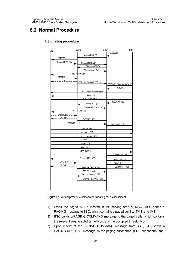
7/30/2019 Signaling Analysis Manual
http://slidepdf.com/reader/full/signaling-analysis-manual 121/290
Signaling Analysis ManualM900/M1800 Base Station Subsystem
Chapter 8Mobile Terminating Call Establishment Procedure
8-2
8.2 Normal Procedure
I. Signaling procedure
Channel ACT (6)
Channel ACT ACK (7)
IMM ASS CMD (8)
BTS BSC MSCMS
Channel REQ (4)
SABM (9)
EST IND( Paging RESP) (11)CR(CMP L3 information) (12)
CC (13)
Setup (15)
Call Confirmmed (16)
ASS REQ (17)
ASS CMD
SABM (21)
EST IND
ASS CMP ASS CMP
Alerting
Connect
Connect ACK Talking
DISC
REL (30)
REL CMP
Clear CMD
Clear CMP
CM Service Accepted (14)
Channel ACT (18)
Channel ACT ACK (19)
UA
UA (10)
Channel REL
REL IND
Deactive SACCH
RF Channel REL
RF Channel REL ACK
DISC
UARLSD
RLSD CMP
(20)
(22)(23)
(24)(25)
(26)
(27)
(28)
(29)
(31)
(32)
(33)
(34)
(35)(36)
(37)
(38)
(39)
(40)
(41)
(42)
paging (1)paging CMD (2)
paging REQ (3)
Channel RQD (5)
Figure 8-1 Normal procedure of mobile terminating call establishment
1) When the paged MS is located in the serving area of MSC, MSC sends a
PAGING message to BSC, which contains a paged cell list, TMSI and IMSI.
2) BSC sends a PAGING COMMAND message to the paged cells, which contains
the relevant paging subchannel Nos. and the occupied timeslot Nos.
3) Upon receipt of the PAGING COMMAND message from BSC, BTS sends a
PAGING REQUEST message on the paging subchannel (PCH subchannel) that
7/30/2019 Signaling Analysis Manual
http://slidepdf.com/reader/full/signaling-analysis-manual 122/290
Signaling Analysis ManualM900/M1800 Base Station Subsystem
Chapter 8Mobile Terminating Call Establishment Procedure
8-3
belongs to the paging group. This message contains the IMSI or TMSI of the
paged MS.
4) MS sends a CHANNEL REQUEST message on RACH if it finds itself paged
after decoding the paging message.5) For other messages, please refer to Chapter 7 Mobile Originating Call
Establishment Procedure.
II. Procedure explanation
1) Paging signaling procedure
In Figure 8-1, 1~11 refer to the paging signaling procedure, in which, BSS initiates
paging and allocates signaling channels to MS.
2) Classification of assignment procedure
As per assignment type, the assignment procedure can be classified into 3 types,early assignment, late assignment and very early assignment. Except the late
assignment procedure, in which, the ASSIGNMENT REQUEST message is delivered
after MSC has received a CONNECT message from MS, the other procedures are
basically the same as the mobile originating call establishment procedure. For details,
please refer to Chapter 7 Mobile Originating Call Establishment Procedure.
8.3 Internal Handling of BSC
The internal handling of the BSC is given below:
1) Upon receipt of the PAGING message over interface A, the BSC checks whether
to enable flow control based on the [Flow Control Parameter Table].
2) The BSC transfers the PAGING message to the relevant BM module after
checking the [Cell module information table].
3) The BM module computes a paging group and sends it out.
4) The BM module computes the paging group based on the TMSI or IMSI in the
PAGING message and on the following parameters in the [System information
table]: “BS_AG_BLKS_RES”, “CCCH-CONF” and “BS_PA_MFRMS”.
8.4 Abnormal Cases
This section only analyzes the common abnormal procedures. For the other abnormal
procedures, refer to Chapter 7 Mobile Originating Call Establishment Procedure.
Upon paging failure, the MSC prompts voice information to the calling party, indicating
that the called MS is outside the serving area or cannot be connected. In this case,
trace the signaling on interfaces A and Abis to check whether the paging failure is
caused by:
z no PAGING COMMAND on interface A
z no PAGING COMMAND on interface Abis
7/30/2019 Signaling Analysis Manual
http://slidepdf.com/reader/full/signaling-analysis-manual 123/290
Signaling Analysis ManualM900/M1800 Base Station Subsystem
Chapter 8Mobile Terminating Call Establishment Procedure
8-4
z no PAGING RESPONSE on interface Abis
z no PAGING RESPONSE on interface A
8.4.1 No PAGING COMMAND on Interface A
Through signaling tracing over interface A, the MSC is detected that it has not sent a
PAGING message to the BSC. In this case, check the data configuration and MS
information in the MSC/VLR and HLR on the NSS side. Additionally, power off the
called MS, power it on and make a test call to check whether the MS is normal.
I. Check user data in VLR
When an MS is paged, MSC judges the current state of the MS as per the user data
(including MS active state, registered LA, cell information, etc.), and thus decides
whether to send the PAGING message or how to send the PAGING message.
If the MS state has changed (e.g. the MS is switched off, or has entered a different
LA), but due to various reasons, the MS has not performed registration in the network
normally, and has not updated the user data in VLR, the MS may probably be unable
to be paged.
In that case, the MS is required to initiate a location updating procedure, so that the
user data in VLR can be ensured correct. The period of periodic location update is
indicated for MS by BSC in the system information. On MSC side, there is also a
location update period. Refer to Chapter 4 Location Update Procedure. The twoparameters of BSC and MSC must satisfy a certain relationship, which requires that
MS must initiate a location update procedure within the period specified in MSC.
Generally, the location update period configured in BSC is shorter than that in MSC.
II. Check RA- or cell-related parameter settings in MSC
If a routing area or cell related parameter is incorrectly set in the MSC, the
transmission of the PAGING message might fail. For example, if a wrong target BSC
is selected, the PAGING message that should have been sent to the local BSC will be
sent to another BSC.
8.4.2 No PAGING COMMAND on Interface Abis
Upon receipt of the PAGING message from the MSC, the BSC detects that the MSC
has not sent PAGING COMMAND to the BTS over interface Abis. In this case, check
the operations and data configuration in the BSC.
7/30/2019 Signaling Analysis Manual
http://slidepdf.com/reader/full/signaling-analysis-manual 124/290
Signaling Analysis ManualM900/M1800 Base Station Subsystem
Chapter 8Mobile Terminating Call Establishment Procedure
8-5
I. Check whether flow control is enabled
z Check whether the system load suddenly increases due to centralized
transmission of short messages or mass access bursts
Query the traffic statistics about “Number of immediate assignment requests” and
“Number of CS service paging requests” in the BSC overall performance
measurement. Compare the query results before and after the failure in paging the
called MS and check whether the flow control function is enabled.
z Check whether the flow control parameter is correctly set
II. Check relevant data configuration
z Check whether the CGI information in BSC data configuration is consistent with
the LAC information in the PAGING message over interface A
Log in to the BSC Data Management System. Click [BSC/Cell/Cell Module
Information Table] to check whether the parameters in the table are correctly set.
Additionally, if a RA- or cell-related parameter is not correctly set in the MSC, for
example, a wrong target BSC is selected, the PAGING COMMAND message cannot
be successfully sent over interface Abis.
z Check whether the settings for the BSC parameters that will affect paging groups
are correct
Check whether the following parameters in the [System information table] are
correctly set: “BS_AG_BLKS_RES”, “CCCH-CONF” and “BS_PA_MFRMS”.
III. Check inter-module communications in BSC
Because Huawei BSC adopts multi-module structure, upon receipt of a PAGING
message from MSC, BSC performs paging as per the LA cell information in the
PAGING message. In that case, the PAGING COMMAND message to be delivered to
BTS may be transferred between the modules in BSC. If an exception occurs to the
inter-module communications, no PAGING COMMAND message can be transferred
between the modules or sent o interface Abis.
Abnormal inter inter-module communications can be verified through relevant BSC
alarms.
8.4.3 No PAGING RESPONSE on Interface Abis
Through signaling tracing over interface Abis, the BSC is detected that it has not
received the Establishment Indication (PAGING RESPONSE) after sending PAGING
COMMAND to the BTS. In this case, check the relevant data configuration and radio
signal coverage.
7/30/2019 Signaling Analysis Manual
http://slidepdf.com/reader/full/signaling-analysis-manual 125/290
Signaling Analysis ManualM900/M1800 Base Station Subsystem
Chapter 8Mobile Terminating Call Establishment Procedure
8-6
I. PCH or AGCH overloaded due to centralized short message transmission or
mass access bursts
Query the traffic statistics about “Number of immediate assignment requests” and
“Number of CS service paging requests” in the cell overall performance measurement.
Compare the query results before and after the failure in paging the called MS and
check whether the PCH or AGCH is overloaded due to centralized short message
transmission or mass access bursts.
II. Check the called MS or SIM in it
If an MS of a certain model or lot cannot provide the required processing capability or
if the SIM card in the MS is unavailable, the sending of the PAGING message might
fail. In this case, perform the following:
z Insert a different (normal) SIM into the called MS to check whether the original
SIM in the MS is functional
z Insert the SIM in the called MS into an MS from a different manufacturer to check
whether the MS is normal
III. Check BTS by making test calls in a different cell
z Make a test call in a different cell under the same BTS
z Make a test call under a different BTS of the same type
z Make a test call under a BTS of a different type
z Make a test call under a BTS from a different manufacturer
IV. Check data configuration in BSC
z Check the settings for the parameters that will affect paging groups
Check whether the following parameters in the [System information table] are
correctly configured: “BS_AG_BLKS_RES”, “CCCH-CONF”, “BS_PA_MFRMS”,
“Tx-integer“ and “MS MAX retrans”.
z Check the setting for “location updating period” in BSC and that in MSC
Check the [System information table] for the configuration of “T3212”.
The value of "T3212" in the MSC must be greater than that in the BSC.
Refer to Chapter 4 Location Update Procedure.
V. Check radio signal coverage
Due to the problem of radio signal coverage, there might be some blind coverage
areas. The MS that has entered a blind coverage area cannot receive the PAGING
REQUEST message. In that case, the MS cannot be paged.
Such cases, if any, only exist in partial areas.

7/30/2019 Signaling Analysis Manual
http://slidepdf.com/reader/full/signaling-analysis-manual 126/290
Signaling Analysis ManualM900/M1800 Base Station Subsystem
Chapter 8Mobile Terminating Call Establishment Procedure
8-7
8.4.4 No PAGING RESPONSE on Interface A
Through signaling tracing on interface Abis, the BSC is detected that it has received
an Establishment Indication (PAGING RESPONSE) message from the BTS but thismessage is not reported over interface A.
Such case hardly occurs and is omitted here.
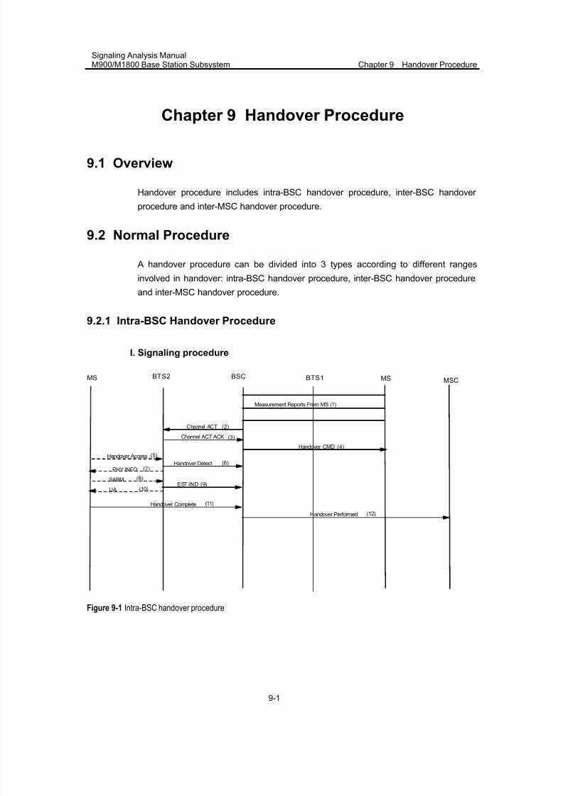
7/30/2019 Signaling Analysis Manual
http://slidepdf.com/reader/full/signaling-analysis-manual 127/290
Signaling Analysis ManualM900/M1800 Base Station Subsystem Chapter 9 Handover Procedure
9-1
Chapter 9 Handover Procedure
9.1 Overview
Handover procedure includes intra-BSC handover procedure, inter-BSC handover
procedure and inter-MSC handover procedure.
9.2 Normal Procedure
A handover procedure can be divided into 3 types according to different rangesinvolved in handover: intra-BSC handover procedure, inter-BSC handover procedure
and inter-MSC handover procedure.
9.2.1 Intra-BSC Handover Procedure
I. Signaling procedure
BTS2 BSCMSCMS
Measurement Reports From MS (1)
(12)
MS
Handover CMD
Handover Access
Handover Detect
Handover Complete
Channel ACT (2)
Channel ACT ACK (3)
(4)
(5)
(6)
SABM (8)EST IND (9)
PHY INFO (7)
BTS1
Handover Performed
(10)UA
(11)
Figure 9-1 Intra-BSC handover procedure
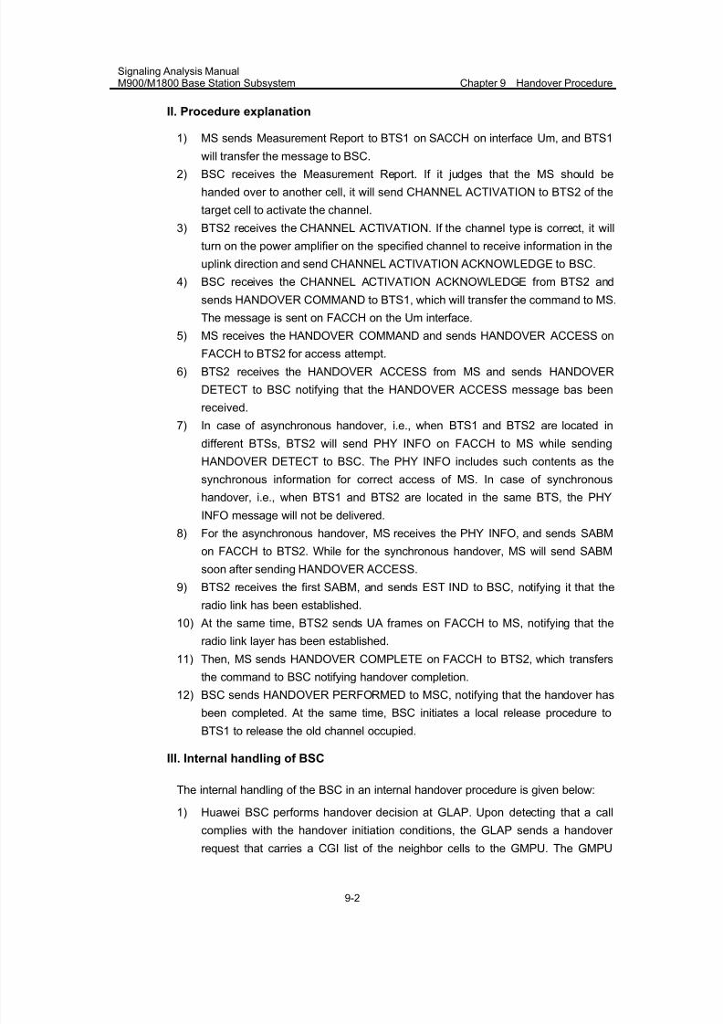
7/30/2019 Signaling Analysis Manual
http://slidepdf.com/reader/full/signaling-analysis-manual 128/290
Signaling Analysis ManualM900/M1800 Base Station Subsystem Chapter 9 Handover Procedure
9-2
II. Procedure explanation
1) MS sends Measurement Report to BTS1 on SACCH on interface Um, and BTS1
will transfer the message to BSC.
2) BSC receives the Measurement Report. If it judges that the MS should be
handed over to another cell, it will send CHANNEL ACTIVATION to BTS2 of the
target cell to activate the channel.
3) BTS2 receives the CHANNEL ACTIVATION. If the channel type is correct, it will
turn on the power amplifier on the specified channel to receive information in the
uplink direction and send CHANNEL ACTIVATION ACKNOWLEDGE to BSC.
4) BSC receives the CHANNEL ACTIVATION ACKNOWLEDGE from BTS2 and
sends HANDOVER COMMAND to BTS1, which will transfer the command to MS.
The message is sent on FACCH on the Um interface.
5) MS receives the HANDOVER COMMAND and sends HANDOVER ACCESS onFACCH to BTS2 for access attempt.
6) BTS2 receives the HANDOVER ACCESS from MS and sends HANDOVER
DETECT to BSC notifying that the HANDOVER ACCESS message bas been
received.
7) In case of asynchronous handover, i.e., when BTS1 and BTS2 are located in
different BTSs, BTS2 will send PHY INFO on FACCH to MS while sending
HANDOVER DETECT to BSC. The PHY INFO includes such contents as the
synchronous information for correct access of MS. In case of synchronous
handover, i.e., when BTS1 and BTS2 are located in the same BTS, the PHY
INFO message will not be delivered.
8) For the asynchronous handover, MS receives the PHY INFO, and sends SABM
on FACCH to BTS2. While for the synchronous handover, MS will send SABM
soon after sending HANDOVER ACCESS.
9) BTS2 receives the first SABM, and sends EST IND to BSC, notifying it that the
radio link has been established.
10) At the same time, BTS2 sends UA frames on FACCH to MS, notifying that the
radio link layer has been established.
11) Then, MS sends HANDOVER COMPLETE on FACCH to BTS2, which transfers
the command to BSC notifying handover completion.
12) BSC sends HANDOVER PERFORMED to MSC, notifying that the handover has
been completed. At the same time, BSC initiates a local release procedure to
BTS1 to release the old channel occupied.
III. Internal handling of BSC
The internal handling of the BSC in an internal handover procedure is given below:
1) Huawei BSC performs handover decision at GLAP. Upon detecting that a call
complies with the handover initiation conditions, the GLAP sends a handover
request that carries a CGI list of the neighbor cells to the GMPU. The GMPU
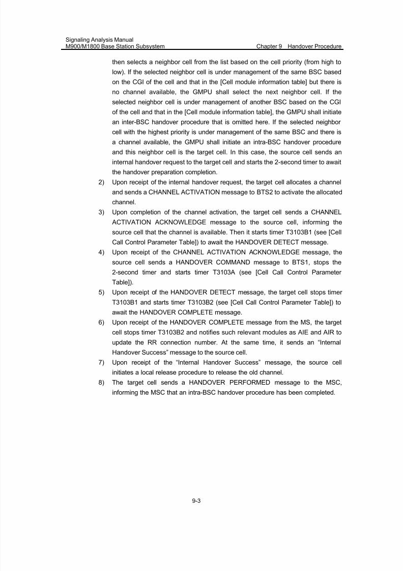
7/30/2019 Signaling Analysis Manual
http://slidepdf.com/reader/full/signaling-analysis-manual 129/290
Signaling Analysis ManualM900/M1800 Base Station Subsystem Chapter 9 Handover Procedure
9-3
then selects a neighbor cell from the list based on the cell priority (from high to
low). If the selected neighbor cell is under management of the same BSC based
on the CGI of the cell and that in the [Cell module information table] but there is
no channel available, the GMPU shall select the next neighbor cell. If theselected neighbor cell is under management of another BSC based on the CGI
of the cell and that in the [Cell module information table], the GMPU shall initiate
an inter-BSC handover procedure that is omitted here. If the selected neighbor
cell with the highest priority is under management of the same BSC and there is
a channel available, the GMPU shall initiate an intra-BSC handover procedure
and this neighbor cell is the target cell. In this case, the source cell sends an
internal handover request to the target cell and starts the 2-second timer to await
the handover preparation completion.
2) Upon receipt of the internal handover request, the target cell allocates a channel
and sends a CHANNEL ACTIVATION message to BTS2 to activate the allocated
channel.
3) Upon completion of the channel activation, the target cell sends a CHANNEL
ACTIVATION ACKNOWLEDGE message to the source cell, informing the
source cell that the channel is available. Then it starts timer T3103B1 (see [Cell
Call Control Parameter Table]) to await the HANDOVER DETECT message.
4) Upon receipt of the CHANNEL ACTIVATION ACKNOWLEDGE message, the
source cell sends a HANDOVER COMMAND message to BTS1, stops the
2-second timer and starts timer T3103A (see [Cell Call Control Parameter
Table]).
5) Upon receipt of the HANDOVER DETECT message, the target cell stops timer
T3103B1 and starts timer T3103B2 (see [Cell Call Control Parameter Table]) to
await the HANDOVER COMPLETE message.
6) Upon receipt of the HANDOVER COMPLETE message from the MS, the target
cell stops timer T3103B2 and notifies such relevant modules as AIE and AIR to
update the RR connection number. At the same time, it sends an “Internal
Handover Success” message to the source cell.
7) Upon receipt of the “Internal Handover Success” message, the source cell
initiates a local release procedure to release the old channel.
8) The target cell sends a HANDOVER PERFORMED message to the MSC,
informing the MSC that an intra-BSC handover procedure has been completed.
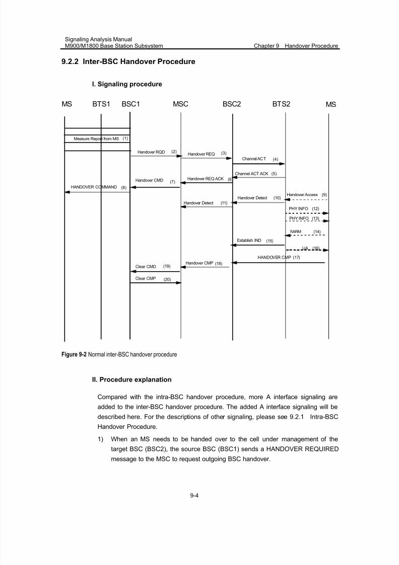
7/30/2019 Signaling Analysis Manual
http://slidepdf.com/reader/full/signaling-analysis-manual 130/290
Signaling Analysis ManualM900/M1800 Base Station Subsystem Chapter 9 Handover Procedure
9-4
9.2.2 Inter-BSC Handover Procedure
I. Signaling procedure
(4)Channel ACT
Channel ACT ACK
BTS1 BSC1MS
SABM
Establish IND
Handover AccessHandover Detect
PHY INFO
PHY INFO
MSC BTS2 MS
Measure Report from MS
HANDOVER COMMAND
Handover REQ
Handover REQ ACKHandover CMD
Handover Detect
Handover CMPClear CMD
Clear CMP
(3)(2)Handover RQD
(1)
(12)
BSC2
(5)
(7)
(8)(9)
(10)
(11)
(6)
(13)
(14)
(15)
HANDOVER CMP (17)
(18)(19)
(20)
(16)UA
Figure 9-2 Normal inter-BSC handover procedure
II. Procedure explanation
Compared with the intra-BSC handover procedure, more A interface signaling are
added to the inter-BSC handover procedure. The added A interface signaling will be
described here. For the descriptions of other signaling, please see 9.2.1 Intra-BSC
Handover Procedure.
1) When an MS needs to be handed over to the cell under management of the
target BSC (BSC2), the source BSC (BSC1) sends a HANDOVER REQUIRED
message to the MSC to request outgoing BSC handover.
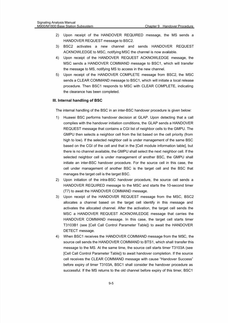
7/30/2019 Signaling Analysis Manual
http://slidepdf.com/reader/full/signaling-analysis-manual 131/290
Signaling Analysis ManualM900/M1800 Base Station Subsystem Chapter 9 Handover Procedure
9-5
2) Upon receipt of the HANDOVER REQUIRED message, the MS sends a
HANDOVER REQUEST message to BSC2.
3) BSC2 activates a new channel and sends HANDOVER REQUEST
ACKNOWLEDGE to MSC, notifying MSC the channel is now available.4) Upon receipt of the HANDOVER REQUEST ACKNOWLEDGE message, the
MSC sends a HANDOVER COMMAND message to BSC1, which will transfer
the message to MS, notifying MS to access in the new channel.
5) Upon receipt of the HANDOVER COMPLETE message from BSC2, the MSC
sends a CLEAR COMMAND message to BSC1, which will initiate a local release
procedure. Then BSC1 responds to MSC with CLEAR COMPLETE, indicating
the clearance has been completed.
III. Internal handling of BSC
The internal handling of the BSC in an inter-BSC handover procedure is given below:
1) Huawei BSC performs handover decision at GLAP. Upon detecting that a call
complies with the handover initiation conditions, the GLAP sends a HANDOVER
REQUEST message that contains a CGI list of neighbor cells to the GMPU. The
GMPU then selects a neighbor cell from the list based on the cell priority (from
high to low). If the selected neighbor cell is under management of the same BSC
based on the CGI of the cell and that in the [Cell module information table], but
there is no channel available, the GMPU shall select the next neighbor cell. If the
selected neighbor cell is under management of another BSC, the GMPU shall
initiate an inter-BSC handover procedure. For the source cell in this case, the
cell under management of another BSC is the target cell and the BSC that
manages the target cell is the target BSC.
2) Upon initiation of the intra-BSC handover procedure, the source cell sends a
HANDOVER REQUIRED message to the MSC and starts the 10-second timer
(T7) to await the HANDOVER COMMAND message.
3) Upon receipt of the HANDOVER REQUEST message from the MSC, BSC2
allocates a channel based on the target cell identify in this message and
activates the allocated channel. After the activation, the target cell sends the
MSC a HANDOVER REQUEST ACKNOWLEDGE message that carries the
HANDOVER COMMAND message. In this case, the target cell starts timer
T3103B1 (see [Cell Call Control Parameter Table]) to await the HANDOVER
DETECT message.
4) When BSC1 receives the HANDOVER COMMAND message from the MSC, the
source cell sends the HANDOVER COMMAND to BTS1, which shall transfer this
message to the MS. At the same time, the source cell starts timer T3103A (see
[Cell Call Control Parameter Table]) to await handover completion. If the source
cell receives the CLEAR COMMAND message with cause “Handover Success”
before expiry of timer T3103A, BSC1 shall consider the handover procedure as
successful. If the MS returns to the old channel before expiry of this timer, BSC1
7/30/2019 Signaling Analysis Manual
http://slidepdf.com/reader/full/signaling-analysis-manual 132/290
Signaling Analysis ManualM900/M1800 Base Station Subsystem Chapter 9 Handover Procedure
9-6
stops this timer and sends a HANDOVER FAILURE message to the MSC. If this
timer times out before reception of the CLEAR COMMAND message, BSC1 shall
consider the call in the handover procedure as dropped and send a CLEAR
REQUEST message to the MSC to release the call.5) Upon receipt of the HANDOVER DETECT message, the target cell stops timer
T3103B1, sends a HANDOVER DETECT message to the MSC and starts timer
T3103B2 to await the HANDOVER COMPLETE message.
6) Upon receipt of the HANDOVER COMPLETE message from the MS, the target
cell stops timer T3103B2 and transfers this message to the MSC, informing the
MSC that an intra-BSC handover has been completed.
7) Upon receiving the CLEAR COMMAND message from the MSC before expiry of
timer T3103A, the source cell locally releases the radio resources and sends
back a MSC CLEAR COMMAND message.
9.2.3 Inter-MSC Handover Procedure
I. Signaling procedure
BTS1 BSC1MS MSC1
Measure Report from MS
(2)Handover RQD
(1)
(5)Channel ACT
BTS2 MS
Handover REQ (4)
BSC2
Channel ACT ACK (6)
Handover Access (13)
Handover REQ ACK (7)
SABM
Establish IND
Handover_Detect
PHY INFO
PHY INFO
Handover Detect
Handover CMP
(15)
(14)
(23)
(16)
(18)
(19)
HANDOVER CMP (21)
(22)
Clear CMD
Clear CMP
(24)
(25)
MSC2
(3)Perform Handover
HANDOVER COMMAND
Handover CMD (11)
(12)
(8)Radio Channel ACK
(9)IAM
(10) ACM
Send End Signal
(17)
(20)UA
Figure 9-3 Normal inter-MSC handover procedure
7/30/2019 Signaling Analysis Manual
http://slidepdf.com/reader/full/signaling-analysis-manual 133/290
Signaling Analysis ManualM900/M1800 Base Station Subsystem Chapter 9 Handover Procedure
9-7
II. Procedure explanation
For the descriptions of this procedure, refer to 9.2.1 Intra-BSC Handover Procedure
and 9.2.2 Inter-BSC Handover Procedure.
Here introduces briefly the messages on the E interface:
1) Perform Handover is the message on MAP layer. It contains the CGI of source
cell and target cell and the required channel type. It informs MSC2 that a
handover will be initiated.
2) RADIO CHANNEL ACK is the message on MAP layer. It contains the information
of the new channel in the target cell and handover number.
3) INITIAL ADDRESS MESSAGE (IAM) is a TUP/ISUP message.
4) ADDRESS COMPLETE MESSAGE (ACM) is a TUP/ISUP message.
5) Send End Signal is a MAP message.
III. Internal handling of BSC
Refer to 9.2.2 III. Internal handling of BSC.
9.3 Abnormal Cases
In case of such exceptions as radio interface message loss, call drop, user hangup,
transmission failure, NSS or even BSS equipment failure, the handover procedure
might be incapable to run normally.
There are many reasons resulting in abnormal handover procedure. Only the
common cases will be described here.
9.3.1 Handover Failure Due to CIC Exception
Suppose the CIC allocated in the Handover REQ received by BSC is marked as
BLOCK, BSC will respond to MSC with HANDOVER FAILURE due to "requested
terrestrial resource unavailable".
9.3.2 Handover Failure Due to MS Access Failure
When a MS accesses the new channel, BTS cannot decode the HANDOVER
ACCESS or HANDOVER COMPLETE message correctly, and the handover will fail.
The MS returns to the old channel and responds with a HANDOVER FAILURE
message.
In the intra-BSC handover, if the BSC has not received the HANDOVER COMPLETE
message on the new channel or HANDOVER FAILURE message on the old channel
at expiry of timer T3103A, it shall consider the call as dropped and send a CLEAR
7/30/2019 Signaling Analysis Manual
http://slidepdf.com/reader/full/signaling-analysis-manual 134/290
Signaling Analysis ManualM900/M1800 Base Station Subsystem Chapter 9 Handover Procedure
9-8
REQUEST message to the MSC on the old channel. Upon receiving the CLEAR
COMMAND message from the MSC, the BSC releases the old channel and notifies
the target cell to release the new channel. If timer T3103B1 or T3103B2 times out, the
target cell shall release the new channel.
In the inter-BSC handover procedure, if BSC1 has not received the HANDOVER
COMPLETE message at expiry of timer T3103B2, it shall send a CLEAR REQUEST
message to the MSC to release the call. If BSC2 has not received the HANDOVER
DETECT or HANDOVER COMPLETE message, it shall send a CLEAR REQUEST
message to the MSC for the same purpose.
9.3.3 Handover Procedure Initiation Failure
In case of handover procedure initiation failure, perform the following steps:1) Check whether the call complies with the handover initiation conditions
2) Check whether there is a CGI list of neighbor cells in the measurement report
3) Check whether there is any channel available for the selected neighbor cell
4) Check whether the data about the selected neighbor cell is correct, for example,
whether the CGI of the neighbor cell is consistent with that in the [Cell module
information table].
5) Log in to the BSC maintenance system. Click [Trace/GSM Trace/GSM Interface
Trace] to display the [Interface Trace] dialog box. Check whether the LAPD has
sent the GMPU a LAPD_GMPU_HO_IND message on the interface between the
GMPU and LAPD. If yes, the call complies with the handover initiation conditions.
If a neighbor cell with correct data already exists but there is still no HANDOVER
COMMAND message on interface Um, check whether the handover procedure
initiation failure is due to no channel available or another reason.
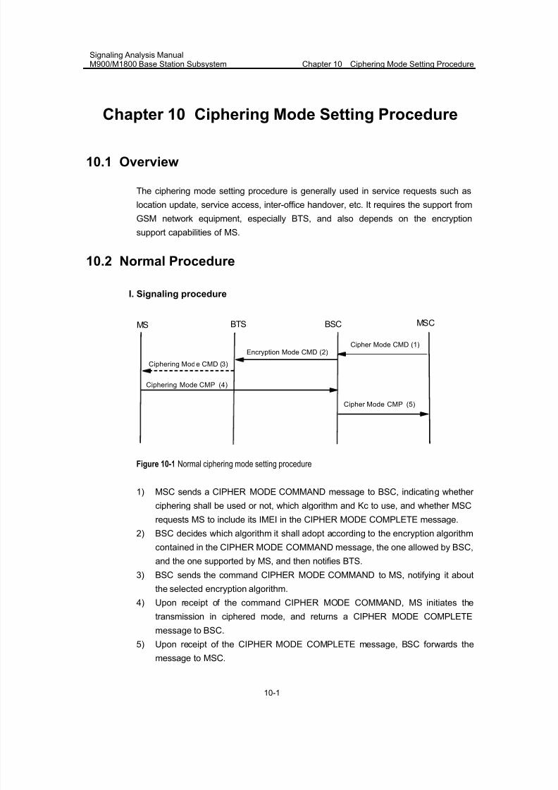
7/30/2019 Signaling Analysis Manual
http://slidepdf.com/reader/full/signaling-analysis-manual 135/290
Signaling Analysis ManualM900/M1800 Base Station Subsystem Chapter 10 Ciphering Mode Setting Procedure
10-1
Chapter 10 Ciphering Mode Setting Procedure
10.1 Overview
The ciphering mode setting procedure is generally used in service requests such as
location update, service access, inter-office handover, etc. It requires the support from
GSM network equipment, especially BTS, and also depends on the encryption
support capabilities of MS.
10.2 Normal Procedure
I. Signaling procedure
BTS BSC MSCMS
Ciphering Mode CMP (4)
Cipher Mode CMD (1)Encryption Mode CMD (2)
Ciphering Mode CMD (3)
Cipher Mode CMP (5)
Figure 10-1 Normal ciphering mode setting procedure
1) MSC sends a CIPHER MODE COMMAND message to BSC, indicating whether
ciphering shall be used or not, which algorithm and Kc to use, and whether MSC
requests MS to include its IMEI in the CIPHER MODE COMPLETE message.
2) BSC decides which algorithm it shall adopt according to the encryption algorithm
contained in the CIPHER MODE COMMAND message, the one allowed by BSC,
and the one supported by MS, and then notifies BTS.
3) BSC sends the command CIPHER MODE COMMAND to MS, notifying it about
the selected encryption algorithm.
4) Upon receipt of the command CIPHER MODE COMMAND, MS initiates the
transmission in ciphered mode, and returns a CIPHER MODE COMPLETE
message to BSC.
5) Upon receipt of the CIPHER MODE COMPLETE message, BSC forwards the
message to MSC.
7/30/2019 Signaling Analysis Manual
http://slidepdf.com/reader/full/signaling-analysis-manual 136/290
Signaling Analysis ManualM900/M1800 Base Station Subsystem Chapter 10 Ciphering Mode Setting Procedure
10-2
II. Procedure explanation
1) Encryption algorithm A5
As specified in the GSM protocols, there are total 8 encryption algorithms, i.e.
A5/0~A5/7. A5/0 indicates "Not ciphered". The ciphering mode setting procedure is
always initiated by the network. The required encryption algorithm is specified in the
encryption IE of the CIPHER MODE COMMAND message.
2) Encryption algorithm selection
When an MS initiates a call request, classmark 2 and classmark 3 may be contained
in the CM SERVICE REQUEST message. In system information, when ECSC is
equal to 1, the MS shall report classmark 3 in the CM SERVICE REQUEST message.
When ECSC is equal to 0, the MS can report classmark 3 only by changing the
classmark or through the classmark updating procedure. Therefore, it is
recommended that ECSC be configured as "1", which contains the information about
the encryption algorithm supported by MS. According to the ciphering data
configuration, MSC delivers CIPHER MODE COMMAND to BSC. BSC
comprehensively considers the encryption algorithm indicated in the command which
is allowed by MSC, the encryption algorithm allowed in BSC data configuration and
the one supported by MS which is indicated in the CM SERV REQ message, and
selects the intersection. Then BSC selects an appropriate algorithm from the
intersection by adopting the method of reverse order. In other words, algorithm
selection priorities decline in the order of A5/7 > A5/6 > A5/5 > A5/4 > A5/4 > A5/3 >
A5/2 > A5/1 > A5/0.
3) Encryption in the handover procedure
In the handover procedure, the HANDOVER REQUEST message contains an
encryption IE, which indicates the to-be-used encryption algorithm and Kc. If either of
the A interfaces of two BSSs is in Phase 1, due to the defect of the ETSI GSM Phase
I protocol (There is no ciphering mode setting IE in the handover command),
inter-BSC handover can be performed normally only when the two BSCs select the
same algorithm (e.g. merely select A5/0, or A5/2). Otherwise, special processing is
required in the destination MSC/BSC, or the originating MSC/BSC (e.g. modify the
inter-BSC handover command). Therefore, in the interconnection of A interfaces under ciphered mode, the user
should learn the difference of data configuration for the encryption function between
different manufacturers. Unsuccessful interconnection has ever occurred during a
to-BSC handover.
10.3 Internal Handling of BSC
The internal handling of the BSC in the ciphering mode setting procedure is given
below:
7/30/2019 Signaling Analysis Manual
http://slidepdf.com/reader/full/signaling-analysis-manual 137/290
Signaling Analysis ManualM900/M1800 Base Station Subsystem Chapter 10 Ciphering Mode Setting Procedure
10-3
1) Upon receipt of the CIPHER MODE COMMAND message from the MSC, the
BSC checks the classmark of the MS and setting for the “Encryption algorithm”
field in the [Cell configuration table].
2) The BSC takes an intersection from the encryption algorithms supported in theCIPHER MODE COMMAND message from the MSC, that defined in the [Cell
configuration table] and that specified in the CM SERVICE REQUEST message
from the MS.
3) The BSC selects an appropriate algorithm from the intersection in the reverse
order of algorithm priority. Note that the normal algorithm priority order (from high
to low) is described as A5/7 > A5/6 > A5/5 > A5/4 > A5/4 > A5/3 > A5/2 > A5/1 >
A5/0. Then the BSC sends a CIPHER MODE COMMAND message to the BTS.
10.4 Abnormal Cases
10.4.1 Ciphering Rejected
BSS shall return a CIPHER MODE REJECT message to MSC, indicating that the
encryption algorithm is not supported, if it does not support the encryption algorithm
specified in the CIPHER MODE COMMAND message.
A CIPHER MODE REJECT message shall also be returned if the MSC requests a
change of ciphering algorithm when BSS ciphering is already active.
10.4.2 MS Not Ciphered
In the following cases, the CIPHER MODE COMMAND messages shall be
considered valid:
z MS in "not ciphered" mode receives a CIPHER MODE COMMAND message,
indicating "start ciphering".
z MS in "not ciphered" mode receives a CIPHER MODE COMMAND message,
indicating "no ciphering".
z MS in "ciphered" mode receives a CIPHER MODE COMMAND message,
indicating "no ciphering".
In other cases, for example, MS in "ciphered" mode receives a CIPHER MODE
COMMAND message, indicating "ciphering", it shall regard the CIPHER MODE
COMMAND messages as erroneous, return an RR Status message with cause
"Protocol error unspecified" and take no further action.
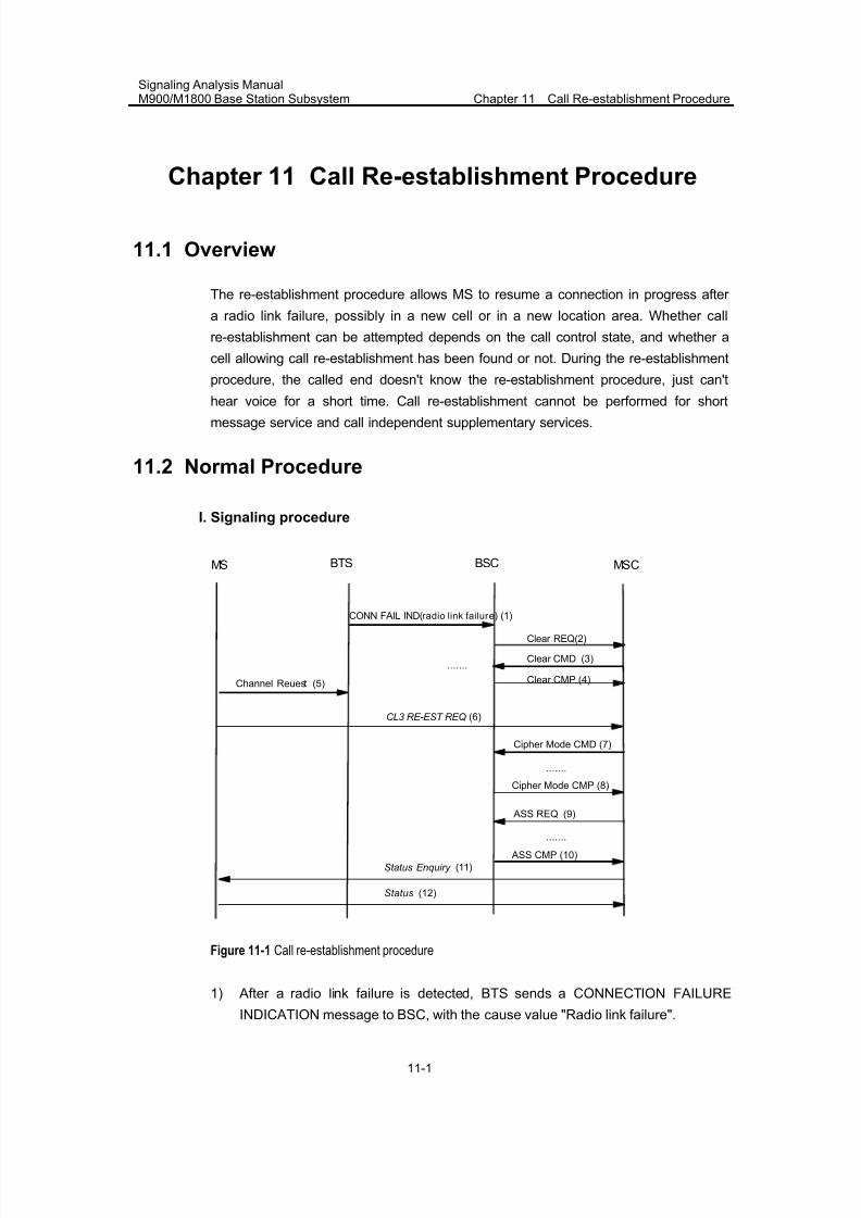
7/30/2019 Signaling Analysis Manual
http://slidepdf.com/reader/full/signaling-analysis-manual 138/290
Signaling Analysis ManualM900/M1800 Base Station Subsystem Chapter 11 Call Re-establishment Procedure
11-1
Chapter 11 Call Re-establishment Procedure
11.1 Overview
The re-establishment procedure allows MS to resume a connection in progress after
a radio link failure, possibly in a new cell or in a new location area. Whether call
re-establishment can be attempted depends on the call control state, and whether a
cell allowing call re-establishment has been found or not. During the re-establishment
procedure, the called end doesn't know the re-establishment procedure, just can't
hear voice for a short time. Call re-establishment cannot be performed for shortmessage service and call independent supplementary services.
11.2 Normal Procedure
I. Signaling procedure
Clear CMD
Clear CMP (4)
CL3 RE-EST REQ (6)
(3)
BTS BSC MSCMS
Clear REQ(2)
CONN FAIL IND(radio link failur e) (1)
Cipher Mode CMD (7)
Cipher Mode CMP (8)
.......
ASS REQ (9)
ASS CMP (10)
.......
Status (12)
Status Enquiry (11)
.......
Channel Reuest (5)
Figure 11-1 Call re-establishment procedure
1) After a radio link failure is detected, BTS sends a CONNECTION FAILURE
INDICATION message to BSC, with the cause value "Radio link failure".
7/30/2019 Signaling Analysis Manual
http://slidepdf.com/reader/full/signaling-analysis-manual 139/290
Signaling Analysis ManualM900/M1800 Base Station Subsystem Chapter 11 Call Re-establishment Procedure
11-2
2) BSC sends a CLEAR REQUEST message to MSC, which contains the cause for
the abnormal release.
3) Upon receipt of the message, MSC sends a CLEAR COMMAND to BSC,
requesting the release of radio resources.4) BSC initiates the release procedure, releases the physical channel resources on
Um interface, and returns a CLEAR COMPLETE message to MSC.
5) MS sends a CHANNEL REQUEST message (with the cause value of "Call
re-establishment") to BTS, and initiates the immediate assignment procedure (to
seize signaling channels).
6) MS initiates the call re-establishment procedure, by sending a CM
RE-ESTABLISHMENT REQUEST message to MSC. The MM sublayer of MS
starts timer T3230, gives an indication to all CM entities that are being
re-established, and remains in the MM sublayer state "WAIT FOR
REESTABLISH". The CM RE-ESTABLISHMENT REQUEST message contains
IMSI/TMSI, classmark 2 and CKSM.
7) MSC initiates the ciphering mode setting procedure by delivering a CIPHER
MODE COMMAND message to MS. For the specific signaling processing
procedure, please refer to Chapter 9 Ciphering Mode Setting Procedure. After
the ciphering mode setting procedure is completed, or after MS receives a CM
SERVICE ACCEPT message, timer T3230 is stopped, and MS enters the MM
sublayer state "MM CONNECTION ACTIVE".
8) BSC returns a CIPHER MODE COMPLETE message to MSC.
9) MSC sends an ASSIGNMENT REQUEST message to BSC, and initiates the
signaling processing procedure. Refer to "Assignment Procedure" of Chapter 6
Mobile Originating Call Establishment Procedure.
10) BSC returns an ASSIGNMENT COMPLETE message to MSC.
11) MSC initiates status query by sending a STATUS ENQUIRY message to MS, to
check whether the call state or MM substate is consistent.
12) MS sends a STATUS message to MSC, reporting its calling status or MM
substate.
II. Procedure explanation
1) In Figure 11-1, 1~4 are to release radio channel resources, are the same with
normal release procedure.
2) 5~6 refer to the immediate assignment procedure, i.e. signaling channel seizure
procedure.
3) 7~8 refer to the ciphering mode setting procedure.
4) 9~10 refer to the assignment procedure.
5) Initiating of the call re-establishment procedure
If a cell is required to support call re-establishment, the call re-establishment
parameter of the cell must be set to "Allowed", and the cell cannot be in barred state.
7/30/2019 Signaling Analysis Manual
http://slidepdf.com/reader/full/signaling-analysis-manual 140/290
Signaling Analysis ManualM900/M1800 Base Station Subsystem Chapter 11 Call Re-establishment Procedure
11-3
MS shall send a call re-establishment request in the selected cell (possibly the
previous cell, or a new cell), when it first detects a radio link failure. The previous
channel resources shall be released by BSC after the timer on BTS side expires.
After detecting the radio link failure, BTS shall send a CONNECTION FAILURE
message to BSC, indicating that radio link failure has occurred. Accordingly, BSC
shall release the corresponding radio resources, and await MS's initiating call
re-establishment.
6) MS's mode in the call re-establishment procedure
During a call re-establishment attempt, MS does not return to idle mode. Therefore,
no location updating shall be performed even if MS is not updated in the location area
of the selected cell.
III. Internal handling of BSC
None.
11.3 Abnormal Cases
11.3.1 CM Service Rejected
After receipt of a CM RE-ESTABLISHMENT REQUEST, if the RR sublayer sends an
indication that the ciphering mode setting procedure is completed, or if a CMSERVICE ACCEPT message is received, MS shall treat the indication or receipt as a
service acceptance indication, and re-enter the MM sublayer state "MM
CONNECTION ACTIVE".
If the network cannot associate the re-establishment request with any existing call for
the MS, a CM SERVICE REJECT message shall be returned with cause "Call cannot
be identified".
If call re-establishment cannot be performed for other reasons, a CM SERVICE
REJECT message shall be returned. The appropriate reject cause value may be
""IMSI unknown in VLR", "illegal ME", "network failure", "congestion", "service option
not supported", or "service option temporarily out of order".
Whatever the reject cause may be, upon receipt of the CM SERVICE REJECT
message, the MS shall stop timer T3230 and release all MM connections and
relevant RR connections.
7/30/2019 Signaling Analysis Manual
http://slidepdf.com/reader/full/signaling-analysis-manual 141/290
Signaling Analysis ManualM900/M1800 Base Station Subsystem Chapter 11 Call Re-establishment Procedure
11-4
11.3.2 Re-establishment Not Allowed or Re-establishment Failure
When MM connection is established, the MM layer may send an indication to the CC
layer. If the MM layer is disconnected, the connection may be re-established throughCC request.
If the re-establishment is not allowed, and the call is initiated within the establishment
or clearing period, the CC layer shall release MM connections.
If re-establishment is unsuccessful, MM connections shall be released, and a release
indication shall be sent to the CC layer..
11.3.3 RR Connection Failure
If random access failure or RR CONNECTION FAILURE is detected by MS, MS shall
stop timer T3230, abort the call re-establishment procedure and release all MM
connections.
If RR CONNECTION FAILURE is detected by MSC, MSC shall abort the call
re-establishment procedure and release all MM connections.
7/30/2019 Signaling Analysis Manual
http://slidepdf.com/reader/full/signaling-analysis-manual 142/290
Signaling Analysis ManualM900/M1800 Base Station Subsystem Chapter 12 Directed Retry Procedure
12-1
Chapter 12 Directed Retry Procedure
12.1 Overview
A directed retry procedure is actually a type of special handover procedure. In the
assignment procedure, if there is no available radio resource in the new cell, the MS
shall be handed over to the neighbor cell. It is a type of handover from a signaling
channel to a traffic channel.
12.2 Normal Procedure
Based on the BSC and MSC that manage the serving cell and target cell, a directed
retry handover procedure can be classified into three types: directed retry intra-BSC
handover procedure, directed retry inter-BSC handover procedure and directed retry
inter-MSC handover procedure.
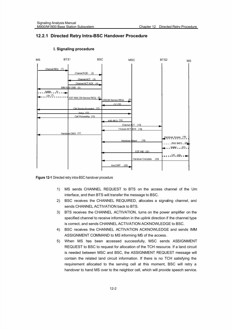
7/30/2019 Signaling Analysis Manual
http://slidepdf.com/reader/full/signaling-analysis-manual 143/290
Signaling Analysis ManualM900/M1800 Base Station Subsystem Chapter 12 Directed Retry Procedure
12-2
12.2.1 Directed Retry Intra-BSC Handover Procedure
I. Signaling procedure
BTS1 BSCMSMS BTS2MSC
Handover CMD
Channel ACT ACK (16)
(17)
Handover Access (18)
SABM (21)
EST IND (22)
PHY INFO (20)Handover Detect (19)
Handover Complete (24)
Channel ACT
Channel ACT ACK
IMM ASS CMD
Channel REQ
SABM
EST IND( CM Service REQ)CR(CM Service REQ)
CC
Setup
Call Proceeding
ASS REQ
CM Service Accepted
UA
(1)
(3)
(4)
(5)
6)
(7)(8)
(9)
(10)
(11)
(12)
(13)
(14)
Channel ACT (15)
Ass CMP (25)
(23)UA
Channel RQD (2)
Figure 12-1 Directed retry intra-BSC handover procedure
1) MS sends CHANNEL REQUEST to BTS on the access channel of the Um
interface, and then BTS will transfer the message to BSC.
2) BSC receives the CHANNEL REQUIRED, allocates a signaling channel, and
sends CHANNEL ACTIVATION back to BTS.
3) BTS receives the CHANNEL ACTIVATION, turns on the power amplifier on the
specified channel to receive information in the uplink direction if the channel typeis correct, and sends CHANNEL ACTIVATION ACKNOWLEDGE to BSC.
4) BSC receives the CHANNEL ACTIVATION ACKNOWLEDGE and sends IMM
ASSIGNMENT COMMAND to MS informing MS of the access.
5) When MS has been accessed successfully, MSC sends ASSIGNMENT
REQUEST to BSC to request for allocation of the TCH resource. If a land circuit
is needed between MSC and BSC, the ASSIGNMENT REQUEST message will
contain the related land circuit information. If there is no TCH satisfying the
requirement allocated to the serving cell at this moment, BSC will retry a
handover to hand MS over to the neighbor cell, which will provide speech service.
7/30/2019 Signaling Analysis Manual
http://slidepdf.com/reader/full/signaling-analysis-manual 144/290
Signaling Analysis ManualM900/M1800 Base Station Subsystem Chapter 12 Directed Retry Procedure
12-3
If the target cell is in the same BSC with the serving cell, this handover is a
directed retry intra-BSC handover.
II. Procedure explanation
1) (1) ~ (8) in Figure 12-1 illustrates a random access and immediate assignment
procedure, in which BSS allocates signaling channel to MS.
2) (14) ~ (24) in Figure 12-1 illustrates a TCH directed retry procedure, in which
BSS allocates such resources as speech channel and A interface circuit for MS
through handover.
III. Internal handling of BSC
Upon receiving the ASSIGNMENT REQUEST message from the MSC, if there is no
TCH available in the cell where the MS is located and if the “Direct retry” field in the
[Cell call control table] is set to “Yes”, the BSC shall initiate a directed retry handover
procedure.
The GMPU in the BSC first start the 8-second timer to await the HANDOVER
INDICATION message from the LAPD and then initiate a forced handover procedure,
as described below:
1) The GMPU sends a “Forced HANDOVER COMMAND” to the LAPD to initiate a
forced handover procedure.
2) The LAPD sends a HANDOVER INDICATION message that contains a CGI list
of the neighbor cells to the BSC. Upon receipt of this message, the BSC stopsthe 8-second timer.
3) The BSC selects a neighbor cell from the CGI list based on the cell priority (from
high to low). If the selected neighbor cell is under management of the same BSC
but there is no channel available, the BSC shall select the next neighbor cell. If
the selected neighbor cell is under management of another BSC based on the
CGI of the cell and that in the [Cell module information table], the BSC shall
initiate a directed retry inter-BSC handover procedure (see the next section). If
the selected neighbor cell with the highest priority is under management of the
same BSC based on the CGI of the cell and that in the [Cell module information
table] and there is a channel available, the BSC shall initiate a directed retry
intra-BSC handover procedure. In this case, the selected neighbor cell is the
target cell for the directed retry handover. The source cell where the call is
initiated sends an “Internal HANDOVER REQUEST” to the target cell and starts
the 2-second timer to await the handover preparation completion.
4) Upon receipt of the “Internal HANDOVER REQUEST”, the target cell allocates a
channel and notifies the target BTS (BTS2) to activate the allocated channel.
5) Upon completion of channel activation, the target cell sends a CHANNEL
ACTIVATION ACKNOWLEDGE message to the source cell, informing the
7/30/2019 Signaling Analysis Manual
http://slidepdf.com/reader/full/signaling-analysis-manual 145/290
Signaling Analysis ManualM900/M1800 Base Station Subsystem Chapter 12 Directed Retry Procedure
12-4
source cell that the channel is available. Then it starts timer T3103B1 (see [Cell
Call Control Parameter Table]) to await the HANDOVER DETECT message.
6) Upon receipt of the CHANNEL ACTIVATION ACKNOWLEDGE message, the
source cell sends a HANDOVER COMMAND message to BTS1, stops the2-second timer and starts timer T3103A (see [Cell Call Control Parameter Table].
7) Upon receipt of the HANDOVER DETECT message, the target cell stops timer
T3103B1 and starts timer T3103B2 (see [Cell Call Control Parameter Table]) to
await the HANDOVER COMPLETE message.
8) Upon receipt of the HANDOVER COMPLETE message from the MS, the target
cell stops timer T3103B2 and notifies the relevant modules such as AIE and AIR
to update the RR connection number. At the same time, it sends an “Internal
Handover Success” message to the source cell.
9) The target cell sends the MSC an ASSIGNMENT COMPLETE message that
contains target cell information, informing the MSC that the assignment has been
completed.
10) Upon receipt of the “Internal Handover Success” message, the source cell
initiates a local release procedure to release the relevant resources.
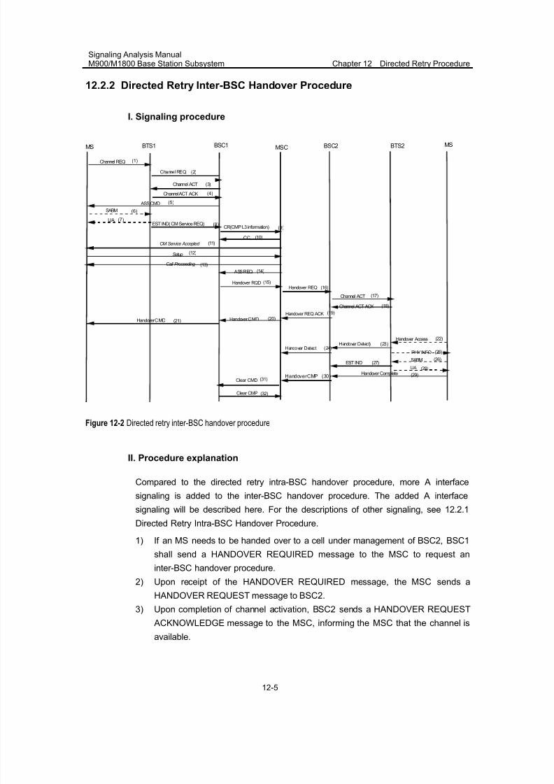
7/30/2019 Signaling Analysis Manual
http://slidepdf.com/reader/full/signaling-analysis-manual 146/290
Signaling Analysis ManualM900/M1800 Base Station Subsystem Chapter 12 Directed Retry Procedure
12-5
12.2.2 Directed Retry Inter-BSC Handover Procedure
I. Signaling procedure
Clear CMD
Clear CMP
(31)
(32)
BTS1 BSC2 MSMS BTS2MSC
Handover CMD (21)
Channel ACT
Channel ACT ACK
ASS CMD
Channel REQ
SABM
EST IND( CM Service REQ)CR(CMP L3 information)
CC
Setup
Call Proceeding
ASS REQ
CM Service Accepted
UA
(1)
(3)
(4)
(5)
(6)
(7)(8)
(9)
(10)
(11)
(12)
(13)
(14)
Channel ACT ACK (18)
EST IND (27)
Handover Access (22)
SABM (26)
PHY INFO (25)
Handover Detect) (23)
Handover Complete (29)
Channel ACT (17)
Handover REQ
Handover REQ ACKHandover CMD
(16)(15)Handover RQD
(20)
Handover Detect (24)
(19)
BSC1
HandoverCMP (30)
(28)UA
Channel REQ (2)
Figure 12-2 Directed retry inter-BSC handover procedure
II. Procedure explanation
Compared to the directed retry intra-BSC handover procedure, more A interface
signaling is added to the inter-BSC handover procedure. The added A interface
signaling will be described here. For the descriptions of other signaling, see 12.2.1
Directed Retry Intra-BSC Handover Procedure.
1) If an MS needs to be handed over to a cell under management of BSC2, BSC1
shall send a HANDOVER REQUIRED message to the MSC to request an
inter-BSC handover procedure.
2) Upon receipt of the HANDOVER REQUIRED message, the MSC sends a
HANDOVER REQUEST message to BSC2.
3) Upon completion of channel activation, BSC2 sends a HANDOVER REQUEST
ACKNOWLEDGE message to the MSC, informing the MSC that the channel is
available.
7/30/2019 Signaling Analysis Manual
http://slidepdf.com/reader/full/signaling-analysis-manual 147/290
Signaling Analysis ManualM900/M1800 Base Station Subsystem Chapter 12 Directed Retry Procedure
12-6
4) Upon receipt of the HANDOVER REQUEST ACKNOWLEDGE message, the
MSC sends a HANDOVER COMMAND message to BSC1. BSC1 then transfers
this message to the MS, notifying the MS to access in the new channel.
5) Upon receipt of the HANDOVER COMPLETE message, the MSC sends aCLEAR COMMAND message to BSC1. Upon receiving the CLEAR COMMAND
message BSC1 initiates a local release procedure to release the old channel and
sends back a CLEAR COMPLETE message to the MSC.
III. Internal handling of BSC
Upon receiving the ASSIGNMENT REQUEST message from the MSC, if there is no
TCH available in the cell where the MS is located and if the “Direct retry” field in the
[Cell Call Control Table] is set to “Yes”, the BSC shall initiate a directed retry handover
procedure.
The GMPU in the BSC first starts the 8-second timer to await the HANDOVER
INDICATION message from the LAPD and then initiates a forced handover procedure,
as described below:
1) The GMPU sends a “Forced HANDOVER COMMAND” to the LAPD to initiate a
forced handover procedure.
2) The LAPD sends a HANDOVER INDICATION message that contains a CGI list
of the neighbor cells to the BSC. Upon receipt of this message, the BSC stops
the 8-second timer.
3) The BSC selects a neighbor cell from the CGI list based on the cell priority (fromhigh to low). If the selected neighbor cell is under management of the same BSC
but there is no channel available, the BSC shall select the next neighbor cell. If
the selected neighbor cell is under management of a different BSC based on the
CGI of the cell and that in the [Cell module information table], the BSC shall
initiate a directed retry inter-BSC handover procedure. Upon initiation of this
procedure, the source cell sends a HANDOVER REQUIRED message to the
MSC and starts the 10-second timer (T17) to await the HANDOVER COMMAND
message.
4) Upon receipt of the HANDOVER REQUEST message from the MSC, BSC2
allocates a channel to the target cell based on the target cell identity in this
message and activates the allocated channel. When the channel has been
activated, the source cell sends the MSC a HANDOVER REQUEST
ACKNOWLEDGE message that contains the HANDOVER COMMAND message.
In this case, the target cell starts timer T3103B1 (see [Cell Call Control
Parameter Table] to await the HANDOVER DETECT message.
5) When BSC1 receives the HANDOVER COMMAND message from the MSC, the
source cell sends the HANDOVER COMMAND message BTS1, which will
transfer it to the MS. At the same time, the source cell starts timer T3103A.
BSC1 considers the handover procedure as successful upon receiving the
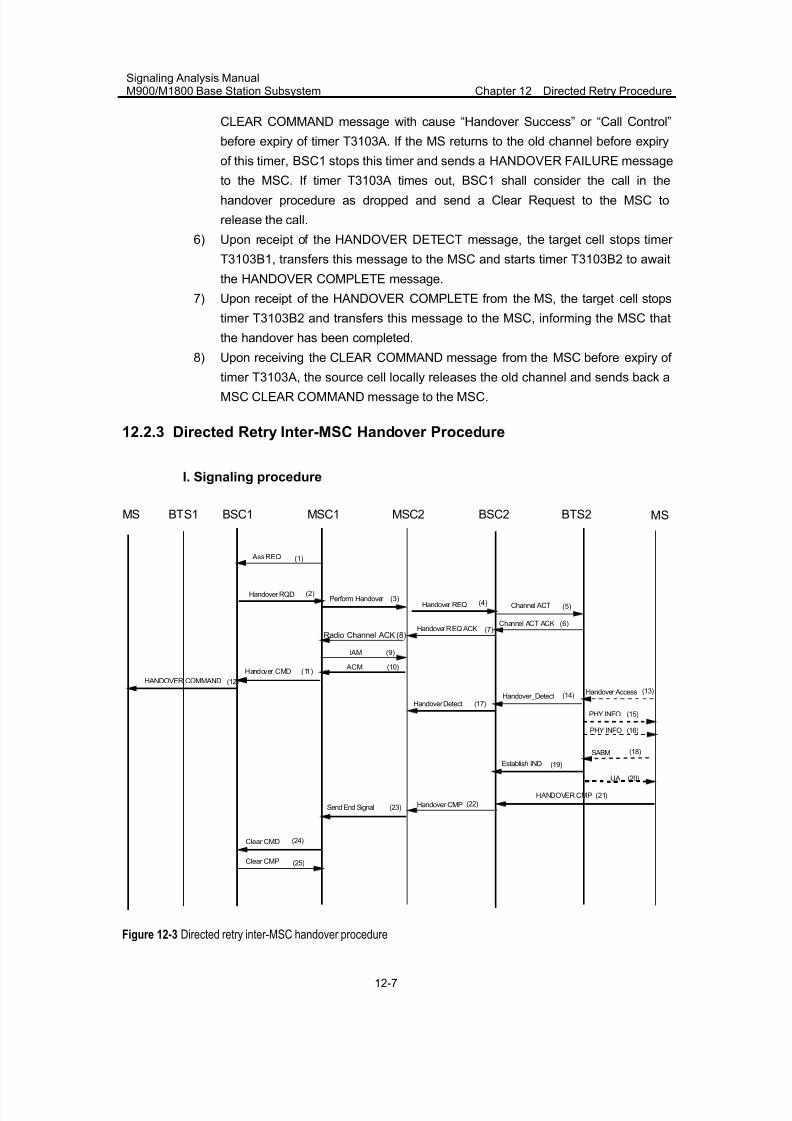
7/30/2019 Signaling Analysis Manual
http://slidepdf.com/reader/full/signaling-analysis-manual 148/290
Signaling Analysis ManualM900/M1800 Base Station Subsystem Chapter 12 Directed Retry Procedure
12-7
CLEAR COMMAND message with cause “Handover Success” or “Call Control”
before expiry of timer T3103A. If the MS returns to the old channel before expiry
of this timer, BSC1 stops this timer and sends a HANDOVER FAILURE message
to the MSC. If timer T3103A times out, BSC1 shall consider the call in thehandover procedure as dropped and send a Clear Request to the MSC to
release the call.
6) Upon receipt of the HANDOVER DETECT message, the target cell stops timer
T3103B1, transfers this message to the MSC and starts timer T3103B2 to await
the HANDOVER COMPLETE message.
7) Upon receipt of the HANDOVER COMPLETE from the MS, the target cell stops
timer T3103B2 and transfers this message to the MSC, informing the MSC that
the handover has been completed.
8) Upon receiving the CLEAR COMMAND message from the MSC before expiry of
timer T3103A, the source cell locally releases the old channel and sends back a
MSC CLEAR COMMAND message to the MSC.
12.2.3 Directed Retry Inter-MSC Handover Procedure
I. Signaling procedure
BTS1 BSC1MS MSC1
(2)Handover RQD
(5)Channel ACT
BTS2 MS
Handover REQ (4)
BSC2
Channel ACT ACK (6)
Handover Access (13)
Handover REQ ACK (7)
SABM
Establish IND
Handover_Detect
PHY INFO
PHY INFO
Handover Detect
Handover CMP
(15)
(14)
(23)
(16)
(18)
(19)
HANDOVER CMP (21)(22)
Clear CMD
Clear CMP
(24)
(25)
MSC2
(3)Perform Handover
HANDOVER COMMAND
Handover CMD (11)
(12)
(8)Radio Channel ACK
(9)IAM
(10) ACM
Send End Signal
(17)
Ass REQ(1)
(20)UA
Figure 12-3 Directed retry inter-MSC handover procedure
7/30/2019 Signaling Analysis Manual
http://slidepdf.com/reader/full/signaling-analysis-manual 149/290
Signaling Analysis ManualM900/M1800 Base Station Subsystem Chapter 12 Directed Retry Procedure
12-8
II. Procedure explanation
Refer to 12.2.2 Directed Retry Inter-BSC Handover Procedure.
12.3 Abnormal Cases
The directed retry handover procedure might be incapable to work normally due to
radio interface message loss, call interruption, user on-hook, transmission failure or
NSS/BSS operation failure.
There are many causes for the abnormal cases. Only the typical cases will be
described here.
I. Directed retry inter-BSC handover failure due to no available channel in the
target cell
When there is no available channel in the target cell, this cell will respond with a
HANDOVER FAILURE message and the source cell will respond to MSC with
ASSIGNMENT FAILURE.
II. Directed retry intra-BSC handover failure due to CHANNEL ACTIVATION
failure
In case of CHANNEL ACTIVATION failure in the target cell, BSC responds to MSC
with ASSIGNMENT FAILURE.

7/30/2019 Signaling Analysis Manual
http://slidepdf.com/reader/full/signaling-analysis-manual 150/290
Signaling Analysis ManualM900/M1800 Base Station Subsystem Chapter 13 Short Message Procedure
13-1
Chapter 13 Short Message Procedure
13.1 Overview
Short messages can be transmitted either on SDCCH or SACCH. A short message
procedure can be classified into short message calling procedure and called
procedure.
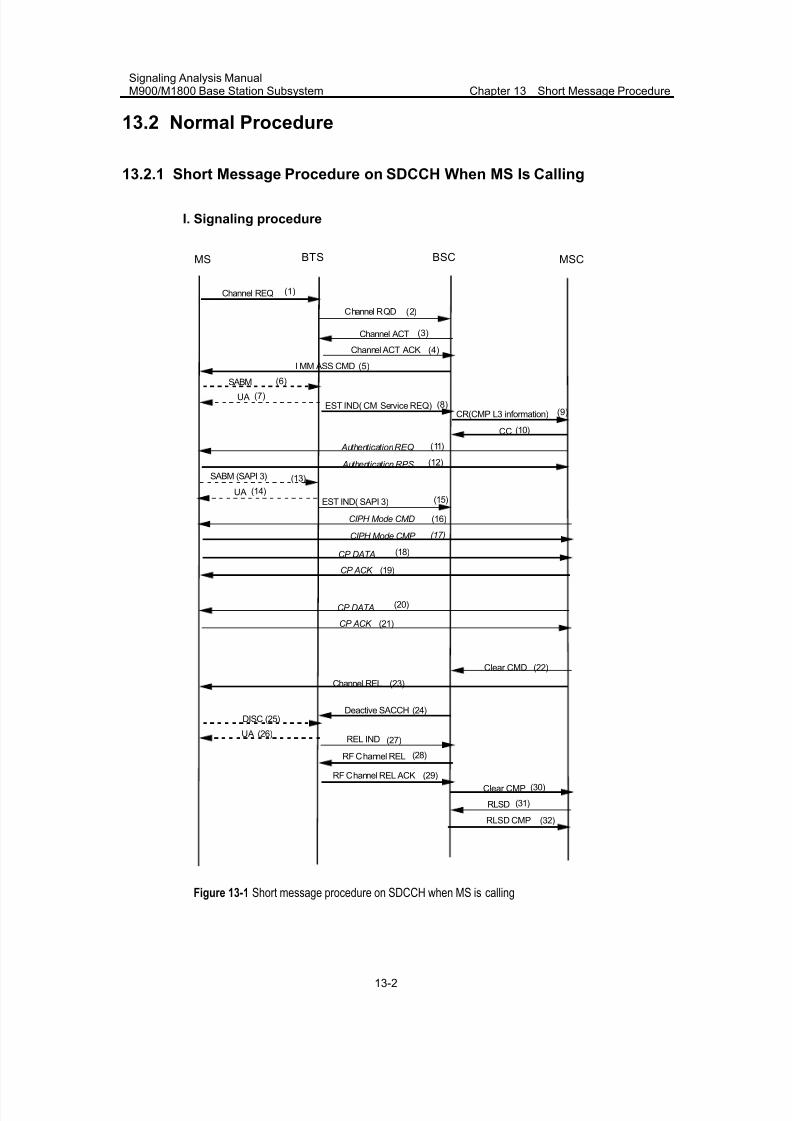
7/30/2019 Signaling Analysis Manual
http://slidepdf.com/reader/full/signaling-analysis-manual 151/290
Signaling Analysis ManualM900/M1800 Base Station Subsystem Chapter 13 Short Message Procedure
13-2
13.2 Normal Procedure
13.2.1 Short Message Procedure on SDCCH When MS Is Calling
I. Signaling procedure
BTS BSC MSCMS
Channel ACT
Channel ACT ACK
I MM ASS CMD
Channel REQ
CC
Authentication RPS
Authentication REQ
(1)
(3)
(4)
(5)
SABM
EST IND( CM Service REQ)CR(CMP L3 information)
UA
(6)
(7)(8)
(9)
(10)
(11)
(12)
Clear CMD
Clear CMP
Channel REL
REL IND
Deactive SACCH
RF Channel REL
RF Channel REL ACK
DISC
UA
RLSD
RLSD CMP
CIPH Mode CMD (16)
CIPH Mode CMP (17)
CP ACK
CP DATA
(19)
(18)
(22)
(23)
(25)
(26)
(24)
(27)
(28)
(29)
(30)
(31)
(32)
CP ACK
CP DATA
(21)
(20)
SABM (SAPI 3)
EST IND( SAPI 3)UA
(13)
(14)(15)
Channel RQD (2)
Figure 13-1 Short message procedure on SDCCH when MS is calling
7/30/2019 Signaling Analysis Manual
http://slidepdf.com/reader/full/signaling-analysis-manual 152/290
Signaling Analysis ManualM900/M1800 Base Station Subsystem Chapter 13 Short Message Procedure
13-3
II. Procedure explanation
1) (1) ~ (8) in Figure 13-1 illustrates a random access and immediate assignment
procedure, in which BSS allocates signaling channel to MS.
2) (15) ~ (21) is a short message transmission procedure.
MS sends SABM again, notifying the network side that this user needs short message
service (SMS). Then, BSC provides a transparent-transmission channel for MS to
exchange short message information with MSC. In this procedure, the MSCs of some
manufacturers are capable to send ASS REQ to BSC, requesting it to assign channel
for short message transmission. The time for sending ASS REQ is the same as that
for a common call. BSC can provide SMS either by allocating other channels or by
using the original SDCCH.
Point to Point short message protocol is divided into connection management layer
(CM), relay layer (RL), transport layer (TL) and application layer (AL).
CP_DATA and CP_ACK are the messages on CM layer, CP_DATA is used to transmit
the content of RL and AL message and CP_ACK is the acknowledgement message of
CP_DATA.
3) (22) ~ (35) is a release procedure.
MSC initiates a release procedure upon the completion of short message
transmission.
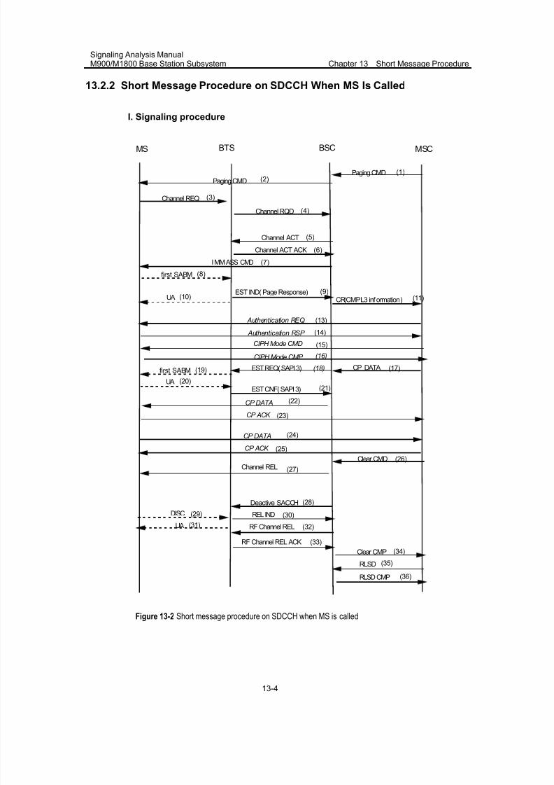
7/30/2019 Signaling Analysis Manual
http://slidepdf.com/reader/full/signaling-analysis-manual 153/290
Signaling Analysis ManualM900/M1800 Base Station Subsystem Chapter 13 Short Message Procedure
13-4
13.2.2 Short Message Procedure on SDCCH When MS Is Called
I. Signaling procedure
BTS BSC MSCMS
Channel ACT
Channel ACT ACK
I MM ASS CMD
Channel REQ
CP_DATA
Authentication RSP
Authentication REQ
(3)
(5)
(6)
(7)
first SABM
EST IND( Page Response)CR(CMP L3 inf ormation)UA
(8)
(10)(9)
(11)
(17)
(13)
(14)
Clear CMD
Clear CMP
Channel REL
REL IND
Deactive SACCH
RF Channel REL
RF Channel REL ACK
DISC
UA
RLSD
RLSD CMP
CIPH Mode CMD (15)
CIPH Mode CMP (16)
CP ACK
CP DATA
(23)
(22)
(26)
(27)
(29)
(31)
(28)
(30)
(32)
(33)
(34)
(35)
(36)
CP ACK
CP DATA
(25)
(24)
Paging CMD
Paging CMD
first SABM
EST CNF( SAPI 3)UA
(19)
(20)(21)
EST REQ( SAPI 3)
(1)(2)
(18)
Channel RQD (4)
Figure 13-2 Short message procedure on SDCCH when MS is called
7/30/2019 Signaling Analysis Manual
http://slidepdf.com/reader/full/signaling-analysis-manual 154/290
Signaling Analysis ManualM900/M1800 Base Station Subsystem Chapter 13 Short Message Procedure
13-5
II. Procedure explanation
1) (1) ~ (10) is a paging response and immediate assignment procedure.
MSC sends Paging CMD to page the called subscriber. MS requests for SDCCH, and
responds with Paging Response.
2) (17) ~ (25) is a short message setup and transmission procedure.
For the short message procedure when MS is called, BSC sends EST REQ to MS to
establish short message connection. When EST CNF is received from MS, the
connection is successfully established. BSC transparently transmits the short
message till the end of the transmission. (13), (14), (15) and (16) are optional
signaling procedures.
3) (26) ~ (36) is a release procedure.
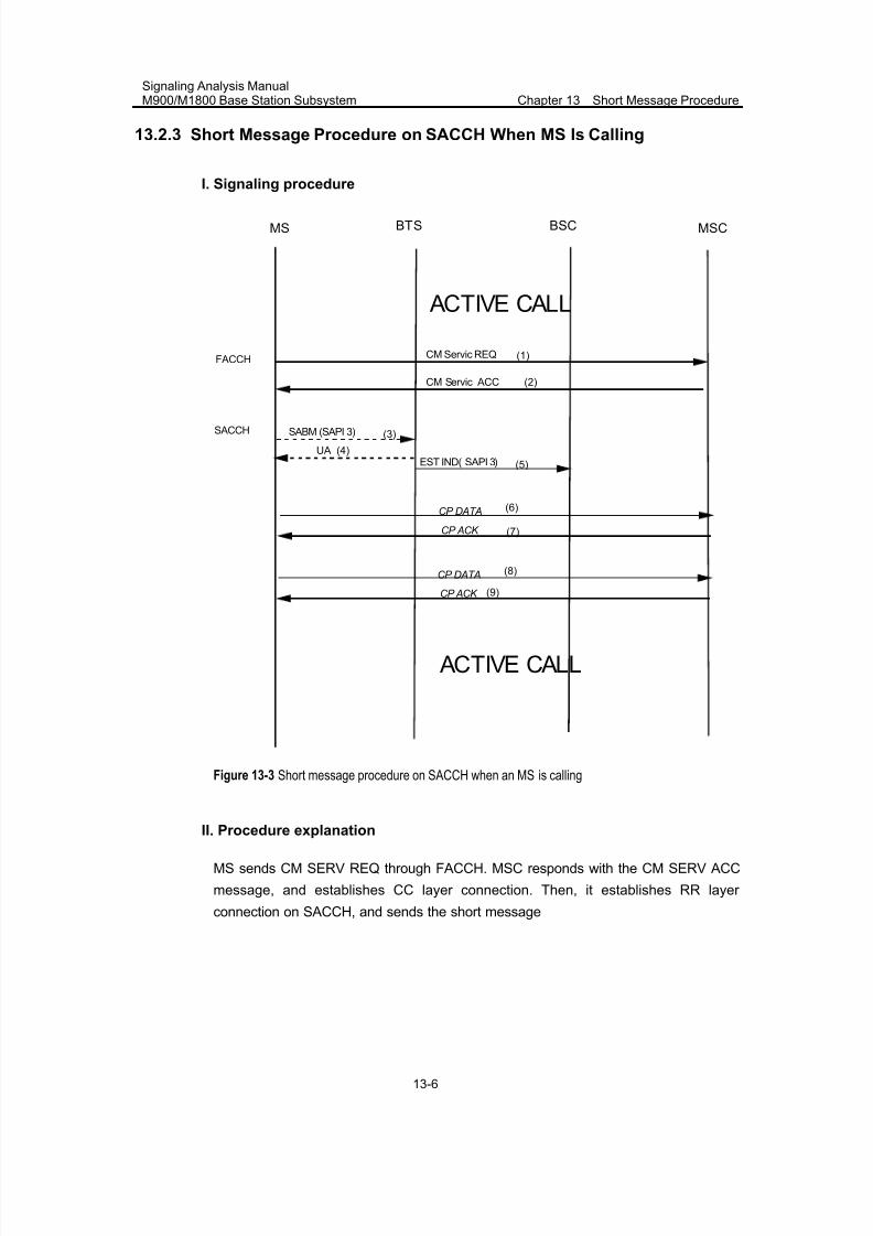
7/30/2019 Signaling Analysis Manual
http://slidepdf.com/reader/full/signaling-analysis-manual 155/290
Signaling Analysis ManualM900/M1800 Base Station Subsystem Chapter 13 Short Message Procedure
13-6
13.2.3 Short Message Procedure on SACCH When MS Is Calling
I. Signaling procedure
BTS BSC MSCMS
CM Servic ACC
CM Servic REQ (1)
(2)
CP ACK
CP DATA
(7)
(6)
CP ACK
CP DATA
(9)
(8)
SABM (SAPI 3)
EST IND( SAPI 3)UA
(3)
(4)
(5)
FACCH
SACCH
ACTIVE CALL
ACTIVE CALL
Figure 13-3 Short message procedure on SACCH when an MS is calling
II. Procedure explanation
MS sends CM SERV REQ through FACCH. MSC responds with the CM SERV ACC
message, and establishes CC layer connection. Then, it establishes RR layer
connection on SACCH, and sends the short message
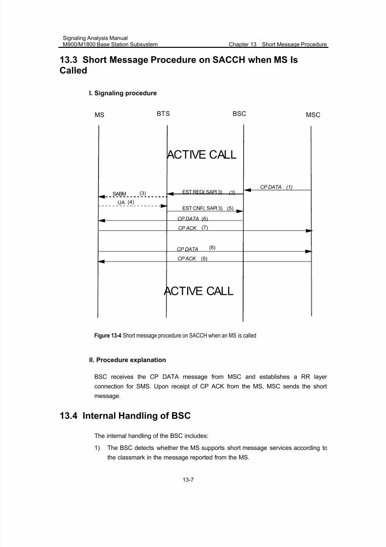
7/30/2019 Signaling Analysis Manual
http://slidepdf.com/reader/full/signaling-analysis-manual 156/290
Signaling Analysis ManualM900/M1800 Base Station Subsystem Chapter 13 Short Message Procedure
13-7
13.3 Short Message Procedure on SACCH when MS IsCalled
I. Signaling procedure
BTS BSC MSCMS
CP ACK
CP DATA
(7)
(6)
CP ACK
CP DATA
(9)
(8)
SABM
EST CNF( SAPI 3)UA
(3)
(4)
(5)
EST REQ( SAPI 3) (2)CP DATA
ACTIVE CALL
ACTIVE CALL
(1)
Figure 13-4 Short message procedure on SACCH when an MS is called
II. Procedure explanation
BSC receives the CP DATA message from MSC and establishes a RR layer
connection for SMS. Upon receipt of CP ACK from the MS, MSC sends the short
message.
13.4 Internal Handling of BSC
The internal handling of the BSC includes:
1) The BSC detects whether the MS supports short message services according to
the classmark in the message reported from the MS.
7/30/2019 Signaling Analysis Manual
http://slidepdf.com/reader/full/signaling-analysis-manual 157/290
Signaling Analysis ManualM900/M1800 Base Station Subsystem Chapter 13 Short Message Procedure
13-8
2) Upon receipt of the short message from the MS, the BSC checks the [Cell Call
Control Table] for the configuration of the “Short message uplink disabled” field.
If the field is set to yes, the short message cannot be sent.
3) Upon receipt of the short message from the MSC, the BSC checks the [Cell CallControl Table] for the configuration of the “Short message downlink disabled”
field. If the field is set to yes, the short message cannot be sent.
13.5 Abnormal Cases
In case of short message procedure failure, perform the following:
1) Check whether the MS supports short message services
2) Check the [Cell Call Control Table] for the configuration of the “Short message
uplink disabled” or “Short message uplink disabled” field. If a field is set to “Yes”,
modify the value to “No”.
3) Perform signaling tracing to check the equipment on the network side, for
example, the short message service center (SMSC). In case of short message
transmission failure, the MS receives CP DATA and responds to the MSC with
CP NACK, informing the MSC of short message transmission failure.
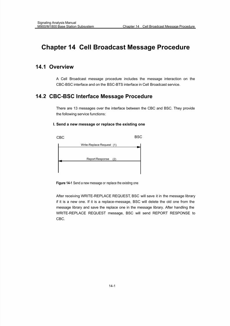
7/30/2019 Signaling Analysis Manual
http://slidepdf.com/reader/full/signaling-analysis-manual 158/290
Signaling Analysis ManualM900/M1800 Base Station Subsystem Chapter 14 Cell Broadcast Message Procedure
14-1
Chapter 14 Cell Broadcast Message Procedure
14.1 Overview
A Cell Broadcast message procedure includes the message interaction on the
CBC-BSC interface and on the BSC-BTS interface in Cell Broadcast service.
14.2 CBC-BSC Interface Message Procedure
There are 13 messages over the interface between the CBC and BSC. They providethe following service functions:
I. Send a new message or replace the existing one
BSCCBC
Write-Replace Request (1)
Report Response (2)
Figure 14-1 Send a new message or replace the existing one
After receiving WRITE-REPLACE REQUEST, BSC will save it in the message library
if it is a new one. If it is a replace-message, BSC will delete the old one from the
message library and save the replace one in the message library. After handling the
WRITE-REPLACE REQUEST message, BSC will send REPORT RESPONSE to
CBC.
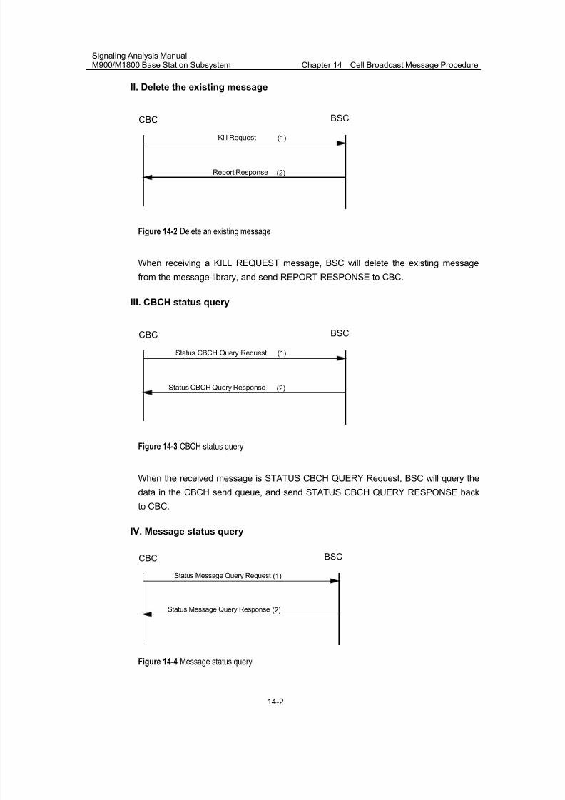
7/30/2019 Signaling Analysis Manual
http://slidepdf.com/reader/full/signaling-analysis-manual 159/290
Signaling Analysis ManualM900/M1800 Base Station Subsystem Chapter 14 Cell Broadcast Message Procedure
14-2
II. Delete the existing message
BSCCBC
Kill Request (1)
Report Response (2)
Figure 14-2 Delete an existing message
When receiving a KILL REQUEST message, BSC will delete the existing messagefrom the message library, and send REPORT RESPONSE to CBC.
III. CBCH status query
BSCCBC
Status CBCH Query Response
(1)
(2)
Status CBCH Query Request
Figure 14-3 CBCH status query
When the received message is STATUS CBCH QUERY Request, BSC will query the
data in the CBCH send queue, and send STATUS CBCH QUERY RESPONSE back
to CBC.
IV. Message status query
BSCCBC
Status Message Query Response
(1)
(2)
Status Message Query Request
Figure 14-4 Message status query
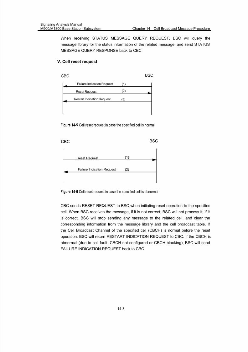
7/30/2019 Signaling Analysis Manual
http://slidepdf.com/reader/full/signaling-analysis-manual 160/290
Signaling Analysis ManualM900/M1800 Base Station Subsystem Chapter 14 Cell Broadcast Message Procedure
14-3
When receiving STATUS MESSAGE QUERY REQUEST, BSC will query the
message library for the status information of the related message, and send STATUS
MESSAGE QUERY RESPONSE back to CBC.
V. Cell reset request
BSCCBC
Restart Indication Request
(1)
(3)
Failure Indication Request
Reset Request (2)
Figure 14-5 Cell reset request in case the specified cell is normal
BSCCBC
(2)Failure Indication Request
Reset Request (1)
Figure 14-6 Cell reset request in case the specified cell is abnormal
CBC sends RESET REQUEST to BSC when initiating reset operation to the specified
cell. When BSC receives the message, if it is not correct, BSC will not process it; if it
is correct, BSC will stop sending any message to the related cell, and clear the
corresponding information from the message library and the cell broadcast table. If
the Cell Broadcast Channel of the specified cell (CBCH) is normal before the reset
operation, BSC will return RESTART INDICATION REQUEST to CBC. If the CBCH is
abnormal (due to cell fault, CBCH not configured or CBCH blocking), BSC will send
FAILURE INDICATION REQUEST back to CBC.
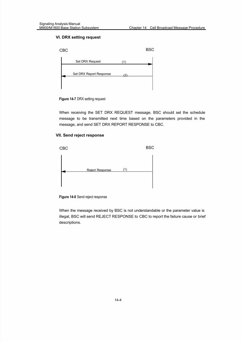
7/30/2019 Signaling Analysis Manual
http://slidepdf.com/reader/full/signaling-analysis-manual 161/290
Signaling Analysis ManualM900/M1800 Base Station Subsystem Chapter 14 Cell Broadcast Message Procedure
14-4
VI. DRX setting request
BSCCBC
Set DRX Report Response
(1)Set DRX Request
(2)
Figure 14-7 DRX setting request
When receiving the SET DRX REQUEST message, BSC should set the schedulemessage to be transmitted next time based on the parameters provided in the
message, and send SET DRX REPORT RESPONSE to CBC.
VII. Send reject response
BSCCBC
(1)Reject Response
Figure 14-8 Send reject response
When the message received by BSC is not understandable or the parameter value is
illegal, BSC will send REJECT RESPONSE to CBC to report the failure cause or brief
descriptions.
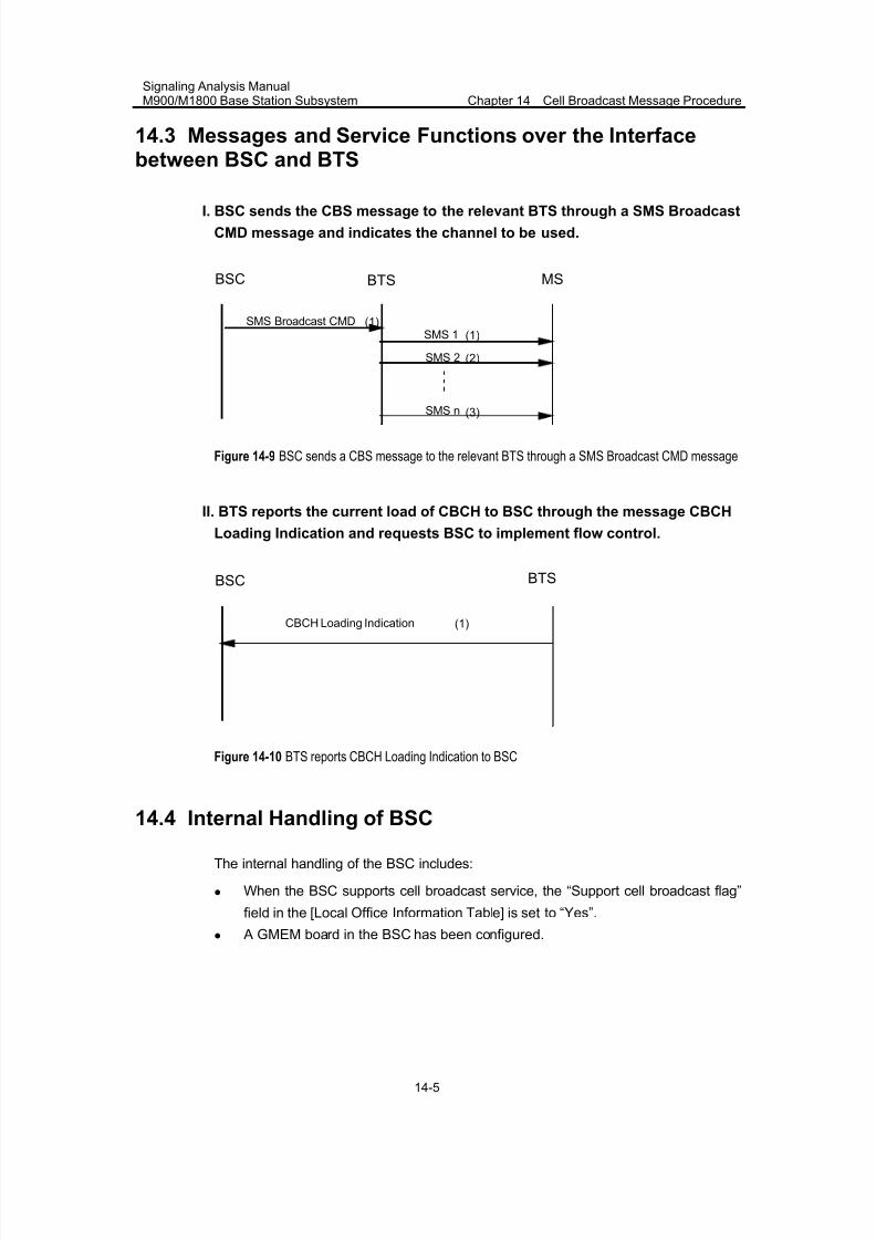
7/30/2019 Signaling Analysis Manual
http://slidepdf.com/reader/full/signaling-analysis-manual 162/290
Signaling Analysis ManualM900/M1800 Base Station Subsystem Chapter 14 Cell Broadcast Message Procedure
14-5
14.3 Messages and Service Functions over the Interfacebetween BSC and BTS
I. BSC sends the CBS message to the relevant BTS through a SMS Broadcast
CMD message and indicates the channel to be used.
MSBSC
(1)SMS Broadcast CMDSMS 1
SMS 2
SMS n
(1)
(2)
(3)
BTS
Figure 14-9 BSC sends a CBS message to the relevant BTS through a SMS Broadcast CMD message
II. BTS reports the current load of CBCH to BSC through the message CBCH
Loading Indication and requests BSC to implement flow control.
BTSBSC
(1)CBCH Loading Indication
Figure 14-10 BTS reports CBCH Loading Indication to BSC
14.4 Internal Handling of BSC
The internal handling of the BSC includes:
z When the BSC supports cell broadcast service, the “Support cell broadcast flag”
field in the [Local Office Information Table] is set to “Yes”.
z A GMEM board in the BSC has been configured.

7/30/2019 Signaling Analysis Manual
http://slidepdf.com/reader/full/signaling-analysis-manual 163/290
Signaling Analysis ManualM900/M1800 Base Station Subsystem Chapter 14 Cell Broadcast Message Procedure
14-6
14.5 Abnormal Cases
The cell broadcast procedure generally does not involve abnormal signaling
procedure. Once the relevant parameters are correctly set to support normalcommunications, the basic cell broadcast message services can be available.
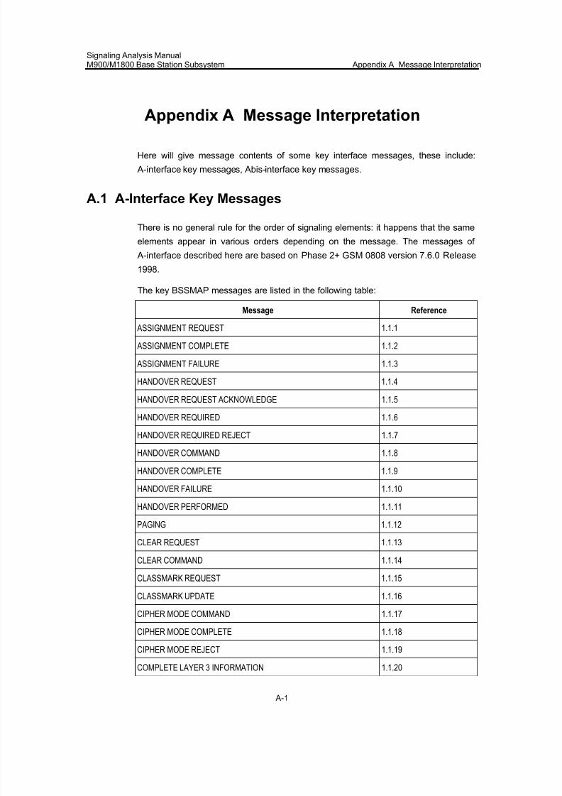
7/30/2019 Signaling Analysis Manual
http://slidepdf.com/reader/full/signaling-analysis-manual 164/290
Signaling Analysis ManualM900/M1800 Base Station Subsystem Appendix A Message Interpretation
A-1
Appendix A Message Interpretation
Here will give message contents of some key interface messages, these include:
A-interface key messages, Abis-interface key messages.
A.1 A-Interface Key Messages
There is no general rule for the order of signaling elements: it happens that the same
elements appear in various orders depending on the message. The messages of
A-interface described here are based on Phase 2+ GSM 0808 version 7.6.0 Release
1998.
The key BSSMAP messages are listed in the following table:
Message Reference
ASSIGNMENT REQUEST 1.1.1
ASSIGNMENT COMPLETE 1.1.2
ASSIGNMENT FAILURE 1.1.3
HANDOVER REQUEST 1.1.4
HANDOVER REQUEST ACKNOWLEDGE 1.1.5
HANDOVER REQUIRED 1.1.6
HANDOVER REQUIRED REJECT 1.1.7
HANDOVER COMMAND 1.1.8
HANDOVER COMPLETE 1.1.9
HANDOVER FAILURE 1.1.10
HANDOVER PERFORMED 1.1.11
PAGING 1.1.12
CLEAR REQUEST 1.1.13
CLEAR COMMAND 1.1.14
CLASSMARK REQUEST 1.1.15
CLASSMARK UPDATE 1.1.16
CIPHER MODE COMMAND 1.1.17
CIPHER MODE COMPLETE 1.1.18
CIPHER MODE REJECT 1.1.19
COMPLETE LAYER 3 INFORMATION 1.1.20
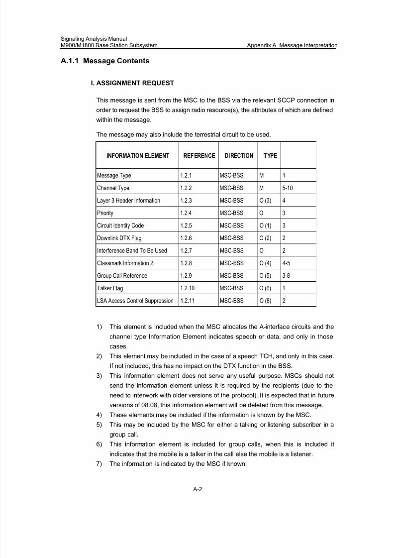
7/30/2019 Signaling Analysis Manual
http://slidepdf.com/reader/full/signaling-analysis-manual 165/290
Signaling Analysis ManualM900/M1800 Base Station Subsystem Appendix A Message Interpretation
A-2
A.1.1 Message Contents
I. ASSIGNMENT REQUEST
This message is sent from the MSC to the BSS via the relevant SCCP connection in
order to request the BSS to assign radio resource(s), the attributes of which are defined
within the message.
The message may also include the terrestrial circuit to be used.
INFORMATION ELEMENT REFERENCE DIRECTION TYPE
Message Type 1.2.1 MSC-BSS M 1
Channel Type 1.2.2 MSC-BSS M 5-10
Layer 3 Header Information 1.2.3 MSC-BSS O (3) 4
Priority 1.2.4 MSC-BSS O 3
Circuit Identity Code 1.2.5 MSC-BSS O (1) 3
Downlink DTX Flag 1.2.6 MSC-BSS O (2) 2
Interference Band To Be Used 1.2.7 MSC-BSS O 2
Classmark Information 2 1.2.8 MSC-BSS O (4) 4-5
Group Call Reference 1.2.9 MSC-BSS O (5) 3-8
Talker Flag 1.2.10 MSC-BSS O (6) 1
LSA Access Control Suppression 1.2.11 MSC-BSS O (8) 2
1) This element is included when the MSC allocates the A-interface circuits and the
channel type Information Element indicates speech or data, and only in those
cases.
2) This element may be included in the case of a speech TCH, and only in this case.
If not included, this has no impact on the DTX function in the BSS.
3) This information element does not serve any useful purpose. MSCs should not
send the information element unless it is required by the recipients (due to the
need to interwork with older versions of the protocol). It is expected that in future
versions of 08.08, this information element will be deleted from this message.
4) These elements may be included if the information is known by the MSC.
5) This may be included by the MSC for either a talking or listening subscriber in a
group call.
6) This information element is included for group calls, when this is included it
indicates that the mobile is a talker in the call else the mobile is a listener.
7) The information is indicated by the MSC if known.
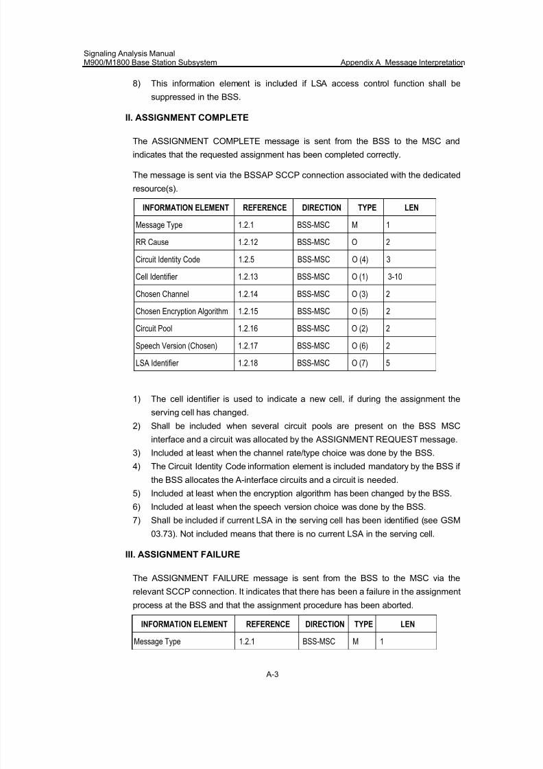
7/30/2019 Signaling Analysis Manual
http://slidepdf.com/reader/full/signaling-analysis-manual 166/290
Signaling Analysis ManualM900/M1800 Base Station Subsystem Appendix A Message Interpretation
A-3
8) This information element is included if LSA access control function shall be
suppressed in the BSS.
II. ASSIGNMENT COMPLETE
The ASSIGNMENT COMPLETE message is sent from the BSS to the MSC and
indicates that the requested assignment has been completed correctly.
The message is sent via the BSSAP SCCP connection associated with the dedicated
resource(s).
INFORMATION ELEMENT REFERENCE DIRECTION TYPE LEN
Message Type 1.2.1 BSS-MSC M 1
RR Cause 1.2.12 BSS-MSC O 2
Circuit Identity Code 1.2.5 BSS-MSC O (4) 3
Cell Identifier 1.2.13 BSS-MSC O (1) 3-10
Chosen Channel 1.2.14 BSS-MSC O (3) 2
Chosen Encryption Algorithm 1.2.15 BSS-MSC O (5) 2
Circuit Pool 1.2.16 BSS-MSC O (2) 2
Speech Version (Chosen) 1.2.17 BSS-MSC O (6) 2
LSA Identifier 1.2.18 BSS-MSC O (7) 5
1) The cell identifier is used to indicate a new cell, if during the assignment the
serving cell has changed.
2) Shall be included when several circuit pools are present on the BSS MSC
interface and a circuit was allocated by the ASSIGNMENT REQUEST message.
3) Included at least when the channel rate/type choice was done by the BSS.
4) The Circuit Identity Code information element is included mandatory by the BSS if
the BSS allocates the A-interface circuits and a circuit is needed.
5) Included at least when the encryption algorithm has been changed by the BSS.
6) Included at least when the speech version choice was done by the BSS.
7) Shall be included if current LSA in the serving cell has been identified (see GSM
03.73). Not included means that there is no current LSA in the serving cell.
III. ASSIGNMENT FAILURE
The ASSIGNMENT FAILURE message is sent from the BSS to the MSC via the
relevant SCCP connection. It indicates that there has been a failure in the assignment
process at the BSS and that the assignment procedure has been aborted.
INFORMATION ELEMENT REFERENCE DIRECTION TYPE LEN
Message Type 1.2.1 BSS-MSC M 1
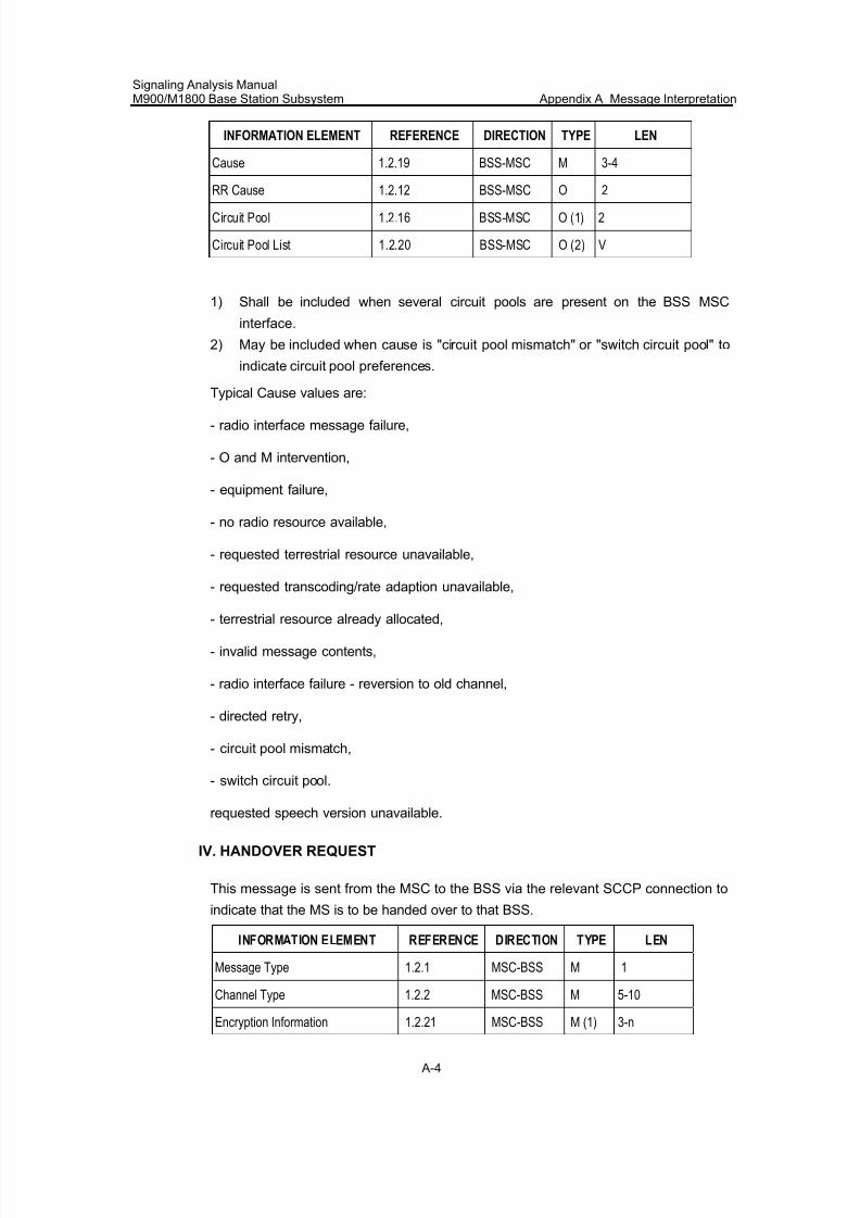
7/30/2019 Signaling Analysis Manual
http://slidepdf.com/reader/full/signaling-analysis-manual 167/290
Signaling Analysis ManualM900/M1800 Base Station Subsystem Appendix A Message Interpretation
A-4
INFORMATION ELEMENT REFERENCE DIRECTION TYPE LEN
Cause 1.2.19 BSS-MSC M 3-4
RR Cause 1.2.12 BSS-MSC O 2
Circuit Pool 1.2.16 BSS-MSC O (1) 2
Circuit Pool List 1.2.20 BSS-MSC O (2) V
1) Shall be included when several circuit pools are present on the BSS MSC
interface.
2) May be included when cause is "circuit pool mismatch" or "switch circuit pool" to
indicate circuit pool preferences.
Typical Cause values are:
- radio interface message failure,
- O and M intervention,
- equipment failure,
- no radio resource available,
- requested terrestrial resource unavailable,
- requested transcoding/rate adaption unavailable,
- terrestrial resource already allocated,
- invalid message contents,
- radio interface failure - reversion to old channel,
- directed retry,
- circuit pool mismatch,
- switch circuit pool.
requested speech version unavailable.
IV. HANDOVER REQUEST
This message is sent from the MSC to the BSS via the relevant SCCP connection to
indicate that the MS is to be handed over to that BSS.
INFORMATION ELEMENT REFERENCE DIRECTION TYPE LEN
Message Type 1.2.1 MSC-BSS M 1
Channel Type 1.2.2 MSC-BSS M 5-10
Encryption Information 1.2.21 MSC-BSS M (1) 3-n
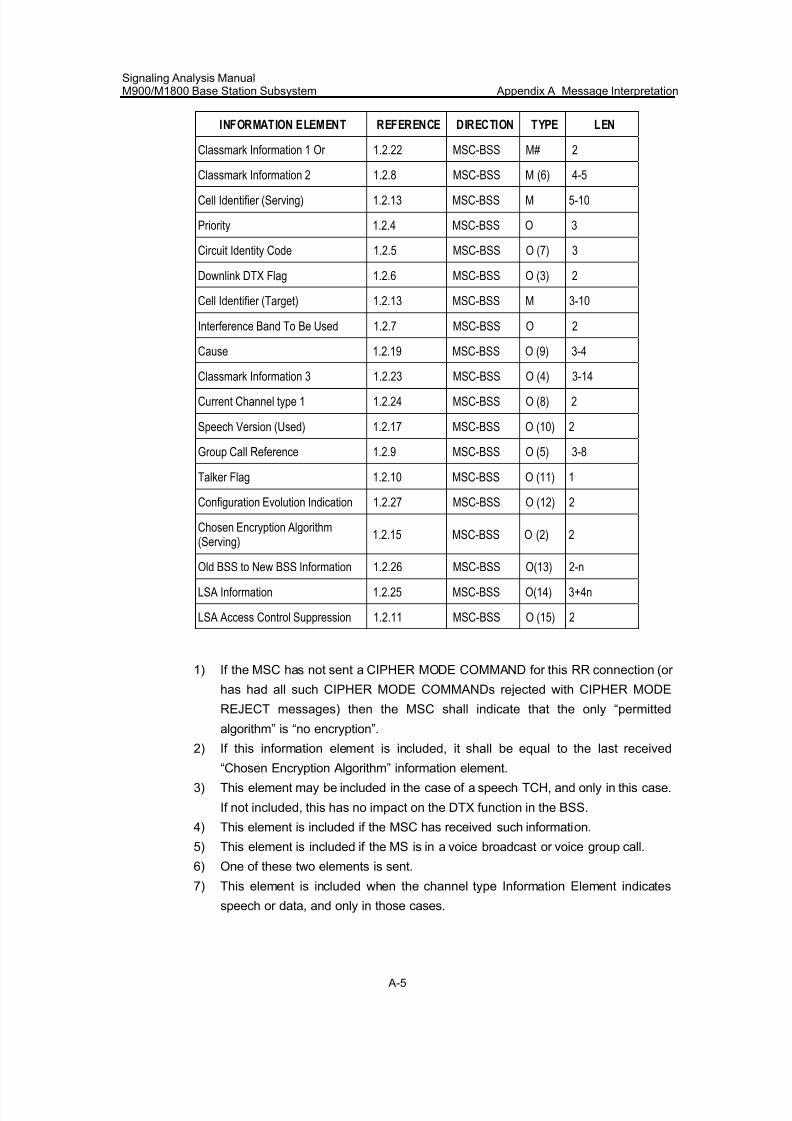
7/30/2019 Signaling Analysis Manual
http://slidepdf.com/reader/full/signaling-analysis-manual 168/290
Signaling Analysis ManualM900/M1800 Base Station Subsystem Appendix A Message Interpretation
A-5
INFORMATION ELEMENT REFERENCE DIRECTION TYPE LEN
Classmark Information 1 Or 1.2.22 MSC-BSS M# 2
Classmark Information 2 1.2.8 MSC-BSS M (6) 4-5
Cell Identifier (Serving) 1.2.13 MSC-BSS M 5-10
Priority 1.2.4 MSC-BSS O 3
Circuit Identity Code 1.2.5 MSC-BSS O (7) 3
Downlink DTX Flag 1.2.6 MSC-BSS O (3) 2
Cell Identifier (Target) 1.2.13 MSC-BSS M 3-10
Interference Band To Be Used 1.2.7 MSC-BSS O 2
Cause 1.2.19 MSC-BSS O (9) 3-4
Classmark Information 3 1.2.23 MSC-BSS O (4) 3-14
Current Channel type 1 1.2.24 MSC-BSS O (8) 2
Speech Version (Used) 1.2.17 MSC-BSS O (10) 2
Group Call Reference 1.2.9 MSC-BSS O (5) 3-8
Talker Flag 1.2.10 MSC-BSS O (11) 1
Configuration Evolution Indication 1.2.27 MSC-BSS O (12) 2
Chosen Encryption Algorithm(Serving)
1.2.15 MSC-BSS O (2) 2
Old BSS to New BSS Information 1.2.26 MSC-BSS O(13) 2-n
LSA Information 1.2.25 MSC-BSS O(14) 3+4n
LSA Access Control Suppression 1.2.11 MSC-BSS O (15) 2
1) If the MSC has not sent a CIPHER MODE COMMAND for this RR connection (or
has had all such CIPHER MODE COMMANDs rejected with CIPHER MODE
REJECT messages) then the MSC shall indicate that the only “permitted
algorithm” is “no encryption”.
2) If this information element is included, it shall be equal to the last received“Chosen Encryption Algorithm” information element.
3) This element may be included in the case of a speech TCH, and only in this case.
If not included, this has no impact on the DTX function in the BSS.
4) This element is included if the MSC has received such information.
5) This element is included if the MS is in a voice broadcast or voice group call.
6) One of these two elements is sent.
7) This element is included when the channel type Information Element indicates
speech or data, and only in those cases.
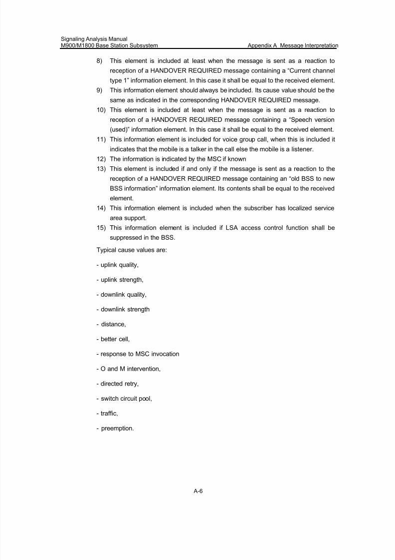
7/30/2019 Signaling Analysis Manual
http://slidepdf.com/reader/full/signaling-analysis-manual 169/290
Signaling Analysis ManualM900/M1800 Base Station Subsystem Appendix A Message Interpretation
A-6
8) This element is included at least when the message is sent as a reaction to
reception of a HANDOVER REQUIRED message containing a “Current channel
type 1” information element. In this case it shall be equal to the received element.
9) This information element should always be included. Its cause value should be thesame as indicated in the corresponding HANDOVER REQUIRED message.
10) This element is included at least when the message is sent as a reaction to
reception of a HANDOVER REQUIRED message containing a “Speech version
(used)” information element. In this case it shall be equal to the received element.
11) This information element is included for voice group call, when this is included it
indicates that the mobile is a talker in the call else the mobile is a listener.
12) The information is indicated by the MSC if known
13) This element is included if and only if the message is sent as a reaction to the
reception of a HANDOVER REQUIRED message containing an “old BSS to new
BSS information” information element. Its contents shall be equal to the received
element.
14) This information element is included when the subscriber has localized service
area support.
15) This information element is included if LSA access control function shall be
suppressed in the BSS.
Typical cause values are:
- uplink quality,
- uplink strength,
- downlink quality,
- downlink strength
- distance,
- better cell,
- response to MSC invocation
- O and M intervention,
- directed retry,
- switch circuit pool,
- traffic,
- preemption.
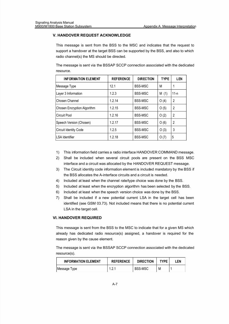
7/30/2019 Signaling Analysis Manual
http://slidepdf.com/reader/full/signaling-analysis-manual 170/290
Signaling Analysis ManualM900/M1800 Base Station Subsystem Appendix A Message Interpretation
A-7
V. HANDOVER REQUEST ACKNOWLEDGE
This message is sent from the BSS to the MSC and indicates that the request to
support a handover at the target BSS can be supported by the BSS, and also to which
radio channel(s) the MS should be directed.
The message is sent via the BSSAP SCCP connection associated with the dedicated
resource.
INFORMATION ELEMENT REFERENCE DIRECTION TYPE LEN
Message Type 12.1 BSS-MSC M 1
Layer 3 Information 1.2.3 BSS-MSC M (1) 11-n
Chosen Channel 1.2.14 BSS-MSC O (4) 2
Chosen Encryption Algorithm 1.2.15 BSS-MSC O (5) 2
Circuit Pool 1.2.16 BSS-MSC O (2) 2
Speech Version (Chosen) 1.2.17 BSS-MSC O (6) 2
Circuit Identity Code 1.2.5 BSS-MSC O (3) 3
LSA Identifier 1.2.18 BSS-MSC O (7) 5
1) This information field carries a radio interface HANDOVER COMMAND message.
2) Shall be included when several circuit pools are present on the BSS MSC
interface and a circuit was allocated by the HANDOVER REQUEST message.
3) The Circuit identity code information element is included mandatory by the BSS if
the BSS allocates the A-interface circuits and a circuit is needed.
4) Included at least when the channel rate/type choice was done by the BSS.
5) Included at least when the encryption algorithm has been selected by the BSS.
6) Included at least when the speech version choice was done by the BSS.
7) Shall be included if a new potential current LSA in the target cell has been
identified (see GSM 03.73). Not included means that there is no potential current
LSA in the target cell.
VI. HANDOVER REQUIRED
This message is sent from the BSS to the MSC to indicate that for a given MS which
already has dedicated radio resource(s) assigned, a handover is required for the
reason given by the cause element.
The message is sent via the BSSAP SCCP connection associated with the dedicated
resource(s).
INFORMATION ELEMENT REFERENCE DIRECTION TYPE LEN
Message Type 1.2.1 BSS-MSC M 1
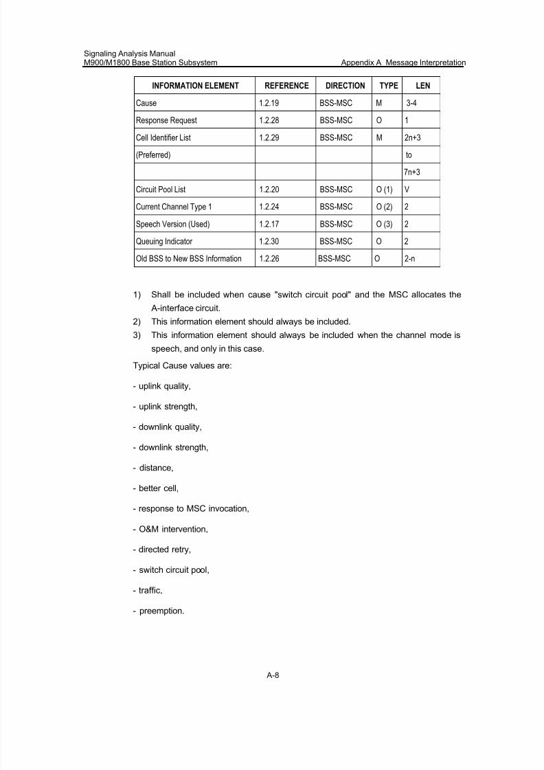
7/30/2019 Signaling Analysis Manual
http://slidepdf.com/reader/full/signaling-analysis-manual 171/290
Signaling Analysis ManualM900/M1800 Base Station Subsystem Appendix A Message Interpretation
A-8
INFORMATION ELEMENT REFERENCE DIRECTION TYPE LEN
Cause 1.2.19 BSS-MSC M 3-4
Response Request 1.2.28 BSS-MSC O 1
Cell Identifier List 1.2.29 BSS-MSC M 2n+3
(Preferred) to
7n+3
Circuit Pool List 1.2.20 BSS-MSC O (1) V
Current Channel Type 1 1.2.24 BSS-MSC O (2) 2
Speech Version (Used) 1.2.17 BSS-MSC O (3) 2
Queuing Indicator 1.2.30 BSS-MSC O 2
Old BSS to New BSS Information 1.2.26 BSS-MSC O 2-n
1) Shall be included when cause "switch circuit pool" and the MSC allocates the
A-interface circuit.
2) This information element should always be included.
3) This information element should always be included when the channel mode is
speech, and only in this case.
Typical Cause values are:
- uplink quality,
- uplink strength,
- downlink quality,
- downlink strength,
- distance,
- better cell,
- response to MSC invocation,
- O&M intervention,
- directed retry,
- switch circuit pool,
- traffic,
- preemption.
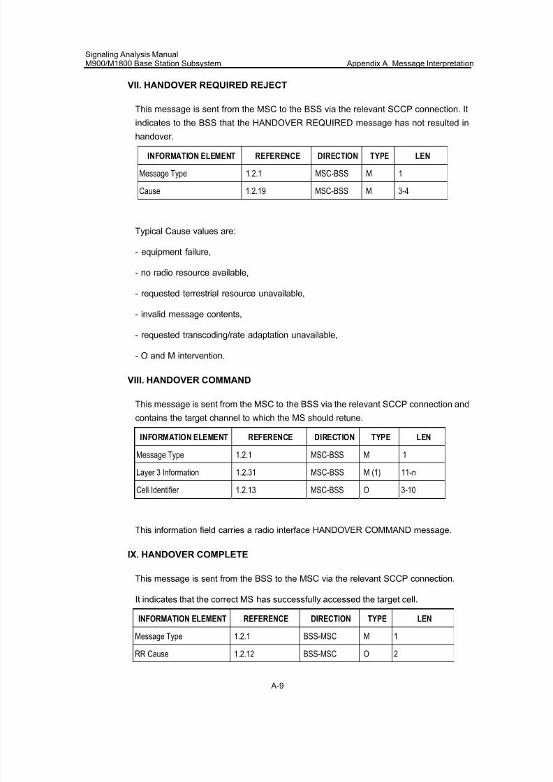
7/30/2019 Signaling Analysis Manual
http://slidepdf.com/reader/full/signaling-analysis-manual 172/290
Signaling Analysis ManualM900/M1800 Base Station Subsystem Appendix A Message Interpretation
A-9
VII. HANDOVER REQUIRED REJECT
This message is sent from the MSC to the BSS via the relevant SCCP connection. It
indicates to the BSS that the HANDOVER REQUIRED message has not resulted in
handover.
INFORMATION ELEMENT REFERENCE DIRECTION TYPE LEN
Message Type 1.2.1 MSC-BSS M 1
Cause 1.2.19 MSC-BSS M 3-4
Typical Cause values are:
- equipment failure,
- no radio resource available,
- requested terrestrial resource unavailable,
- invalid message contents,
- requested transcoding/rate adaptation unavailable,
- O and M intervention.
VIII. HANDOVER COMMAND
This message is sent from the MSC to the BSS via the relevant SCCP connection and
contains the target channel to which the MS should retune.
INFORMATION ELEMENT REFERENCE DIRECTION TYPE LEN
Message Type 1.2.1 MSC-BSS M 1
Layer 3 Information 1.2.31 MSC-BSS M (1) 11-n
Cell Identifier 1.2.13 MSC-BSS O 3-10
This information field carries a radio interface HANDOVER COMMAND message.
IX. HANDOVER COMPLETE
This message is sent from the BSS to the MSC via the relevant SCCP connection.
It indicates that the correct MS has successfully accessed the target cell.
INFORMATION ELEMENT REFERENCE DIRECTION TYPE LEN
Message Type 1.2.1 BSS-MSC M 1
RR Cause 1.2.12 BSS-MSC O 2
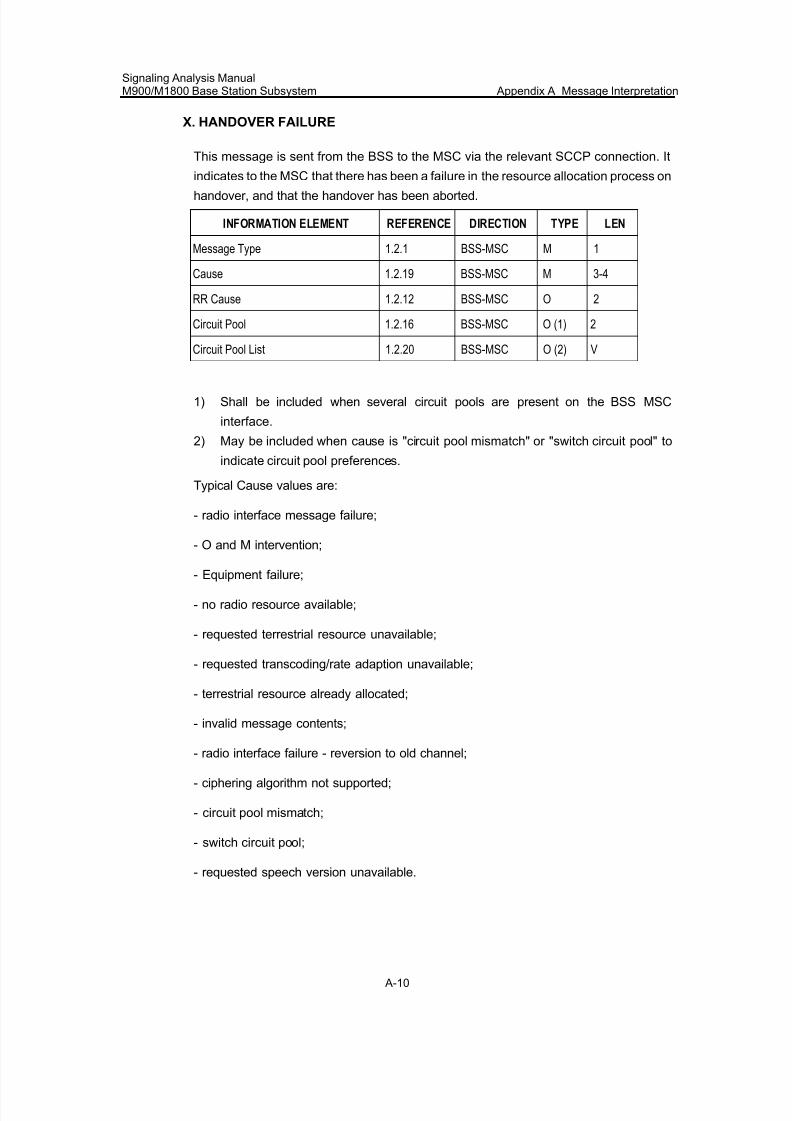
7/30/2019 Signaling Analysis Manual
http://slidepdf.com/reader/full/signaling-analysis-manual 173/290
Signaling Analysis ManualM900/M1800 Base Station Subsystem Appendix A Message Interpretation
A-10
X. HANDOVER FAILURE
This message is sent from the BSS to the MSC via the relevant SCCP connection. It
indicates to the MSC that there has been a failure in the resource allocation process on
handover, and that the handover has been aborted.
INFORMATION ELEMENT REFERENCE DIRECTION TYPE LEN
Message Type 1.2.1 BSS-MSC M 1
Cause 1.2.19 BSS-MSC M 3-4
RR Cause 1.2.12 BSS-MSC O 2
Circuit Pool 1.2.16 BSS-MSC O (1) 2
Circuit Pool List 1.2.20 BSS-MSC O (2) V
1) Shall be included when several circuit pools are present on the BSS MSC
interface.
2) May be included when cause is "circuit pool mismatch" or "switch circuit pool" to
indicate circuit pool preferences.
Typical Cause values are:
- radio interface message failure;
- O and M intervention;
- Equipment failure;
- no radio resource available;
- requested terrestrial resource unavailable;
- requested transcoding/rate adaption unavailable;
- terrestrial resource already allocated;
- invalid message contents;
- radio interface failure - reversion to old channel;
- ciphering algorithm not supported;
- circuit pool mismatch;
- switch circuit pool;
- requested speech version unavailable.
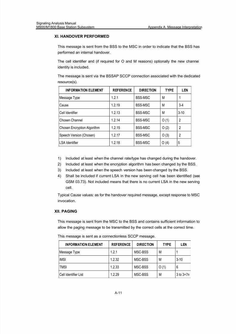
7/30/2019 Signaling Analysis Manual
http://slidepdf.com/reader/full/signaling-analysis-manual 174/290
Signaling Analysis ManualM900/M1800 Base Station Subsystem Appendix A Message Interpretation
A-11
XI. HANDOVER PERFORMED
This message is sent from the BSS to the MSC in order to indicate that the BSS has
performed an internal handover.
The cell identifier and (if required for O and M reasons) optionally the new channel
identity is included.
The message is sent via the BSSAP SCCP connection associated with the dedicated
resource(s).
INFORMATION ELEMENT REFERENCE DIRECTION TYPE LEN
Message Type 1.2.1 BSS-MSC M 1
Cause 1.2.19 BSS-MSC M 3-4
Cell Identifier 1.2.13 BSS-MSC M 3-10
Chosen Channel 1.2.14 BSS-MSC O (1) 2
Chosen Encryption Algorithm 1.2.15 BSS-MSC O (2) 2
Speech Version (Chosen) 1.2.17 BSS-MSC O (3) 2
LSA Identifier 1.2.18 BSS-MSC O (4) 5
1) Included at least when the channel rate/type has changed during the handover.
2) Included at least when the encryption algorithm has been changed by the BSS.
3) Included at least when the speech version has been changed by the BSS.
4) Shall be included if current LSA in the new serving cell has been identified (see
GSM 03.73). Not included means that there is no current LSA in the new serving
cell.
Typical Cause values: as for the handover required message, except response to MSC
invocation.
XII. PAGING
This message is sent from the MSC to the BSS and contains sufficient information toallow the paging message to be transmitted by the correct cells at the correct time.
This message is sent as a connectionless SCCP message.
INFORMATION ELEMENT REFERENCE DIRECTION TYPE LEN
Message Type 1.2.1 MSC-BSS M 1
IMSI 1.2.32 MSC-BSS M 3-10
TMSI 1.2.33 MSC-BSS O (1) 6
Cell Identifier List 1.2.29 MSC-BSS M 3 to 3+7n
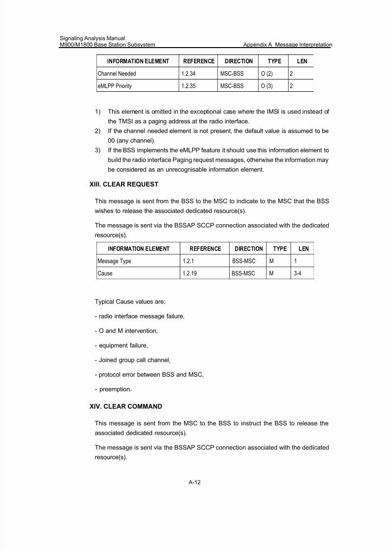
7/30/2019 Signaling Analysis Manual
http://slidepdf.com/reader/full/signaling-analysis-manual 175/290
Signaling Analysis ManualM900/M1800 Base Station Subsystem Appendix A Message Interpretation
A-12
INFORMATION ELEMENT REFERENCE DIRECTION TYPE LEN
Channel Needed 1.2.34 MSC-BSS O (2) 2
eMLPP Priority 1.2.35 MSC-BSS O (3) 2
1) This element is omitted in the exceptional case where the IMSI is used instead of
the TMSI as a paging address at the radio interface.
2) If the channel needed element is not present, the default value is assumed to be
00 (any channel).
3) If the BSS implements the eMLPP feature it should use this information element to
build the radio interface Paging request messages, otherwise the information may
be considered as an unrecognisable information element.
XIII. CLEAR REQUEST
This message is sent from the BSS to the MSC to indicate to the MSC that the BSS
wishes to release the associated dedicated resource(s).
The message is sent via the BSSAP SCCP connection associated with the dedicated
resource(s).
INFORMATION ELEMENT REFERENCE DIRECTION TYPE LEN
Message Type 1.2.1 BSS-MSC M 1
Cause 1.2.19 BSS-MSC M 3-4
Typical Cause values are:
- radio interface message failure,
- O and M intervention,
- equipment failure,
- Joined group call channel,
- protocol error between BSS and MSC,
- preemption.
XIV. CLEAR COMMAND
This message is sent from the MSC to the BSS to instruct the BSS to release the
associated dedicated resource(s).
The message is sent via the BSSAP SCCP connection associated with the dedicated
resource(s).
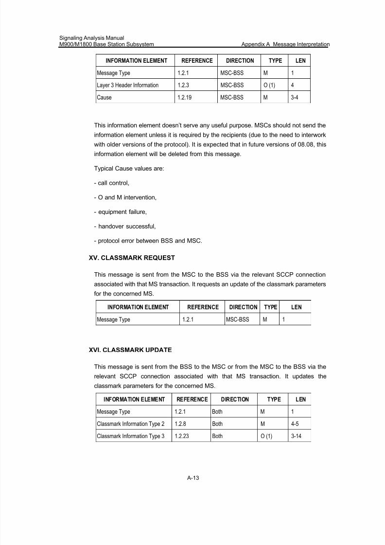
7/30/2019 Signaling Analysis Manual
http://slidepdf.com/reader/full/signaling-analysis-manual 176/290
Signaling Analysis ManualM900/M1800 Base Station Subsystem Appendix A Message Interpretation
A-13
INFORMATION ELEMENT REFERENCE DIRECTION TYPE LEN
Message Type 1.2.1 MSC-BSS M 1
Layer 3 Header Information 1.2.3 MSC-BSS O (1) 4
Cause 1.2.19 MSC-BSS M 3-4
This information element doesn’t serve any useful purpose. MSCs should not send the
information element unless it is required by the recipients (due to the need to interwork
with older versions of the protocol). It is expected that in future versions of 08.08, this
information element will be deleted from this message.
Typical Cause values are:
- call control,
- O and M intervention,
- equipment failure,
- handover successful,
- protocol error between BSS and MSC.
XV. CLASSMARK REQUEST
This message is sent from the MSC to the BSS via the relevant SCCP connection
associated with that MS transaction. It requests an update of the classmark parameters
for the concerned MS.
INFORMATION ELEMENT REFERENCE DIRECTION TYPE LEN
Message Type 1.2.1 MSC-BSS M 1
XVI. CLASSMARK UPDATE
This message is sent from the BSS to the MSC or from the MSC to the BSS via the
relevant SCCP connection associated with that MS transaction. It updates the
classmark parameters for the concerned MS.
INFORMATION ELEMENT REFERENCE DIRECTION TYPE LEN
Message Type 1.2.1 Both M 1
Classmark Information Type 2 1.2.8 Both M 4-5
Classmark Information Type 3 1.2.23 Both O (1) 3-14
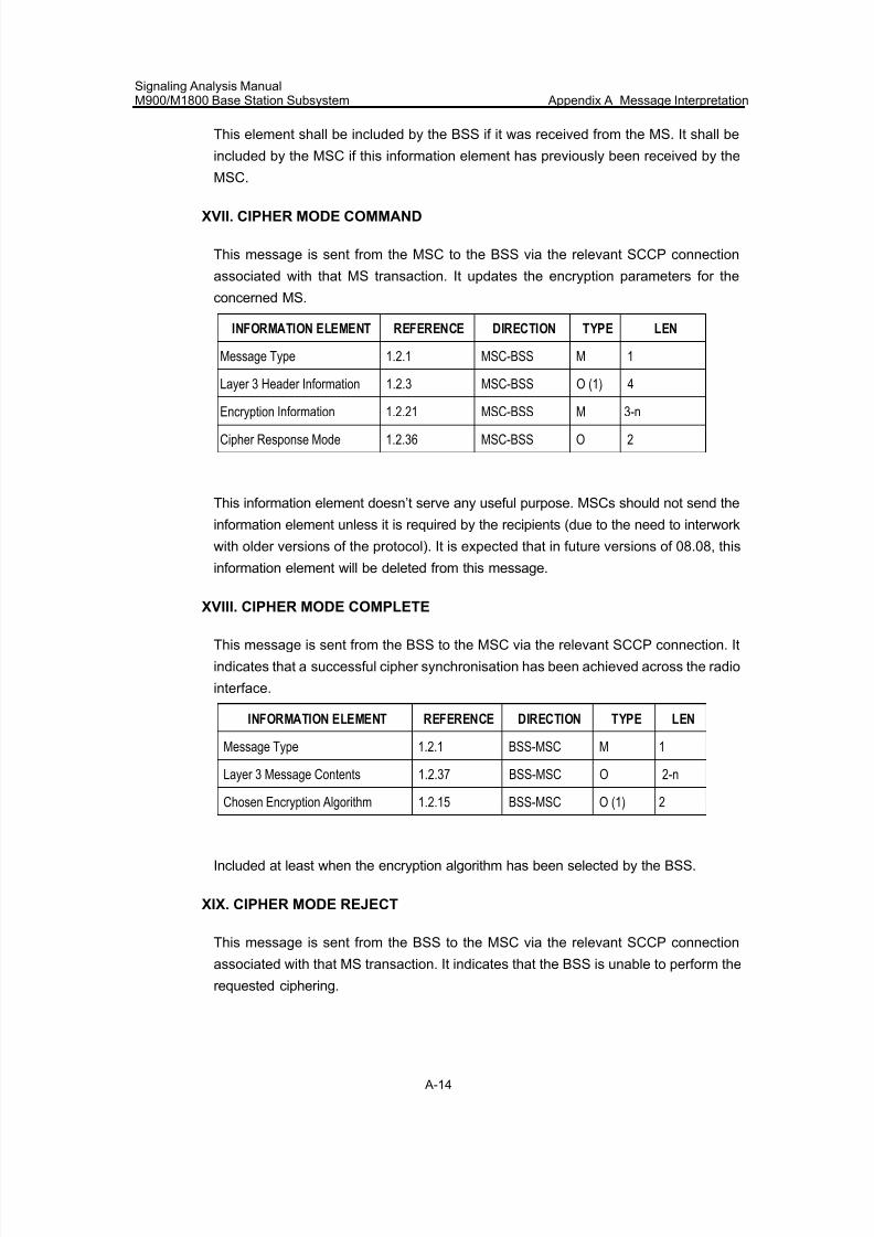
7/30/2019 Signaling Analysis Manual
http://slidepdf.com/reader/full/signaling-analysis-manual 177/290
Signaling Analysis ManualM900/M1800 Base Station Subsystem Appendix A Message Interpretation
A-14
This element shall be included by the BSS if it was received from the MS. It shall be
included by the MSC if this information element has previously been received by the
MSC.
XVII. CIPHER MODE COMMAND
This message is sent from the MSC to the BSS via the relevant SCCP connection
associated with that MS transaction. It updates the encryption parameters for the
concerned MS.
INFORMATION ELEMENT REFERENCE DIRECTION TYPE LEN
Message Type 1.2.1 MSC-BSS M 1
Layer 3 Header Information 1.2.3 MSC-BSS O (1) 4
Encryption Information 1.2.21 MSC-BSS M 3-n
Cipher Response Mode 1.2.36 MSC-BSS O 2
This information element doesn’t serve any useful purpose. MSCs should not send the
information element unless it is required by the recipients (due to the need to interwork
with older versions of the protocol). It is expected that in future versions of 08.08, this
information element will be deleted from this message.
XVIII. CIPHER MODE COMPLETE
This message is sent from the BSS to the MSC via the relevant SCCP connection. It
indicates that a successful cipher synchronisation has been achieved across the radio
interface.
INFORMATION ELEMENT REFERENCE DIRECTION TYPE LEN
Message Type 1.2.1 BSS-MSC M 1
Layer 3 Message Contents 1.2.37 BSS-MSC O 2-n
Chosen Encryption Algorithm 1.2.15 BSS-MSC O (1) 2
Included at least when the encryption algorithm has been selected by the BSS.
XIX. CIPHER MODE REJECT
This message is sent from the BSS to the MSC via the relevant SCCP connection
associated with that MS transaction. It indicates that the BSS is unable to perform the
requested ciphering.
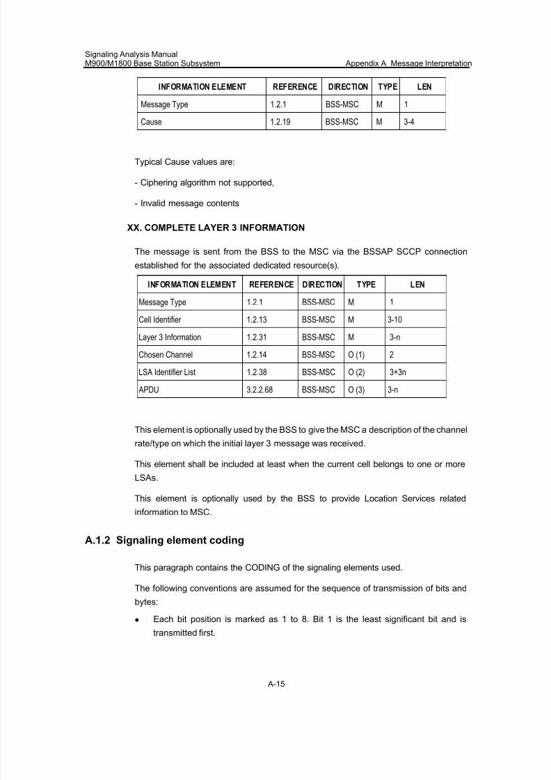
7/30/2019 Signaling Analysis Manual
http://slidepdf.com/reader/full/signaling-analysis-manual 178/290
Signaling Analysis ManualM900/M1800 Base Station Subsystem Appendix A Message Interpretation
A-15
INFORMATION ELEMENT REFERENCE DIRECTION TYPE LEN
Message Type 1.2.1 BSS-MSC M 1
Cause 1.2.19 BSS-MSC M 3-4
Typical Cause values are:
- Ciphering algorithm not supported,
- Invalid message contents
XX. COMPLETE LAYER 3 INFORMATION
The message is sent from the BSS to the MSC via the BSSAP SCCP connection
established for the associated dedicated resource(s).
INFORMATION ELEMENT REFERENCE DIRECTION TYPE LEN
Message Type 1.2.1 BSS-MSC M 1
Cell Identifier 1.2.13 BSS-MSC M 3-10
Layer 3 Information 1.2.31 BSS-MSC M 3-n
Chosen Channel 1.2.14 BSS-MSC O (1) 2
LSA Identifier List 1.2.38 BSS-MSC O (2) 3+3n
APDU 3.2.2.68 BSS-MSC O (3) 3-n
This element is optionally used by the BSS to give the MSC a description of the channel
rate/type on which the initial layer 3 message was received.
This element shall be included at least when the current cell belongs to one or more
LSAs.
This element is optionally used by the BSS to provide Location Services related
information to MSC.
A.1.2 Signaling element coding
This paragraph contains the CODING of the signaling elements used.
The following conventions are assumed for the sequence of transmission of bits and
bytes:
z Each bit position is marked as 1 to 8. Bit 1 is the least significant bit and is
transmitted first.
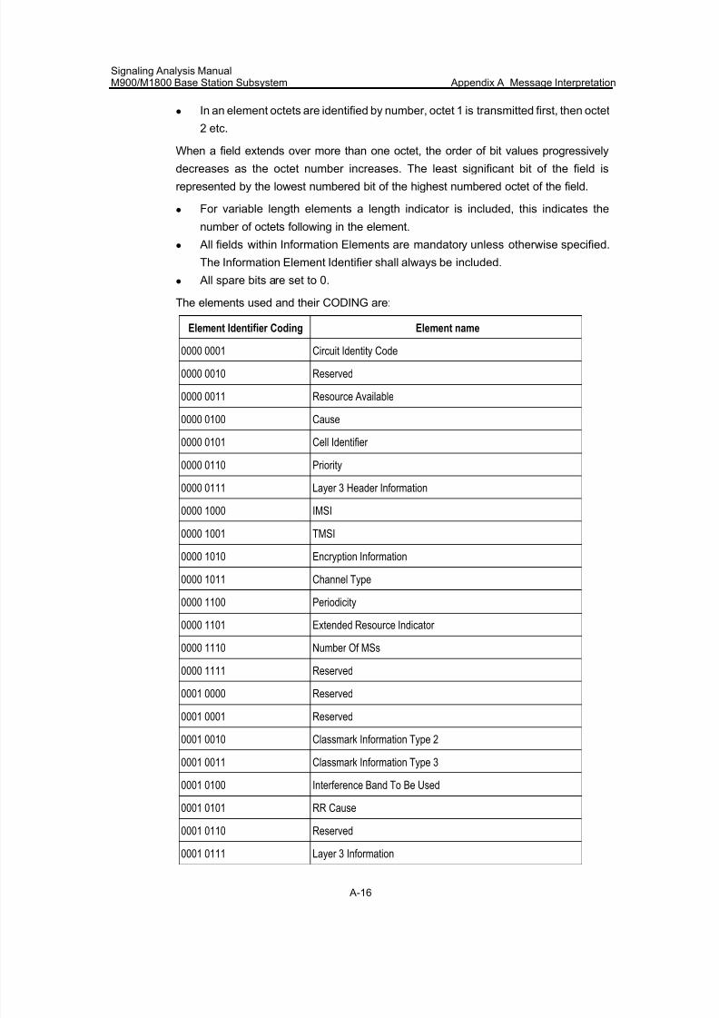
7/30/2019 Signaling Analysis Manual
http://slidepdf.com/reader/full/signaling-analysis-manual 179/290
Signaling Analysis ManualM900/M1800 Base Station Subsystem Appendix A Message Interpretation
A-16
z In an element octets are identified by number, octet 1 is transmitted first, then octet
2 etc.
When a field extends over more than one octet, the order of bit values progressively
decreases as the octet number increases. The least significant bit of the field isrepresented by the lowest numbered bit of the highest numbered octet of the field.
z For variable length elements a length indicator is included, this indicates the
number of octets following in the element.
z All fields within Information Elements are mandatory unless otherwise specified.
The Information Element Identifier shall always be included.
z All spare bits are set to 0.
The elements used and their CODING are:
Element Identifier Coding Element name
0000 0001 Circuit Identity Code
0000 0010 Reserved
0000 0011 Resource Available
0000 0100 Cause
0000 0101 Cell Identifier
0000 0110 Priority
0000 0111 Layer 3 Header Information
0000 1000 IMSI
0000 1001 TMSI
0000 1010 Encryption Information
0000 1011 Channel Type
0000 1100 Periodicity
0000 1101 Extended Resource Indicator
0000 1110 Number Of MSs
0000 1111 Reserved
0001 0000 Reserved
0001 0001 Reserved
0001 0010 Classmark Information Type 2
0001 0011 Classmark Information Type 3
0001 0100 Interference Band To Be Used
0001 0101 RR Cause
0001 0110 Reserved
0001 0111 Layer 3 Information
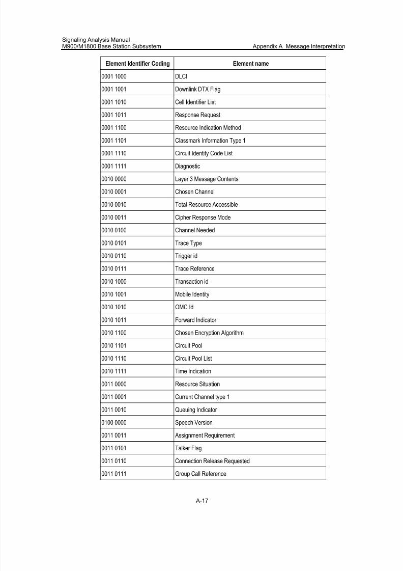
7/30/2019 Signaling Analysis Manual
http://slidepdf.com/reader/full/signaling-analysis-manual 180/290
Signaling Analysis ManualM900/M1800 Base Station Subsystem Appendix A Message Interpretation
A-17
Element Identifier Coding Element name
0001 1000 DLCI
0001 1001 Downlink DTX Flag
0001 1010 Cell Identifier List
0001 1011 Response Request
0001 1100 Resource Indication Method
0001 1101 Classmark Information Type 1
0001 1110 Circuit Identity Code List
0001 1111 Diagnostic
0010 0000 Layer 3 Message Contents
0010 0001 Chosen Channel
0010 0010 Total Resource Accessible
0010 0011 Cipher Response Mode
0010 0100 Channel Needed
0010 0101 Trace Type
0010 0110 Trigger id
0010 0111 Trace Reference
0010 1000 Transaction id
0010 1001 Mobile Identity
0010 1010 OMC Id
0010 1011 Forward Indicator
0010 1100 Chosen Encryption Algorithm
0010 1101 Circuit Pool
0010 1110 Circuit Pool List
0010 1111 Time Indication
0011 0000 Resource Situation
0011 0001 Current Channel type 1
0011 0010 Queuing Indicator
0100 0000 Speech Version
0011 0011 Assignment Requirement
0011 0101 Talker Flag
0011 0110 Connection Release Requested
0011 0111 Group Call Reference
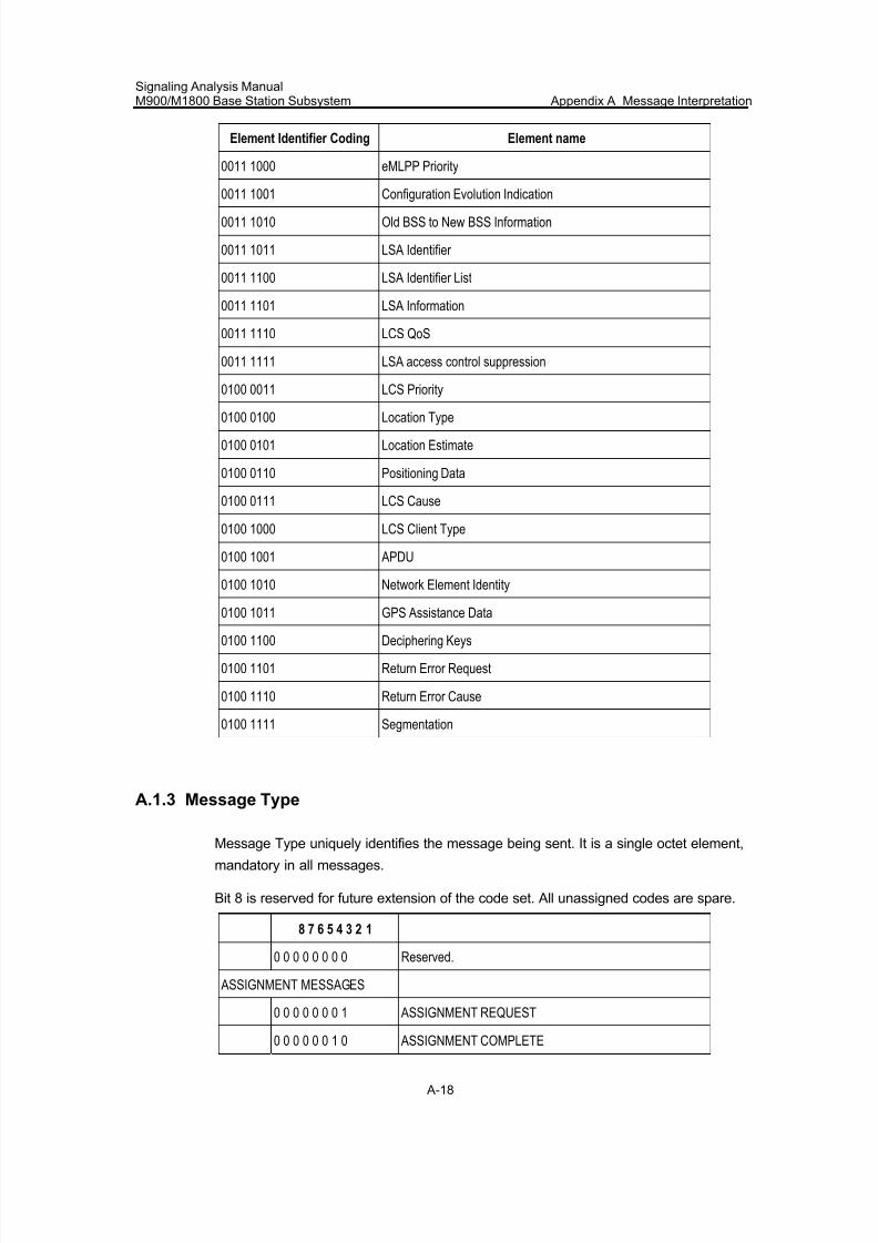
7/30/2019 Signaling Analysis Manual
http://slidepdf.com/reader/full/signaling-analysis-manual 181/290
Signaling Analysis ManualM900/M1800 Base Station Subsystem Appendix A Message Interpretation
A-18
Element Identifier Coding Element name
0011 1000 eMLPP Priority
0011 1001 Configuration Evolution Indication
0011 1010 Old BSS to New BSS Information
0011 1011 LSA Identifier
0011 1100 LSA Identifier List
0011 1101 LSA Information
0011 1110 LCS QoS
0011 1111 LSA access control suppression
0100 0011 LCS Priority
0100 0100 Location Type
0100 0101 Location Estimate
0100 0110 Positioning Data
0100 0111 LCS Cause
0100 1000 LCS Client Type
0100 1001 APDU
0100 1010 Network Element Identity
0100 1011 GPS Assistance Data
0100 1100 Deciphering Keys
0100 1101 Return Error Request
0100 1110 Return Error Cause
0100 1111 Segmentation
A.1.3 Message Type
Message Type uniquely identifies the message being sent. It is a single octet element,
mandatory in all messages.
Bit 8 is reserved for future extension of the code set. All unassigned codes are spare.
8 7 6 5 4 3 2 1
0 0 0 0 0 0 0 0 Reserved.
ASSIGNMENT MESSAGES
0 0 0 0 0 0 0 1 ASSIGNMENT REQUEST
0 0 0 0 0 0 1 0 ASSIGNMENT COMPLETE
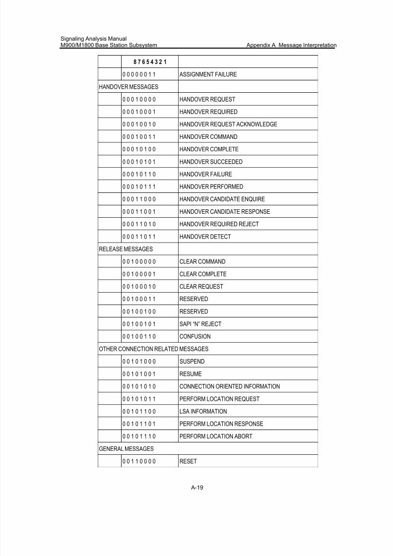
7/30/2019 Signaling Analysis Manual
http://slidepdf.com/reader/full/signaling-analysis-manual 182/290
Signaling Analysis ManualM900/M1800 Base Station Subsystem Appendix A Message Interpretation
A-19
8 7 6 5 4 3 2 1
0 0 0 0 0 0 1 1 ASSIGNMENT FAILURE
HANDOVER MESSAGES
0 0 0 1 0 0 0 0 HANDOVER REQUEST
0 0 0 1 0 0 0 1 HANDOVER REQUIRED
0 0 0 1 0 0 1 0 HANDOVER REQUEST ACKNOWLEDGE
0 0 0 1 0 0 1 1 HANDOVER COMMAND
0 0 0 1 0 1 0 0 HANDOVER COMPLETE
0 0 0 1 0 1 0 1 HANDOVER SUCCEEDED
0 0 0 1 0 1 1 0 HANDOVER FAILURE
0 0 0 1 0 1 1 1 HANDOVER PERFORMED
0 0 0 1 1 0 0 0 HANDOVER CANDIDATE ENQUIRE
0 0 0 1 1 0 0 1 HANDOVER CANDIDATE RESPONSE
0 0 0 1 1 0 1 0 HANDOVER REQUIRED REJECT
0 0 0 1 1 0 1 1 HANDOVER DETECT
RELEASE MESSAGES
0 0 1 0 0 0 0 0 CLEAR COMMAND
0 0 1 0 0 0 0 1 CLEAR COMPLETE
0 0 1 0 0 0 1 0 CLEAR REQUEST
0 0 1 0 0 0 1 1 RESERVED
0 0 1 0 0 1 0 0 RESERVED
0 0 1 0 0 1 0 1 SAPI “N” REJECT
0 0 1 0 0 1 1 0 CONFUSION
OTHER CONNECTION RELATED MESSAGES
0 0 1 0 1 0 0 0 SUSPEND
0 0 1 0 1 0 0 1 RESUME
0 0 1 0 1 0 1 0 CONNECTION ORIENTED INFORMATION
0 0 1 0 1 0 1 1 PERFORM LOCATION REQUEST
0 0 1 0 1 1 0 0 LSA INFORMATION
0 0 1 0 1 1 0 1 PERFORM LOCATION RESPONSE
0 0 1 0 1 1 1 0 PERFORM LOCATION ABORT
GENERAL MESSAGES
0 0 1 1 0 0 0 0 RESET
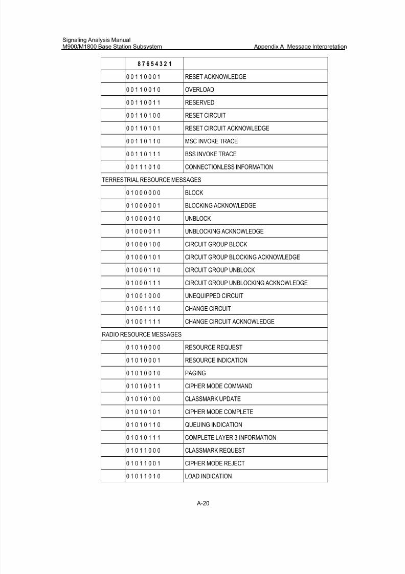
7/30/2019 Signaling Analysis Manual
http://slidepdf.com/reader/full/signaling-analysis-manual 183/290
Signaling Analysis ManualM900/M1800 Base Station Subsystem Appendix A Message Interpretation
A-20
8 7 6 5 4 3 2 1
0 0 1 1 0 0 0 1 RESET ACKNOWLEDGE
0 0 1 1 0 0 1 0 OVERLOAD
0 0 1 1 0 0 1 1 RESERVED
0 0 1 1 0 1 0 0 RESET CIRCUIT
0 0 1 1 0 1 0 1 RESET CIRCUIT ACKNOWLEDGE
0 0 1 1 0 1 1 0 MSC INVOKE TRACE
0 0 1 1 0 1 1 1 BSS INVOKE TRACE
0 0 1 1 1 0 1 0 CONNECTIONLESS INFORMATION
TERRESTRIAL RESOURCE MESSAGES
0 1 0 0 0 0 0 0 BLOCK
0 1 0 0 0 0 0 1 BLOCKING ACKNOWLEDGE
0 1 0 0 0 0 1 0 UNBLOCK
0 1 0 0 0 0 1 1 UNBLOCKING ACKNOWLEDGE
0 1 0 0 0 1 0 0 CIRCUIT GROUP BLOCK
0 1 0 0 0 1 0 1 CIRCUIT GROUP BLOCKING ACKNOWLEDGE
0 1 0 0 0 1 1 0 CIRCUIT GROUP UNBLOCK
0 1 0 0 0 1 1 1 CIRCUIT GROUP UNBLOCKING ACKNOWLEDGE
0 1 0 0 1 0 0 0 UNEQUIPPED CIRCUIT
0 1 0 0 1 1 1 0 CHANGE CIRCUIT
0 1 0 0 1 1 1 1 CHANGE CIRCUIT ACKNOWLEDGE
RADIO RESOURCE MESSAGES
0 1 0 1 0 0 0 0 RESOURCE REQUEST
0 1 0 1 0 0 0 1 RESOURCE INDICATION
0 1 0 1 0 0 1 0 PAGING
0 1 0 1 0 0 1 1 CIPHER MODE COMMAND
0 1 0 1 0 1 0 0 CLASSMARK UPDATE
0 1 0 1 0 1 0 1 CIPHER MODE COMPLETE
0 1 0 1 0 1 1 0 QUEUING INDICATION
0 1 0 1 0 1 1 1 COMPLETE LAYER 3 INFORMATION
0 1 0 1 1 0 0 0 CLASSMARK REQUEST
0 1 0 1 1 0 0 1 CIPHER MODE REJECT
0 1 0 1 1 0 1 0 LOAD INDICATION
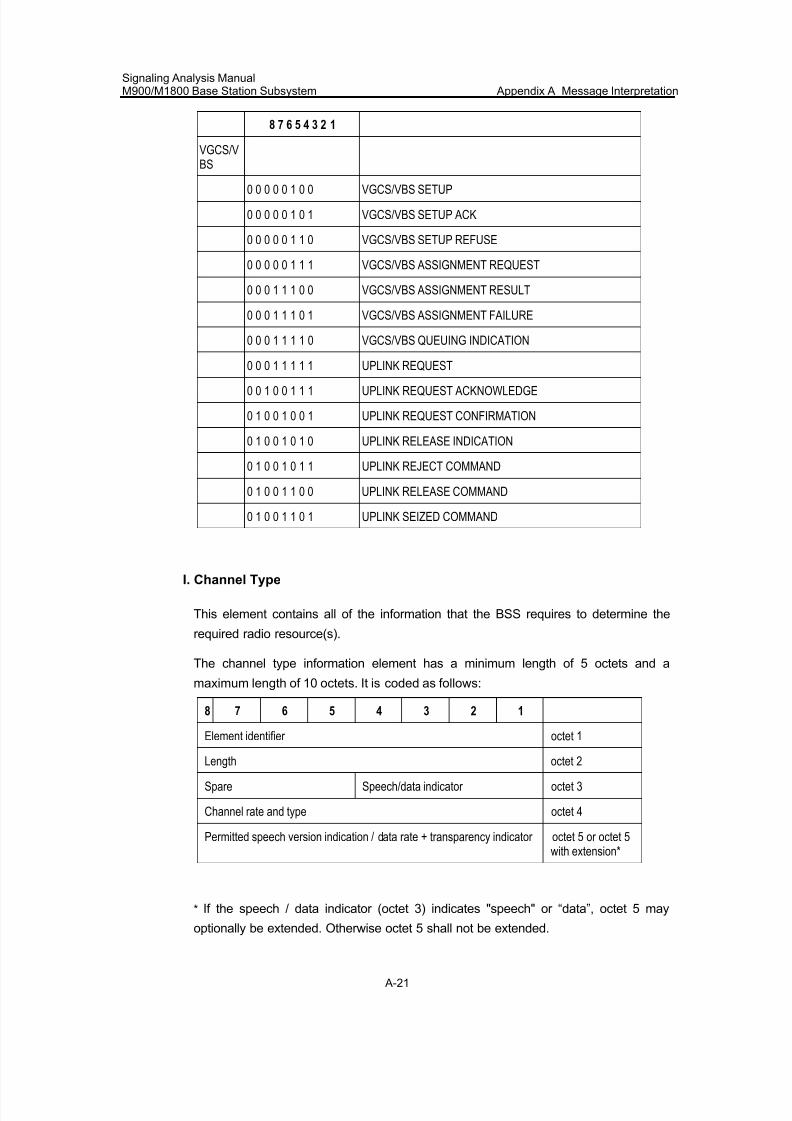
7/30/2019 Signaling Analysis Manual
http://slidepdf.com/reader/full/signaling-analysis-manual 184/290
Signaling Analysis ManualM900/M1800 Base Station Subsystem Appendix A Message Interpretation
A-21
8 7 6 5 4 3 2 1
VGCS/VBS
0 0 0 0 0 1 0 0 VGCS/VBS SETUP
0 0 0 0 0 1 0 1 VGCS/VBS SETUP ACK
0 0 0 0 0 1 1 0 VGCS/VBS SETUP REFUSE
0 0 0 0 0 1 1 1 VGCS/VBS ASSIGNMENT REQUEST
0 0 0 1 1 1 0 0 VGCS/VBS ASSIGNMENT RESULT
0 0 0 1 1 1 0 1 VGCS/VBS ASSIGNMENT FAILURE
0 0 0 1 1 1 1 0 VGCS/VBS QUEUING INDICATION
0 0 0 1 1 1 1 1 UPLINK REQUEST
0 0 1 0 0 1 1 1 UPLINK REQUEST ACKNOWLEDGE
0 1 0 0 1 0 0 1 UPLINK REQUEST CONFIRMATION
0 1 0 0 1 0 1 0 UPLINK RELEASE INDICATION
0 1 0 0 1 0 1 1 UPLINK REJECT COMMAND
0 1 0 0 1 1 0 0 UPLINK RELEASE COMMAND
0 1 0 0 1 1 0 1 UPLINK SEIZED COMMAND
I. Channel Type
This element contains all of the information that the BSS requires to determine the
required radio resource(s).
The channel type information element has a minimum length of 5 octets and a
maximum length of 10 octets. It is coded as follows:
8 7 6 5 4 3 2 1
Element identifier octet 1
Length octet 2
Spare Speech/data indicator octet 3
Channel rate and type octet 4
Permitted speech version indication / data rate + transparency indicator octet 5 or octet 5with extension*
* If the speech / data indicator (octet 3) indicates "speech" or “data”, octet 5 may
optionally be extended. Otherwise octet 5 shall not be extended.
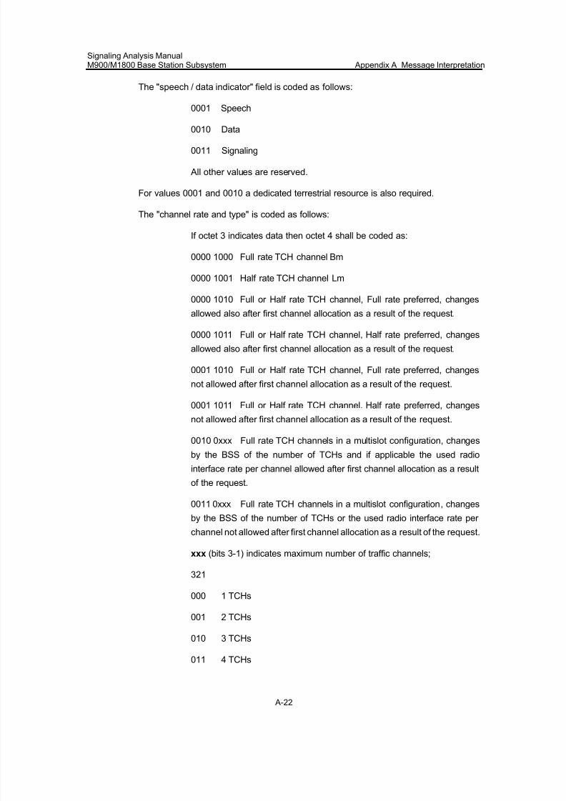
7/30/2019 Signaling Analysis Manual
http://slidepdf.com/reader/full/signaling-analysis-manual 185/290
Signaling Analysis ManualM900/M1800 Base Station Subsystem Appendix A Message Interpretation
A-22
The "speech / data indicator" field is coded as follows:
0001 Speech
0010 Data
0011 Signaling
All other values are reserved.
For values 0001 and 0010 a dedicated terrestrial resource is also required.
The "channel rate and type" is coded as follows:
If octet 3 indicates data then octet 4 shall be coded as:
0000 1000 Full rate TCH channel Bm
0000 1001 Half rate TCH channel Lm
0000 1010 Full or Half rate TCH channel, Full rate preferred, changes
allowed also after first channel allocation as a result of the request.
0000 1011 Full or Half rate TCH channel, Half rate preferred, changes
allowed also after first channel allocation as a result of the request.
0001 1010 Full or Half rate TCH channel, Full rate preferred, changes
not allowed after first channel allocation as a result of the request.
0001 1011 Full or Half rate TCH channel. Half rate preferred, changes
not allowed after first channel allocation as a result of the request.
0010 0xxx Full rate TCH channels in a multislot configuration, changes
by the BSS of the number of TCHs and if applicable the used radio
interface rate per channel allowed after first channel allocation as a result
of the request.
0011 0xxx Full rate TCH channels in a multislot configuration, changes
by the BSS of the number of TCHs or the used radio interface rate per
channel not allowed after first channel allocation as a result of the request.
xxx (bits 3-1) indicates maximum number of traffic channels;
321
000 1 TCHs
001 2 TCHs
010 3 TCHs
011 4 TCHs
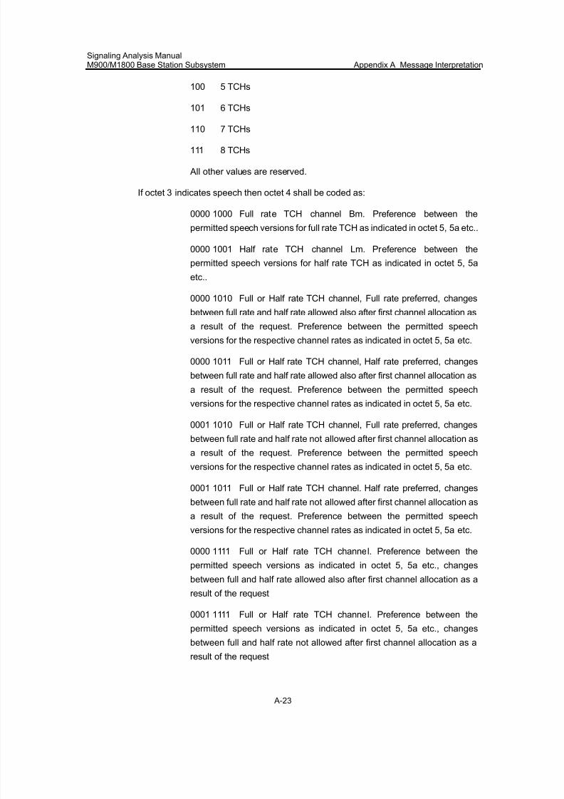
7/30/2019 Signaling Analysis Manual
http://slidepdf.com/reader/full/signaling-analysis-manual 186/290
Signaling Analysis ManualM900/M1800 Base Station Subsystem Appendix A Message Interpretation
A-23
100 5 TCHs
101 6 TCHs
110 7 TCHs
111 8 TCHs
All other values are reserved.
If octet 3 indicates speech then octet 4 shall be coded as:
0000 1000 Full rate TCH channel Bm. Preference between the
permitted speech versions for full rate TCH as indicated in octet 5, 5a etc..
0000 1001 Half rate TCH channel Lm. Preference between the
permitted speech versions for half rate TCH as indicated in octet 5, 5aetc..
0000 1010 Full or Half rate TCH channel, Full rate preferred, changes
between full rate and half rate allowed also after first channel allocation as
a result of the request. Preference between the permitted speech
versions for the respective channel rates as indicated in octet 5, 5a etc.
0000 1011 Full or Half rate TCH channel, Half rate preferred, changes
between full rate and half rate allowed also after first channel allocation as
a result of the request. Preference between the permitted speech
versions for the respective channel rates as indicated in octet 5, 5a etc.
0001 1010 Full or Half rate TCH channel, Full rate preferred, changes
between full rate and half rate not allowed after first channel allocation as
a result of the request. Preference between the permitted speech
versions for the respective channel rates as indicated in octet 5, 5a etc.
0001 1011 Full or Half rate TCH channel. Half rate preferred, changes
between full rate and half rate not allowed after first channel allocation as
a result of the request. Preference between the permitted speech
versions for the respective channel rates as indicated in octet 5, 5a etc.
0000 1111 Full or Half rate TCH channel. Preference between the
permitted speech versions as indicated in octet 5, 5a etc., changes
between full and half rate allowed also after first channel allocation as a
result of the request
0001 1111 Full or Half rate TCH channel. Preference between the
permitted speech versions as indicated in octet 5, 5a etc., changes
between full and half rate not allowed after first channel allocation as a
result of the request
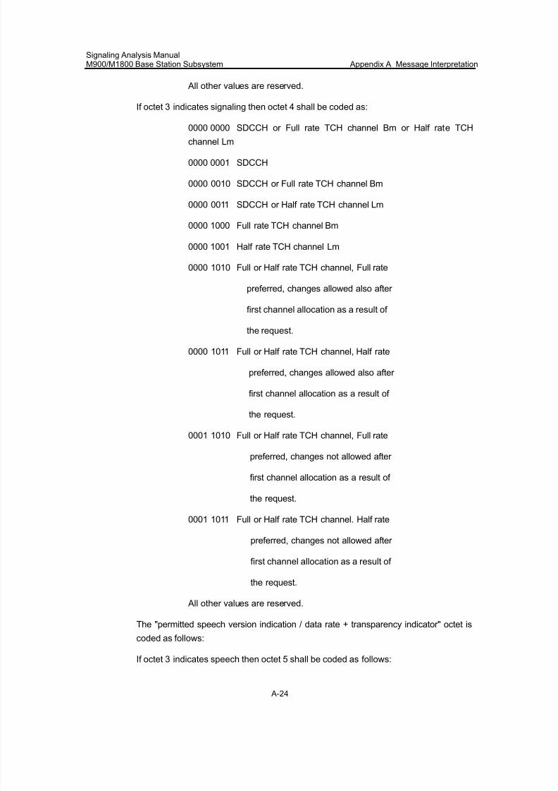
7/30/2019 Signaling Analysis Manual
http://slidepdf.com/reader/full/signaling-analysis-manual 187/290
Signaling Analysis ManualM900/M1800 Base Station Subsystem Appendix A Message Interpretation
A-24
All other values are reserved.
If octet 3 indicates signaling then octet 4 shall be coded as:
0000 0000 SDCCH or Full rate TCH channel Bm or Half rate TCHchannel Lm
0000 0001 SDCCH
0000 0010 SDCCH or Full rate TCH channel Bm
0000 0011 SDCCH or Half rate TCH channel Lm
0000 1000 Full rate TCH channel Bm
0000 1001 Half rate TCH channel Lm
0000 1010 Full or Half rate TCH channel, Full rate
preferred, changes allowed also after
first channel allocation as a result of
the request.
0000 1011 Full or Half rate TCH channel, Half rate
preferred, changes allowed also after
first channel allocation as a result of
the request.
0001 1010 Full or Half rate TCH channel, Full rate
preferred, changes not allowed after
first channel allocation as a result of
the request.
0001 1011 Full or Half rate TCH channel. Half rate
preferred, changes not allowed after
first channel allocation as a result of
the request.
All other values are reserved.
The "permitted speech version indication / data rate + transparency indicator" octet is
coded as follows:
If octet 3 indicates speech then octet 5 shall be coded as follows:
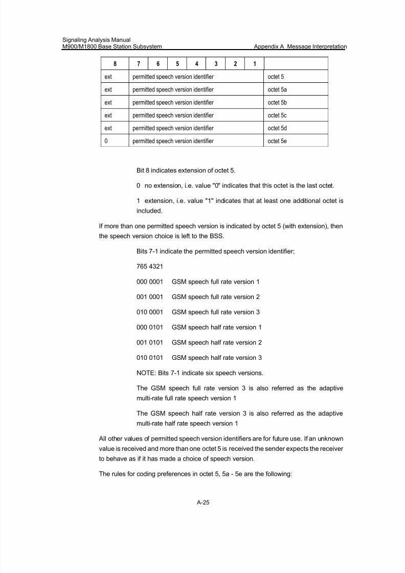
7/30/2019 Signaling Analysis Manual
http://slidepdf.com/reader/full/signaling-analysis-manual 188/290
Signaling Analysis ManualM900/M1800 Base Station Subsystem Appendix A Message Interpretation
A-25
8 7 6 5 4 3 2 1
ext permitted speech version identifier octet 5
ext permitted speech version identifier octet 5a
ext permitted speech version identifier octet 5b
ext permitted speech version identifier octet 5c
ext permitted speech version identifier octet 5d
0 permitted speech version identifier octet 5e
Bit 8 indicates extension of octet 5.
0 no extension, i.e. value "0" indicates that this octet is the last octet.
1 extension, i.e. value "1" indicates that at least one additional octet is
included.
If more than one permitted speech version is indicated by octet 5 (with extension), then
the speech version choice is left to the BSS.
Bits 7-1 indicate the permitted speech version identifier;
765 4321
000 0001 GSM speech full rate version 1
001 0001 GSM speech full rate version 2
010 0001 GSM speech full rate version 3
000 0101 GSM speech half rate version 1
001 0101 GSM speech half rate version 2
010 0101 GSM speech half rate version 3
NOTE: Bits 7-1 indicate six speech versions.
The GSM speech full rate version 3 is also referred as the adaptive
multi-rate full rate speech version 1
The GSM speech half rate version 3 is also referred as the adaptive
multi-rate half rate speech version 1 All other values of permitted speech version identifiers are for future use. If an unknown
value is received and more than one octet 5 is received the sender expects the receiver
to behave as if it has made a choice of speech version.
The rules for coding preferences in octet 5, 5a - 5e are the following:
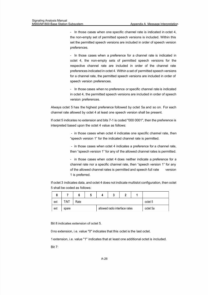
7/30/2019 Signaling Analysis Manual
http://slidepdf.com/reader/full/signaling-analysis-manual 189/290
Signaling Analysis ManualM900/M1800 Base Station Subsystem Appendix A Message Interpretation
A-26
- In those cases when one specific channel rate is indicated in octet 4,
the non-empty set of permitted speech versions is included. Within this
set the permitted speech versions are included in order of speech version
preferences.
- In those cases when a preference for a channel rate is indicated in
octet 4, the non-empty sets of permitted speech versions for the
respective channel rate are included in order of the channel rate
preferences indicated in octet 4. Within a set of permitted speech versions
for a channel rate, the permitted speech versions are included in order of
speech version preferences.
- In those cases when no preference or specific channel rate is indicated
in octet 4, the permitted speech versions are included in order of speech
version preferences.
Always octet 5 has the highest preference followed by octet 5a and so on. For each
channel rate allowed by octet 4 at least one speech version shall be present.
If octet 5 indicates no extension and bits 7-1 is coded "000 0001", then the preference is
interpreted based upon the octet 4 value as follows:
- in those cases when octet 4 indicates one specific channel rate, then
“speech version 1” for the indicated channel rate is permitted.
- in those cases when octet 4 indicates a preference for a channel rate,then “speech version 1” for any of the allowed channel rates is permitted.
- in those cases when octet 4 does neither indicate a preference for a
channel rate nor a specific channel rate, then “speech version 1” for any
of the allowed channel rates is permitted and speech full rate version
1 is preferred.
If octet 3 indicates data, and octet 4 does not indicate multislot configuration, then octet
5 shall be coded as follows:
8 7 6 5 4 3 2 1
ext T/NT Rate octet 5
ext spare allowed radio interface rates octet 5a
Bit 8 indicates extension of octet 5.
0 no extension, i.e. value "0" indicates that this octet is the last octet.
1 extension, i.e. value "1" indicates that at least one additional octet is included.
Bit 7:
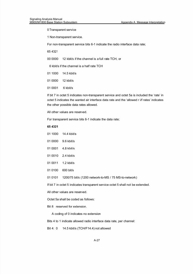
7/30/2019 Signaling Analysis Manual
http://slidepdf.com/reader/full/signaling-analysis-manual 190/290
Signaling Analysis ManualM900/M1800 Base Station Subsystem Appendix A Message Interpretation
A-27
0 Transparent service
1 Non-transparent service.
For non-transparent service bits 6-1 indicate the radio interface data rate;
65 4321
00 0000 12 kbit/s if the channel is a full rate TCH, or
6 kbit/s if the channel is a half rate TCH
01 1000 14.5 kbit/s
01 0000 12 kbit/s
01 0001 6 kbit/s
If bit 7 in octet 5 indicates non-transparent service and octet 5a is included the ‘rate’ in
octet 5 indicates the wanted air interface data rate and the ‘allowed r i/f rates’ indicates
the other possible data rates allowed.
All other values are reserved.
For transparent service bits 6-1 indicate the data rate;
65 4321
01 1000 14.4 kbit/s
01 0000 9.6 kbit/s
01 0001 4.8 kbit/s
01 0010 2.4 kbit/s
01 0011 1.2 kbit/s
01 0100 600 bit/s
01 0101 1200/75 bit/s (1200 network-to-MS / 75 MS-to-network)
If bit 7 in octet 5 indicates transparent service octet 5 shall not be extended.
All other values are reserved.
Octet 5a shall be coded as follows:
Bit 8 reserved for extension.
A coding of 0 indicates no extension
Bits 4 to 1 indicate allowed radio interface data rate, per channel:
Bit 4: 0 14.5 kbit/s (TCH/F14.4) not allowed
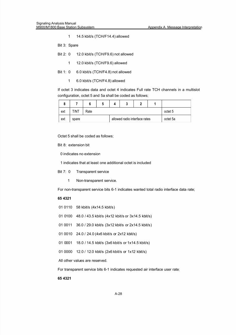
7/30/2019 Signaling Analysis Manual
http://slidepdf.com/reader/full/signaling-analysis-manual 191/290
Signaling Analysis ManualM900/M1800 Base Station Subsystem Appendix A Message Interpretation
A-28
1 14.5 kbit/s (TCH/F14.4) allowed
Bit 3: Spare
Bit 2: 0 12.0 kbit/s (TCH/F9.6) not allowed
1 12.0 kbit/s (TCH/F9.6) allowed
Bit 1: 0 6.0 kbit/s (TCH/F4.8) not allowed
1 6.0 kbit/s (TCH/F4.8) allowed
If octet 3 indicates data and octet 4 indicates Full rate TCH channels in a multislot
configuration, octet 5 and 5a shall be coded as follows;
8 7 6 5 4 3 2 1
ext T/NT Rate octet 5
ext spare allowed radio interface rates octet 5a
Octet 5 shall be coded as follows;
Bit 8: extension bit
0 indicates no extension
1 indicates that at least one additional octet is included
Bit 7: 0 Transparent service
1 Non-transparent service.
For non-transparent service bits 6-1 indicates wanted total radio interface data rate;
65 4321
01 0110 58 kbit/s (4x14.5 kbit/s)
01 0100 48.0 / 43.5 kbit/s (4x12 kbit/s or 3x14.5 kbit/s)
01 0011 36.0 / 29.0 kbit/s (3x12 kbit/s or 2x14.5 kbit/s)
01 0010 24.0 / 24.0 (4x6 kbit/s or 2x12 kbit/s)
01 0001 18.0 / 14.5 kbit/s (3x6 kbit/s or 1x14.5 kbit/s)
01 0000 12.0 / 12.0 kbit/s (2x6 kbit/s or 1x12 kbit/s)
All other values are reserved.
For transparent service bits 6-1 indicates requested air interface user rate;
65 4321
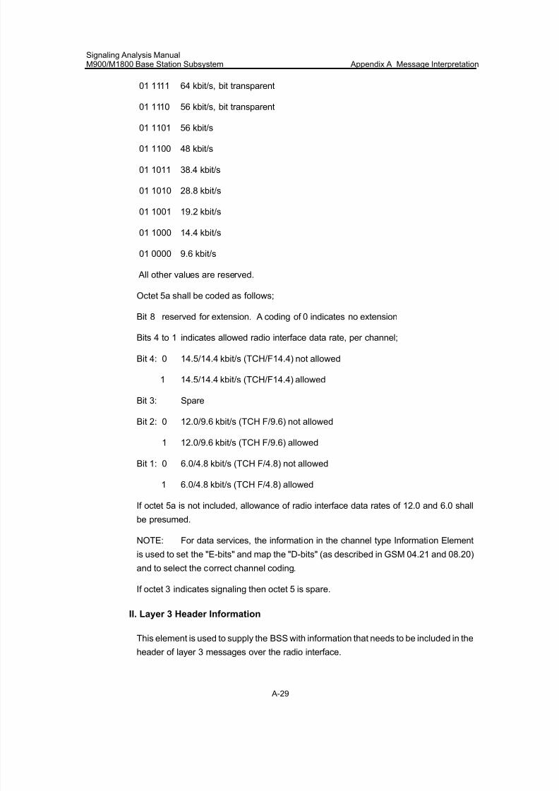
7/30/2019 Signaling Analysis Manual
http://slidepdf.com/reader/full/signaling-analysis-manual 192/290
Signaling Analysis ManualM900/M1800 Base Station Subsystem Appendix A Message Interpretation
A-29
01 1111 64 kbit/s, bit transparent
01 1110 56 kbit/s, bit transparent
01 1101 56 kbit/s
01 1100 48 kbit/s
01 1011 38.4 kbit/s
01 1010 28.8 kbit/s
01 1001 19.2 kbit/s
01 1000 14.4 kbit/s
01 0000 9.6 kbit/s
All other values are reserved.
Octet 5a shall be coded as follows;
Bit 8 reserved for extension. A coding of 0 indicates no extension
Bits 4 to 1 indicates allowed radio interface data rate, per channel;
Bit 4: 0 14.5/14.4 kbit/s (TCH/F14.4) not allowed
1 14.5/14.4 kbit/s (TCH/F14.4) allowed
Bit 3: Spare
Bit 2: 0 12.0/9.6 kbit/s (TCH F/9.6) not allowed
1 12.0/9.6 kbit/s (TCH F/9.6) allowed
Bit 1: 0 6.0/4.8 kbit/s (TCH F/4.8) not allowed
1 6.0/4.8 kbit/s (TCH F/4.8) allowed
If octet 5a is not included, allowance of radio interface data rates of 12.0 and 6.0 shall
be presumed.
NOTE: For data services, the information in the channel type Information Element
is used to set the "E-bits" and map the "D-bits" (as described in GSM 04.21 and 08.20)
and to select the correct channel coding.
If octet 3 indicates signaling then octet 5 is spare.
II. Layer 3 Header Information
This element is used to supply the BSS with information that needs to be included in the
header of layer 3 messages over the radio interface.
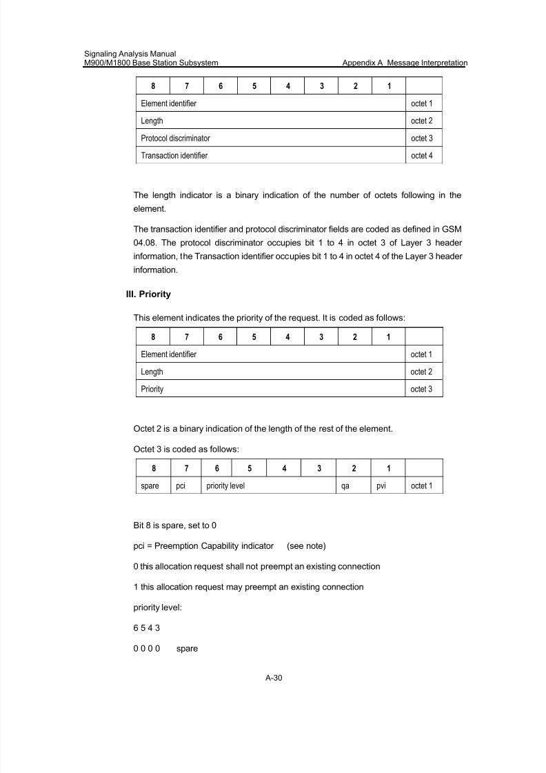
7/30/2019 Signaling Analysis Manual
http://slidepdf.com/reader/full/signaling-analysis-manual 193/290
Signaling Analysis ManualM900/M1800 Base Station Subsystem Appendix A Message Interpretation
A-30
8 7 6 5 4 3 2 1
Element identifier octet 1
Length octet 2
Protocol discriminator octet 3
Transaction identifier octet 4
The length indicator is a binary indication of the number of octets following in the
element.
The transaction identifier and protocol discriminator fields are coded as defined in GSM
04.08. The protocol discriminator occupies bit 1 to 4 in octet 3 of Layer 3 header
information, the Transaction identifier occupies bit 1 to 4 in octet 4 of the Layer 3 header information.
III. Priority
This element indicates the priority of the request. It is coded as follows:
8 7 6 5 4 3 2 1
Element identifier octet 1
Length octet 2
Priority octet 3
Octet 2 is a binary indication of the length of the rest of the element.
Octet 3 is coded as follows:
8 7 6 5 4 3 2 1
spare pci priority level qa pvi octet 1
Bit 8 is spare, set to 0
pci = Preemption Capability indicator (see note)
0 this allocation request shall not preempt an existing connection
1 this allocation request may preempt an existing connection
priority level:
6 5 4 3
0 0 0 0 spare
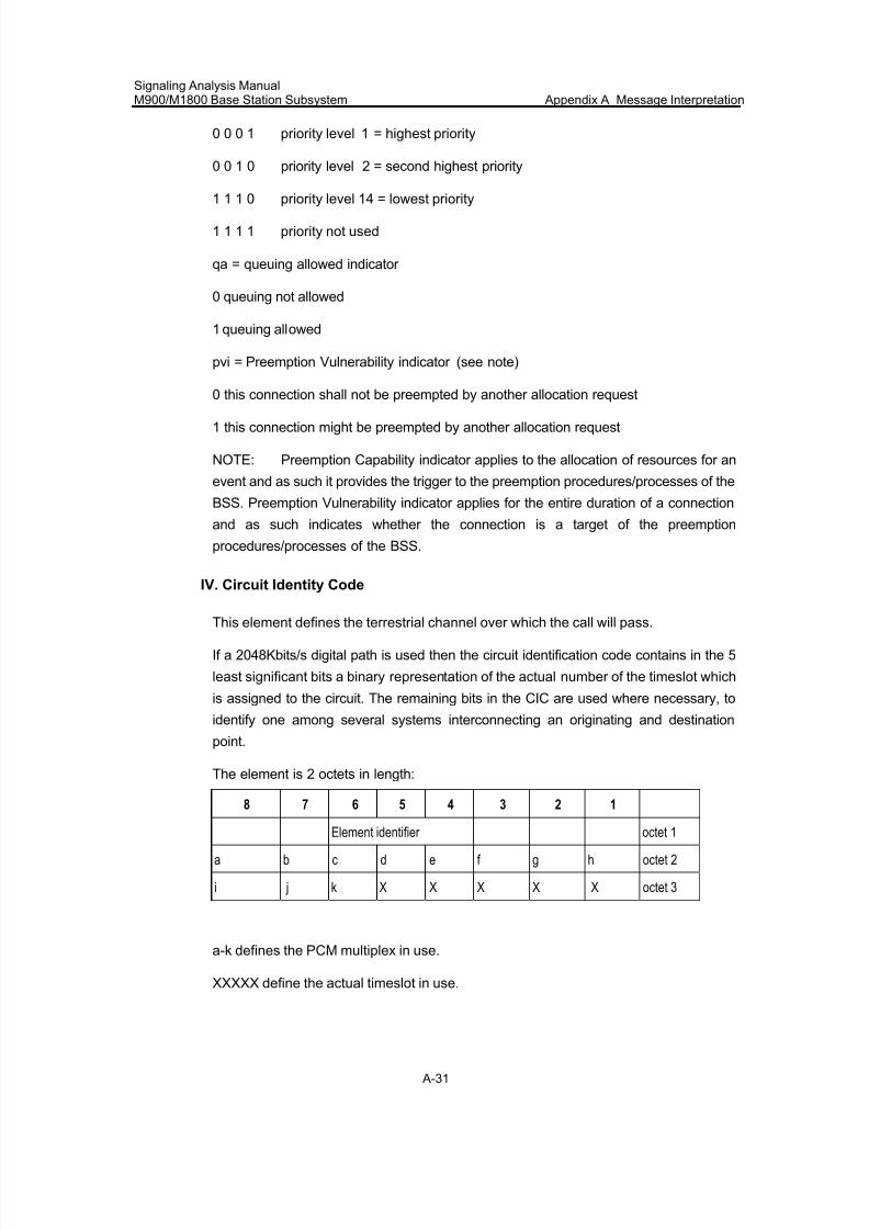
7/30/2019 Signaling Analysis Manual
http://slidepdf.com/reader/full/signaling-analysis-manual 194/290
Signaling Analysis ManualM900/M1800 Base Station Subsystem Appendix A Message Interpretation
A-31
0 0 0 1 priority level 1 = highest priority
0 0 1 0 priority level 2 = second highest priority
1 1 1 0 priority level 14 = lowest priority
1 1 1 1 priority not used
qa = queuing allowed indicator
0 queuing not allowed
1 queuing allowed
pvi = Preemption Vulnerability indicator (see note)
0 this connection shall not be preempted by another allocation request
1 this connection might be preempted by another allocation request
NOTE: Preemption Capability indicator applies to the allocation of resources for an
event and as such it provides the trigger to the preemption procedures/processes of the
BSS. Preemption Vulnerability indicator applies for the entire duration of a connection
and as such indicates whether the connection is a target of the preemption
procedures/processes of the BSS.
IV. Circuit Identity Code
This element defines the terrestrial channel over which the call will pass.
If a 2048Kbits/s digital path is used then the circuit identification code contains in the 5
least significant bits a binary representation of the actual number of the timeslot which
is assigned to the circuit. The remaining bits in the CIC are used where necessary, to
identify one among several systems interconnecting an originating and destination
point.
The element is 2 octets in length:
8 7 6 5 4 3 2 1
Element identifier octet 1
a b c d e f g h octet 2
i j k X X X X X octet 3
a-k defines the PCM multiplex in use.
XXXXX define the actual timeslot in use.
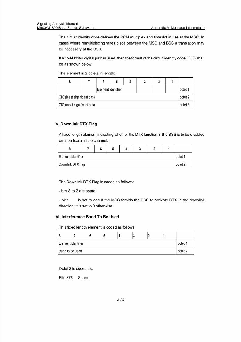
7/30/2019 Signaling Analysis Manual
http://slidepdf.com/reader/full/signaling-analysis-manual 195/290
Signaling Analysis ManualM900/M1800 Base Station Subsystem Appendix A Message Interpretation
A-32
The circuit identity code defines the PCM multiplex and timeslot in use at the MSC. In
cases where remultiplexing takes place between the MSC and BSS a translation may
be necessary at the BSS.
If a 1544 kbit/s digital path is used, then the format of the circuit identity code (CIC) shall
be as shown below:
The element is 2 octets in length:
8 7 6 5 4 3 2 1
Element identifier octet 1
CIC (least significant bits) octet 2
CIC (most significant bits) octet 3
V. Downlink DTX Flag
A fixed length element indicating whether the DTX function in the BSS is to be disabled
on a particular radio channel.
8 7 6 5 4 3 2 1
Element identifier octet 1
Downlink DTX flag octet 2
The Downlink DTX Flag is coded as follows:
- bits 8 to 2 are spare;
- bit 1 is set to one if the MSC forbids the BSS to activate DTX in the downlink
direction; it is set to 0 otherwise.
VI. Interference Band To Be Used
This fixed length element is coded as follows:
8 7 6 5 4 3 2 1
Element identifier octet 1
Band to be used octet 2
Octet 2 is coded as:
Bits 876 Spare
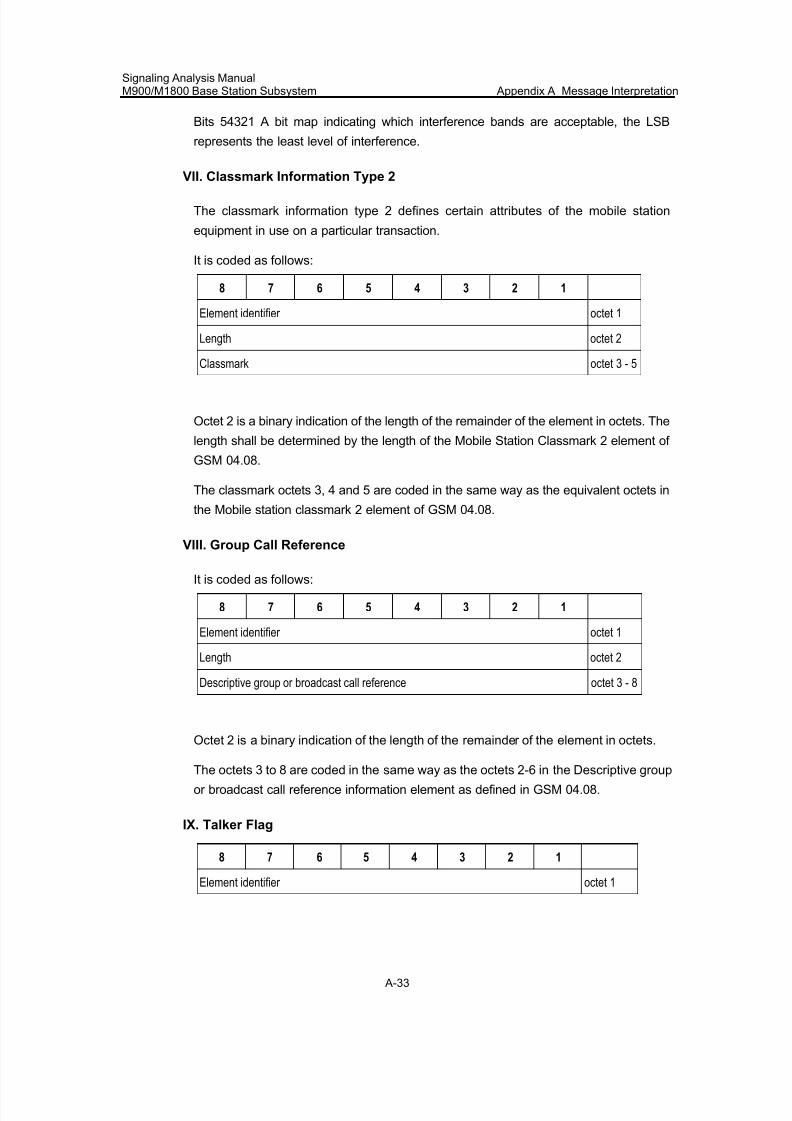
7/30/2019 Signaling Analysis Manual
http://slidepdf.com/reader/full/signaling-analysis-manual 196/290
Signaling Analysis ManualM900/M1800 Base Station Subsystem Appendix A Message Interpretation
A-33
Bits 54321 A bit map indicating which interference bands are acceptable, the LSB
represents the least level of interference.
VII. Classmark Information Type 2
The classmark information type 2 defines certain attributes of the mobile station
equipment in use on a particular transaction.
It is coded as follows:
8 7 6 5 4 3 2 1
Element identifier octet 1
Length octet 2
Classmark octet 3 - 5
Octet 2 is a binary indication of the length of the remainder of the element in octets. The
length shall be determined by the length of the Mobile Station Classmark 2 element of
GSM 04.08.
The classmark octets 3, 4 and 5 are coded in the same way as the equivalent octets in
the Mobile station classmark 2 element of GSM 04.08.
VIII. Group Call Reference
It is coded as follows:
8 7 6 5 4 3 2 1
Element identifier octet 1
Length octet 2
Descriptive group or broadcast call reference octet 3 - 8
Octet 2 is a binary indication of the length of the remainder of the element in octets.
The octets 3 to 8 are coded in the same way as the octets 2-6 in the Descriptive group
or broadcast call reference information element as defined in GSM 04.08.
IX. Talker Flag
8 7 6 5 4 3 2 1
Element identifier octet 1
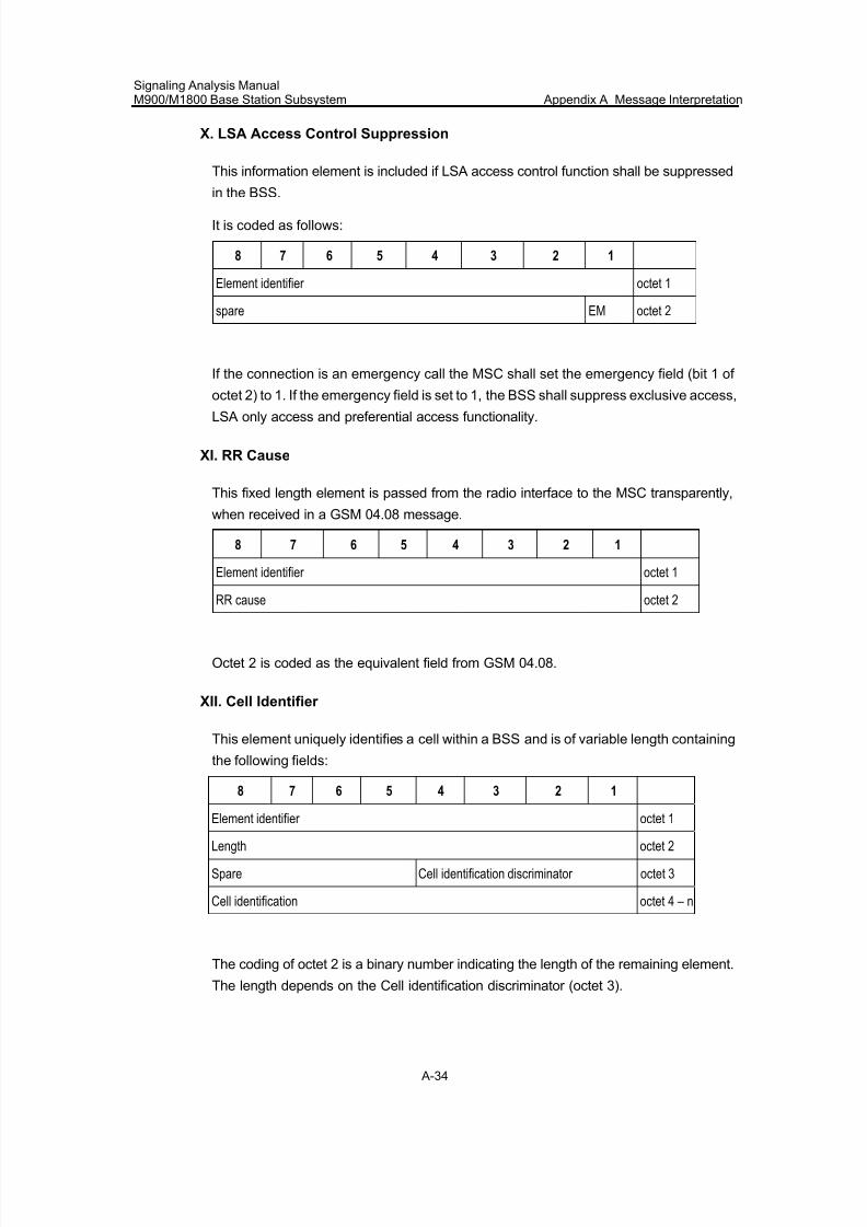
7/30/2019 Signaling Analysis Manual
http://slidepdf.com/reader/full/signaling-analysis-manual 197/290
Signaling Analysis ManualM900/M1800 Base Station Subsystem Appendix A Message Interpretation
A-34
X. LSA Access Control Suppression
This information element is included if LSA access control function shall be suppressed
in the BSS.
It is coded as follows:
8 7 6 5 4 3 2 1
Element identifier octet 1
spare EM octet 2
If the connection is an emergency call the MSC shall set the emergency field (bit 1 of
octet 2) to 1. If the emergency field is set to 1, the BSS shall suppress exclusive access,
LSA only access and preferential access functionality.
XI. RR Cause
This fixed length element is passed from the radio interface to the MSC transparently,
when received in a GSM 04.08 message.
8 7 6 5 4 3 2 1
Element identifier octet 1
RR cause octet 2
Octet 2 is coded as the equivalent field from GSM 04.08.
XII. Cell Identifier
This element uniquely identifies a cell within a BSS and is of variable length containing
the following fields:
8 7 6 5 4 3 2 1
Element identifier octet 1
Length octet 2
Spare Cell identification discriminator octet 3
Cell identification octet 4 – n
The coding of octet 2 is a binary number indicating the length of the remaining element.
The length depends on the Cell identification discriminator (octet 3).
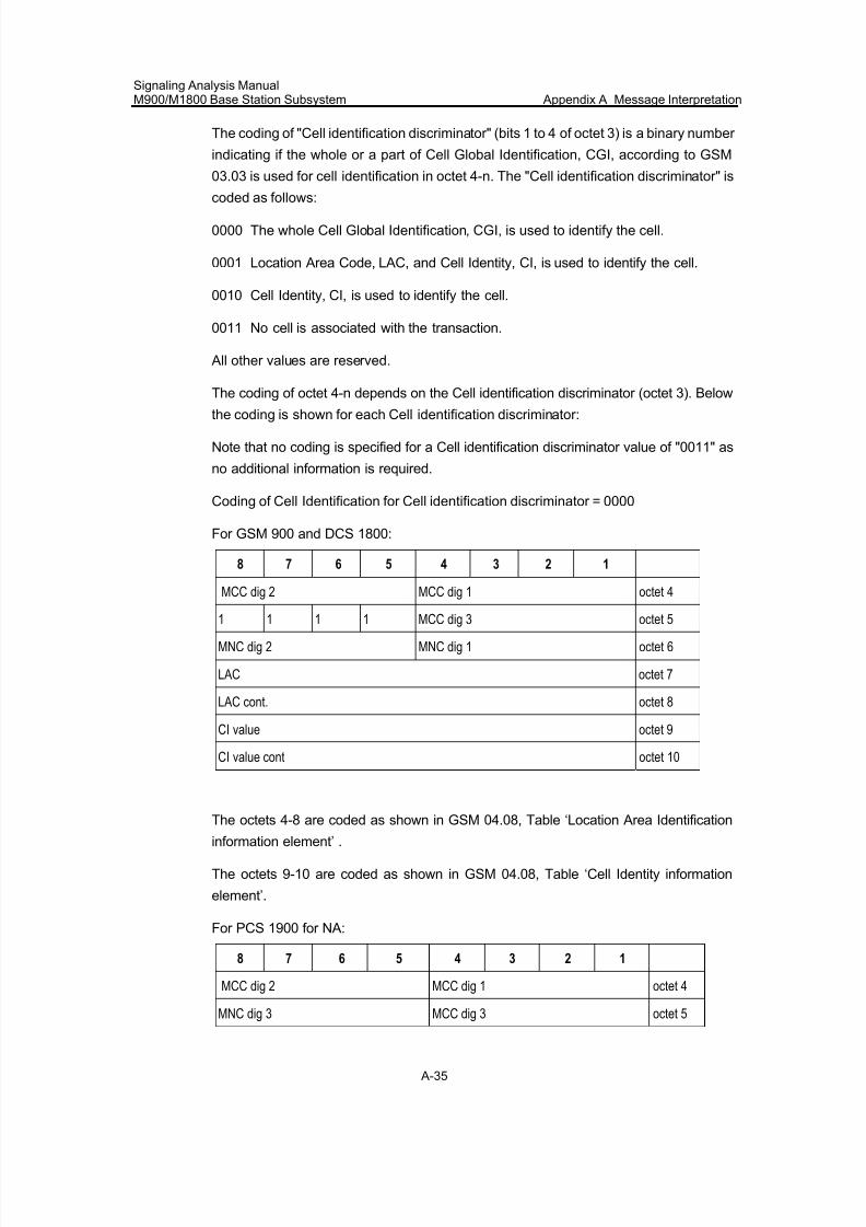
7/30/2019 Signaling Analysis Manual
http://slidepdf.com/reader/full/signaling-analysis-manual 198/290
Signaling Analysis ManualM900/M1800 Base Station Subsystem Appendix A Message Interpretation
A-35
The coding of "Cell identification discriminator" (bits 1 to 4 of octet 3) is a binary number
indicating if the whole or a part of Cell Global Identification, CGI, according to GSM
03.03 is used for cell identification in octet 4-n. The "Cell identification discriminator" is
coded as follows:
0000 The whole Cell Global Identification, CGI, is used to identify the cell.
0001 Location Area Code, LAC, and Cell Identity, CI, is used to identify the cell.
0010 Cell Identity, CI, is used to identify the cell.
0011 No cell is associated with the transaction.
All other values are reserved.
The coding of octet 4-n depends on the Cell identification discriminator (octet 3). Below
the coding is shown for each Cell identification discriminator:
Note that no coding is specified for a Cell identification discriminator value of "0011" as
no additional information is required.
Coding of Cell Identification for Cell identification discriminator = 0000
For GSM 900 and DCS 1800:
8 7 6 5 4 3 2 1
MCC dig 2 MCC dig 1 octet 4
1 1 1 1 MCC dig 3 octet 5
MNC dig 2 MNC dig 1 octet 6
LAC octet 7
LAC cont. octet 8
CI value octet 9
CI value cont octet 10
The octets 4-8 are coded as shown in GSM 04.08, Table ‘Location Area Identification
information element’ .
The octets 9-10 are coded as shown in GSM 04.08, Table ‘Cell Identity information
element’.
For PCS 1900 for NA:
8 7 6 5 4 3 2 1
MCC dig 2 MCC dig 1 octet 4
MNC dig 3 MCC dig 3 octet 5
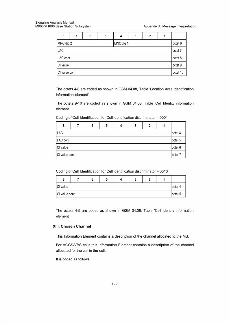
7/30/2019 Signaling Analysis Manual
http://slidepdf.com/reader/full/signaling-analysis-manual 199/290
Signaling Analysis ManualM900/M1800 Base Station Subsystem Appendix A Message Interpretation
A-36
8 7 6 5 4 3 2 1
MNC dig 2 MNC dig 1 octet 6
LAC octet 7
LAC cont. octet 8
CI value octet 9
CI value cont octet 10
The octets 4-8 are coded as shown in GSM 04.08, Table ‘Location Area Identification
information element’.
The octets 9-10 are coded as shown in GSM 04.08, Table ‘Cell Identity information
element’.
Coding of Cell Identification for Cell identification discriminator = 0001
8 7 6 5 4 3 2 1
LAC octet 4
LAC cont. octet 5
CI value octet 6
CI value cont octet 7
Coding of Cell Identification for Cell identification discriminator = 0010
8 7 6 5 4 3 2 1
CI value octet 4
CI value cont octet 5
The octets 4-5 are coded as shown in GSM 04.08, Table ‘Cell Identity information
element’
XIII. Chosen Channel
This Information Element contains a description of the channel allocated to the MS.
For VGCS/VBS calls this Information Element contains a description of the channel
allocated for the call in the cell.
It is coded as follows:
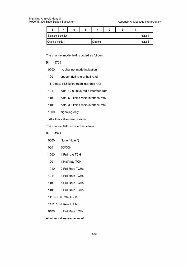
7/30/2019 Signaling Analysis Manual
http://slidepdf.com/reader/full/signaling-analysis-manual 200/290
Signaling Analysis ManualM900/M1800 Base Station Subsystem Appendix A Message Interpretation
A-37
8 7 6 5 4 3 2 1
Element identifier octet 1
Channel mode Channel octet 2
The channel mode field is coded as follows:
Bit 8765
0000 no channel mode indication
1001 speech (full rate or half rate)
1110 data, 14.5 kbit/s radio interface rate
1011 data, 12.0 kbit/s radio interface rate
1100 data, 6.0 kbit/s radio interface rate
1101 data, 3.6 kbit/s radio interface rate
1000 signaling only
All other values are reserved.
The channel field is coded as follows:
Bit 4321
0000 None (Note *)
0001 SDCCH
1000 1 Full rate TCH
1001 1 Half rate TCH
1010 2 Full Rate TCHs
1011 3 Full Rate TCHs
1100 4 Full Rate TCHs
1101 5 Full Rate TCHs
1110 6 Full Rate TCHs
1111 7 Full Rate TCHs
0100 8 Full Rate TCHs
All other values are reserved.
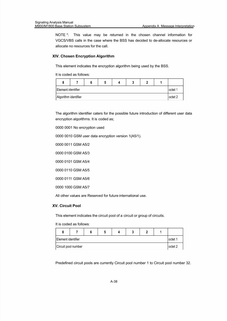
7/30/2019 Signaling Analysis Manual
http://slidepdf.com/reader/full/signaling-analysis-manual 201/290
Signaling Analysis ManualM900/M1800 Base Station Subsystem Appendix A Message Interpretation
A-38
NOTE *: This value may be returned in the chosen channel information for
VGCS/VBS calls in the case where the BSS has decided to de-allocate resources or
allocate no resources for the call.
XIV. Chosen Encryption Algorithm
This element indicates the encryption algorithm being used by the BSS.
It is coded as follows:
8 7 6 5 4 3 2 1
Element identifier octet 1
Algorithm identifier octet 2
The algorithm identifier caters for the possible future introduction of different user data
encryption algorithms. It is coded as;
0000 0001 No encryption used
0000 0010 GSM user data encryption version 1(A5/1).
0000 0011 GSM A5/2
0000 0100 GSM A5/3
0000 0101 GSM A5/4
0000 0110 GSM A5/5
0000 0111 GSM A5/6
0000 1000 GSM A5/7
All other values are Reserved for future international use.
XV. Circuit Pool
This element indicates the circuit pool of a circuit or group of circuits.
It is coded as follows:
8 7 6 5 4 3 2 1
Element identifier octet 1
Circuit pool number octet 2
Predefined circuit pools are currently Circuit pool number 1 to Circuit pool number 32.
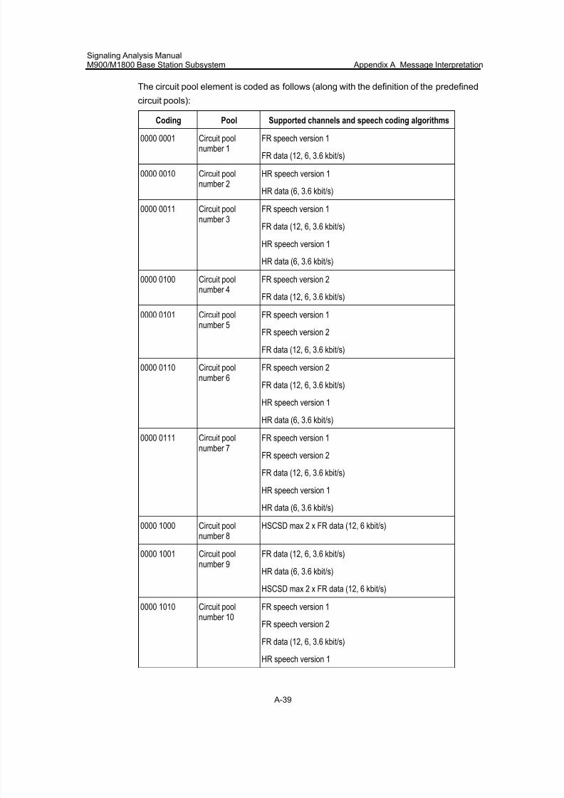
7/30/2019 Signaling Analysis Manual
http://slidepdf.com/reader/full/signaling-analysis-manual 202/290
Signaling Analysis ManualM900/M1800 Base Station Subsystem Appendix A Message Interpretation
A-39
The circuit pool element is coded as follows (along with the definition of the predefined
circuit pools):
Coding Pool Supported channels and speech coding algorithms
0000 0001 Circuit poolnumber 1
FR speech version 1
FR data (12, 6, 3.6 kbit/s)
0000 0010 Circuit poolnumber 2
HR speech version 1
HR data (6, 3.6 kbit/s)
0000 0011 Circuit poolnumber 3
FR speech version 1
FR data (12, 6, 3.6 kbit/s)
HR speech version 1
HR data (6, 3.6 kbit/s)
0000 0100 Circuit poolnumber 4
FR speech version 2
FR data (12, 6, 3.6 kbit/s)
0000 0101 Circuit poolnumber 5
FR speech version 1
FR speech version 2
FR data (12, 6, 3.6 kbit/s)
0000 0110 Circuit poolnumber 6
FR speech version 2
FR data (12, 6, 3.6 kbit/s)
HR speech version 1
HR data (6, 3.6 kbit/s)
0000 0111 Circuit poolnumber 7
FR speech version 1
FR speech version 2
FR data (12, 6, 3.6 kbit/s)
HR speech version 1
HR data (6, 3.6 kbit/s)
0000 1000 Circuit pool
number 8
HSCSD max 2 x FR data (12, 6 kbit/s)
0000 1001 Circuit poolnumber 9
FR data (12, 6, 3.6 kbit/s)
HR data (6, 3.6 kbit/s)
HSCSD max 2 x FR data (12, 6 kbit/s)
0000 1010 Circuit poolnumber 10
FR speech version 1
FR speech version 2
FR data (12, 6, 3.6 kbit/s)
HR speech version 1
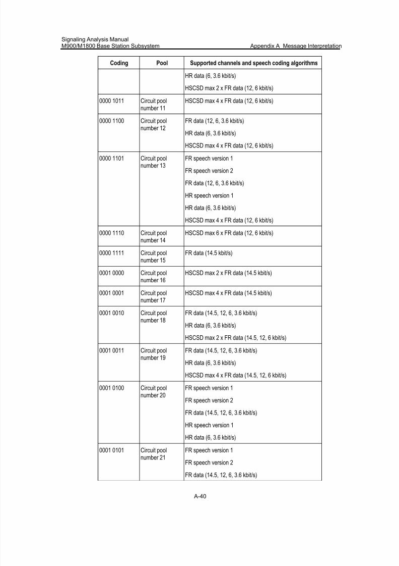
7/30/2019 Signaling Analysis Manual
http://slidepdf.com/reader/full/signaling-analysis-manual 203/290
Signaling Analysis ManualM900/M1800 Base Station Subsystem Appendix A Message Interpretation
A-40
Coding Pool Supported channels and speech coding algorithms
HR data (6, 3.6 kbit/s)
HSCSD max 2 x FR data (12, 6 kbit/s)
0000 1011 Circuit poolnumber 11
HSCSD max 4 x FR data (12, 6 kbit/s)
0000 1100 Circuit poolnumber 12
FR data (12, 6, 3.6 kbit/s)
HR data (6, 3.6 kbit/s)
HSCSD max 4 x FR data (12, 6 kbit/s)
0000 1101 Circuit poolnumber 13
FR speech version 1
FR speech version 2
FR data (12, 6, 3.6 kbit/s)
HR speech version 1
HR data (6, 3.6 kbit/s)
HSCSD max 4 x FR data (12, 6 kbit/s)
0000 1110 Circuit poolnumber 14
HSCSD max 6 x FR data (12, 6 kbit/s)
0000 1111 Circuit poolnumber 15
FR data (14.5 kbit/s)
0001 0000 Circuit pool
number 16
HSCSD max 2 x FR data (14.5 kbit/s)
0001 0001 Circuit poolnumber 17
HSCSD max 4 x FR data (14.5 kbit/s)
0001 0010 Circuit poolnumber 18
FR data (14.5, 12, 6, 3.6 kbit/s)
HR data (6, 3.6 kbit/s)
HSCSD max 2 x FR data (14.5, 12, 6 kbit/s)
0001 0011 Circuit poolnumber 19
FR data (14.5, 12, 6, 3.6 kbit/s)
HR data (6, 3.6 kbit/s)
HSCSD max 4 x FR data (14.5, 12, 6 kbit/s)0001 0100 Circuit pool
number 20FR speech version 1
FR speech version 2
FR data (14.5, 12, 6, 3.6 kbit/s)
HR speech version 1
HR data (6, 3.6 kbit/s)
0001 0101 Circuit poolnumber 21
FR speech version 1
FR speech version 2
FR data (14.5, 12, 6, 3.6 kbit/s)
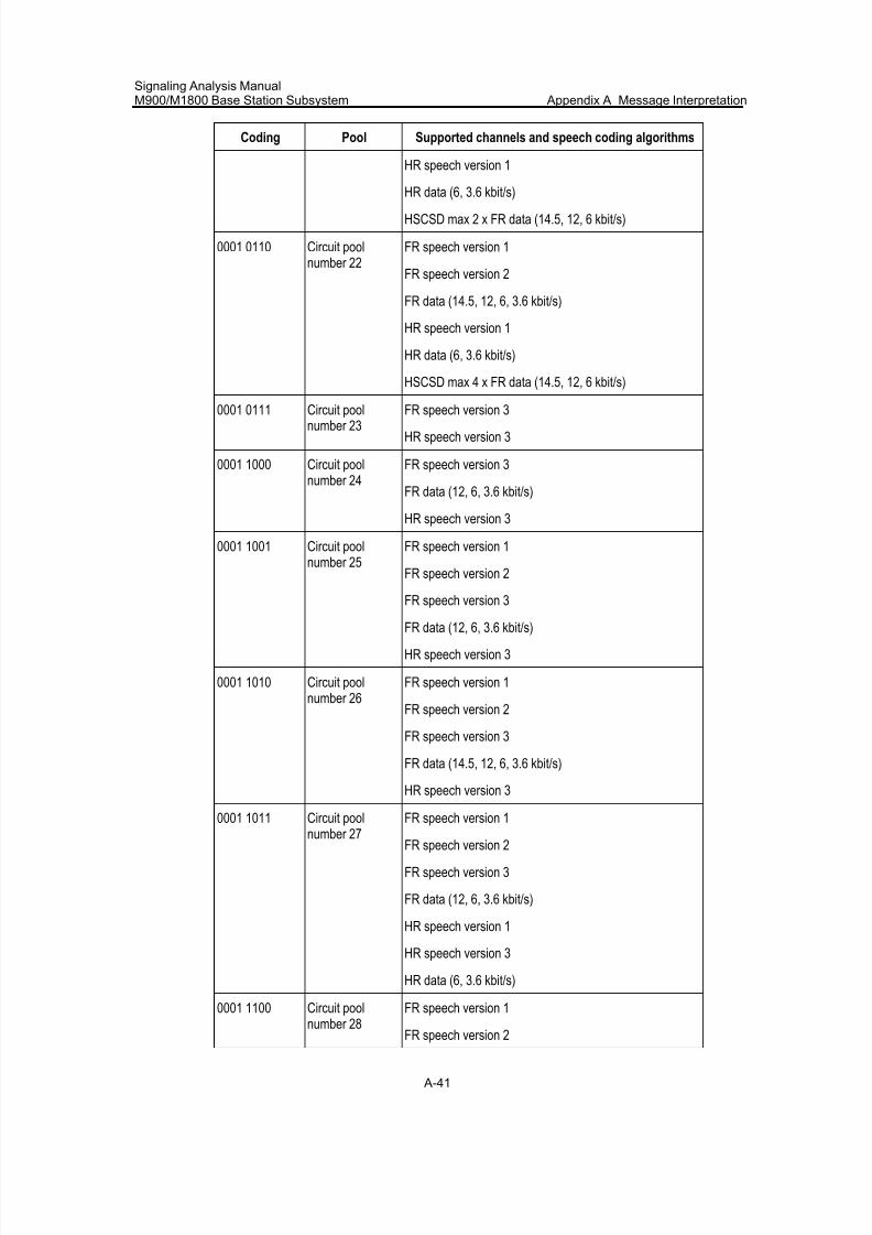
7/30/2019 Signaling Analysis Manual
http://slidepdf.com/reader/full/signaling-analysis-manual 204/290
Signaling Analysis ManualM900/M1800 Base Station Subsystem Appendix A Message Interpretation
A-41
Coding Pool Supported channels and speech coding algorithms
HR speech version 1
HR data (6, 3.6 kbit/s)
HSCSD max 2 x FR data (14.5, 12, 6 kbit/s)
0001 0110 Circuit poolnumber 22
FR speech version 1
FR speech version 2
FR data (14.5, 12, 6, 3.6 kbit/s)
HR speech version 1
HR data (6, 3.6 kbit/s)
HSCSD max 4 x FR data (14.5, 12, 6 kbit/s)
0001 0111 Circuit poolnumber 23
FR speech version 3
HR speech version 3
0001 1000 Circuit poolnumber 24
FR speech version 3
FR data (12, 6, 3.6 kbit/s)
HR speech version 3
0001 1001 Circuit poolnumber 25
FR speech version 1
FR speech version 2
FR speech version 3
FR data (12, 6, 3.6 kbit/s)
HR speech version 3
0001 1010 Circuit poolnumber 26
FR speech version 1
FR speech version 2
FR speech version 3
FR data (14.5, 12, 6, 3.6 kbit/s)
HR speech version 3
0001 1011 Circuit poolnumber 27 FR speech version 1FR speech version 2
FR speech version 3
FR data (12, 6, 3.6 kbit/s)
HR speech version 1
HR speech version 3
HR data (6, 3.6 kbit/s)
0001 1100 Circuit pool
number 28
FR speech version 1
FR speech version 2
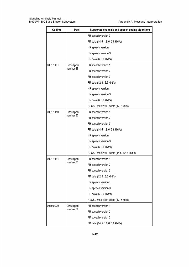
7/30/2019 Signaling Analysis Manual
http://slidepdf.com/reader/full/signaling-analysis-manual 205/290
Signaling Analysis ManualM900/M1800 Base Station Subsystem Appendix A Message Interpretation
A-42
Coding Pool Supported channels and speech coding algorithms
FR speech version 3
FR data (14.5, 12, 6, 3.6 kbit/s)
HR speech version 1
HR speech version 3
HR data (6, 3.6 kbit/s)
0001 1101 Circuit poolnumber 29
FR speech version 1
FR speech version 2
FR speech version 3
FR data (12, 6, 3.6 kbit/s)
HR speech version 1
HR speech version 3
HR data (6, 3.6 kbit/s)
HSCSD max 2 x FR data (12, 6 kbit/s)
0001 1110 Circuit poolnumber 30
FR speech version 1
FR speech version 2
FR speech version 3
FR data (14.5, 12, 6, 3.6 kbit/s)
HR speech version 1
HR speech version 3
HR data (6, 3.6 kbit/s)
HSCSD max 2 x FR data (14.5, 12, 6 kbit/s)
0001 1111 Circuit poolnumber 31
FR speech version 1
FR speech version 2
FR speech version 3
FR data (12, 6, 3.6 kbit/s)
HR speech version 1
HR speech version 3
HR data (6, 3.6 kbit/s)
HSCSD max 4 x FR data (12, 6 kbit/s)
0010 0000 Circuit poolnumber 32
FR speech version 1
FR speech version 2
FR speech version 3
FR data (14.5, 12, 6, 3.6 kbit/s)
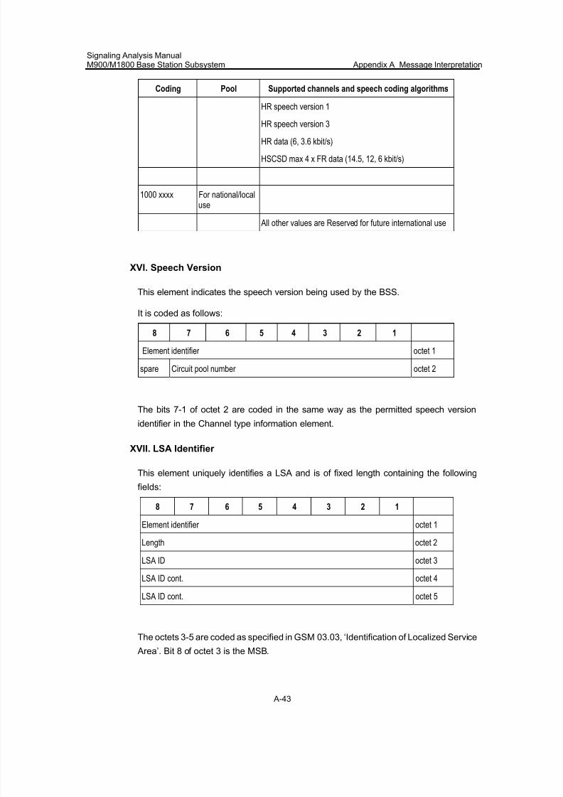
7/30/2019 Signaling Analysis Manual
http://slidepdf.com/reader/full/signaling-analysis-manual 206/290
Signaling Analysis ManualM900/M1800 Base Station Subsystem Appendix A Message Interpretation
A-43
Coding Pool Supported channels and speech coding algorithms
HR speech version 1
HR speech version 3
HR data (6, 3.6 kbit/s)
HSCSD max 4 x FR data (14.5, 12, 6 kbit/s)
1000 xxxx For national/localuse
All other values are Reserved for future international use
XVI. Speech Version
This element indicates the speech version being used by the BSS.
It is coded as follows:
8 7 6 5 4 3 2 1
Element identifier octet 1
spare Circuit pool number octet 2
The bits 7-1 of octet 2 are coded in the same way as the permitted speech version
identifier in the Channel type information element.
XVII. LSA Identifier
This element uniquely identifies a LSA and is of fixed length containing the following
fields:
8 7 6 5 4 3 2 1
Element identifier octet 1
Length octet 2
LSA ID octet 3
LSA ID cont. octet 4
LSA ID cont. octet 5
The octets 3-5 are coded as specified in GSM 03.03, ‘Identification of Localized Service
Area’. Bit 8 of octet 3 is the MSB.
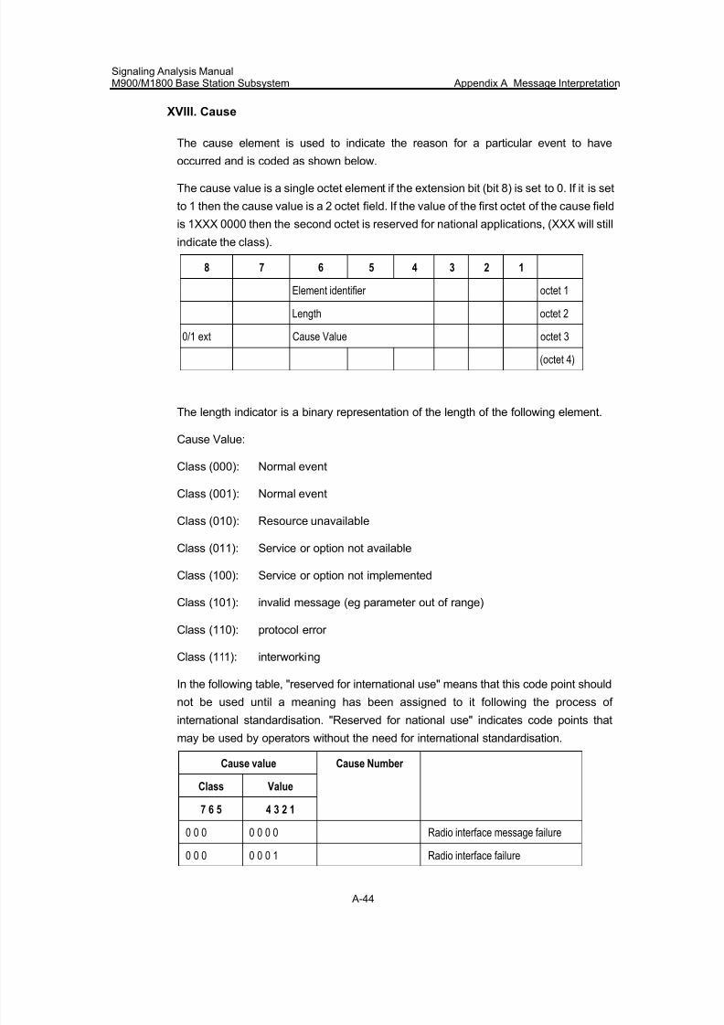
7/30/2019 Signaling Analysis Manual
http://slidepdf.com/reader/full/signaling-analysis-manual 207/290
Signaling Analysis ManualM900/M1800 Base Station Subsystem Appendix A Message Interpretation
A-44
XVIII. Cause
The cause element is used to indicate the reason for a particular event to have
occurred and is coded as shown below.
The cause value is a single octet element if the extension bit (bit 8) is set to 0. If it is set
to 1 then the cause value is a 2 octet field. If the value of the first octet of the cause field
is 1XXX 0000 then the second octet is reserved for national applications, (XXX will still
indicate the class).
8 7 6 5 4 3 2 1
Element identifier octet 1
Length octet 2
0/1 ext Cause Value octet 3(octet 4)
The length indicator is a binary representation of the length of the following element.
Cause Value:
Class (000): Normal event
Class (001): Normal event
Class (010): Resource unavailable
Class (011): Service or option not available
Class (100): Service or option not implemented
Class (101): invalid message (eg parameter out of range)
Class (110): protocol error
Class (111): interworking
In the following table, "reserved for international use" means that this code point shouldnot be used until a meaning has been assigned to it following the process of
international standardisation. "Reserved for national use" indicates code points that
may be used by operators without the need for international standardisation.
Cause value
Class Value
7 6 5 4 3 2 1
Cause Number
0 0 0 0 0 0 0 Radio interface message failure
0 0 0 0 0 0 1 Radio interface failure
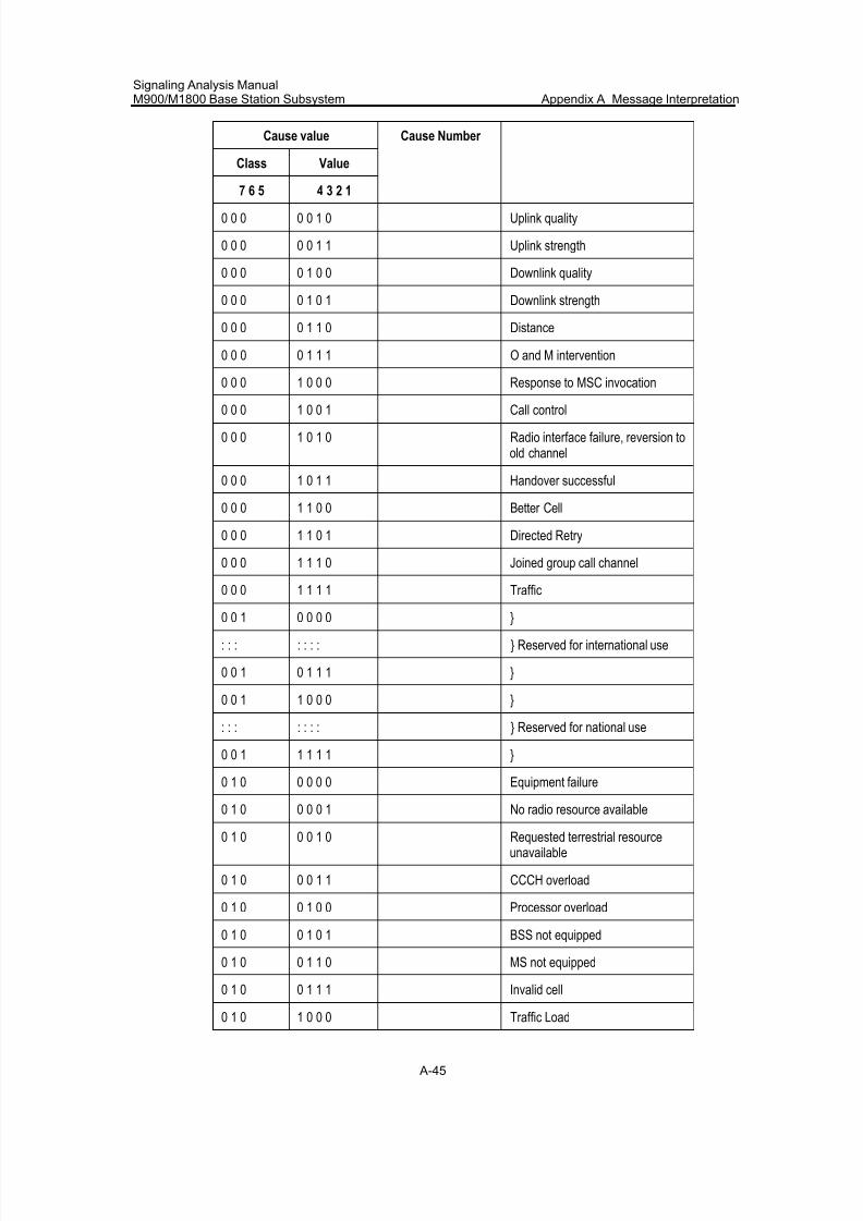
7/30/2019 Signaling Analysis Manual
http://slidepdf.com/reader/full/signaling-analysis-manual 208/290
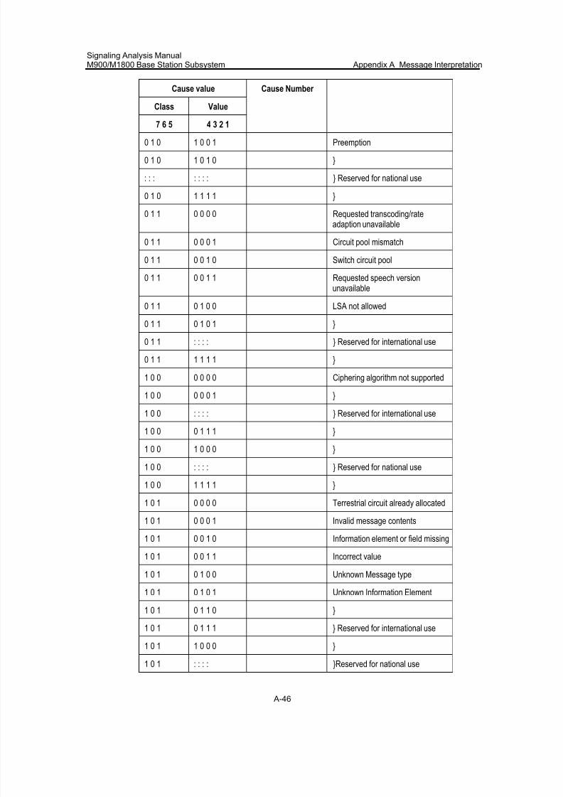
7/30/2019 Signaling Analysis Manual
http://slidepdf.com/reader/full/signaling-analysis-manual 209/290
Signaling Analysis ManualM900/M1800 Base Station Subsystem Appendix A Message Interpretation
A-46
Cause value
Class Value
7 6 5 4 3 2 1
Cause Number
0 1 0 1 0 0 1 Preemption
0 1 0 1 0 1 0 }
: : : : : : : } Reserved for national use
0 1 0 1 1 1 1 }
0 1 1 0 0 0 0 Requested transcoding/rateadaption unavailable
0 1 1 0 0 0 1 Circuit pool mismatch
0 1 1 0 0 1 0 Switch circuit pool
0 1 1 0 0 1 1 Requested speech versionunavailable
0 1 1 0 1 0 0 LSA not allowed
0 1 1 0 1 0 1 }
0 1 1 : : : : } Reserved for international use
0 1 1 1 1 1 1 }
1 0 0 0 0 0 0 Ciphering algorithm not supported
1 0 0 0 0 0 1 }
1 0 0 : : : : } Reserved for international use
1 0 0 0 1 1 1 }
1 0 0 1 0 0 0 }
1 0 0 : : : : } Reserved for national use
1 0 0 1 1 1 1 }
1 0 1 0 0 0 0 Terrestrial circuit already allocated
1 0 1 0 0 0 1 Invalid message contents
1 0 1 0 0 1 0 Information element or field missing
1 0 1 0 0 1 1 Incorrect value
1 0 1 0 1 0 0 Unknown Message type
1 0 1 0 1 0 1 Unknown Information Element
1 0 1 0 1 1 0 }
1 0 1 0 1 1 1 } Reserved for international use
1 0 1 1 0 0 0 }
1 0 1 : : : : }Reserved for national use
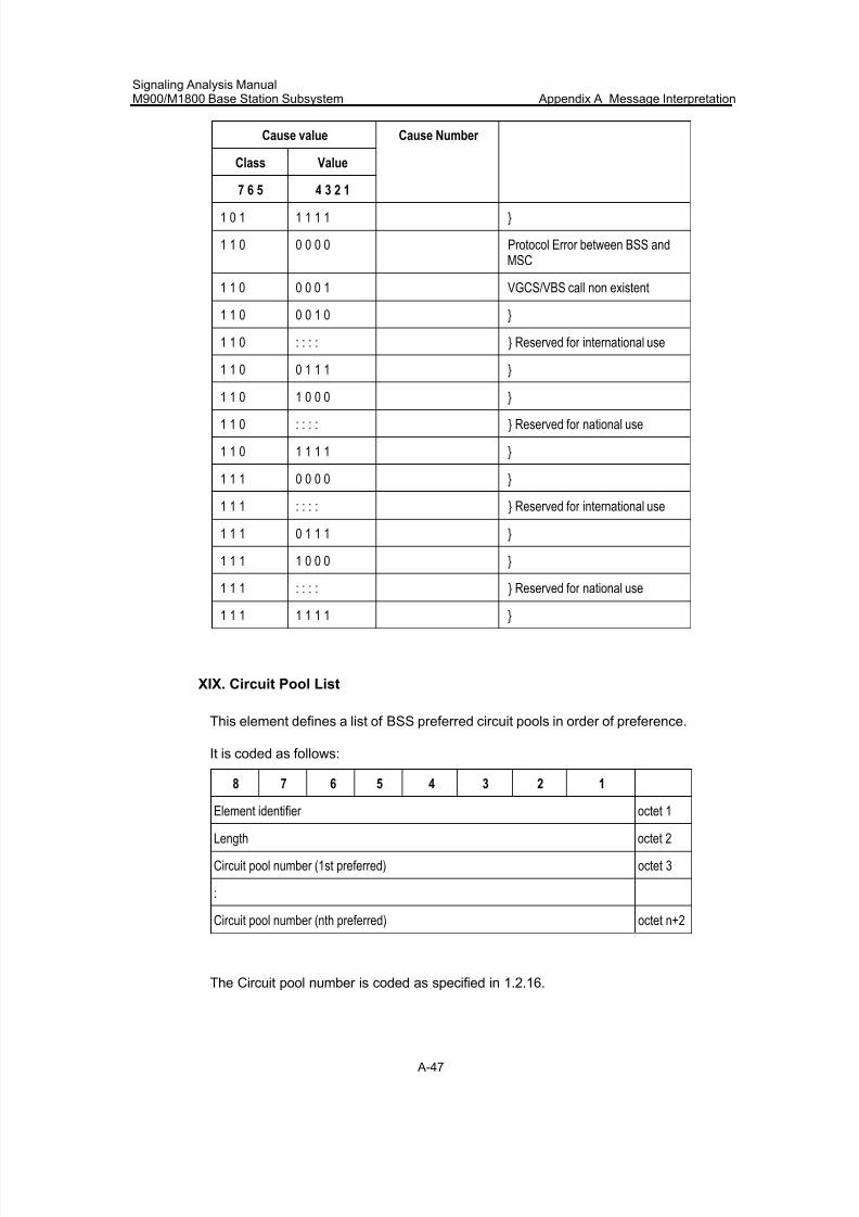
7/30/2019 Signaling Analysis Manual
http://slidepdf.com/reader/full/signaling-analysis-manual 210/290
Signaling Analysis ManualM900/M1800 Base Station Subsystem Appendix A Message Interpretation
A-47
Cause value
Class Value
7 6 5 4 3 2 1
Cause Number
1 0 1 1 1 1 1 }
1 1 0 0 0 0 0 Protocol Error between BSS andMSC
1 1 0 0 0 0 1 VGCS/VBS call non existent
1 1 0 0 0 1 0 }
1 1 0 : : : : } Reserved for international use
1 1 0 0 1 1 1 }
1 1 0 1 0 0 0 }
1 1 0 : : : : } Reserved for national use
1 1 0 1 1 1 1 }
1 1 1 0 0 0 0 }
1 1 1 : : : : } Reserved for international use
1 1 1 0 1 1 1 }
1 1 1 1 0 0 0 }
1 1 1 : : : : } Reserved for national use
1 1 1 1 1 1 1 }
XIX. Circuit Pool List
This element defines a list of BSS preferred circuit pools in order of preference.
It is coded as follows:
8 7 6 5 4 3 2 1
Element identifier octet 1
Length octet 2
Circuit pool number (1st preferred) octet 3
:
Circuit pool number (nth preferred) octet n+2
The Circuit pool number is coded as specified in 1.2.16.
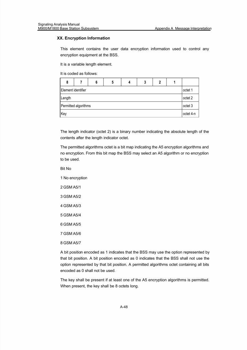
7/30/2019 Signaling Analysis Manual
http://slidepdf.com/reader/full/signaling-analysis-manual 211/290
Signaling Analysis ManualM900/M1800 Base Station Subsystem Appendix A Message Interpretation
A-48
XX. Encryption Information
This element contains the user data encryption information used to control any
encryption equipment at the BSS.
It is a variable length element.
It is coded as follows:
8 7 6 5 4 3 2 1
Element identifier octet 1
Length octet 2
Permitted algorithms octet 3
Key octet 4-n
The length indicator (octet 2) is a binary number indicating the absolute length of the
contents after the length indicator octet.
The permitted algorithms octet is a bit map indicating the A5 encryption algorithms and
no encryption. From this bit map the BSS may select an A5 algorithm or no encryption
to be used.
Bit No
1 No encryption
2 GSM A5/1
3 GSM A5/2
4 GSM A5/3
5 GSM A5/4
6 GSM A5/5
7 GSM A5/6
8 GSM A5/7
A bit position encoded as 1 indicates that the BSS may use the option represented by
that bit position. A bit position encoded as 0 indicates that the BSS shall not use the
option represented by that bit position. A permitted algorithms octet containing all bits
encoded as 0 shall not be used.
The key shall be present if at least one of the A5 encryption algorithms is permitted.
When present, the key shall be 8 octets long.
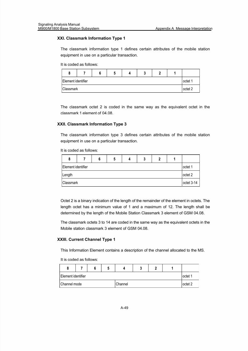
7/30/2019 Signaling Analysis Manual
http://slidepdf.com/reader/full/signaling-analysis-manual 212/290
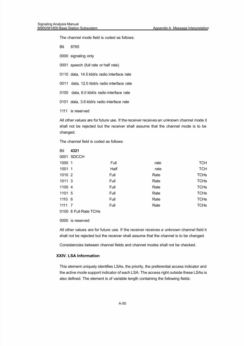
7/30/2019 Signaling Analysis Manual
http://slidepdf.com/reader/full/signaling-analysis-manual 213/290
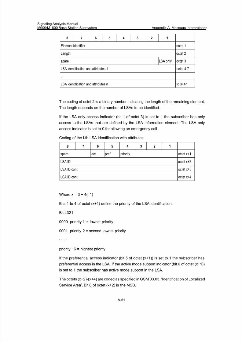
7/30/2019 Signaling Analysis Manual
http://slidepdf.com/reader/full/signaling-analysis-manual 214/290
Signaling Analysis ManualM900/M1800 Base Station Subsystem Appendix A Message Interpretation
A-51
8 7 6 5 4 3 2 1
Element identifier octet 1
Length octet 2
spare LSA only octet 3
LSA identification and attributes 1 octet 4-7
:
LSA identification and attributes n to 3+4n
The coding of octet 2 is a binary number indicating the length of the remaining element.
The length depends on the number of LSAs to be identified.
If the LSA only access indicator (bit 1 of octet 3) is set to 1 the subscriber has only
access to the LSAs that are defined by the LSA Information element. The LSA only
access indicator is set to 0 for allowing an emergency call.
Coding of the i-th LSA identification with attributes:
8 7 6 5 4 3 2 1
spare act pref priority octet x+1
LSA ID octet x+2
LSA ID cont. octet x+3LSA ID cont. octet x+4
Where x = 3 + 4(i-1)
Bits 1 to 4 of octet (x+1) define the priority of the LSA identification.
Bit 4321
0000 priority 1 = lowest priority
0001 priority 2 = second lowest priority
: : : :
priority 16 = highest priority
If the preferential access indicator (bit 5 of octet (x+1)) is set to 1 the subscriber has
preferential access in the LSA. If the active mode support indicator (bit 6 of octet (x+1))
is set to 1 the subscriber has active mode support in the LSA.
The octets (x+2)-(x+4) are coded as specified in GSM 03.03, ‘Identification of Localized
Service Area’. Bit 8 of octet (x+2) is the MSB.
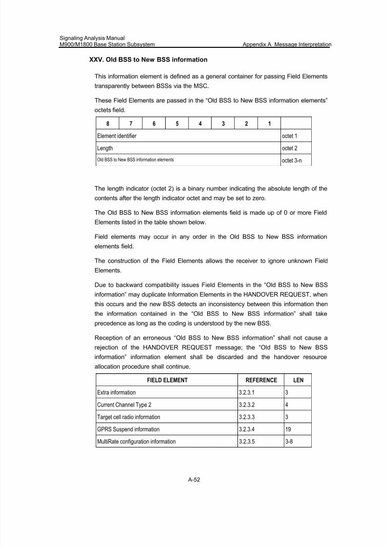
7/30/2019 Signaling Analysis Manual
http://slidepdf.com/reader/full/signaling-analysis-manual 215/290
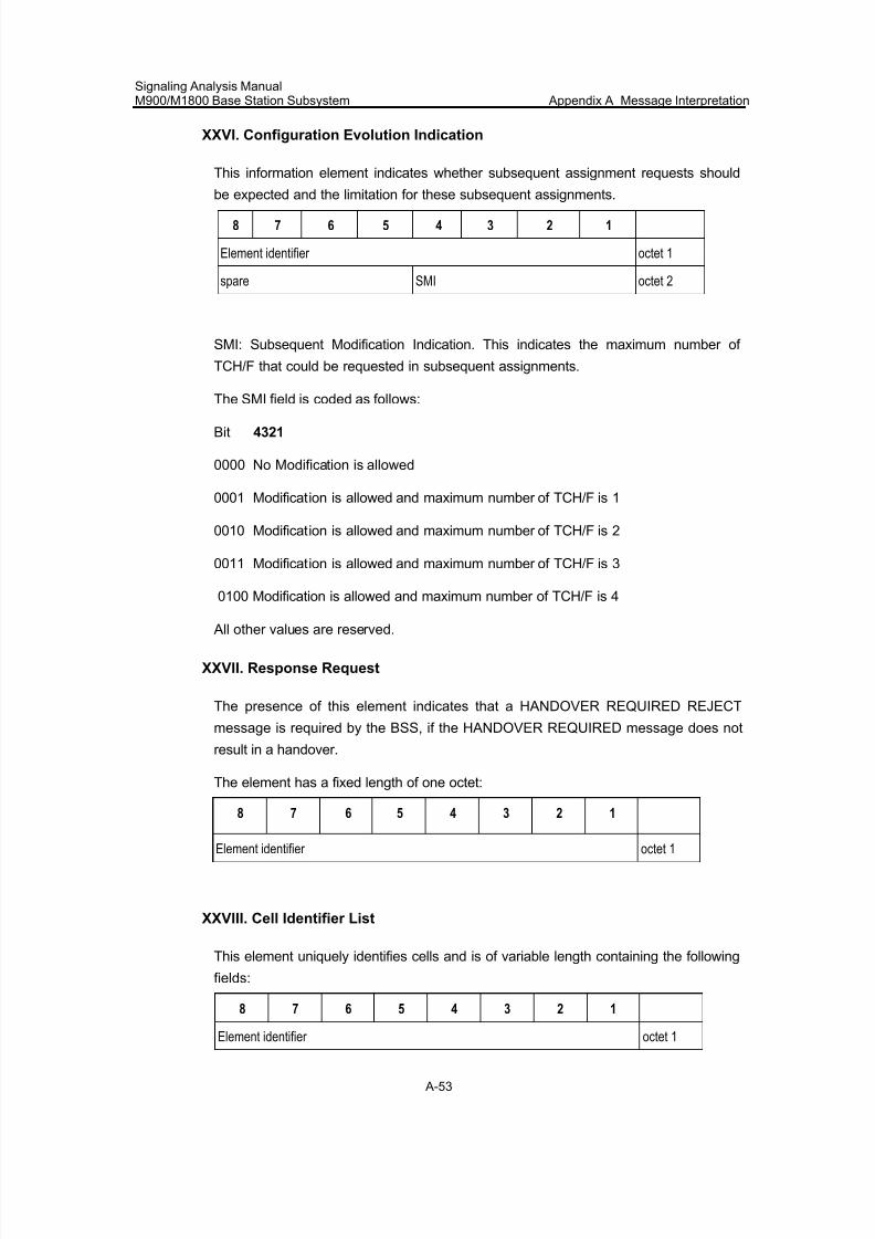
7/30/2019 Signaling Analysis Manual
http://slidepdf.com/reader/full/signaling-analysis-manual 216/290
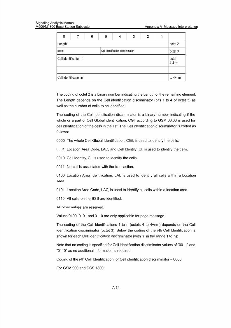
7/30/2019 Signaling Analysis Manual
http://slidepdf.com/reader/full/signaling-analysis-manual 217/290
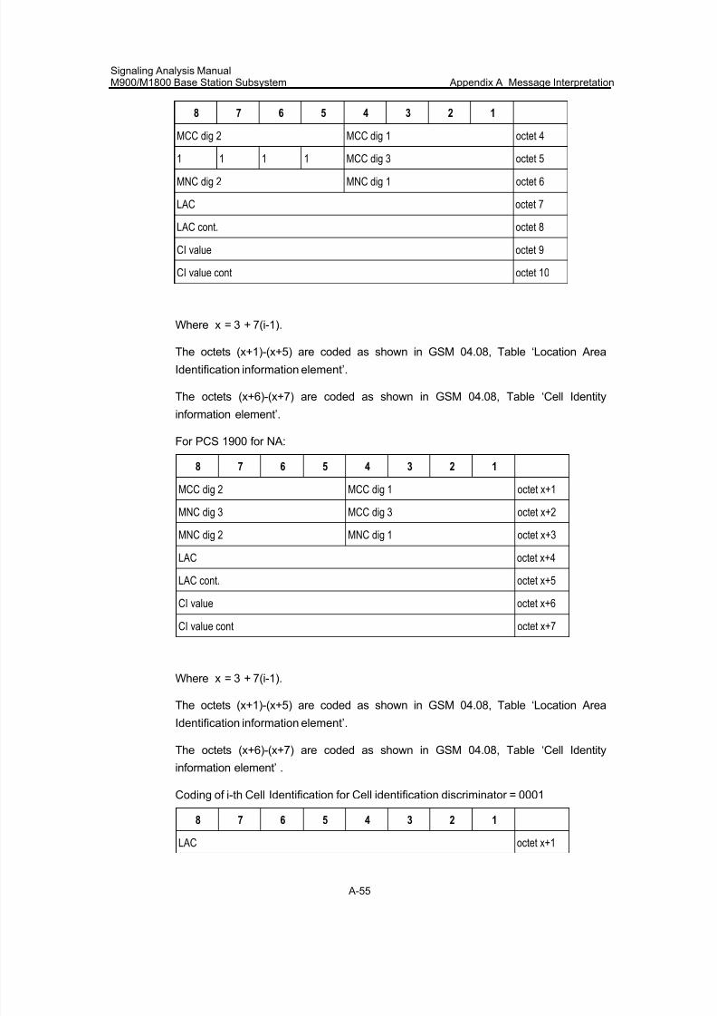
7/30/2019 Signaling Analysis Manual
http://slidepdf.com/reader/full/signaling-analysis-manual 218/290
Signaling Analysis ManualM900/M1800 Base Station Subsystem Appendix A Message Interpretation
A-55
8 7 6 5 4 3 2 1
MCC dig 2 MCC dig 1 octet 4
1 1 1 1 MCC dig 3 octet 5
MNC dig 2 MNC dig 1 octet 6
LAC octet 7
LAC cont. octet 8
CI value octet 9
CI value cont octet 10
Where x = 3 + 7(i-1).
The octets (x+1)-(x+5) are coded as shown in GSM 04.08, Table ‘Location Area
Identification information element’.
The octets (x+6)-(x+7) are coded as shown in GSM 04.08, Table ‘Cell Identity
information element’.
For PCS 1900 for NA:
8 7 6 5 4 3 2 1
MCC dig 2 MCC dig 1 octet x+1
MNC dig 3 MCC dig 3 octet x+2
MNC dig 2 MNC dig 1 octet x+3
LAC octet x+4
LAC cont. octet x+5
CI value octet x+6
CI value cont octet x+7
Where x = 3 + 7(i-1).
The octets (x+1)-(x+5) are coded as shown in GSM 04.08, Table ‘Location Area
Identification information element’.
The octets (x+6)-(x+7) are coded as shown in GSM 04.08, Table ‘Cell Identity
information element’ .
Coding of i-th Cell Identification for Cell identification discriminator = 0001
8 7 6 5 4 3 2 1
LAC octet x+1
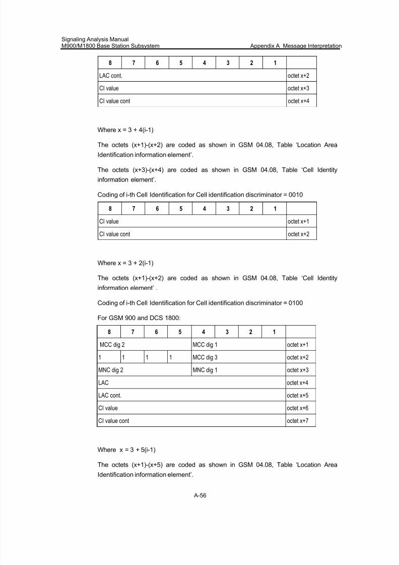
7/30/2019 Signaling Analysis Manual
http://slidepdf.com/reader/full/signaling-analysis-manual 219/290
Signaling Analysis ManualM900/M1800 Base Station Subsystem Appendix A Message Interpretation
A-56
8 7 6 5 4 3 2 1
LAC cont. octet x+2
CI value octet x+3
CI value cont octet x+4
Where x = 3 + 4(i-1)
The octets (x+1)-(x+2) are coded as shown in GSM 04.08, Table ‘Location Area
Identification information element’.
The octets (x+3)-(x+4) are coded as shown in GSM 04.08, Table ‘Cell Identity
information element’.
Coding of i-th Cell Identification for Cell identification discriminator = 0010
8 7 6 5 4 3 2 1
CI value octet x+1
CI value cont octet x+2
Where x = 3 + 2(i-1)
The octets (x+1)-(x+2) are coded as shown in GSM 04.08, Table ‘Cell Identity
information element’ .
Coding of i-th Cell Identification for Cell identification discriminator = 0100
For GSM 900 and DCS 1800:
8 7 6 5 4 3 2 1
MCC dig 2 MCC dig 1 octet x+1
1 1 1 1 MCC dig 3 octet x+2
MNC dig 2 MNC dig 1 octet x+3
LAC octet x+4
LAC cont. octet x+5
CI value octet x+6
CI value cont octet x+7
Where x = 3 + 5(i-1)
The octets (x+1)-(x+5) are coded as shown in GSM 04.08, Table ‘Location Area
Identification information element’.
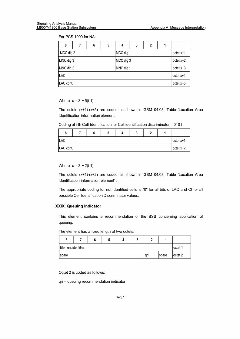
7/30/2019 Signaling Analysis Manual
http://slidepdf.com/reader/full/signaling-analysis-manual 220/290
Signaling Analysis ManualM900/M1800 Base Station Subsystem Appendix A Message Interpretation
A-57
For PCS 1900 for NA:
8 7 6 5 4 3 2 1
MCC dig 2 MCC dig 1 octet x+1
MNC dig 3 MCC dig 3 octet x+2
MNC dig 2 MNC dig 1 octet x+3
LAC octet x+4
LAC cont. octet x+5
Where x = 3 + 5(i-1)
The octets (x+1)-(x+5) are coded as shown in GSM 04.08, Table ‘Location Area
Identification information element’.
Coding of i-th Cell Identification for Cell identification discriminator = 0101
8 7 6 5 4 3 2 1
LAC octet x+1
LAC cont. octet x+2
Where x = 3 + 2(i-1)
The octets (x+1)-(x+2) are coded as shown in GSM 04.08, Table ‘Location Area
Identification information element’ .
The appropriate coding for not identified cells is "0" for all bits of LAC and CI for all
possible Cell Identification Discriminator values.
XXIX. Queuing Indicator
This element contains a recommendation of the BSS concerning application of
queuing.
The element has a fixed length of two octets.
8 7 6 5 4 3 2 1
Element identifier octet 1
spare qri spare octet 2
Octet 2 is coded as follows:
qri = queuing recommendation indicator
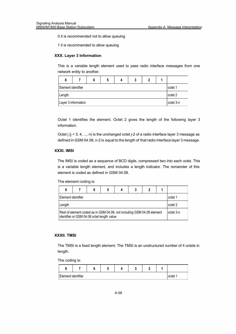
7/30/2019 Signaling Analysis Manual
http://slidepdf.com/reader/full/signaling-analysis-manual 221/290
Signaling Analysis ManualM900/M1800 Base Station Subsystem Appendix A Message Interpretation
A-58
0 it is recommended not to allow queuing
1 it is recommended to allow queuing
XXX. Layer 3 Information
This is a variable length element used to pass radio interface messages from one
network entity to another.
8 7 6 5 4 3 2 1
Element identifier octet 1
Length octet 2
Layer 3 information octet 3-n
Octet 1 identifies the element. Octet 2 gives the length of the following layer 3
information.
Octet j (j = 3, 4, ..., n) is the unchanged octet j-2 of a radio interface layer 3 message as
defined in GSM 04.08, n-2 is equal to the length of that radio interface layer 3 message.
XXXI. IMSI
The IMSI is coded as a sequence of BCD digits, compressed two into each octet. This
is a variable length element, and includes a length indicator. The remainder of thiselement is coded as defined in GSM 04.08.
The element coding is:
8 7 6 5 4 3 2 1
Element identifier octet 1
Length octet 2
Rest of element coded as in GSM 04.08, not including GSM 04.08 elementidentifier or GSM 04.08 octet length value
octet 3-n
XXXII. TMSI
The TMSI is a fixed length element. The TMSI is an unstructured number of 4 octets in
length.
The coding is:
8 7 6 5 4 3 2 1
Element identifier octet 1
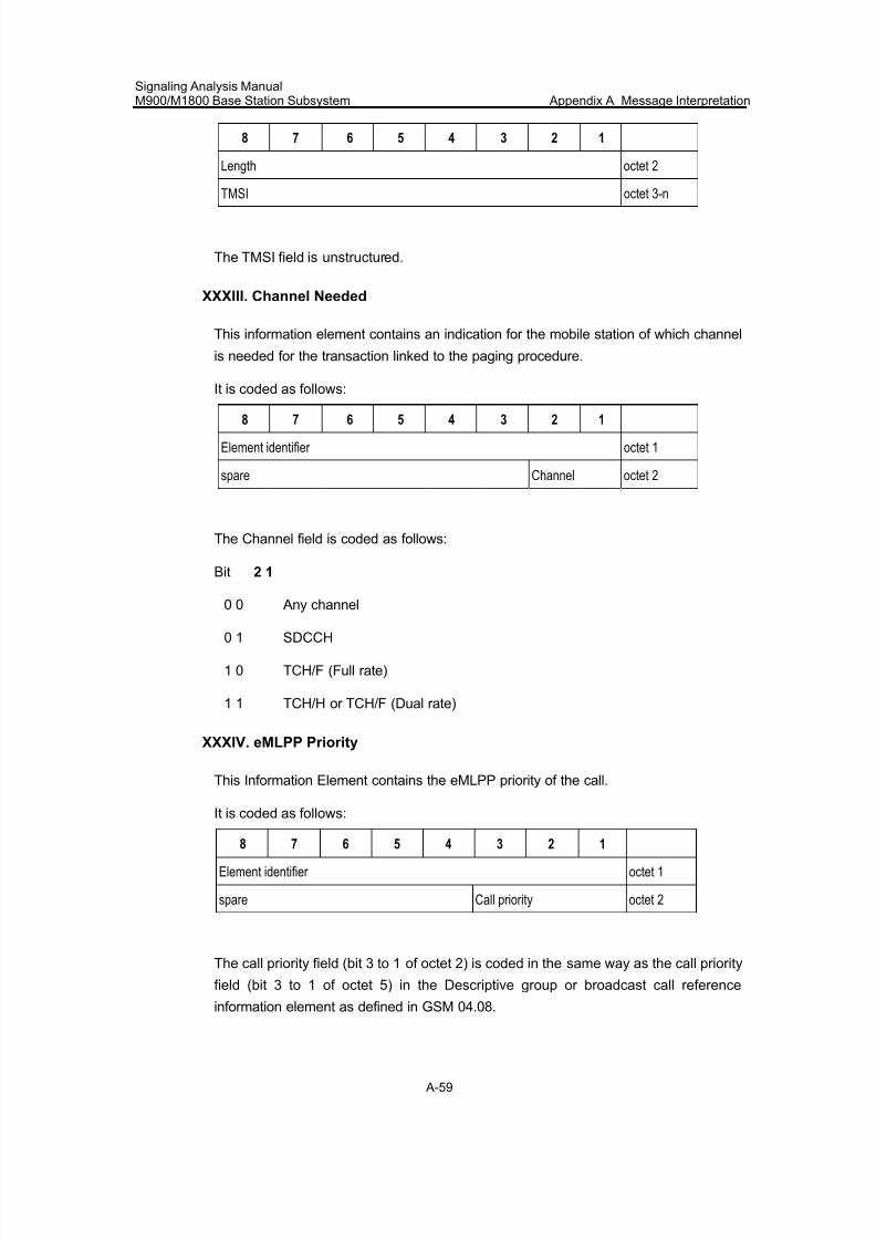
7/30/2019 Signaling Analysis Manual
http://slidepdf.com/reader/full/signaling-analysis-manual 222/290
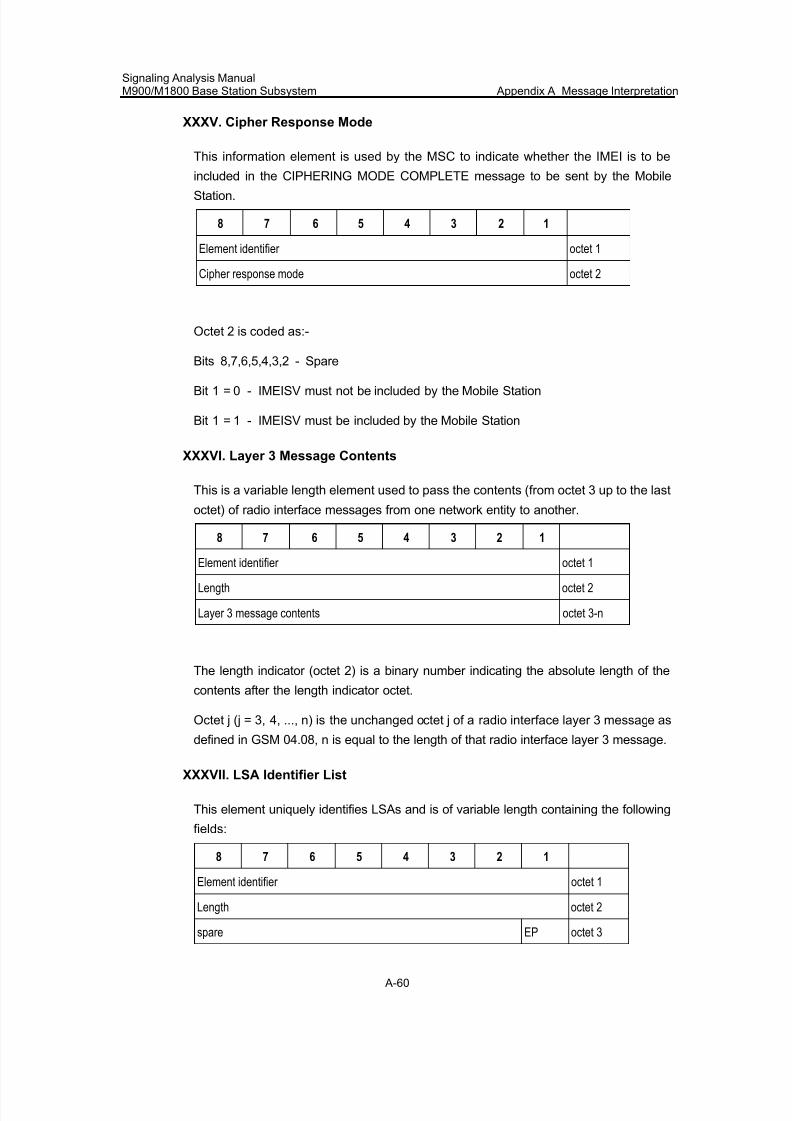
7/30/2019 Signaling Analysis Manual
http://slidepdf.com/reader/full/signaling-analysis-manual 223/290
Signaling Analysis ManualM900/M1800 Base Station Subsystem Appendix A Message Interpretation
A-60
XXXV. Cipher Response Mode
This information element is used by the MSC to indicate whether the IMEI is to be
included in the CIPHERING MODE COMPLETE message to be sent by the Mobile
Station.
8 7 6 5 4 3 2 1
Element identifier octet 1
Cipher response mode octet 2
Octet 2 is coded as:-
Bits 8,7,6,5,4,3,2 - Spare
Bit 1 = 0 - IMEISV must not be included by the Mobile Station
Bit 1 = 1 - IMEISV must be included by the Mobile Station
XXXVI. Layer 3 Message Contents
This is a variable length element used to pass the contents (from octet 3 up to the last
octet) of radio interface messages from one network entity to another.
8 7 6 5 4 3 2 1
Element identifier octet 1
Length octet 2
Layer 3 message contents octet 3-n
The length indicator (octet 2) is a binary number indicating the absolute length of the
contents after the length indicator octet.
Octet j (j = 3, 4, ..., n) is the unchanged octet j of a radio interface layer 3 message as
defined in GSM 04.08, n is equal to the length of that radio interface layer 3 message.
XXXVII. LSA Identifier List
This element uniquely identifies LSAs and is of variable length containing the following
fields:
8 7 6 5 4 3 2 1
Element identifier octet 1
Length octet 2
spare EP octet 3
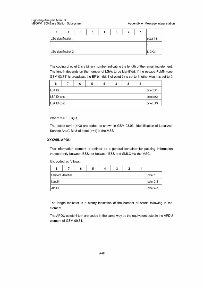
7/30/2019 Signaling Analysis Manual
http://slidepdf.com/reader/full/signaling-analysis-manual 224/290
Signaling Analysis ManualM900/M1800 Base Station Subsystem Appendix A Message Interpretation
A-61
8 7 6 5 4 3 2 1
LSA identification 1 octet 4-6
: :
LSA identification 2 to 3+3n
The coding of octet 2 is a binary number indicating the length of the remaining element.
The length depends on the number of LSAs to be identified. If the escape PLMN (see
GSM 03.73) is broadcast the EP bit (bit 1 of octet 3) is set to 1, otherwise it is set to 0.
8 7 6 5 4 3 2 1
LSA ID octet x+1
LSA ID cont. octet x+2
LSA ID cont. octet x+3
Where x = 3 + 3(i-1)
The octets (x+1)-(x+3) are coded as shown in GSM 03.03, ‘Identification of Localized
Service Area’. Bit 8 of octet (x+1) is the MSB.
XXXVIII. APDU
This information element is defined as a general container for passing information
transparently between BSSs or between BSS and SMLC via the MSC.
It is coded as follows:
8 7 6 5 4 3 2 1
Element identifier octet 1
Length octet 2-3
APDU octet 4-n
The length indicator is a binary indication of the number of octets following in the
element.
The APDU octets 4 to n are coded in the same way as the equivalent octet in the APDU
element of GSM 09.31.
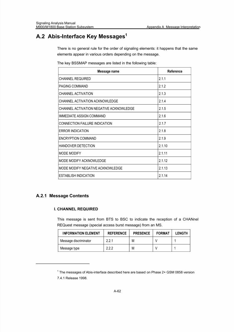
7/30/2019 Signaling Analysis Manual
http://slidepdf.com/reader/full/signaling-analysis-manual 225/290
Signaling Analysis ManualM900/M1800 Base Station Subsystem Appendix A Message Interpretation
A-62
A.2 Abis-Interface Key Messages1
There is no general rule for the order of signaling elements: it happens that the same
elements appear in various orders depending on the message.
The key BSSMAP messages are listed in the following table:
Message name Reference
CHANNEL REQUIRED 2.1.1
PAGING COMMAND 2.1.2
CHANNEL ACTIVATION 2.1.3
CHANNEL ACTIVATION ACKNOWLEDGE 2.1.4
CHANNEL ACTIVATION NEGATIVE ACKNOWLEDGE 2.1.5
IMMEDIATE ASSIGN COMMAND 2.1.6
CONNECTION FAILURE INDICATION 2.1.7
ERROR INDICATION 2.1.8
ENCRYPTION COMMAND 2.1.9
HANDOVER DETECTION 2.1.10
MODE MODIFY 2.1.11
MODE MODIFY ACKNOWLEDGE 2.1.12
MODE MODIFY NEGATIVE ACKNOWLEDGE 2.1.13
ESTABLISH INDICATION 2.1.14
A.2.1 Message Contents
I. CHANNEL REQUIRED
This message is sent from BTS to BSC to indicate the reception of a CHANnel
REQuest message (special access burst message) from an MS.
INFORMATION ELEMENT REFERENCE PRESENCE FORMAT LENGTH
Message discriminator 2.2.1 M V 1
Message type 2.2.2 M V 1
1The messages of Abis-interface described here are based on Phase 2+ GSM 0858 version
7.4.1 Release 1998.
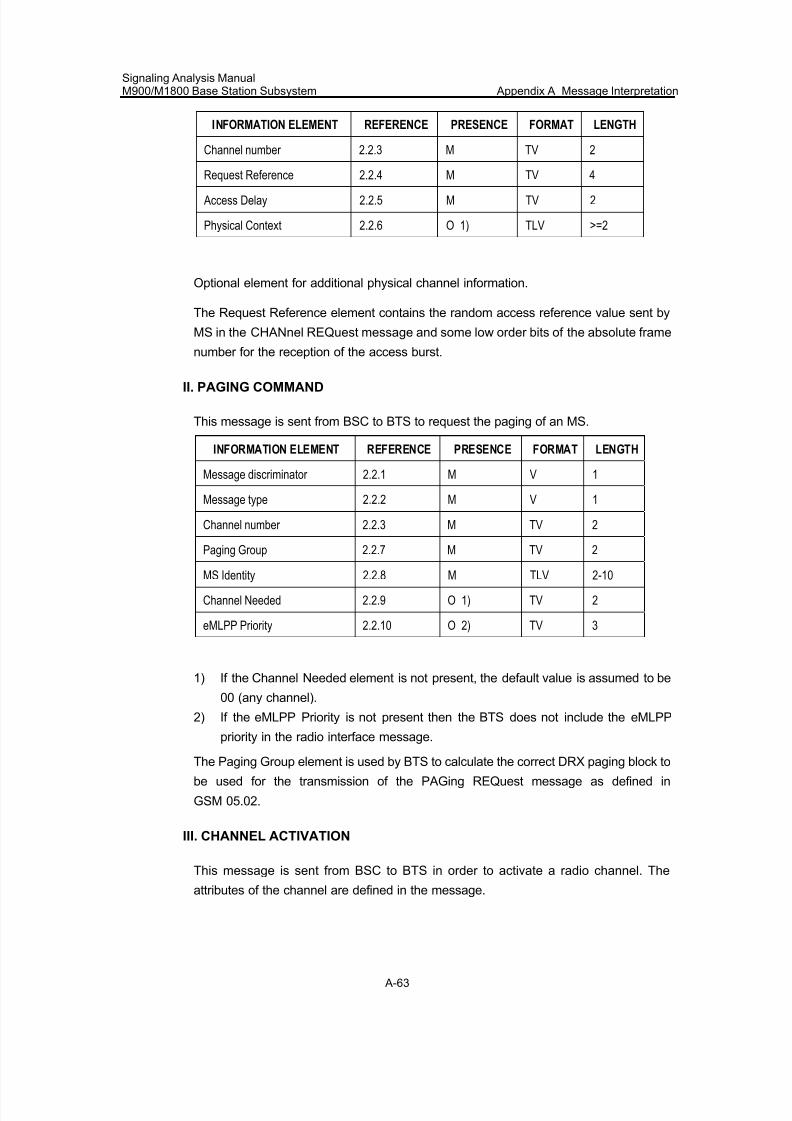
7/30/2019 Signaling Analysis Manual
http://slidepdf.com/reader/full/signaling-analysis-manual 226/290
Signaling Analysis ManualM900/M1800 Base Station Subsystem Appendix A Message Interpretation
A-63
INFORMATION ELEMENT REFERENCE PRESENCE FORMAT LENGTH
Channel number 2.2.3 M TV 2
Request Reference 2.2.4 M TV 4
Access Delay 2.2.5 M TV 2
Physical Context 2.2.6 O 1) TLV >=2
Optional element for additional physical channel information.
The Request Reference element contains the random access reference value sent by
MS in the CHANnel REQuest message and some low order bits of the absolute frame
number for the reception of the access burst.
II. PAGING COMMAND
This message is sent from BSC to BTS to request the paging of an MS.
INFORMATION ELEMENT REFERENCE PRESENCE FORMAT LENGTH
Message discriminator 2.2.1 M V 1
Message type 2.2.2 M V 1
Channel number 2.2.3 M TV 2
Paging Group 2.2.7 M TV 2
MS Identity 2.2.8 M TLV 2-10
Channel Needed 2.2.9 O 1) TV 2
eMLPP Priority 2.2.10 O 2) TV 3
1) If the Channel Needed element is not present, the default value is assumed to be
00 (any channel).
2) If the eMLPP Priority is not present then the BTS does not include the eMLPP
priority in the radio interface message.
The Paging Group element is used by BTS to calculate the correct DRX paging block to
be used for the transmission of the PAGing REQuest message as defined in
GSM 05.02.
III. CHANNEL ACTIVATION
This message is sent from BSC to BTS in order to activate a radio channel. The
attributes of the channel are defined in the message.
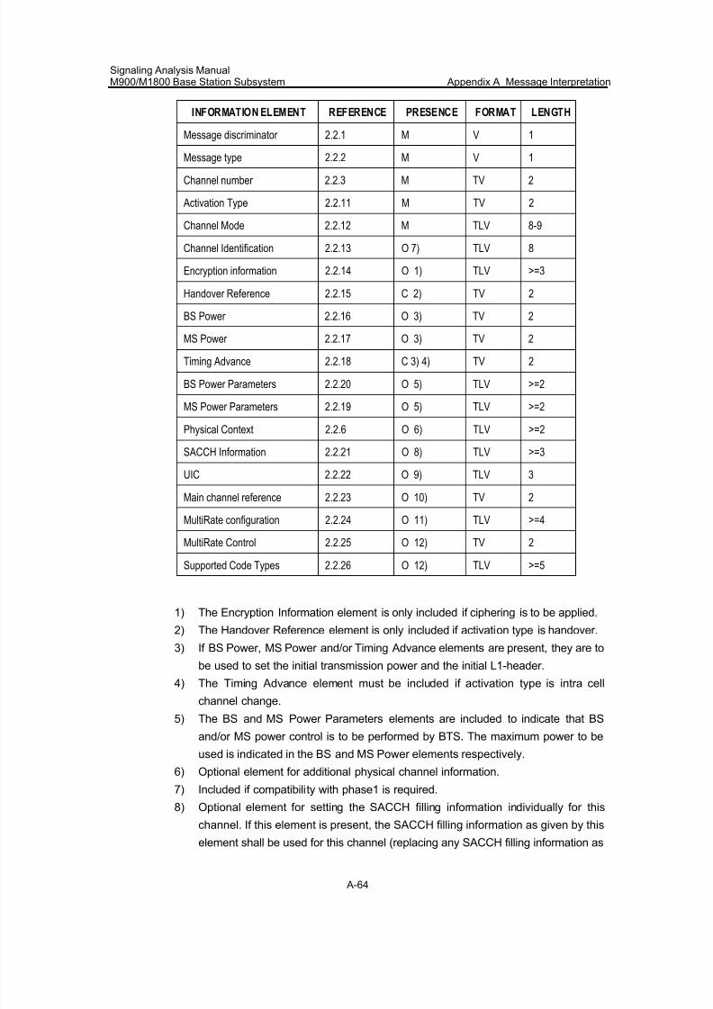
7/30/2019 Signaling Analysis Manual
http://slidepdf.com/reader/full/signaling-analysis-manual 227/290
Signaling Analysis ManualM900/M1800 Base Station Subsystem Appendix A Message Interpretation
A-64
INFORMATION ELEMENT REFERENCE PRESENCE FORMAT LENGTH
Message discriminator 2.2.1 M V 1
Message type 2.2.2 M V 1
Channel number 2.2.3 M TV 2
Activation Type 2.2.11 M TV 2
Channel Mode 2.2.12 M TLV 8-9
Channel Identification 2.2.13 O 7) TLV 8
Encryption information 2.2.14 O 1) TLV >=3
Handover Reference 2.2.15 C 2) TV 2
BS Power 2.2.16 O 3) TV 2
MS Power 2.2.17 O 3) TV 2
Timing Advance 2.2.18 C 3) 4) TV 2
BS Power Parameters 2.2.20 O 5) TLV >=2
MS Power Parameters 2.2.19 O 5) TLV >=2
Physical Context 2.2.6 O 6) TLV >=2
SACCH Information 2.2.21 O 8) TLV >=3
UIC 2.2.22 O 9) TLV 3
Main channel reference 2.2.23 O 10) TV 2
MultiRate configuration 2.2.24 O 11) TLV >=4
MultiRate Control 2.2.25 O 12) TV 2
Supported Code Types 2.2.26 O 12) TLV >=5
1) The Encryption Information element is only included if ciphering is to be applied.
2) The Handover Reference element is only included if activation type is handover.
3) If BS Power, MS Power and/or Timing Advance elements are present, they are to
be used to set the initial transmission power and the initial L1-header.
4) The Timing Advance element must be included if activation type is intra cell
channel change.
5) The BS and MS Power Parameters elements are included to indicate that BS
and/or MS power control is to be performed by BTS. The maximum power to be
used is indicated in the BS and MS Power elements respectively.
6) Optional element for additional physical channel information.
7) Included if compatibility with phase1 is required.
8) Optional element for setting the SACCH filling information individually for this
channel. If this element is present, the SACCH filling information as given by this
element shall be used for this channel (replacing any SACCH filling information as
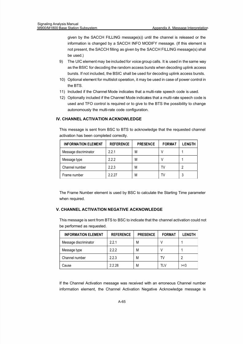
7/30/2019 Signaling Analysis Manual
http://slidepdf.com/reader/full/signaling-analysis-manual 228/290
Signaling Analysis ManualM900/M1800 Base Station Subsystem Appendix A Message Interpretation
A-65
given by the SACCH FILLING message(s)) until the channel is released or the
information is changed by a SACCH INFO MODIFY message. (If this element is
not present, the SACCH filling as given by the SACCH FILLING message(s) shall
be used.)9) The UIC element may be included for voice group calls. It is used in the same way
as the BSIC for decoding the random access bursts when decoding uplink access
bursts. If not included, the BSIC shall be used for decoding uplink access bursts.
10) Optional element for multislot operation, it may be used in case of power control in
the BTS.
11) Included if the Channel Mode indicates that a multi-rate speech code is used.
12) Optionally included if the Channel Mode indicates that a multi-rate speech code is
used and TFO control is required or to give to the BTS the possibility to change
autonomously the multi-rate code configuration.
IV. CHANNEL ACTIVATION ACKNOWLEDGE
This message is sent from BSC to BTS to acknowledge that the requested channel
activation has been completed correctly.
INFORMATION ELEMENT REFERENCE PRESENCE FORMAT LENGTH
Message discriminator 2.2.1 M V 1
Message type 2.2.2 M V 1
Channel number 2.2.3 M TV 2
Frame number 2.2.27 M TV 3
The Frame Number element is used by BSC to calculate the Starting Time parameter
when required.
V. CHANNEL ACTIVATION NEGATIVE ACKNOWLEDGE
This message is sent from BTS to BSC to indicate that the channel activation could not
be performed as requested.
INFORMATION ELEMENT REFERENCE PRESENCE FORMAT LENGTH
Message discriminator 2.2.1 M V 1
Message type 2.2.2 M V 1
Channel number 2.2.3 M TV 2
Cause 2.2.28 M TLV >=3
If the Channel Activation message was received with an erroneous Channel number
information element, the Channel Activation Negative Acknowledge message is
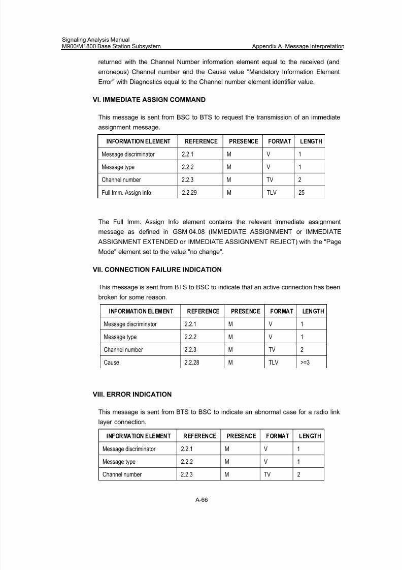
7/30/2019 Signaling Analysis Manual
http://slidepdf.com/reader/full/signaling-analysis-manual 229/290
Signaling Analysis ManualM900/M1800 Base Station Subsystem Appendix A Message Interpretation
A-66
returned with the Channel Number information element equal to the received (and
erroneous) Channel number and the Cause value "Mandatory Information Element
Error" with Diagnostics equal to the Channel number element identifier value.
VI. IMMEDIATE ASSIGN COMMAND
This message is sent from BSC to BTS to request the transmission of an immediate
assignment message.
INFORMATION ELEMENT REFERENCE PRESENCE FORMAT LENGTH
Message discriminator 2.2.1 M V 1
Message type 2.2.2 M V 1
Channel number 2.2.3 M TV 2
Full Imm. Assign Info 2.2.29 M TLV 25
The Full Imm. Assign Info element contains the relevant immediate assignment
message as defined in GSM 04.08 (IMMEDIATE ASSIGNMENT or IMMEDIATE
ASSIGNMENT EXTENDED or IMMEDIATE ASSIGNMENT REJECT) with the "Page
Mode" element set to the value "no change".
VII. CONNECTION FAILURE INDICATION
This message is sent from BTS to BSC to indicate that an active connection has been
broken for some reason.
INFORMATION ELEMENT REFERENCE PRESENCE FORMAT LENGTH
Message discriminator 2.2.1 M V 1
Message type 2.2.2 M V 1
Channel number 2.2.3 M TV 2
Cause 2.2.28 M TLV >=3
VIII. ERROR INDICATION
This message is sent from BTS to BSC to indicate an abnormal case for a radio link
layer connection.
INFORMATION ELEMENT REFERENCE PRESENCE FORMAT LENGTH
Message discriminator 2.2.1 M V 1
Message type 2.2.2 M V 1
Channel number 2.2.3 M TV 2
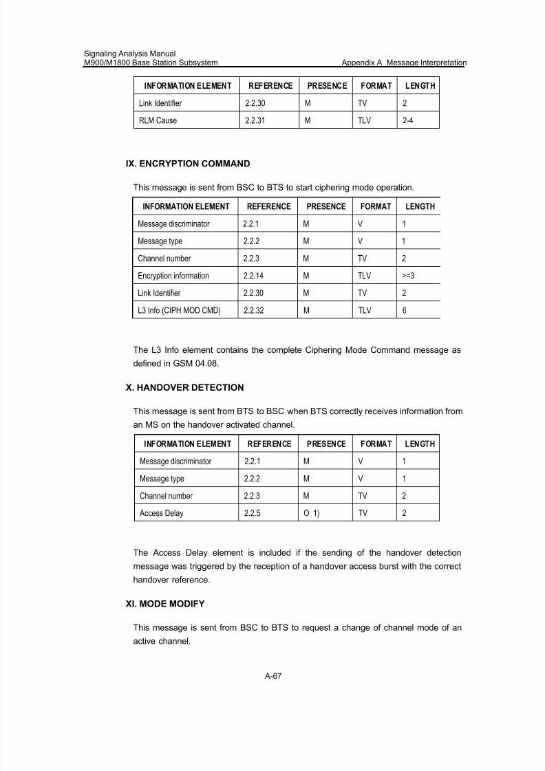
7/30/2019 Signaling Analysis Manual
http://slidepdf.com/reader/full/signaling-analysis-manual 230/290
Signaling Analysis ManualM900/M1800 Base Station Subsystem Appendix A Message Interpretation
A-67
INFORMATION ELEMENT REFERENCE PRESENCE FORMAT LENGTH
Link Identifier 2.2.30 M TV 2
RLM Cause 2.2.31 M TLV 2-4
IX. ENCRYPTION COMMAND
This message is sent from BSC to BTS to start ciphering mode operation.
INFORMATION ELEMENT REFERENCE PRESENCE FORMAT LENGTH
Message discriminator 2.2.1 M V 1
Message type 2.2.2 M V 1
Channel number 2.2.3 M TV 2
Encryption information 2.2.14 M TLV >=3
Link Identifier 2.2.30 M TV 2
L3 Info (CIPH MOD CMD) 2.2.32 M TLV 6
The L3 Info element contains the complete Ciphering Mode Command message as
defined in GSM 04.08.
X. HANDOVER DETECTION
This message is sent from BTS to BSC when BTS correctly receives information from
an MS on the handover activated channel.
INFORMATION ELEMENT REFERENCE PRESENCE FORMAT LENGTH
Message discriminator 2.2.1 M V 1
Message type 2.2.2 M V 1
Channel number 2.2.3 M TV 2
Access Delay 2.2.5 O 1) TV 2
The Access Delay element is included if the sending of the handover detection
message was triggered by the reception of a handover access burst with the correct
handover reference.
XI. MODE MODIFY
This message is sent from BSC to BTS to request a change of channel mode of an
active channel.
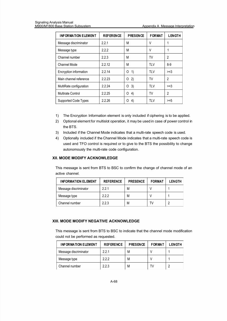
7/30/2019 Signaling Analysis Manual
http://slidepdf.com/reader/full/signaling-analysis-manual 231/290
Signaling Analysis ManualM900/M1800 Base Station Subsystem Appendix A Message Interpretation
A-68
INFORMATION ELEMENT REFERENCE PRESENCE FORMAT LENGTH
Message discriminator 2.2.1 M V 1
Message type 2.2.2 M V 1
Channel number 2.2.3 M TV 2
Channel Mode 2.2.12 M TLV 8-9
Encryption information 2.2.14 O 1) TLV >=3
Main channel reference 2.2.23 O 2) TV 2
MultiRate configuration 2.2.24 O 3) TLV >=3
Multirate Control 2.2.25 O 4) TV 2
Supported Code Types 2.2.26 O 4) TLV >=5
1) The Encryption Information element is only included if ciphering is to be applied.
2) Optional element for multislot operation, it may be used in case of power control in
the BTS.
3) Included if the Channel Mode indicates that a multi-rate speech code is used.
4) Optionally included if the Channel Mode indicates that a multi-rate speech code is
used and TFO control is required or to give to the BTS the possibility to change
autonomously the multi-rate code configuration.
XII. MODE MODIFY ACKNOWLEDGE
This message is sent from BTS to BSC to confirm the change of channel mode of an
active channel.
INFORMATION ELEMENT REFERENCE PRESENCE FORMAT LENGTH
Message discriminator 2.2.1 M V 1
Message type 2.2.2 M V 1
Channel number 2.2.3 M TV 2
XIII. MODE MODIFY NEGATIVE ACKNOWLEDGE
This message is sent from BTS to BSC to indicate that the channel mode modification
could not be performed as requested.
INFORMATION ELEMENT REFERENCE PRESENCE FORMAT LENGTH
Message discriminator 2.2.1 M V 1
Message type 2.2.2 M V 1
Channel number 2.2.3 M TV 2
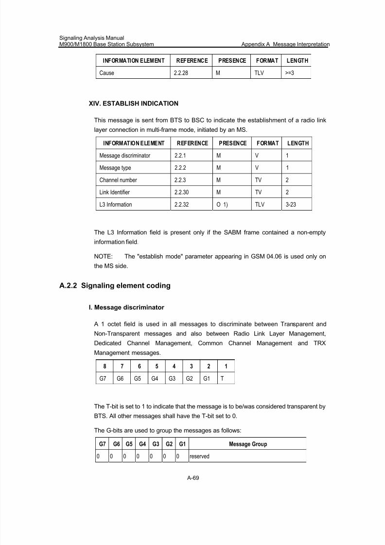
7/30/2019 Signaling Analysis Manual
http://slidepdf.com/reader/full/signaling-analysis-manual 232/290
Signaling Analysis ManualM900/M1800 Base Station Subsystem Appendix A Message Interpretation
A-69
INFORMATION ELEMENT REFERENCE PRESENCE FORMAT LENGTH
Cause 2.2.28 M TLV >=3
XIV. ESTABLISH INDICATION
This message is sent from BTS to BSC to indicate the establishment of a radio link
layer connection in multi-frame mode, initiated by an MS.
INFORMATION ELEMENT REFERENCE PRESENCE FORMAT LENGTH
Message discriminator 2.2.1 M V 1
Message type 2.2.2 M V 1
Channel number 2.2.3 M TV 2
Link Identifier 2.2.30 M TV 2
L3 Information 2.2.32 O 1) TLV 3-23
The L3 Information field is present only if the SABM frame contained a non-empty
information field.
NOTE: The "establish mode" parameter appearing in GSM 04.06 is used only on
the MS side.
A.2.2 Signaling element coding
I. Message discriminator
A 1 octet field is used in all messages to discriminate between Transparent and
Non-Transparent messages and also between Radio Link Layer Management,
Dedicated Channel Management, Common Channel Management and TRX
Management messages.
8 7 6 5 4 3 2 1
G7 G6 G5 G4 G3 G2 G1 T
The T-bit is set to 1 to indicate that the message is to be/was considered transparent by
BTS. All other messages shall have the T-bit set to 0.
The G-bits are used to group the messages as follows:
G7 G6 G5 G4 G3 G2 G1 Message Group
0 0 0 0 0 0 0 reserved
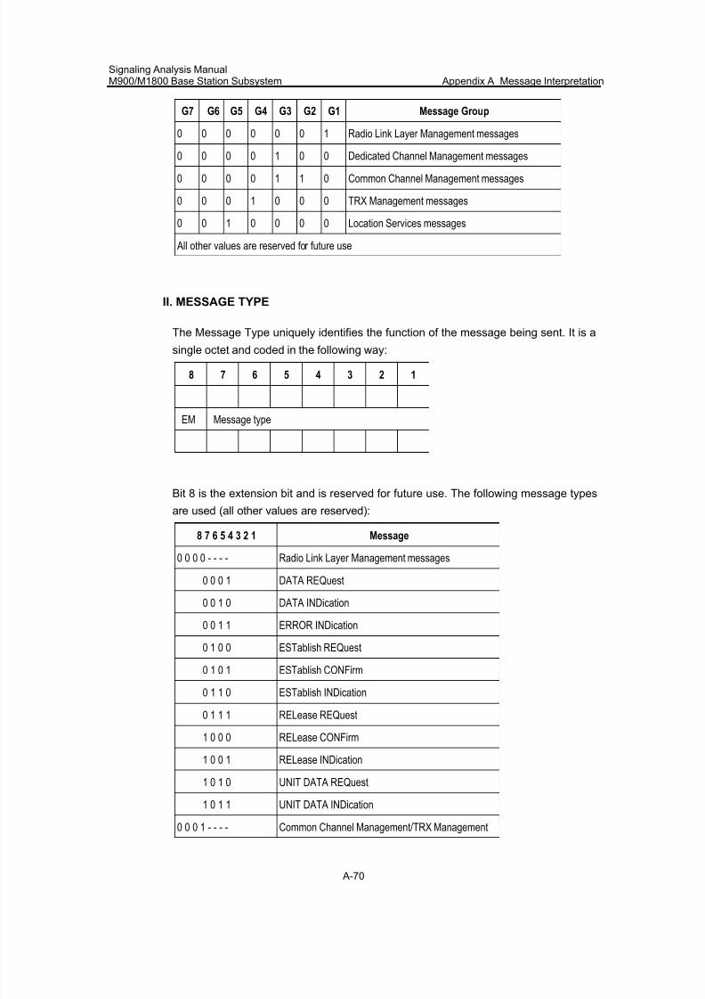
7/30/2019 Signaling Analysis Manual
http://slidepdf.com/reader/full/signaling-analysis-manual 233/290
Signaling Analysis ManualM900/M1800 Base Station Subsystem Appendix A Message Interpretation
A-70
G7 G6 G5 G4 G3 G2 G1 Message Group
0 0 0 0 0 0 1 Radio Link Layer Management messages
0 0 0 0 1 0 0 Dedicated Channel Management messages
0 0 0 0 1 1 0 Common Channel Management messages
0 0 0 1 0 0 0 TRX Management messages
0 0 1 0 0 0 0 Location Services messages
All other values are reserved for future use
II. MESSAGE TYPE
The Message Type uniquely identifies the function of the message being sent. It is asingle octet and coded in the following way:
8 7 6 5 4 3 2 1
EM Message type
Bit 8 is the extension bit and is reserved for future use. The following message types
are used (all other values are reserved):
8 7 6 5 4 3 2 1 Message
0 0 0 0 - - - - Radio Link Layer Management messages
0 0 0 1 DATA REQuest
0 0 1 0 DATA INDication
0 0 1 1 ERROR INDication
0 1 0 0 ESTablish REQuest
0 1 0 1 ESTablish CONFirm
0 1 1 0 ESTablish INDication
0 1 1 1 RELease REQuest
1 0 0 0 RELease CONFirm
1 0 0 1 RELease INDication
1 0 1 0 UNIT DATA REQuest
1 0 1 1 UNIT DATA INDication
0 0 0 1 - - - - Common Channel Management/TRX Management
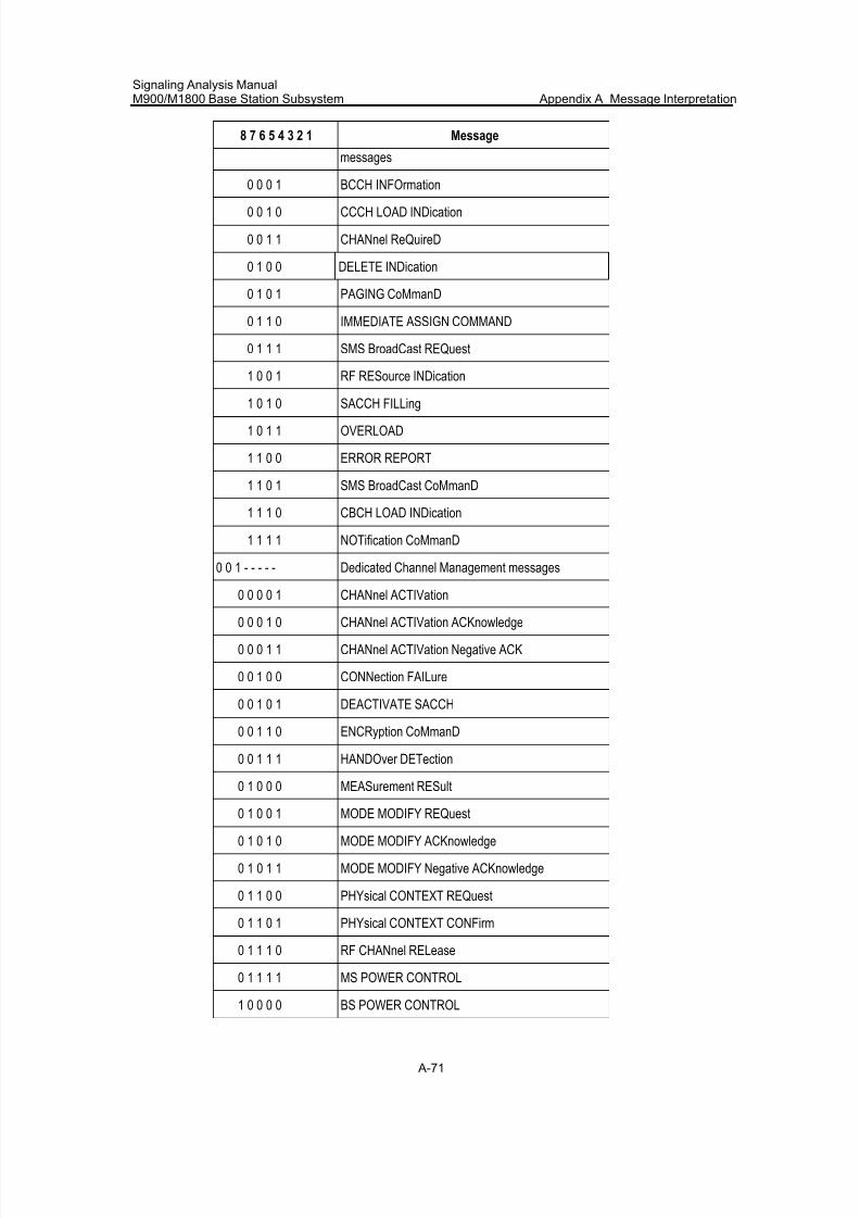
7/30/2019 Signaling Analysis Manual
http://slidepdf.com/reader/full/signaling-analysis-manual 234/290
Signaling Analysis ManualM900/M1800 Base Station Subsystem Appendix A Message Interpretation
A-71
8 7 6 5 4 3 2 1 Message
messages
0 0 0 1 BCCH INFOrmation
0 0 1 0 CCCH LOAD INDication
0 0 1 1 CHANnel ReQuireD
0 1 0 0 DELETE INDication
0 1 0 1 PAGING CoMmanD
0 1 1 0 IMMEDIATE ASSIGN COMMAND
0 1 1 1 SMS BroadCast REQuest
1 0 0 1 RF RESource INDication
1 0 1 0 SACCH FILLing
1 0 1 1 OVERLOAD
1 1 0 0 ERROR REPORT
1 1 0 1 SMS BroadCast CoMmanD
1 1 1 0 CBCH LOAD INDication
1 1 1 1 NOTification CoMmanD
0 0 1 - - - - - Dedicated Channel Management messages
0 0 0 0 1 CHANnel ACTIVation
0 0 0 1 0 CHANnel ACTIVation ACKnowledge
0 0 0 1 1 CHANnel ACTIVation Negative ACK
0 0 1 0 0 CONNection FAILure
0 0 1 0 1 DEACTIVATE SACCH
0 0 1 1 0 ENCRyption CoMmanD
0 0 1 1 1 HANDOver DETection
0 1 0 0 0 MEASurement RESult
0 1 0 0 1 MODE MODIFY REQuest
0 1 0 1 0 MODE MODIFY ACKnowledge
0 1 0 1 1 MODE MODIFY Negative ACKnowledge
0 1 1 0 0 PHYsical CONTEXT REQuest
0 1 1 0 1 PHYsical CONTEXT CONFirm
0 1 1 1 0 RF CHANnel RELease
0 1 1 1 1 MS POWER CONTROL
1 0 0 0 0 BS POWER CONTROL
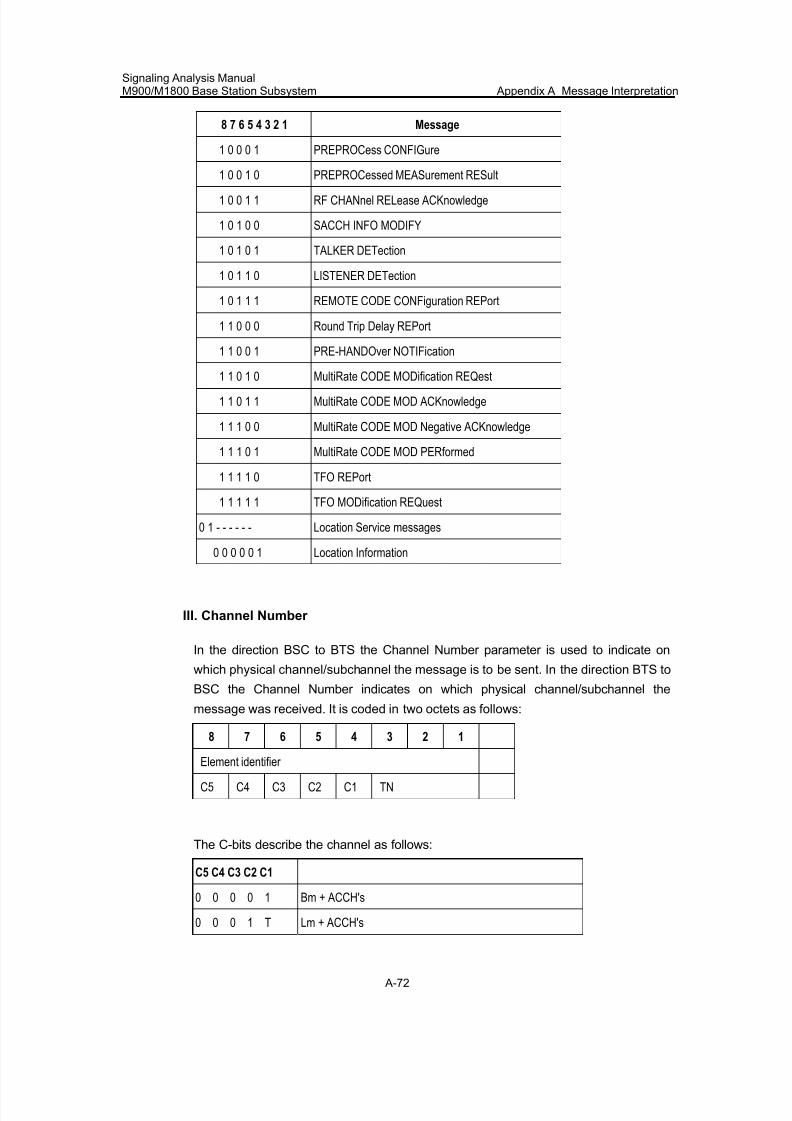
7/30/2019 Signaling Analysis Manual
http://slidepdf.com/reader/full/signaling-analysis-manual 235/290
Signaling Analysis ManualM900/M1800 Base Station Subsystem Appendix A Message Interpretation
A-72
8 7 6 5 4 3 2 1 Message
1 0 0 0 1 PREPROCess CONFIGure
1 0 0 1 0 PREPROCessed MEASurement RESult
1 0 0 1 1 RF CHANnel RELease ACKnowledge
1 0 1 0 0 SACCH INFO MODIFY
1 0 1 0 1 TALKER DETection
1 0 1 1 0 LISTENER DETection
1 0 1 1 1 REMOTE CODE CONFiguration REPort
1 1 0 0 0 Round Trip Delay REPort
1 1 0 0 1 PRE-HANDOver NOTIFication
1 1 0 1 0 MultiRate CODE MODification REQest
1 1 0 1 1 MultiRate CODE MOD ACKnowledge
1 1 1 0 0 MultiRate CODE MOD Negative ACKnowledge
1 1 1 0 1 MultiRate CODE MOD PERformed
1 1 1 1 0 TFO REPort
1 1 1 1 1 TFO MODification REQuest
0 1 - - - - - - Location Service messages
0 0 0 0 0 1 Location Information
III. Channel Number
In the direction BSC to BTS the Channel Number parameter is used to indicate on
which physical channel/subchannel the message is to be sent. In the direction BTS to
BSC the Channel Number indicates on which physical channel/subchannel the
message was received. It is coded in two octets as follows:
8 7 6 5 4 3 2 1
Element identifier
C5 C4 C3 C2 C1 TN
The C-bits describe the channel as follows:
C5 C4 C3 C2 C1
0 0 0 0 1 Bm + ACCH's
0 0 0 1 T Lm + ACCH's
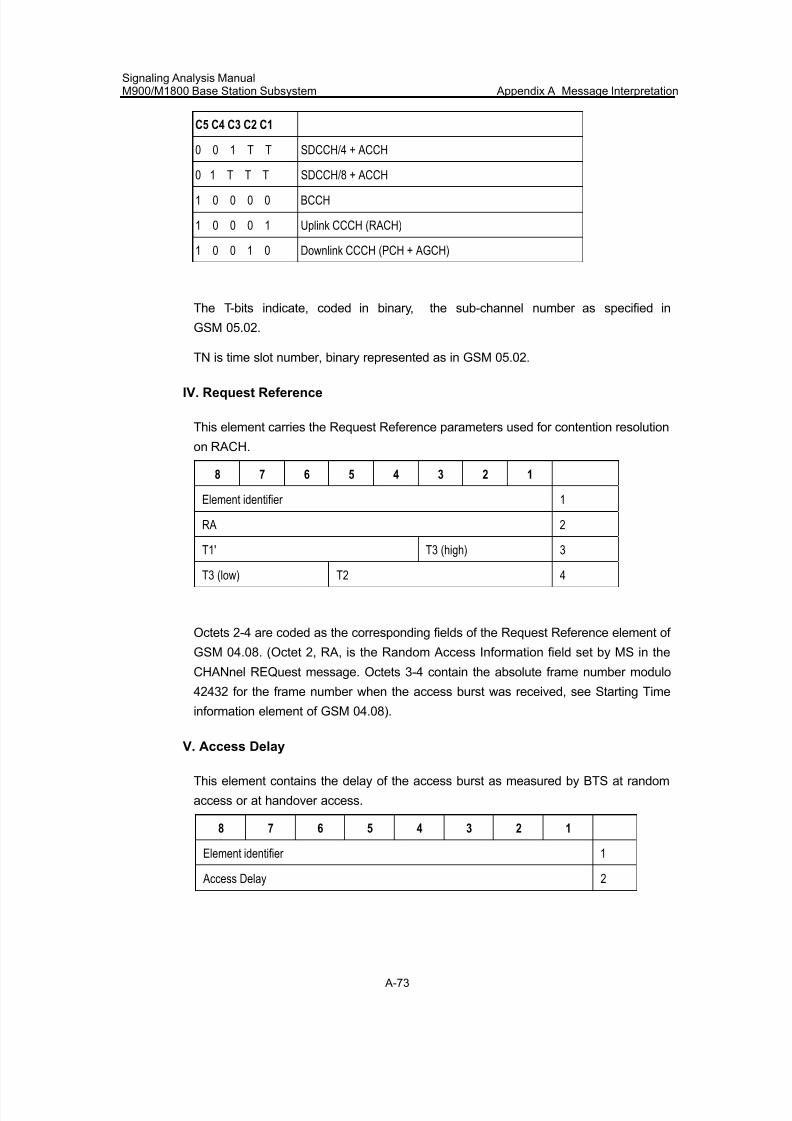
7/30/2019 Signaling Analysis Manual
http://slidepdf.com/reader/full/signaling-analysis-manual 236/290
Signaling Analysis ManualM900/M1800 Base Station Subsystem Appendix A Message Interpretation
A-73
C5 C4 C3 C2 C1
0 0 1 T T SDCCH/4 + ACCH
0 1 T T T SDCCH/8 + ACCH
1 0 0 0 0 BCCH
1 0 0 0 1 Uplink CCCH (RACH)
1 0 0 1 0 Downlink CCCH (PCH + AGCH)
The T-bits indicate, coded in binary, the sub-channel number as specified in
GSM 05.02.
TN is time slot number, binary represented as in GSM 05.02.
IV. Request Reference
This element carries the Request Reference parameters used for contention resolution
on RACH.
8 7 6 5 4 3 2 1
Element identifier 1
RA 2
T1' T3 (high) 3
T3 (low) T2 4
Octets 2-4 are coded as the corresponding fields of the Request Reference element of
GSM 04.08. (Octet 2, RA, is the Random Access Information field set by MS in the
CHANnel REQuest message. Octets 3-4 contain the absolute frame number modulo
42432 for the frame number when the access burst was received, see Starting Time
information element of GSM 04.08).
V. Access Delay
This element contains the delay of the access burst as measured by BTS at random
access or at handover access.
8 7 6 5 4 3 2 1
Element identifier 1
Access Delay 2
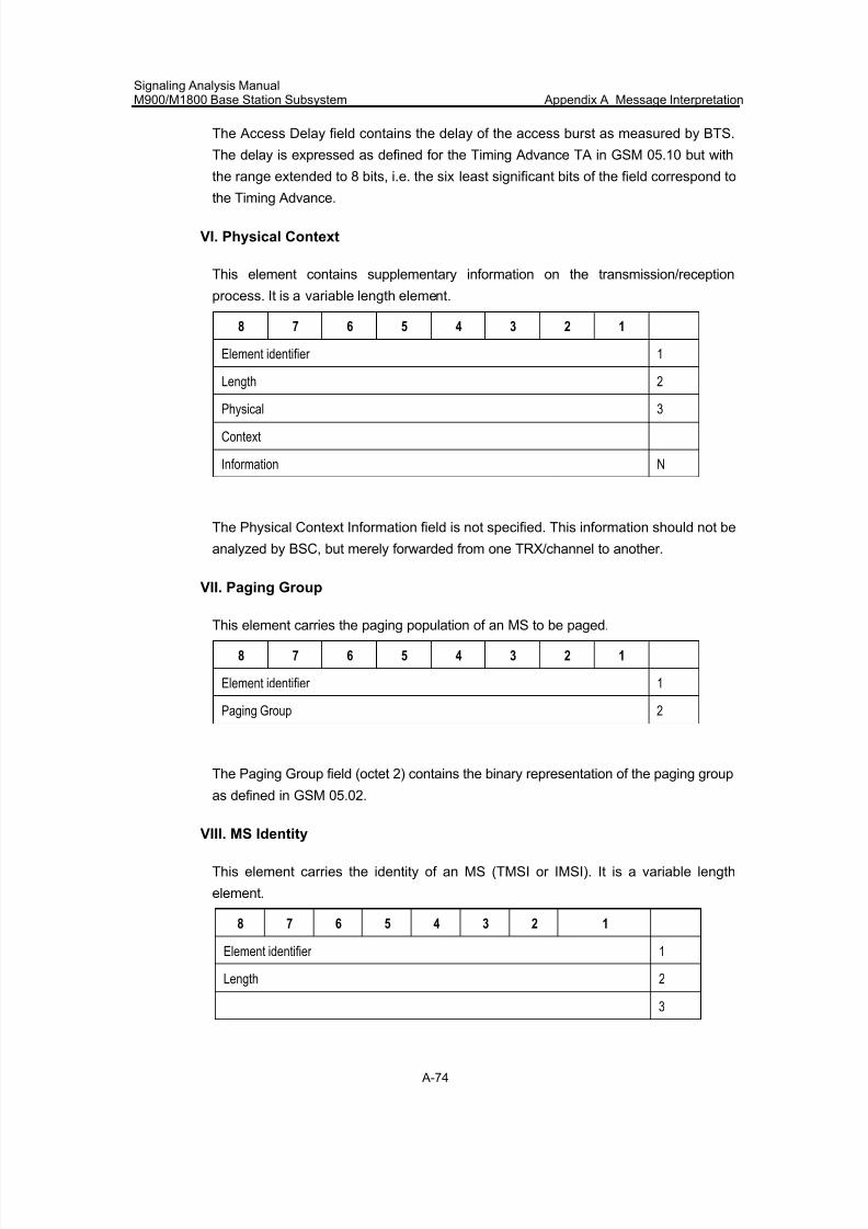
7/30/2019 Signaling Analysis Manual
http://slidepdf.com/reader/full/signaling-analysis-manual 237/290
Signaling Analysis ManualM900/M1800 Base Station Subsystem Appendix A Message Interpretation
A-74
The Access Delay field contains the delay of the access burst as measured by BTS.
The delay is expressed as defined for the Timing Advance TA in GSM 05.10 but with
the range extended to 8 bits, i.e. the six least significant bits of the field correspond to
the Timing Advance.
VI. Physical Context
This element contains supplementary information on the transmission/reception
process. It is a variable length element.
8 7 6 5 4 3 2 1
Element identifier 1
Length 2
Physical 3
Context
Information N
The Physical Context Information field is not specified. This information should not be
analyzed by BSC, but merely forwarded from one TRX/channel to another.
VII. Paging Group
This element carries the paging population of an MS to be paged.
8 7 6 5 4 3 2 1
Element identifier 1
Paging Group 2
The Paging Group field (octet 2) contains the binary representation of the paging group
as defined in GSM 05.02.
VIII. MS Identity
This element carries the identity of an MS (TMSI or IMSI). It is a variable length
element.
8 7 6 5 4 3 2 1
Element identifier 1
Length 2
3
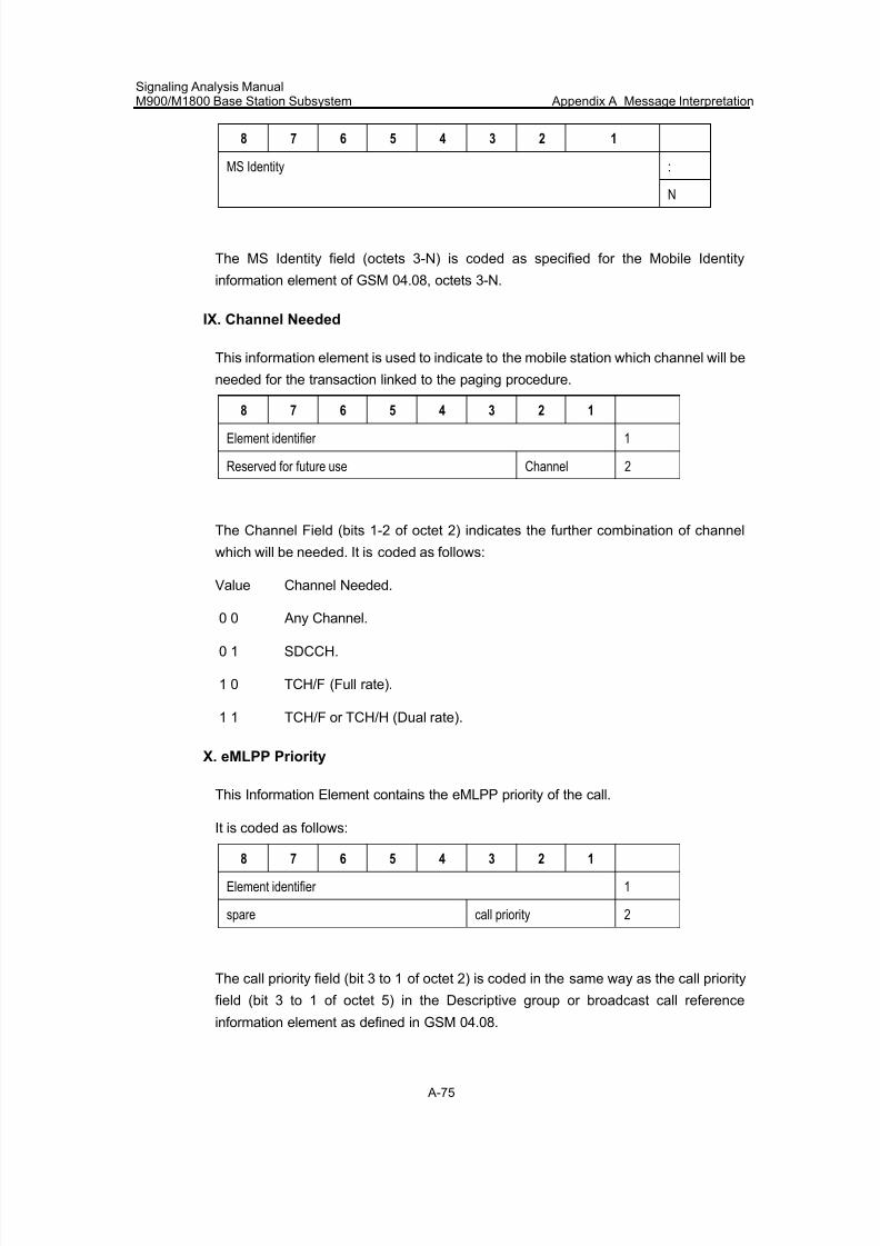
7/30/2019 Signaling Analysis Manual
http://slidepdf.com/reader/full/signaling-analysis-manual 238/290
Signaling Analysis ManualM900/M1800 Base Station Subsystem Appendix A Message Interpretation
A-75
8 7 6 5 4 3 2 1
:MS Identity
N
The MS Identity field (octets 3-N) is coded as specified for the Mobile Identity
information element of GSM 04.08, octets 3-N.
IX. Channel Needed
This information element is used to indicate to the mobile station which channel will be
needed for the transaction linked to the paging procedure.
8 7 6 5 4 3 2 1
Element identifier 1
Reserved for future use Channel 2
The Channel Field (bits 1-2 of octet 2) indicates the further combination of channel
which will be needed. It is coded as follows:
Value Channel Needed.
0 0 Any Channel.
0 1 SDCCH.
1 0 TCH/F (Full rate).
1 1 TCH/F or TCH/H (Dual rate).
X. eMLPP Priority
This Information Element contains the eMLPP priority of the call.
It is coded as follows:
8 7 6 5 4 3 2 1
Element identifier 1
spare call priority 2
The call priority field (bit 3 to 1 of octet 2) is coded in the same way as the call priority
field (bit 3 to 1 of octet 5) in the Descriptive group or broadcast call reference
information element as defined in GSM 04.08.
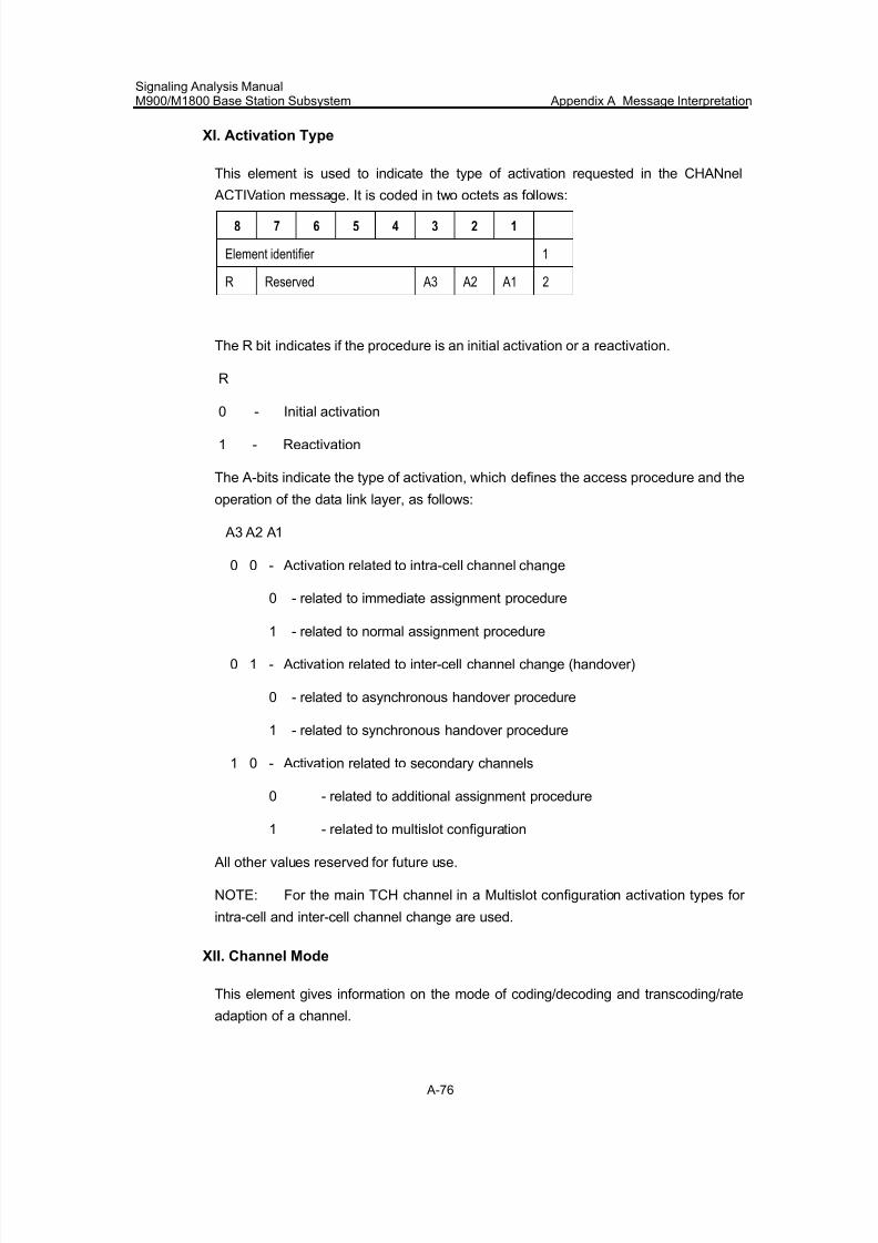
7/30/2019 Signaling Analysis Manual
http://slidepdf.com/reader/full/signaling-analysis-manual 239/290
Signaling Analysis ManualM900/M1800 Base Station Subsystem Appendix A Message Interpretation
A-76
XI. Activation Type
This element is used to indicate the type of activation requested in the CHANnel
ACTIVation message. It is coded in two octets as follows:
8 7 6 5 4 3 2 1
Element identifier 1
R Reserved A3 A2 A1 2
The R bit indicates if the procedure is an initial activation or a reactivation.
R
0 - Initial activation
1 - Reactivation
The A-bits indicate the type of activation, which defines the access procedure and the
operation of the data link layer, as follows:
A3 A2 A1
0 0 - Activation related to intra-cell channel change
0 - related to immediate assignment procedure
1 - related to normal assignment procedure
0 1 - Activation related to inter-cell channel change (handover)
0 - related to asynchronous handover procedure
1 - related to synchronous handover procedure
1 0 - Activation related to secondary channels
0 - related to additional assignment procedure
1 - related to multislot configuration
All other values reserved for future use.
NOTE: For the main TCH channel in a Multislot configuration activation types for
intra-cell and inter-cell channel change are used.
XII. Channel Mode
This element gives information on the mode of coding/decoding and transcoding/rate
adaption of a channel.
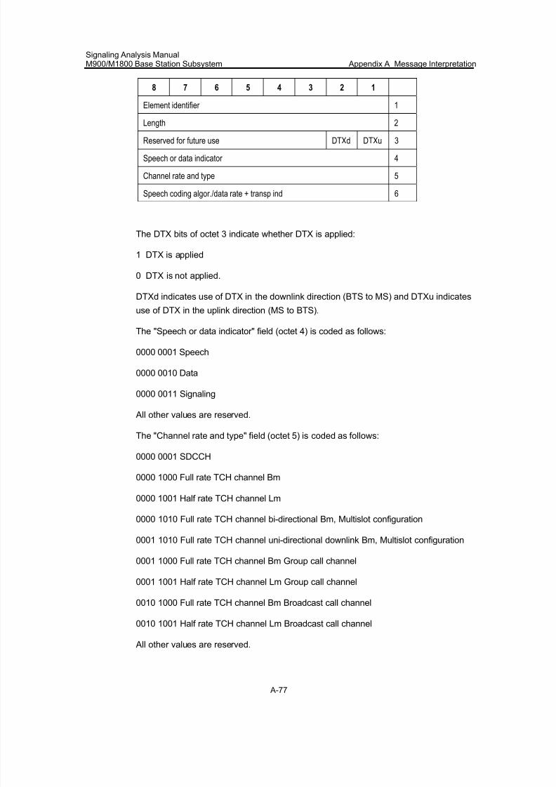
7/30/2019 Signaling Analysis Manual
http://slidepdf.com/reader/full/signaling-analysis-manual 240/290
Signaling Analysis ManualM900/M1800 Base Station Subsystem Appendix A Message Interpretation
A-77
8 7 6 5 4 3 2 1
Element identifier 1
Length 2
Reserved for future use DTXd DTXu 3
Speech or data indicator 4
Channel rate and type 5
Speech coding algor./data rate + transp ind 6
The DTX bits of octet 3 indicate whether DTX is applied:
1 DTX is applied
0 DTX is not applied.
DTXd indicates use of DTX in the downlink direction (BTS to MS) and DTXu indicates
use of DTX in the uplink direction (MS to BTS).
The "Speech or data indicator" field (octet 4) is coded as follows:
0000 0001 Speech
0000 0010 Data
0000 0011 Signaling
All other values are reserved.
The "Channel rate and type" field (octet 5) is coded as follows:
0000 0001 SDCCH
0000 1000 Full rate TCH channel Bm
0000 1001 Half rate TCH channel Lm
0000 1010 Full rate TCH channel bi-directional Bm, Multislot configuration
0001 1010 Full rate TCH channel uni-directional downlink Bm, Multislot configuration
0001 1000 Full rate TCH channel Bm Group call channel
0001 1001 Half rate TCH channel Lm Group call channel
0010 1000 Full rate TCH channel Bm Broadcast call channel
0010 1001 Half rate TCH channel Lm Broadcast call channel
All other values are reserved.
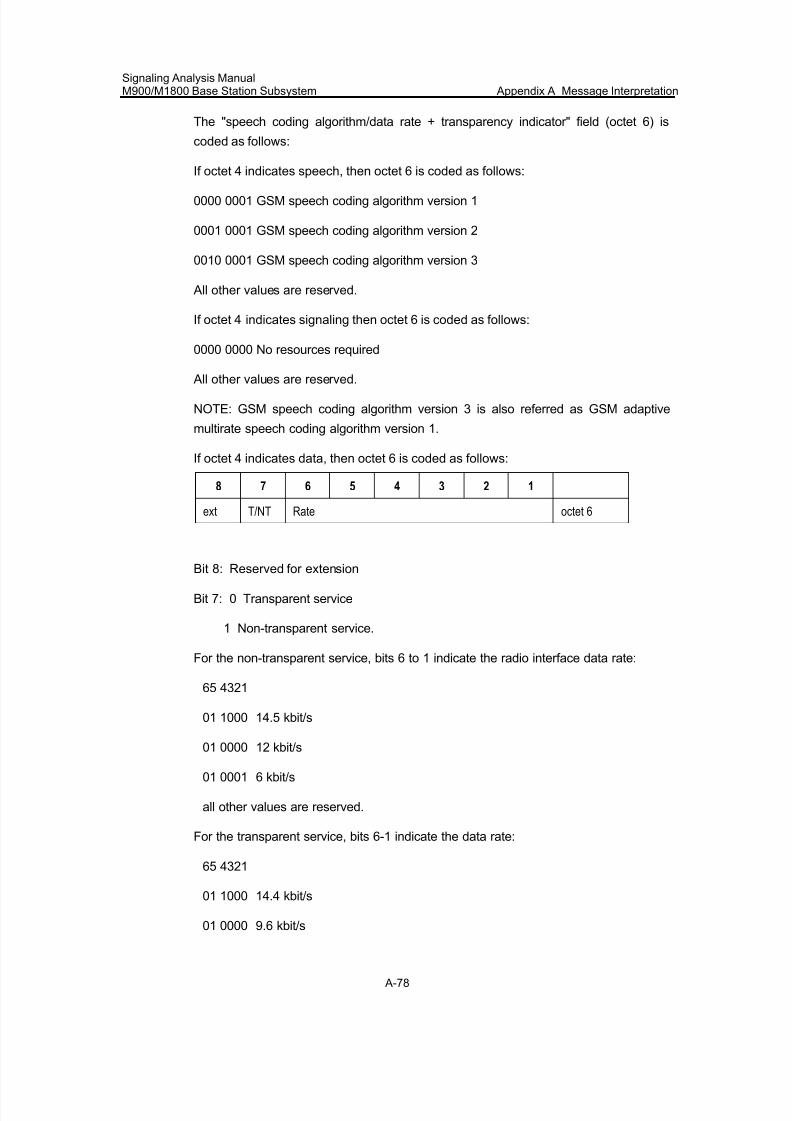
7/30/2019 Signaling Analysis Manual
http://slidepdf.com/reader/full/signaling-analysis-manual 241/290
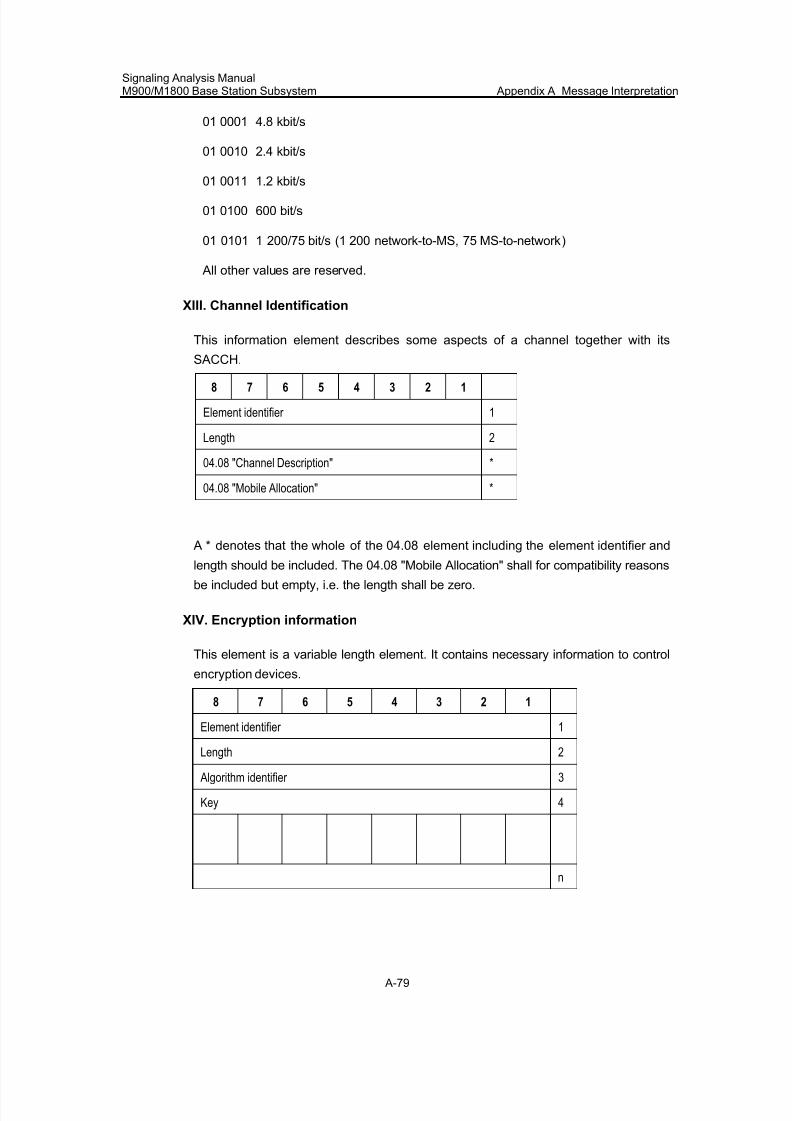
7/30/2019 Signaling Analysis Manual
http://slidepdf.com/reader/full/signaling-analysis-manual 242/290
Signaling Analysis ManualM900/M1800 Base Station Subsystem Appendix A Message Interpretation
A-79
01 0001 4.8 kbit/s
01 0010 2.4 kbit/s
01 0011 1.2 kbit/s
01 0100 600 bit/s
01 0101 1 200/75 bit/s (1 200 network-to-MS, 75 MS-to-network)
All other values are reserved.
XIII. Channel Identification
This information element describes some aspects of a channel together with its
SACCH.
8 7 6 5 4 3 2 1
Element identifier 1
Length 2
04.08 "Channel Description" *
04.08 "Mobile Allocation" *
A * denotes that the whole of the 04.08 element including the element identifier and
length should be included. The 04.08 "Mobile Allocation" shall for compatibility reasons
be included but empty, i.e. the length shall be zero.
XIV. Encryption information
This element is a variable length element. It contains necessary information to control
encryption devices.
8 7 6 5 4 3 2 1
Element identifier 1
Length 2
Algorithm identifier 3
Key 4
n
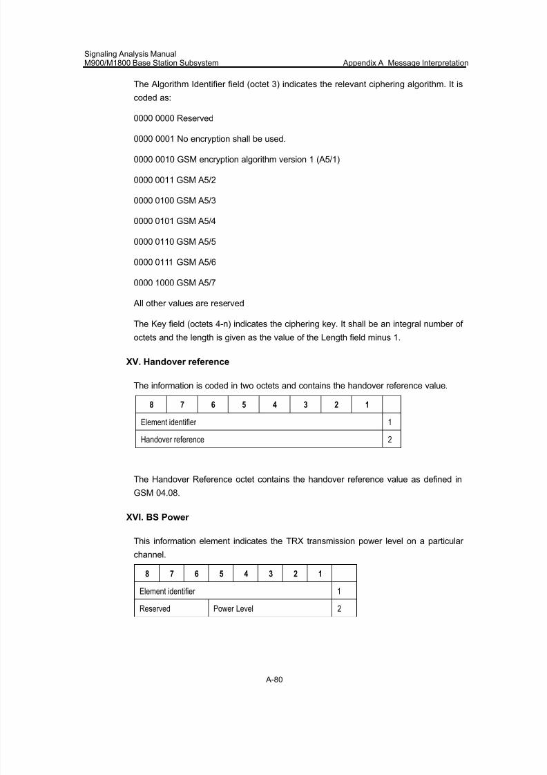
7/30/2019 Signaling Analysis Manual
http://slidepdf.com/reader/full/signaling-analysis-manual 243/290
Signaling Analysis ManualM900/M1800 Base Station Subsystem Appendix A Message Interpretation
A-80
The Algorithm Identifier field (octet 3) indicates the relevant ciphering algorithm. It is
coded as:
0000 0000 Reserved
0000 0001 No encryption shall be used.
0000 0010 GSM encryption algorithm version 1 (A5/1)
0000 0011 GSM A5/2
0000 0100 GSM A5/3
0000 0101 GSM A5/4
0000 0110 GSM A5/5
0000 0111 GSM A5/6
0000 1000 GSM A5/7
All other values are reserved
The Key field (octets 4-n) indicates the ciphering key. It shall be an integral number of
octets and the length is given as the value of the Length field minus 1.
XV. Handover reference
The information is coded in two octets and contains the handover reference value.
8 7 6 5 4 3 2 1
Element identifier 1
Handover reference 2
The Handover Reference octet contains the handover reference value as defined in
GSM 04.08.
XVI. BS Power
This information element indicates the TRX transmission power level on a particular
channel.
8 7 6 5 4 3 2 1
Element identifier 1
Reserved Power Level 2
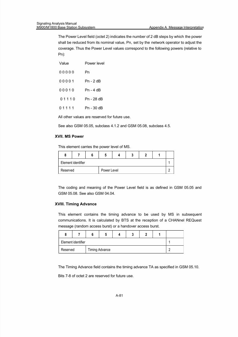
7/30/2019 Signaling Analysis Manual
http://slidepdf.com/reader/full/signaling-analysis-manual 244/290
Signaling Analysis ManualM900/M1800 Base Station Subsystem Appendix A Message Interpretation
A-81
The Power Level field (octet 2) indicates the number of 2 dB steps by which the power
shall be reduced from its nominal value, Pn, set by the network operator to adjust the
coverage. Thus the Power Level values correspond to the following powers (relative to
Pn):
Value Power level
0 0 0 0 0 Pn
0 0 0 0 1 Pn - 2 dB
0 0 0 1 0 Pn - 4 dB
0 1 1 1 0 Pn - 28 dB
0 1 1 1 1 Pn - 30 dB
All other values are reserved for future use.
See also GSM 05.05, subclass 4.1.2 and GSM 05.08, subclass 4.5.
XVII. MS Power
This element carries the power level of MS.
8 7 6 5 4 3 2 1
Element identifier 1
Reserved Power Level 2
The coding and meaning of the Power Level field is as defined in GSM 05.05 and
GSM 05.08. See also GSM 04.04.
XVIII. Timing Advance
This element contains the timing advance to be used by MS in subsequent
communications. It is calculated by BTS at the reception of a CHANnel REQuest
message (random access burst) or a handover access burst.
8 7 6 5 4 3 2 1
Element identifier 1
Reserved Timing Advance 2
The Timing Advance field contains the timing advance TA as specified in GSM 05.10.
Bits 7-8 of octet 2 are reserved for future use.
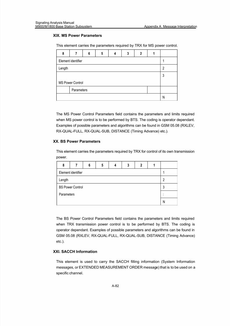
7/30/2019 Signaling Analysis Manual
http://slidepdf.com/reader/full/signaling-analysis-manual 245/290
Signaling Analysis ManualM900/M1800 Base Station Subsystem Appendix A Message Interpretation
A-82
XIX. MS Power Parameters
This element carries the parameters required by TRX for MS power control.
8 7 6 5 4 3 2 1
Element identifier 1
Length 2
MS Power Control
3
Parameters
N
The MS Power Control Parameters field contains the parameters and limits required
when MS power control is to be performed by BTS. The coding is operator dependant.
Examples of possible parameters and algorithms can be found in GSM 05.08 (RXLEV,
RX-QUAL-FULL, RX-QUAL-SUB, DISTANCE (Timing Advance) etc.).
XX. BS Power Parameters
This element carries the parameters required by TRX for control of its own transmission
power.
8 7 6 5 4 3 2 1
Element identifier 1
Length 2
3
:
BS Power Control
Parameters
N
The BS Power Control Parameters field contains the parameters and limits required
when TRX transmission power control is to be performed by BTS. The coding is
operator dependant. Examples of possible parameters and algorithms can be found in
GSM 05.08 (RXLEV, RX-QUAL-FULL, RX-QUAL-SUB, DISTANCE (Timing Advance)
etc.).
XXI. SACCH Information
This element is used to carry the SACCH filling information (System Information
messages, or EXTENDED MEASUREMENT ORDER message) that is to be used on a
specific channel.
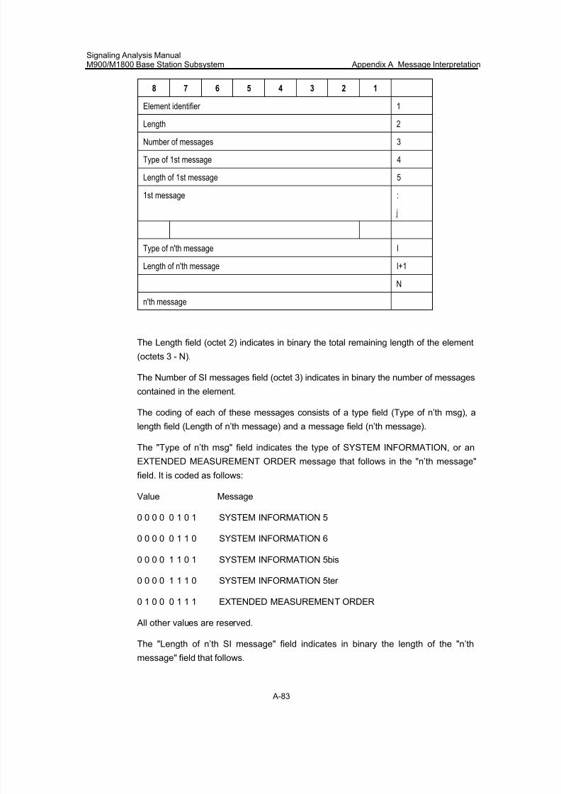
7/30/2019 Signaling Analysis Manual
http://slidepdf.com/reader/full/signaling-analysis-manual 246/290
Signaling Analysis ManualM900/M1800 Base Station Subsystem Appendix A Message Interpretation
A-83
8 7 6 5 4 3 2 1
Element identifier 1
Length 2
Number of messages 3
Type of 1st message 4
Length of 1st message 5
1st message :
j
Type of n'th message l
Length of n'th message l+1
N
n'th message
The Length field (octet 2) indicates in binary the total remaining length of the element
(octets 3 - N).
The Number of SI messages field (octet 3) indicates in binary the number of messages
contained in the element.
The coding of each of these messages consists of a type field (Type of n’th msg), a
length field (Length of n’th message) and a message field (n’th message).
The "Type of n’th msg" field indicates the type of SYSTEM INFORMATION, or an
EXTENDED MEASUREMENT ORDER message that follows in the "n’th message"
field. It is coded as follows:
Value Message
0 0 0 0 0 1 0 1 SYSTEM INFORMATION 5
0 0 0 0 0 1 1 0 SYSTEM INFORMATION 6
0 0 0 0 1 1 0 1 SYSTEM INFORMATION 5bis
0 0 0 0 1 1 1 0 SYSTEM INFORMATION 5ter
0 1 0 0 0 1 1 1 EXTENDED MEASUREMENT ORDER
All other values are reserved.
The "Length of n’th SI message" field indicates in binary the length of the "n’th
message" field that follows.
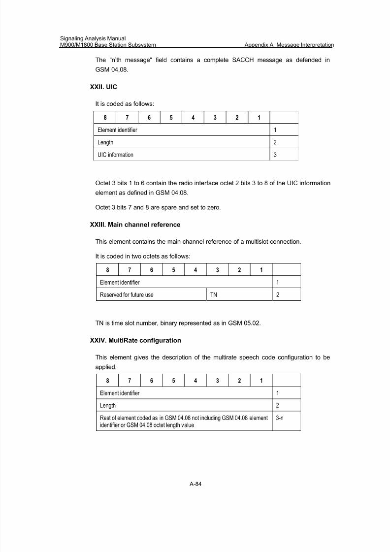
7/30/2019 Signaling Analysis Manual
http://slidepdf.com/reader/full/signaling-analysis-manual 247/290
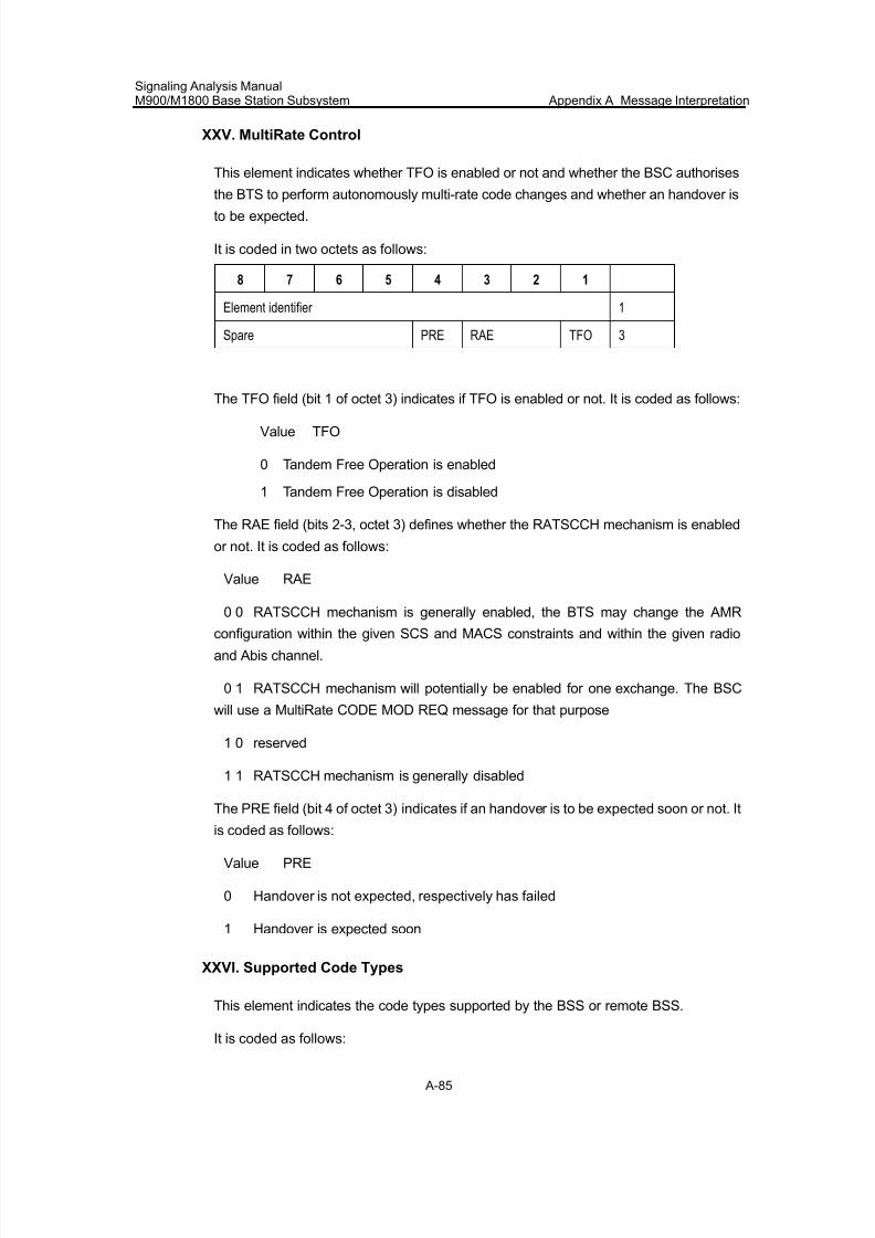
7/30/2019 Signaling Analysis Manual
http://slidepdf.com/reader/full/signaling-analysis-manual 248/290
Signaling Analysis ManualM900/M1800 Base Station Subsystem Appendix A Message Interpretation
A-85
XXV. MultiRate Control
This element indicates whether TFO is enabled or not and whether the BSC authorises
the BTS to perform autonomously multi-rate code changes and whether an handover is
to be expected.
It is coded in two octets as follows:
8 7 6 5 4 3 2 1
Element identifier 1
Spare PRE RAE TFO 3
The TFO field (bit 1 of octet 3) indicates if TFO is enabled or not. It is coded as follows:
Value TFO
0 Tandem Free Operation is enabled
1 Tandem Free Operation is disabled
The RAE field (bits 2-3, octet 3) defines whether the RATSCCH mechanism is enabled
or not. It is coded as follows:
Value RAE
0 0 RATSCCH mechanism is generally enabled, the BTS may change the AMR
configuration within the given SCS and MACS constraints and within the given radio
and Abis channel.
0 1 RATSCCH mechanism will potentially be enabled for one exchange. The BSC
will use a MultiRate CODE MOD REQ message for that purpose
1 0 reserved
1 1 RATSCCH mechanism is generally disabled
The PRE field (bit 4 of octet 3) indicates if an handover is to be expected soon or not. It
is coded as follows:
Value PRE
0 Handover is not expected, respectively has failed
1 Handover is expected soon
XXVI. Supported Code Types
This element indicates the code types supported by the BSS or remote BSS.
It is coded as follows:
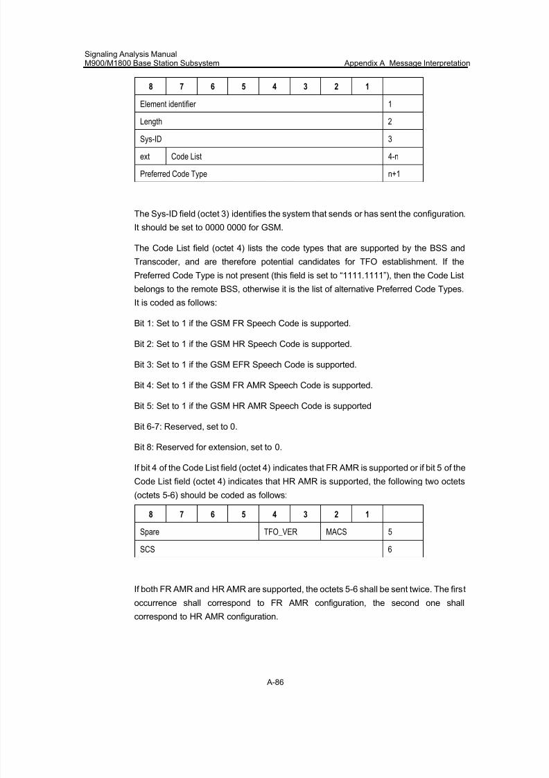
7/30/2019 Signaling Analysis Manual
http://slidepdf.com/reader/full/signaling-analysis-manual 249/290
Signaling Analysis ManualM900/M1800 Base Station Subsystem Appendix A Message Interpretation
A-86
8 7 6 5 4 3 2 1
Element identifier 1
Length 2
Sys-ID 3
ext Code List 4-n
Preferred Code Type n+1
The Sys-ID field (octet 3) identifies the system that sends or has sent the configuration.
It should be set to 0000 0000 for GSM.
The Code List field (octet 4) lists the code types that are supported by the BSS and
Transcoder, and are therefore potential candidates for TFO establishment. If the
Preferred Code Type is not present (this field is set to “1111.1111”), then the Code List
belongs to the remote BSS, otherwise it is the list of alternative Preferred Code Types.
It is coded as follows:
Bit 1: Set to 1 if the GSM FR Speech Code is supported.
Bit 2: Set to 1 if the GSM HR Speech Code is supported.
Bit 3: Set to 1 if the GSM EFR Speech Code is supported.
Bit 4: Set to 1 if the GSM FR AMR Speech Code is supported.
Bit 5: Set to 1 if the GSM HR AMR Speech Code is supported
Bit 6-7: Reserved, set to 0.
Bit 8: Reserved for extension, set to 0.
If bit 4 of the Code List field (octet 4) indicates that FR AMR is supported or if bit 5 of the
Code List field (octet 4) indicates that HR AMR is supported, the following two octets
(octets 5-6) should be coded as follows:
8 7 6 5 4 3 2 1
Spare TFO_VER MACS 5
SCS 6
If both FR AMR and HR AMR are supported, the octets 5-6 shall be sent twice. The first
occurrence shall correspond to FR AMR configuration, the second one shall
correspond to HR AMR configuration.
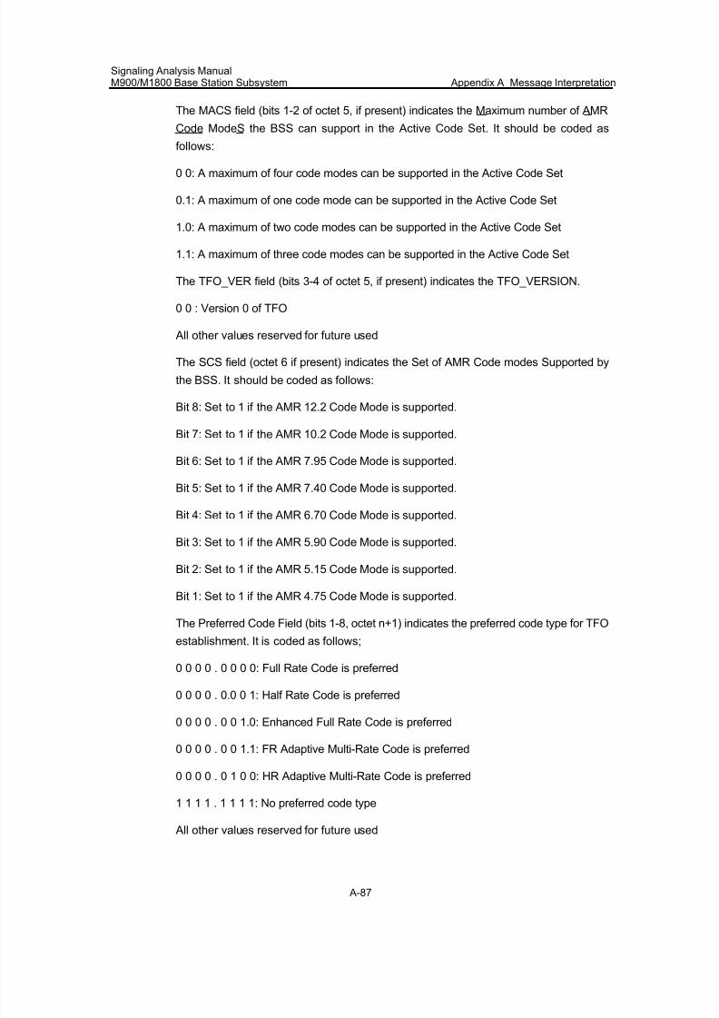
7/30/2019 Signaling Analysis Manual
http://slidepdf.com/reader/full/signaling-analysis-manual 250/290
Signaling Analysis ManualM900/M1800 Base Station Subsystem Appendix A Message Interpretation
A-87
The MACS field (bits 1-2 of octet 5, if present) indicates the Maximum number of AMR
Code ModeS the BSS can support in the Active Code Set. It should be coded as
follows:
0 0: A maximum of four code modes can be supported in the Active Code Set
0.1: A maximum of one code mode can be supported in the Active Code Set
1.0: A maximum of two code modes can be supported in the Active Code Set
1.1: A maximum of three code modes can be supported in the Active Code Set
The TFO_VER field (bits 3-4 of octet 5, if present) indicates the TFO_VERSION.
0 0 : Version 0 of TFO
All other values reserved for future used
The SCS field (octet 6 if present) indicates the Set of AMR Code modes Supported by
the BSS. It should be coded as follows:
Bit 8: Set to 1 if the AMR 12.2 Code Mode is supported.
Bit 7: Set to 1 if the AMR 10.2 Code Mode is supported.
Bit 6: Set to 1 if the AMR 7.95 Code Mode is supported.
Bit 5: Set to 1 if the AMR 7.40 Code Mode is supported.
Bit 4: Set to 1 if the AMR 6.70 Code Mode is supported.
Bit 3: Set to 1 if the AMR 5.90 Code Mode is supported.
Bit 2: Set to 1 if the AMR 5.15 Code Mode is supported.
Bit 1: Set to 1 if the AMR 4.75 Code Mode is supported.
The Preferred Code Field (bits 1-8, octet n+1) indicates the preferred code type for TFO
establishment. It is coded as follows;
0 0 0 0 . 0 0 0 0: Full Rate Code is preferred
0 0 0 0 . 0.0 0 1: Half Rate Code is preferred
0 0 0 0 . 0 0 1.0: Enhanced Full Rate Code is preferred
0 0 0 0 . 0 0 1.1: FR Adaptive Multi-Rate Code is preferred
0 0 0 0 . 0 1 0 0: HR Adaptive Multi-Rate Code is preferred
1 1 1 1 . 1 1 1 1: No preferred code type
All other values reserved for future used
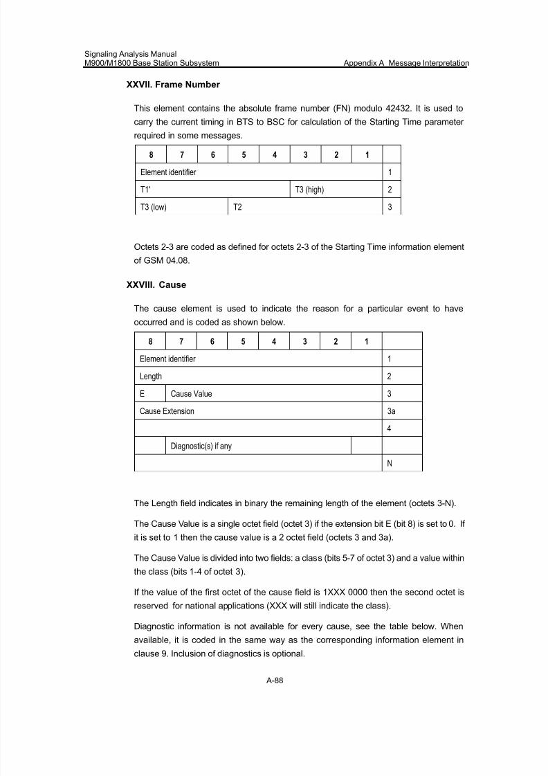
7/30/2019 Signaling Analysis Manual
http://slidepdf.com/reader/full/signaling-analysis-manual 251/290
Signaling Analysis ManualM900/M1800 Base Station Subsystem Appendix A Message Interpretation
A-88
XXVII. Frame Number
This element contains the absolute frame number (FN) modulo 42432. It is used to
carry the current timing in BTS to BSC for calculation of the Starting Time parameter
required in some messages.
8 7 6 5 4 3 2 1
Element identifier 1
T1' T3 (high) 2
T3 (low) T2 3
Octets 2-3 are coded as defined for octets 2-3 of the Starting Time information element
of GSM 04.08.
XXVIII. Cause
The cause element is used to indicate the reason for a particular event to have
occurred and is coded as shown below.
8 7 6 5 4 3 2 1
Element identifier 1
Length 2
E Cause Value 3
Cause Extension 3a
4
Diagnostic(s) if any
N
The Length field indicates in binary the remaining length of the element (octets 3-N).
The Cause Value is a single octet field (octet 3) if the extension bit E (bit 8) is set to 0. If
it is set to 1 then the cause value is a 2 octet field (octets 3 and 3a).
The Cause Value is divided into two fields: a class (bits 5-7 of octet 3) and a value within
the class (bits 1-4 of octet 3).
If the value of the first octet of the cause field is 1XXX 0000 then the second octet is
reserved for national applications (XXX will still indicate the class).
Diagnostic information is not available for every cause, see the table below. When
available, it is coded in the same way as the corresponding information element in
clause 9. Inclusion of diagnostics is optional.
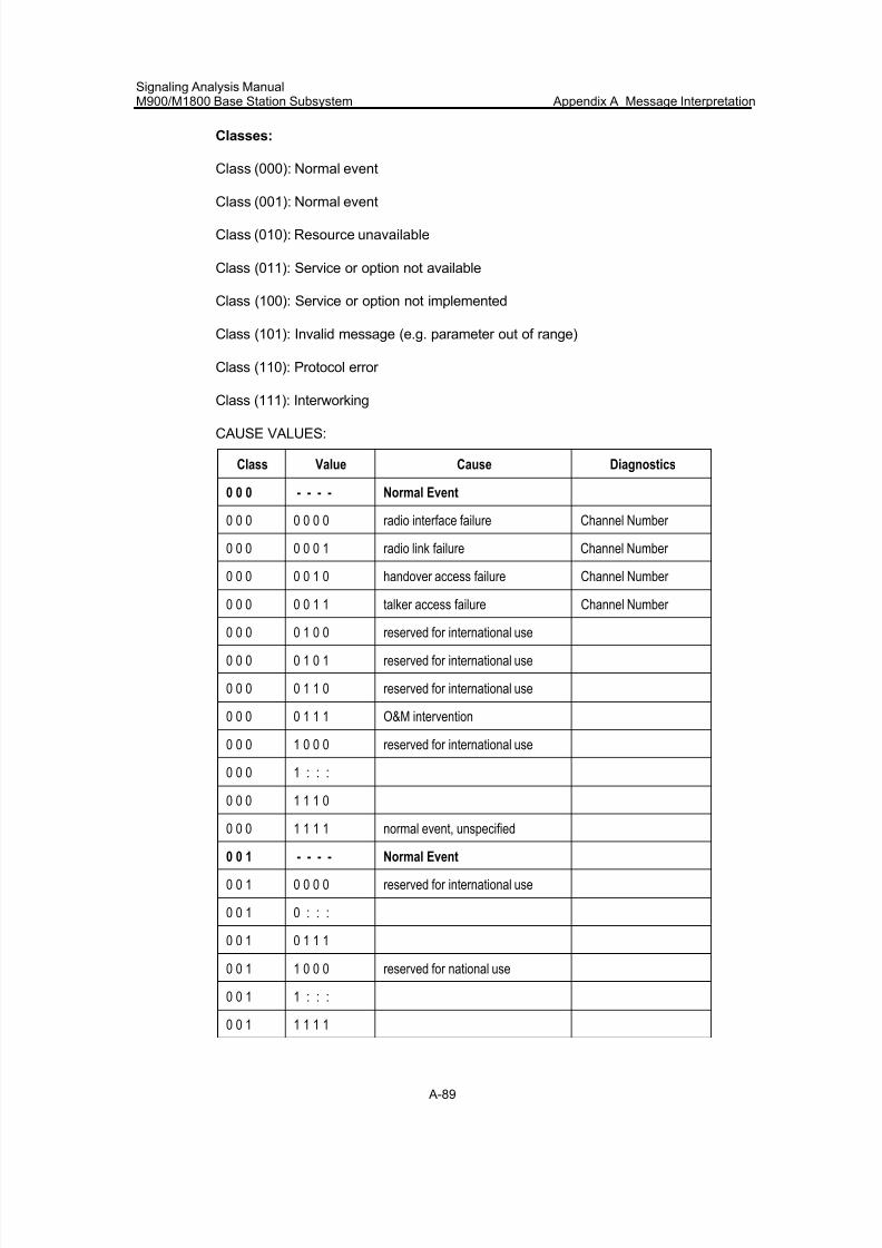
7/30/2019 Signaling Analysis Manual
http://slidepdf.com/reader/full/signaling-analysis-manual 252/290
Signaling Analysis ManualM900/M1800 Base Station Subsystem Appendix A Message Interpretation
A-89
Classes:
Class (000): Normal event
Class (001): Normal event
Class (010): Resource unavailable
Class (011): Service or option not available
Class (100): Service or option not implemented
Class (101): Invalid message (e.g. parameter out of range)
Class (110): Protocol error
Class (111): Interworking
CAUSE VALUES:
Class Value Cause Diagnostics
0 0 0 - - - - Normal Event
0 0 0 0 0 0 0 radio interface failure Channel Number
0 0 0 0 0 0 1 radio link failure Channel Number
0 0 0 0 0 1 0 handover access failure Channel Number
0 0 0 0 0 1 1 talker access failure Channel Number
0 0 0 0 1 0 0 reserved for international use
0 0 0 0 1 0 1 reserved for international use
0 0 0 0 1 1 0 reserved for international use
0 0 0 0 1 1 1 O&M intervention
0 0 0 1 0 0 0 reserved for international use
0 0 0 1 : : :
0 0 0 1 1 1 0
0 0 0 1 1 1 1 normal event, unspecified
0 0 1 - - - - Normal Event
0 0 1 0 0 0 0 reserved for international use
0 0 1 0 : : :
0 0 1 0 1 1 1
0 0 1 1 0 0 0 reserved for national use
0 0 1 1 : : :
0 0 1 1 1 1 1
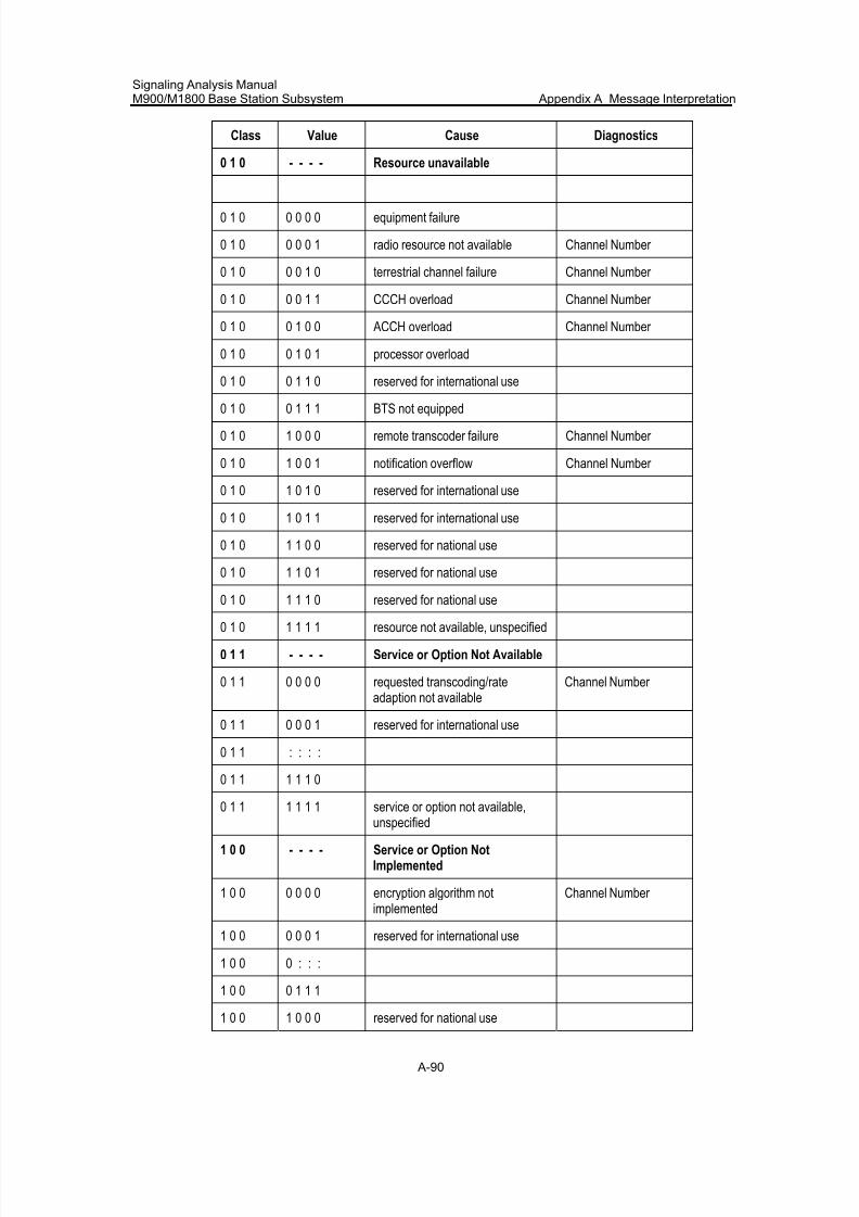
7/30/2019 Signaling Analysis Manual
http://slidepdf.com/reader/full/signaling-analysis-manual 253/290
Signaling Analysis ManualM900/M1800 Base Station Subsystem Appendix A Message Interpretation
A-90
Class Value Cause Diagnostics
0 1 0 - - - - Resource unavailable
0 1 0 0 0 0 0 equipment failure
0 1 0 0 0 0 1 radio resource not available Channel Number
0 1 0 0 0 1 0 terrestrial channel failure Channel Number
0 1 0 0 0 1 1 CCCH overload Channel Number
0 1 0 0 1 0 0 ACCH overload Channel Number
0 1 0 0 1 0 1 processor overload
0 1 0 0 1 1 0 reserved for international use
0 1 0 0 1 1 1 BTS not equipped
0 1 0 1 0 0 0 remote transcoder failure Channel Number
0 1 0 1 0 0 1 notification overflow Channel Number
0 1 0 1 0 1 0 reserved for international use
0 1 0 1 0 1 1 reserved for international use
0 1 0 1 1 0 0 reserved for national use
0 1 0 1 1 0 1 reserved for national use
0 1 0 1 1 1 0 reserved for national use
0 1 0 1 1 1 1 resource not available, unspecified
0 1 1 - - - - Service or Option Not Available
0 1 1 0 0 0 0 requested transcoding/rateadaption not available
Channel Number
0 1 1 0 0 0 1 reserved for international use
0 1 1 : : : :
0 1 1 1 1 1 0
0 1 1 1 1 1 1 service or option not available,unspecified
1 0 0 - - - - Service or Option NotImplemented
1 0 0 0 0 0 0 encryption algorithm notimplemented
Channel Number
1 0 0 0 0 0 1 reserved for international use
1 0 0 0 : : :
1 0 0 0 1 1 1
1 0 0 1 0 0 0 reserved for national use
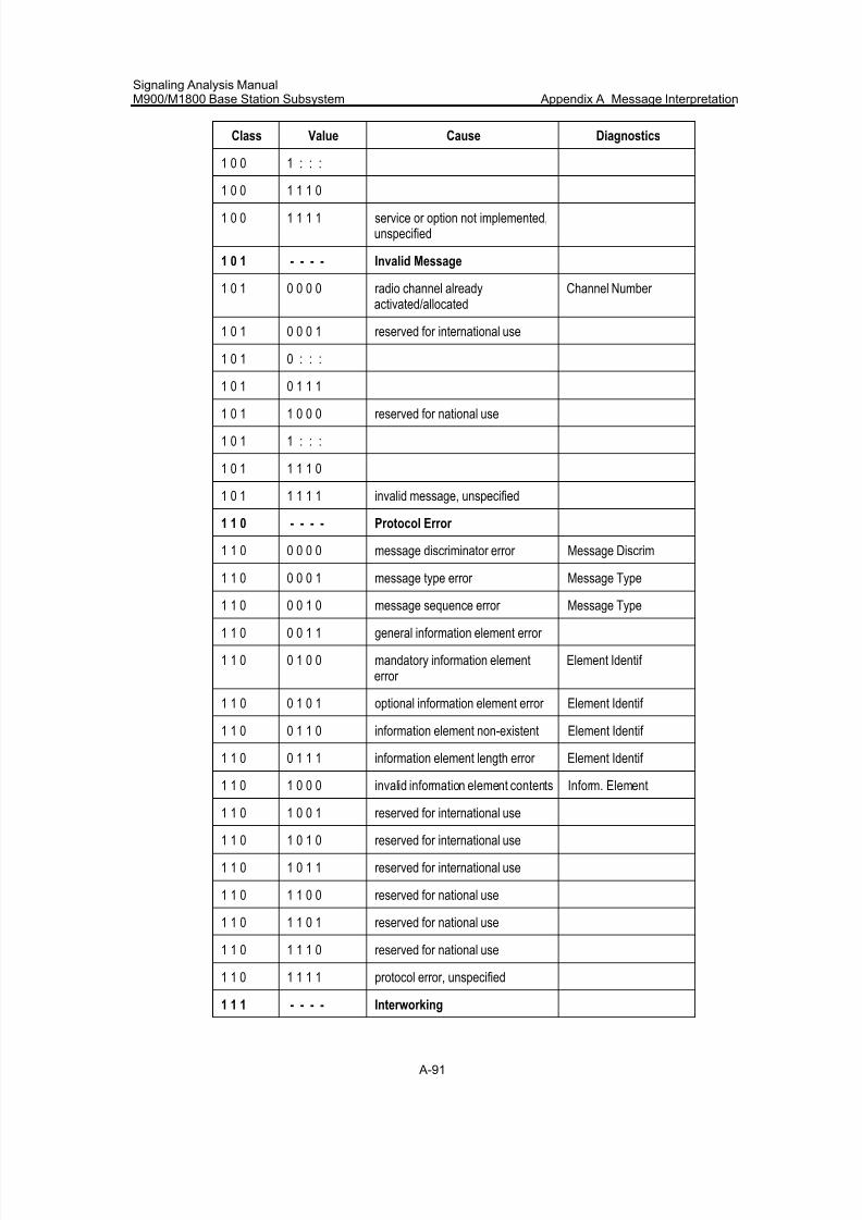
7/30/2019 Signaling Analysis Manual
http://slidepdf.com/reader/full/signaling-analysis-manual 254/290
Signaling Analysis ManualM900/M1800 Base Station Subsystem Appendix A Message Interpretation
A-91
Class Value Cause Diagnostics
1 0 0 1 : : :
1 0 0 1 1 1 0
1 0 0 1 1 1 1 service or option not implemented,unspecified
1 0 1 - - - - Invalid Message
1 0 1 0 0 0 0 radio channel alreadyactivated/allocated
Channel Number
1 0 1 0 0 0 1 reserved for international use
1 0 1 0 : : :
1 0 1 0 1 1 1
1 0 1 1 0 0 0 reserved for national use
1 0 1 1 : : :
1 0 1 1 1 1 0
1 0 1 1 1 1 1 invalid message, unspecified
1 1 0 - - - - Protocol Error
1 1 0 0 0 0 0 message discriminator error Message Discrim
1 1 0 0 0 0 1 message type error Message Type
1 1 0 0 0 1 0 message sequence error Message Type
1 1 0 0 0 1 1 general information element error
1 1 0 0 1 0 0 mandatory information elementerror
Element Identif
1 1 0 0 1 0 1 optional information element error Element Identif
1 1 0 0 1 1 0 information element non-existent Element Identif
1 1 0 0 1 1 1 information element length error Element Identif
1 1 0 1 0 0 0 invalid information element contents Inform. Element
1 1 0 1 0 0 1 reserved for international use
1 1 0 1 0 1 0 reserved for international use
1 1 0 1 0 1 1 reserved for international use
1 1 0 1 1 0 0 reserved for national use
1 1 0 1 1 0 1 reserved for national use
1 1 0 1 1 1 0 reserved for national use
1 1 0 1 1 1 1 protocol error, unspecified
1 1 1 - - - - Interworking
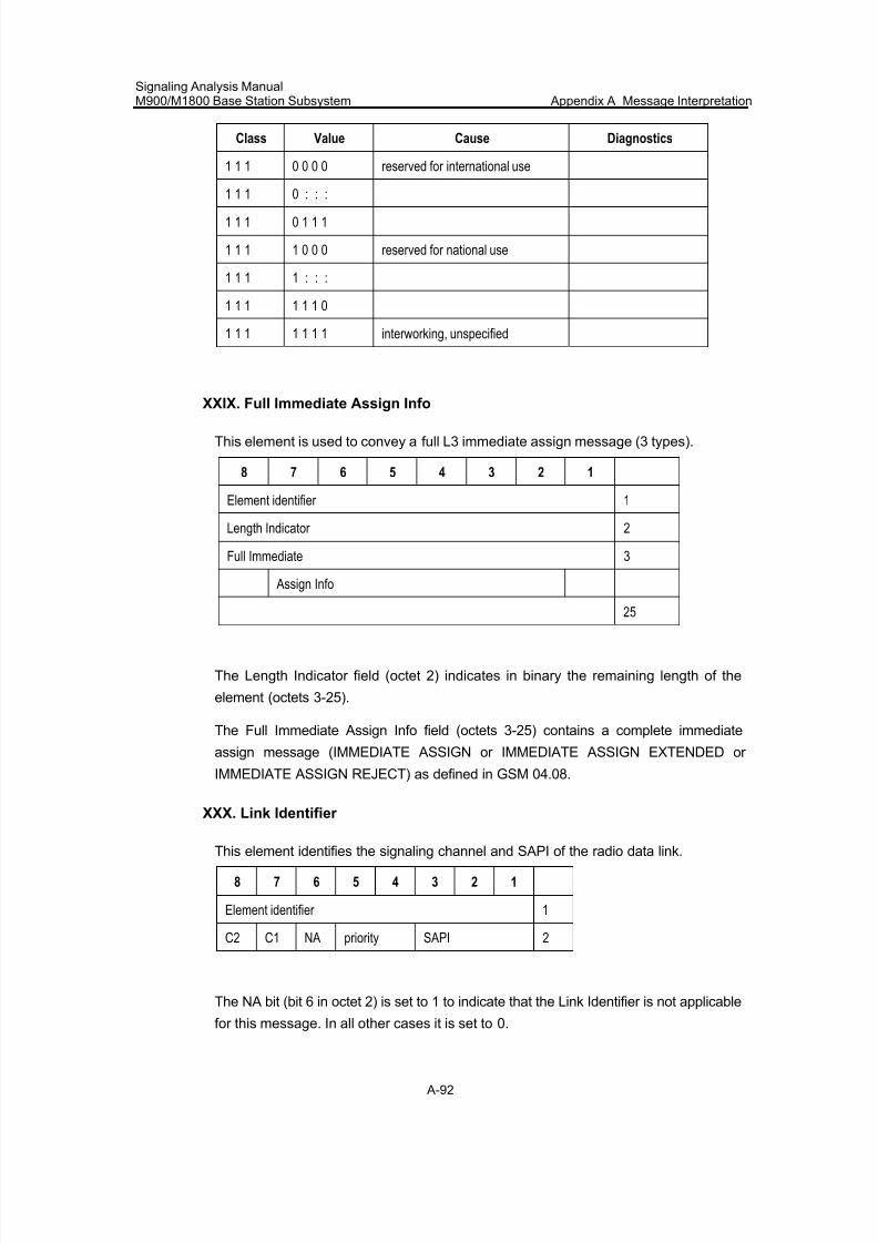
7/30/2019 Signaling Analysis Manual
http://slidepdf.com/reader/full/signaling-analysis-manual 255/290
Signaling Analysis ManualM900/M1800 Base Station Subsystem Appendix A Message Interpretation
A-92
Class Value Cause Diagnostics
1 1 1 0 0 0 0 reserved for international use
1 1 1 0 : : :
1 1 1 0 1 1 1
1 1 1 1 0 0 0 reserved for national use
1 1 1 1 : : :
1 1 1 1 1 1 0
1 1 1 1 1 1 1 interworking, unspecified
XXIX. Full Immediate Assign Info
This element is used to convey a full L3 immediate assign message (3 types).
8 7 6 5 4 3 2 1
Element identifier 1
Length Indicator 2
Full Immediate 3
Assign Info
25
The Length Indicator field (octet 2) indicates in binary the remaining length of the
element (octets 3-25).
The Full Immediate Assign Info field (octets 3-25) contains a complete immediate
assign message (IMMEDIATE ASSIGN or IMMEDIATE ASSIGN EXTENDED or
IMMEDIATE ASSIGN REJECT) as defined in GSM 04.08.
XXX. Link Identifier
This element identifies the signaling channel and SAPI of the radio data link.
8 7 6 5 4 3 2 1
Element identifier 1
C2 C1 NA priority SAPI 2
The NA bit (bit 6 in octet 2) is set to 1 to indicate that the Link Identifier is not applicable
for this message. In all other cases it is set to 0.
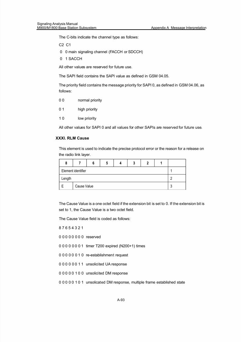
7/30/2019 Signaling Analysis Manual
http://slidepdf.com/reader/full/signaling-analysis-manual 256/290
Signaling Analysis ManualM900/M1800 Base Station Subsystem Appendix A Message Interpretation
A-93
The C-bits indicate the channel type as follows:
C2 C1
0 0 main signaling channel (FACCH or SDCCH)
0 1 SACCH
All other values are reserved for future use.
The SAPI field contains the SAPI value as defined in GSM 04.05.
The priority field contains the message priority for SAPI 0, as defined in GSM 04.06, as
follows:
0 0 normal priority
0 1 high priority
1 0 low priority
All other values for SAPI 0 and all values for other SAPIs are reserved for future use.
XXXI. RLM Cause
This element is used to indicate the precise protocol error or the reason for a release on
the radio link layer.
8 7 6 5 4 3 2 1
Element identifier 1
Length 2
E Cause Value 3
The Cause Value is a one octet field if the extension bit is set to 0. If the extension bit is
set to 1, the Cause Value is a two octet field.
The Cause Value field is coded as follows:
8 7 6 5 4 3 2 1
0 0 0 0 0 0 0 0 reserved
0 0 0 0 0 0 0 1 timer T200 expired (N200+1) times
0 0 0 0 0 0 1 0 re-establishment request
0 0 0 0 0 0 1 1 unsolicited UA response
0 0 0 0 0 1 0 0 unsolicited DM response
0 0 0 0 0 1 0 1 unsolicated DM response, multiple frame established state
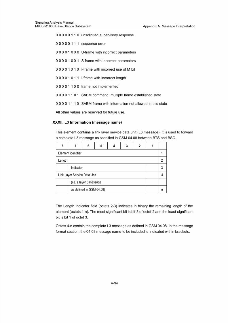
7/30/2019 Signaling Analysis Manual
http://slidepdf.com/reader/full/signaling-analysis-manual 257/290
Signaling Analysis ManualM900/M1800 Base Station Subsystem Appendix A Message Interpretation
A-94
0 0 0 0 0 1 1 0 unsolicited supervisory response
0 0 0 0 0 1 1 1 sequence error
0 0 0 0 1 0 0 0 U-frame with incorrect parameters
0 0 0 0 1 0 0 1 S-frame with incorrect parameters
0 0 0 0 1 0 1 0 I-frame with incorrect use of M bit
0 0 0 0 1 0 1 1 I-frame with incorrect length
0 0 0 0 1 1 0 0 frame not implemented
0 0 0 0 1 1 0 1 SABM command, multiple frame established state
0 0 0 0 1 1 1 0 SABM frame with information not allowed in this state
All other values are reserved for future use.
XXXII. L3 Information (message name)
This element contains a link layer service data unit (L3 message). It is used to forward
a complete L3 message as specified in GSM 04.08 between BTS and BSC.
8 7 6 5 4 3 2 1
Element identifier 1
Length 2
Indicator 3
Link Layer Service Data Unit 4
(i.e. a layer 3 message
as defined in GSM 04.08) n
The Length Indicator field (octets 2-3) indicates in binary the remaining length of the
element (octets 4-n). The most significant bit is bit 8 of octet 2 and the least significant
bit is bit 1 of octet 3.
Octets 4-n contain the complete L3 message as defined in GSM 04.08. In the message
format section, the 04.08 message name to be included is indicated within brackets.
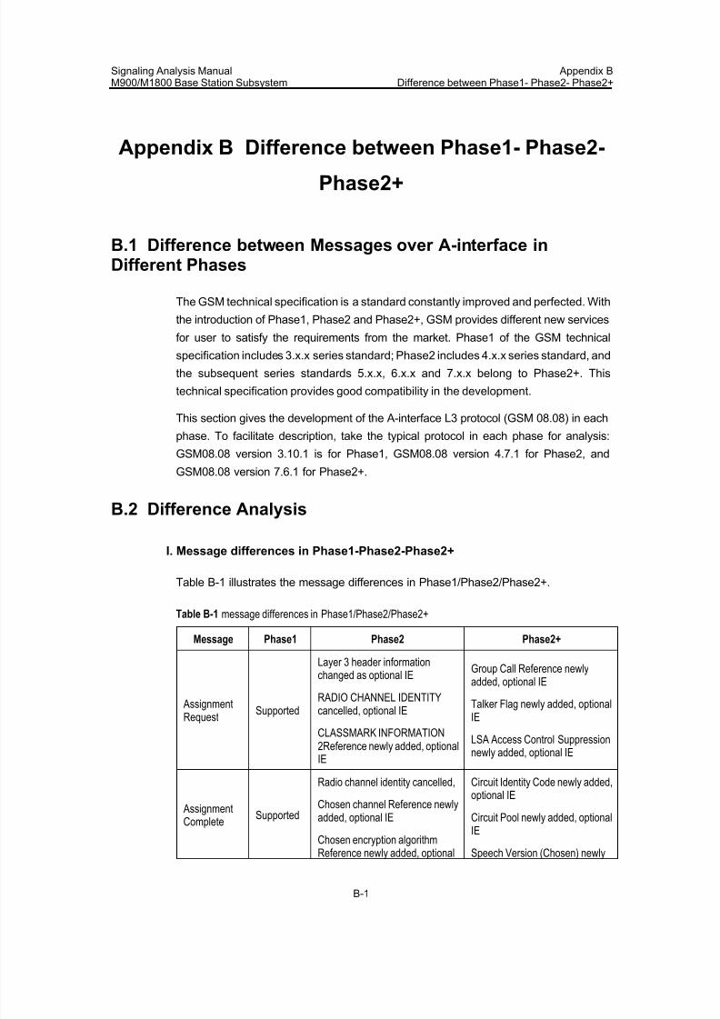
7/30/2019 Signaling Analysis Manual
http://slidepdf.com/reader/full/signaling-analysis-manual 258/290
Signaling Analysis ManualM900/M1800 Base Station Subsystem
Appendix BDifference between Phase1- Phase2- Phase2+
B-1
Appendix B Difference between Phase1- Phase2-
Phase2+
B.1 Difference between Messages over A-interface inDifferent Phases
The GSM technical specification is a standard constantly improved and perfected. With
the introduction of Phase1, Phase2 and Phase2+, GSM provides different new services
for user to satisfy the requirements from the market. Phase1 of the GSM technicalspecification includes 3.x.x series standard; Phase2 includes 4.x.x series standard, and
the subsequent series standards 5.x.x, 6.x.x and 7.x.x belong to Phase2+. This
technical specification provides good compatibility in the development.
This section gives the development of the A-interface L3 protocol (GSM 08.08) in each
phase. To facilitate description, take the typical protocol in each phase for analysis:
GSM08.08 version 3.10.1 is for Phase1, GSM08.08 version 4.7.1 for Phase2, and
GSM08.08 version 7.6.1 for Phase2+.
B.2 Difference Analysis
I. Message differences in Phase1-Phase2-Phase2+
Table B-1 illustrates the message differences in Phase1/Phase2/Phase2+.
Table B-1 message differences in Phase1/Phase2/Phase2+
Message Phase1 Phase2 Phase2+
AssignmentRequest
Supported
Layer 3 header information
changed as optional IERADIO CHANNEL IDENTITYcancelled, optional IE
CLASSMARK INFORMATION2Reference newly added, optionalIE
Group Call Reference newly
added, optional IE
Talker Flag newly added, optionalIE
LSA Access Control Suppressionnewly added, optional IE
AssignmentComplete
Supported
Radio channel identity cancelled,
Chosen channel Reference newlyadded, optional IE
Chosen encryption algorithm
Reference newly added, optional
Circuit Identity Code newly added,optional IE
Circuit Pool newly added, optionalIE
Speech Version (Chosen) newly
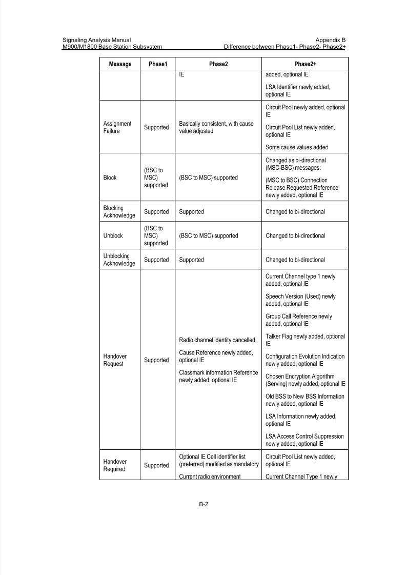
7/30/2019 Signaling Analysis Manual
http://slidepdf.com/reader/full/signaling-analysis-manual 259/290
Signaling Analysis ManualM900/M1800 Base Station Subsystem
Appendix BDifference between Phase1- Phase2- Phase2+
B-2
Message Phase1 Phase2 Phase2+
IE added, optional IE
LSA Identifier newly added,
optional IE
AssignmentFailure
SupportedBasically consistent, with causevalue adjusted
Circuit Pool newly added, optionalIE
Circuit Pool List newly added,optional IE
Some cause values added
Block(BSC toMSC)supported
(BSC to MSC) supported
Changed as bi-directional(MSC-BSC) messages:
(MSC to BSC) ConnectionRelease Requested Referencenewly added, optional IE
Blocking Acknowledge
Supported Supported Changed to bi-directional
Unblock(BSC toMSC)supported
(BSC to MSC) supported Changed to bi-directional
Unblocking Acknowledge
Supported Supported Changed to bi-directional
Handover Request
Supported
Radio channel identity cancelled,
Cause Reference newly added,optional IE
Classmark information Referencenewly added, optional IE
Current Channel type 1 newlyadded, optional IE
Speech Version (Used) newlyadded, optional IE
Group Call Reference newlyadded, optional IE
Talker Flag newly added, optionalIE
Configuration Evolution Indicationnewly added, optional IE
Chosen Encryption Algorithm
(Serving) newly added, optional IE
Old BSS to New BSS Informationnewly added, optional IE
LSA Information newly added,optional IE
LSA Access Control Suppressionnewly added, optional IE
Handover Required
Supported
Optional IE Cell identifier list(preferred) modified as mandatory
Current radio environment
Circuit Pool List newly added,optional IE
Current Channel Type 1 newly
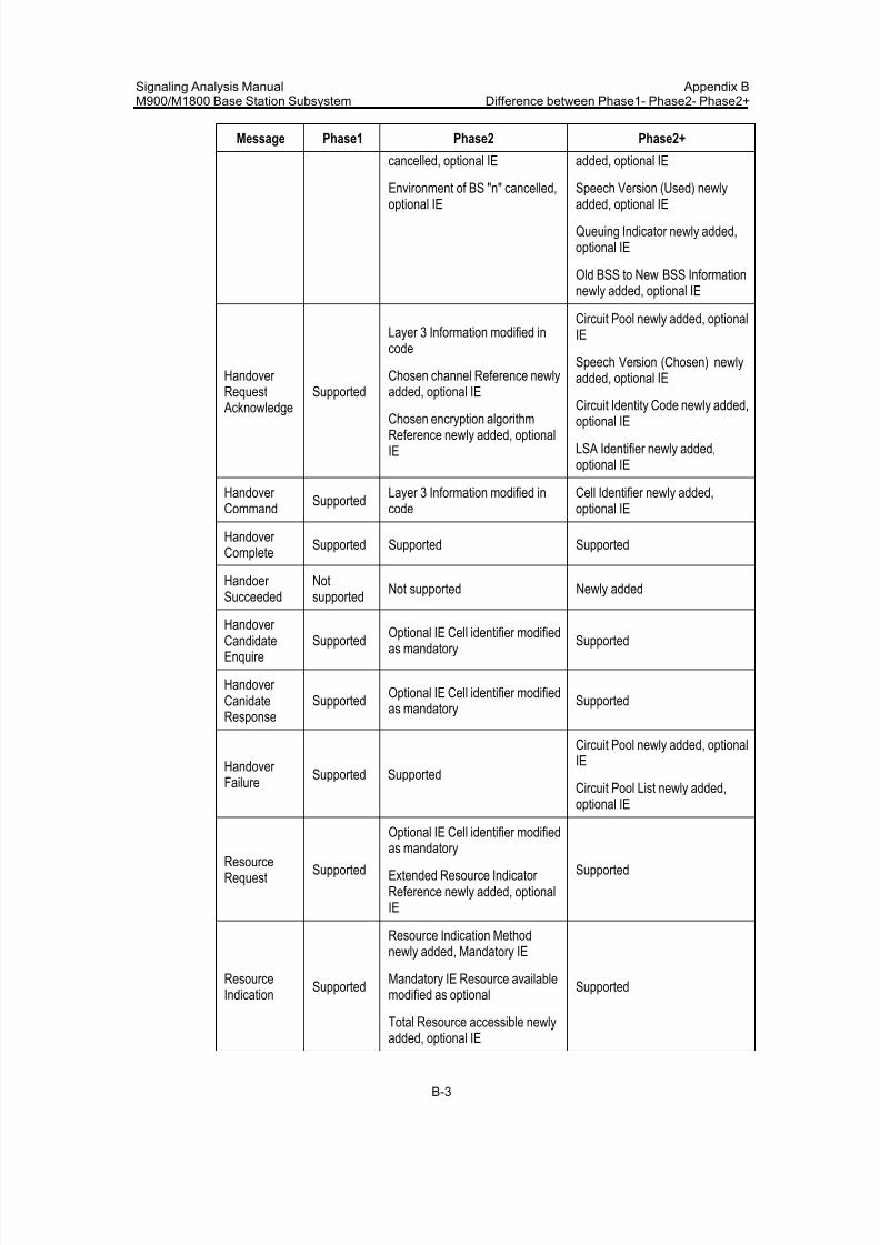
7/30/2019 Signaling Analysis Manual
http://slidepdf.com/reader/full/signaling-analysis-manual 260/290
Signaling Analysis ManualM900/M1800 Base Station Subsystem
Appendix BDifference between Phase1- Phase2- Phase2+
B-3
Message Phase1 Phase2 Phase2+
cancelled, optional IE
Environment of BS "n" cancelled,
optional IE
added, optional IE
Speech Version (Used) newly
added, optional IE
Queuing Indicator newly added,optional IE
Old BSS to New BSS Informationnewly added, optional IE
Handover Request Acknowledge
Supported
Layer 3 Information modified incode
Chosen channel Reference newlyadded, optional IE
Chosen encryption algorithmReference newly added, optionalIE
Circuit Pool newly added, optionalIE
Speech Version (Chosen) newlyadded, optional IE
Circuit Identity Code newly added,optional IE
LSA Identifier newly added,optional IE
Handover Command
SupportedLayer 3 Information modified incode
Cell Identifier newly added,optional IE
Handover Complete
Supported Supported Supported
Handoer Succeeded
Notsupported
Not supported Newly added
Handover CandidateEnquire
SupportedOptional IE Cell identifier modifiedas mandatory
Supported
Handover CanidateResponse
SupportedOptional IE Cell identifier modifiedas mandatory
Supported
Handover Failure
Supported Supported
Circuit Pool newly added, optionalIE
Circuit Pool List newly added,optional IE
ResourceRequest
Supported
Optional IE Cell identifier modifiedas mandatory
Extended Resource Indicator Reference newly added, optionalIE
Supported
ResourceIndication
Supported
Resource Indication Methodnewly added, Mandatory IE
Mandatory IE Resource availablemodified as optional
Total Resource accessible newly
added, optional IE
Supported
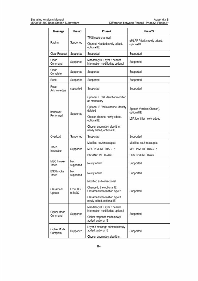
7/30/2019 Signaling Analysis Manual
http://slidepdf.com/reader/full/signaling-analysis-manual 261/290
Signaling Analysis ManualM900/M1800 Base Station Subsystem
Appendix BDifference between Phase1- Phase2- Phase2+
B-4
Message Phase1 Phase2 Phase2+
Paging Supported
TMSI code changed
Channel Needed newly added,
optional IE
eMLPP Priority newly added,optional IE
Clear Request Supported Supported Supported
Clear Command
SupportedMandatory IE Layer 3 header information modified as optional
Supported
Clear Complete
Supported Supported Supported
Reset Supported Supported Supported
Reset Acknowledge
supported Supported Supported
handover Performed
Supported
Optional IE Cell identifier modifiedas mandatory
Optional IE Radio channel identitydeleted
Chosen channel newly added,optional IE
Chosen encryption algorithmnewly added, optional IE
Speech Version (Chosen),optional IE
LSA Identifier newly added
Overload Supported Supported Supported
TraceInvocation
Supported
Modified as 2 messages:
MSC INVOKE TRACE ;
BSS INVOKE TRACE
Modified as 2 messages:
MSC INVOKE TRACE ;
BSS INVOKE TRACE
MSC InvokeTrace
Notsupported
Newly added Supported
BSS InvokeTrace
Notsupported
Newly added Supported
ClassmarkUpdate
From BSCto MSC
Modified as bi-directional
Change to the optional IEClassmark information type 2
Classmark information type 3newly added, optional IE
Supported
Cipher ModeCommand
Supported
Mandatory IE Layer 3 header information modified as optional
Cipher response mode newlyadded, optional IE
Supported
Cipher ModeComplete
Supported
Layer 3 message contents newlyadded, optional IE
Chosen encryption algorithm
Supported
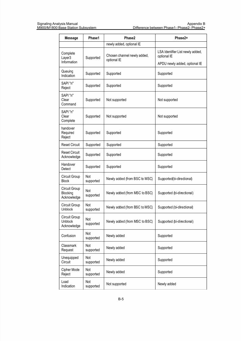
7/30/2019 Signaling Analysis Manual
http://slidepdf.com/reader/full/signaling-analysis-manual 262/290
Signaling Analysis ManualM900/M1800 Base Station Subsystem
Appendix BDifference between Phase1- Phase2- Phase2+
B-5
Message Phase1 Phase2 Phase2+
newly added, optional IE
Complete
Layer3Information
Supported Chosen channel newly added,optional IE
LSA Identifier List newly added,
optional IE
APDU newly added, optional IE
QueuingIndication
Supported Supported Supported
SAPI "n"Reject
Supported Supported Supported
SAPI "n"Clear Command
Supported Not supported Not supported
SAPI "n"Clear Complete
Supported Not supported Not supported
handover RequiredReject
Supported Supported Supported
Reset Circuit Supported Supported Supported
Reset Circuit Acknowledge
Supported Supported Supported
Handover
Detect
Supported Supported Supported
Circuit GroupBlock
Notsupported
Newly added (from BSC to MSC) Supported(bi-directional)
Circuit GroupBlocking Acknowledge
Notsupported
Newly added (from MSC to BSC) Supported (bi-directional)
Circuit GroupUnblock
Notsupported
Newly added (from BSC to MSC) Supported (bi-directional)
Circuit GroupUnblock
Acknowledge
Notsupported
Newly added (from MSC to BSC) Supported (bi-directional)
ConfusionNotsupported
Newly added Supported
ClassmarkRequest
Notsupported
Newly added Supported
UnequippedCircuit
Notsupported
Newly added Supported
Cipher ModeReject
Notsupported
Newly added Supported
Load
Indication
Not
supported Not supported Newly added
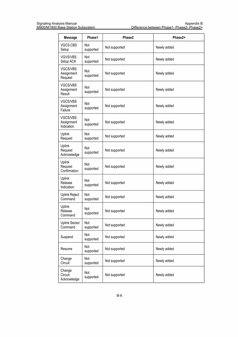
7/30/2019 Signaling Analysis Manual
http://slidepdf.com/reader/full/signaling-analysis-manual 263/290
Signaling Analysis ManualM900/M1800 Base Station Subsystem
Appendix BDifference between Phase1- Phase2- Phase2+
B-6
Message Phase1 Phase2 Phase2+
VGCS.CBSSetup
Notsupported
Not supported Newly added
VGVS/VBSSetup ACK
Notsupported
Not supported Newly added
VGCS/VBS AssignmentRequest
Notsupported
Not supported Newly added
VGCS/VBS AssignmentResult
Notsupported
Not supported Newly added
VGCS/VBS AssignmentFailure
Notsupported
Not supported Newly added
VGCS/VBS AssignmentIndication
Notsupported
Not supported Newly added
UplinkRequest
Notsupported
Not supported Newly added
UplinkRequest Acknowledge
Notsupported
Not supported Newly added
UplinkRequestConfirmation
Not
supportedNot supported Newly added
UplinkReleaseIndication
Notsupported
Not supported Newly added
Uplink RejectCommand
Notsupported
Not supported Newly added
UplinkReleaseCommand
Notsupported
Not supported Newly added
Uplink SeizedCommand
Notsupported Not supported Newly added
SuspendNotsupported
Not supported Newly added
ResumeNotsupported
Not supported Newly added
ChangeCircuit
Notsupported
Not supported Newly added
ChangeCircuit Acknowledge
Notsupported
Not supported Newly added
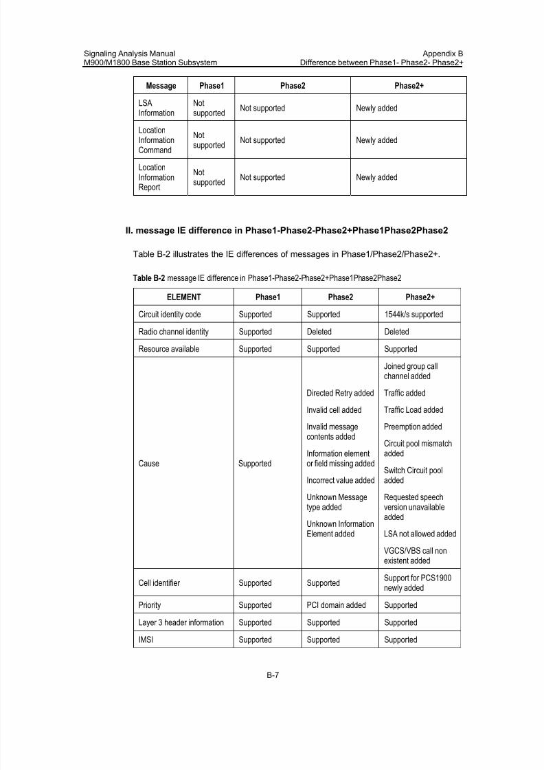
7/30/2019 Signaling Analysis Manual
http://slidepdf.com/reader/full/signaling-analysis-manual 264/290
Signaling Analysis ManualM900/M1800 Base Station Subsystem
Appendix BDifference between Phase1- Phase2- Phase2+
B-7
Message Phase1 Phase2 Phase2+
LSAInformation
Notsupported
Not supported Newly added
LocationInformationCommand
Notsupported
Not supported Newly added
LocationInformationReport
Notsupported
Not supported Newly added
II. message IE difference in Phase1-Phase2-Phase2+Phase1Phase2Phase2
Table B-2 illustrates the IE differences of messages in Phase1/Phase2/Phase2+.
Table B-2 message IE difference in Phase1-Phase2-Phase2+Phase1Phase2Phase2
ELEMENT Phase1 Phase2 Phase2+
Circuit identity code Supported Supported 1544k/s supported
Radio channel identity Supported Deleted Deleted
Resource available Supported Supported Supported
Cause Supported
Directed Retry added
Invalid cell added
Invalid messagecontents added
Information elementor field missing added
Incorrect value added
Unknown Messagetype added
Unknown InformationElement added
Joined group callchannel added
Traffic added
Traffic Load added
Preemption added
Circuit pool mismatchadded
Switch Circuit pooladded
Requested speechversion unavailable
added
LSA not allowed added
VGCS/VBS call nonexistent added
Cell identifier Supported SupportedSupport for PCS1900newly added
Priority Supported PCI domain added Supported
Layer 3 header information Supported Supported Supported
IMSI Supported Supported Supported
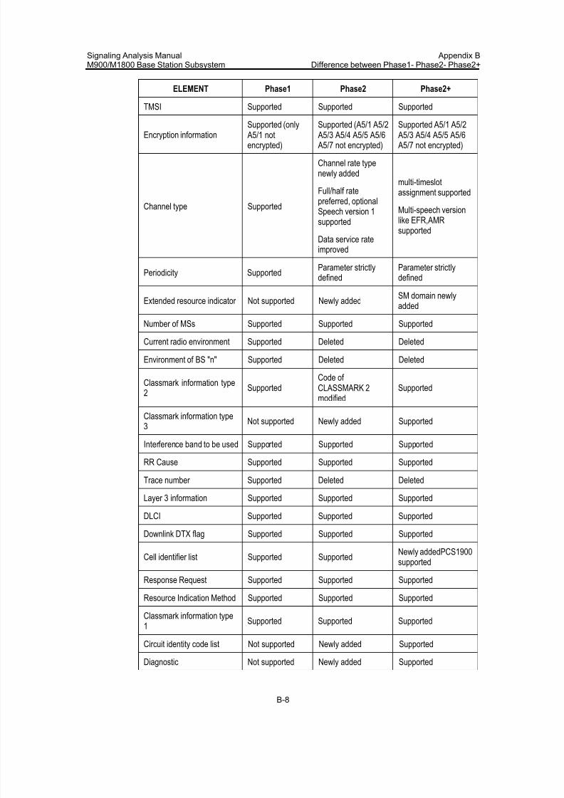
7/30/2019 Signaling Analysis Manual
http://slidepdf.com/reader/full/signaling-analysis-manual 265/290
Signaling Analysis ManualM900/M1800 Base Station Subsystem
Appendix BDifference between Phase1- Phase2- Phase2+
B-8
ELEMENT Phase1 Phase2 Phase2+
TMSI Supported Supported Supported
Encryption information
Supported (only
A5/1 notencrypted)
Supported (A5/1 A5/2
A5/3 A5/4 A5/5 A5/6 A5/7 not encrypted)
Supported A5/1 A5/2
A5/3 A5/4 A5/5 A5/6 A5/7 not encrypted)
Channel type Supported
Channel rate typenewly added
Full/half ratepreferred, optionalSpeech version 1supported
Data service rateimproved
multi-timeslotassignment supported
Multi-speech versionlike EFR,AMRsupported
Periodicity Supported Parameter strictlydefined
Parameter strictlydefined
Extended resource indicator Not supported Newly addedSM domain newlyadded
Number of MSs Supported Supported Supported
Current radio environment Supported Deleted Deleted
Environment of BS "n" Supported Deleted Deleted
Classmark information type2
SupportedCode of CLASSMARK 2
modified
Supported
Classmark information type3
Not supported Newly added Supported
Interference band to be used Supported Supported Supported
RR Cause Supported Supported Supported
Trace number Supported Deleted Deleted
Layer 3 information Supported Supported Supported
DLCI Supported Supported Supported
Downlink DTX flag Supported Supported Supported
Cell identifier list Supported SupportedNewly addedPCS1900supported
Response Request Supported Supported Supported
Resource Indication Method Supported Supported Supported
Classmark information type1
Supported Supported Supported
Circuit identity code list Not supported Newly added Supported
Diagnostic Not supported Newly added Supported
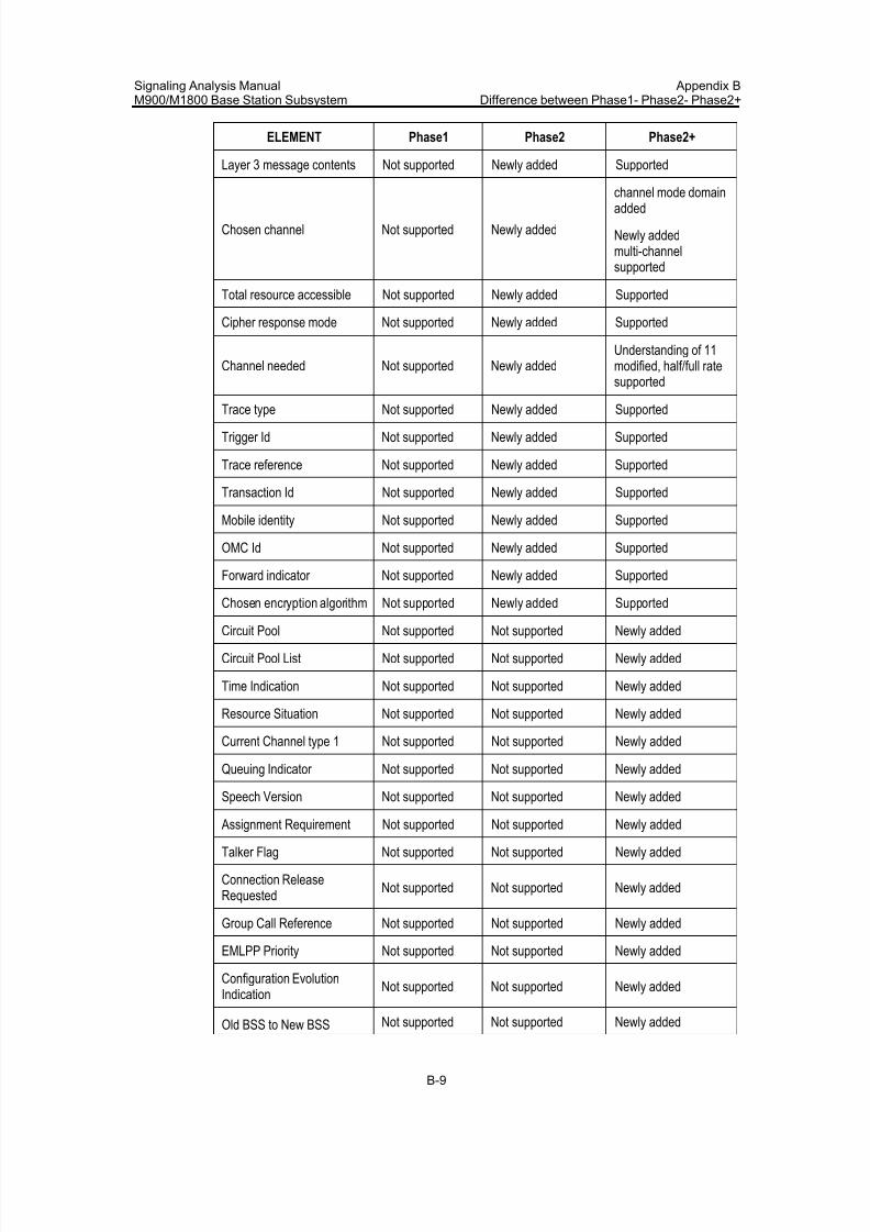
7/30/2019 Signaling Analysis Manual
http://slidepdf.com/reader/full/signaling-analysis-manual 266/290
Signaling Analysis ManualM900/M1800 Base Station Subsystem
Appendix BDifference between Phase1- Phase2- Phase2+
B-9
ELEMENT Phase1 Phase2 Phase2+
Layer 3 message contents Not supported Newly added Supported
Chosen channel Not supported Newly added
channel mode domain
added
Newly addedmulti-channelsupported
Total resource accessible Not supported Newly added Supported
Cipher response mode Not supported Newly added Supported
Channel needed Not supported Newly addedUnderstanding of 11modified, half/full ratesupported
Trace type Not supported Newly added Supported
Trigger Id Not supported Newly added Supported
Trace reference Not supported Newly added Supported
Transaction Id Not supported Newly added Supported
Mobile identity Not supported Newly added Supported
OMC Id Not supported Newly added Supported
Forward indicator Not supported Newly added Supported
Chosen encryption algorithm Not supported Newly added Supported
Circuit Pool Not supported Not supported Newly added
Circuit Pool List Not supported Not supported Newly added
Time Indication Not supported Not supported Newly added
Resource Situation Not supported Not supported Newly added
Current Channel type 1 Not supported Not supported Newly added
Queuing Indicator Not supported Not supported Newly added
Speech Version Not supported Not supported Newly added
Assignment Requirement Not supported Not supported Newly added
Talker Flag Not supported Not supported Newly added
Connection ReleaseRequested
Not supported Not supported Newly added
Group Call Reference Not supported Not supported Newly added
EMLPP Priority Not supported Not supported Newly added
Configuration EvolutionIndication
Not supported Not supported Newly added
Old BSS to New BSS Not supported Not supported Newly added
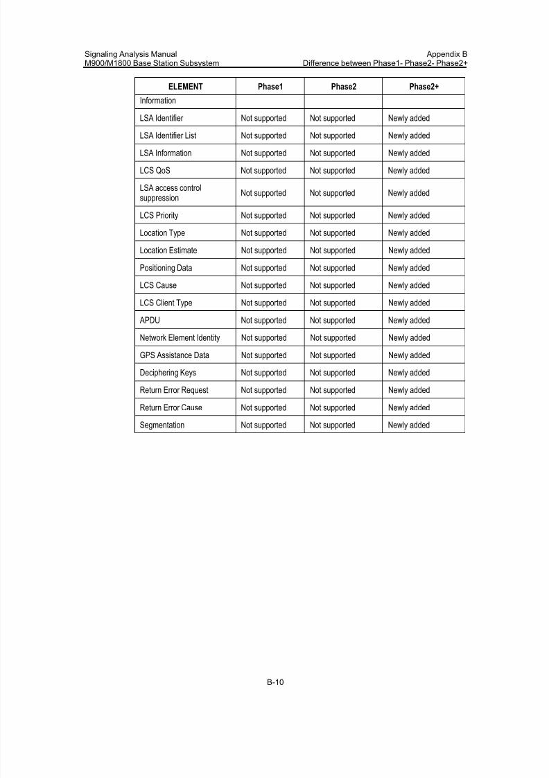
7/30/2019 Signaling Analysis Manual
http://slidepdf.com/reader/full/signaling-analysis-manual 267/290
Signaling Analysis ManualM900/M1800 Base Station Subsystem
Appendix BDifference between Phase1- Phase2- Phase2+
B-10
ELEMENT Phase1 Phase2 Phase2+
Information
LSA Identifier Not supported Not supported Newly added
LSA Identifier List Not supported Not supported Newly added
LSA Information Not supported Not supported Newly added
LCS QoS Not supported Not supported Newly added
LSA access controlsuppression
Not supported Not supported Newly added
LCS Priority Not supported Not supported Newly added
Location Type Not supported Not supported Newly added
Location Estimate Not supported Not supported Newly added
Positioning Data Not supported Not supported Newly added
LCS Cause Not supported Not supported Newly added
LCS Client Type Not supported Not supported Newly added
APDU Not supported Not supported Newly added
Network Element Identity Not supported Not supported Newly added
GPS Assistance Data Not supported Not supported Newly added
Deciphering Keys Not supported Not supported Newly added
Return Error Request Not supported Not supported Newly added
Return Error Cause Not supported Not supported Newly added
Segmentation Not supported Not supported Newly added
7/30/2019 Signaling Analysis Manual
http://slidepdf.com/reader/full/signaling-analysis-manual 268/290
7/30/2019 Signaling Analysis Manual
http://slidepdf.com/reader/full/signaling-analysis-manual 269/290
Signaling Analysis ManualM900/M1800 Base Station Subsystem Appendix C Glossary
C-2
CBS Cell Broadcast Service
CC Call Control
CCCH Common Control Channel
CCH Control channel
CCITT International Telegraph and Telephone Consultative Committee
CCS Common Channel Signaling
CGI Cell Global Identification
CI Cell Identity
CIC Circuit Identification Code
CKSN Circuit Identification Code
CM Connection ManagementCP
CR Connection Request
CRC Cyclic Redundancy Code
CRO Cell Reselect Offset
D
DCCH Dedicated Control CHannel
DCS Digital Cellular System
DLC Data Link Connection
DLCEP Data Link Connection End Point
DLCI Data Link Connection Identifier
DM Disconnected Mode
DPC Destination Point Code
DRX Discontinuous Reception
DTAP Direct Transfer Application Part
DTMF Dual-Tone Multi-frequency
DTX Discontinuous Transmission
E
E3M E3 Sub-Multiplexer
EC Emergency Call
ECSC Early Classmark Sending Control
EFR Enhanced full rate speech codec
eMLPP Environment Monitoring
ETSI European Telecommunications Standards Institute
7/30/2019 Signaling Analysis Manual
http://slidepdf.com/reader/full/signaling-analysis-manual 270/290
Signaling Analysis ManualM900/M1800 Base Station Subsystem Appendix C Glossary
C-3
F
FACCH Fast Associated Control Channel
FN Frame Number
FR Full Rate
FUC Frame Unit Controller
G
GFBI Fiber Interface board
GMC2 Inter-Module Communication board
GMCC Module Communication and Control board
GOPT Local Optical Interface Board
GPRS General Packet Radio ServiceGPS Global Position System
GSM Global System for Mobile Communications
GSNT GSM Signaling Switching Network Board
GT Global Title
H
HLR Home Location Register
HR Half Rate
HSCSD High Speed Circuit Switched Data
I
ID IDentification/IDentity
IE information element
IMEI International Mobile Equipment Identity
IMSI International Mobile Station Identity
ISDN Integrated Services Digital Network
ISUP Integrated Services Digital Network User Part/ISDN User Part
ITU-T International Telecommunication Union - Telecommunication StandardizationSector
L
L2ML Layer 2 Management Link
LAC Location Area Code
LAI Location Area Identity
LAPD Link Access Procedure on the D channel
LAPDm Link Access Procedure on the Dm channel
7/30/2019 Signaling Analysis Manual
http://slidepdf.com/reader/full/signaling-analysis-manual 271/290
Signaling Analysis ManualM900/M1800 Base Station Subsystem Appendix C Glossary
C-4
LCS LoCation Service
LPN7 Common Channel Signaling Processing Board
LSA Link State Advertisement
LSB Least Significant Bit
M
MA Mobile Allocation
MACS Maximum number of AMR Codec ModeS
MAP Mobile Application Part
MCC Mobile Country Code
MDC Message Discrimination
MDT Message DistributionME Mobile Equipment
MM Mobility Management
MMCC Mobility Management Call Control
MMSMS Mobility Management Short Message Service
MMSS Mobility Management Supplement Service
MNC Mobile Network Code
MNS Mobile Network Signaling
MOC Mobile Originated Call
MRT Message Routing
MS Mobile Station
MSB. Most Significant Bit
MSC Mobile Switching Center, Mobile Service Switching Center
MSU Message Signaling Unit
MT Maintenance and Test console
MTP Message Transfer Part
N
NA No Acknowledgment
NACK Negative ACKnowledgement
NCC Network Color Code
NECI New Establishment Causes Indication
NI Network Identity
NSS Network SubSystem
O
7/30/2019 Signaling Analysis Manual
http://slidepdf.com/reader/full/signaling-analysis-manual 272/290
Signaling Analysis ManualM900/M1800 Base Station Subsystem Appendix C Glossary
C-5
OACSU Off Air Call Set Up
OM Operation & Maintenance
OMAP Operation and Maintenance Application Part
OMC Operation and Maintenance Center
OML Operation & Maintenance Link
OPC Originating Point Code
OSI Open System(s) Interconnection
P
PCH Open System(s) Interconnection
PCI Protocol Control Information
PCM Pulse Code ModulationPCS Personal Communications Services
PD Discrimination
PHY Physical Sublayer & Physical Layer
PI cell reselection Parameter Indication
PLMN Public Land Mobile Network
PT Penalty Time
PWRC Power Control
Q
QoS Quality of Service
R
RA Random Access
RACH Random Access CHannel
RAND RANDom number
RF Radio Frequency
RIL3 Radio Interface Layer 3
RLM Radio Link Management
RR Radio Resource
RSL Radio Signaling Link
RXLEV received signal level
RXQUAL received Signal Quality
S
SABM Set Asynchronous Balanced Mode
SACCH Slow Associated Control CHannel
7/30/2019 Signaling Analysis Manual
http://slidepdf.com/reader/full/signaling-analysis-manual 273/290
Signaling Analysis ManualM900/M1800 Base Station Subsystem Appendix C Glossary
C-6
SAP Service Access Point
SAPI Service Access Point Identification
SCCP Signaling Connection and Control Part
SCMG SCCP Management
SCS Set of AMR Codec modes Supported
SDCCH Stand-alone Dedicated Control Channel
SI Service Indicator
SIM Subscriber Identity Module
SLC Signaling Link Code
SLM Signaling Link Manager
SLS Signaling Link SelectionSLT Signaling Link Test
SM Session Management
SMI Subsequent Modification Indication
SMLC Serving Mobile Location Center
SMS Short Message Service
SNM Signaling Network Management
SRES Signed Response
SRM Signaling Route Management
SS Supplementary Service
SS7 Signaling System No.7
SSN Sub-System Number
STM Signaling Traffic Management
T
TA Timing Advance
TCAP Transaction Capabilities Application Part
TCH Traffic Channel
TCSM Transcoder and Sub-Multiplexer
TDMA Time Division Multiple Access
TEI Terminal Endpoint Identification
TFO Tandem Free Operation
TI Transaction Identifier
TMSI Temp Mobile Subscriber Identifier
TN Time slot Number

7/30/2019 Signaling Analysis Manual
http://slidepdf.com/reader/full/signaling-analysis-manual 274/290
Signaling Analysis ManualM900/M1800 Base Station Subsystem Appendix C Glossary
C-7
TRX Transceiver
TS technical specification(s)
TUP Telephone User Part
U
UA Unnumbered Acknowledge
UI Unnumbered Information(frame)
V
VBS Voice Broadcast Service
VGCS Voice Group Call Service
VLR Visitor Location Register
7/30/2019 Signaling Analysis Manual
http://slidepdf.com/reader/full/signaling-analysis-manual 275/290
Signaling Analysis ManualM900/M1800 Base Station Subsystem Appendix D Abbreviation
D-1
Appendix D Abbreviation
A
ACC Accept
ACK Acknowledgement
ACT Activation
ACTIV Activation
ASS Assignment
AUT Authentication
C
CHAN Channel
CIPH Ciphering
CMD Command
CMP Complete
CNF Confirm
CONF Confirm
CONN Connection
D
DEACT Deactivation
DET Detection
DISC Disconnect
E
ENCR Encryption
EST Establishment
EXT Extended
H
HANDO Handover
7/30/2019 Signaling Analysis Manual
http://slidepdf.com/reader/full/signaling-analysis-manual 276/290
Signaling Analysis ManualM900/M1800 Base Station Subsystem Appendix D Abbreviation
D-2
I
IMM Immediate
IND Indication
INFO Information
L
L3 Layer 3
LOC Location
M
MOD Mode
P
PAG Paging
PHY Physical
R
REJ Reject
REL Release
RES Resource
REQ Request
RLSD Released
RPS Response
RQD Required
S
SERV Service
U
UPD Updating
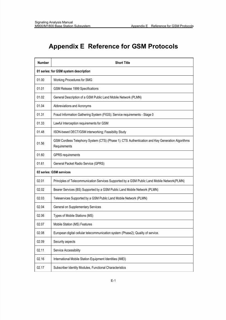
7/30/2019 Signaling Analysis Manual
http://slidepdf.com/reader/full/signaling-analysis-manual 277/290
Signaling Analysis ManualM900/M1800 Base Station Subsystem Appendix E Reference for GSM Protocols
E-1
Appendix E Reference for GSM Protocols
Number Short Title
01 series: for GSM system description
01.00 Working Procedures for SMG
01.01 GSM Release 1999 Specifications
01.02 General Description of a GSM Public Land Mobile Network (PLMN)
01.04 Abbreviations and Acronyms
01.31 Fraud Information Gathering System (FIGS); Service requirements - Stage 0
01.33 Lawful Interception requirements for GSM
01.48 ISDN-based DECT/GSM interworking; Feasibility Study
01.56GSM Cordless Telephony System (CTS) (Phase 1); CTS Authentication and Key Generation Algorithms
Requirements
01.60 GPRS requirements
01.61 General Packet Radio Service (GPRS)
02 series: GSM services
02.01 Principles of Telecommunication Services Supported by a GSM Public Land Mobile Network(PLMN)
02.02 Bearer Services (BS) Supported by a GSM Public Land Mobile Network (PLMN)
02.03 Teleservices Supported by a GSM Public Land Mobile Network (PLMN)
02.04 General on Supplementary Services
02.06 Types of Mobile Stations (MS)
02.07 Mobile Station (MS) Features
02.08 European digital cellular telecommunication system (Phase2); Quality of service.
02.09 Security aspects
02.11 Service Accessibility
02.16 International Mobile Station Equipment Identities (IMEI)
02.17 Subscriber Identity Modules, Functional Characteristics
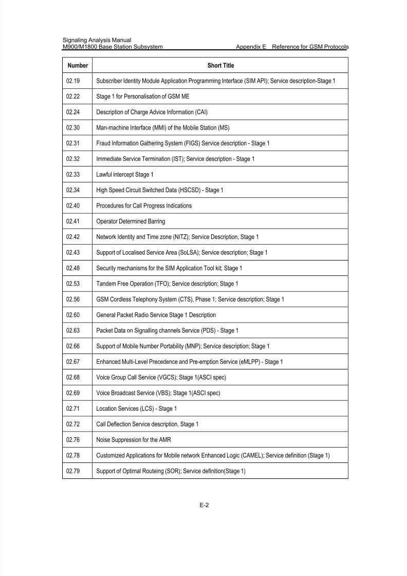
7/30/2019 Signaling Analysis Manual
http://slidepdf.com/reader/full/signaling-analysis-manual 278/290
Signaling Analysis ManualM900/M1800 Base Station Subsystem Appendix E Reference for GSM Protocols
E-2
Number Short Title
02.19 Subscriber Identity Module Application Programming Interface (SIM API); Service description-Stage 1
02.22 Stage 1 for Personalisation of GSM ME
02.24 Description of Charge Advice Information (CAI)
02.30 Man-machine Interface (MMI) of the Mobile Station (MS)
02.31 Fraud Information Gathering System (FIGS) Service description - Stage 1
02.32 Immediate Service Termination (IST); Service description - Stage 1
02.33 Lawful intercept Stage 1
02.34 High Speed Circuit Switched Data (HSCSD) - Stage 1
02.40 Procedures for Call Progress Indications
02.41 Operator Determined Barring
02.42 Network Identity and Time zone (NITZ); Service Description, Stage 1
02.43 Support of Localised Service Area (SoLSA); Service description; Stage 1
02.48 Security mechanisms for the SIM Application Tool kit; Stage 1
02.53 Tandem Free Operation (TFO); Service description; Stage 1
02.56 GSM Cordless Telephony System (CTS), Phase 1; Service description; Stage 1
02.60 General Packet Radio Service Stage 1 Description
02.63 Packet Data on Signalling channels Service (PDS) - Stage 1
02.66 Support of Mobile Number Portability (MNP); Service description; Stage 1
02.67 Enhanced Multi-Level Precedence and Pre-emption Service (eMLPP) - Stage 1
02.68 Voice Group Call Service (VGCS); Stage 1(ASCI spec)
02.69 Voice Broadcast Service (VBS); Stage 1(ASCI spec)
02.71 Location Services (LCS) - Stage 1
02.72 Call Deflection Service description, Stage 1
02.76 Noise Suppression for the AMR
02.78 Customized Applications for Mobile network Enhanced Logic (CAMEL); Service definition (Stage 1)
02.79 Support of Optimal Routeing (SOR); Service definition(Stage 1)
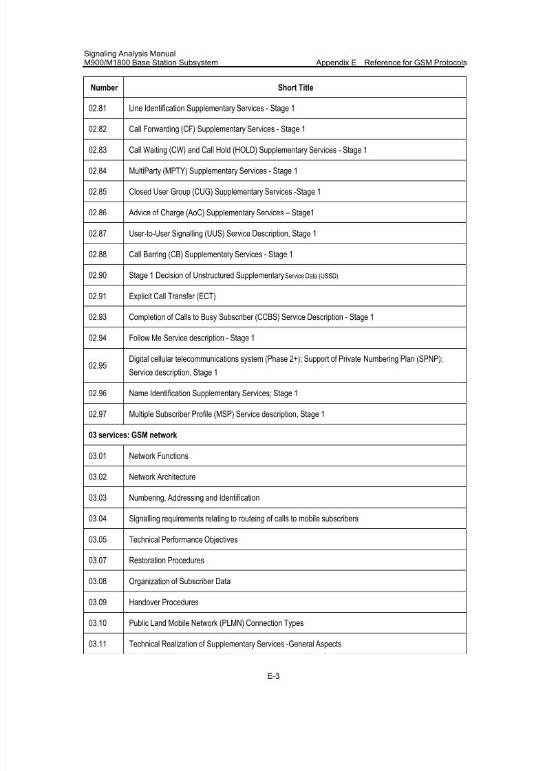
7/30/2019 Signaling Analysis Manual
http://slidepdf.com/reader/full/signaling-analysis-manual 279/290
Signaling Analysis ManualM900/M1800 Base Station Subsystem Appendix E Reference for GSM Protocols
E-3
Number Short Title
02.81 Line Identification Supplementary Services - Stage 1
02.82 Call Forwarding (CF) Supplementary Services - Stage 1
02.83 Call Waiting (CW) and Call Hold (HOLD) Supplementary Services - Stage 1
02.84 MultiParty (MPTY) Supplementary Services - Stage 1
02.85 Closed User Group (CUG) Supplementary Services -Stage 1
02.86 Advice of Charge (AoC) Supplementary Services – Stage1
02.87 User-to-User Signalling (UUS) Service Description, Stage 1
02.88 Call Barring (CB) Supplementary Services - Stage 1
02.90 Stage 1 Decision of Unstructured Supplementary Service Data (USSD)
02.91 Explicit Call Transfer (ECT)
02.93 Completion of Calls to Busy Subscriber (CCBS) Service Description - Stage 1
02.94 Follow Me Service description - Stage 1
02.95Digital cellular telecommunications system (Phase 2+); Support of Private Numbering Plan (SPNP);
Service description, Stage 1
02.96 Name Identification Supplementary Services; Stage 1
02.97 Multiple Subscriber Profile (MSP) Service description, Stage 1
03 services: GSM network
03.01 Network Functions
03.02 Network Architecture
03.03 Numbering, Addressing and Identification
03.04 Signalling requirements relating to routeing of calls to mobile subscribers
03.05 Technical Performance Objectives
03.07 Restoration Procedures
03.08 Organization of Subscriber Data
03.09 Handover Procedures
03.10 Public Land Mobile Network (PLMN) Connection Types
03.11 Technical Realization of Supplementary Services -General Aspects
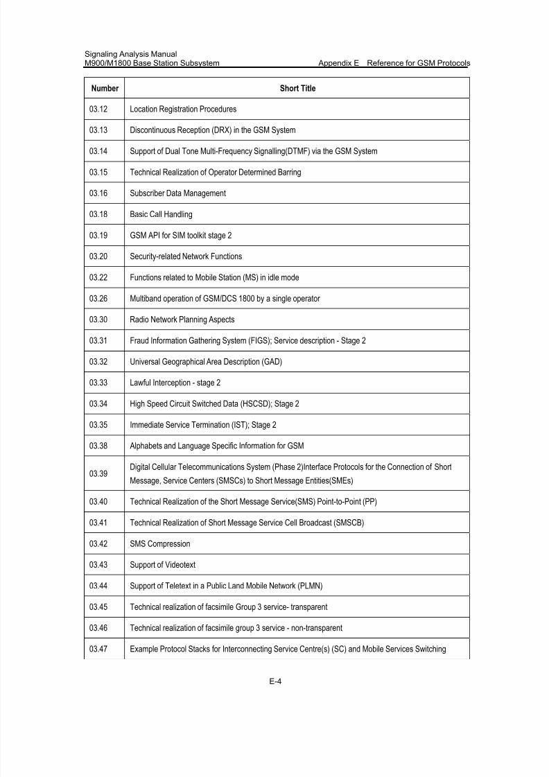
7/30/2019 Signaling Analysis Manual
http://slidepdf.com/reader/full/signaling-analysis-manual 280/290
Signaling Analysis ManualM900/M1800 Base Station Subsystem Appendix E Reference for GSM Protocols
E-4
Number Short Title
03.12 Location Registration Procedures
03.13 Discontinuous Reception (DRX) in the GSM System
03.14 Support of Dual Tone Multi-Frequency Signalling(DTMF) via the GSM System
03.15 Technical Realization of Operator Determined Barring
03.16 Subscriber Data Management
03.18 Basic Call Handling
03.19 GSM API for SIM toolkit stage 2
03.20 Security-related Network Functions
03.22 Functions related to Mobile Station (MS) in idle mode
03.26 Multiband operation of GSM/DCS 1800 by a single operator
03.30 Radio Network Planning Aspects
03.31 Fraud Information Gathering System (FIGS); Service description - Stage 2
03.32 Universal Geographical Area Description (GAD)
03.33 Lawful Interception - stage 2
03.34 High Speed Circuit Switched Data (HSCSD); Stage 2
03.35 Immediate Service Termination (IST); Stage 2
03.38 Alphabets and Language Specific Information for GSM
03.39Digital Cellular Telecommunications System (Phase 2)Interface Protocols for the Connection of Short
Message, Service Centers (SMSCs) to Short Message Entities(SMEs)
03.40 Technical Realization of the Short Message Service(SMS) Point-to-Point (PP)
03.41 Technical Realization of Short Message Service Cell Broadcast (SMSCB)
03.42 SMS Compression
03.43 Support of Videotext
03.44 Support of Teletext in a Public Land Mobile Network (PLMN)
03.45 Technical realization of facsimile Group 3 service- transparent
03.46 Technical realization of facsimile group 3 service - non-transparent
03.47 Example Protocol Stacks for Interconnecting Service Centre(s) (SC) and Mobile Services Switching
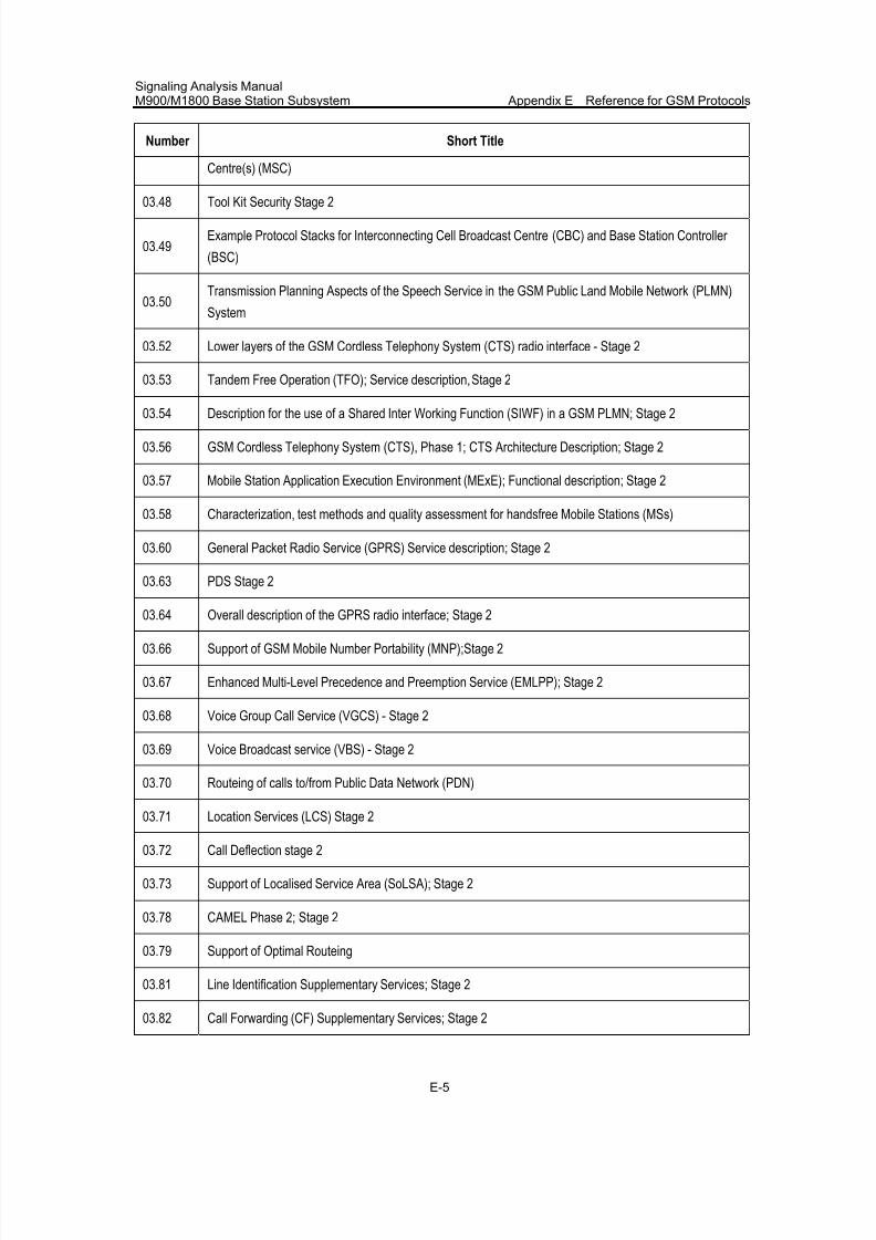
7/30/2019 Signaling Analysis Manual
http://slidepdf.com/reader/full/signaling-analysis-manual 281/290
Signaling Analysis ManualM900/M1800 Base Station Subsystem Appendix E Reference for GSM Protocols
E-5
Number Short Title
Centre(s) (MSC)
03.48 Tool Kit Security Stage 2
03.49Example Protocol Stacks for Interconnecting Cell Broadcast Centre (CBC) and Base Station Controller
(BSC)
03.50Transmission Planning Aspects of the Speech Service in the GSM Public Land Mobile Network (PLMN)
System
03.52 Lower layers of the GSM Cordless Telephony System (CTS) radio interface - Stage 2
03.53 Tandem Free Operation (TFO); Service description, Stage 2
03.54 Description for the use of a Shared Inter Working Function (SIWF) in a GSM PLMN; Stage 2
03.56 GSM Cordless Telephony System (CTS), Phase 1; CTS Architecture Description; Stage 2
03.57 Mobile Station Application Execution Environment (MExE); Functional description; Stage 2
03.58 Characterization, test methods and quality assessment for handsfree Mobile Stations (MSs)
03.60 General Packet Radio Service (GPRS) Service description; Stage 2
03.63 PDS Stage 2
03.64 Overall description of the GPRS radio interface; Stage 2
03.66 Support of GSM Mobile Number Portability (MNP);Stage 2
03.67 Enhanced Multi-Level Precedence and Preemption Service (EMLPP); Stage 2
03.68 Voice Group Call Service (VGCS) - Stage 2
03.69 Voice Broadcast service (VBS) - Stage 2
03.70 Routeing of calls to/from Public Data Network (PDN)
03.71 Location Services (LCS) Stage 2
03.72 Call Deflection stage 2
03.73 Support of Localised Service Area (SoLSA); Stage 2
03.78 CAMEL Phase 2; Stage 2
03.79 Support of Optimal Routeing
03.81 Line Identification Supplementary Services; Stage 2
03.82 Call Forwarding (CF) Supplementary Services; Stage 2
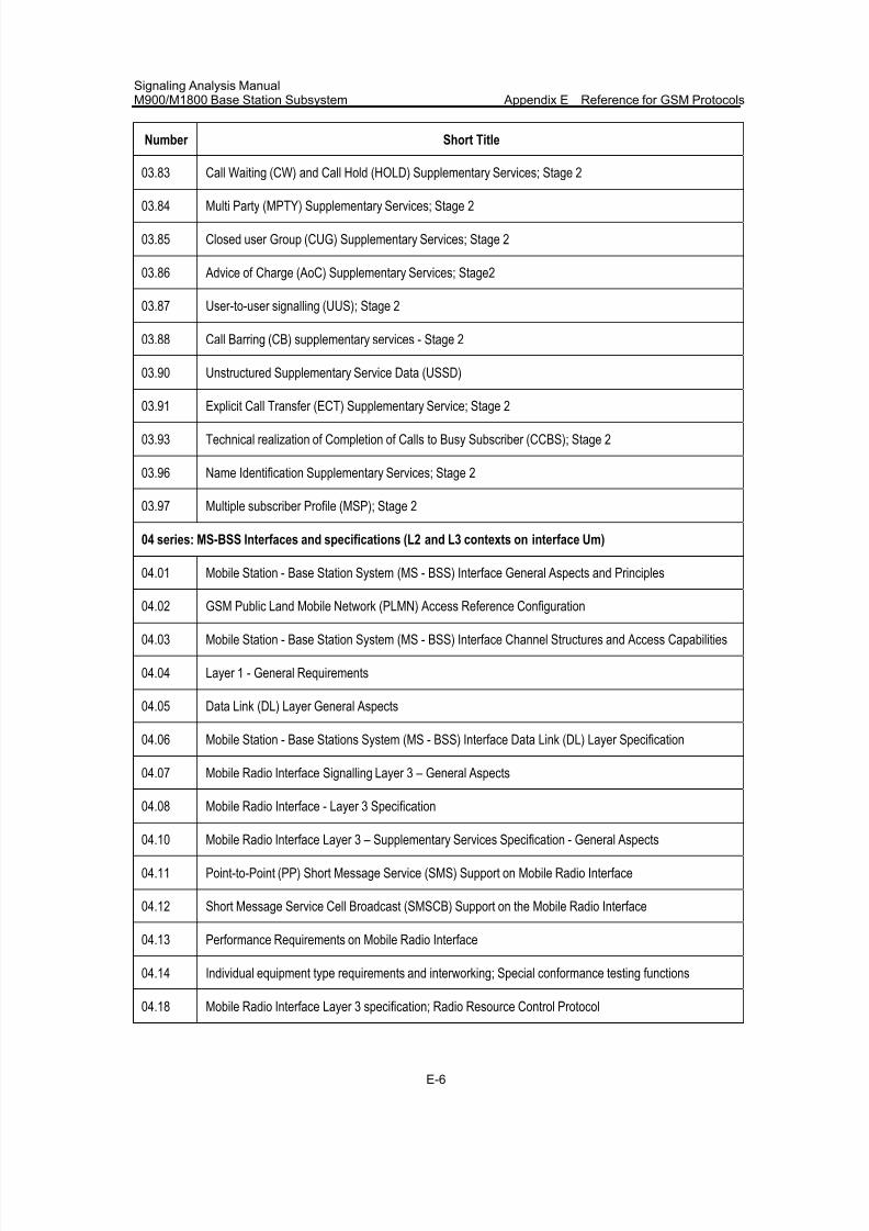
7/30/2019 Signaling Analysis Manual
http://slidepdf.com/reader/full/signaling-analysis-manual 282/290
Signaling Analysis ManualM900/M1800 Base Station Subsystem Appendix E Reference for GSM Protocols
E-6
Number Short Title
03.83 Call Waiting (CW) and Call Hold (HOLD) Supplementary Services; Stage 2
03.84 Multi Party (MPTY) Supplementary Services; Stage 2
03.85 Closed user Group (CUG) Supplementary Services; Stage 2
03.86 Advice of Charge (AoC) Supplementary Services; Stage2
03.87 User-to-user signalling (UUS); Stage 2
03.88 Call Barring (CB) supplementary services - Stage 2
03.90 Unstructured Supplementary Service Data (USSD)
03.91 Explicit Call Transfer (ECT) Supplementary Service; Stage 2
03.93 Technical realization of Completion of Calls to Busy Subscriber (CCBS); Stage 2
03.96 Name Identification Supplementary Services; Stage 2
03.97 Multiple subscriber Profile (MSP); Stage 2
04 series: MS-BSS Interfaces and specifications (L2 and L3 contexts on interface Um)
04.01 Mobile Station - Base Station System (MS - BSS) Interface General Aspects and Principles
04.02 GSM Public Land Mobile Network (PLMN) Access Reference Configuration
04.03 Mobile Station - Base Station System (MS - BSS) Interface Channel Structures and Access Capabilities
04.04 Layer 1 - General Requirements
04.05 Data Link (DL) Layer General Aspects
04.06 Mobile Station - Base Stations System (MS - BSS) Interface Data Link (DL) Layer Specification
04.07 Mobile Radio Interface Signalling Layer 3 – General Aspects
04.08 Mobile Radio Interface - Layer 3 Specification
04.10 Mobile Radio Interface Layer 3 – Supplementary Services Specification - General Aspects
04.11 Point-to-Point (PP) Short Message Service (SMS) Support on Mobile Radio Interface
04.12 Short Message Service Cell Broadcast (SMSCB) Support on the Mobile Radio Interface
04.13 Performance Requirements on Mobile Radio Interface
04.14 Individual equipment type requirements and interworking; Special conformance testing functions
04.18 Mobile Radio Interface Layer 3 specification; Radio Resource Control Protocol
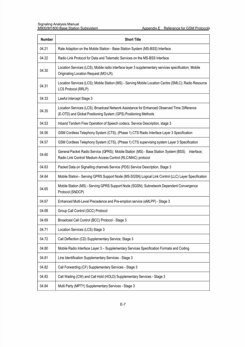
7/30/2019 Signaling Analysis Manual
http://slidepdf.com/reader/full/signaling-analysis-manual 283/290
Signaling Analysis ManualM900/M1800 Base Station Subsystem Appendix E Reference for GSM Protocols
E-7
Number Short Title
04.21 Rate Adaption on the Mobile Station - Base Station System (MS-BSS) Interface
04.22 Radio Link Protocol for Data and Telematic Services on the MS-BSS Interface
04.30Location Services (LCS); Mobile radio interface layer 3 supplementary services specification; Mobile
Originating Location Request (MO-LR).
04.31Location Services (LCS); Mobile Station (MS) - Serving Mobile Location Centre (SMLC); Radio Resource
LCS Protocol (RRLP)
04.33 Lawful intercept Stage 3
04.35Location Services (LCS); Broadcast Network Assistance for Enhanced Observed Time Difference
(E-OTD) and Global Positioning System (GPS) Positioning Methods
04.53 Inband Tandem Free Operation of Speech codecs, Service Description, stage 3
04.56 GSM Cordless Telephony System (CTS), (Phase 1) CTS Radio Interface Layer 3 Specification
04.57 GSM Cordless Telephony System (CTS), (Phase 1) CTS supervising system Layer 3 Specification
04.60General Packet Radio Service (GPRS); Mobile Station (MS) - Base Station System (BSS) interface;
Radio Link Control/ Medium Access Control (RLC/MAC) protocol
04.63 Packet Data on Signalling channels Service (PDS) Service Description, Stage 3
04.64 Mobile Station - Serving GPRS Support Node (MS-SGSN) Logical Link Control (LLC) Layer Specification
04.65Mobile Station (MS) - Serving GPRS Support Node (SGSN); Subnetwork Dependent Convergence
Protocol (SNDCP)
04.67 Enhanced Multi-Level Precedence and Pre-emption service (eMLPP) - Stage 3
04.68 Group Call Control (GCC) Protocol
04.69 Broadcast Call Control (BCC) Protocol - Stage 3
04.71 Location Services (LCS) Stage 3
04.72 Call Deflection (CD) Supplementary Service; Stage 3
04.80 Mobile Radio Interface Layer 3 – Supplementary Services Specification Formats and Coding
04.81 Line Identification Supplementary Services - Stage 3
04.82 Call Forwarding (CF) Supplementary Services - Stage 3
04.83 Call Waiting (CW) and Call Hold (HOLD) Supplementary Services - Stage 3
04.84 Multi Party (MPTY) Supplementary Services - Stage 3
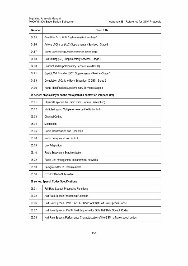
7/30/2019 Signaling Analysis Manual
http://slidepdf.com/reader/full/signaling-analysis-manual 284/290
Signaling Analysis ManualM900/M1800 Base Station Subsystem Appendix E Reference for GSM Protocols
E-8
Number Short Title
04.85 Closed User Group (CUG) Supplementary Services - Stage 3
04.86 Advice of Charge (AoC) Supplementary Services - Stage3
04.87 User-to-User Signalling (UUS) Supplementary Service Stage 3
04.88 Call Barring (CB) Supplementary Services - Stage 3
04.90 Unstructured Supplementary Service Data (USSD)
04.91 Explicit Call Transfer (ECT) Supplementary Service -Stage 3
04.93 Completion of Calls to Busy Subscriber (CCBS); Stage 3
04.96 Name Identification Supplementary Services; Stage 3
05 series: physical layer on the radio path (L1 context on interface Um)
05.01 Physical Layer on the Radio Path (General Description)
05.02 Multiplexing and Multiple Access on the Radio Path
05.03 Channel Coding
05.04 Modulation
05.05 Radio Transmission and Reception
05.08 Radio Subsystem Link Control
05.09 Link Adaptation
05.10 Radio Subsystem Synchronization
05.22 Radio Link management in hierarchical networks
05.50 Background for RF Requirements
05.56 CTS-FP Radio Sub-system
06 series: Speech Codec Specifications
06.01 Full Rate Speech Processing Functions
06.02 Half Rate Speech Processing Functions
06.06 Half Rate Speech - Part 7: ANSI-C Code for GSM Half Rate Speech Codec
06.07 Half Rate Speech - Part 8: Test Sequence for GSM Half Rate Speech Codec
06.08 Half Rate Speech; Performance Characterization of the GSM half rate speech codec
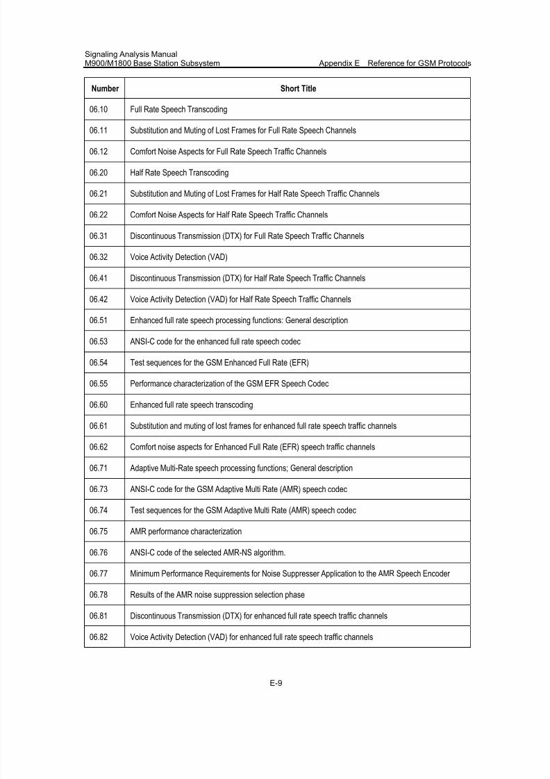
7/30/2019 Signaling Analysis Manual
http://slidepdf.com/reader/full/signaling-analysis-manual 285/290
Signaling Analysis ManualM900/M1800 Base Station Subsystem Appendix E Reference for GSM Protocols
E-9
Number Short Title
06.10 Full Rate Speech Transcoding
06.11 Substitution and Muting of Lost Frames for Full Rate Speech Channels
06.12 Comfort Noise Aspects for Full Rate Speech Traffic Channels
06.20 Half Rate Speech Transcoding
06.21 Substitution and Muting of Lost Frames for Half Rate Speech Traffic Channels
06.22 Comfort Noise Aspects for Half Rate Speech Traffic Channels
06.31 Discontinuous Transmission (DTX) for Full Rate Speech Traffic Channels
06.32 Voice Activity Detection (VAD)
06.41 Discontinuous Transmission (DTX) for Half Rate Speech Traffic Channels
06.42 Voice Activity Detection (VAD) for Half Rate Speech Traffic Channels
06.51 Enhanced full rate speech processing functions: General description
06.53 ANSI-C code for the enhanced full rate speech codec
06.54 Test sequences for the GSM Enhanced Full Rate (EFR)
06.55 Performance characterization of the GSM EFR Speech Codec
06.60 Enhanced full rate speech transcoding
06.61 Substitution and muting of lost frames for enhanced full rate speech traffic channels
06.62 Comfort noise aspects for Enhanced Full Rate (EFR) speech traffic channels
06.71 Adaptive Multi-Rate speech processing functions; General description
06.73 ANSI-C code for the GSM Adaptive Multi Rate (AMR) speech codec
06.74 Test sequences for the GSM Adaptive Multi Rate (AMR) speech codec
06.75 AMR performance characterization
06.76 ANSI-C code of the selected AMR-NS algorithm.
06.77 Minimum Performance Requirements for Noise Suppresser Application to the AMR Speech Encoder
06.78 Results of the AMR noise suppression selection phase
06.81 Discontinuous Transmission (DTX) for enhanced full rate speech traffic channels
06.82 Voice Activity Detection (VAD) for enhanced full rate speech traffic channels
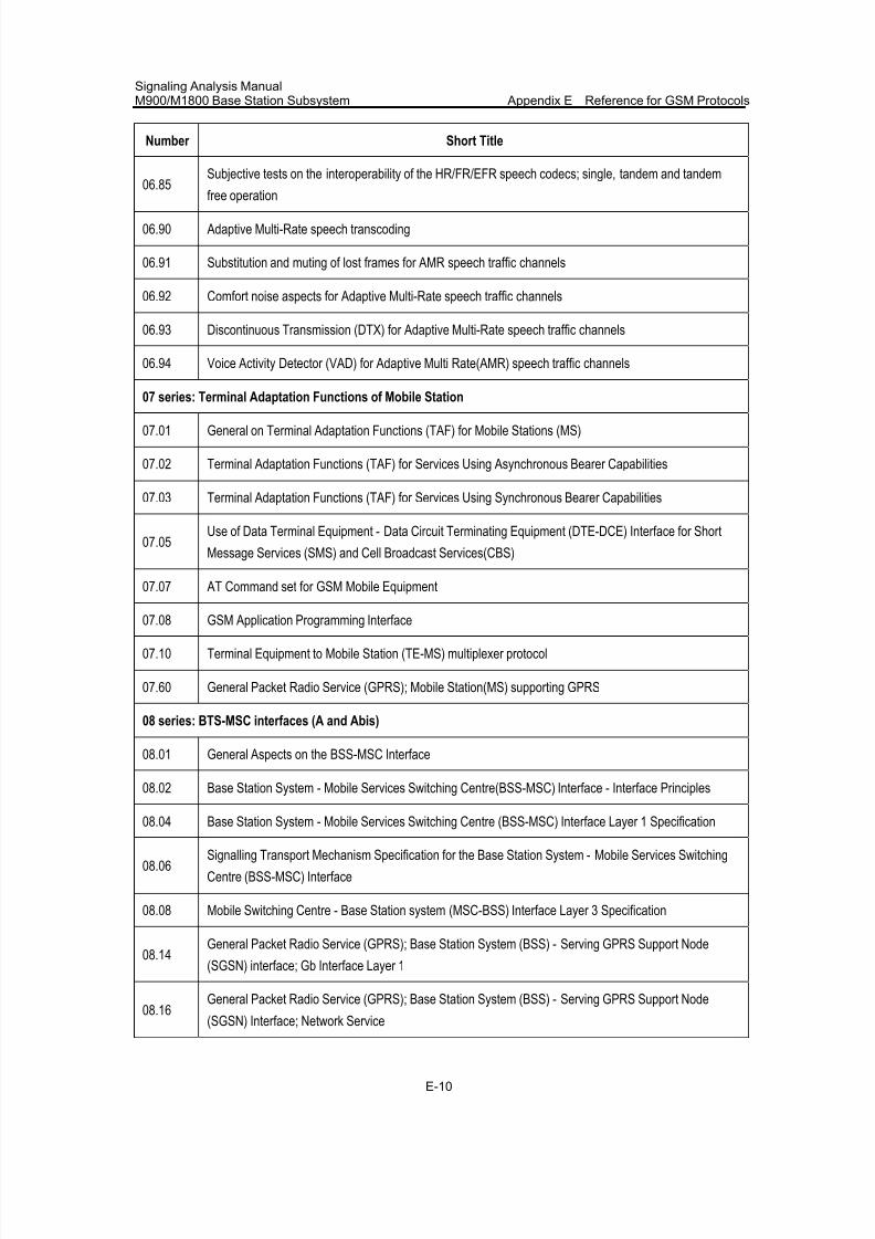
7/30/2019 Signaling Analysis Manual
http://slidepdf.com/reader/full/signaling-analysis-manual 286/290
Signaling Analysis ManualM900/M1800 Base Station Subsystem Appendix E Reference for GSM Protocols
E-10
Number Short Title
06.85Subjective tests on the interoperability of the HR/FR/EFR speech codecs; single, tandem and tandem
free operation
06.90 Adaptive Multi-Rate speech transcoding
06.91 Substitution and muting of lost frames for AMR speech traffic channels
06.92 Comfort noise aspects for Adaptive Multi-Rate speech traffic channels
06.93 Discontinuous Transmission (DTX) for Adaptive Multi-Rate speech traffic channels
06.94 Voice Activity Detector (VAD) for Adaptive Multi Rate(AMR) speech traffic channels
07 series: Terminal Adaptation Functions of Mobile Station
07.01 General on Terminal Adaptation Functions (TAF) for Mobile Stations (MS)
07.02 Terminal Adaptation Functions (TAF) for Services Using Asynchronous Bearer Capabilities
07.03 Terminal Adaptation Functions (TAF) for Services Using Synchronous Bearer Capabilities
07.05Use of Data Terminal Equipment - Data Circuit Terminating Equipment (DTE-DCE) Interface for Short
Message Services (SMS) and Cell Broadcast Services(CBS)
07.07 AT Command set for GSM Mobile Equipment
07.08 GSM Application Programming Interface
07.10 Terminal Equipment to Mobile Station (TE-MS) multiplexer protocol
07.60 General Packet Radio Service (GPRS); Mobile Station(MS) supporting GPRS
08 series: BTS-MSC interfaces (A and Abis)
08.01 General Aspects on the BSS-MSC Interface
08.02 Base Station System - Mobile Services Switching Centre(BSS-MSC) Interface - Interface Principles
08.04 Base Station System - Mobile Services Switching Centre (BSS-MSC) Interface Layer 1 Specification
08.06Signalling Transport Mechanism Specification for the Base Station System - Mobile Services Switching
Centre (BSS-MSC) Interface
08.08 Mobile Switching Centre - Base Station system (MSC-BSS) Interface Layer 3 Specification
08.14General Packet Radio Service (GPRS); Base Station System (BSS) - Serving GPRS Support Node
(SGSN) interface; Gb Interface Layer 1
08.16General Packet Radio Service (GPRS); Base Station System (BSS) - Serving GPRS Support Node
(SGSN) Interface; Network Service
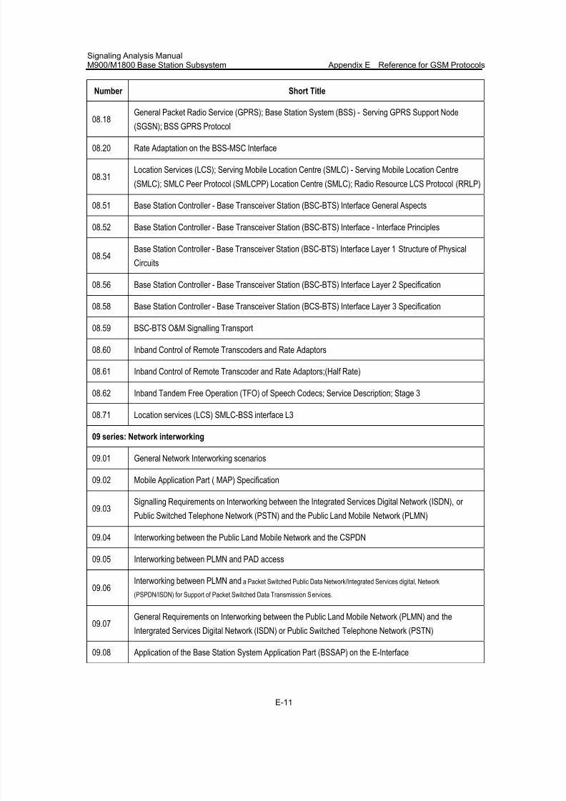
7/30/2019 Signaling Analysis Manual
http://slidepdf.com/reader/full/signaling-analysis-manual 287/290
Signaling Analysis ManualM900/M1800 Base Station Subsystem Appendix E Reference for GSM Protocols
E-11
Number Short Title
08.18General Packet Radio Service (GPRS); Base Station System (BSS) - Serving GPRS Support Node
(SGSN); BSS GPRS Protocol
08.20 Rate Adaptation on the BSS-MSC Interface
08.31Location Services (LCS); Serving Mobile Location Centre (SMLC) - Serving Mobile Location Centre
(SMLC); SMLC Peer Protocol (SMLCPP) Location Centre (SMLC); Radio Resource LCS Protocol (RRLP)
08.51 Base Station Controller - Base Transceiver Station (BSC-BTS) Interface General Aspects
08.52 Base Station Controller - Base Transceiver Station (BSC-BTS) Interface - Interface Principles
08.54Base Station Controller - Base Transceiver Station (BSC-BTS) Interface Layer 1 Structure of Physical
Circuits
08.56 Base Station Controller - Base Transceiver Station (BSC-BTS) Interface Layer 2 Specification
08.58 Base Station Controller - Base Transceiver Station (BCS-BTS) Interface Layer 3 Specification
08.59 BSC-BTS O&M Signalling Transport
08.60 Inband Control of Remote Transcoders and Rate Adaptors
08.61 Inband Control of Remote Transcoder and Rate Adaptors;(Half Rate)
08.62 Inband Tandem Free Operation (TFO) of Speech Codecs; Service Description; Stage 3
08.71 Location services (LCS) SMLC-BSS interface L3
09 series: Network interworking
09.01 General Network Interworking scenarios
09.02 Mobile Application Part ( MAP) Specification
09.03Signalling Requirements on Interworking between the Integrated Services Digital Network (ISDN), or
Public Switched Telephone Network (PSTN) and the Public Land Mobile Network (PLMN)
09.04 Interworking between the Public Land Mobile Network and the CSPDN
09.05 Interworking between PLMN and PAD access
09.06Interworking between PLMN and a Packet Switched Public Data Network/Integrated Services digital, Network
(PSPDN/ISDN) for Support of Packet Switched Data Transmission Services.
09.07General Requirements on Interworking between the Public Land Mobile Network (PLMN) and the
Intergrated Services Digital Network (ISDN) or Public Switched Telephone Network (PSTN)
09.08 Application of the Base Station System Application Part (BSSAP) on the E-Interface
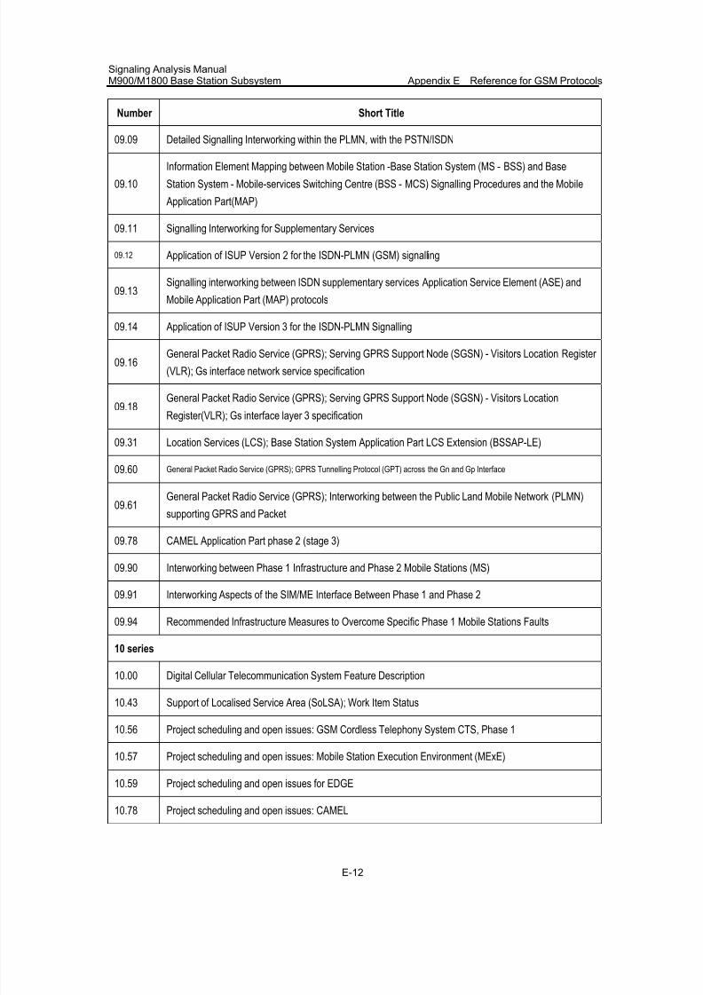
7/30/2019 Signaling Analysis Manual
http://slidepdf.com/reader/full/signaling-analysis-manual 288/290
Signaling Analysis ManualM900/M1800 Base Station Subsystem Appendix E Reference for GSM Protocols
E-12
Number Short Title
09.09 Detailed Signalling Interworking within the PLMN, with the PSTN/ISDN
09.10
Information Element Mapping between Mobile Station -Base Station System (MS - BSS) and Base
Station System - Mobile-services Switching Centre (BSS - MCS) Signalling Procedures and the Mobile
Application Part(MAP)
09.11 Signalling Interworking for Supplementary Services
09.12 Application of ISUP Version 2 for the ISDN-PLMN (GSM) signalling
09.13Signalling interworking between ISDN supplementary services Application Service Element (ASE) and
Mobile Application Part (MAP) protocols
09.14 Application of ISUP Version 3 for the ISDN-PLMN Signalling
09.16General Packet Radio Service (GPRS); Serving GPRS Support Node (SGSN) - Visitors Location Register
(VLR); Gs interface network service specification
09.18General Packet Radio Service (GPRS); Serving GPRS Support Node (SGSN) - Visitors Location
Register(VLR); Gs interface layer 3 specification
09.31 Location Services (LCS); Base Station System Application Part LCS Extension (BSSAP-LE)
09.60 General Packet Radio Service (GPRS); GPRS Tunnelling Protocol (GPT) across the Gn and Gp Interface
09.61 General Packet Radio Service (GPRS); Interworking between the Public Land Mobile Network (PLMN)supporting GPRS and Packet
09.78 CAMEL Application Part phase 2 (stage 3)
09.90 Interworking between Phase 1 Infrastructure and Phase 2 Mobile Stations (MS)
09.91 Interworking Aspects of the SIM/ME Interface Between Phase 1 and Phase 2
09.94 Recommended Infrastructure Measures to Overcome Specific Phase 1 Mobile Stations Faults
10 series
10.00 Digital Cellular Telecommunication System Feature Description
10.43 Support of Localised Service Area (SoLSA); Work Item Status
10.56 Project scheduling and open issues: GSM Cordless Telephony System CTS, Phase 1
10.57 Project scheduling and open issues: Mobile Station Execution Environment (MExE)
10.59 Project scheduling and open issues for EDGE
10.78 Project scheduling and open issues: CAMEL
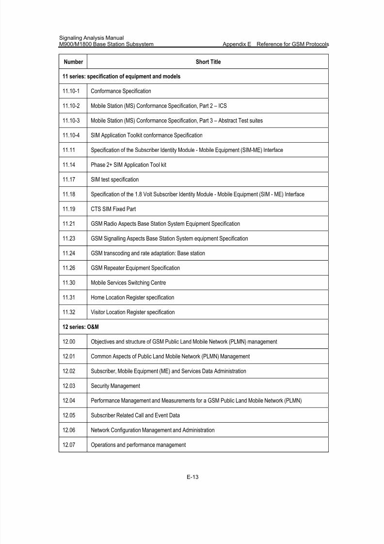
7/30/2019 Signaling Analysis Manual
http://slidepdf.com/reader/full/signaling-analysis-manual 289/290
Signaling Analysis ManualM900/M1800 Base Station Subsystem Appendix E Reference for GSM Protocols
E-13
Number Short Title
11 series: specification of equipment and models
11.10-1 Conformance Specification
11.10-2 Mobile Station (MS) Conformance Specification, Part 2 – ICS
11.10-3 Mobile Station (MS) Conformance Specification, Part 3 – Abstract Test suites
11.10-4 SIM Application Toolkit conformance Specification
11.11 Specification of the Subscriber Identity Module - Mobile Equipment (SIM-ME) Interface
11.14 Phase 2+ SIM Application Tool kit
11.17 SIM test specification
11.18 Specification of the 1.8 Volt Subscriber Identity Module - Mobile Equipment (SIM - ME) Interface
11.19 CTS SIM Fixed Part
11.21 GSM Radio Aspects Base Station System Equipment Specification
11.23 GSM Signalling Aspects Base Station System equipment Specification
11.24 GSM transcoding and rate adaptation: Base station
11.26 GSM Repeater Equipment Specification
11.30 Mobile Services Switching Centre
11.31 Home Location Register specification
11.32 Visitor Location Register specification
12 series: O&M
12.00 Objectives and structure of GSM Public Land Mobile Network (PLMN) management
12.01 Common Aspects of Public Land Mobile Network (PLMN) Management
12.02 Subscriber, Mobile Equipment (ME) and Services Data Administration
12.03 Security Management
12.04 Performance Management and Measurements for a GSM Public Land Mobile Network (PLMN)
12.05 Subscriber Related Call and Event Data
12.06 Network Configuration Management and Administration
12.07 Operations and performance management
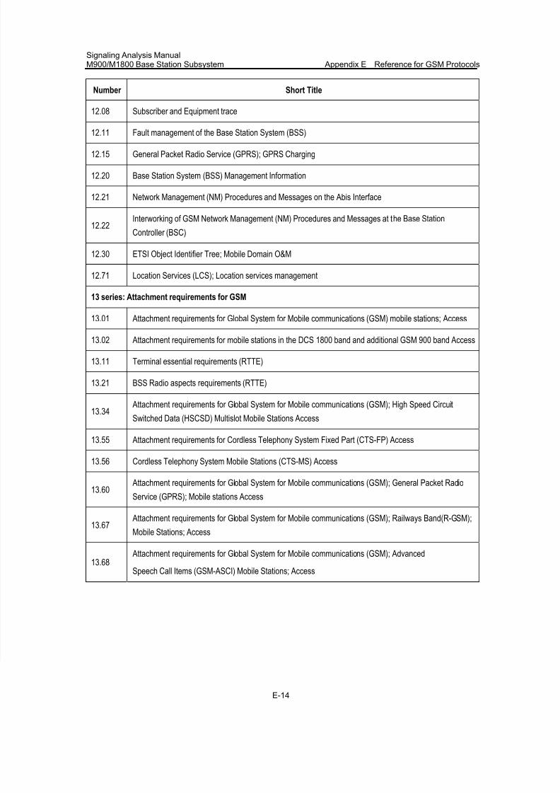
7/30/2019 Signaling Analysis Manual
http://slidepdf.com/reader/full/signaling-analysis-manual 290/290
Signaling Analysis ManualM900/M1800 Base Station Subsystem Appendix E Reference for GSM Protocols


![[Inacon] UMTS Signaling and Protocol Analysis](https://img.pdfslide.net/doc/110x75/563dba6f550346aa9aa5a24f/inacon-umts-signaling-and-protocol-analysis.jpg)
