Embed Size (px)
Citation preview

SIGNING APPLICATIONS 11.3.7
MAY 2012 SARTSM – VOL 2 HEAVY VEHICLES
Fig 11.9 Heavy Vehicle Prohibition at a Freeway Offramp – Ground Mounted
Sign Sequence
6 NO VEHICLES CONVEYING DANGEROUS GOODS

SIGNING APPLICATIONS 11.3.8
SARTSM – VOL 2 TOURISM MAY 2012
Fig 11.10 Heavy Vehicle Prohibition at a Freeway Offramp – Overhead Signs:
Upward Pointing Arrows
6 NO VEHICLES CONVEYING DANGEROUS GOODS
MAY 2012 SARTSM – VOL 2 HEAVY VEHICLES
SIGNING APPLICATIONS 11.3.9
Fig 11.11 Heavy Vehicle Prohibition at a Freeway Offramp – Overhead Signs:
Downward Pointing Arrows
6 NO VEHICLES CONVEYING
DANGEROUS GOODS

SIGNING APPLICATIONS 11.3.10
SARTSM – VOL 2 HEAVY VEHICLES MAY 2012
Fig 11.12 Local Details of Heavy Vehicle Prohibitions

SIGNING APPLICATIONS 11.3.11
MAY 2012 SARTSM – VOL 2 HEAVY VEHICLES
11.3.5 Lane Use Control in Relation to Steep Up-grades
1 Long up-grades tend to slow down vehicles, especially heavy
vehicles, and in order to maintain high levels of service, it is
generally expedient in such areas to separate the slower and
fast moving traffic. An integral part of effectively separating the
slow traffic is achieved through signing.
2 The separation of traffic may be accomplished in one of the
following two ways:
(a) the prohibition of use of certain lanes by heavy vehicles;
(b) the mandatory use of certain lanes by a specific class of
vehicle (which prohibits their use by other classes of vehicle).
3 The signing required is illustrated as follows:
(a) Figure 11.13 indicates the requirements for lane use control
on multilane undivided roads using ground-mounted signs;
(b) Figure 11.14 indicates the requirements for lane use control
on freeways and multilane divided roads using
ground-mounted signs.
(c) Figure 11.15 indicates the requirements for lane use control
on freeways using overhead signs.
4 Command signs incorporated into the diagrammatic sign shall
only be used when the lane so designated is for the
exclusive use of the vehicle type indicated.
5 If the exclusive use of a lane by the class of vehicle to be
controlled is not practical due to the mix of traffic using the road,
effective control may be achieved by specifying an appropriate
MINIMUM SPEED in the right side lane (or centre and right side
lanes on a 3-lane roadway). To achieve such control, command
MINIMUM SPEED sign R101 can be placed in a diagrammatic
sign GS303 or GS305, as appropriate. The value of minimum
speed to be displayed should be determined as a result of an
engineering assessment of the specific site, but it is likely to be
higher than normally used on sign R101, typically in the range of
60 km/h to 80 km/h.
6 Signs are required as follows:
(a) at a minimum distance of 5 km apart where the affected
distance is longer than 5 km; and
(b) in the case of freeways, immediately after every interchange.
7 With regard to construction vehicles, where relevant, temporary
signing may be used during the construction period.
SIGNING APPLICATIONS 11.3.12
SARTSM – VOL 2 HEAVY VEHICLES MAY 2012
Fig 11.13 Lane Use Control on Multi-lane Undivided Roads – Ground Mounted Signs
iv. Vehicles Carrying Dangerous Goods

SIGNING APPLICATIONS 11.3.13
MAY 2012 SARTSM – VOL 2 HEAVY VEHICLES
Fig 11.14 Lane Use Control on Freeways and Divided Multi-lane Roads –
Ground Mounted Signs
iv. Vehicles Carrying Dangerous
Goods

SIGNING APPLICATIONS 11.3.14
SARTSM – VOL 2 HEAVY VEHICLES MAY 2012
Fig 11.15 Lane Use Control on Freeways -
Overhead Signs

SIGNING APPLICATIONS 11.3.15
MAY 2012 SARTSM – VOL 2 HEAVY VEHICLES
11.3.6 Lane and Vehicle Control in Relation to Steep Down-grades
1 A potentially dangerous situation exists for heavy vehicles on
steep and/or long down-grades and effective warning of the
approach of such down-grades in order to slow down the
vehicles timeously to enable the engaging of a low gear is
essential.
2 The following figures illustrate various aspects related to the
signing in advance of a steep down-grade:
(a) Figure 11.16 indicates typical requirements for a two-lane
two-way roadway;
(b) Figure 11.17 indicates typical requirements for a freeway or
multilane divided road;
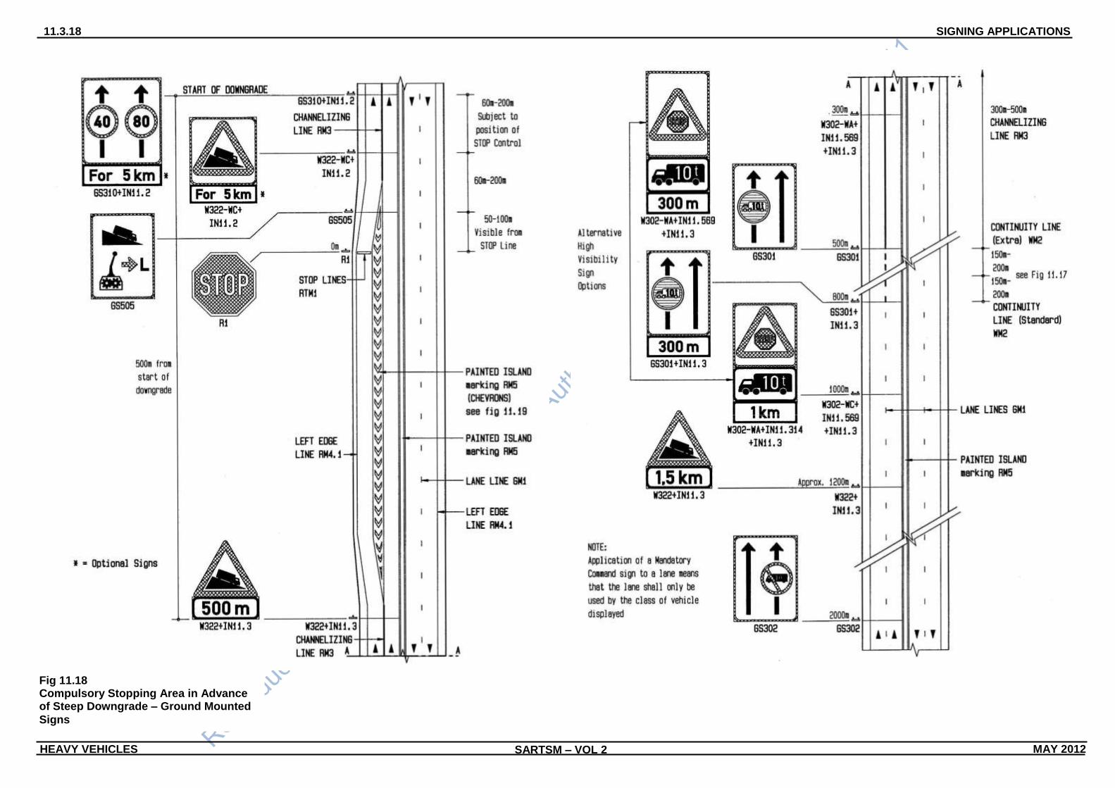
(c) Figure 11.18 indicates typical requirements where there is a
compulsory heavy vehicle stop ahead, in advance of the start
of the down-grade on a freeway or multilane divided road,
using ground-mounted signs;
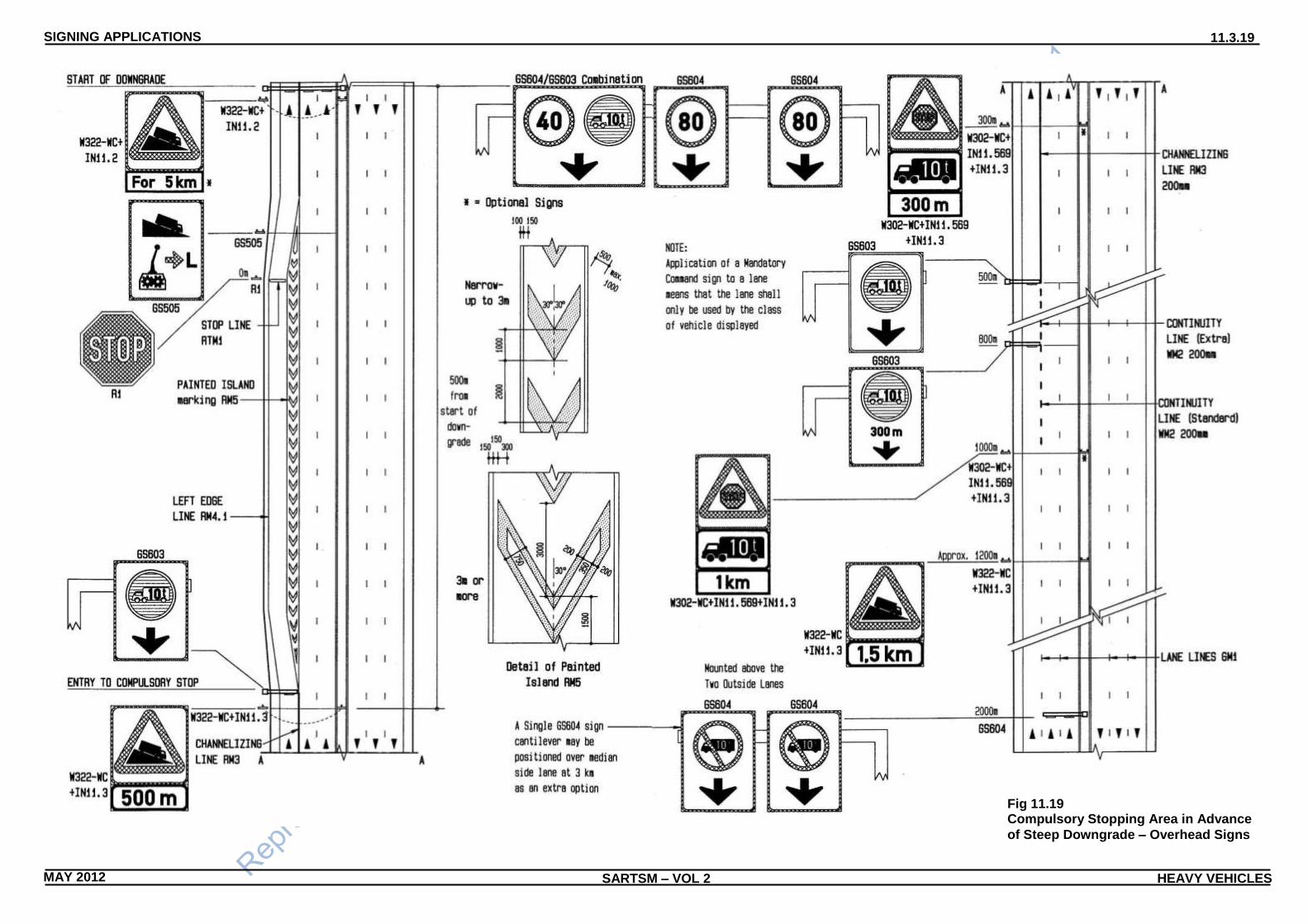
(d) Figure 11.19 indicates typical requirements where there is a
compulsory heavy vehicle stop ahead, in advance of the start
of the down-grade on a freeway or multilane divided road,
using overhead signs.
3 Figure 11.16 illustrates the situation where no special provisions
are made for the heavy vehicles in the way of an exclusive
crawler lane, and thus it is advisable to provide the SLOW
MOVING TRAFFIC advance warning sign W324 at the start of
the down-grade rather than the advance warning of a STEEP
DESCENT sign W322. The maximum speed allowable will be
dictated by the horizontal geometric design of the down-grade.
On long down-grades the W324 and the R201 signs should be
repeated at regular intervals of not more than 2 km.
4 Figure 11.17 illustrates the situation where an exclusive crawler
lane is provided for the heavy vehicles. For a situation where
heavy vehicles are prohibited from the right-hand lane but all
vehicles may use the left-hand lane, then the GS301 or GS303
sign incorporating the R124 sign located at 500 m and 800 m
from the start of the steep descent should be omitted.
5 Figure 11.18 illustrates the situation where a mandatory heavy
vehicle stop is provided in advance of the steep down-grade, and
heavy vehicles are required to use an exclusive crawler lane on
the down-grade. The provision of a stop is desirable in advance
of long and/or steep down-grades and this situation is preferable
to that indicated in Figure 11.17.
6 Figure 11.19 illustrates the situation on a multilane freeway
where a mandatory heavy vehicle stop is provided in advance of
the steep down-grade, and an exclusive crawler lane for heavy
vehicles is provided.

SIGNING APPLICATIONS 11.3.16
SARTSM – VOL 2 HEAVY VEHICLES MAY 2012
Fig 11.16 Steep Downgrades – Two Lane/Two-way Roads

SIGNING APPLICATIONS 11.3.17
MAY 2012 SARTSM – VOL 2 HEAVY VEHICLES
Fig 11.17 Steep Downgrades – Freeway and
Multilane Divided Roads
SIGNING APPLICATIONS 11.3.18
SARTSM – VOL 2 HEAVY VEHICLES MAY 2012
Fig 11.18 Compulsory Stopping Area in Advance of Steep Downgrade – Ground Mounted
Signs
SIGNING APPLICATIONS 11.3.19
MAY 2012 SARTSM – VOL 2 HEAVY VEHICLES
Fig 11.19 Compulsory Stopping Area in Advance
of Steep Downgrade – Overhead Signs

SIGNING APPLICATIONS 11.3.20
SARTSM – VOL 2 HEAVY VEHICLES MAY 2012
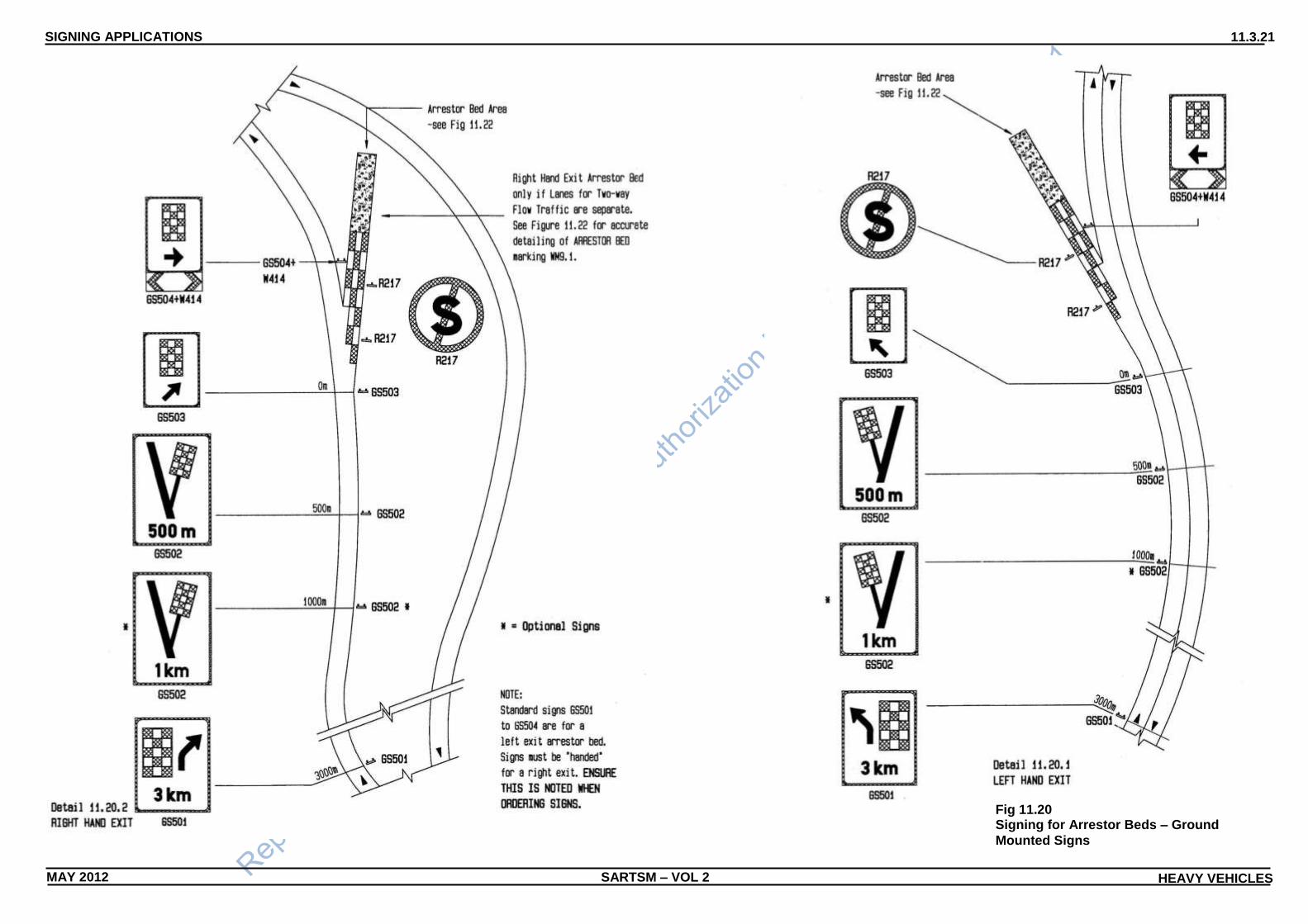
11.3.7 Arrestor Beds/Escape Roads
1 On long and/or steep down-grades, arrestor beds or escape
roads should be provided as a safe escape device for out of
control heavy vehicles. The signing to advise drivers of heavy
vehicles of the approach of an arrestor bed or escape road is as
illustrated in Figure 11.20 and Figure 11.21.
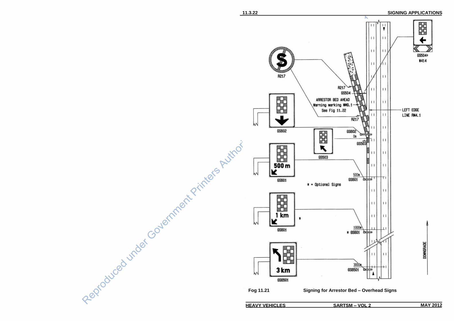
2 Figure 11.20 illustrates the signing requirements on an arrestor
bed approach using ground-mounted signs while Figure 11.21
illustrates the signing requirements on the approach to an
arrestor bed on a freeway using overhead signs. Similar signing
may be used on the approach to an escape road (see paragraph
11.3.7.5).
3 On two-way single lane roads the arrestor bed should have a
left-hand exit unless the lanes are split as indicated in Figure
11.20.
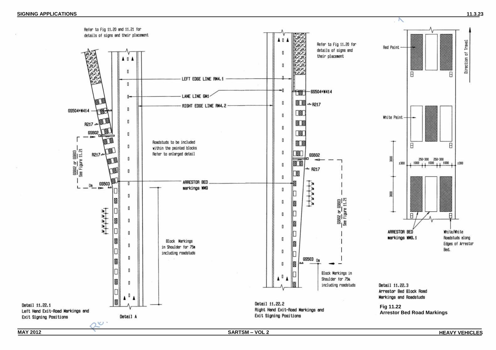
4 Figure 11.22 illustrates the special markings required at an
arrestor bed. In addition to the paint markings, white roadstuds
are to be placed along the outside edge of the arrestor bed
apron for clear demarcation of the arrestor bed at night or in
misty weather.
5 Figure 11.23 shows the special markings required when an
escape road is provided. The function of an escape road is to
provide an unobstructed path through what would otherwise be a
physical barrier across a roadway, on, or at the end of, a long
and/or steep downgrade. The most likely application is at a toll
plaza spanning the full width of the plaza apron. The route of the
escape road, and its position through the plaza should be as
direct as possible so that a heavy vehicle driver is not required to
significantly change direction of a runaway vehicle on the
approach to the plaza. The purpose of road marking WM9.2 is to
make this direct path obvious.
6 Subject to expected weather conditions at an arrestor bed i.e.
mist or fog, the reduced area of coverage of marking WM9.2
may be considered at arrestor beds.
7 Due to the relatively small size of ARRESTOR BED symbol
GSS1 on signs GS501 to GS504 it is recommended that the
same symbol be used for signs provided for both arrestor beds
and escape routes.
SIGNING APPLICATIONS 11.3.21
SARTSM – VOL 2 HEAVY VEHICLES MAY 2012
Fig 11.20 Signing for Arrestor Beds – Ground
Mounted Signs
SIGNING APPLICATIONS 11.3.22
SARTSM – VOL 2 HEAVY VEHICLES MAY 2012
Fog 11.21 Signing for Arrestor Bed – Overhead Signs
SIGNING APPLICATIONS 11.3.23
SARTSM – VOL 2 HEAVY VEHICLES MAY 2012
Fig 11.22
Arrestor Bed Road Markings

SIGNING APPLICATIONS 11.3.24
SARTSM – VOL 2 HEAVY VEHICLES MAY 2012
Fig 11.23
Escape Road Markings

SIGNING APPLICATIONS 11.3.25
SARTSM – VOL 2 HEAVY VEHICLES MAY 2012
11.3.8 Compulsory Use of a Mass Measuring Station
1 The approach to a mass measuring station should be signed as
illustrated in Figure 11.24. If the mass measuring station is not
permanently manned, allowance should be made for signs to be
covered up or removed when the mass measuring station is not
operational.
2 On single lane two-way traffic roads carrying heavy volumes of
traffic an additional deceleration lane, at least 300 metres long,
should be provided on the approach to the mass measuring
station entrance for the heavy vehicles (see Detail 11.24.2).

SARTSM – VOL 2 HEAVY VEHICLES MAY 2012
SIGNING APPLICATIONS 11.3.26
Fig 11.24
Mass Measuring Station
SIGNING APPLICATIONS 11.3.27
SARTSM – VOL 2 HEAVY VEHICLES MAY 2012
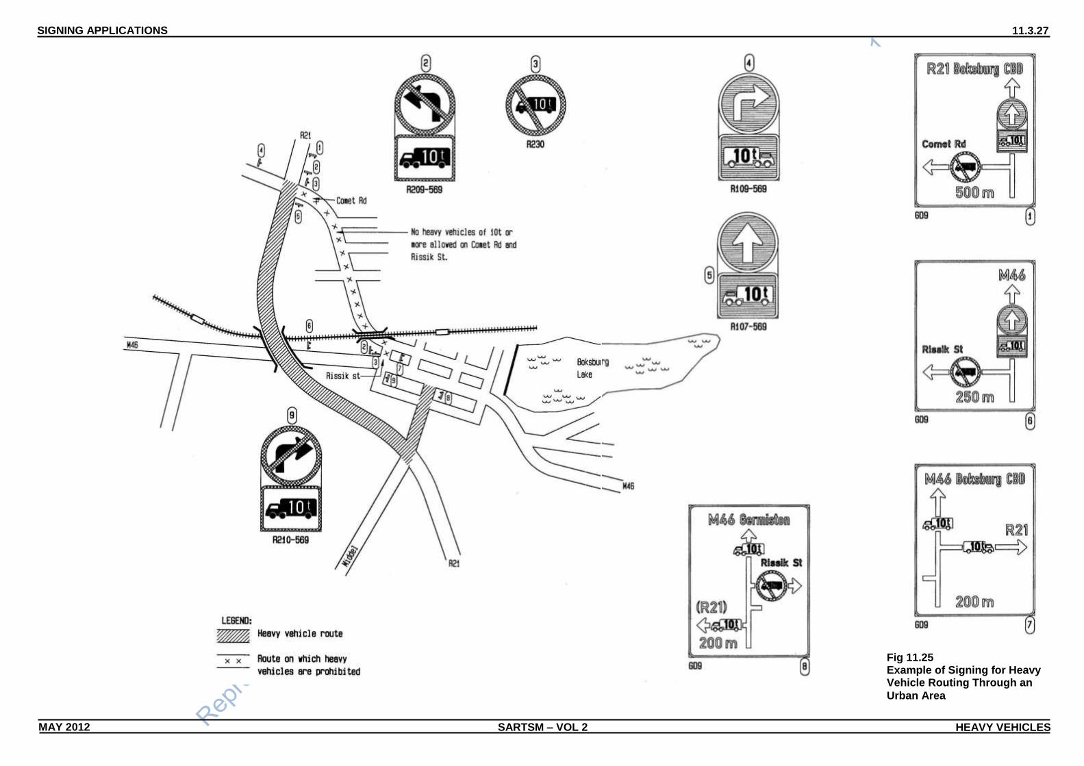
Fig 11.25 Example of Signing for Heavy Vehicle Routing Through an
Urban Area

SOUTHERN
AFRICAN
DEVELOPMENT
COMMUNITY
SARTSM – VOL 2
WARNING SIGNS
JUNE 2012
SECTIONS
3.0 Contents
3.1 Introduction
3.2 Road Layout Signs
3.3 Direction of Movement Signs
3.4 Symbolic Signs
3.5 Hazard Marker Signs
3.6 Warning Sign Combinations
3.7 National Variants
SIGNING FOR TRAFFIC CALMING
MAY 2012
SECTIONS
12.0 Contents
12.1 Introduction
12.2 Types of Traffic Calming Measures
12.3 Planning for Traffic Calming
12.4 Traffic Calming Signing Applications
CHAPTER 12

TITLE
SOUTH AFRICAN ROAD TRAFFIC SIGNS MANUAL Volume 2 Chapter 12
ISBN STATUS DOT FILE DATE
Digitised Version 000/0/0/0 Digitised May 2012
DIGITISING CARRIED OUT BY
Transport and Traffic Technology Africa (Pty) Ltd P O Box 1109 SUNNINGHILL 2157
COMMISSIONED BY
Department of Transport
Private Bag X193
PRETORIA
0001
ORIGINAL AUTHOR PUBLISHER ENQUIRIES
W Kennedy Director-General: Transport Private Bag X193 PRETORIA 0001
It is impossible for a publication of this nature to free of errors. It would be appreciated if errors be brought to the notice of -
Director-General: Transport
Department of Transport
Infrastructure Network Management
Private Bag X193
PRETORIA
0001
COPYRIGHT
This publication is protected by copyright under the Bern Convention. In terms of the Copyright Act No. 98 of 1978, no part of this publication may be produced or transmitted in any form or by any means, electronic or mechanical, including photocopying, recording or by any information storage or retrieval system, without permission in writing from the publisher. © National Department of Transport 1999, 2012
KEYWORDS
ROAD SIGN, ROAD MARKING, REGULATORY, WARNING
COST: VOLUME 2
VOLUME SET R
Chapter 1 R Chapter 11 R Chapter 2 R Chapter 12 R Chapter 3 R Chapter 13 R Chapter 4 R Chapter 14 R Chapter 5 R Chapter 15 R Chapter 6 R Chapter 16 R Chapter 7 R Chapter 17 R Chapter 8 R Chapter 18 R Chapter 9 R Chapter 19 R Chapter 10 R


CONTENTS 12.0.1
MAY 2012 SARTSM – VOL 2 TRAFFIC CALMING
CHAPTER 12: SIGNING FOR TRAFFIC CALMING
CONTENTS
12.0.1 Sections and Subsections
Number Title Page No.
12.0 CONTENTS 12.0.1
12.0.1 Sections and Subsections 12.0.1
12.0.2 Figures 12.0.1
12.1 INTRODUCTION 12.1.1
12.1.1 General 12.1.1
12.1.2 Road Traffic Sign Colour Code Indicators 12.1.4
12.2 TYPES OF TRAFFIC CALMING MEASURES 12.2.1 12.2.1 General 12.2.1 12.2.2 Mini-circles 12.2.1 12.2.3 Raised Intersections 12.2.1 12.2.4 Intersection Diverters 12.2.1 12.2.5 Street Closures 12.2.4 12.2.6 Intersection Narrowing 12.2.4 12.2.7 Speed Humps 12.2.4 12.2.8 Chicane – Pinch Points/Chokers 12.2.4 12.2.9 Rumble Strips 12.2.4 12.2.10 Carriageway narrowing 12.2.4 12.2.11 Pedestrian Crossing/Table 12.2.4 12.2.12 Semi-spheres 12.2.4 12.2.13 The “Woonerf” 12.2.5 12.2.14 Area-wide Measures 12.2.5
12.3 PLANNING FOR TRAFFIC CALMING 12.3.1 12.3.1 Traffic Calming Objectives and Planning Overview 12.3.1
12.3.2 Traffic Calming Study Requirements 12.3.1
12.3.3 Public Involvement 12.3.1
12.3.4 Study Area Definition 12.3.2
12.3.5 Survey Requirements 12.3.2
12.3.6 Study Requirements 12.3.2
12.4 TRAFFIC CALMING SIGN APPLICATIONS 12.4.1 12.4.1 General 12.4.1 12.4.2 Mini-circles 12.4.2 12.4.3 Notes on Figure 12.6 12.4.3 12.4.4 Speed Humps 12.4.4 12.4.5 Notes on Figure 12.7 12.4.5 12.4.6 Chicanes or Pinch Points 12.4.6 12.4.7 Notes on Figure 12.8 12.4.7 12.4.8 Raised Junctions 12.4.8 12.4.9 Notes on Figure 12.9 12.4.9
12.0.2 Figures Figure No. Title Page No. Fig 12.1 Signs and Markings Used for Traffic calming Measures - 1 12.1.2 Fig 12.2 Signs and Markings Used for Traffic calming Measures - 2 12.1.3 Fig 12.3 Traffic Calming Measures Used at Intersections 12.2.2 Fig 12.4 Traffic Calming Measures Used Between Intersections 12.2.3 Fig 12.5 Typical Environment Approach to Traffic Calming 12.2.3

SARTSM – VOL 2 TRAFFIC CALMING MAY 2012
CONTENTS 12.0.2
Figure No. Title Page No. Fig 12.6 Typical Road Sign Layout for Mini-Circles 12.4.3 Fig 12.7 Typical Road Sign Layout for Speed Humps 12.4.5 Fig 12.8 Typical Road Sign Layout for Chicanes/Pinch Points 12.4.7 Fig 12.9 Typical Road Sign Layout for Raised Intersections 12.4.9

INTRODUCTION 12.1.1
MAY 2012 SARTSM – VOL 2 TRAFFIC CALMING
CHAPTER 12: SIGNING FOR TRAFFIC CALMING
12.1 INTRODUCTION
12.1.1 General
1 The objective of traffic calming is to improve traffic safety and the
living environment by moderating traffic behaviour through physical
and legislative measures aimed at reducing vehicle speeds and/or
traffic volumes whilst giving due regard to mobility and accessibility
requirements.
2 The objective of this chapter is to provide guidance regarding the
application of road traffic signs for Traffic Calming Measures. In this
context this guidance consists of providing information on the road
signs and markings to be used when implementing traffic calming
measures and providing examples of road signing and road
marking layouts.
3 Prior to formulating any decision on the implementation of traffic
calming measures, it is important to be aware of the large number
of traffic calming measures that do exist and which can be
incorporated into a traffic calming concept. A section of this chapter
is therefore devoted to defining different types of traffic calming
measures.
4 Since the concept of traffic calming is relatively new to South Africa,
viewpoints on the merits of traffic calming can vary substantially.
This Chapter should not be seen as a guideline for or against
the implementation of traffic calming measures per se.
However, the Chapter does address the issue of planning for traffic
calming. This is deemed necessary because, although committees
have been established with the objective of developing "Traffic
Calming Guidelines", there are presently no generally accepted
policies at a national, regional or local authority level nor has it yet
been ascertained whether this need exists at all three levels. At this
point in time it should therefore, be recognised that the
implementation of traffic calming measures should not be brought
about by, for example, an automatic and instantaneous decision by
a road authority. On the contrary, it should be acknowledged that
the traffic calming concept is a very complex one and that the
implementation of traffic calming can have far reaching implications.
Hence there is a vital need to ensure that appropriate and
extensive study work has been undertaken, and is available prior to
the decision making process, and it is therefore the required
elements of this study work that are addressed herein.
5 Since it was only in the last quarter of 1993 that certain signs and
markings relevant to traffic calming measures were prescribed in
the Road Traffic Act, Volumes 1 and 4 of the South African Road
Traffic Signs Manual only address the concept in a limited manner
(refer to paragraph 12.1.1.6). Nevertheless, in regard to road traffic
sign design, and by way of general comment, it can be stated that
the signs required in terms of implementing traffic calming
measures generally fall into the regulatory, warning and information
classifications, and examples of such signs are provided herein. In
addition, and since the objective of traffic calming is to "calm" traffic
which in turn can infer a lowering of vehicle speed, the size of such
signs is usually governed by the dimensions provided in Volume 4
for a speed limit of less than or equal to 60 km/h. Since the number
of signs prescribed in the Manual which directly relate to traffic
calming measures are limited, there are many other regulatory,
warning and information signs which can be used in conjunction
with the provision of traffic calming measures (see Figures 12.1 and
12.2). Nevertheless, as more measures come to the fore, and the
need to implement these measures gains general approval, there
may well be the need to prescribe additional traffic calming signs
both in the Road Traffic Act, and in the South African Road Traffic
Signs Manual.
6 Relevant references in Volume 1, which will not be repeated in this
chapter, are as follows:
(a) requirements of traffic control devices (Subsection 1.1.5);
(b) uniformity of traffic control devices (Subsection 1.1.6);
(c) placement of traffic control devices (Subsection 1.1.7);
(d) principles of signing (Subsection 1.1.9);
(e) environmental impact (Subsection 1.1.20);
(f) legal aspects (Subsection 1.1.22);
(g) road traffic sign classification (Section 1.3);
(h) shape, size and colour (Section 1.4);
(i) sign placement (Section 1.6);
(j) all of Chapter 2: Regulatory Signs, but specifically:
(i) Section 2.1 Introduction;
(ii) Section 2.2 Control signs;
(iii) Section 2.3 Command signs;
(iv) Section 2.4 Prohibition signs;
(v) Subsection 2.6.3 Woonerf;
(k) all of Chapter 3: Warning Signs, but specifically:
(i) Section 3.1 Introduction;
(ii) Section 3.3 Direction of Movement signs;
(iii) Section 3.4 Symbolic signs;
(iv) Section 3.5 Hazard Marker signs;
(v) Section 3.6 Combinations;
(l) all of Chapter 5: Information Signs, but specifically:
(i) Section 5.1 Introduction;
(ii) Subsection 5.2.2 Cul-de-sac;
(iii) Subsection 5.2.5 Supplementary Plates;

12.1.2 INTRODUCTION
SARTSM – VOL 2 TRAFFIC CALMING MAY 2012
Fig 12.1 Signs and Markings Used for Traffic Calming Measures - 1

INTRODUCTION 12.1.3
SARTSM – VOL 2 TRAFFIC CALMING MAY 2012
Fig 12.2 Signs and Markings Used for Traffic Calming Measures - 2

SARTSM – VOL 2 TRAFFIC CALMING MAY 2012
12.1.4 INTRODUCTION
(m) all of Chapter 7: Road Markings, but specifically:
(i) Section 7.1 Introduction;
(ii) Section 7.2 Regulatory markings;
(iii) Section 7.3 Warning markings;
(iv) Section 7.4 Guidance markings
(v) Section 7.5 Roadstuds.
7 The following references to relevant parts of Volume 4 will also not
be repeated elsewhere in this chapter:
(a) road traffic sign sizes (Section 1.2);
(b) dimensional details (Section 1.3);
(c) arrows and letters on road signs (Section 1.4);
(d) all of Chapter 2: Regulatory Signs but specifically:
(i) Section 2.1 Introduction;
(ii) Section 2.2 Control signs;
(iii) Section 2.3 Command signs;
(iv) Section 2.4 Prohibition signs;
(v) Subsection 2.6.3 Woonerf;
(e) all of Chapter 3: Warning Signs but specifically:
(i) Section 3.1 Introduction;
(ii) Section 3.3 Direction of Movement signs;
(iii) Section 3.4 Symbolic signs;
(iv) Section 3.5 Hazard Marker signs;
(f) all of Chapter 9: Information Signs but specifically:
(i) Section 9.1 Introduction;
(ii) Section 9.2, pages 9.2.2 to 9.2.5, Cul-de-sac;
(iii) Section 9.2, pages 9.2.8 to 9.2.13, Supplementary Plates;
(iv) Section 9.3 Symbols;
(g) all of Chapter 11: Lettering for Road Traffic Signs;
(h) all of Chapter 12: Road Markings.
12.1.2 Road Traffic Sign Colour Indication
1 The chapters of Volume 2 of the South African Road Traffic
Signs Manual (SARTSM) are not prepared in colour.
Re levant examples used to i l l us t rate appropr ia te
s igns , s igna ls and mark ings are shaded in a
b lack and wh i te cod ing wh ich is i l l us t rated
be low.
2 The basic principles of the road traffic sign colour coding
system are shown, in colour, in the SADC-RTSM Volume 1,
Chapter 1, Section 1.4, and in the Contents sections of
relevant Volume 1 and 4 Chapters.

TRAFFIC CALMING MEASURES 12.2.1
MAY 2012 SARTSM – VOL 2 TRAFFIC CALMING
12.2 TYPES OF TRAFFIC CALMING MEASURES
12.2.1 General
1 Different types of traffic calming measures are categorised
below in terms of those measures normally located at
intersections, those located between intersections, and
area-wide measures.
2 The measures are described in terms of their traffic calming
objective, however, this is not to say that the use of such
measures is restricted solely to traffic calming schemes. On the
contrary, several of these measures are, under appropriate
circumstances, excellent traffic control devices. Examples in
this regard would be the use of mini-circles as a traffic
management/control device at intersections, or the use of
rumble strips not to calm urban traffic but to warn traffic, say on
a rural road, to reduce speed because of a sharp curve ahead.
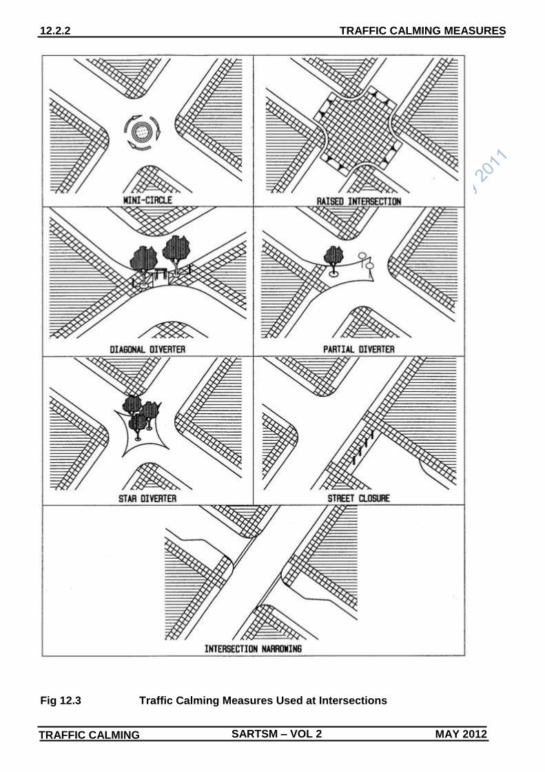
3 The descriptions of the traffic calming measures given in
Subsections 12.2.2 to 12.2.14 should be read in conjunction
with the individual sketches given in Figures 12.3 and 12.4.
4 The different types of traffic calming measures can be broadly
classified in terms of where they are used within the road
network as follows:
(a) measures used at intersections (see Subsections 12.2.2 to
12.2.6);
(b) measures used between intersections (see Subsections
12.2.7 to 12.2.12); and
(c) area wide measures (see Subsections 12.2.13 and
12.2.14).
5 Traffic calming measures applied at intersections are primarily
aimed at reducing speed into the road or limiting or removing
access movements. The more common traffic calming
measures applied at intersections are:
(a) mini-circles;
(b) raised intersections;
(c) intersection diverters;
(d) street closures;
(e) intersection narrowing.
6 The main objective of traffic calming measures applied
between intersections is to reduce vehicle speeds. These
measures may be used in conjunction with landscaping, using
physical elements such as trees, posts or bollards to
emphasise the site and to improve the street environment.
Traffic calming measures commonly applied between
intersections include:
(a) speed humps;
(b) chicanes, pinch points or chokers;
(c) rumble strips;
(d) carriageway narrowing;
(e) pedestrian crossing/table;
(f) semi-spheres.
7 Area-wide measures include the following holistic applications
of traffic calming:
(a) "Woonerf";
(b) more traditional general treatments such as one-way
systems.
12.2.2 Mini-circles
1 Mini-circles have evolved from the conventional traffic circle
(i.e. a traffic circle normally with a large physical inner island)
with the objective of endeavouring to develop a traffic control
device which will induce correct usage, and which is inherently
self-regulating, and which can also be used as a traffic calming
measure. They are widely used to reduce vehicle speed and to
minimise vehicle stops at intersections. Their major advantage
is that they do not stop traffic to the same extent as traffic
signals and STOP signs. For mini-circles, raised central islands
are a better option than painted central islands as the latter are
unsightly and are not as effective in reducing the speed of
motor vehicles.
2 The use of mini-circles, has, to some extent, led to confusion
amongst motorists regarding the correct behaviour at a
mini-circle. For this reason guidelines for motorists to follow
when approaching a mini-circle, are included in Subsection
12.4.2 (see also Chapters 2 and 3 on general elements of
junction control).
12.2.3 Raised Intersections
1 Raised intersections are design features intended to make
drivers aware of the presence of a junction. In residential areas
greater pedestrian movements can be expected at junction,
and the raised junction area therefore introduces a greater
pedestrian safety element. Because it is raised, normally to a
height of 50 mm to 100 mm above normal road surface, it is
more visible and it thus produces a reduction in speed. It is also
a useful measure to use on the perimeter of the traffic calming
area as a means of informing the motorist that such an area is
being approached.
2 A potential problem with raised intersections is that they can
interfere with the traffic flow priorities at intersections. At a
major/minor road intersection, for example, the traffic on the
major road will slow down as it approaches the raised
intersection (either because of its raised nature or because of
pedestrians crossing the road), and this can often be viewed by
the traffic on the minor road, which under normal circumstances
would be under stop or yield control, as an opportunity to
proceed either across the intersection or into the main road.
This tendency for raised intersections to equalise priority can,
to a large degree, be overcome by appropriate signing.
Nevertheless, prior to introducing this type of traffic calming
measure, it should be ensured that the benefits of the measure,
in traffic calming terms, outweigh any dis-benefits resulting from
poorer traffic control/management, and a mix-up of traffic flow
priorities.
12.2.4 Intersection Diverters
1 There are three primary types of diverters which are, the
diagonal, partial and star diverters. Their main objective is to
make the trip length through the local residential area longer by
creating a "maze" type of system. They can be used in isolation
12.2.2 TRAFFIC CALMING MEASURES
SARTSM – VOL 2 TRAFFIC CALMING MAY 2012
Fig 12.3 Traffic Calming Measures Used at Intersections

SARTSM – VOL 2 TRAFFIC CALMING MAY 2012
TRAFFIC CALMING MEASURES 12.2.3
Fig 12.4 Traffic Calming Measures Used Between Intersections

SARTSM – VOL 2 TRAFFIC CALMING MAY 2012
12.2.4 TRAFFIC CALMING MEASURES
with no other supplementary traffic measures, and are very
effective.
2 They do, however, create access restrictions for the local
residents and emergency vehicles. The diagonal diverter is a
barrier placed diagonally across a four-leg intersection which
converts the roadway into separate streets and prevents
through traffic movements at the intersection. The semi-diverter
is a barrier placed diagonally across a four-leg intersection
which limits some but not all movements at the intersection.
The star-diverter basically consists of a central star-shaped
island which only allows left turning movements at the
intersection (see Figure 12.3).
12.2.5 Street Closures
1 Street closures completely remove all vehicular traffic from the
road, and can be accomplished by creating a cul-de-sac at a
junction. However, street closures cannot be introduced until
alternative routes for the displaced traffic have been identified.
2 In addition, any decision to close a street as a traffic calming
measure, should include in the assessment process, planning
for the ultimate visual closure of the road by means of
landscaping measures. Due consideration must be given also
to the likely need for vehicles to turn around in the cul-de-sac.
12.2.6 Intersection Narrowing
1 Intersection narrowing a measure to restrict access and can be
designed to operate either as a one-way or two-way access
system. When used as a two-way access system it essentially
acts as a "pinch point" (see Subsection 12.3.2) located at an
intersection.
12.2.7 Speed Humps
1 Speed humps are an extremely effective means of reducing
vehicle speeds. Speed humps are most suitable for local
collectors and access roads, and overseas experience shows
that they are most commonly used in residential streets with
traffic flows of up to 500 vehicles/hour. Both round and flat top
(raised plateau) speed humps are acceptable. A major
advantage of flat topped road humps is that they can be used
as pedestrian crossings. Speed humps must be located along a
road such that they are always preceded by a speed reducing
feature, such as another speed hump (in a series), and by road
markings. A hump may be of any height between 50 mm and
100 mm to suit particular cases. The length of the hump is
greater than that of a motor vehicle's wheelbase, yet it
constrains the speed of cars. It is acceptable to use a variety of
heights and profiles in a series of speed humps but the length,
(the dimension parallel to the road centreline) should be in the
order of 3,5 m to 4,0 m.
2 The use of speed bumps (i.e. humps of minimal length) is
not supported since they can, if not seen by oncoming
drivers, result in drivers losing control of their vehicles.
There is no restriction on the number of humps in a series but it
is recommended that not more than 20 be used.
12.2.8 Chicane - Pinch Points/Chokers
1 A chicane is formed by developing two adjacently located pinch
points/chokers on opposite sides of the road. These measures
reduce the carriageway width at either one location, or two
adjacent locations on opposite sides of the road. The width
reduction can vary to allow two cars to pass each other slowly,
but where it would be difficult for a car and a bus or heavy
vehicle to pass "comfortably". The most common form allows
for the passage of one vehicle, in one direction only, at a time.
2.2.9 Rumble Strips
1 Rumble Strips are rough surface areas or transverse strips
commonly provided in sets, at progressively decreasing
spacings between sets. Rumble strips introduce a type of noise
and vibration that contrasts with an asphalt, concrete or paved
surface, and therefore give a clear indication to drivers that they
should reduce their speed. It is generally accepted that rumble
strips can be a useful speed reducing instrument, but in
residential areas their usefulness is limited as a result of the
noise and vibration effects. For this reason their use in urban
areas is, in general, not recommended.
12.2.10 Carriageway Narrowing
1 Carriageway narrowing has been widely used in town centres
and residential areas. It is used over the total section of road
that requires traffic calming. It can be accomplished in a
number of ways, which include planting trees/widening the
pavement; providing a central reservation; providing
multi-purpose side strips/providing bus lanes and providing
cycle lanes. Whilst planting trees on the side of the carriageway
can be a cheap option, it can cause problems with underground
utility services. In isolation the use of hatched areas has almost
no influence on vehicle speeds but does seem more effective
when combined with other measures. The provision of bus
lanes and cycle lanes reduces road capacity, but has a minimal
effect on motor vehicle speed.
12.2.11 Pedestrian Crossing/Table
1 Pedestrian crossings/tables basically consist of a wide speed
hump (see Subsection 12.2.7) with a flattened mid-section to
facilitate a pedestrian crossing. They are typically used where
motorists need to be made aware of the presence of
pedestrians. They can be used on access roads to schools,
hospitals, pedestrian malls, etc.
12.2.12 Semi-spheres
1 Semi-spheres are designed to have the same effect as speed
humps, namely to reduce vehicle speeds. They can be made
from a variety of materials but one of the most common form
consists of individual compressible plastic spheres aligned in
two or three rows across the road. Since it is generally only
possible to travel over the spheres at very low speeds and
since they can constitute a danger to traffic, especially
motorcycles, they should only be used downstream of another
speed reducing measure or where vehicles speeds are very
low (5 km/h to 10 km/h). For this reason their use on public
streets is generally not favoured, although where the intention
is to keep all vehicle speeds low (e.g. in car parks and/or on
circulatory roads to and from car parks), they can be effective.
12.2.13 The "Woonerf"
1 "Woonerf", meaning "shared space", is a concept rather than a
specific traffic calming measure. The primary aim of the
woonerf concept is to create an environment in which human
activities have priority. Features inherent in the woonerf
concept and/or area, may include the discouragement of traffic
by formulating designs which only permit low vehicle speeds,
reducing vehicle speeds by signing or specific traffic calming


12.2.5 TRAFFIC CALMING MEASURES
SARTSM – VOL 2 TRAFFIC CALMING MAY 2012
measures, utilizing hard and soft landscaping, different surface
treatments and street furniture, and even laying down codes of
driver behaviour to be adhered to when travelling within the
woonerf.
12.2.14 Area-wide Measures
1 These include one-way street systems, maze or limited entry
systems. The systems are applied where access and/or egress
is to be limited either totally (no-entry or no-exit), or partially
(turn prohibitions, time restrictions etc.). The systems are
applied to eliminate through traffic movements and to reduce
vehicle speeds.


PLANNING 12.3.1
MAY 2012 SARTSM – VOL 2 TRAFFIC CALMING
12.3 PLANNING FOR TRAFFIC CALMING
12.3.1 Traffic Calming Objectives and Planning Overview
1 The principle goal of traffic calming is to improve or reinstate
the social and environmental attributes of residential
neighbourhoods. In terms of this goal, and as defined in
overseas literature, the principle objective should not be to
exclude traffic, but rather to manage and moderate its
behaviour, whereby accessibility and mobility for residents,
shoppers, workers or visitors is not significantly reduced.
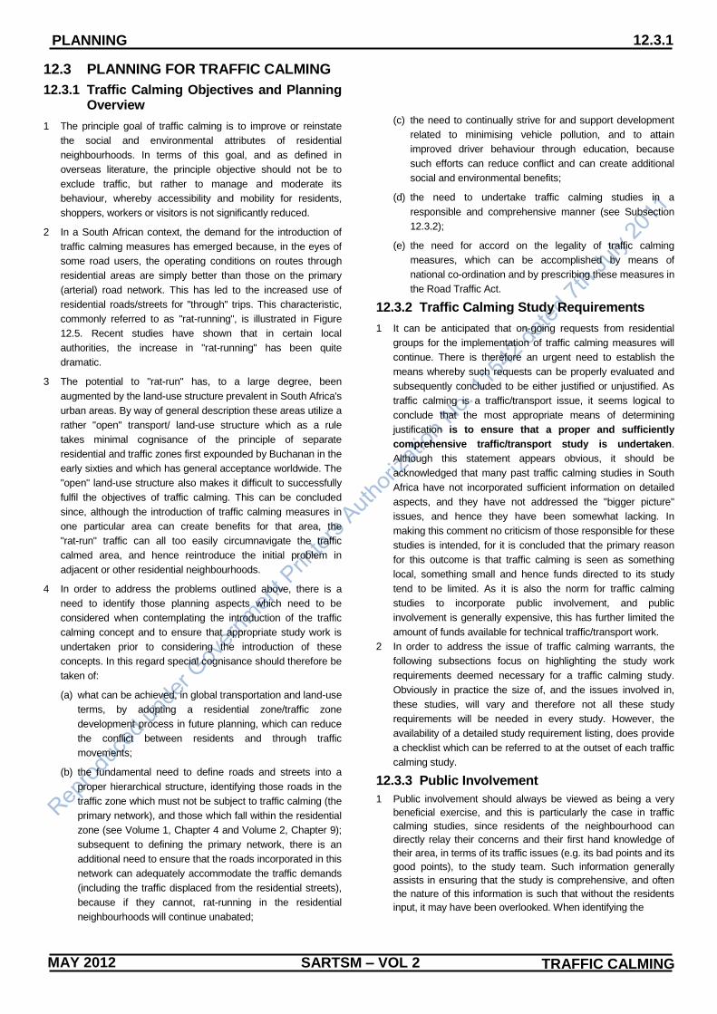
2 In a South African context, the demand for the introduction of
traffic calming measures has emerged because, in the eyes of
some road users, the operating conditions on routes through
residential areas are simply better than those on the primary
(arterial) road network. This has led to the increased use of
residential roads/streets for "through" trips. This characteristic,
commonly referred to as "rat-running", is illustrated in Figure
12.5. Recent studies have shown that in certain local
authorities, the increase in "rat-running" has been quite
dramatic.
3 The potential to "rat-run" has, to a large degree, been
augmented by the land-use structure prevalent in South Africa's
urban areas. By way of general description these areas utilize a
rather "open" transport/ land-use structure which as a rule
takes minimal cognisance of the principle of separate
residential and traffic zones first expounded by Buchanan in the
early sixties and which has general acceptance worldwide. The
"open" land-use structure also makes it difficult to successfully
fulfil the objectives of traffic calming. This can be concluded
since, although the introduction of traffic calming measures in
one particular area can create benefits for that area, the
"rat-run" traffic can all too easily circumnavigate the traffic
calmed area, and hence reintroduce the initial problem in
adjacent or other residential neighbourhoods.
4 In order to address the problems outlined above, there is a
need to identify those planning aspects which need to be
considered when contemplating the introduction of the traffic
calming concept and to ensure that appropriate study work is
undertaken prior to considering the introduction of these
concepts. In this regard special cognisance should therefore be
taken of:
(a) what can be achieved, in global transportation and land-use
terms, by adopting a residential zone/traffic zone
development process in future planning, which can reduce
the conflict between residents and through traffic
movements;
(b) the fundamental need to define roads and streets into a
proper hierarchical structure, identifying those roads in the
traffic zone which must not be subject to traffic calming (the
primary network), and those which fall within the residential
zone (see Volume 1, Chapter 4 and Volume 2, Chapter 9);
subsequent to defining the primary network, there is an
additional need to ensure that the roads incorporated in this
network can adequately accommodate the traffic demands
(including the traffic displaced from the residential streets),
because if they cannot, rat-running in the residential
neighbourhoods will continue unabated;
(c) the need to continually strive for and support development
related to minimising vehicle pollution, and to attain
improved driver behaviour through education, because
such efforts can reduce conflict and can create additional
social and environmental benefits;
(d) the need to undertake traffic calming studies in a
responsible and comprehensive manner (see Subsection
12.3.2);
(e) the need for accord on the legality of traffic calming
measures, which can be accomplished by means of
national co-ordination and by prescribing these measures in
the Road Traffic Act.
12.3.2 Traffic Calming Study Requirements
1 It can be anticipated that on-going requests from residential
groups for the implementation of traffic calming measures will
continue. There is therefore an urgent need to establish the
means whereby such requests can be properly evaluated and
subsequently concluded to be either justified or unjustified. As
traffic calming is a traffic/transport issue, it seems logical to
conclude that the most appropriate means of determining
justification is to ensure that a proper and sufficiently
comprehensive traffic/transport study is undertaken.
Although this statement appears obvious, it should be
acknowledged that many past traffic calming studies in South
Africa have not incorporated sufficient information on detailed
aspects, and they have not addressed the "bigger picture"
issues, and hence they have been somewhat lacking. In
making this comment no criticism of those responsible for these
studies is intended, for it is concluded that the primary reason
for this outcome is that traffic calming is seen as something
local, something small and hence funds directed to its study
tend to be limited. As it is also the norm for traffic calming
studies to incorporate public involvement, and public
involvement is generally expensive, this has further limited the
amount of funds available for technical traffic/transport work.
2 In order to address the issue of traffic calming warrants, the
following subsections focus on highlighting the study work
requirements deemed necessary for a traffic calming study.
Obviously in practice the size of, and the issues involved in,
these studies, will vary and therefore not all these study
requirements will be needed in every study. However, the
availability of a detailed study requirement listing, does provide
a checklist which can be referred to at the outset of each traffic
calming study.
12.3.3 Public Involvement
1 Public involvement should always be viewed as being a very
beneficial exercise, and this is particularly the case in traffic
calming studies, since residents of the neighbourhood can
directly relay their concerns and their first hand knowledge of
their area, in terms of its traffic issues (e.g. its bad points and its
good points), to the study team. Such information generally
assists in ensuring that the study is comprehensive, and often
the nature of this information is such that without the residents
input, it may have been overlooked. When identifying the

12.3.2 PLANNING
SARTSM – VOL 2 TRAFFIC CALMING MAY 2012
requirements of the public involvement programme and
particularly if adopting a group representation approach, it must
be assured that a representative cross section of opinion is
obtained. In this regard it should be noted that opinions can
differ within a neighbourhood itself, and from one
neighbourhood to another, and hence without wide
representation the study outcome can be heavily biased. Past
experience has also shown that residents who are promoting
traffic calming in their neighbourhood can often themselves be
"rat-runners" in adjacent or other neighbourhoods. In the
promotion of traffic calming measures, it must therefore be
acknowledged that one rule must apply to all, and hence the
right to traffic calm in one neighbourhood can be transferred to
all residential neighbourhoods. Residents must therefore not
expect to keep "through" traffic out of their neighbourhood, but
to continue themselves to impact others. Rather they must
accept that they too, will be diverted back to the arterial network
and accommodated at the "correct location". This particular
point provides one example of why traffic calming studies
cannot be undertaken in isolation, and in an ad-hoc manner, for
arterial network needs must be examined from the point of view
of the "ripple affect" of traffic calming, and the potential
diversion of traffic from many and not just one residential
neighbourhood.
2 Formulating an exact "shopping list" of the authorities, groups
and associations who should be included in the public
involvement process is difficult, since these will vary from study
to study, but the following list should assist in the identification
of potential role players:
(a) neighbourhood resident groups/associations;
(b) adjacent resident groups/associations;
(c) Local Authority within which the neighbourhood is situated;
(d) adjacent Local Authorities;
(e) Metropolitan, Provincial and National Road Authorities
when applicable;
(f) representation from Emergency Services;
(g) representation from the business sector, commerce and
industry etc. when applicable;
(h) representation from the private transport sector and from
the authorities, operators and users of other transport
modes if applicable.
12.3.4 Study Area Definition
1 Although the definition of the appropriate study area is often
viewed as being one of the easier tasks, this is often not the
case. Definition of the study area requires specific information
on the extent of the problem, and, more often than not, this can
only be ascertained when detailed traffic survey work has been
undertaken. Conducting traffic surveys, and defining the study
area, therefore often requires an interactive process until both
requirements are fully satisfied.
12.3.5 Survey Requirements
1 Preliminary discussions with residents in a neighbourhood will
reveal their concerns. The traffic engineer/transportation
planner can then "brainstorm" these concerns and in so doing
also identify external related issues and hence design an
appropriate overall survey package. Survey requirements and
study requirements are of course interlinked. More information
on survey requirements is given in Subsection 12.3.6.
2.3.6 Study Requirements
1 From the outset it must be acknowledged that although the
development of traffic calming measures is relatively small in
terms of road capital expenditure, it is not a small budgetary
issue in transport planning terms, and hence adequate funds
for its study should be allocated. In clarifying this statement it
must be remembered that many forms of traffic calming involve
traffic diversion or may be designed to motivate a change in
transport mode, and that the upgrading of roads and the
provision of more public transport to accommodate such
diversion is not a cheap business. Traffic calming schemes that
have gone wrong can therefore have very expensive
consequences, and hence this must be duly recognised when
setting traffic calming study budgets.
2 Before entertaining the introduction of traffic calming measures,
proper investigations/studies must be undertaken. These
studies must address, and where applicable, collect reliable
information on:
(a) the precise concerns of residents (through traffic, speed,
noise, accidents etc.);
(b) the magnitude of the problem, and in particular the
magnitudes of the "internal" traffic (residential) and the
external traffic;
(c) the origins and destinations of the external traffic, thereby
ensuring that the reasons for using the residential streets in
question are known;
(d) an examination and analysis of the roads at the "correct"
location, thereby ensuring that the reasons why these
streets are not used are known, and hence ensuring that
problems in this regard can be rectified;
(e) travel times through the residential neighbourhood (this is
vitally important since if incorrectly designed, the time taken
to travel through the local residential area after
implementation can remain quicker than the arterial route
option, hence making the newly implemented measures
obsolete);
(f) the identification of other routes/roads which have the
potential to be impacted should traffic calming measures be
introduced;
(g) the implications on residents should traffic calming
measures be introduced (especially when considering the
introduction of street closures, diverters etc.);
(h) the implications beyond the bounds of one neighbourhood,
in terms of the "ripple" effect from one area to another, if
roads at the "correct" location require
upgrading/improvement (these implications to be known in
traffic, economic and cost terms);
(i) emergency vehicle access requirements;
(j) public transport implications.

SARTSM – VOL 2 TRAFFIC CALMING MAY 2012
PLANNING 12.3.3
Fig 12.5 Typical Environment Appropriate to Traffic Calming


SIGNING APPLICATIONS 12.4.1
MAY 2012 SARTSM – VOL 2 TRAFFIC CALMING
12.4 TRAFFIC CALMING SIGN APPLICATIONS
12.4.1 General
1 Certain road traffic signs specifically related to traffic calming
(e.g. speed hump), are prescribed in the Road Traffic Act and
many other regulatory, warning and information signs and
markings can be utilised when implementing a traffic calming
concept. However, with the passage of time, there is a good
possibility that additional traffic calming related signs will need
to be prescribed in the Road Traffic Act. This seems logical
since in those overseas countries where the traffic calming
concept is much more entrenched/established, there are a
larger array of traffic calming related signs prescribed.
Regardless of this fact, there is a variety of signs and markings
prescribed in terms of present legislation, which can be used at
traffic calming locations. Examples of these signs are shown in
Figures 12.1 and 12.2.
2 A further point to acknowledge in regard to traffic calming
signing is that at the present time no overall consensus has
been attained and hence there is an on-going debate,
regarding aspects of the legality of traffic calming measures.
Whilst this is obviously of concern, there is however total
agreement on the fact that the success of any legal claim for
liability arising from the introduction of such measures, will be
much reduced if appropriate road traffic signs have been
erected at, and in advance of, these measures. It should
therefore be assured that this requirement is strictly adhered to.
3 The following section provides information on, and/or examples
of, typical traffic calming signing layouts in respect of
implementing traffic circles, speed humps, chicanes / pinch
points and raised intersections.
4 The sequence of the signs (i.e. where regulatory, warning and
information signs should be placed) required in terms of
implementing other traffic calming measures, such as
pedestrian tables, diverters etc. will be similar, however, it
should be noted that whilst there are "generic" signing options,
at present the Manual does not incorporate specific signs for
these measures.

SARTSM – VOL 2 TRAFFIC CALMING MAY 2012
SIGNING APPLICATIONS 12.4.2
12.4.2 Mini-circles
1 A typical traffic calming signing layout for a traffic circle is
shown in Figure 12.6. Other aspects with respect to the
implementation of mini-circles are outlined below.
2 Raised central islands are a better option than painted islands
because the latter are unsightly, and may also not reduce the
speed of motor vehicles sufficiently. Wholly painted central
islands are also a maintenance burden on the local authority,
due to the relatively large areas of paint involved.
3 The traffic circle should preferably have an outer radius not less
than 10,5 metres to allow most vehicles to circumnavigate the
centre island.
4 The provision of flared entries and the deflection of through
movements will increase the effectiveness of traffic circles.
5 The very efficiency of traffic circles tends to make them not
suitable when located within a signalised system for they can
overload downstream signals. They also tend not to be suitable
when heavy "tidal" flows are present.
6 The continuous traffic flow promoted by the efficiency of traffic
circles can also cause problems for pedestrians and cyclists,
hence the needs of these road users must not be overlooked.
7 Installing speed humps on the approaches to the mini traffic
circles with the aim of reducing approach speeds is deemed
beneficial, particularly when both types of measure are used
within an area.
8 Advance signs to warn of the presence of a mini-circle is
obligatory. In this regard road sign W201 should feature
prominently.
9 Traffic regulations in regard to negotiating mini-circles are
governed by the YIELD AT MINI CIRCLE sign R2.2. The
regulation pertaining to this sign, as defined in the Road Traffic
Regulations, reads essentially as follows:
"This sign indicates to the driver of a vehicle approaching
a mini circle that the driver shall yield right of way to any
vehicle which will cross any yield line at such junction
before him and which, in the normal course of events, will
cross the path of such driver's vehicle."
10 Whilst the above regulation suggests a "first come, first served"
situation it is important that this not be interpreted as a right to
demand "right of way." In this regard it must be noted that road
traffic rules do not allocate "rights" but only pass an obligation
onto the driver of a vehicle to act in a prescribed manner.
Bearing this in mind and because many motorists are confused
regarding the proper use of mini-circles, the following
guidelines are recommended:
(a) if not passing straight through the mini-circle, use your
indicators well in advance to give clear notice of your
intended movement through the mini-circle;
(b) when approaching a mini-circle controlled by traffic circle
yield signs, reduce speed to less than 30 km/h, depending
on circumstances, and observe your position in relation to
other vehicles already in the mini-circle area or vehicles
approaching the mini-circle;
(c) allow vehicles already in the mini-circle, and which may
cross your path of entry, to pass through the mini-circle;
(d) enter the mini-circle (i.e. cross the yield line) if your
manoeuvre is not in direct conflict with any other vehicle
already in the mini-circle.
11 Pedestrians always have right of way and this should be kept in
mind at all times. Some mini-circles include pedestrian
crossings which are slightly removed from the circle itself. This
is done to separate the interaction between vehicles and
vehicles, from the interaction between vehicles and
pedestrians. Always act correctly at pedestrian crossings, even
if they are part of the
mini-circle.
12 Cycles share the roadway with other motor vehicles and are
also vehicles which have right-of-way. Cycles at mini-circles
must be regarded the same as any other vehicle but with much
more consideration for the safety of the cyclist. Do not enter the
mini-circles at the same time as the cyclist if there is any
chance of conflict. Care should however always be exercised
where pedestrians and cyclists are involved.
13 Because of the limited geometry of mini-circles, heavy vehicles
in most cases need to cross over at least some part of the
centre island of the mini-circle and go through the mini-circle at
very slow speeds. Always allow the heavy vehicle all the space
needed to complete its movement through the mini-circle.
14 In Figure 12.6 the "deflector" islands shown in the entry/exit
paths are not detailed because their function is geometric. If
these are mountable or semi-mountable they should be marked
with PAINTED ISLAND markings RM5 to enhance their
visibility. The "geometry" of the circle area may also be
enhanced by means of marking RM5 when appropriate. An
example of this is illustrated in Detail 12.6.1 which depicts a
three-legged mini-circle constructed at a T-junction. Since
mini-circles may have little vertical dimension road markings
play an important role in enhancing visibility of the circle area
when intersection and road profile may combine to "hide" the
island. Designers must acquaint themselves with specific site
conditions and should carefully consider the combination of
island height, road markings and optional road studs in such
situations.
15 It should be noted that options for the signing treatment of
medium to large sized traffic circles are greater than for
mini-circles. This relates primarily to the wording of the rule of
the road pertaining to drivers actions at traffic circles, and to the
common size constraint of mini-circles, used as traffic calming
measures, in this context. For further details refer to Chapter 3,
Subsection 3.3.3.

SIGNING APPLICATIONS 12.4.3
MAY 2012 SARTSM – VOL 2 TRAFFIC CALMING
12.4.3 Notes on Figure 12.6
(1) Signs and Markings per Approach
Quantity Type Min. External
Dimension
(mm)
1 R2.2 900 side
1 W201 900 side
1 IN11.3 900 wide
1 RTM2 200 wide
1 WM5 2500 or 1250
1 RM1 18 metres
1 RM5 varies
14 Red -
roadstuds
PLUS per mini-circle
1 RM15 varies
= optional signs
(2) When several mini-circles comprise an area traffic
calming treatment, the use of high visibility signs
W201-WB+IN11.1 at the main entry points to the area is
recommended. The normal size of such signs is 1600 mm
x 1200 mm but 1200 mm x 900 mm may be specified. If a
reduced speed limit is imposed within such an area the
use of high visibility "Zone Ends" R201-WB signs may be
warranted on leaving the area.
(3) If the area is subject to a variety of traffic calming
measures sign W201-WB+IN11.2 may be replaced by
one of signs W339-WB+IN11.2 or W332-WB+IN11.1 as
appropriate (see Figure 12.2).
(4) Checklist
The following factors should be checked when
considering signing for traffic calming measures which
include speed humps:
are any mini-circles in the area difficult to see, either
by day or by night?
is the use of retroreflective roadstuds advisable?
are SUPPLEMENTARY PLATE signs IN11.3 required
with sign W201 or is the entry point to the circle, and
therefore sign R2-2, clearly visible?
is the mini-circle one of several? if yes, is use of sign W201-WB+IN11.1 advisable?
is the mini-circle one of several types of traffic calming measure in the area? - if yes, is the use of sign W339-WB+IN11.1 appropriate?
Fig. 12.6 Typical Road Sign Layout For Mini-Circles

SIGNING APPLICATIONS 12.4.4
SARTSM – VOL 2 TRAFFIC CALMING MAY 2012
12.4.4 Speed Humps
1 A typical traffic calming signing layout for a speed hump is
shown on Figure 12.7. Other aspects with respect to the
implementation of speed humps are outlined below.
2 Speed humps may be used on single carriageway roads
provided there is a 60 km/h speed limit and the road is not an
arterial road. It must be ensured that local street lighting is
sufficient and if this is not the case, lighting must be specially
provided.
3 Speed humps should be located along a road so that they are
always preceded by a speed reducing feature. Examples of
speed reducing features are:
(a) controlled intersection;
(b) road bend (which will reduce vehicle operating speed to an
appropriate level);
(c) another speed hump within a series;
(d) another appropriate traffic calming measure.
4 There is no restriction on the number of humps within a series
but it is recommended that not more than 20 be used. Distances
between speed humps and other features should be as follows:
(a) distance between speed humps not less than 20 m nor
greater than 150 m;
(b) distance from a pedestrian crossing not less than 30 m;
(c) distance from an intersection not greater than 40 m;
(d) distance after bend not greater than 40 m.
5 Speed humps may be coincident with pedestrian crossings,
subject to the necessary speed reducing features being present.
Humps should not be located within 30 m of the crossing. It can
also be an advantage to site a speed hump at an uncontrolled
crossing place. Where speed humps coincide with any crossing
it is strongly recommended that only flat top humps are used.
6 Visually impaired people can have great difficulty in
distinguishing between the carriageway and the footway at both
controlled and uncontrolled crossings coincident with a road
hump. Consideration should be given to the use of suitable
tactile surfaces to indicate the edge of the footway.
7 Providing the necessary speed reducing features are present,
there are no restrictions as to how close speed humps may be
placed to intersections. However, to help avoid any stability
problems arising for two wheeled vehicles, the hump could be
set back from the intersection by 5 m - 8 m, depending on site
conditions.
8 Humps must not be constructed on any bridge or other structure
such as a subway, inside a tunnel, or within 25 m of such a
structure or tunnel. The reason for these restrictions is the risk of
structural damage caused by vehicle impact, or increases in
impact loading.
9 Although the use of full 100 mm high humps is not excluded
along bus routes, it may be appropriate, in order to minimise any
detrimental effects on buses and their passengers to consider
the use of lower height humps. The type and frequency of bus
should be taken into account when determining this, as smaller
buses or a low frequency of services should not normally require
a lower height of hump.
10 There have been fears raised about the possible dangers of
tapered humps to riders of two wheeled vehicles who might
attempt to ride in the channel between the hump and the kerb or
who might slip off the edge of the hump into the channel. Painted
LEFT EDGE LINE markings RM 4.1 should therefore be
provided as these will serve as a guide to encourage cyclists and
motorcyclists to keep clear of the edge of the taper.
11 The provision of advance traffic signs to warn of the presence of
a speed hump or a series of humps is obligatory. In this regard
road sign W332 should feature prominently. In addition to the
provision of warning signs, information signs (e.g. indicating the
distance to the first hump, the distance over which the humps
extend etc.), should also be displayed.
12 The actual position of each hump should be marked by
placing DANGER PLATE signs W401 and W402 in the
verges to each side of the hump on both approach.
13 Details 12.7.2 to 12.7.4 illustrate specific details of the marking
and construction of speed humps.

MAY 2012 SARTSM – VOL 2 TRAFFIC CALMING
SIGNING APPLICATIONS 12.4.5
12.4.5 Notes on Figure 12.7
(1) Signs and Markings per Approach
Quantity Type Min. External
Dimension
(mm)
1 W401 600 x 150
1 W402 600 x 150
1 W332 900 side
1 IN11.1 900 wide
1 IN11.3 900 wide
1 RM1 -
1 RM4.1 -
PLUS per speed hump
1 WM10 200 stripes
3 Red -
roadstuds
4 Yellow -
roadstuds
= optional signs
(2) When several speed humps comprise an area traffic
calming treatment the use of high visibility signs
W332-WB+IN11.1 at the main entry points to the area is
recommended. The normal size of such signs is 1600mm
x 1200mm but 1200mm x 900mm may be specified. If a
reduced speed limit is imposed within such an area the
use of high visibility "Zone Ends" R201-WB signs may be
warranted on leaving the area.
(3) If the area is subject to a variety of traffic calming
measures sign W201-WB+IN11.2 may be replaced by one
of signs W339-WB+IN11.2 or W332-WB+IN11.1 as
appropriate (see Figure 12.2).
(4) Checklist
The following factors should be checked when considering
signing for traffic calming measures which include speed
humps:
does street lighting exist in the area?
is the speed hump an isolated one or part of an area
traffic calming treatment?
is the speed hump part of a traffic calming treatment
involving a range of different traffic calming measures?
is the speed hump a flat top hump which is used as a
pedestrian crossing?
Fig. 12.7 Typical Road Sign Layout For Speed Humps

SARTSM – VOL 2 TRAFFIC CALMING MAY 2012
SIGNING APPLICATIONS 12.4.6
12.4.6 Chicanes or Pinch Points
1 Typical traffic calming signing layouts for a chicane are shown in
Figure 12.8. Other aspects with respect to the implementation of
chicanes/pinch points are outlined below.
2 Pinch points reduce the carriageway width on opposite sides at a
specific part of the road. It is also possible to have a single pinch
point on one side of the carriageway (see Detail 12.8.3). A useful
width restriction is to allow for a carriageway width where two
cars can pass each other slowly (carriageway width 4.2 m to 4.4
m) but one car and a bus or heavy goods vehicle together would
have difficulties in passing. More commonly used are pinch
points that only one vehicle can negotiate at a time (carriageway
width 2.75 m to 3.2 m).
3 The form and shapes of pinch points vary considerably. Often
they are constructed as pavement peninsulas or as small planted
areas combined with trees. This type of pinch point may be
designed in such a way that the existing road drainage is
unaffected. It is also possible to use pinch points in combination
with cycle facilities. Such pinch points are used as separators
between the carriageway and the cycle lane.
4 In order to maintain a low speed over a longer stretch of road,
pinch points, for one-or two-way traffic, should be placed not
more than 50 m apart (30 m to 40 m spacings are, in fact,
advisable).
5 In regard to the suitability of pinch points for one-way and
two-way traffic flows, the following should be noted:
(a) One-Way Traffic:
pinch points reducing the carriageway to one lane are not
suitable for main roads with high traffic flows. The Dutch
traffic calming manual only recommends pinch points for
flows of 400 to 600 vehicles per peak hour (maximum 4,000
to 6,000 vehicles per 12 hours); according to the Danish
manual, pinch points that reduce the carriageway width to
one lane are advised only for traffic flows of up to 3,000
motor vehicles per day.
(b) Two-Way Flow:
pinch points reducing the carriageway width to 4.2 m to 4.4
m could be used on roads with higher motor vehicle flows
than recommended in the Dutch manual, but only if the
heavy goods vehicle and bus proportions are low (about 5%
and less).
6 Pinch points with a high frequency of buses and/or HGV's need
a wider carriageway width (4.6 m to 4.8 m). The Dutch manual
suggests a carriageway width for two-way traffic of 5 m to 6 m
when there is a high portion of bus and heavy goods vehicle
traffic. However, the speed-reducing effect will then be minimal
unless other traffic calming measures are added.
7 Pinch points appear to be ideal for low-frequency bus routes
when neither road humps nor speed cushions are acceptable to
bus operators.
8 Pinch points need enough light to be seen well in advance by
motor vehicle drivers during the hours of darkness. This will also
apply for chicanes.
9 As with all traffic calming measures, chicanes and pinch points
need to be complemented by traffic control devices of various
sorts to ensure that drivers are made aware of the presence of
the "obstruction" in their anticipated or normal path. The extent of
this marking for visibility is likely to depend on whether the
measures have been installed as part of an initial development,
complete with landscaping, or as an after measure with little
attention to landscaping. The least that is likely to be required is
the use of retroreflective panels on decorative bollards placed on
the chicanes or pinch points and the possible use of KERBFACE
marking GM8.
10 For a one-way pinch point some form of control over the
passage of vehicles in one direction is required. Depending on
the geometry of the pinch point, AND whether if forms part of
an intersection, conventional STOP signs R1 or YIELD signs
R2 may be used. However, pinch points are commonly located
in a mid-block position and the use of YIELD TO ONCOMING
TRAFFIC sign R6 in one direction, and either RIGHT OF WAY
sign IN7 or an appropriate DIAGRAMMATIC sign in the other
direction. If sight distance to the pinch point is limited, advance
versions of signs R6, IN7 or a DIAGRAMMATIC sign may be
used with SUPPLEMENTARY PLATE signs IN11.3. A YIELD
LINE marking shall be provided on the approach which loses
priority (see Detail 12.8.3).
11 The signing of a chicane or double pinch point will vary
according to whether it is intended to operate on a one-way or
two-way basis. Detail 12.8.1 shows controlled use by means of
YIELD TO ONCOMING TRAFFIC signs R6. In such a situation
the operation involves a "first-come/first-served" approach,
whereby the vehicle arriving at a yield line whilst another is within
the chicane area, shall yield to that vehicle, and so on (keeping
in mind that this form of traffic calming is only appropriate for low
orders of traffic volume - see paragraph 12.4.6.5). If the chicane
is to work in a two-way manner there is no yield control involved
and warning of the restriction in width should be given by ROAD
NARROWS advance warning signs W328, W329 or W330 or by
advance warning WIDTH RESTRICTION sign W360 and
TWO-WAY TRAFFIC sign W212 (see Detail 12.8.2). In all cases
the option exists to indicate the distance to the pinch point using
SUPPLEMENTARY PLATE signs IN11.3 or to provide the
"warning" message in a high visibility or diagrammatic sign form.

MAY 2012 SARTSM – VOL 2 TRAFFIC CALMING
SIGNING APPLICATIONS 12.4.7
12.4.7 Notes on Figure 12.8
(1) Signs and Markings per Approach
Quantity Type Min. External
Dimension
(mm)
CHICANE
(i) Yield Approach – Detail 12.8.1
1 R6 600
1 W360 900 side
1 W401 600 x 150
2 W402 600 x 150
1 IN11.3 900 wide
1 RTMs 200 wide
1 RM1 9 metres
1 GM8 length of chicane
(ii) Non-Yield Operation – Detail 12.8.2
1 W330 or 900 side
W360
1 W212 900 side
1 W401 600 x 150
2 W402 600 x 150
1 RM1 half length
1 GM8 length of chicane
PINCH POINT
Yield Operation – Detail 12.8.3
2 R6 600
1 IN11.3 600 wide
2 W401 600 x 150
1 W402 600 x 150
1 RTM2 200 wide
1 RM1 9 metres
= optional signs
(2) Checklist
The following factors should be checked when considering
signing for traffic calming measures which include speed
humps:
are peak hour traffic volumes under 600 vehicles per
hour?
is the area adequately illuminated?
is the road used by public transport vehicles or a
significant percentage (5% or more) of heavy goods
vehicles?
is operation to be one-way or two-way?
are chicanes to be landscaped - if yes, W401/W402
signs may be omitted?
are diagrammatic signs required to assist awareness?
Fig. 12.8 Typical Road Sign Layout For Chicanes/Pinch Points