Embed Size (px)
Citation preview
TESLA-FEL 2004-01
Silica Aerogel Radiators for Bunch Length
Measurements ?
J. Bahr a, V. Djordjadze a, D. Lipka a,∗, A. Onuchin b,
F. Stephan a
aDESY Zeuthen, Platanenallee 6, 15738 Zeuthen, Germany
bBudker Institut of Nuclear Physics, Novosibirsk, 630090, Russia
Abstract
Cherenkov radiators based on Silica aerogel are used to measure the electron bunchlength at the photo injector test facility at DESY Zeuthen (PITZ). The energy rangeof those electrons is 4-5 MeV. In this paper the time resolution defined by the usageof aerogel is calculated analytically and Monte Carlo simulations are performed.It is shown that Silica aerogel gives the possibility to reach a time resolution ofabout 0.1 ps for high photon intensities and a time resolution of about 0.02 ps canbe obtained for thin Silica aerogel radiators.
Key words: silica aerogel, bunch length, time resolution, PITZ
1 Introduction
Successful optimization of the photo injector test facility at DESY Zeuthen(PITZ) requires beam diagnostics, allowing to measure electron beam prop-erties with high resolution. To measure the temporal properties of electronenergies of 4-5MeV by optical means a radiation process is needed at whicha photon bunch is produced with the same time properties as the electronbunch has. Optical transition radiation, which is widely used for acceleratordiagnostics, produces a low number of photons per electron. In addition, thosephotons are produced with a wide angle distribution at these energies. UsingCherenkov radiation a significantly larger number of photons is obtained. In
? Partially supported by Russian Foundation for Basic Research, Grant 02-02-16321.∗ Corresponding author: [email protected]
Preprint submitted to Nucl. Instrum. Methods A 26 February 2004
order to produce these photons in a Cherenkov cone with small opening anglea material with small index of refraction is required. Therefore, Silica aerogelis studied as alternative in this paper. For convenience of writing only theshort form aerogel is mainly used hereafter.
In the following chapter the basic properties of aerogels are summarized. Inchapter 3 analytical calculations on the expected degradation of the timeresolution are presented. In Chapter 4 GEANT 4 simulations are comparedwith the analytical calculations. Finally, the results are summarized
2 Aerogel Radiators
2.1 Optical Properties
The main optical properties of aerogel [1–8] are characterized by three param-eters:
(1) Index of refraction n.It is determined by the density ρ. The correct dependence [1] is n =√
1 + αρ where α = 0.438 ± 0.001(
g
cm3
)
−1for a wavelength λ = 400 nm.
For low densities it is possibly to use n ≈ 1 + k ρ, where k ≈ 0.21 ( g
cm3 )−1.
The chemical composition of aerogel is SiO2, therefore the aerogel disper-sion can be calculated from the quartz dispersion. Aerogels are producedin a range of index of refraction of 1.006 - 1.13 [1–3].
(2) Light scattering length Lsc.This quantity is defined as the path length after which a fraction 1/e ofthe photons is not scattered. This effect is caused by Rayleigh scattering,for which Lsc ∼ λ4. Usually Lsc is cited at λ = 400 nm. For good aerogelthe scattering length is Lsc = 1 - 2 cm, for best aerogels Lsc = 4 - 5 cm.The dependence of Lsc on the refractive index n is weak [1,4].
(3) Light absorption length Lab.The light absorption length is defined as the path length after which afraction 1/e of photons is not absorbed. It mainly depends on an admix-ture contained in the aerogel. The Lab dependence on λ is a complicatedrelation [1,5]. For good aerogels Lab = 1m at λ = 400 nm and for bestaerogels it reaches a value of 10m.
2
2.2 Maximum Thickness of Aerogel
The maximum thickness of an aerogel sample is mainly limited by the scatter-ing length Lsc. Lets denote the number of Cherenkov photons at unit lengthof the electron path by Nph,1. The number of photons, which do not sufferRayleigh scattering, in the dependence of the aerogel thickness, has a form:
Nph = Nph,1 · Lsc ·(
1 − e−l
Lsc
)
. (1)
The maximum number of the photons Nphmax = Nph,1 · Lsc is reached atl � Lsc. A good choice of aerogel thickness is 0.5 ·Lsc. In that case about 80%of produced photons will be collected and 20% will scatter. The ratio of thebackground to the effect is around 0.25. Therefore the maximum thicknessused in this paper is lmax ≈ 2 cm.
2.3 Number of Photoelectrons
The number of Cherenkov photons per unit length of the particle path andper unit wavelength interval is convenient to express in the following form [9]:
d2Nph
dl · dλ= 2π · α ·
1
λ2·(
1 −1
n2β2
)
, (2)
where α = 1137
and β = vc.
Lets express a quantum efficiency of the photon detector in a form Q(λ) =Q0 · f(λ), where Q0 is a quantum efficiency at the maximum of the spectraldistribution. Lets denote the collection efficiency of the Cherenkov photons onthe photo cathode of the detector by G(λ). Then the photo electron numbercan be written as:
Npe =
(
1 −1.
n2β2
)
· Q0 · l · 2 · π · α ·∫
1
λ2· f(λ) · G(λ) · dλ
=
(
1 −1
n2β2
)
· Q0 · l · B(λ), (3)
where B(λ) = 2 · π · α ·∫ 1.
λ2 · f(λ) · G(λ) · dλ.
Taking f(λ) for a borosilicat glass window and a bialkali photo cathode [10]with Q0 = 20% and G = 1, particles with β = 1 in matter with n = 1.5 gives
3
Npe = l · 65 photo electrons, where l is the path length in cm. In Table 1the corresponding data are presented for electrons with p · c = 4.0MeV (β =0.9919) and p · c = 4.5MeV (β = 0.9936).
n p = 4.0 MeV/c p = 4.5 MeV/c
1.008 0.034 0.36
1.01 0.53 0.82
1.03 5.3 5.3
1.05 9.5 9.5
1.5 65. 65.
Table 1Number of photo electrons per 1 cm path length of electron with p = 4.0 MeV/cand p = 4.5 MeV/c in materials with different index of refraction. A bialkali photocathode with Q0 = 20 % and a light collection efficiency of G = 1 was assumed.
2.4 Multiple scattering
The mean squared angle of the electron multiple scattering can be calculatedusing the Rossi formula including a correction [11]:
θMS =√
θ2 =21 MeV
p · β · c
√
l
X0·(
1.0 + 0.038 · lnl
X0
)
. (4)
Aerogel is SiO2, therefore X0 = 27 g/cm2, the same as for quartz [2,11]. For re-fractive indices of n = 1.01, n = 1.03 and n = 1.05 the corresponding radiationlength is X0 = 570 cm, X0 = 190 cm and X0 = 115 cm, respectively.
In Table 2 the data for Cherenkov angle θC , radius of the Cherenkov cone atthe exit of the aerogel plate rC = l · tan θC and the multiple scattering angleθMS are presented for different aerogels.
3 Time Resolution
3.1 Reference Plane
At PITZ, the Cherenkov light will be transmitted over 26m to the entranceslit of the streak camera by an optical transmission line. Generally, the opticalsystem will have an influence on the time dispersion what is not considered in
4
n 1.01 1.01 1.03 1.03 1.05 1.05 1.01 1.01
l, mm 20 20 2 2 1 1 2 2
p, MeV/c 4.0 4.5 4.0 4.5 4.0 4.5 4.0 4.5
θC , dg 3.5 4.8 11.8 12.3 16.2 16.6 3.5 4.8
rC , mm 1.22 1.69 0.42 0.44 0.29 0.30 0.12 0.17
θMS, dg 14.1 12.5 7.3 6.5 6.6 5.8 4.0 3.5
∆pl, ps 0.25 0.48 0.30 0.32 0.29 0.30 0.025 0.048
σpl, ps 0.072 0.14 0.085 0.092 0.082 0.086 0.0072 0.014
∆MS(δ), ps 1.5 1.8 0.42 0.43 0.37 0.37 0.047 0.072
σMS(δ), ps 0.45 0.51 0.12 0.13 0.11 0.11 0.014 0.021
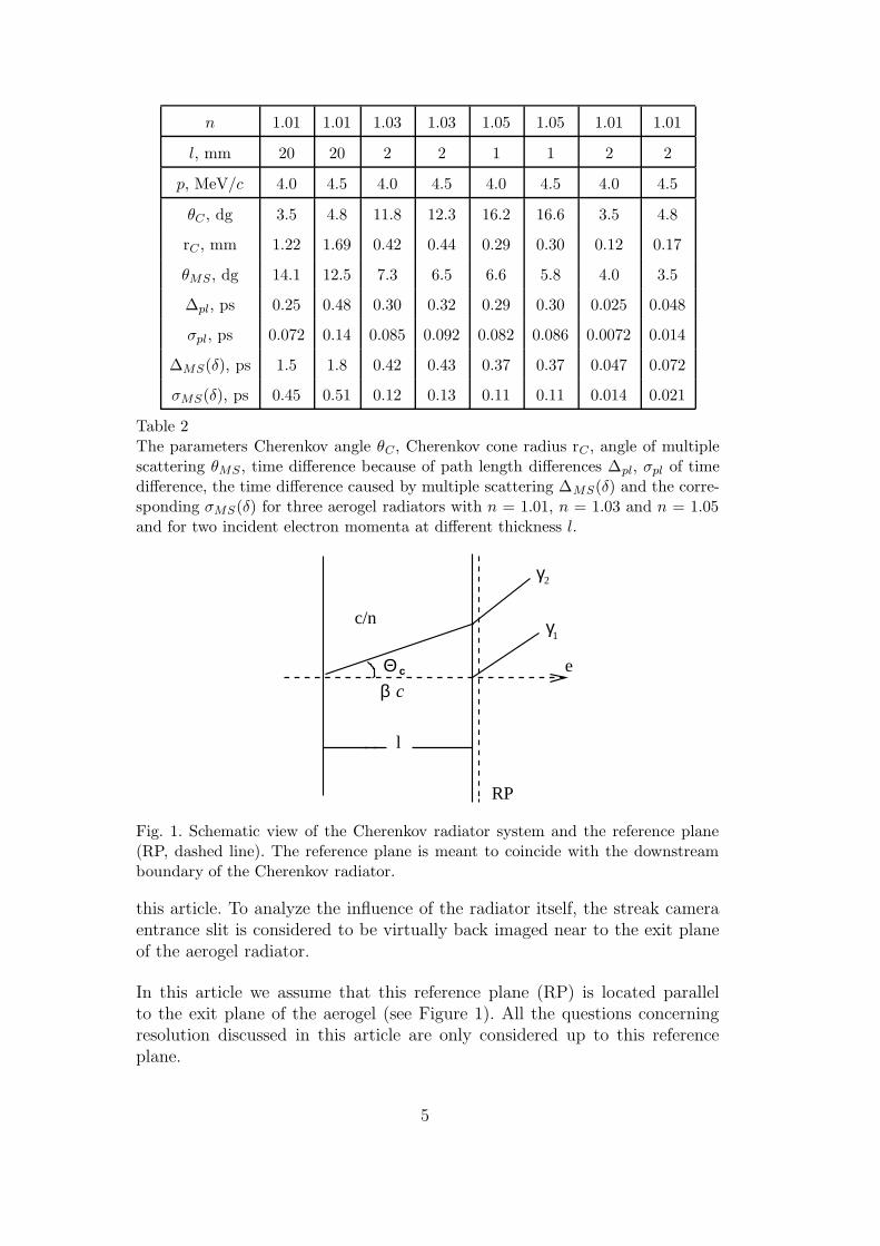
Table 2The parameters Cherenkov angle θC , Cherenkov cone radius rC , angle of multiplescattering θMS , time difference because of path length differences ∆pl, σpl of timedifference, the time difference caused by multiple scattering ∆MS(δ) and the corre-sponding σMS(δ) for three aerogel radiators with n = 1.01, n = 1.03 and n = 1.05and for two incident electron momenta at different thickness l.
c/n
l
Θ
γ
γ
β cc e
RP
2
1
Fig. 1. Schematic view of the Cherenkov radiator system and the reference plane(RP, dashed line). The reference plane is meant to coincide with the downstreamboundary of the Cherenkov radiator.
this article. To analyze the influence of the radiator itself, the streak cameraentrance slit is considered to be virtually back imaged near to the exit planeof the aerogel radiator.
In this article we assume that this reference plane (RP) is located parallelto the exit plane of the aerogel (see Figure 1). All the questions concerningresolution discussed in this article are only considered up to this referenceplane.
5
3.2 Thickness of Aerogel
Beside the refractive index n also the thickness of aerogel l is an importantparameter for the time resolution. The optimal thickness in a real experimenthas to be chosen as a compromise between two contradictory requirements. Toimprove the signal-to-noise ratio of the Cherenkov light detection taking intoaccount light losses along the optical transmission line the radiator thicknesshas to be increased to produce more photons. But for improving the timeresolution of aerogel the radiator thickness is preferred to be small, as it willbe shown in the next paragraphs. Two cases are considered:
(A) Large thickness.For comparison of aerogel samples with different n the thickness will bechosen such that the number of Cherenkov photons is equal. It meansthat
l
(
1 −1
n2β2
)
= const. (5)
Aerogels with n = 1.01, n = 1.03, n = 1.05 will be considered. For n = 1.01the optimal thickness is chosen to be about l = 20mm (see chapter 2.2).According to equation (5) the rounded thickness for the other radia-tors was chosen accordingly: for n = 1.03 l = 2mm and for n = 1.05l = 1mm.
(B) Small thickness (for comparison).Calculations for aerogel with n = 1.01 and l = 2mm will be performed.The number of Cherenkov photons will be 10 times smaller in this casecompared to case (A).
Modern technology gives the possibility to produce aerogel of such thickness.
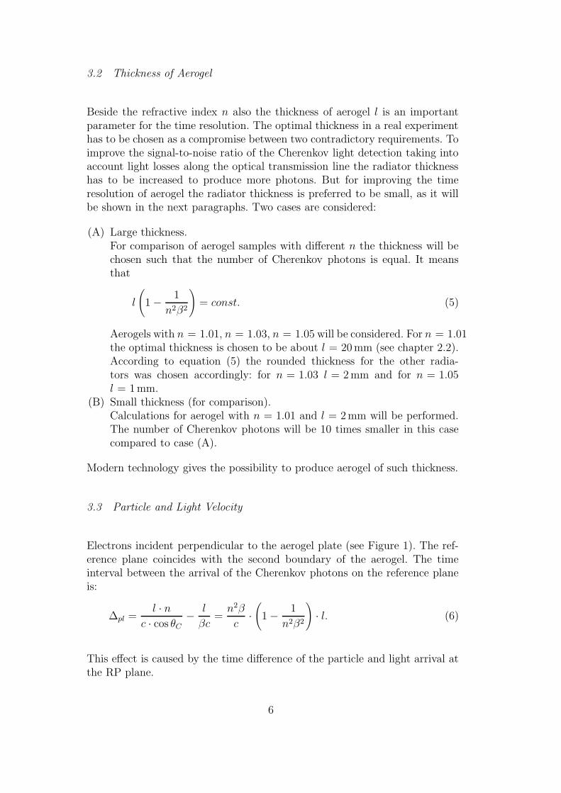
3.3 Particle and Light Velocity
Electrons incident perpendicular to the aerogel plate (see Figure 1). The ref-erence plane coincides with the second boundary of the aerogel. The timeinterval between the arrival of the Cherenkov photons on the reference planeis:
∆pl =l · n
c · cos θC
−l
βc=
n2β
c·(
1 −1
n2β2
)
· l. (6)
This effect is caused by the time difference of the particle and light arrival atthe RP plane.
6

For n = const. ∆pl is proportional to l. This means that one can improve thetime resolution by decreasing the thickness.
The time distribution of the Cherenkov photon bunch has a rectangular shape(see Figure 2, where t1 = l
β·cand t2 = l·n
c·cos θC), therefore the mean squared
dispersion in time is σpl =∆pl√
12.
The numerical values of the ∆pl and σpl are summarized in Table 2.
2
dNdt
ph
t tt
1
Fig. 2. Schematic view of the Cherenkov photon time distribution.
3.4 Dispersion of Refractive Index
To study the dependence of the time resolution on the wavelength it is con-venient to write (6) in the form:
∆pl =βl
c
(
n2 −1
β2
)
(7)
The relative change for two different wavelengths is given by
δ(λ1, λ2) =∆pl(λ1) − ∆pl(λ2)
∆pl(λ1)=
n2(λ1) − n2(λ2)
n2(λ1) − 1β2
. (8)
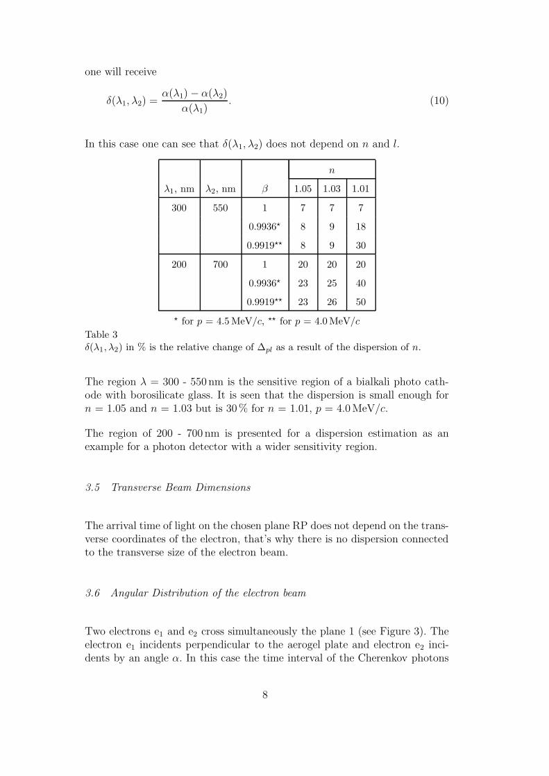
One can see that δ(λ1, λ2) does not depend on l. Some results of the calculationfor aerogel with equation (8) are presented in Table 3 basing on quartz datafrom [12]. If one works far from the threshold for Cherenkov radiation β � 1/nand one uses
n2 = 1 + αρ (9)
7
one will receive
δ(λ1, λ2) =α(λ1) − α(λ2)
α(λ1). (10)
In this case one can see that δ(λ1, λ2) does not depend on n and l.
n
λ1, nm λ2, nm β 1.05 1.03 1.01
300 550 1 7 7 7
0.9936? 8 9 18
0.9919?? 8 9 30
200 700 1 20 20 20
0.9936? 23 25 40
0.9919?? 23 26 50
? for p = 4.5 MeV/c, ?? for p = 4.0 MeV/c
Table 3δ(λ1, λ2) in % is the relative change of ∆pl as a result of the dispersion of n.
The region λ = 300 - 550 nm is the sensitive region of a bialkali photo cath-ode with borosilicate glass. It is seen that the dispersion is small enough forn = 1.05 and n = 1.03 but is 30% for n = 1.01, p = 4.0MeV/c.
The region of 200 - 700 nm is presented for a dispersion estimation as anexample for a photon detector with a wider sensitivity region.
3.5 Transverse Beam Dimensions
The arrival time of light on the chosen plane RP does not depend on the trans-verse coordinates of the electron, that’s why there is no dispersion connectedto the transverse size of the electron beam.
3.6 Angular Distribution of the electron beam
Two electrons e1 and e2 cross simultaneously the plane 1 (see Figure 3). Theelectron e1 incidents perpendicular to the aerogel plate and electron e2 inci-dents by an angle α. In this case the time interval of the Cherenkov photons
8
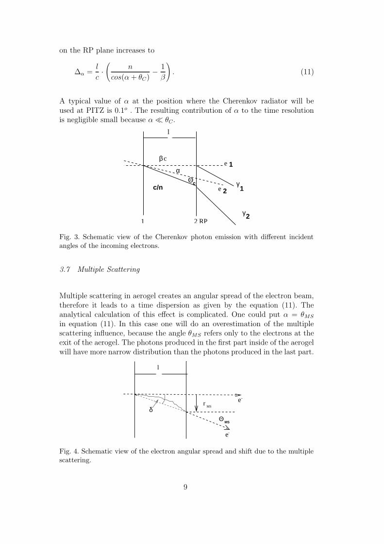
on the RP plane increases to
∆α =l
c·(
n
cos(α + θC)−
1
β
)
. (11)
A typical value of α at the position where the Cherenkov radiator will beused at PITZ is 0.1o . The resulting contribution of α to the time resolutionis negligible small because α � θC .
l
1 2 RP
e
ce
c
γ
γ
β
αΘ
c/n 1
2
1
2
Fig. 3. Schematic view of the Cherenkov photon emission with different incidentangles of the incoming electrons.
3.7 Multiple Scattering
Multiple scattering in aerogel creates an angular spread of the electron beam,therefore it leads to a time dispersion as given by the equation (11). Theanalytical calculation of this effect is complicated. One could put α = θMS
in equation (11). In this case one will do an overestimation of the multiplescattering influence, because the angle θMS refers only to the electrons at theexit of the aerogel. The photons produced in the first part inside of the aerogelwill have more narrow distribution than the photons produced in the last part.
e
e
MS
l
e
rMS
Θδ
Fig. 4. Schematic view of the electron angular spread and shift due to the multiplescattering.
9
The mean squared value of the trajectory shift is rMS = 1√
3· θMS · l [11] (see
Figure 4). Lets introduce an angle δ, so that tgδ = rMS
l= 1
√
3· θMS and lets
assume that α = δ. The value of ∆MS(δ) = lc·(
ncos(δ+θC)
− 1β
)
is presented inTable 2. It is seen that thin aerogel radiators and the use of aerogel with highindex of refraction is preferred.
In Table 2 an estimation of σMS(δ) which is defined as σMS(δ) ≈ ∆MS(δ)/√
12is included. For n = 1.05, n = 1.03, and n = 1.01 with l = 2mm the influenceof multiple scattering is small, therefore the shape of the time spectrum isapproximately rectangular. For n = 1.01 with l = 20mm it is a rough estima-tion.
The data from Table 2 shows, that aerogel with n = 1.01, l = 2mm gives thepossibility to reach a time resolution σMS(δ) = 0.02 ps. Aerogel with n = 1.05,l = 1mm gives 10 times more photons and σMS(δ) = 0.1 ps, whereas aerogelwith n = 1.05, l = 10mm would give 100 times more photons and σMS(δ) =2ps.
3.8 Other Effects
Rayleigh scattering of Cherenkov photons inside aerogel is not considered.The scattered photons would have a wide angular distribution and only asmall part of them would be within the acceptance of an optical transmissionline.
The effect of energy loss due to ionization and Bremsstrahlung is negligi-ble small. Compton scattering of Cherenkov photons is much smaller thanRayleigh scattering therefore this effect gives a negligible contribution to thetime resolution. Scattering of photons on the boundary of aerogel is not con-sidered because the index of refraction is small.
4 Time Resolution. Monte Carlo Results
4.1 Simulation conditions
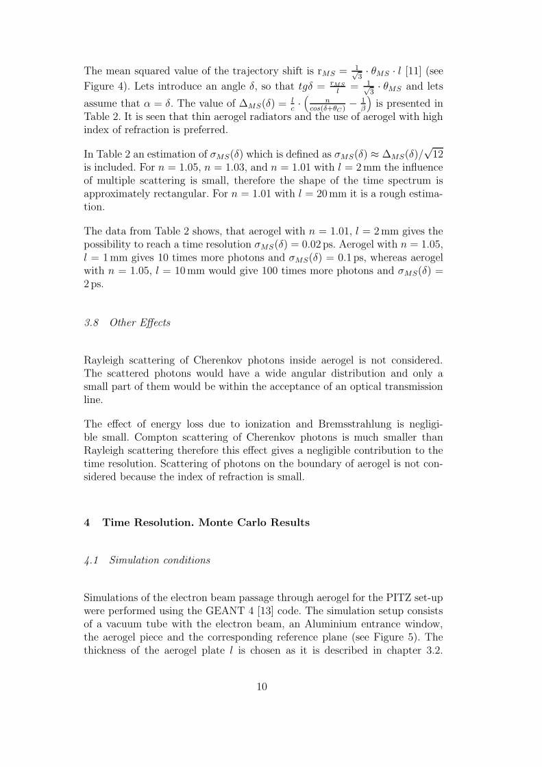
Simulations of the electron beam passage through aerogel for the PITZ set-upwere performed using the GEANT 4 [13] code. The simulation setup consistsof a vacuum tube with the electron beam, an Aluminium entrance window,the aerogel piece and the corresponding reference plane (see Figure 5). Thethickness of the aerogel plate l is chosen as it is described in chapter 3.2.
10
Aerogel materials (SiO2) with index of refraction of 1.01, 1.03 and 1.05 areinvestigated. In front of the aerogel a 20µm thick Aluminium window canbe positioned. This window will be used in the experiment to protect therest of the PITZ vacuum system from outgasing particles from aerogel. Anideal photon detector is placed behind the aerogel at the reference plane asdescribed above (see chapter 3.1).
l
e
vacuum
Al window RP
aerogel
Fig. 5. Schematic view of the geometry of the GEANT 4 input.
Electrons produce Cherenkov photons inside the aerogel in a wavelength rangeof 350 to 800 nm. The GEANT program was configured to do a Cherenkovlight simulation without wavelength dependence of the refractive index andassuming a photon detection efficiency of 100 percent. The physical processesinclude Cherenkov effect, Rayleigh scattering, multiple scattering, ionizationand Bremsstrahlung. These processes are switched on one after another. Noabsorption and reflection of the Cherenkov light at the boundaries of theaerogel were considered.
4.2 Acceptance model of the Optical Transmission Line
To estimate the needed acceptance of the optical transmission line behind theaerogel plate the transverse distribution of the photon emission points fromthe aerogel backplane and the angular distribution of the emitted photonsare calculated for different processes. Both distributions are calculated withrespect to the incident electron position and direction.
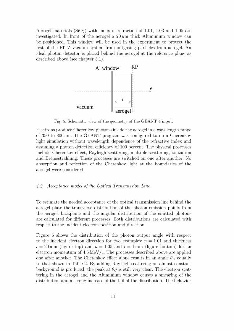
Figure 6 shows the distribution of the photon output angle with respectto the incident electron direction for two examples: n = 1.01 and thicknessl = 20mm (figure top) and n = 1.05 and l = 1mm (figure bottom) for anelectron momentum of 4.5MeV/c. The processes described above are appliedone after another. The Cherenkov effect alone results in an angle θC equallyto that shown in Table 2. By adding Rayleigh scattering an almost constantbackground is produced, the peak at θC is still very clear. The electron scat-tering in the aerogel and the Aluminium window causes a smearing of thedistribution and a strong increase of the tail of the distribution. The behavior
11
o / Θ0 5 10 15 20 25 301
10
102
103
104
105
106 +Ray
+MS +Al
Θ dΘdP/sin
o / Θ0 5 10 15 20 25 301
10
102
103
104
105
106
+Ray +MS +Al
Θ dΘdP/sin
Fig. 6. Distribution of the Cherenkov photon bunches output angle with respect tothe incident electron direction for n = 1.01 and thickness l = 20 mm (upper figure)and n = 1.05 and l = 1 mm (lower figure) for an electron momentum of 4.5 MeV/c.+Ray means just considering the Cherenkov effect and Rayleigh scattering. +MSmeans the inclusion of multiple scattering and +Al that of the Aluminium window.Here the processes are added one after another.
is similar for aerogel of different refractive indices and thicknesses except thatthe Cherenkov angle peak occurs at different angles.
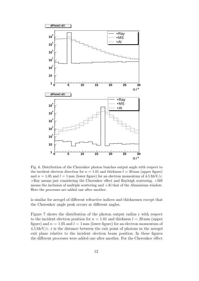
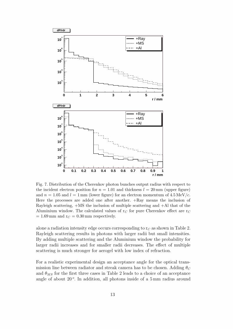
Figure 7 shows the distribution of the photon output radius r with respectto the incident electron position for n = 1.01 and thickness l = 20mm (upperfigure) and n = 1.05 and l = 1mm (lower figure) for an electron momentum of4.5MeV/c. r is the distance between the exit point of photons in the aerogelexit plane relative to the incident electron beam position. In these figuresthe different processes were added one after another. For the Cherenkov effect
12
r / mm0 1 2 3 4 5 6
103
104
105
106
107 +Ray
+MS +Al
dP/rdr
r / mm0 0.1 0.2 0.3 0.4 0.5 0.6 0.7 0.8 0.9 1
102
103
104
105
106
107
108
+Ray +MS +Al
dP/rdr
Fig. 7. Distribution of the Cherenkov photon bunches output radius with respect tothe incident electron position for n = 1.01 and thickness l = 20 mm (upper figure)and n = 1.05 and l = 1 mm (lower figure) for an electron momentum of 4.5 MeV/c.Here the processes are added one after another. +Ray means the inclusion ofRayleigh scattering, +MS the inclusion of multiple scattering and +Al that of theAluminium window. The calculated values of rC for pure Cherenkov effect are rC
= 1.69 mm and rC = 0.30 mm respectively.
alone a radiation intensity edge occurs corresponding to rC as shown in Table 2.Rayleigh scattering results in photons with larger radii but small intensities.By adding multiple scattering and the Aluminium window the probability forlarger radii increases and for smaller radii decreases. The effect of multiplescattering is much stronger for aerogel with low index of refraction.
For a realistic experimental design an acceptance angle for the optical trans-mission line between radiator and streak camera has to be chosen. Adding θC
and θMS for the first three cases in Table 2 leads to a choice of an acceptanceangle of about 20 o. In addition, all photons inside of a 5mm radius around
13

t / ps90 90.5 91 91.5 92 92.5 930
10000
20000
30000
40000
50000 n = 1.01
n = 1.05
Fig. 8. Time distribution of Cherenkov photon bunches produced by electronbunches of 4.5 MeV/c momentum, fixed electron direction and point-like source,no consideration of Rayleigh scattering, multiple scattering and Aluminium win-dow. The thickness of the aerogel samples is 20 mm for n = 1.01 and 1 mm for n =1.05.
the initial electron direction are accepted, because the typical electron beamsize at PITZ is smaller than this transverse size. This choice of cuts in angleand radius includes the peaks and edges seen in the Figures 6 and 7, thereforemost photons are collected. The following simulations are shown assumingthese acceptance cuts.
4.3 Particle and Light Velocity
To study the influence of different effects on the time resolution, simulationswere performed step by step adding new phenomena to be considered in thesimulation. The simplest case is when the bunch length is set to be zero andall electrons are assumed to have the same momentum, no Aluminium win-dow is in front of the aerogel and neglecting all electron interactions exceptthe Cherenkov radiation. The electrons incident angle is perpendicular to theaerogel plate.
Figure 8 shows the time distribution of Cherenkov photons produced by elec-
14
tron bunches of 4.5MeV/c momentum and arriving at the photon receiverplane for aerogels with n = 1.01 and n = 1.05 within the acceptance angle.The simulation time clock starts when the electrons start to move and endswhen the photons, produced by the electrons, reach the photon receiver. Thistime distribution has a rectangular shape as expected from Figure 2. TheFWHM of these distributions is in agreement with the theoretical calculationof ∆pl (see Table 2.). The simulated Cherenkov angle θC and cone radius rC
coincide with the expected values (see Figure 6 and 7).
The integral of the distribution shown in Figure 8 is proportional to theamount of emitted Cherenkov photons. These integrals are not equal forboth distributions because the thickness was optimized for a momentum of4MeV/c.
4.4 Rayleigh Scattering
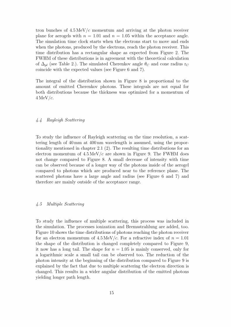
To study the influence of Rayleigh scattering on the time resolution, a scat-tering length of 40mm at 400 nm wavelength is assumed, using the propor-tionality mentioned in chapter 2.1 (2). The resulting time distributions for anelectron momentum of 4.5MeV/c are shown in Figure 9. The FWHM doesnot change compared to Figure 8. A small decrease of intensity with timecan be observed because of a longer way of the photons inside of the aerogelcompared to photons which are produced near to the reference plane. Thescattered photons have a large angle and radius (see Figure 6 and 7) andtherefore are mainly outside of the acceptance range.
4.5 Multiple Scattering
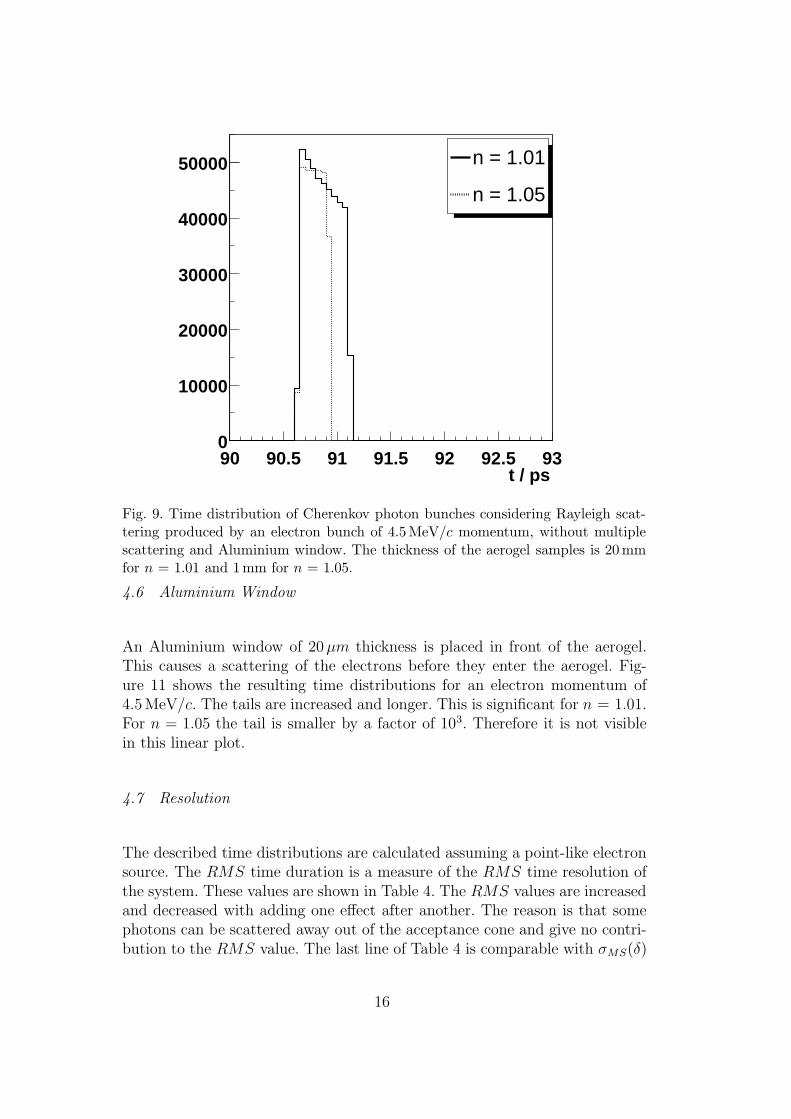
To study the influence of multiple scattering, this process was included inthe simulation. The processes ionization and Bremsstrahlung are added, too.Figure 10 shows the time distributions of photons reaching the photon receiverfor an electron momentum of 4.5MeV/c. For a refractive index of n = 1.01the shape of the distribution is changed completely compared to Figure 9,it now has a long tail. The shape for n = 1.05 is mainly conserved, only fora logarithmic scale a small tail can be observed too. The reduction of thephoton intensity at the beginning of the distribution compared to Figure 9 isexplained by the fact that due to multiple scattering the electron direction ischanged. This results in a wider angular distribution of the emitted photonsyielding longer path length.
15
t / ps90 90.5 91 91.5 92 92.5 930
10000
20000
30000
40000
50000 n = 1.01
n = 1.05
Fig. 9. Time distribution of Cherenkov photon bunches considering Rayleigh scat-tering produced by an electron bunch of 4.5 MeV/c momentum, without multiplescattering and Aluminium window. The thickness of the aerogel samples is 20 mmfor n = 1.01 and 1mm for n = 1.05.
4.6 Aluminium Window
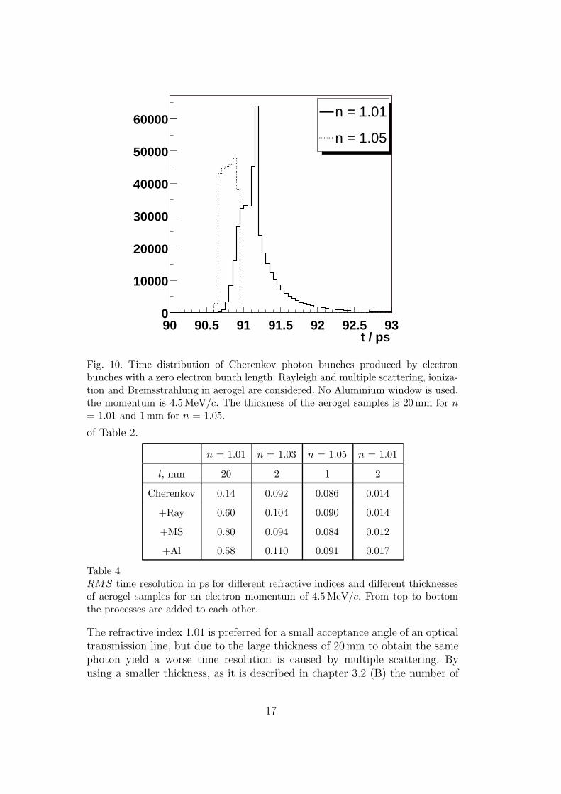
An Aluminium window of 20µm thickness is placed in front of the aerogel.This causes a scattering of the electrons before they enter the aerogel. Fig-ure 11 shows the resulting time distributions for an electron momentum of4.5MeV/c. The tails are increased and longer. This is significant for n = 1.01.For n = 1.05 the tail is smaller by a factor of 103. Therefore it is not visiblein this linear plot.
4.7 Resolution
The described time distributions are calculated assuming a point-like electronsource. The RMS time duration is a measure of the RMS time resolution ofthe system. These values are shown in Table 4. The RMS values are increasedand decreased with adding one effect after another. The reason is that somephotons can be scattered away out of the acceptance cone and give no contri-bution to the RMS value. The last line of Table 4 is comparable with σMS(δ)
16
t / ps90 90.5 91 91.5 92 92.5 930
10000
20000
30000
40000
50000
60000 n = 1.01
n = 1.05
Fig. 10. Time distribution of Cherenkov photon bunches produced by electronbunches with a zero electron bunch length. Rayleigh and multiple scattering, ioniza-tion and Bremsstrahlung in aerogel are considered. No Aluminium window is used,the momentum is 4.5 MeV/c. The thickness of the aerogel samples is 20 mm for n
= 1.01 and 1mm for n = 1.05.
of Table 2.
n = 1.01 n = 1.03 n = 1.05 n = 1.01
l, mm 20 2 1 2
Cherenkov 0.14 0.092 0.086 0.014
+Ray 0.60 0.104 0.090 0.014
+MS 0.80 0.094 0.084 0.012
+Al 0.58 0.110 0.091 0.017
Table 4RMS time resolution in ps for different refractive indices and different thicknessesof aerogel samples for an electron momentum of 4.5 MeV/c. From top to bottomthe processes are added to each other.
The refractive index 1.01 is preferred for a small acceptance angle of an opticaltransmission line, but due to the large thickness of 20mm to obtain the samephoton yield a worse time resolution is caused by multiple scattering. Byusing a smaller thickness, as it is described in chapter 3.2 (B) the number of
17
t / ps90 90.5 91 91.5 92 92.5 930
10000
20000
30000
40000
50000n = 1.01
n = 1.05
Fig. 11. Time distribution of Cherenkov photon bunches produced by electronbunches with zero electron bunch length. Rayleigh and multiple scattering, ion-ization and Bremsstrahlung and a 20 µm thick Aluminium window are consideredfor an electron momentum of 4.5 MeV/c. The thickness of the aerogel samples is20 mm for n = 1.01 and 1mm for n = 1.05.
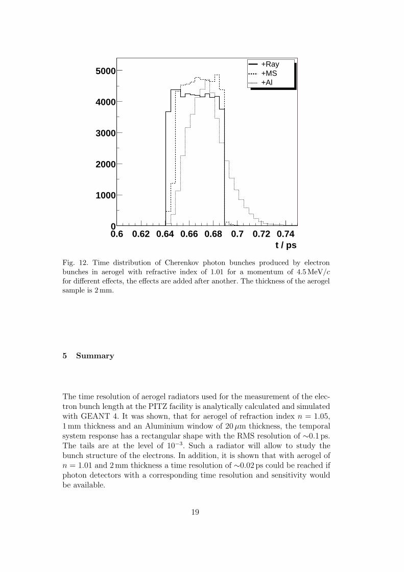
photons is decreased by a factor of 10. Figure 12 shows the time distribution fordifferent processes, the time range is much smaller than for the thicker aerogelwith n = 1.01. The corresponding time resolutions are also shown in Table4. One can see that aerogel gives the possibility to reach a time resolution of0.02 ps. This time resolution can be reached if the detector is able to detectthe weak signal.
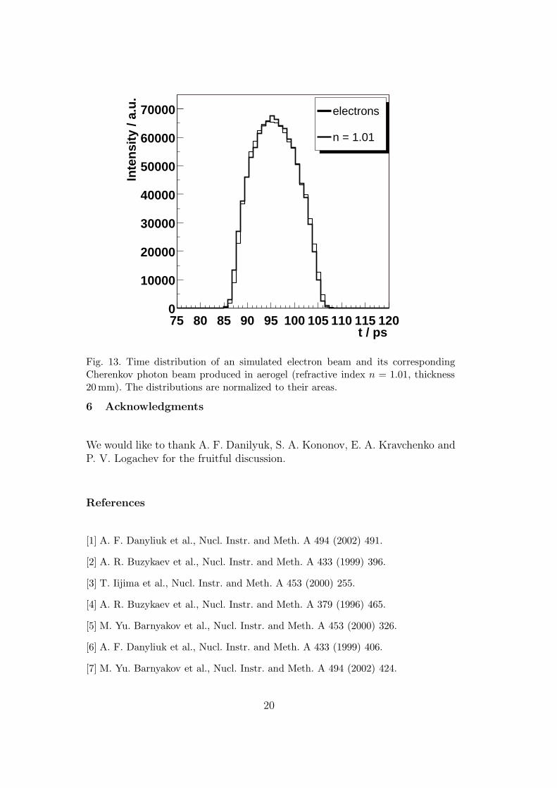
To determine how the proposed system will measure the bunch length distri-bution, an electron beam simulated with ASTRA [14] is used as input for theGEANT 4 simulation. The beam has a transverse size of RMSx,y = 2.3mmand an angle distribution of RMSx′,y′ = 1.6mrad with a mean momentum of4.54MeV/c and a momentum spread of 1.4%.
The example shown in Figure 13 is for the worst case of time resolution forn = 1.01 and thickness l = 20mm. The thick solid line represents the timedistribution of the electron beam, the thin line shows the time distributionproduced by Cherenkov photons in aerogel. Only small differences can beseen. The distributions for the other considered aerogels matches even betterto the electron beam temporal distribution.
18
t / ps0.6 0.62 0.64 0.66 0.68 0.7 0.72 0.740
1000
2000
3000
4000
5000 +Ray +MS +Al
Fig. 12. Time distribution of Cherenkov photon bunches produced by electronbunches in aerogel with refractive index of 1.01 for a momentum of 4.5 MeV/cfor different effects, the effects are added after another. The thickness of the aerogelsample is 2 mm.
5 Summary
The time resolution of aerogel radiators used for the measurement of the elec-tron bunch length at the PITZ facility is analytically calculated and simulatedwith GEANT 4. It was shown, that for aerogel of refraction index n = 1.05,1mm thickness and an Aluminium window of 20µm thickness, the temporalsystem response has a rectangular shape with the RMS resolution of ∼0.1 ps.The tails are at the level of 10−3. Such a radiator will allow to study thebunch structure of the electrons. In addition, it is shown that with aerogel ofn = 1.01 and 2mm thickness a time resolution of ∼0.02 ps could be reached ifphoton detectors with a corresponding time resolution and sensitivity wouldbe available.
19
t / ps75 80 85 90 95 100 105 110 115 120
Inte
nsi
ty /
a.u
.
0
10000
20000
30000
40000
50000
60000
70000 electrons
n = 1.01
Fig. 13. Time distribution of an simulated electron beam and its correspondingCherenkov photon beam produced in aerogel (refractive index n = 1.01, thickness20 mm). The distributions are normalized to their areas.
6 Acknowledgments
We would like to thank A. F. Danilyuk, S. A. Kononov, E. A. Kravchenko andP. V. Logachev for the fruitful discussion.
References
[1] A. F. Danyliuk et al., Nucl. Instr. and Meth. A 494 (2002) 491.
[2] A. R. Buzykaev et al., Nucl. Instr. and Meth. A 433 (1999) 396.
[3] T. Iijima et al., Nucl. Instr. and Meth. A 453 (2000) 255.
[4] A. R. Buzykaev et al., Nucl. Instr. and Meth. A 379 (1996) 465.
[5] M. Yu. Barnyakov et al., Nucl. Instr. and Meth. A 453 (2000) 326.
[6] A. F. Danyliuk et al., Nucl. Instr. and Meth. A 433 (1999) 406.
[7] M. Yu. Barnyakov et al., Nucl. Instr. and Meth. A 494 (2002) 424.
20
[8] T. Iijima et al., Tests of a proximity focusing RICH with aerogel as radiator, talkpresented at RICH 2002, to be published at Nucl. Instr. and Meth.
[9] I. M. Frank, I. E. Tamm, Dokl. Akad. NAuk, SSSR (1937) 14(3) 109.
[10] ’Photomultiplier Tubes’, Catalog TPM0003E02, Hamamatsu, Oct. 1998 T.(1998)
[11] K. Hagiwara et al., Particle Data Group, Physical Review D66, 010001 (2002)
[12] F. Kohlrausch, Teubner Verlag, ISBN 3-519-23000-3 (1996)
[13] GEANT 4, http://wwwinfo.cern.ch/asd/geant4/geant4.html
[14] K. Flottmann, ”A Space Charge Tracking Algorithm”,http: //www.desy.de/∼mpyflo/.
21