Embed Size (px)
Citation preview

Datasheet: QCI-DS033 QuickSilver Controls, Inc. Date: 2 May 2018 www.QuickSilverControls.com
Property of QuickSilver Controls, Inc. Page 1 of 26 This document is subject to change without notice. QuickControl® and QCI® are Registered Trademarks of QuickSilver Controls, Inc. SilverMax™, PVIA™, QuickSilver Controls™, and AntiHunt™ are trademarks of QuickSilver Controls, Inc..
SilverMax™ 34 Frame X-Series The SilverMax™ is a fully integrated Hybrid Servo Motor with feedback, a Controller/Indexer, and a Digital Driver in a compact package. All communications and IO are accessed through a single 19 pin M16 connector. Power and external Clamp resistor are available through a 6 pin M23 connector. The interface includes 7 I/O, all of which support both LVTTL and analog signals, and one of which also supports 0 to 10v analog input. A processor back-up power input and a hardware drive enable are also included. Communication via CANopen and RS-485 serial, which may be operated simultaneously. The driver is rated to 20A continuous per phase. The system is designed for use at +12.5 to +72 VDC for driver power and 12-48v for processor power. The X34 Silvermax series includes dual internal clamp circuits. An external primary clamp allows the clamp resistor to be connected externally to handle the required power level. A secondary internal clamp comes on at a slightly higher internal voltage to protect the driver if the primary clamp is not connected, and for those low inertia designs and or lower speeds, or which are not back-driven, the 50w internal clamp may eliminate the need for an external clamp resistor, according to the application. (Note: resistors are 50W average, allow up to 250W for up to 5 seconds) Requires QuickControl v6.24 or greater to initialize and program SilverMax servo.

Datasheet:QCI-DS033 QuickSilver Controls, Inc.
QuickSilver Controls, Inc. Page 2 of 26
System Overview Point-to-Point Moves
• Relative or Absolute
• Velocity or Time Based
• S-Curve Advanced Motion Profile Moves
• Profile Move Commands
• Register Based o Position/Accel/Decel/Velocity o Modify On-the-Fly
Input/Output
• 7 LVTTL Digital I/O o Bi-Directional o Set While In Motion
• 7 Analog Inputs (Joystick)
• 1 Analog 0-10v Input
• 1 Output supports PWM out
• Programmable Logic Switch out
• Secondary Encoder In
• Encoder Out (single ended and differential
Program and Data Storage
• 32K Non-Volatile Memory:
• 8191 word command buffer
• 2000-3000 Program Lines
• 4K User Registers
• User Data Examples o CAM Tables o Motion Profiles o Lookup Tables
Electronic Gearing/Camming
• Follow External Signals o Encoder (A/B Quadrature) o Step and Direction
• Gearing plus Trapezoid motion
• Electronic Cam o Import Cam Table from File
• Gearing with extended precision: o A/B gearing o xxx.xxxxxxxx multiplier
Electronic Slip Clutch/Brake
• Variable Torque
• Wind/Unwind Applications Communications
• RS-485 @ up to 230K Baud
• ASCII, Binary, Modbus®, DMX512
• Host Control While Servo in Motion
• CANopen® (Rev 03 SW and higher) Programming Language
• Easy, Menu Driven Interface
• Command Parameter Prompts
• No Syntax Errors
• User Namable I/O and Registers Advance PVIA™ Servo Loop
• Improvement Stability
• Simulated Viscous Inertial Damper
• 100:1 Inertial Mismatch
• Direct Drive Oversized Inertial Loads o Flywheels o Belt Drives o Typically eliminates need for
Gearheads Anti-Hunt™
• Optionally transition to open loop while in position – automatically changes back to full servo if position is disturbed.
• No Servo Dither While at Rest Multi-Task/Multi-Thread
• Two programs plus a motion simultaneously
• Multiple background protection settings
Based on QCI’s Hybrid Servo Motors: NEMA 34 Frame
o 16000 Counts/Rev Encoder o Up to 2600 oz-in (18.6 Nm)
(continuous)
(8 places behind decimal point)
Datasheet:QCI-DS033 QuickSilver Controls, Inc.
QuickSilver Controls, Inc. Page 3 of 26
Specifications
X34CK-1 X34CK-2 X34CT-1 X34HC-1 X34HC-2 X34HC-3 X34HC-4
Maximum Speed (RPM) 2000 1500 2500 3000 2500 2000 2000
48v Optimal Speed (RPM) 700 450 1200 1300 900 900 1000
Torque (oz-in / Nm) at Optimal Speed
295 2.1
535 3.8
320 2.3
470 3.3
800 5.65
874 6.17
750 5.29
Continuous Stall Torque oz-in / Nm
490 3.4
1050 7.4
540 3.7
690 4.8
1300 9.3
2000 14.1
2600 18.6
Peak Power (Mech. Watts) @ 48v **
150 175 285 420 596 585 555
Rotor Inertia oz-in2 / Kg-m2
7.65 1.4e-4
14.8 2.7e-4
7.65 1.4e-4
7.8 1.4e-4
14.7 2.7e-4
21.9 4.0e-4
29.0 5.3e-4
Weight pounds / Kg
6.1 2.8
9.25 4.2
6.1 2.8
5.9 2.7
9.4 4.3
13 5.9
16 7.25
Maximum Driver Input Current (Amps - DC)
5 6.5 10 14 16 16.5 14
Maximum Radial Force (lbs) / Newtons 0.79’’/ 20mm from mounting face
49 220
49 220
49 220
65 290
65 290
110 490
110 490
Maximum Axial Force (lbs) / Newtons
13.5 60
13.5 60
13.5 60
305 1300
305 1300
305 1300
305 1300
Shaft Diameter in/mm .5
12.7 .5
12.7 .5
12.7 .500
12.70 .500
12.70 .625
15.88 .625
15.88
Notes: ** Max power approximately 1.5 times larger than 48v value when operated at 72v

Datasheet:QCI-DS033 QuickSilver Controls, Inc.
QuickSilver Controls, Inc. Page 4 of 26
0
0.25
0.5
0.75
1
1.25
1.5
1.75
2
2.25
2.5
2.75
3
3.25
3.5
3.75
4
0
100
200
300
400
500
600
0 250 500 750 1000 1250 1500 1750 2000
To
rqu
e (
oz-i
n)
Speed (RPM)
34CK-1 Torque Curve
To
rqu
e-
Nm
0
50
100
150
200
250
0 500 1000 1500 2000
Mech
an
ical
Po
wer
(watt
s)
Speed (RPM)
34CK-1 Power Curve
72V
60V
48V
36V
24V
12.5V

Datasheet:QCI-DS033 QuickSilver Controls, Inc.
QuickSilver Controls, Inc. Page 5 of 26
0
10
20
30
40
50
60
70
80
90
0 500 1000 1500 2000
Speed (RPM)
34CK-1 Efficiency Curve - Motor + Drive
72V
60V
48V
36V
24V
12.5V
Eff
icie
ncy -
%

Datasheet:QCI-DS033 QuickSilver Controls, Inc.
QuickSilver Controls, Inc. Page 6 of 26
0
0.5
1
1.5
2
2.5
3
3.5
4
4.5
0
100
200
300
400
500
600
0 250 500 750 1000 1250 1500 1750 2000 2250 2500
To
rqu
e (
oz-i
n)
Speed (RPM)
X34CT-1 Torque Curve
72V
60V
48V
36V
24V
12.5V
To
rqu
e-
Nm
0
50
100
150
200
250
300
350
400
0 500 1000 1500 2000 2500
Mech
ou
tpu
t p
ow
er
-W
Speed (RPM)
X34CT-1Power Curve
72V
60V
48V
36V
24V
12.5V

Datasheet:QCI-DS033 QuickSilver Controls, Inc.
QuickSilver Controls, Inc. Page 7 of 26
0
10
20
30
40
50
60
70
80
0 500 1000 1500 2000 2500
Eff
icie
ncy -
%
Speed (RPM)
X34CT-1 Efficiency Curve - Motor+Drive
72V
60V
48V
36V
24V
12.5V

Datasheet:QCI-DS033 QuickSilver Controls, Inc.
QuickSilver Controls, Inc. Page 8 of 26
0
0.5
1
1.5
2
2.5
3
3.5
4
4.5
5
5.5
6
6.5
7
7.5
8
0
200
400
600
800
1000
1200
0 100 200 300 400 500 600 700 800 900 1000 1100 1200 1300 1400 1500
To
rqu
e (
oz-i
n)
Speed (RPM)
X34CK-2 Torque Curve72V
60V
48V
36V
24V
12.5V
To
rqu
e-
Nm
0
50
100
150
200
250
300
0 200 400 600 800 1000 1200 1400
Mech
ou
tpu
t p
ow
er
-W
Speed (RPM)
X34CK-2 Power Curve72V
60V
48V
36V
24V
12.5V
Datasheet:QCI-DS033 QuickSilver Controls, Inc.
QuickSilver Controls, Inc. Page 9 of 26
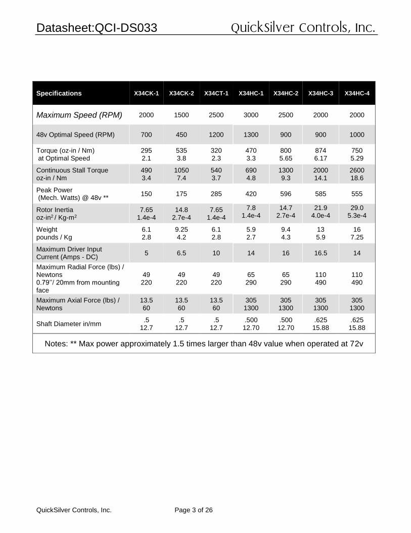
Note: All torque curves taken with 2’ power cable; voltage measured entering power cable.
0
10
20
30
40
50
60
70
80
90
0 200 400 600 800 1000 1200 1400
Eff
icie
ncy -
%
Speed (RPM)
X34CK-2 Efficiency Curve - Motor+Drive
72V
60V
48V
36V
24V
12.5V

Datasheet:QCI-DS033 QuickSilver Controls, Inc.
QuickSilver Controls, Inc. Page 10 of 26
0
1
2
3
4
5
6
7
0
100
200
300
400
500
600
700
800
900
1000
0 250 500 750 1000 1250 1500 1750 2000 2250 2500 2750 3000
To
rqu
e (
oz-i
n)
Speed (RPM)
X34HC-1 Torque Curve
To
rqu
e -
Nm
0
100
200
300
400
500
600
700
0 500 1000 1500 2000 2500 3000
Mech
ou
tpu
t p
ow
er
-W
Speed (RPM)
X34HC-1Power Curve
72V
60V
48V
36V
24V
12.5V

Datasheet:QCI-DS033 QuickSilver Controls, Inc.
QuickSilver Controls, Inc. Page 11 of 26
0
10
20
30
40
50
60
70
80
0 500 1000 1500 2000 2500 3000
Eff
icie
ncy -
%
Speed (RPM)
X34HC-1 Efficiency Curve - Motor+Drive
72V
60V
48V
36V
24V
12.5V

Datasheet:QCI-DS033 QuickSilver Controls, Inc.
QuickSilver Controls, Inc. Page 12 of 26
0
2
4
6
8
10
12
0
200
400
600
800
1000
1200
1400
1600
1800
0 250 500 750 1000 1250 1500 1750 2000 2250 2500
To
rqu
e (
oz-i
n)
Speed (RPM)
X34HC-2 Torque Curve72V Max
72V
60V
48V
36V
24V
12.5V
48V Max
To
rqu
eN
m
0
100
200
300
400
500
600
700
800
900
0 500 1000 1500 2000 2500
Mech
ou
tpu
t p
ow
er
-W
Speed (RPM)
X34HC-2 Power Curve72V
60V
48V
36V
24V
12.5V
Datasheet:QCI-DS033 QuickSilver Controls, Inc.
QuickSilver Controls, Inc. Page 13 of 26
0
10
20
30
40
50
60
70
80
90
0 500 1000 1500 2000 2500
Eff
icie
ncy -
%
Speed (RPM)
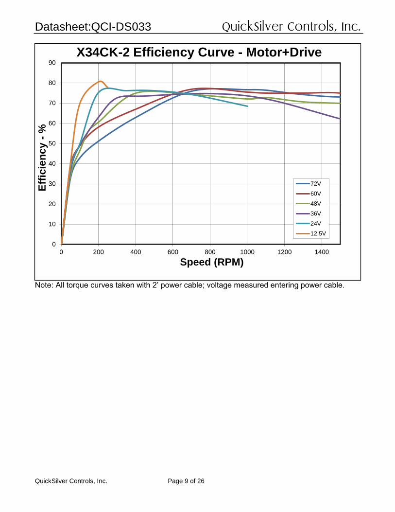
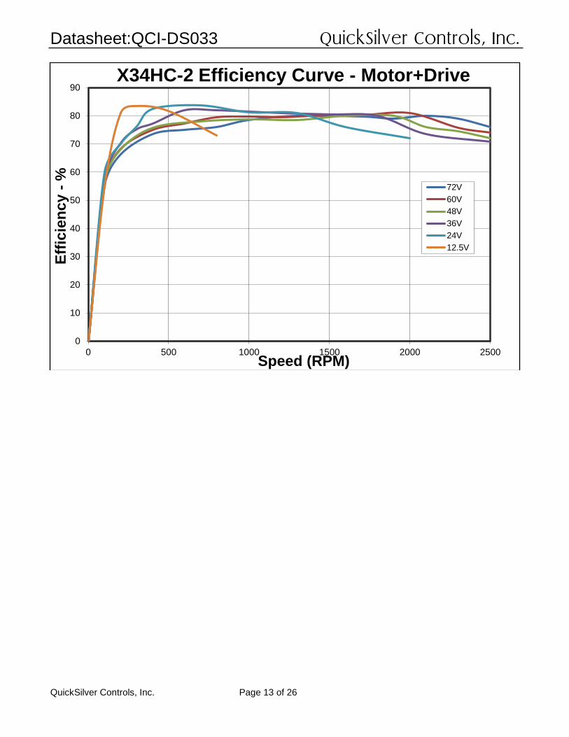
X34HC-2 Efficiency Curve - Motor+Drive
72V
60V
48V
36V
24V
12.5V

Datasheet:QCI-DS033 QuickSilver Controls, Inc.
QuickSilver Controls, Inc. Page 14 of 26
0
2
4
6
8
10
12
14
16
18
0
500
1000
1500
2000
2500
0 250 500 750 1000 1250 1500 1750 2000
To
rqu
e (
oz-i
n)
Speed (RPM)
X34HC-3 Torque Curve72V Max
72V
60V
48V Max
48V
36V
24V
12.5V
To
rqu
e-
Nm
0
100
200
300
400
500
600
700
800
900
0 200 400 600 800 1000 1200 1400 1600 1800 2000
Mech
ou
tpu
t p
ow
er
-W
Speed (RPM)
X34HC-3 Power Curve
72V
60V
48V
36V
24V
12.5V

Datasheet:QCI-DS033 QuickSilver Controls, Inc.
QuickSilver Controls, Inc. Page 15 of 26
0
10
20
30
40
50
60
70
80
90
0 200 400 600 800 1000 1200 1400 1600 1800 2000
Eff
icie
ncy -
%
Speed (RPM)
X34HC-3 Efficiency Curve - Motor+Drive
72V
60V
48V
36V
24V
12.5V

Datasheet:QCI-DS033 QuickSilver Controls, Inc.
QuickSilver Controls, Inc. Page 16 of 26
0
2
4
6
8
10
12
14
16
18
20
0
500
1000
1500
2000
2500
3000
0 200 400 600 800 1000 1200 1400
To
rqu
e (
oz-i
n)
Speed (RPM)
X34HC-4 Torque Curve
72V
60V
48V
36V
24V
12.5V
To
rqu
e-
Nm
0
100
200
300
400
500
600
700
800
900
0 200 400 600 800 1000 1200 1400
Mech
ou
tpu
t p
ow
er
-W
Speed (RPM)
X34HC-4 Power Curve72V
60V
48V
36V
24V
12.5V

Datasheet:QCI-DS033 QuickSilver Controls, Inc.
QuickSilver Controls, Inc. Page 17 of 26
0
10
20
30
40
50
60
70
80
90
0 200 400 600 800 1000 1200 1400
Eff
icie
ncy -
%
Speed (RPM)
X34HC-4 Efficiency Curve - Motor+Drive
72V
60V
48V
36V
24V
12.5V

Datasheet:QCI-DS033 QuickSilver Controls, Inc.
QuickSilver Controls, Inc. Page 18 of 26
SilverMax X-series Interface (SMI)
Input Power Processor Power V+ Processor:+12.5 VDC to +48 VDC, regulated. Processor Power should have no larger than an 8A fuse to limit power. Driver Power V+ Driver: +12.5 VDC to +72 VDC. Device must be initialized for the actual operating voltage. Driver Power, Power Ground, Chassis Ground, Clamp+ and Clamp- are provided on a separate 6 pin M23 connector: The Driver power should be fused with not more than a 25A slow blow fuse unless power supply current is limited to same.
Pin Signal Wire color for QCI-XC-LP-10 1 V+ Clamp Yellow 2 V+ Driver Red 3 Chassis Gnd Drain1 4 V- Clamp Orange 5 V- Driver Black 6 Chassis Gnd Drain2
Built-in Clamps Two stages of Clamp circuits are built into the system. The primary clamp allows the clamp resistor to be mounted external to the system for easy heat elimination. This provides for very large inertias and for systems that are back driven. The secondary clamp provides up to 50W average clamping, and comes on at a slightly higher voltage than the primary clamp, actuating only if the primary clamp is not sufficient or is not connected (or opens). The secondary clamp includes over temperature monitoring to shut down the motor if the internal resistors are dissipating excessive energy. Connecting the Clamp+ and the +VP signals together will
Pin Signal
A V+ Processor
B V+ Processor
C IO7
D IO5
E IO4
F IO2
G IO1
H 485A
I CAN-L
K PGND
L PGND
M Processor Backup Power
N Drive Enable
O IO6
P IO3
R 485B
S Logic Ground
T CAN-H
U +5v

Datasheet:QCI-DS033 QuickSilver Controls, Inc.
QuickSilver Controls, Inc. Page 19 of 26
bypass the internal clamp, to allow regenerated power to be used to recharge batteries, for example. Care must be taken to prevent overvoltage. Processor Backup Power +12 to +48v. Separate processor power input. This input is diode isolated from the processor voltage input to allow a separate battery backup to be provided to the processor to keep encoder information alive when the main power is shut down. This input must be fused no more than 0.5Amp if used. Driver Power Input Current 20 Amps DC maximum for any input voltage, +12.5 VDC to +72 VDC per controller. See particular motor size for details for that motor. This input must be fused no more than 25A slow blow. The Driver Power is isolated from the processor power to minimize the influence of the high currents for the driver upon the input voltages. The processor power and the driver power isolation The processor power and driver power are galvanically isolated. The processor ground, the driver ground, and the chassis ground should be connected at the power supply, with the negative side of the power supply strapped to chassis ground at that point, for best noise characteristics.
Inputs & Outputs Digital Inputs 0 to +3.3 VDC. LVTTL level compatible. All inputs have a light pull-up (~100k ohm to 3.3v). All I/O have an optional programmable pull-up/pull-down of 2.2 k ohm; the source to these resistors may also be floated if no pull-up or pull-down is needed. The seven IO are protected to +/- 40v. 5v output Rated to 100mA. Do not back drive. Do not short out. Digital Output Voltage 0 / +3.3 VDC. Digital Output Current Sinking or Sourcing: 2mA Analog Inputs All 7 I/O may be used as Analog Inputs: 0 to +3.3 VDC input signal range. IO7 has a secondary circuit to handle 0 to +10v input signal range; the input protection will isolate the normal 3.3 v input channel allowing the 0 to 10v operation. Resolution: 12 bits (before filtering) Analog signals are read every servo cycle (120 μsec.) and the converted analog data is processed through a (default) 5 ms filter to reduce noise & transients.

Datasheet:QCI-DS033 QuickSilver Controls, Inc.
QuickSilver Controls, Inc. Page 20 of 26
Drive Enable Input This hardware drive enable input must be connected to +10 VDC to +48 VDC for the drive electronics to be enabled. The Drive enable voltage is measured with respect to the processor power ground, not the driver power ground.
Communications
Serial Interface RS-485 multi-drop, Reduced unit load accommodates up to 255 nodes. Protected up to +/- 70v. Note: RS-485 requires a nominal 120 ohm ½ W termination resistor at each end of the network for longer runs. This termination is not provided onboard and must be provided by the user. Protocols
8-bit ASCII, 9-bit binary, Modbus, and DMX512 Hardware Configuration Settings Available Baud Rates: 2400, 4800, 9600, 19.2k, 28.8k, 57.6k, 115.2k or 230.4k (250k only for DMX512) Data Bits: 8 (9 bits for binary) Stop Bits: 1.5 or 2 Parity Bit: None (Modbus supports None, Even, Odd) CAN interface The CAN bus connection is not isolated, but does include transceivers which have an extended +/- 70v fault protection range. The CANopen® communications protocol allows the unit to function as a master, slave, or peer on a CANopen network. See the CANopen User Manual for details on the CANopen protocol. This protocol operates simultaneously and independently from the standard serial protocols. Note that a 120 ohm ½ W termination resistor is required at each end of the CAN network (only two per system). This termination is not provided onboard the controller and must be provided by the user. For the CAN bus, this termination is not optional. CANopen® and CiA® are registered community trademarks of CAN in Automation e.V.
STATUS LIGHTS Three status lights are provided on the back of the SilverMax. The Comm LED (normally Red) indicates the unit is ready (no program running) by a dim level, it is off between communications if a program is running. It blinks brightly during each incoming communications frame. The Status light (normally Green) varies in intensity with the motor torque (negative torque dimmer, positive torque brighter); if Done Bit is configured the LED lights to indicate Done (See Set Done Bit command), is also used to blink error codes if a fault is detected
Comm Status Power

Datasheet:QCI-DS033 QuickSilver Controls, Inc.
QuickSilver Controls, Inc. Page 21 of 26
(and the Done bit is not configured). The Driver power present LED is normally Green; It becomes amber if driver is disabled (either by hardware or by software).
Environmental Specifications Operational Temperature -20 C to +70 C. Continuous torque curves taken at 20C; derating may be needed at higher temperatures. 100% torque requires motor affixed to thermally conductive structure, and may need additional air flow. Must be verified in final application. Storage Temperature - 40 C to +85 C Humidity Continuous specification is 95% RH non-condensing. Shock Limitation is approximately 50g/11ms. Specifications subject to change without notice. See www.QuickSilverControls.com for current information.

Datasheet:QCI-DS033 QuickSilver Controls, Inc.
QuickSilver Controls, Inc. Page 22 of 26
Mechanical Dimensions – 34HC-x

Datasheet:QCI-DS033 QuickSilver Controls, Inc.
QuickSilver Controls, Inc. Page 23 of 26
Mechanical Dimensions – 34Cx-x
Datasheet:QCI-DS033 QuickSilver Controls, Inc.
QuickSilver Controls, Inc. Page 24 of 26
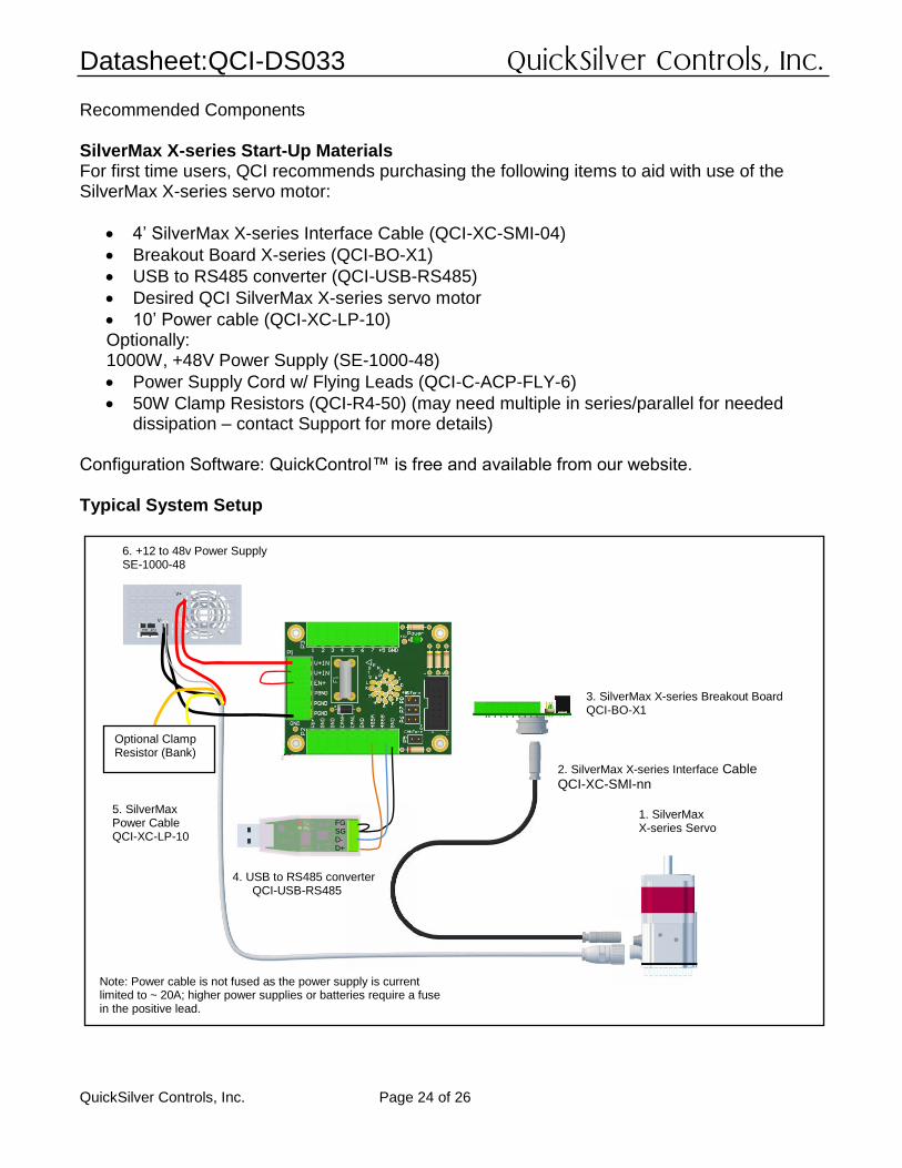
Recommended Components SilverMax X-series Start-Up Materials For first time users, QCI recommends purchasing the following items to aid with use of the SilverMax X-series servo motor:
• 4’ SilverMax X-series Interface Cable (QCI-XC-SMI-04)
• Breakout Board X-series (QCI-BO-X1)
• USB to RS485 converter (QCI-USB-RS485)
• Desired QCI SilverMax X-series servo motor
• 10’ Power cable (QCI-XC-LP-10) Optionally: 1000W, +48V Power Supply (SE-1000-48)
• Power Supply Cord w/ Flying Leads (QCI-C-ACP-FLY-6)
• 50W Clamp Resistors (QCI-R4-50) (may need multiple in series/parallel for needed dissipation – contact Support for more details)
Configuration Software: QuickControl™ is free and available from our website. Typical System Setup
FG SG D- D+
1. SilverMax X-series Servo
2. SilverMax X-series Interface Cable QCI-XC-SMI-nn
3. SilverMax X-series Breakout Board QCI-BO-X1
4. USB to RS485 converter QCI-USB-RS485
6. +12 to 48v Power Supply SE-1000-48
Note: Power cable is not fused as the power supply is current limited to ~ 20A; higher power supplies or batteries require a fuse in the positive lead.
Optional Clamp Resistor (Bank)
5. SilverMax Power Cable QCI-XC-LP-10

Datasheet:QCI-DS033 QuickSilver Controls, Inc.
QuickSilver Controls, Inc. Page 25 of 26
1. SilverMax X-series Servo Motor Motor size based on application requirements. 2. SilverMax X-series Interface Cables The QCI-XC-SMI-nn is used to connect the SilverMax X-series motor to the QCI-BO-X1 breakout board. Replace the last two digits “nn” with length of cable in feet (i.e. –10 for 10 feet). Standard lengths are 4 and 10 feet. The QCI-XC-SMF-nn cable connects to the SMI connector on the SilverMax and provides a pig-tail to allow landing the various signals to your own terminating blocks – see QCI-TD081 for more details. 3. SilverMax X-series Breakout (QCI-BO-X1) QCI recommends purchasing a breakout to simplify wiring power, RS-485 communication, CAN, power backup, drive enable, and 7 LVTTL I/O. The breakouts connect to the SilverMax Interface Cable and includes power fusing. The QCI-BO-X1 is designed to mount through the control housing, providing an IP67 seal for the control housing. See QCI-TD079 for more information. 4. USB to RS485 Converter USB-RS-485 converter provides a USB powered serial port with RS-485 signaling. See QCI-TD073 USB-RS485 Converter Setup Guide for information on network termination and shielding recommendations. 5. SilverMax High Power Cable Provides 4 power connections for V+, V-, and clamp resistor, and a chassis ground connection. 6. Power Supply Power supply selection is motor dependent, but the following will work with all SilverMax X-series 34 frame motors. SE-1000-48 (48V, 20A, 1000 Watt) 7. External Regenerative Clamp Resistor Rapid deceleration of larger loads may require the use of the Primary Clamp circuit, requiring adding external power resistors between Clamp+ and Clamp-. Do not connect Clamp- to Clamp+ except through a clamp resistor of sufficient power rating. Resistance should be such that at operating voltage the resistor current will not exceed 20A when the clamp is active.

Datasheet:QCI-DS033 QuickSilver Controls, Inc.
QuickSilver Controls, Inc. Page 26 of 26
Part Numbers
SilverMax X- Series NEMA 34 Motor Size
Standard: 16000 CPR Encoder 12.5v to 72v for driver, 12-48v for processor Driver Enable CANopen RS-485 – multiple protocols 19 pin M16 Connector 6 pin M23 Power Connector IP65 except for front motor shaft. X34HC-x allow optional shaft seal (add suffix “S” X34Cx-x require shaft seal plate or attachment to sealed gearhead
QCI-X34CK-1
QCI-X34CK-2
QCI-X34CT-1
QCI-X34HC-1
QCI-X34HC-2
QCI-X34HC-3
QCI-X34HC-4
Contact Information QuickSilver Controls, Inc. 990 N Amelia Ave San Dimas, CA 91773 +1 (909) 599-6291 or (888) 660-3801 +1 (909) 599-6289 FAX www.QuickSilverControls.com