Embed Size (px)
Citation preview
SIM Display © 2016 29. December 2016
SIM RACE LCD USER MANUAL
Version 2.0

SIM Display © 2016 29. December 2016
Table of Contents
1 Introduction ......................................................................................................................................... 3
2 USB Connection ................................................................................................................................... 4
2.1 Method #1: Mini USB Connector (Plug and Play) ......................................................................... 4
2.2 Method #2: Manual Connection (Soldering Wires)...................................................................... 5
3 TFT Power Requirements .................................................................................................................... 6
3.1 Method #1: DC Jack Connector .................................................................................................... 6
3.2 Method #2: Manual Connection (Soldering Wires)...................................................................... 7
4 TFT Video Requirements ..................................................................................................................... 8
4.1 Method #1: RCA Connector .......................................................................................................... 8
4.2 Method #2: Manual Connection (Soldering Wires)...................................................................... 9
5 Pushbuttons ....................................................................................................................................... 10
6 Rotary Encoders ................................................................................................................................. 11
7 Rotary Switches ................................................................................................................................. 12
8 Analog Inputs ..................................................................................................................................... 13
8.1 Analog Input Options .................................................................................................................. 13
8.2 Analog Input Requirements ........................................................................................................ 13
9 Realistic F1 Clutch Behavior (BPF) ..................................................................................................... 14
9.1 How Does It Work ....................................................................................................................... 14
9.2 BPF Value Setup (SLIMax Manager Pro) ..................................................................................... 14
10 Wiring Diagram Examples ................................................................................................................ 15
10.1 Pushbutton ............................................................................................................................... 15
10.2 Rotary Encoder ......................................................................................................................... 16
10.3 Potentiometer .......................................................................................................................... 17
10.4 Rotary Switch ............................................................................................................................ 18
10.5 External LEDS ............................................................................................................................ 19
10.6 Complete Wiring ....................................................................................................................... 20
11 Connector (BUTTONS 01-16) ........................................................................................................... 21
12 Connector (BUTTONS 17-32) ........................................................................................................... 22
13 Connector (CLUTCHES | SWITCHES) ................................................................................................ 23

SIM Display © 2016 29. December 2016
1 Introduction
SIM Race LCD (SIMR-LCD) is a replica of real F1 display module. It's also known as shift light
indicator (SLI) and features 15 RPM leds, 6 warning leds and 4 external leds. It must be
connected to the computer's USB port.
The unit includes management of 32 buttons (or maximum 16 rotary encoders), 4 rotary
switches and two analog inputs with true 12-bit resolution (4096 steps). Analog inputs can
be used as clutches, potentiometers, hall sensors and more.
A standalone 4.3" TFT display is embedded with the unit and requires a 12V DC power
supply and a composite video signal (CVBS) from your computer's graphics card.
Modern graphics cards don't support composite video signal anymore, so HDMI CVBS
converter is required between PC and TFT and it must be connected to the computer's HDMI
port.
Note: TFT display will be recognized as an external monitor on your computer.
Note: Brightness of TFT display and LEDS can be adjusted in software.

SIM Display © 2016 29. December 2016
2 USB Connection
SIM Race LCD must be connected to the computer's USB port. It is recognized as a HID
device (plug and play) and it does not require any external drivers to be installed. We
recommend using only high quality USB cables with maximum length of 5 meters.
2.1 Method #1: Mini USB Connector (Plug and Play)
Use standard Mini USB (B) cable and plug it on USB socket on the PCB. The other end must
be connected to the computer's USB port.
SIM Display © 2016 29. December 2016
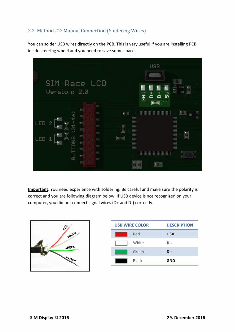
2.2 Method #2: Manual Connection (Soldering Wires)
You can solder USB wires directly on the PCB. This is very useful if you are installing PCB
inside steering wheel and you need to save some space.
Important: You need experience with soldering. Be careful and make sure the polarity is
correct and you are following diagram below. If USB device is not recognized on your
computer, you did not connect signal wires (D+ and D-) correctly.
USB WIRE COLOR DESCRIPTION
Red + 5V
White D -
Green D +
Black GND

SIM Display © 2016 29. December 2016
3 TFT Power Requirements
Voltage Requirement: 12V DC
Current Requirement: 1A (or more)
Plug outside diameter: 5.5mm
Plug inside diameter: 2.5mm
3.1 Method #1: DC Jack Connector
There is a power jack connector available on the PCB for easy and convenient connection.

SIM Display © 2016 29. December 2016
3.2 Method #2: Manual Connection (Soldering Wires)
You can solder DC power wires directly on the PCB. This is very useful if you are installing
PCB inside steering wheel and you need to save some space.
Important: You need experience with soldering. Be careful and make sure the polarity is
correct.

SIM Display © 2016 29. December 2016
4 TFT Video Requirements
Modern graphics cards don't support composite video signal anymore, so HDMI CVBS
converter is required between PC and TFT and it must be connected to the computer's HDMI
port.
4.1 Method #1: RCA Connector
There is a RCA connector available on the PCB for easy and convenient connection. RCA
video (male to male) cable is required.
SIM Display © 2016 29. December 2016
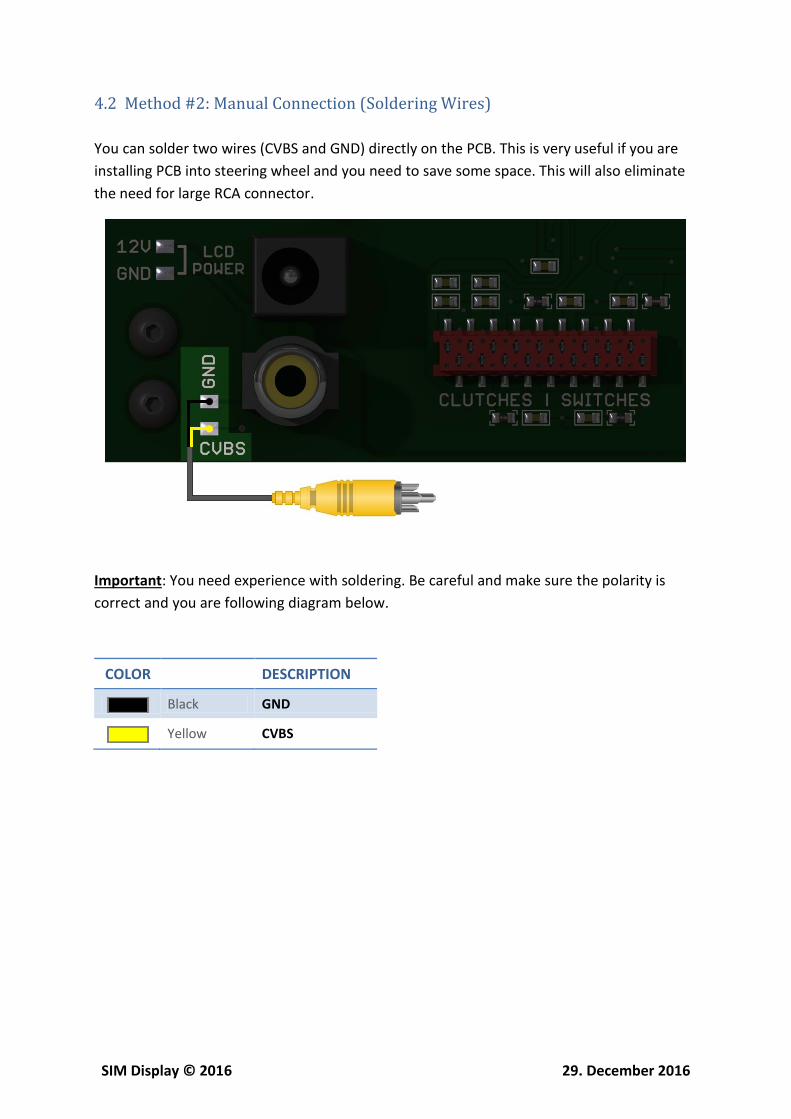
4.2 Method #2: Manual Connection (Soldering Wires)
You can solder two wires (CVBS and GND) directly on the PCB. This is very useful if you are
installing PCB into steering wheel and you need to save some space. This will also eliminate
the need for large RCA connector.
Important: You need experience with soldering. Be careful and make sure the polarity is
correct and you are following diagram below.
COLOR DESCRIPTION
Black GND
Yellow CVBS

SIM Display © 2016 29. December 2016
5 Pushbuttons
SIM Race LCD is a great solution for simracing because you can also use it as a racing
simulator and make button-box or steering wheel of your choice. There are two red (18-pin)
connectors on PCB dedicated for digital buttons and encoders.
All buttons will be recognized under WINDOWS OS (game controller panel) and can be used
in any game or simulation.
SIM Display © 2016 29. December 2016
6 Rotary Encoders
Encoders are very usefull to change settings in game quickly and precisely (like brake bias,
seat adjustment, brightness, etc). One encoder will be using one pair of (two) digital buttons.
Encoders are freely rotating devices (like potentiometers). Each rotation (detent) will press
button one time. Rotating encoder in one direction (clockwise) will press first button,
rotating it in other direction (anti clockwise) will press second button.
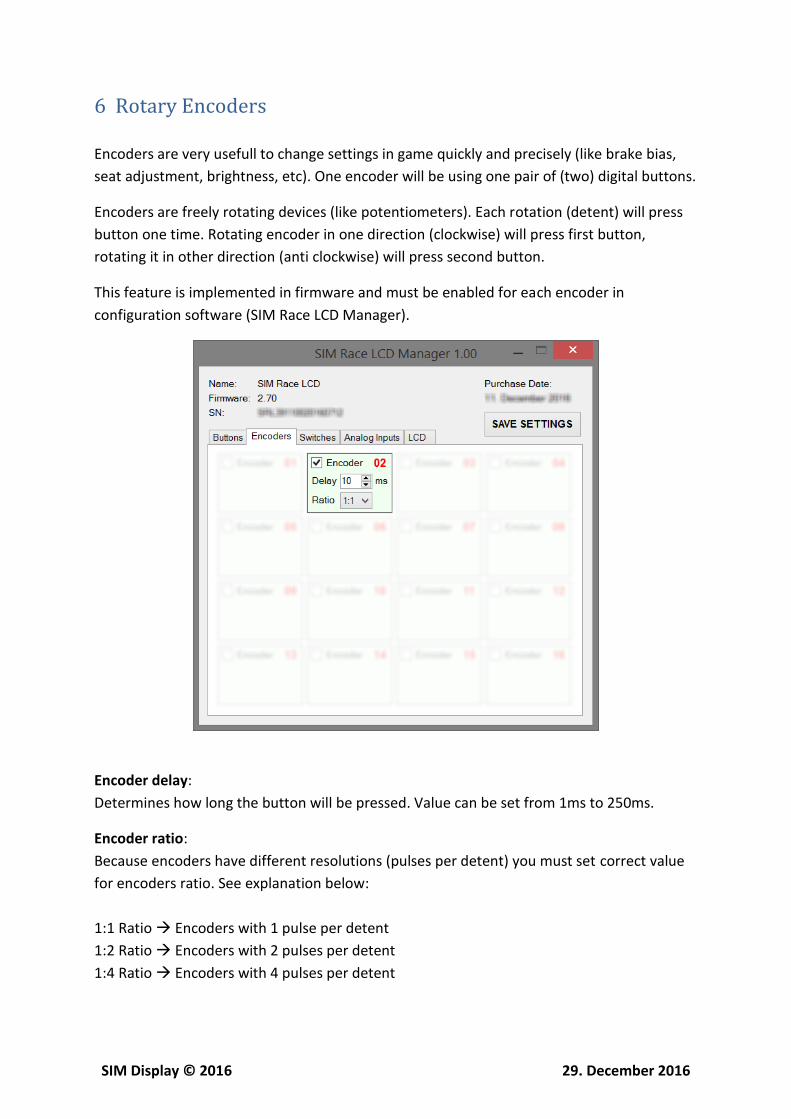
This feature is implemented in firmware and must be enabled for each encoder in
configuration software (SIM Race LCD Manager).
Encoder delay:
Determines how long the button will be pressed. Value can be set from 1ms to 250ms.
Encoder ratio:
Because encoders have different resolutions (pulses per detent) you must set correct value
for encoders ratio. See explanation below:
1:1 Ratio Encoders with 1 pulse per detent
1:2 Ratio Encoders with 2 pulses per detent
1:4 Ratio Encoders with 4 pulses per detent
SIM Display © 2016 29. December 2016
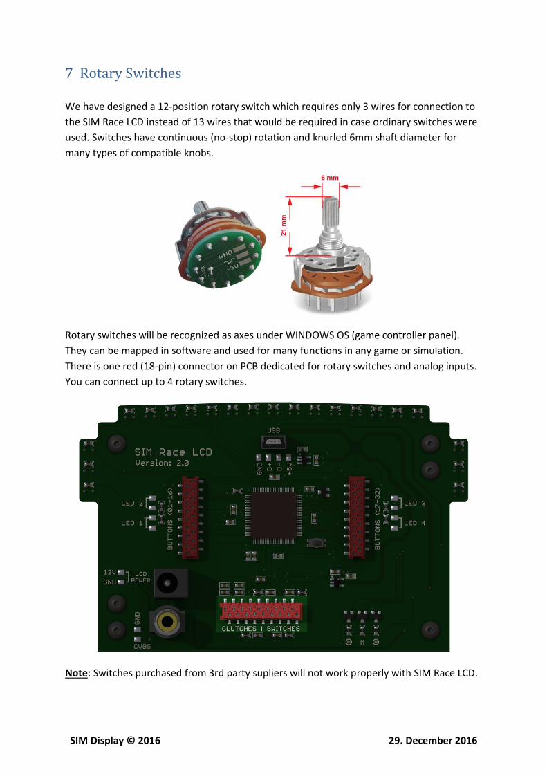
7 Rotary Switches
We have designed a 12-position rotary switch which requires only 3 wires for connection to
the SIM Race LCD instead of 13 wires that would be required in case ordinary switches were
used. Switches have continuous (no-stop) rotation and knurled 6mm shaft diameter for
many types of compatible knobs.
Rotary switches will be recognized as axes under WINDOWS OS (game controller panel).
They can be mapped in software and used for many functions in any game or simulation.
There is one red (18-pin) connector on PCB dedicated for rotary switches and analog inputs.
You can connect up to 4 rotary switches.
Note: Switches purchased from 3rd party supliers will not work properly with SIM Race LCD.

SIM Display © 2016 29. December 2016
8 Analog Inputs
SIM Race LCD features two (2) analog inputs with true 12-bit resolution (4096 steps).
Resolution can be reduced to 11-bit (2048 steps) or 10-bit (1024 steps) if high precision is
not required. Resolution can be changed in configuration software (SIM Race LCD Manager).
8.1 Analog Input Options
Disabled: If analog inputs are not used, they should be disabled.
Realistic F1 Clutch Behavior (BPF): Analog inputs are combined (dual mode).
Normal mode: Analog inputs are separated (single mode).
8.2 Analog Input Requirements
Maximum voltage: 3.3V
Maximum impedance: 2kΩ (recommended 1kΩ)
SIM Display © 2016 29. December 2016
9 Realistic F1 Clutch Behavior (BPF)
This is a special and unique feature implemented in our firmware only. It allows you to use
analog clutches in a way the real F1 car does. This will make a perfect start and quicker
getaway when red lights go out.
Since launch control was banned, it is now down to the driver to play with the clutch and
throttle to gain the perfect start. Driver must now manually perform the entire launch
sequence using hand operated clutches mounted to the back of steering wheel.
If you want to use this feature, you must first select »Realistic F1 Clutch Behavior (BPF)« in
configuration software and connect two separate clutches on each analog input. You can
either choose a solution with potentiometers or hall sensors.
9.1 How Does It Work
Both clutches do exactly the same thing but the standard practice in F1 today is to pre-set
one clutch position before fully engaging the other clutch. When red lights go out, release as
quickly as you can the first clutch and the car will start moving. As soon as you pick enough
traction, quickly release the second clutch and control your car with a throttle.
9.2 BPF Value Setup (SLIMax Manager Pro)
1) Set »display_clutch_biting_point_state« to true
2) Assign a button for BPF procedure: »btn_clutch_biting_point_finder«
3) Assign an axe used for the clutch: »sw_clutch_rpm«
4) Go on flat part of the track and make sure Auto Clutch is disabled in game
5) Fully engage (press) both clutch paddles
6) Engage gear 1
7) Press and release previously assigned button to start BPF detection
8) Accelerate then slowly release one clutch paddle until car moves
9) BPF value is now saved in software
Note: BPF value will be displayed only if »display_clutch_biting_point_state« is set to true.
Note: You can change and tune the BPF value later with rotary encoder.

SIM Display © 2016 29. December 2016
10 Wiring Diagram Examples
10.1 Pushbutton
Below is a wiring diagram how to connect button #19.
Note: All buttons share the same GND wire.
SIM Display © 2016 29. December 2016
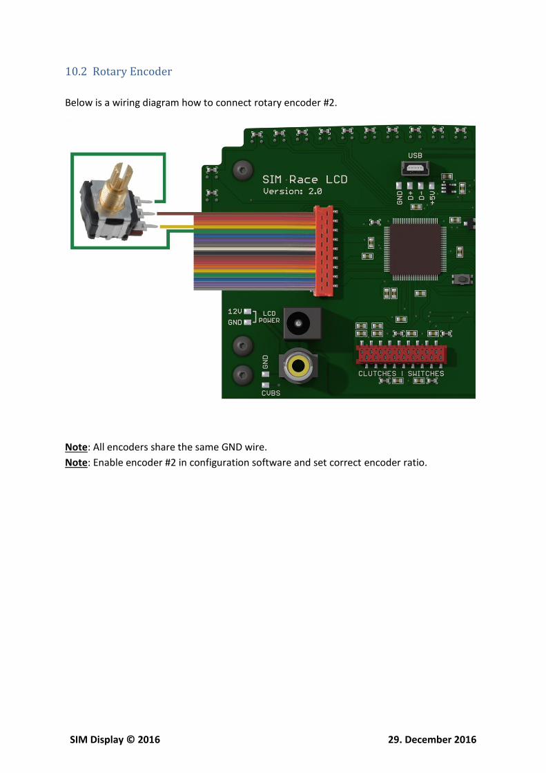
10.2 Rotary Encoder
Below is a wiring diagram how to connect rotary encoder #2.
Note: All encoders share the same GND wire.
Note: Enable encoder #2 in configuration software and set correct encoder ratio.
SIM Display © 2016 29. December 2016
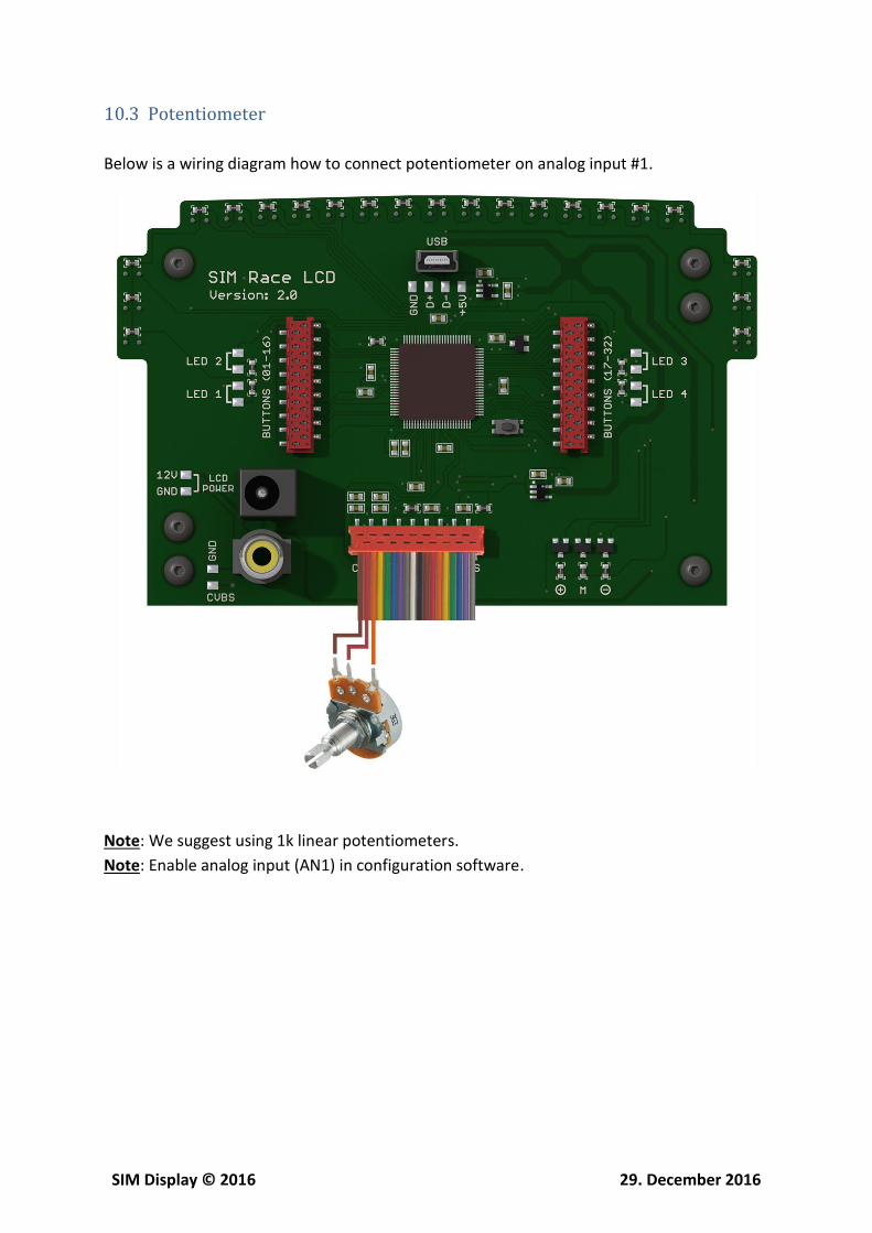
10.3 Potentiometer
Below is a wiring diagram how to connect potentiometer on analog input #1.
Note: We suggest using 1k linear potentiometers.
Note: Enable analog input (AN1) in configuration software.
SIM Display © 2016 29. December 2016
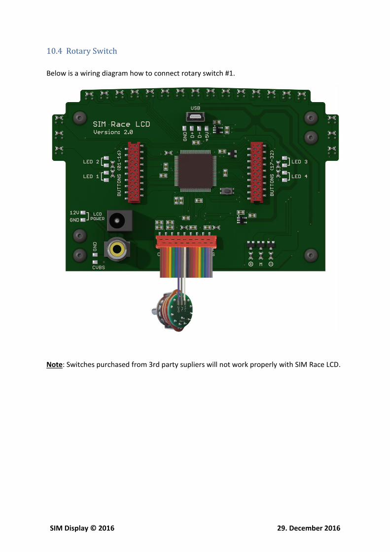
10.4 Rotary Switch
Below is a wiring diagram how to connect rotary switch #1.
Note: Switches purchased from 3rd party supliers will not work properly with SIM Race LCD.
SIM Display © 2016 29. December 2016
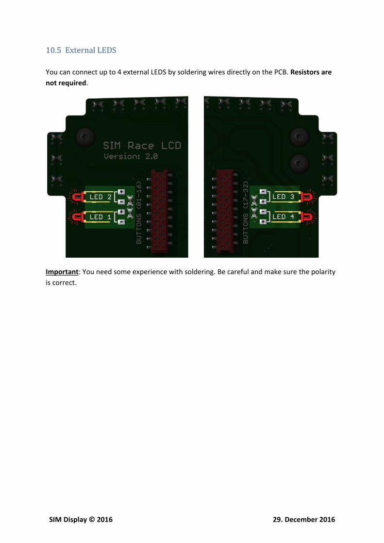
10.5 External LEDS
You can connect up to 4 external LEDS by soldering wires directly on the PCB. Resistors are
not required.
Important: You need some experience with soldering. Be careful and make sure the polarity
is correct.
SIM Display © 2016 29. December 2016
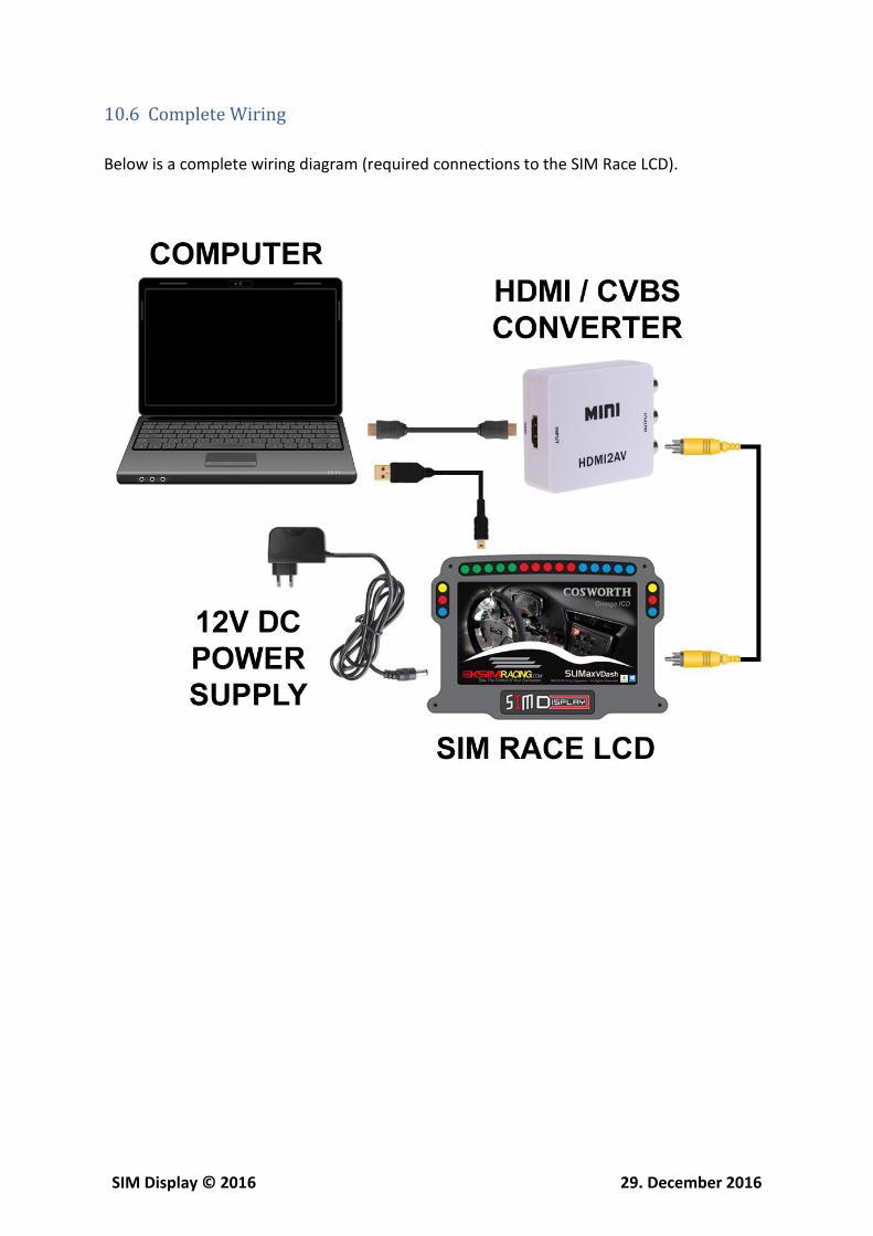
10.6 Complete Wiring
Below is a complete wiring diagram (required connections to the SIM Race LCD).

SIM Display © 2016 29. December 2016
11 Connector (BUTTONS 01-16)
PIN COLOR PRIMARY FUNCTION SECONDARY FUNCTION
1 Brown GND
2 Red Button 1 ROTARY ENCODER 1 3 Orange Button 2
4 Yellow Button 3 ROTARY ENCODER 2 5 Green Button 4
6 Blue Button 5 ROTARY ENCODER 3 7 Violet Button 6
8 Gray Button 7 ROTARY ENCODER 4 9 White Button 8
10 Black Button 9 ROTARY ENCODER 5 11 Brown Button 10
12 Red Button 11 ROTARY ENCODER 6 13 Orange Button 12
14 Yellow Button 13 ROTARY ENCODER 7 15 Green Button 14
16 Blue Button 15 ROTARY ENCODER 8 17 Violet Button 16
18 Gray GND

SIM Display © 2016 29. December 2016
12 Connector (BUTTONS 17-32)
PIN COLOR PRIMARY FUNCTION SECONDARY FUNCTION
1 Brown GND
2 Red Button 17 ROTARY ENCODER 9 3 Orange Button 18
4 Yellow Button 19 ROTARY ENCODER 10 5 Green Button 20
6 Blue Button 21 ROTARY ENCODER 11 7 Violet Button 22
8 Gray Button 23 ROTARY ENCODER 12 9 White Button 24
10 Black Button 25 ROTARY ENCODER 13 11 Brown Button 26
12 Red Button 27 ROTARY ENCODER 14 13 Orange Button 28
14 Yellow Button 29 ROTARY ENCODER 15 15 Green Button 30
16 Blue Button 31 ROTARY ENCODER 16 17 Violet Button 32
18 Gray GND

SIM Display © 2016 29. December 2016
13 Connector (CLUTCHES | SWITCHES)
PIN COLOR FUNCTION DESCRIPTION
1 Brown GND
ANALOG INPUT (AN1)
2 Red Analog Input 1
3 Orange +3.3V
4 Yellow GND
ANALOG INPUT (AN2)
5 Green Analog Input 2
6 Blue +3.3V
7 Violet GND ROTARY SWITCH
1 8 Gray Switch 1
9 White +3.3V
10 Black GND ROTARY SWITCH
2 11 Brown Switch 2
12 Red +3.3V
13 Orange GND ROTARY SWITCH
3 14 Yellow Switch 3
15 Green +3.3V
16 Blue GND ROTARY SWITCH
4 17 Violet Switch 4
18 Gray +3.3V