Embed Size (px)
Citation preview

SIM800
INTRODUCTION
SIM800 is a complete Quad-band GSM/GPRS solution in a SMT type
which can be embedded in the customer applications.SIM800 support Quad-
band 850/900/1800/1900MHz, it can transmit Voice, SMS and data information
with low power consumption. With tiny size of 24*24*3mm, it can fit into slim
and compact demands of customer design. Featuring Bluetooth and Embedded
AT, it allows total cost savings and fast time-to-market for customer
applications.
KEY FEATURES
AT command interface
Quad-band and Dual-band variants*
Make and receive voice calls
Send and receive SMS messages
Send and receive GPRS data (TCP/IP, HTTP, etc.)
Bluetooth: compliant with 3.0+EDR*
USB Connector for Firmware Updating*
Configurable Baud rate (9600-115200, factory default value: 9600)
Connectors for external speaker and mic.
Selectable interface between hardware serial port and software serial port
Inbuilt Powerful TCP/IP protocol stack for Internet data transfer over
GPRS.
Level shifting circuitry to make it Arduino-safe
SMA Connector with external antenna

Indicator LEDs for Power and connectivity
Standard Flap type SMA Socket
ESD Protection over TVS Zener array
Separate Reset switches for both Arduino and the shield
Slide switch to swap the shield between Arduino and PC
Provision to select between hardware and software serial ports
LED INDICATIONS
The Network LED indicates the various status of GSM module eg.
Power on, Network registration & GPRS connectivity. When the modem is
powered up, this NETWORK LED will blink every second. After the Modem
registers in the network (takes between 10-60 seconds), this LED will blink in
step of 3 seconds. At this stage you can start using Modem for your application,
showing that modem is registered with the network.
LED POWER STATE INDICATOR
POWER
LED
ON POWERED
STS LED ON READY TO
FUNCTION
NET LED
Blinking 1-sec Once YET TO FIND THE
NETWORK
Blinking 3-sec Once FOUND THE
NETWORK
Blinking 3-sec Once GPRS
COMMUNICATION

PIN DETAILS
IMAGE OF IOT MODEM
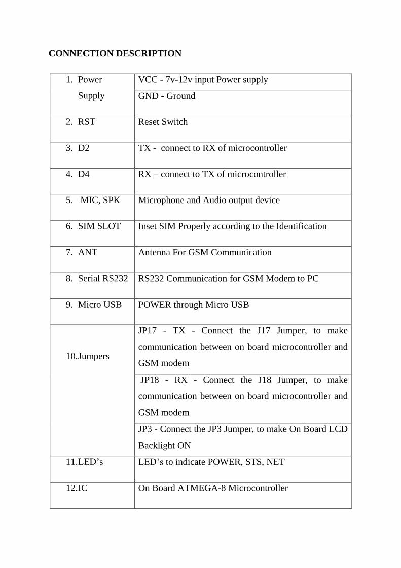
CONNECTION DESCRIPTION
1. Power
Supply
VCC - 7v-12v input Power supply
GND - Ground
2. RST Reset Switch
3. D2 TX - connect to RX of microcontroller
4. D4 RX – connect to TX of microcontroller
5. MIC, SPK Microphone and Audio output device
6. SIM SLOT Inset SIM Properly according to the Identification
7. ANT Antenna For GSM Communication
8. Serial RS232 RS232 Communication for GSM Modem to PC
9. Micro USB POWER through Micro USB
10. Jumpers
JP17 - TX - Connect the J17 Jumper, to make
communication between on board microcontroller and
GSM modem
JP18 - RX - Connect the J18 Jumper, to make
communication between on board microcontroller and
GSM modem
JP3 - Connect the JP3 Jumper, to make On Board LCD
Backlight ON
11. LED’s LED’s to indicate POWER, STS, NET
12. IC On Board ATMEGA-8 Microcontroller

13. TTL TTL Serial Communication for GSM Modem to PC
14. IC 5v Regulator IC
15. GSM SIM800A GSM Module
16. MAX232 IC Serial Communicate
JUMPER SETTING
JP3 Connect the JP3 Jumper, to make On Board LCD Backlight ON
JP17
TX - Connect the J17 Jumper, to make communication between on
board microcontroller and GSM modem
TX – Disconnect the J17 Jumper, to make use of only as a
Microcontroller Board or only as GSM Board
JP18
RX - Connect the J17 Jumper, to make communication between on
board microcontroller and GSM modem
RX – Disconnect the J17 Jumper, to make use of only as a
Microcontroller Board or only as GSM Board
REFERENCE CIRCUIT
Breakout Board SIM800A IOT Modem GND
D2 D4
Microcontroller GND TX RX

SET BAUD AND ENABLE CHARGING FUNCTION
It is recommended to execute this process when first time to use the module. In
the Serial Monitor columns of following tables, input of AT commands is in
back, module returns values are in orange.
Serial Monitor Description
AT
OK
Send command “AT” to synchronize baud rate. Serial
port of module is by default set at auto-baud mode, and in
this mode, it will not output any indications when the
module is on.
AT+IPR=9600
OK
Set baud rate at 9600bps, supports baud rate from
1200bps to 115200bps.
AT+ECHARGE=1
OK
Send command “AT+ECHARGE=1” to enable battery
charging function. By default the charging function is
closed.
AT&W
OK Save parameter setting.
AT+CPOWD=1
NORMAL POWER
DOWN
Power down the module.

RDY
+CFUN: 1
GPS Ready
+CPIN: READY
Call Ready
SMS Ready
Turn on the module again by the power button, it will
response status about GPS and GSM.
AT+CBC
+CBC: 1,96,4175
OK
Inquire charging status and remaining battery capacity.
AT+CSQ
+CSQ: 14,0
OK
Inquire GSM signal quality.
COMMUNICATION BETWEEN MODEM AND PC
Serial Monitor Description
$
ENTER THE MAIN URL
http://WWW.________.______/>:
Send “$”symbol
to synchronize
baud rate (9600).
myiotproject.com
ENTERED URL IS myiotproject.com. 1. OK 2. REENTER
Send Website
address.

1 or 2
ENTER THE USER ID:
1 for you typed
website address
is ok, 2- for
reenter the
website address.
USER1
ENTERED URL IS USER1. 1. OK 2. REENTER
Enter the website
user ID
1 or 2
ENTER THE NO.OF VARIABLES (min 1) (max 9)
1 for you typed
website user ID
is ok, 2- for
reenter the
website user ID
.
1 to 9 (Any Number as per user need) e.g: if I entered 2
YOU SHOULD SEND 2 VALUE.
1. OK 2. REENTER
Send 1 to 9
different
variables i.e
You can send 9
different sensor
values
1 or 2
ENTER THE VALUE 1 URL e.g:<temp> 5 char max:
1 for you
variable number
is ok, 2- for
reenter the

variable number
TEMP
Entered Variable name is TEMP 1. OK 2. REENTER
Set the 1st
variable name
(max-Character
is 5)
1 or 2
ENTER THE VALUE 2 URL e.g:<temp> 5 char max:
1 for you
variable name is
ok, 2- for reenter
the variable
name
GAS
Entered Variable name is GAS 1. OK 2. REENTER
Set the 2nd
variable name
(max-Character
is 5)
1 or 2
THE SAMPLE URL IS .
http://www.myiotproject.com?usee=”USER1”&TEMP==---
/"
1 for you
variable name is
ok, 2- for reenter
the variable
name
~
TEMP
Send “~”
symbol to Send
Sensor Value

Website
You will Get
“Temp” from
website
(You will get
variable name
according to
that you have to
send data )
Send Temperature Value
GAS
Now Send
Temp Value
You will Get
“GAS” from
website
Send GAS Value
Now Send
Temp Value

TERMINAL OUTPUT

WEBSITE OUTPUT WINDOW