Embed Size (px)
Citation preview

Important Note
This supplement contains important information. The statements made take precedence over those in the operating instructions and online help.
Please read this supplement carefully, it contains helpful information.
SIMATIC HMI Panel PC Ex Thin Client Ex
Notes
Supplement to operating instructions
Edition 02/2013
This supplement is valid for products with following order numbers:
SIMATIC HMI Panel PC Ex 6AV7200-1…
SIMATIC HMI Thin Client Ex 6AV7200-0…

Supplement to operating instructions Edition 02/2013
2/52 A5E02338654-01
Please follow the guidelines mentioned in the manual! Safety Guidelines Safety Guidelines This manual contains notices you have to observe in order to ensure your personal safety, as well as to prevent damage to property. Qualified Personnel The device/system may only be set up and used in conjunction with this documentation. Commissioning and operation of a device/system may only be performed by qualified personnel. Within the context of the safety notes in this documentation qualified persons are defined as persons who are authorized to commission, ground and label devices, systems and circuits in accordance with established safety practices and standards. Prescribed Usage Note the following: WARNING This device may only be used for the applications described in the catalog or the technical description and only in connection with devices or components from other manufacturers which have been approved or recommended by Siemens. Correct, reliable operation of the product requires proper transport, storage, positioning and assembly as well as careful operation and maintenance. Trademarks The trademarks in this publication may be trademarks whose use by third parties for their own purposes could violate the rights of the owner. Disclaimer of Liability We have reviewed the contents of this publication to ensure consistency with the hardware and software described. Since variance cannot be precluded entirely, we cannot guarantee full consistency. However, the information in this publication is reviewed regularly and any necessary corrections are included in subsequent editions.

Supplement to operating instructions Edition 02/2013
3/52 A5E02338654-01
Service and support Local information
If you have questions about the products described in this document, you can find help at: http://www.siemens.com/automation/partner
Technical documentation for SIMATIC products
Further documentation for SIMATIC products and systems can be found at: http://www.siemens.com/simatic-tech-doku-portal
Easy Shopping at the Mall
Catalog & online ordering system http://www.siemens.com/automation/mall Training
All the training options are listed at: http://www.siemens.com/sitrain Find a contact at: Phone: +49(911) 895-3200
Technical support
Tel +49 (0)911 895 7222 Fax +49 (0)911 895 7223 http://www.siemens.com/automation/csi/service A Web form for Support Request can be found at: http://www.siemens.com/automation/support-request When you contact the customer support, please have the following information for the technician on hand: ● BIOS version ● Order No. (MLFB) of the device ● Installed additional software ● Installed additional hardware
Online support
Information about the product, Support and Service, right through to the Technical Forum, can be found at: http://www.siemens.com/automation/service&support
After-sales information system for SIMATIC PC / PG
Information about contacts, drivers, and BIOS updates, FAQs and Customer Support can be found at: http://www.siemens.com/asis

Supplement to operating instructions Edition 02/2013
4/52 A5E02338654-01
Notice to device designation Panel PC Ex devices The table below lists the Panel PC Ex devices together with their marking on the type plate and the Operating Instructions.
MLFB Designation Siemens Device designation (includes)
6AV720 0-1abcdx a = A Panel PC Ex, Zone 2, 15“ MT-436-A-xx-TFT-xx
a = B Panel PC Ex, Zone 2, 19“ MT-456-A-xx-TFT-xx
a = D Panel PC Ex, Zone 1, 15“ ET-436-A-xx-TFT-xx
a = E Panel PC Ex, Zone 1, 19“ ET-456-A-xx-TFT-xx
a = J Panel PC Ex, Zone 2, 15“, SR MT-436-A-xx-SR-xx
a = K Panel PC Ex, Zone 1, 15“, SR ET-436-A-xx-SR-xx
6AV720 0-1abcdx b = A 10/100Base-TX xx-4x6-A-TX-xx
b = B 100Base-FX xx-4x6-A-FX-xx
6AV720 0-1abcdx c = 1 CF 4GB, 1GB RAM c = 2 CF 16GB, 1GB RAM c = 3 HDD 100GB, 1GB RAM c = 4 CF 4GB, 2GB RAM c = 5 CF 16GB, 2GB RAM c = 6 HDD 100GB, 2GB RAM
xx-4x6-A-xx-R1-4GB-xx xx-4x6-A-xx-R1-16GB-xx xx-4x6-A-xx-R1-100GB-xx xx-4x6-A-xx-R2-4GB-xx xx-4x6-A-xx-R2-16GB-xx xx-4x6-A-xx-R2-100GB-xx
6AV720 0-1abcdx d = 1 Windows XPe d = 3 Windows XP Pro d = 4 Windows 7 Ultimate
xx-4x6-A-xx-XPe xx-4x6-A-xx-XPp xx-4x6-A-xx-7U
6AV7675-0PX00-0AA0 Ethernet Switch SK-KJ1740
The language sets of Windows XP Embedded contains the following languages: Windows XPe set 1
English
German
French
Italian
Spanish
Portugese / Portugal
Portugese / Brazil
Dutch
Danish
Swedish
Norwegian
Finnish
Greek
Hungarian
Czech
Polish
Russian
Turkish
Hebrew (right-to-left layout)
Arabic (right-to-left layout)
Chinese (Traditional)
Chinese (Simplified)
Japanese
Korean

Notice to device designation Thin Client Ex devices The table below lists the Thin Client Ex devices together with their marking on the type plate and the Operating Instructions.
MLFB Designation Siemens Device designation (includes)
6AV720 0-0ab00xx a = A Thin Client Ex, Zone 2, 15“ MT-536-A-xx-TFT-xx
a = B Thin Client Ex, Zone 2, 19“ MT-556-A-xx-TFT-xx
a = D Thin Client Ex, Zone 1, 15“ ET-536-A-xx-TFT-xx
a = E Thin Client Ex, Zone 1, 19“ ET-556-A-xx-TFT-xx
a = G Thin Client Ex, Zone 2, 15“, SR MT-536-A-xx-SR-xx
a = H Thin Client Ex, Zone 1, 15“, SR ET-536-A-xx-SR-xx
6AV720 0-0ab00xx b = A 10/100Base-TX xx-5x6-A-TX-xx
b = B 100Base-FX xx-5x6-A-FX-xx
6AV7675-0EX00-0AA0 Digital KVM-Box 5x6-KVM-digital
6AV7675-0PX00-0AA0 Ethernet Switch SK-KJ1740

Supplement to operating instructions Edition 02/2013
6/52 A5E02338654-01
Note on device combinations If a Panel PC Ex / Thin Client Ex device is installed inside a control cabinet or an enclosure together with an additional heater, please note the special conditions that apply with regard to the minimum temperature. In general, the entire combination of devices is certified for a temperature range of -30°C to +40°C. If the temperature of the entire unit falls BELOW –20°C the Panel PC Ex / Thin Client Ex device may only be switched on once the temperature has been raised back to -20°C or above. This must be ensured by means of monitoring the temperature inside the control cabinet or enclosure. Alternatively, this can be ensured by pre-heating the unit with a type TEF 9201 100 W heater for one and a half hours.
For the correct operation of all associated components please note, in addition to these operating instructions, all other operating instructions enclosed in this delivery as well as the operating instructions of the additional equipment to be connected.
Panel PC Ex Thin Client Ex
heater (z.B. TEF 9201)
-20°C … +40°C
-30°C … +40°C
-30°C … +40°C

Operating Instructions
ET-xx6-A
Series 400 Panel PC
Series 500 Thin Clients
(valid for HW Revision 3)
HW-Rev. ET-xx6-A-Fx: 03.00.11 HW-Rev. ET-xx6-A-Tx: 03.00.21 Operating Instructions Version: 03.00.01 Issue date: 12.02.2013

Operating Instructions ET-xx6-A Table of contents
Page 8 of 52 OI_ET_xx6_A_SIE_en_V_03_00_01.docx / 12.02.2013
Table of contents
Description Page
Table of contents 8
1 Preface 10
2 Device function 10
2.1 ET-4x6-A (Series 400 Panel PC) 10
2.2 ET-5x6-A (Series 500 Thin Clients) 10
3 Technical Data 11
3.1 Additionally for ET-4x6-A (Panel PC) 12
4 Conformity to standards 13
5 Certificates 13
5.1 ATEX 13
5.2 IECEx 13
5.3 DNV 14
5.4 LR 14
5.5 GOST-R 14
5.6 CSA 14
5.7 KGS 14
5.8 UL-BR 14
6 Marking 15
7 Power supply 16
7.1 Operator interfaces 16
7.1.1 Operator interface terminals 16
7.1.1.1 Tightening torque 16
8 Permitted maximum values 16
8.1 External, non-intrinsically safe circuits 16
8.2 External inherently safe optical interface 17
8.3 External intrinsically safe circuits 17
9 Type code 19
9.1 ET-4x6-A (Panel PC) 19
9.2 ET-5x6-A (Thin Client) 20
10 Safety Advice 21
10.1 Installation and operation 21
10.2 Cautionary note 22
10.3 Special conditions 22
11 Installation 22
11.1 General information 22
11.2 ET-xx6-A 22
11.3 Installation via USB-interfaces 23
11.3.1 Software installation using a USB Memory Stick 23
11.3.2 Software installation with external USB devices 23
11.4 USB interfaces 24
11.4.1 I.S. USB interfaces USB0, USB2 24
11.4.2 Ex-e USB interfaces USB1, USB3 24
11.4.2.1 Connection variations for Ex-e USB interfaces 24
11.4.2.2 Connection terminal with protection type "e" (EN 60079-7) 25

Operating Instructions ET-xx6-A Table of contents
OI_ET_xx6_A_SIE_en_V_03_00_01.docx / 12.02.2013 Page 9 of 52
12 Assembly and disassembly 27
12.1 General information 27
12.2 Cut-out ET-xx6-A 27
13 Operation 27
13.1 General information 27
13.2 Connections 28
13.2.1 Dip switch settings S3 and S4 29
13.2.2 Status LEDs 30
13.2.2.1 LEDs 30
14 Exicom-SHD-xxx hard disk 32
14.1 Installation of hard disk 32
14.1.1 Mechanical dimensions 32
14.2 Connections 33
14.2.1 Safety advice 33
14.3 Hard disk replacement 33
15 Maintenance, service 34
15.1 Servicing 34
15.2 Time function 34
16 Troubleshooting 35
17 Disposal 35
17.1.1 ROHS directive 2002/95/EC 35
17.1.2 China ROHS labelling 35
18 Front panel resistance 36
18.1 Design 36
18.2 Materials 36
18.3 Material properties 36
18.3.1 Entire device 37
18.3.2 Membrane top (Polyester) 37
18.3.3 Touch screen 39
18.3.4 Front panel seal 40
19 General Information 41
19.1 Keyboard features 41
19.2 ET-4x6-A (Panel PC) 42
19.2.1 Licensing issues 42
19.2.2 Recovery Stick 42
19.2.3 Back-up 42
19.2.4 Initial start-up 42
19.2.4.1 Initial start-up XP Pro/WIN 7 42
19.2.4.2 Initial start-up XP Embedded 42
19.2.5 Switching off/closing down 43
19.2.5.1 Note on XP Embedded 43
19.2.6 Installation Windows XP Professional 44
20 CSA Control Drawing 45
21 Declaration of EC conformity 48
22 Release notes 49

Operating Instructions ET-xx6-A Preface
Page 10 of 52 OI_ET_xx6_A_SIE_en_V_03_00_01.docx / 12.02.2013
1 Preface
These Operating Instructions contain all aspects relevant to explosion protection for the ET-xx6-A operator interfaces (series 400 Panel PC and series 500 Thin Clients). They also contain information on the connection and installation of these devices. Please also refer to additional documentation included in the delivery, such as the examination certificate and the hardware manual, which contain further important information. These operating instructions contain a joint description of product lines Panel PC and Thin Client. Any differences between these product lines will be explicitly mentioned and dealt with. As a rule, though, the information contained in these operating instructions applies to all models of the ET-xx6-A series. The ET-xx6-A operator interfaces with display sizes of 26 cm/10.4", 38 cm/15" and 48 cm/19" will be available in Hardware Revision 3.
For the correct operation of all associated components please note, in addition to these operating instructions, all other operating instructions enclosed in this delivery as well as the operating instructions of the additional equipment to be connected.
Please also note that all certificates of the operator interfaces can be found in a separate document !
2 Device function
The ET-xx6-A operator interfaces are explosion-proof equipment for installation in hazardous areas and can be installed in zones 1, 2, 21 and 22 according to ATEX directive 94/9/EC. All devices have a modular structure, which makes changes and maintenance easy. They can be integrated into control cabinets or panels, etc.
2.1 ET-4x6-A (Series 400 Panel PC)
The ET-4x6-A Panel PC Ex devices are robust Panel PCs for hazardous areas. With their pre-installed Windows operating systems they are ready to run straight away. As a standard, all Panel PCs are equipped with a touch screen and several interfaces and are based on the powerful ATOM technology (1.6 GHz clock frequency), making them the most powerful devices on the market.
2.2 ET-5x6-A (Series 500 Thin Clients)
The ET-5x6-A devices of the 500 series can be integrated into modern networks as Thin Clients or with a KVM box via KVM-over-IP, thus providing ideal and flexible access options with central data administration. The ET-5x6-A operator interfaces, which are used for operation and visualization, are located in the hazardous area, whereas the PC that is operated is located in the safe area. Each ERP/MES network can be accessed from each Thin Client via the IP address. The Thin Client system supports both modern technologies such as DVI and USB and older technologies such as VGA and PS/2.

Operating Instructions ET-xx6-A Technical Data
OI_ET_xx6_A_SIE_en_V_03_00_01.docx / 12.02.2013 Page 11 of 52
3 Technical Data
Function / Equipment ET-406-A ET-416-A ET-436-A-(SR) ET-536-A-(SR)
ET-456-A ET-556-A
Display type TFT Color,
16,777,216 Colors
Display size 26 cm (10.4") 38 cm (15") 48 cm (19")
Resolution in pixels SVGA 800 x 600 XGA 1024 x 768 SXGA 1280 x 1024
Display Touch screen on glass
Touch Screen
normal 8-wire analogue resistive
Sunlight readable - 5-wire analogue resistive
-
Backlight LED background lighting
Service life of backlight
at +10°C 130,000 h 500,000 h 50,000 h
at +35°C 55,000 h 70,000 h -
at +55°C 40,000 h 50,000 h -
Brightness
normal 400 cd/m² 350 cd/m² 350 cd/m²
Sunlight readable - 1000 cd/m² -
Contrast
normal 700:1 1000:1
Sunlight readable - 600:1 -
Keyboard Polyester membrane on aluminium plate (> 1 million actions)
Functional keys
Soft keys
Cursor keys
Alphanumeric keys
System keys
12
10
Yes
12
14
12
no
no
no
no
8
no
no
no
no
8
no
no
no
no
Additional keyboard
optional 100 mA max. power consumption
105 Keys
or
107 keys with integrated trackball / joystick
Trackball/Joystick optional
Power supply Directly in the integrated Ex-e connection box
Connections via screw terminals, 2.5 mm² green (Ex-e)
Power supply 24 VDC (20.4 to 28.8 VDC)
Power consumption [A] 1.2 A
max. operating voltage Um 30 VDC
ET-xx6-A
Real-time clock Yes
Lithium battery and capacitor buffered, maintenance-free
> 5 years
at least 4 days
Data buffer
Battery
Capacitor
Status display LEDs
below the back cover
for activity on
- Solid state flash drive or HD
- Ethernet link
- COM 1 and COM 2
Interfaces
Ethernet Either Tx or Fx
Copper (Tx) 10/100BaseTx, 10/100 Mbit (Ex-e)
Optical fibre (Fx) 100BaseFx, 100 Mbit, inherently safe (Ex op is)
USB 2x Ex-e; 2x Ex-i
PS/2 (Ex-i) For external keyboard, mouse, trackball, joystick
Serial COM1 RS-232, RS-422, RS-485 (Ex-e)
Fieldbus not for Thin Client
Panel PC MPI with MPI Box SSW7-HMI-RS-422
Audio Line Out output (Ex-e)
Data cable/-lenght
Copper (Tx) up to 100 m via CAT5 installation cable AWG22
Optical fibre (Fx) up to 2000 m via 62,5/125 μm (core-/external cross section) multi-mode optical fibre cable

Operating Instructions ET-xx6-A Technical Data
Page 12 of 52 OI_ET_xx6_A_SIE_en_V_03_00_01.docx / 12.02.2013
Function / Equipment ET-406-A ET-416-A ET-436-A-(SR) ET-536-A-(SR)
ET-456-A ET-556-A
Front plate Polyester on seawater-proof aluminium with touch technology and safety glass
Housing Stainless steel
Housing protection type IP 66
Operating temperature range
Operation - 20°C … + 55°C*
Operation with heater * - 30°C … + 55°C*
Operation with heater**, housing insulation and protective screen
- 40°C … + 55°C*
Storage temperature range - 30°C … + 60°C
* Comment for ET-4x6-A and ET-5x6-A:
operation at +55°C for a maximum of 5 hours, at +50°C for continuous operation (24/7)
** Comment ** The heater used must be of such a design that the temperature inside the operator interface's housing does not fall below -20°C (-30°C only at the front) !
Heat dissipation approx. 50 % via front plate, approx. 50 % via housing
Relative humidity 90% at + 40 °C, without condensation
Vibration
Operation 3 to 22 Hz: 1 mm
22 to 500 Hz: 9.8 m/s² = 1 g
Transport: 3 to 9 Hz: 3.5 mm
9 to 500 Hz: 9.8 m/s² = 1 g
Shock loading
Operation 150 m/s² = about 15 g / 11 ms
Transport: 250 m/s² = about 25 g / 6 ms
Dimensions [mm]
Front (w x h) 400 x 270 372 x 270 440 x 340 535 x 425
Cut-out w x h [mm] (+/- 0.5)
385.5 x 257.5 359.5 x 257.5 427.5 x 327.5 522.5 x 412.5
Depth of cut-out 150 165
Wall thickness ≤ 8
Mounting position vertical or horizontal
Weight [kg]
Device 13.00 12.60 17.30 23.5
Fixing frame 0.6 0.6 0.7 0.9
3.1 Additionally for ET-4x6-A (Panel PC)
Processor ATOM 1.6 GHz
Working memory [GB]
Data memory [GB]
1 or 2
4 or 16
Type of data memory
Standard Solid state flash drive
Optional expansion to Exicom-SHD-xxx hard disk
100 GB
instead of flash drive
Operating system Windows XP Embedded
Windows XP Professional
Windows 7 Ultimate
Standard Software WIN CC flexible
Global language support Via Multi-Language interface of Windows XP embedded (25 languages)
Operating Instructions ET-xx6-A Conformity to standards
OI_ET_xx6_A_SIE_en_V_03_00_01.docx / 12.02.2013 Page 13 of 52
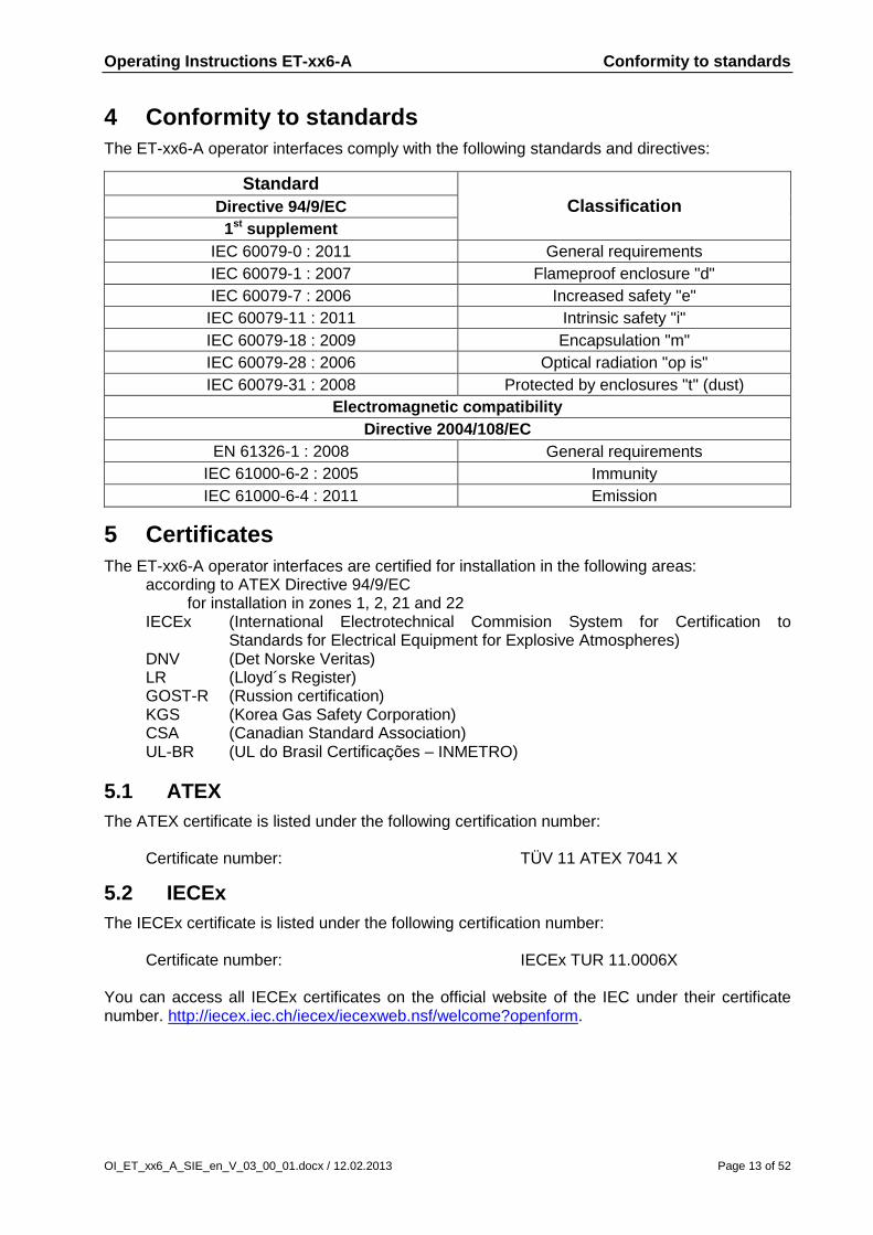
4 Conformity to standards
The ET-xx6-A operator interfaces comply with the following standards and directives:
Standard
Classification Directive 94/9/EC
1st supplement
IEC 60079-0 : 2011 General requirements
IEC 60079-1 : 2007 Flameproof enclosure "d"
IEC 60079-7 : 2006 Increased safety "e"
IEC 60079-11 : 2011 Intrinsic safety "i"
IEC 60079-18 : 2009 Encapsulation "m"
IEC 60079-28 : 2006 Optical radiation "op is"
IEC 60079-31 : 2008 Protected by enclosures "t" (dust)
Electromagnetic compatibility
Directive 2004/108/EC
EN 61326-1 : 2008 General requirements
IEC 61000-6-2 : 2005 Immunity
IEC 61000-6-4 : 2011 Emission
5 Certificates
The ET-xx6-A operator interfaces are certified for installation in the following areas: according to ATEX Directive 94/9/EC for installation in zones 1, 2, 21 and 22 IECEx (International Electrotechnical Commision System for Certification to
Standards for Electrical Equipment for Explosive Atmospheres) DNV (Det Norske Veritas) LR (Lloyd´s Register) GOST-R (Russion certification) KGS (Korea Gas Safety Corporation) CSA (Canadian Standard Association) UL-BR (UL do Brasil Certificações – INMETRO)
5.1 ATEX
The ATEX certificate is listed under the following certification number: Certificate number: TÜV 11 ATEX 7041 X
5.2 IECEx
The IECEx certificate is listed under the following certification number: Certificate number: IECEx TUR 11.0006X You can access all IECEx certificates on the official website of the IEC under their certificate number. http://iecex.iec.ch/iecex/iecexweb.nsf/welcome?openform.

Operating Instructions ET-xx6-A Certificates
Page 14 of 52 OI_ET_xx6_A_SIE_en_V_03_00_01.docx / 12.02.2013
5.3 DNV
The DNV certification is listed below the following numbers:
Certificate number: A-12989 File number: 899.60 Job Id: 262.1-001689-6
5.4 LR
The LR (Lloyd´s Register) certificate is listed under the following certification number:
Certificate number: 11/20032
5.5 GOST-R
The GOST-R certification is listed below the following number:
Certificate number: РОСС DE.ГБ04.B01741
5.6 CSA
The CSA certificate is listed under the following certification number:
Certificate number: 2512677
5.7 KGS
The KGS certificate is listed under the following certification number:
Certificate number: 12-GA4BO-0215X and 12-GA4BO-0317X NB: In order to be able to operate these terminals in Korea, each device type additionally requires a KCC certificate. Please enquire at our Sales or Support departments which device types have already been issued with such a certificate.
5.8 UL-BR
The UL-BR certificate is listed under the following certification number:
Certificate number: UL-BR 12.0265X

Operating Instructions ET-xx6-A Marking
OI_ET_xx6_A_SIE_en_V_03_00_01.docx / 12.02.2013 Page 15 of 52
6 Marking
Manufacturer R. STAHL HMI Systems GmbH
Type code ET-4x6-A / ET-5x6-A
CE classification: c 0158
Testing authority and certificate number:
TÜV 11 ATEX 7041 X
IECEx TUR 11.0006X
Ex classification: e
ATEX directive 94/9/EC
ET-xx6-A-Tx II 2 (2) G Ex d e ia ib mb [ia ib] IIC T4 Gb
II 2 (2) D Ex ia tb [ia ib] IIIC T80°C Db IP66
ET-xx6-A-Fx e II 2 (2) G Ex d e ia ib mb [ia ib op is] IIC T4 Gb
II 2 (2) D Ex ia tb [ia ib op is] IIIC T80°C Db IP66
IECEx
ET-xx6-A-Tx Ex d e ia ib mb [ia ib] IIC T4 Gb
Ex ia tb [ia ib] IIIC T80°C Db IP66
ET-xx6-A-Fx Ex d e ia ib mb [ia ib op is] IIC T4 Gb
Ex ia tb [ia ib op is] IIIC T80°C Db IP66
GOST-R
ET-xx6-A-Tx 2Exdeiaibmb[iaib]IICT4
DIP A21 TA80°C, IP66
ET-xx6-A-Fx 2Exdeiaibmb[iaibopis]IICT4
DIP A21 TA80°C, IP66
CSA Ex d e ia ib mb [ia ib] IIC T4 Gb, Type 4X, IP66
Class II, Division 1, Groups E, F, G, T80°C
Ex ia tb [ia ib] IIIC T80°C Db, IP66
KGS Ex d e ia ib mb [ia ib]IIC T4
Ex ia tb [ia ib] IIIC T80°C Db IP66
UL-BR
ET-xx6-A-Tx Ex d e ia ib mb [ia ib] IIC T4 Gb
Ex ia tb [ia ib] IIIC T80°C Db IP66
ET-xx6-A-Fx Ex d e ia ib mb [ia ib op is] IIC T4 Gb
Ex ia tb [ia ib op is] IIIC T80°C Db IP66

Operating Instructions ET-xx6-A Power supply
Page 16 of 52 OI_ET_xx6_A_SIE_en_V_03_00_01.docx / 12.02.2013
7 Power supply
7.1 Operator interfaces
Power supply: 24.0 VDC (min. 20.4 VDC , max. 28.8 VDC) Power consumption: ET-xx6-A 1.2 A 7.1.1 Operator interface terminals
Copper wires with cross sections of betwee 0.2 mm² (AWG 24) and 1.5 mm² (AWG 14) may be connected to any of the terminals of the operator interfaces.
When connecting cables to the terminals please make sure that the insulation of the cables goes right up to the terminal contacts.
7.1.1.1 Tightening torque
For the terminals X1 and X11 a tightening torque of: 0,4 Nm up to 0,5 Nm is valid and for the terminals X2, X3, X4, X5, X6, X7, X8 and X9 a tightening torque of: 0,5 Nm bis 0,6 Nm is valid.
8 Permitted maximum values
8.1 External, non-intrinsically safe circuits
Input voltage (X1):
Rated voltage 24 VDC (+20% / -15%) Power consumption at Urated 1.2 A max max. working voltage Um 30 VDC
RS-422/-232 COM 1 (X2):
Rated voltage RS-422: 5 VDC RS-232: ±12 VDC Max. operating voltage Um 253 VAC
USB-1 (X5):
Rated voltage 5 VDC Max. operating voltage Um 253 VAC
USB-3 (X7):
Rated voltage 5 VDC Max. operating voltage Um 253 VAC
Copper Ethernet (X11):
Rated voltage 5 VDC Rated power 100 mW Max. operating voltage Um 30 VDC
Audio (X3):
Rated voltage 5 VDC Max. operating voltage Um 253 VAC

Operating Instructions ET-xx6-A Permitted maximum values
OI_ET_xx6_A_SIE_en_V_03_00_01.docx / 12.02.2013 Page 17 of 52
8.2 External inherently safe optical interface
Ethernet optical fiber (X10):
Wavelength 1350 nm Radiant power ≤ 35 mW
8.3 External intrinsically safe circuits
USB0 (X4):
The maximum values for group IIC are:
Ui = - V Uo = 5.9 V
Ii = - mA lo = 2.18 A
Pi = - mW Po = 1.24 W
Ci = 0 F Co = 5.1 11 28 43 F
Li = 0 mH Lo = 10 5 2 1 H
Co and Lo pairs directly above/underneath each other may be used. The maximum values for group IIB are:
Ui = - V Uo = 5.9 V
Ii = - mA lo = 2.18 A
Pi = - mW Po = 1.24 W
Ci = 0 F Co = 14 40 79 200 F
Li = 0 mH Lo = 50 20 10 5 H
Co and Lo pairs directly above/underneath each other may be used.
USB-2 (X6): The maximum values for group IIC are:
Ui = - V Uo = 5.9 V
Ii = - mA lo = 2.18 A
Pi = - mW Po = 1.24 W
Ci = 0 F Co = 5.1 11 28 43 F
Li = 0 mH Lo = 10 5 2 1 H
Co and Lo pairs directly above/underneath each other may be used. The maximum values for group IIB are:
Ui = - V Uo = 5.9 V
Ii = - mA lo = 2.18 A
Pi = - mW Po = 1.24 W
Ci = 0 F Co = 14 40 79 200 F
Li = 0 mH Lo = 50 20 10 5 H
Co and Lo pairs directly above/underneath each other may be used.

Operating Instructions ET-xx6-A Permitted maximum values
Page 18 of 52 OI_ET_xx6_A_SIE_en_V_03_00_01.docx / 12.02.2013
Reader RSi1 (X8) +Uint 1 (power supply circuit, X8.0, bridge to X8.2):
Uo = 10.4 V
lo = 220 mA
Po = 2.29 W
Co = 0.08 F
Lo = 0.01 mH
Reader RSi1 (X8) +U_ex1 (power supply circuit, X8.2, bridge from X8.0):
Ui = 12.4 V
Ii = 220 mA
Pi = 2.29 mW
Ci = 25 nF
Li = 0 mH
PS2 interface (X9):
Connection for keyboard, mouse, trackball, joystick
The maximum values for group IIC are:
Ui = - V Uo = 5.88 V
Ii = - mA lo = 200 mA
Pi = - mW Po = 1.18 W
Ci = 17.6 F Co = 15.4 25.4 F
Li = 0 mH Lo = 2 1 H
Co and Lo pairs directly above/underneath each other may be used.
The maximum values for group IIB are:
Ui = - V Uo = 5.88 V
Ii = - mA lo = 200 mA
Pi = - mW Po = 1.18 W
Ci = 17.6 F Co = 10.4 20.4 43.4 82.4 F
Li = 0 mH Lo = 100 50 20 10 H
Co and Lo pairs directly above/underneath each other may be used. Do NOT connect the optional external keyboard to live equipment !

Operating Instructions ET-xx6-A Type code
OI_ET_xx6_A_SIE_en_V_03_00_01.docx / 12.02.2013 Page 19 of 52
9 Type code
9.1 ET-4x6-A (Panel PC)
ET-xx6-A-aa-Rx-bb-cc-dd-SIE Front plate Siemens Operating system Data memory Display version Working memory Ethernet interface Family code (fixed to 6) Size code (display) 0 = 10.4" display 1 = 10.4" display 3 = 15" display 5 = 19" display 4 = Panel PC Ex Device for zones 1 and 21 Order variant:
Classification product key Description
Type with
ET-4x6-A-Fx-Rx-bb-cc-dd-SIE Optical fiber Ethernet interface100BaseFx (Ex op is)
ET-4x6-A-Tx-Rx-bb-cc-dd-SIE Copper Ethernet interface 10/100BaseTx (Ex-e)
ET-4x6-A-aa-R1-bb-cc-dd-SIE Working memory 1 GB
ET-4x6-A-aa-R2-bb-cc-dd-SIE Working memory 2 GB
ET-4x6-A-aa-Rx-TFT-bb-cc-dd-SIE TFT display (standard)
ET-4x6-A-aa-Rx-SR-bb-cc-dd-SIE Sunlight readable display 1000 cd/m² (ET-436-A only)
ET-4x6-A-aa-Rx-bb-4GB-dd-SIE 4 GB Solid State Drive (SSD)
ET-4x6-A-aa-Rx-bb-16GB-dd-SIE 16 GB Solid State Drive (SSD)
ET-4x6-A-aa-Rx-bb-100GB-dd-SIE 100 GB hard disk (externaly- Exicom-SHD-xxx) *
ET-4x6-A-aa-Rx-bb-cc-XPe-SIE Windows XP embedded
ET-4x6-A-aa-Rx-bb-cc-XPp-SIE Windows XP professional MUI
ET-4x6-A-aa-Rx-bb-cc-7U-SIE Windows 7 ultimate
* The Exicom-SHD-xxx hard disk can only be used instead of a flash memory card (SSD), not in addition to it !

Operating Instructions ET-xx6-A Type code
Page 20 of 52 OI_ET_xx6_A_SIE_en_V_03_00_01.docx / 12.02.2013
9.2 ET-5x6-A (Thin Client)
ET-xx6-A-aa-bb-SIE Front plate Siemens Display version Ethernet interface Family code (fixed to 6) Size code (display) 3 = 15" display 5 = 19" display 5 = Thin Client Ex Device for zones 1 and 21 Order variant:
Classification product key Description
Type with
ET-5x6-A-Fx-bb-SIE Optical fiber Ethernet interface 100BaseFx (Ex op is)
ET-5x6-A-Tx-bb-SIE Copper Ethernet interface 10/100BaseTx (Ex-e)
ET-5x6-A-aa-TFT-SIE TFT display (standard)
ET-5x6-A-aa-SR-SIE Sunlight readable display 1000 cd/m² (ET-536-A only)
Operating Instructions ET-xx6-A Safety Advice
OI_ET_xx6_A_SIE_en_V_03_00_01.docx / 12.02.2013 Page 21 of 52
10 Safety Advice
This chapter is a summary of the key safety measures. The summary is supplementary to existing rules which staff also have to study. The safety of persons and equipment in hazardous areas depends on compliance with all relevant safety regulations. Thus, the installation and maintenance staff carry a particular responsibility, requiring precise knowledge of the applicable regulations and conditions.
10.1 Installation and operation
Please note the following when installing and operating the device:
The national regulations for installation and assembly apply (e.g. EN/IEC 60079-14).
The operator interface must only be switched on when it is closed.
The operator interfaces may be installed in zones 1, 2, 21 or 22.
The intrinsically safe circuits must be installed according to applicable regulations.
When installed in zones 1, 2, 21 and 22, intrinsically safe devices suitable for categories 2G, 3G, 2D and 3D may be connected to the intrinsically safe power supply circuits.
If the operator interfaces are installed in areas exposed to the risk of dust explosions, the maximum values of Group IIB apply to the intrinsically safe circuits.
Interconnecting several active devices in an intrinsically safe circuit may result in different safe maximum values. This could compromise intrinsic safety !
The safe maximum values of the connected field device(s) must correspond to the values listed on the data sheet or the EC type examination certificate.
During assembly and operation of the operator interface electrostatic surface charging must not exceed that caused by manual rubbing.
After switching the operator interface off, wait for at least 1 minute before opening it.
Before opening the housing lid users must ensure that all non-intrinsically safe circuits have been switched off. Circuits supplied from different sources may be connected ! Please note that all associated equipment (such as the SK-KJ1710, for example) must also be switched off !
The operator interface and any connected equipment must be incorporated into the same potential equalization system (see installation example in the Hardware Manual). An alternative would be to connect only devices that are safely isolated from earth potential.
National safety and accident prevention rules.
Generally accepted technical rules.
Safety instructions contained in these operating instructions.
Any damage may compromise the explosion protection !
Use the device for its intended purpose only (see "Device Function"). Incorrect or unauthorized use and non-compliance with the instructions in this manual will void any warranty on our part. No changes to the device that compromise its explosion protection are permitted ! The device may only be installed and operated in an undamaged, dry and clean condition !
Operating Instructions ET-xx6-A Installation
Page 22 of 52 OI_ET_xx6_A_SIE_en_V_03_00_01.docx / 12.02.2013
10.2 Cautionary note
10.3 Special conditions
The fronts of the operator interfaces with a sunlight readable display (type code includes “SR”) may be cleaned with a damp cloth only.
11 Installation
11.1 General information
Electrical plants are subject to certain regulations concerning installation and operation (e.g. RL 1999/92/EC, RL 94/9EC and IEC/EN 60079-14). It is the responsibility of the operators of electrical installations in hazardous environments to ensure that the equipment is kept in proper condition, is operated according to instructions and that maintenance and repairs are carried out.
11.2 ET-xx6-A
Operators must ensure compliance with the examination certificates before installation. Users must adhere to any “special conditions” therein. Also of importance are the maximum electrical operating values specified therein.
The earth/ground (PE) connector at the back of the operator interface housing must be connected to the equipotential bonding conductor of the hazardous area. The earthing cable's cross section must be at least 4 mm² and it must be fitted with a suitable cable lug. To prevent equalizing currents flowing to the earth/ground (PE) system of the operator interface it is necessary to safely isolate any connected devices from earth or to integrate them into the earth/ground (PE) system of the operator interface.
The PE connection part of the operator interface located at the back of the housing is internally connected with the GND supply cable (X1 pins 3 and 4).
The operator interfaces can be mounted and operated in any position. Sufficient air circulation must be ensured, however, so that the maximum operating temperature is not exceeded.
Intrinsically safe and non intrinsically safe conducting connection parts must be installed with a minimum distance of 50 mm.
When connecting the operator interfaces to the intrinsically safe circuits of the associated equipment the respective maximum values of the field unit and the associated equipment must be observed to ensure explosion protection (proof of intrinsic safety).
The operator interface's front should be protected by a canopy against permanent exposure to UV light. This increases the front membrane's lifespan. The canopy MUST NOT be too close to the front plate and sufficient air circulation must be ensured.
The ET-4x6-A and ET-5x6-A devices may be operated at + 55°C ONLY FOR SHORT PERIODS at a time.
Caution: This is an EN 55022 Class A product. In a domestic environment this product may cause radio interference in which case the user may be required to take adequate measures.

Operating Instructions ET-xx6-A Installation
OI_ET_xx6_A_SIE_en_V_03_00_01.docx / 12.02.2013 Page 23 of 52
11.3 Installation via USB-interfaces
Installation of software on the operator interfaces via the USB-interfaces: 11.3.1 Software installation using a USB Memory Stick
You may only use USB flash drives permitted for use by the manufacturer. These USB flash drives are below and in general referred to by the manufacturer as "USB(i) Drives". Data may only be copied onto the operator interfaces and software may only be installed with these USB drives.
In hazardous areas you may only use I.S. certified USB Drives supplied by the manufacturer.
In an industrial area, a permitted, non-explosion proof USB flash drive may be connected to the I.S. USB interface of the operator interface after having been connected to any PC.
The manufacturers USB(i) drives may also be connected to non-intrinsically safe interfaces, from where they may be used with operator interfaces of the ET-xx6-A series.
If devices are connected to the I.S. USB interface that have not been approved by the manufacturer, protective elements may become damaged, thus compromising the intrinsic safety of the interfaces. In this case the manufacturer can no longer guarantee the intrinsic safety of the device ! 11.3.2 Software installation with external USB devices
Not applicable to ET-5x6-A Software may be installed with the aid of any external USB devices subject to the following conditions:
The software is installed in the safe area.
The USB devices are connected to the Ex-e USB interfaces USB1 or USB3 (X5 or X7) with the VB-USB-INST1 connection cable.
Connection diagram with VB-USB-INST1 (Keybord, mouse, hard disk, CD/DVD with power supply)
Direct connections to the operator interfaces must be via VB-USB-INST1! Otherwise, the internal circuits may become damaged and the explosion-protection of the operator interface may become compromised !

Operating Instructions ET-xx6-A Installation
Page 24 of 52 OI_ET_xx6_A_SIE_en_V_03_00_01.docx / 12.02.2013
11.4 USB interfaces
The ET-xx6-A device series have 4 USB interface channels.
USB0 at X4 for the internal connection of a USB Drive.
USB1 at X5 for the connection of external USB devices.
USB2 at X6 for the connection of an external USB Drive.
USB3 at X7 for the connection of external USB devices. The connection diagram for the ET-xx6-A interfaces can be found in chapter 13.2
connections. 11.4.1 I.S. USB interfaces USB0, USB2
The USB0 and USB2 Ex-i interfaces (X4 and X6) are intended for the internal or external connection of USBi Drives. The maximum value for the joint power supply of USB0 and USB2 is 500 mA. 11.4.2 Ex-e USB interfaces USB1, USB3
The USB1 and USB3 Ex-e USB interfaces (X5 and X7) are intended for the connection of external USB devices. The maximum value for the joint power supply of USB1 and USB3 is 500 mA. 11.4.2.1 Connection variations for Ex-e USB interfaces
The two Ex-e USB interfaces have an identical structure. The X5 (USB 1) and X7 (USB 3) terminals are for the connection of devices that can be both intrinsically safe or not intrinsically safe.
If intrinsically safe devices are connected to the Ex-e USB interfaces of the ET-xx6-A operator interfaces, the manufacturer cannot guarantee that the intrinsic safety of these devices will continue to apply.
The following versions are possible:
1. If a USB device that is not connected to the mains is connected, voltage can be supplied from the internal power supply (terminal 1).
2. If a USB device that is connected to the mains is connected, the internal power supply (terminal 1) must not be connected. The power must be supplied from an external device.

Operating Instructions ET-xx6-A Installation
OI_ET_xx6_A_SIE_en_V_03_00_01.docx / 12.02.2013 Page 25 of 52
11.4.2.2 Connection terminal with protection type "e" (EN 60079-7)
The X5 and X7 connection terminals have protection type "e".
Flexible cables with a cross section of 0.2 – 2.5 mm² can be used.
The maximum cable length for the connection with the Ex-e USB interfaces (X5 and X7) is 2.5 m.
The insulation of the wire must reach right up to the terminal body. 11.4.2.2.1 Type 1 connection version
The USB device does not require an external power supply as it uses less than 500 mA.
No connection to the mains via other interfaces, e.g. WLAN stick.
Type 1 connection diagram (e.g. WLAN stick) 11.4.2.2.2 Type 2 connection version
The USB device does require an external power supply to function because it uses over 500 mA (e.g. hard disks, CD/DVD drives).
The USB device is connected to the mains via other interfaces (e.g. USB/serial converter, USB-Profibus interface).
Type 2 connection diagram (e.g. hard disk, CD/DVD with power supply)

Operating Instructions ET-xx6-A Installation
Page 26 of 52 OI_ET_xx6_A_SIE_en_V_03_00_01.docx / 12.02.2013
11.4.2.2.3 Type 3 connection version
The USB device does require an external power supply to function because it uses over 500 mA (e.g. hard disks, CD/DVD drives).
The USB device is connected to the mains via other interfaces (e.g. USB/serial converter, USB-Profibus interface).
The USB device needs the VCC connection of the operator interface (internal supply – terminal 1) to function.
Type 3 connection diagram (any USB device with power supply)

Operating Instructions ET-xx6-A Assembly and disassembly
OI_ET_xx6_A_SIE_en_V_03_00_01.docx / 12.02.2013 Page 27 of 52
12 Assembly and disassembly
12.1 General information
Assembly and disassembly are subject to general technical rules. Additional, specific safety regulations apply to electronic and pneumatic installations.
12.2 Cut-out ET-xx6-A
Make a cut-out with the following dimensions:
Operator interface
Width Height Depth of cut-out Material thickness
ET-x06-A 385.5 ± 0.5 mm 257.5 ± 0.5 mm 150 mm up to 8 mm
ET-x16-A 359.5 ± 0.5 mm 257.5 ± 0.5 mm 150 mm up to 8 mm
ET-x36-A 427.5 ± 0.5 mm 327.5 ± 0.5 mm 165 mm up to 8 mm
ET-x56-A 522,5 ± 0,5 mm 412,5 ± 0,5 mm 165 mm up to 8 mm
13 Operation
13.1 General information
When operating the devices, particular care shall be taken that:
the operator interface has been properly installed according to instructions,
the device is undamaged,
the terminal compartment is clean,
all screws are tightened fast,
before switching the operator interface on, its external PE terminal is properly connected to the equipotential bonding system at its place of use,
the cover of the terminal compartment is completely closed.

Operating Instructions ET-xx6-A Operation
Page 28 of 52 OI_ET_xx6_A_SIE_en_V_03_00_01.docx / 12.02.2013
13.2 Connections
Terminal Pin Definition Connection
X1 1 Power supply operator interface +24 VDC Power supply
2 Power supply operator interface +24 VDC of the
3 Power supply operator interface GND operator interface
4 Power supply operator interface GND
X2 1 TxD-b Serial
2 TxD-a COM1 interface
3 RxD-b RS-422/485
4 RxD-a
5 TxD-b'
6 TxD-a'
7 RxD-b'
8 RxD-a'
9 TxD Serial
10 RxD COM1 interface
11 RTS/ RS-232
12 CTS/
13 GND
X3 1 Line Out right Audio Ex-e
2 GND
3 Line Out left
X4 USB interface, connection type A USB0 Ex-i
X5 1 VCC USB1 Ex-e
2 USB -
3 USB +
4 GND
X6 1 VCC USB2 I.S.
2 USB -
3 USB +
4 GND
5 GND
X7 1 VCC USB3 Ex-e
2 USB -
3 USB +
4 GND
X8 0 +U_INT1 Reader interface
1 0V I.S.
2 +U_EX1
3 GND
4 +U_RD
5 Signal 1
6 Signal 2
7 Signal 3
8 Signal 4
9 +U_EX1 (out)
X9 1 VCC PS2 interface *
2 KBDAT I.S.
3 KBCLK for
4 MSDAT external keyboard /
5 MSCLK mouse
6 GND

Operating Instructions ET-xx6-A Operation
OI_ET_xx6_A_SIE_en_V_03_00_01.docx / 12.02.2013 Page 29 of 52
X10 1 Optical fiber connection type SC Ethernet optical fiber interface **
X11 1 TxD (+) Ethernet copper
2 TxD (-) Connection **
3 RxD (+)
4 RxD (-)
Please note that the COM interface may only be physically connected once ! Power is supplied either with a physical RS-232 or an RS-422/485 connection. * Do NOT connect the optional external keyboard to live equipment ! ** Please note that the Ethernet connection is either for an optical fibre connection (X10) or
for a copper connection (X11), depending on the version ordered ! The optical fiber connection requires a multimode optical fiber cable with 62.5 µm core
diameter and 125 µm external diameter. Copper wires with cross sections of between 0.2 mm² (AWG 24) and 1.5 mm² (AWG 14) may be connected to any of the terminals of the operator interfaces. Which cable cross sections are chosen should be decided on the basis of relevant regulations, such as DIN VDE 0298. Factors that might require a larger cross section, such as current, increased temperatures, cable bundling, etc. must also be taken into account !
13.2.1 Dip switch settings S3 and S4
Switch Position Interface Function
S3-1 OFF
COM1 RS-422/485
No bus terminator resistor set
ON Bus terminator resistor TxD line
S3-2 OFF No bus terminator resistor set
ON Bus terminator resistor RxD line
S4-1 S4-2 S4-3 Interface Keying
0 0 0
RS-422
Automatic keying
0 1 0 Keying always on
0 0 1 Keying enabled by SW
0 1 1 Driver in idle mode
1 0 0
RS-485
Automatic keying
1 1 0 Status not permitted !!!
1 0 1 Keying enabled by SW
1 1 1 Driver in idle mode
S4-4 * OFF
Touch * Touch switched off
ON Touch switched on
* To switch off the touch via the dip switch S4-4 is at the moment not possible !

Operating Instructions ET-xx6-A Operation
Page 30 of 52 OI_ET_xx6_A_SIE_en_V_03_00_01.docx / 12.02.2013
13.2.2 Status LEDs
The status of the respective LEDs at the operator interfaces indicates the activity of the corresponding data lines.
In hazardous areas the operator interface must not be operated without the housing lid ! The status LEDs can therefore only be observed at the first start-up or in safe areas. 13.2.2.1 LEDs
Definition Colour Name Description
LD5 green COM1 TxD Activity on COM1: sending, LED flashing
LD8 yellow COM1 RxD Activity on COM1: receiving, LED flashing
LD7 green COM2 TxD Activity on COM2: sending, LED flashing
LD6 yellow COM2 RxD Activity on COM2: receiving, LED flashing
LD14 yellow LINK ACT Ethernet link established, LED always on Activity on Ethernet link, LED flashing
LD15 green HD Access to system disk (Solid State, HDD), LED flashing (only for ET-4xx-A devices)

Operating Instructions ET-xx6-A Operation
OI_ET_xx6_A_SIE_en_V_03_00_01.docx / 12.02.2013 Page 31 of 52
Back view of ET-xx6-A device:
LED section at ET-xx6-A device:

Operating Instructions ET-xx6-A Exicom-SHD-xxx hard disk
Page 32 of 52 OI_ET_xx6_A_SIE_en_V_03_00_01.docx / 12.02.2013
14 Exicom-SHD-xxx hard disk
The optional Exicom-SHD-xxx hard disk can be fitted inside the ET-4x6-A operator interfaces.
The Exicom-SHD-xxx hard disk can only be used instead of a flash memory card (SSD), not in addition to it !
14.1 Installation of hard disk
The Exicom-SHD-xxx hard disk is mounted by the manufacturer during the production of its operator interfaces. It is NOT possible to install the hard disks at a later date !
Installation of the Exicom-SHD-xxx hard disk into the ET-4x6-A operator interfaces reduces the minimum operating temperature to -20°C !
The minimum temperature for the front remains -30°C.
The Exicom-SHD-xxx is incorporated into the operator interface's PA by means of two fixing screws.
The fixing screws must be FIRMLY affixed to the housing of the operator interface to ensure this.
The SAFE integration of the Exicom-SHD-xxx hard disk into the operator interface's PA is guaranteed due to its factory-mounting by the manufacturer.
14.1.1 Mechanical dimensions
Hard disk housing (l x w x h, in mm) 113 x 92 x 31 Top view:

Operating Instructions ET-xx6-A Exicom-SHD-xxx hard disk
OI_ET_xx6_A_SIE_en_V_03_00_01.docx / 12.02.2013 Page 33 of 52
14.2 Connections
The Exicom-SHD-xxx hard disk is supplied with 24 VDC. The two connection wires intended for the purpose can be connected to the free contacts of the operator interface's X1 terminal (operator interface supply). The red cable (+ wire) is connected to the + pin (pin 2) and the black cable (- wire) is connected to the – (GND) pin (pin 3) of X1. The data cable of the hard disk is connected with the S-ATA plug to the associated 11-pin connector which protrudes from the encapsulation. 14.2.1 Safety advice
DO NOT operate the ET-4x6-A operator interfaces WITHOUT the HARD DISK or if the SATA connection cable is DISCONNECTED !
A warning notice to this effect is attached to the SATA connection cable (see illustration).
While the operator interface is switched on, the SATA connector and the power supply of the Exicom-SHD-xxx hard disk MUST NOT be disconnected.
A warning notice to this effect is attached to the Exicom-SHD-xxx hard disk (see illustration).
14.3 Hard disk replacement
The Exicom-SHD-xxx hard disk may be replaced. However, only specially trained staff with expertise in explosion-protection may carry out such a replacement. For information on how to replace the hard disk, please refer to the Operating Instructions
"OI_Harddisk_SHD".

Operating Instructions ET-xx6-A Maintenance, service
Page 34 of 52 OI_ET_xx6_A_SIE_en_V_03_00_01.docx / 12.02.2013
15 Maintenance, service
Associated equipment is subject to maintenance, service and testing according to guidelines 1999/92/EC, IEC 60079-19, EN 60079-17 and BetrSichVer (Betriebssicherheitsverordnung - Occupational Safety and Health) ! Because the transmission of the devices remains reliable and stable over long periods of time, regular adjustments are not required. The following principles apply to repairs *, spare parts purchase* or exchange of parts * (where this can be done by the user !):
Only original parts provided by the manufacturer must be used.
Fuses may only be replaced by equivalent fuse types.
* Please also note section Troubleshooting ! If the ET-xx6-A operator interfaces are stored for more than 6 months, they should be operated every six months for at least one hour at room temperature (20°C ± 5°C). The ET-xx6-A series operator interfaces are maintenance-free across their entire lifespan. System maintenance should focus on the following:
a. Seal wear b. Display damage c. All screws are tightened fast d. All cables and lines are properly connected and undamaged
15.1 Servicing
In accordance with IEC 60079-19 and EN 60079-17, operators of electric plants in hazardous areas are obliged to have them serviced by qualified electricians.
15.2 Time function
Does not apply to ET-5x6-A: When the ET-4x6-A operator interfaces are switched off, their clock function is maintained by a battery and a capacitor. As long as the battery is intact, the clock function is maintained. Once the battery fails, the capacitor takes over and maintains the clock function for about four days. If the operator interface is switched on after a longer interval than that, the time and date have to be re-set manually or via a connected system.

Operating Instructions ET-xx6-A Troubleshooting
OI_ET_xx6_A_SIE_en_V_03_00_01.docx / 12.02.2013 Page 35 of 52
16 Troubleshooting
Devices operated in hazardous areas must not be modified. Repairs may only be carried out by qualified, authorized staff specially trained for this purpose.
Repairs may only be carried out by specially trained staff who are familiar with all basic conditions of the applicable user regulations and – if requested – have been authorized by the manufacturer.
17 Disposal
Disposal of packaging and used parts is subject to regulations valid in whichever country the device has been installed. The disposal of devices sold after August 13th, 2005, and installed in countries under the jurisdiction of the EU is governed by directive 2002/96/EC on waste electrical and electronic equipment (WEEE). Under this directive, operator interfaces are listed in category 9 (monitoring and control instruments). We shall take back our devices according to our General Terms and Conditions. 17.1.1 ROHS directive 2002/95/EC
The prohibition of hazardous substances as detailed in directive 2002/95/EC (ROHS) does not apply to electronic equipment of categories 8 and 9, and is therefore not applicable to the equipment described in these operating instructions. 17.1.2 China ROHS labelling
According to new Chinese legislation in force since 01.03.2007, all devices containing hazardous substances must be labeled accordingly. For our operator interfaces, the following conditions apply: Names and contents of toxic or hazardous substances or elements:
Part Toxic or hazardous substances and elements
Name Lead
(Pb)
Mercury
(Hg)
Cadmium
(Cd)
Hexavalent Chromium
(Cr (VI))
Polybro-minated
Biphenyls (PBB)
Polybrominated diphenyl ethers
(PBDE)
Housing O O O O O O
Display O O O O O O
all PCBs X O O O O O
Miscellaneous O O O O O O
O Indicates that this toxic or hazardous substance contained in all of the homogeneous
materials for this part is below the limit requirements in SJ/T11363-2006. X Indicates that this toxic or hazardous substance contained in at least one of the
homogeneous materials for this part is below the limit requirements in SJ/T11363-2006.

Operating Instructions ET-xx6-A Front panel resistance
Page 36 of 52 OI_ET_xx6_A_SIE_en_V_03_00_01.docx / 12.02.2013
18 Front panel resistance
This section contains information on the resistance of the operator interfaces to various environmental factors. These have an impact on the mechanical, thermal and chemical stability of the operator interfaces. The resistance to chemicals was tested according to DIN 42115 Part 2, i.e. the stability over 24 hours without visible changes to the operator interfaces.
18.1 Design
Structure:
18.2 Materials
Application Material
Membrane top Polyester
Touch screen Polyester
Display window Safety glas
Front plate Aluminum
Housing Stainless steel
Front panel seal Polyurethane
Back cover seal (not visible)
Silicone
18.3 Material properties
The selection of chemicals listed here is not exhaustive.
More comprehensive lists can be obtained for further information from the manufacturer.
Because of the numerous chemical substances available on the market, these lists can only represent a selection.
Further information can also be found on the following homepage: http://macdermidautotype.com/

Operating Instructions ET-xx6-A Front panel resistance
OI_ET_xx6_A_SIE_en_V_03_00_01.docx / 12.02.2013 Page 37 of 52
18.3.1 Entire device
The chemical substances and resistances are the lowest common denominator of all materials used in the operator interface.
Thus, the entire device has a somewhat lower chemical resistance than the individual materials.
Property Chemical material
class / group Chemical
substances Test method
Chemical
Chemical resistance
Alcohols
Glycerin
DIN 42115 DIN 53461
Aldehydes Formaldehyde 37--42%
Household chemicals Detergents
Oils Petrol
Property Resistance Test method
Mechanical
Service life after imprint
Operating force
MIT folding resistance
5 million touches max. 50 N >20000 folding operations
Autotype method ASTM D2176
Thermal
Dimensional
Dimension stability
Max. 0.2% at 120° longitudinal Typically 0.1%
Autotype method
18.3.2 Membrane top (Polyester)
Property Chemical material
class / group Chemical substances Test method
Chemical
Chemical resistance
Alcohols
1,3 Butanediol 1,4 Butanediol Cyclohexanol Diacetone alcohol Ethanol Glycol Glycerol Isopropyl alcohol Methanol Neopentyl glycol Octanol 1,2 Propylene glycol Triacetin Dowandol DRM/PM
DIN 42115 DIN 53 461 Oder ASTM-F-1598-95
Aldehydes Acetaldehyde Formaldehyde 37--42%
Amines Ammonia < 2%
Esters Amyl acetate Ethylacetate N-Butyl acetate
Operating Instructions ET-xx6-A Front panel resistance
Page 38 of 52 OI_ET_xx6_A_SIE_en_V_03_00_01.docx / 12.02.2013
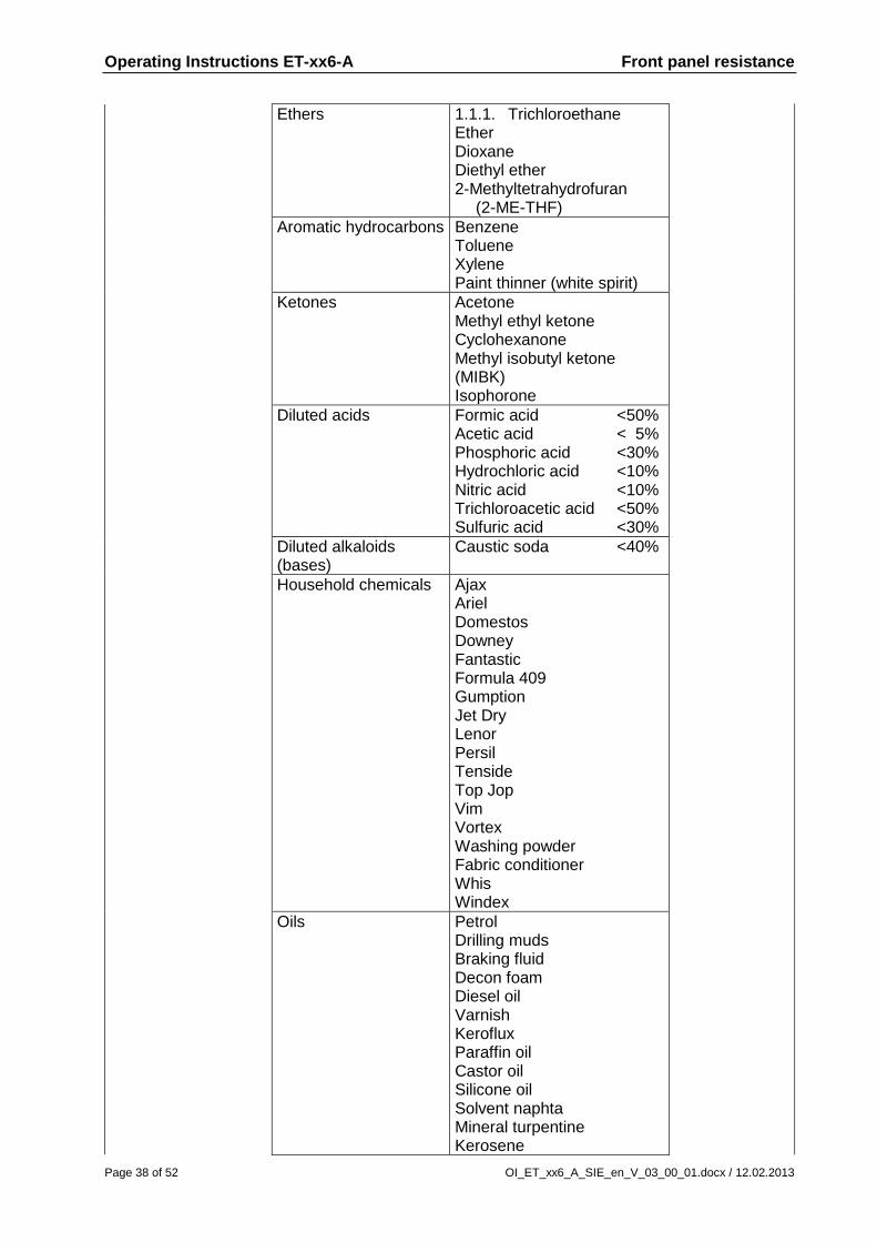
Ethers 1.1.1. Trichloroethane Ether Dioxane Diethyl ether 2-Methyltetrahydrofuran (2-ME-THF)
Aromatic hydrocarbons Benzene Toluene Xylene Paint thinner (white spirit)
Ketones Acetone Methyl ethyl ketone Cyclohexanone Methyl isobutyl ketone (MIBK) Isophorone
Diluted acids Formic acid <50% Acetic acid < 5% Phosphoric acid <30% Hydrochloric acid <10% Nitric acid <10% Trichloroacetic acid <50% Sulfuric acid <30%
Diluted alkaloids (bases)
Caustic soda <40%
Household chemicals Ajax Ariel Domestos Downey Fantastic Formula 409 Gumption Jet Dry Lenor Persil Tenside Top Jop Vim Vortex Washing powder Fabric conditioner Whis Windex
Oils Petrol Drilling muds Braking fluid Decon foam Diesel oil Varnish Keroflux Paraffin oil Castor oil Silicone oil Solvent naphta Mineral turpentine Kerosene

Operating Instructions ET-xx6-A Front panel resistance
OI_ET_xx6_A_SIE_en_V_03_00_01.docx / 12.02.2013 Page 39 of 52
No specific material class
Acetonitrile Alkali carbonate Dichromates Potassium dichromate Caustic soda <20% Dibutyl phthalate Dioctyl phthalate Iron II chloride (FeCl2) Iron II chloride (FeCl3) Haloalkanes Potassium soap Potassium hydroxide <30% Sodium bisulfate Tetrachloroethylene Salt water Trichloroethylene Water Hydrogen peroxide >25%
Property Resistance Test method
Mechanic (keyboard)
Service life after imprint
Operating force
MIT folding resistance
5 million touches max. 50 N >20000 folding operations
Autotype method ASTM D2176
Mechanic (touch screen)
point activation
1 million activations at any single point
3M method
Thermal
Dimensional
Dimension stability
Max. 0.2% at 120° longitudinal Typically 0.1%
Autotype method
18.3.3 Touch screen
Property Chemical material
class / group Chemical
substances Test method
Chemical
Chemical resistance (see front membrane) (see front membrane)
(see front membrane)
Property Resistance Test method
Mechanical
Service life after imprint
MIT folding resistance
(see front membrane)
(see front membrane)
Thermal
Dimensional
Dimension stability
(see front membrane)
(see front membrane)

Operating Instructions ET-xx6-A Front panel resistance
Page 40 of 52 OI_ET_xx6_A_SIE_en_V_03_00_01.docx / 12.02.2013
18.3.4 Front panel seal
Property Chemical material
class / group Chemical
substances Test method
Chemical
Chemical resistance
Alcohols
Glycerol
DIN 53461
Aldehydes Formaldehyde
Ketones Acetone
Household chemicals Detergents Soap suds
Oils Petrol Diesel oil Heizöl Hydrauliköl Leinöl
Property Resistance Test method
Mechanical
(No information available at present)
Thermal
Installation area
-30 to 80°C
DIN 53461
18.3.5 Rückdeckeldichtung
Property Chemical material
class / group Chemical
substances Test method
Chemical
Chemical resistance
Alcohols
Methanol Glycerol
DIN 53461
Aldehydes Formaldehyde
Amines Ammonia
Diluted acids Sulfuric acid 25%
Household chemicals Detergents Soap suds
Oils Petrol Braking fluid Mineral oils Engine oils Axle grease / lube oil
Property Resistance Test method
Mechanical
(No information available at present)
Thermal
Installation area
-60 to 200°C
DIN 53461

Operating Instructions ET-xx6-A General Information
OI_ET_xx6_A_SIE_en_V_03_00_01.docx / 12.02.2013 Page 41 of 52
19 General Information
The General Information below ONLY applies to the Panel PC Ex series of operator interfaces, and NOT to the Thin Client Ex series.
19.1 Keyboard features
Pressing two keys at once (e.g. F1 + F7) is not supported by the operator interfaces ! In such a case, the system considers the key that was pressed first as "active" and implements the associated functions and / or key bit functions ! The key pressed second is ignored.
Pressing any three of the following keys at the same time has the same effect as pressing Ctrl + Alt + Del !
The keys are: F1, F2, F7 and F8.
ET-406-A only:
Pressing the S1 – S10 softkeys on the ET-406-A has the same effect as pressing the numerical keys 0 – 9.
As an alternative, you may also allocate the Shift + F1 – Shift + F10 functions to the S1 – S10 keys.
If this is required, it must be stated when ordering, as it can only be done by the manufacturer before delivery.

Operating Instructions ET-xx6-A General Information
Page 42 of 52 OI_ET_xx6_A_SIE_en_V_03_00_01.docx / 12.02.2013
19.2 ET-4x6-A (Panel PC)
19.2.1 Licensing issues
The Panel PC Ex series operator interfaces are fully pre-installed with the Windows XP Embedded, Windows XP Professional or Windows 7 Ultimate operating systems. The license sticker is affixed on the back of the operator interface, next to the type plate. Please note that according to the license issued for Windows XP Embedded the application of this system as an Office PC is not permitted. 19.2.2 Recovery Stick
To restore your Panel PC Ex device to its original state you will need a Recovery Stick, which is available as an optional extra. This recovery stick (USB-drive, also available intrinsically safe) contains the factory image, with which the system can be restored to delivery status within a very short time. Please note that you can restore the operator interfaces to their original state only with the aid of the Recovery Stick.
As an option, the recovery stick can also contain a backup software, with which you can back up your own device configuration.
19.2.3 Back-up
Please note that it is the sole responsibility of the operator to generate a back-up of the operator interfaces and their overall function.
We strongly recommend such a back-up to be stored on an external storage medium (USB stick / recovery stick, CD, DVD or similar) or on the company network.
19.2.4 Initial start-up
19.2.4.1 Initial start-up XP Pro/WIN 7
When the Panel PC Ex operator interfaces are run for the first time with the Windows XP Professional or Windows 7 Ultimate operating systems, this requires a keyboard that must be connected via the VB-USB-ISNT1 cable included in the delivery ! See also: Software installation with external USB devices
19.2.4.2 Initial start-up XP Embedded
When the device is started for the first time, a Wizard starts where users have to select certain settings. Please follow the instructions of the Wizard carefully.

Operating Instructions ET-xx6-A General Information
OI_ET_xx6_A_SIE_en_V_03_00_01.docx / 12.02.2013 Page 43 of 52
19.2.5 Switching off/closing down
The Microsoft Windows operating system stores key data in the main memory, regardless of the application, and has to store this data on the hard disk before the PC / operator interface is switched off.
It is therefore important for the safe and correct operation that the operator interface is
closed down properly (see illustration below) and NOT simply switched off.
Otherwise the existing image of the device may be damaged, rendering the operator interface non-functioning.
After the data has been stored, Windows informs the user that the device can now be switched off.
Only switch off the device once you have received this message. 19.2.5.1 Note on XP Embedded
When using the Windows XP Embedded operating system on the Panel PC Ex series operator interfaces, the C:\ system drive can be protected from unauthorised writing. This is NOT the case with Windows XP Professional or Windows 7 Ultimate ! Recommendation: In the case of applications that require constant writing into memory, the manufacturer recommends you use external storage media (USB sticks, network servers) for these write processes.

Operating Instructions ET-xx6-A General Information
Page 44 of 52 OI_ET_xx6_A_SIE_en_V_03_00_01.docx / 12.02.2013
19.2.6 Installation Windows XP Professional
After installing the Windows XP Professional Image, the following message will pop up when starting up the device again: The following services are dependent on the distributed transaction coordinator service. Stopping the distributed transaction coordinator service will also stop these services. Message Queuing Do you want to continue this operation ?
The MSDTC service is necessary for the SQL server, which in turn is necessary for Siemens WinCC. For this reason, the message MUST be confirmed with YES, otherwise the start-up of this service will fail.

Operating Instructions ET-xx6-A CSA Control Drawing
OI_ET_xx6_A_SIE_en_V_03_00_01.docx / 12.02.2013 Page 45 of 52
20 CSA Control Drawing
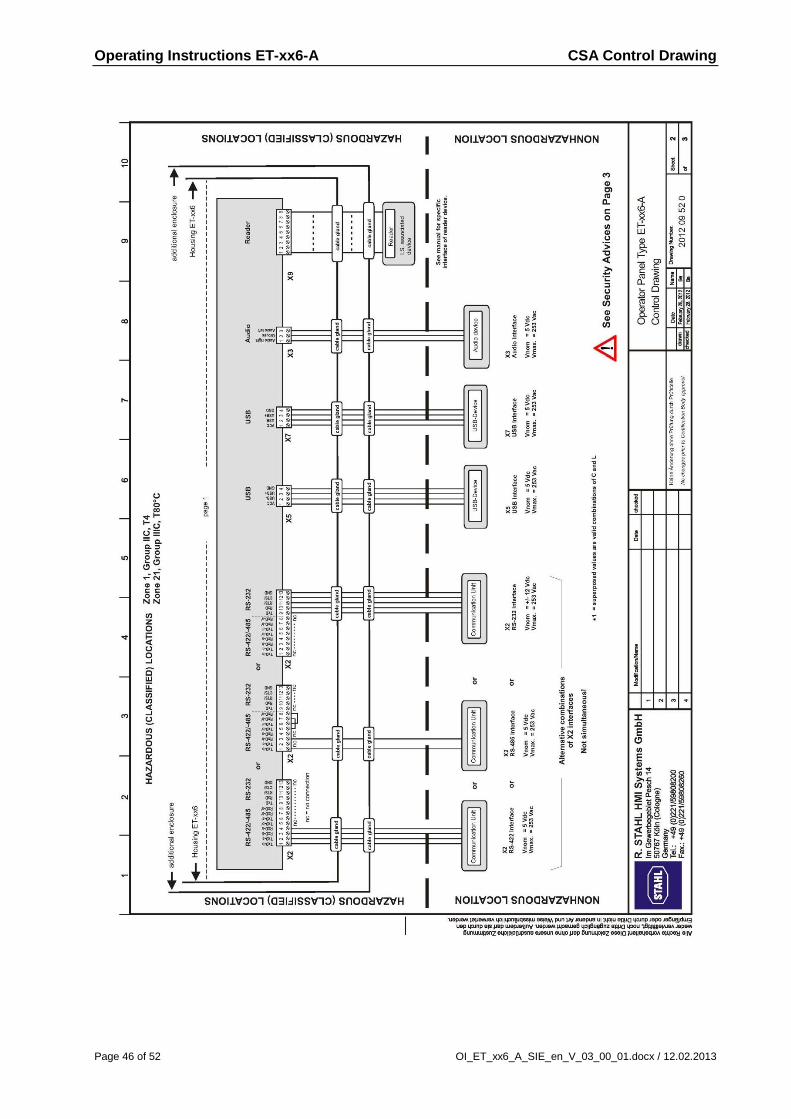
Operating Instructions ET-xx6-A CSA Control Drawing
Page 46 of 52 OI_ET_xx6_A_SIE_en_V_03_00_01.docx / 12.02.2013

Operating Instructions ET-xx6-A CSA Control Drawing
OI_ET_xx6_A_SIE_en_V_03_00_01.docx / 12.02.2013 Page 47 of 52

Operating Instructions ET-xx6-A Declaration of EC conformity
Page 48 of 52 OI_ET_xx6_A_SIE_en_V_03_00_01.docx / 12.02.2013
21 Declaration of EC conformity

Operating Instructions ET-xx6-A Release notes
OI_ET_xx6_A_SIE_en_V_03_00_01.docx / 12.02.2013 Page 49 of 52
22 Release notes
The chapter entitled "Release Notes" contains all the changes made in every version of the Operating Instructions. Version 03.00.00
First edition with HW-Rev. 3 SIE
Including of data cable length in" technical data"
Including of Windows 7 Ultimate in "note on XP Embedded" Version 03.00.01
Text and layout changes
Changing of "technical data"
Text of type code adapted
Inclusion of note to hard disk "usage instead of a flash memory"


Siemens AG Industry Sector Postfach 48 48 90327 NÜRNBERG DEUTSCHLAND


![SIMATIC HMI Thin Client Ex Notes - Siemens...Operating Instructions Thin Client Ex Table of contents Page 8 of 40 OI_ThinClient_Ex_en_V_02_05[04]_12.docx / 01.06.2012 4 Assembly and](https://img.pdfslide.net/doc/110x75/5f1a99e82a054c38c1376adc/simatic-hmi-thin-client-ex-notes-siemens-operating-instructions-thin-client.jpg)