Embed Size (px)
Citation preview
___________________
___________________
___________________
___________________
SIMATIC NET
PC software Industrial Communication with PG/PC Volume 1 - Basics
System Manual
12/2016 C79000-G8976-C172-12
Preface 1
SIMATIC NET in Industrial Communications
2
Basics of the OPC Interface 3
References 4
Siemens AG Division Process Industries and Drives Postfach 48 48 90026 NÜRNBERG GERMANY
Document order number: C79000-G8976-C172 Ⓟ 11/2016 Subject to change
Copyright © Siemens AG 2016. All rights reserved
Legal information Warning notice system
This manual contains notices you have to observe in order to ensure your personal safety, as well as to prevent damage to property. The notices referring to your personal safety are highlighted in the manual by a safety alert symbol, notices referring only to property damage have no safety alert symbol. These notices shown below are graded according to the degree of danger.
DANGER indicates that death or severe personal injury will result if proper precautions are not taken.
WARNING indicates that death or severe personal injury may result if proper precautions are not taken.
CAUTION indicates that minor personal injury can result if proper precautions are not taken.
NOTICE indicates that property damage can result if proper precautions are not taken.
If more than one degree of danger is present, the warning notice representing the highest degree of danger will be used. A notice warning of injury to persons with a safety alert symbol may also include a warning relating to property damage.
Qualified Personnel The product/system described in this documentation may be operated only by personnel qualified for the specific task in accordance with the relevant documentation, in particular its warning notices and safety instructions. Qualified personnel are those who, based on their training and experience, are capable of identifying risks and avoiding potential hazards when working with these products/systems.
Proper use of Siemens products Note the following:
WARNING Siemens products may only be used for the applications described in the catalog and in the relevant technical documentation. If products and components from other manufacturers are used, these must be recommended or approved by Siemens. Proper transport, storage, installation, assembly, commissioning, operation and maintenance are required to ensure that the products operate safely and without any problems. The permissible ambient conditions must be complied with. The information in the relevant documentation must be observed.
Trademarks All names identified by ® are registered trademarks of Siemens AG. The remaining trademarks in this publication may be trademarks whose use by third parties for their own purposes could violate the rights of the owner.
Disclaimer of Liability We have reviewed the contents of this publication to ensure consistency with the hardware and software described. Since variance cannot be precluded entirely, we cannot guarantee full consistency. However, the information in this publication is reviewed regularly and any necessary corrections are included in subsequent editions.
Industrial Communication with PG/PC Volume 1 - Basics System Manual, 12/2016, C79000-G8976-C172-12 3
Table of contents
1 Preface ................................................................................................................................................... 7
1.1 Product History ......................................................................................................................... 7
1.2 Welcome to SIMATIC NET ....................................................................................................... 8
2 SIMATIC NET in Industrial Communications ......................................................................................... 11
2.1 SIMATIC NET and the Protocols - An Overview .................................................................... 13
2.2 Industrial Communication with PROFIBUS - An Overview ..................................................... 16 2.2.1 PROFIBUS - what is it? .......................................................................................................... 16 2.2.2 PROFIBUS - how does it work? ............................................................................................. 16 2.2.3 PROFIBUS - how does it fit into the ISO-OSI reference model? ........................................... 18
2.3 Industrial Communication with Ethernet - An Overview ......................................................... 19 2.3.1 Industrial Ethernet - what is it? ............................................................................................... 19 2.3.2 Switched Ethernet - what is it? ............................................................................................... 21 2.3.3 Industrial Ethernet - which layers does it implement in the ISO/OSI reference model? ......... 21
2.4 PROFINET - An Overview ...................................................................................................... 23 2.4.1 PROFINET - what is it?........................................................................................................... 23 2.4.2 PROFINET - which communication is it based on? ................................................................ 24 2.4.3 PROFINET - which layers does PROFINET implement in the ISO/OSI reference
model? .................................................................................................................................... 25
2.5 SEND/RECEIVE protocol ....................................................................................................... 27 2.5.1 SEND/RECEIVE protocol - what is it? .................................................................................... 27 2.5.2 SEND/RECEIVE protocol - what does a typical system configuration look like? ................... 27 2.5.3 How does the SEND/RECEIVE protocol work? ..................................................................... 28 2.5.4 SEND/RECEIVE protocol - which communication services are available? ............................ 29 2.5.5 SEND/RECEIVE protocol - how is it configured? ................................................................... 30 2.5.6 SEND/RECEIVE protocol - what are the advantages and disadvantages? ........................... 31
2.6 The DP Protocol ...................................................................................................................... 33 2.6.1 DP protocol - what is it? .......................................................................................................... 33 2.6.2 DP protocol - what does a typical system configuration look like? ......................................... 35 2.6.3 DP protocol - how does it work? ............................................................................................. 36 2.6.4 DP protocol - how is it configured? ......................................................................................... 37 2.6.5 DP protocol - what are the advantages? ................................................................................ 37 2.6.6 Class 1 DP master - which communication services are available? ...................................... 37 2.6.7 Class 2 DP master - which communication services are available? ...................................... 39 2.6.8 DPC1 - which communications services are available? ......................................................... 40 2.6.9 DPC2 - which communications services are available? ......................................................... 42 2.6.10 DP slave - which communications services are available? .................................................... 43
2.7 The S7 Protocol ...................................................................................................................... 45 2.7.1 S7 protocol - what is it?........................................................................................................... 45 2.7.2 S7 protocol - what does a typical system configuration look like? ......................................... 45 2.7.3 S7 protocol - how does it work? .............................................................................................. 47 2.7.4 S7 protocol - which communication services are available? .................................................. 47
Table of contents
Industrial Communication with PG/PC Volume 1 - Basics 4 System Manual, 12/2016, C79000-G8976-C172-12
2.7.5 Fault-tolerant S7 connections, what are they? ...................................................................... 52 2.7.5.1 Fault-tolerant S7 connections, an overview ........................................................................... 53 2.7.5.2 Configuration .......................................................................................................................... 61 2.7.5.3 Diagnostics, commissioning, maintenance, operation ........................................................... 62 2.7.6 S7 protocol - how is it configured? ......................................................................................... 64 2.7.7 S7 protocol - what are the advantages and disadvantages? ................................................. 65
2.8 The SNMP Protocol ............................................................................................................... 66 2.8.1 SNMP protocol - what is it? .................................................................................................... 66 2.8.2 SNMP protocol - what does a typical system configuration look like? ................................... 66 2.8.3 SNMP protocol - how does it work? ....................................................................................... 67 2.8.4 SNMP protocol - which communication services are available? ........................................... 68 2.8.5 SNMP protocol - how is it configured? ................................................................................... 68 2.8.6 SNMP protocol - what are the advantages and disadvantages? ........................................... 69
2.9 Communication with PROFINET IO....................................................................................... 70 2.9.1 PROFINET IO - what is it? ..................................................................................................... 70 2.9.2 PROFINET IO - what does a typical system configuration look like? .................................... 71 2.9.3 PROFINET IO - how does it work? ........................................................................................ 72 2.9.4 PROFINET IO with Isochronous Real-Time Communication (IRT) ....................................... 75 2.9.5 PROFINET IO - which communication services are available? ............................................ 78 2.9.6 PROFINET IO - how is it configured? .................................................................................... 79 2.9.7 PROFINET IO - what are the advantages? ........................................................................... 80
2.10 Security in SIMATIC NET ...................................................................................................... 81
3 Basics of the OPC Interface .................................................................................................................. 83
3.1 Introduction to OPC ............................................................................................................... 84 3.1.1 OPC - what is it? .................................................................................................................... 84 3.1.2 Advantages of OPC ............................................................................................................... 85 3.1.3 OPC interface - what does it do? ........................................................................................... 86 3.1.4 OPC server - what is it? ......................................................................................................... 87 3.1.5 OPC client - what is it? ........................................................................................................... 88 3.1.6 Server and client - how do they work together? .................................................................... 89 3.1.7 Basic Terminology.................................................................................................................. 90 3.1.7.1 COM objects - what are they? ............................................................................................... 90 3.1.7.2 COM objects - how are they represented? ............................................................................ 91 3.1.7.3 COM interfaces - what do they do? ....................................................................................... 92 3.1.7.4 COM interface types - what types exist, how are they accessed? ........................................ 93
3.2 Data Access ........................................................................................................................... 95 3.2.1 Introduction to the Data Access Interface .............................................................................. 95 3.2.1.1 What can OPC Data Access do? ........................................................................................... 95 3.2.1.2 OPC data access - what is it? ................................................................................................ 95 3.2.1.3 Class model of OPC Data Access - what does it do?............................................................ 96 3.2.1.4 OPC server class - what does it do?...................................................................................... 97 3.2.1.5 OPC group class - what does it do? ...................................................................................... 97 3.2.1.6 OPC item class - what does it do? ......................................................................................... 98 3.2.1.7 OPC Data Access - what are the interface specifications? ................................................... 99
3.3 OPC Alarms & Events .......................................................................................................... 100 3.3.1 Introduction to OPC Alarms & Events .................................................................................. 100 3.3.1.1 OPC Alarms & Events - what does it mean? ....................................................................... 100 3.3.1.2 Events and event messages - what are they? ..................................................................... 100 3.3.1.3 Class model of OPC Alarms & Events - what does it do? ................................................... 101
Table of contents
Industrial Communication with PG/PC Volume 1 - Basics System Manual, 12/2016, C79000-G8976-C172-12 5
3.3.1.4 OPC event server class - what does it do? .......................................................................... 102 3.3.1.5 OPC event subscription class - what does it do? ................................................................. 103 3.3.1.6 OPC event area browser class - what does it do? ............................................................... 104 3.3.1.7 Message reception - how does it work? ............................................................................... 105 3.3.1.8 Alarms in SIMATIC S7 - how are they defined? ................................................................... 106 3.3.1.9 Alarms - what happens in practice (example)? .................................................................... 107 3.3.2 Alarms & Events Interface .................................................................................................... 109 3.3.2.1 Interfaces - which interfaces are specified for Alarms & Events? ........................................ 109
3.4 OPC XML .............................................................................................................................. 110 3.4.1 Introduction to XML and SOAP ............................................................................................. 110 3.4.1.1 XML and SOAP - what are they? .......................................................................................... 110 3.4.1.2 Web services - what do they do? .......................................................................................... 112 3.4.2 OPC XML Interface ............................................................................................................... 112 3.4.2.1 OPC XML interface - what does it do? ................................................................................. 112 3.4.2.2 OPC XML Web service - how does it work? ......................................................................... 114 3.4.2.3 Read/write simple services - what methods are there in XML?............................................ 114
3.5 OPC Unified Architecture ...................................................................................................... 116 3.5.1 Introduction to OPC UA ........................................................................................................ 116 3.5.1.1 Introduction ........................................................................................................................... 116 3.5.1.2 Security with OPC UA ........................................................................................................... 117 3.5.1.3 Types of communication of OPC UA .................................................................................... 117 3.5.1.4 The name space of OPC UA ................................................................................................ 120 3.5.1.5 Other characteristics of OPC UA .......................................................................................... 122 3.5.2 The OPC UA interface .......................................................................................................... 123 3.5.2.1 What interface specifications of the OPC Unified Architecture exist? .................................. 123 3.5.2.2 How is the connection to an OPC UA server established? .................................................. 124 3.5.2.3 How can the OPC UA namespace be browsed? .................................................................. 125 3.5.2.4 How can data be read and written? ...................................................................................... 126 3.5.2.5 How are UA data and events monitored? ............................................................................. 126 3.5.2.6 How is extra fast reading and writing achieved after registration? ....................................... 130 3.5.2.7 How do events, conditions and alarms work? ...................................................................... 131
3.6 Performance of OPC Data Access and OPC Alarms & Events in SIMATIC NET ................ 134 3.6.1 Performance - how can I make optimum use of it? .............................................................. 134 3.6.2 OPC server from SIMATIC NET in the automation world - how is it used? ......................... 136 3.6.3 OPC Server for SIMATIC NET - what are the advantages? ................................................. 137 3.6.4 OPC server from SIMATIC NET - what does it do? ............................................................. 139 3.6.5 Process data - how is optimum access achieved? ............................................................... 140 3.6.6 Group operations - how are they used? ............................................................................... 141 3.6.7 OPC cache - what is it? ........................................................................................................ 141 3.6.8 MaxAge - what is that? ......................................................................................................... 141 3.6.9 Services use the cache - how does that work (example)? ................................................... 142 3.6.10 Protocols - which can be optimized? .................................................................................... 142 3.6.11 Buffer send/receive services - why are they used? .............................................................. 143 3.6.12 Buffer send/receive services - how are they used (example)? ............................................. 144 3.6.13 Methods - how are suitable methods used? ......................................................................... 144 3.6.13.1 Synchronous access - what types exist? .............................................................................. 144 3.6.13.2 Asynchronous access - what types exist? ............................................................................ 145 3.6.13.3 Monitoring variables - what happens here? .......................................................................... 146 3.6.14 Percent Deadband - how is this parameter used? ............................................................... 148 3.6.15 Sampling rate - how is it used for specific items? ................................................................. 149

Table of contents
Industrial Communication with PG/PC Volume 1 - Basics 6 System Manual, 12/2016, C79000-G8976-C172-12
4 References .......................................................................................................................................... 153
Index ................................................................................................................................................... 155
Industrial Communication with PG/PC Volume 1 - Basics System Manual, 12/2016, C79000-G8976-C172-12 7
Preface 1 1.1 Product History
Enhancements in the SIMATIC NET PC Software The SIMATIC NET PC software as of V8.1 supports 64-bit operating systems.
With the SIMATIC NET PC software as of V8.2 VMware ESXi is supported. ***
With OPC Unified Architecture Version 1.01, the previous functionality has been enhanced.
The SIMATIC NET OPC UA servers also support:
● Transparent server redundancy for the S7 protocol. *
● Configurable option of high-speed local communication. *
● Configurable option of user authentication. *
General new features in SIMATIC NET OPC:
● The new OPC data control for the .NET interfaces now supports OPC UA with simple certificate management. This makes simple graphic OPC UA programming available for .NET as well. *
● A new symbol editor now allows symbol files of the high-performance type ATI to be processed. CSV import/export and STI import are now available. **
(*)= You will find more detailed information in "Industrial Communication with PG/PC Volume 2 - Interfaces" (**)= You will find more detailed information in "Commissioning PC Stations" (***)= You will find more detailed information in the installation manual for the "SIMATIC NET PC Software" V8.2 and higher
Preface 1.2 Welcome to SIMATIC NET
Industrial Communication with PG/PC Volume 1 - Basics 8 System Manual, 12/2016, C79000-G8976-C172-12
1.2 Welcome to SIMATIC NET
SIMATIC NET - Pioneering successful solutions in black and white Now that you have made your decision, we'll be at your side. This documentation will be your companion on your way to successful application of SIMATIC NET. It will provide you with a straightforward and clear introduction to the topics and will show you how to install and configure individual components and how to create your own programs based on OPC. You will see the opportunities that industrial communication with SIMATIC NET can open up for you, for your automation solutions, and, above all, for the success of your company.
SIMATIC NET - The right decision You know the advantages of distributed automation systems and want to make optimum use of industrial communication. You expect a strong partner and innovative, reliable products. With SIMATIC NET, you've made the right choice.
This documentation will build up your knowledge and let you profit from the know-how and expertise of the specialists.
Are you a beginner? Then you can familiarize yourself systematically. Start in this Volume 1 with the introduction to industrial communication. There you will find all the necessary information on the communications principles and range of functions of the SIMATIC NET OPC server. Read the basics of the OPC interface, familiarize yourself with the protocols and their advantages and functions.
Are you a professional? Then you can get going straight away. Volume 2 provides you with all the information you require to work with SIMATIC NET.
Volume 2 – Interfaces, entry ID:
61630140 (http://support.automation.siemens.com/WW/view/en/61630140)
Do you find examples useful? The supplied sample programs will provide you with a flexible basis with which you can put your own ideas into practice.
Trademarks The following and possibly other names not identified by the registered trademark sign ® are registered trademarks of Siemens AG:
SIMATIC NET, HARDNET, SOFTNET, CP 1612, CP 1613, CP 5612, CP 5613, CP 5614, CP 5622
Preface 1.2 Welcome to SIMATIC NET
Industrial Communication with PG/PC Volume 1 - Basics System Manual, 12/2016, C79000-G8976-C172-12 9
Industry Online Support In addition to the product documentation, the comprehensive online information platform of Siemens Industry Online Support at the following Internet address: (http://support.automation.siemens.com/WW/llisapi.dll?func=cslib.csinfo2&aktprim=99&lang=en)
Apart from news, there you will also find:
● Project information: Manuals, FAQs, downloads, application examples etc.
● Contacts, Technical Forum
● The option submitting a support query: (https://support.automation.siemens.com/WW/llisapi.dll?func=cslib.csinfo&lang=en&objid=38718979&caller=view)
● Our service offer:
Right across our products and systems, we provide numerous services that support you in every phase of the life of your machine or system - from planning and implementation to commissioning, through to maintenance and modernization.
You will find contact data on the Internet at the following address: (http://www.automation.siemens.com/partner/guiwelcome.asp?lang=en)
SITRAIN - Training for Industry The training offer includes more than 300 courses on basic topics, extended knowledge and special knowledge as well as advanced training for individual sectors - available at more than 130 locations. Courses can also be organized individually and held locally at your location.
You will find detailed information on the training curriculum and how to contact our customer consultants at the following Internet address:
(www.siemens.com/sitrain)
Security information Siemens provides products and solutions with industrial security functions that support the secure operation of plants, systems, machines and networks.
In order to protect plants, systems, machines and networks against cyber threats, it is necessary to implement – and continuously maintain – a holistic, state-of-the-art industrial security concept. Siemens’ products and solutions only form one element of such a concept.
Customer is responsible to prevent unauthorized access to its plants, systems, machines and networks. Systems, machines and components should only be connected to the enterprise network or the internet if and to the extent necessary and with appropriate security measures (e.g. use of firewalls and network segmentation) in place.
Additionally, Siemens’ guidance on appropriate security measures should be taken into account. For more information about industrial security, please visit http://www.siemens.com/industrialsecurity
Preface 1.2 Welcome to SIMATIC NET
Industrial Communication with PG/PC Volume 1 - Basics 10 System Manual, 12/2016, C79000-G8976-C172-12
Siemens’ products and solutions undergo continuous development to make them more secure. Siemens strongly recommends to apply product updates as soon as available and to always use the latest product versions. Use of product versions that are no longer supported, and failure to apply latest updates may increase customer’s exposure to cyber threats.
To stay informed about product updates, subscribe to the Siemens Industrial Security RSS Feed under https://support.industry.siemens.com/cs/ww/de/ps/15247/pm
SIMATIC NET glossary Explanations of many of the specialist terms used in this documentation can be found in the SIMATIC NET glossary.
You will find the SIMATIC NET glossary on the Internet at the following address:
50305045 (http://support.automation.siemens.com/WW/view/en/50305045)
Industrial Communication with PG/PC Volume 1 - Basics System Manual, 12/2016, C79000-G8976-C172-12 11
SIMATIC NET in Industrial Communications 2
Overview The material in this chapter will help you if you want to get to know the communications principles and range of functions of the various protocols in Industrial communication with SIMATIC NET®.
It explains the basics of the PROFIBUS and Industrial Ethernet communication networks, tells you how the protocols implemented for these communication networks in SIMATIC NET work and lists the advantages and disadvantages of these protocols. At the end of the chapter, you will see an overview of the technology and application of PROFINET and how it is implemented in SIMATIC NET.
When you have worked through the chapter, you should be in a position to identify the most suitable tools with which you can solve your automation tasks.
What does SIMATIC NET actually mean? Industrial communication is the backbone of modern automation solutions. The communication networks and products involved allow totally integrated communication between the widest possible variety of automation components and devices.
SIMATIC NET is the name of an entire family of communications networks and products from Siemens. The various networks meet the widest possible range of performance and application requirements in automation engineering.
What does SIMATIC NET provide? SIMATIC NET provides solutions for individual customer requirements in industrial communication. The communications networks and products from SIMATIC NET are a component of Totally Integrated Automation (TIA) from Siemens. On this basis, branch-specific automation solutions can be implemented with comprehensive and highly integrated communications functions. SIMATIC NET simplifies the commissioning of automation systems regardless of the communication networks and products used.
In terms of their performance and range of functions, the communication networks and products of SIMATIC NET can be represented in the form of an automation pyramid.
SIMATIC NET in Industrial Communications
Industrial Communication with PG/PC Volume 1 - Basics 12 System Manual, 12/2016, C79000-G8976-C172-12
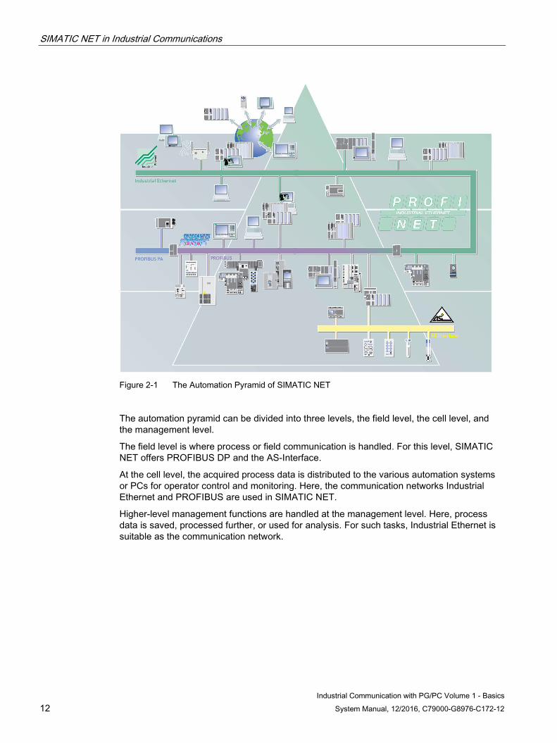
Figure 2-1 The Automation Pyramid of SIMATIC NET
The automation pyramid can be divided into three levels, the field level, the cell level, and the management level.
The field level is where process or field communication is handled. For this level, SIMATIC NET offers PROFIBUS DP and the AS-Interface.
At the cell level, the acquired process data is distributed to the various automation systems or PCs for operator control and monitoring. Here, the communication networks Industrial Ethernet and PROFIBUS are used in SIMATIC NET.
Higher-level management functions are handled at the management level. Here, process data is saved, processed further, or used for analysis. For such tasks, Industrial Ethernet is suitable as the communication network.
SIMATIC NET in Industrial Communications 2.1 SIMATIC NET and the Protocols - An Overview
Industrial Communication with PG/PC Volume 1 - Basics System Manual, 12/2016, C79000-G8976-C172-12 13
2.1 SIMATIC NET and the Protocols - An Overview
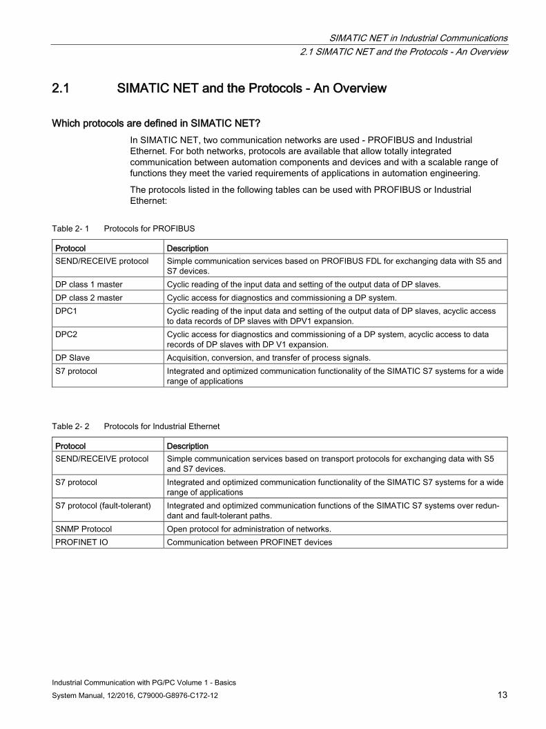
Which protocols are defined in SIMATIC NET? In SIMATIC NET, two communication networks are used - PROFIBUS and Industrial Ethernet. For both networks, protocols are available that allow totally integrated communication between automation components and devices and with a scalable range of functions they meet the varied requirements of applications in automation engineering.
The protocols listed in the following tables can be used with PROFIBUS or Industrial Ethernet:
Table 2- 1 Protocols for PROFIBUS
Protocol Description SEND/RECEIVE protocol Simple communication services based on PROFIBUS FDL for exchanging data with S5 and
S7 devices. DP class 1 master Cyclic reading of the input data and setting of the output data of DP slaves. DP class 2 master Cyclic access for diagnostics and commissioning a DP system. DPC1 Cyclic reading of the input data and setting of the output data of DP slaves, acyclic access
to data records of DP slaves with DPV1 expansion. DPC2 Cyclic access for diagnostics and commissioning of a DP system, acyclic access to data
records of DP slaves with DP V1 expansion. DP Slave Acquisition, conversion, and transfer of process signals. S7 protocol Integrated and optimized communication functionality of the SIMATIC S7 systems for a wide
range of applications
Table 2- 2 Protocols for Industrial Ethernet
Protocol Description SEND/RECEIVE protocol Simple communication services based on transport protocols for exchanging data with S5
and S7 devices. S7 protocol Integrated and optimized communication functionality of the SIMATIC S7 systems for a wide
range of applications S7 protocol (fault-tolerant) Integrated and optimized communication functions of the SIMATIC S7 systems over redun-
dant and fault-tolerant paths. SNMP Protocol Open protocol for administration of networks. PROFINET IO Communication between PROFINET devices
SIMATIC NET in Industrial Communications 2.1 SIMATIC NET and the Protocols - An Overview
Industrial Communication with PG/PC Volume 1 - Basics 14 System Manual, 12/2016, C79000-G8976-C172-12
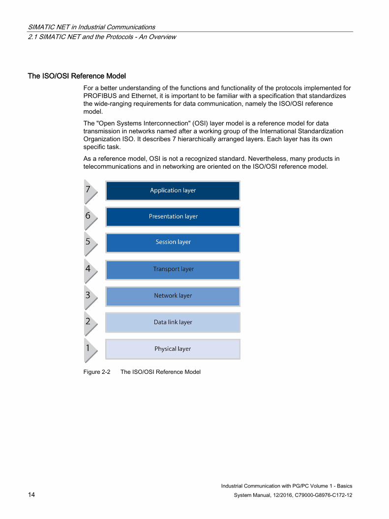
The ISO/OSI Reference Model For a better understanding of the functions and functionality of the protocols implemented for PROFIBUS and Ethernet, it is important to be familiar with a specification that standardizes the wide-ranging requirements for data communication, namely the ISO/OSI reference model.
The "Open Systems Interconnection" (OSI) layer model is a reference model for data transmission in networks named after a working group of the International Standardization Organization ISO. It describes 7 hierarchically arranged layers. Each layer has its own specific task.
As a reference model, OSI is not a recognized standard. Nevertheless, many products in telecommunications and in networking are oriented on the ISO/OSI reference model.
Figure 2-2 The ISO/OSI Reference Model
SIMATIC NET in Industrial Communications 2.1 SIMATIC NET and the Protocols - An Overview
Industrial Communication with PG/PC Volume 1 - Basics System Manual, 12/2016, C79000-G8976-C172-12 15
Which layers are defined in the ISO/OSI reference model? The 7 layers specified in the model are arranged in three functional levels. The first and second layers represent the level most closely associated with the hardware, the third and fourth layers form the transmission level, and layers 5 to 7 implement the level most closely associated with the application. The layers are defined as follows:
● Layer 1: The physical layer is responsible for the physical connection between two devices. It transfers the data from one device to another over a network.
● Layer 2: The data link layer is responsible for reliable transfer of the data. It groups the bits into blocks of data and adds address information required to transmit the data from one device to the other. The slave is also responsible for error detection on the link.
● Layer 3: The network layer is responsible for routing and correct forwarding of the blocks of data. It handles the addressing of the frames and how they are routed in the network. An example of this layer is the Internet protocol (IP).
● Layer 4: The transport layer coordinates the transmission of data packets. It checks whether all packets have been received completely. To achieve this, transport connections between two devices are made available. A typical example of layer 4 is the Transmission Control Protocol (TCP).
● Layer 5: The session layer establishes a more permanent connection between the devices between which data is to be transferred. This layer is responsible for establishing and terminating the connection and also maintaining a connection.
● Layer 6: The presentation layer is responsible for converting data into the format required for the specific application. The data is also prepared for transport. This includes compression and encoding of data.
● Layer 7: The application layer provides applications that receive data for further processing or provide data for transmission. Classic examples of such applications are mail programs or Internet browsers.
SIMATIC NET in Industrial Communications 2.2 Industrial Communication with PROFIBUS - An Overview
Industrial Communication with PG/PC Volume 1 - Basics 16 System Manual, 12/2016, C79000-G8976-C172-12
2.2 Industrial Communication with PROFIBUS - An Overview
2.2.1 PROFIBUS - what is it?
This is PROFIBUS PROFIBUS is the open and internationally standardized (EN50170) bus system for process and field communication with field devices and for data communication within an automation cell. The possible uses of PROFIBUS range from production and process automation to building automation.
What are the main features of PROFIBUS? The main features of PROFIBUS are as follows:
● Data transmission over cost-effective communications media such as twisted pair.
● A wide range of applications since programmable controllers and operator control and monitoring devices communicate over a uniform bus.
● Standardized data communication complying with EN 50170, EC 61158 (services and protocol) and IEC 61784.
● Commissioning, configuration, and troubleshooting can be performed at any point in the bus segment.
● Safe investment since existing PROFIBUS systems can be expanded with no detrimental effects.
2.2.2 PROFIBUS - how does it work?
How PROFIBUS Works The PROFIBUS specification is flexible enough to allow the implementation of various protocols optimized for specific tasks in different areas of application. The FDL data-link layer (layer 2 of the ISO/OSI reference model) ensures uniform control of access to the bus using token passing.
SIMATIC NET in Industrial Communications 2.2 Industrial Communication with PROFIBUS - An Overview
Industrial Communication with PG/PC Volume 1 - Basics System Manual, 12/2016, C79000-G8976-C172-12 17
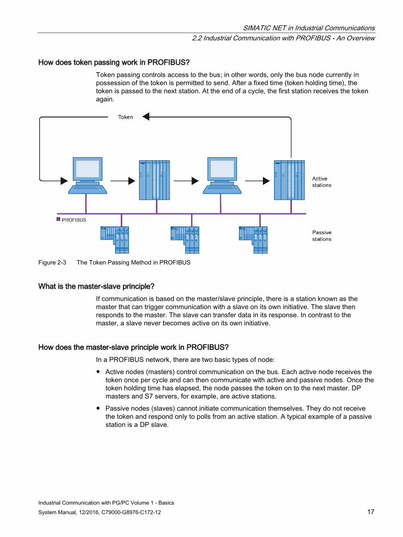
How does token passing work in PROFIBUS? Token passing controls access to the bus; in other words, only the bus node currently in possession of the token is permitted to send. After a fixed time (token holding time), the token is passed to the next station. At the end of a cycle, the first station receives the token again.
Figure 2-3 The Token Passing Method in PROFIBUS
What is the master-slave principle? If communication is based on the master/slave principle, there is a station known as the master that can trigger communication with a slave on its own initiative. The slave then responds to the master. The slave can transfer data in its response. In contrast to the master, a slave never becomes active on its own initiative.
How does the master-slave principle work in PROFIBUS? In a PROFIBUS network, there are two basic types of node:
● Active nodes (masters) control communication on the bus. Each active node receives the token once per cycle and can then communicate with active and passive nodes. Once the token holding time has elapsed, the node passes the token on to the next master. DP masters and S7 servers, for example, are active stations.
● Passive nodes (slaves) cannot initiate communication themselves. They do not receive the token and respond only to polls from an active station. A typical example of a passive station is a DP slave.
SIMATIC NET in Industrial Communications 2.2 Industrial Communication with PROFIBUS - An Overview
Industrial Communication with PG/PC Volume 1 - Basics 18 System Manual, 12/2016, C79000-G8976-C172-12
2.2.3 PROFIBUS - how does it fit into the ISO-OSI reference model?
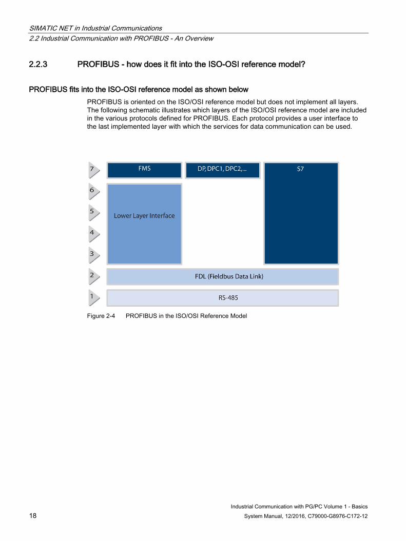
PROFIBUS fits into the ISO-OSI reference model as shown below PROFIBUS is oriented on the ISO/OSI reference model but does not implement all layers. The following schematic illustrates which layers of the ISO/OSI reference model are included in the various protocols defined for PROFIBUS. Each protocol provides a user interface to the last implemented layer with which the services for data communication can be used.
Figure 2-4 PROFIBUS in the ISO/OSI Reference Model
SIMATIC NET in Industrial Communications 2.3 Industrial Communication with Ethernet - An Overview
Industrial Communication with PG/PC Volume 1 - Basics System Manual, 12/2016, C79000-G8976-C172-12 19
2.3 Industrial Communication with Ethernet - An Overview
2.3.1 Industrial Ethernet - what is it?
This is Industrial Ethernet Industrial Ethernet is a powerful communication network complying with the international standard IEEE 802.3 (Ethernet) and was designed for the requirements in industrial applications.
What are the properties of Industrial Ethernet? Its main features are as follows:
● Networking of different areas of application such as management and plant floor.
● Robust design and electromagnetic immunity.
● High transmission performance (100 Mbps and 1 Gbps).
● Support of various transmission media, for example twisted pair or fiber-optic cable.
● Scalable performance with switched Ethernet technology.
● High availability with redundant network topologies.
● Transmission of large amounts of data by using various transport protocols.
● Real-time transmission with PROFINET IO is available.
SIMATIC NET in Industrial Communications 2.3 Industrial Communication with Ethernet - An Overview
Industrial Communication with PG/PC Volume 1 - Basics 20 System Manual, 12/2016, C79000-G8976-C172-12
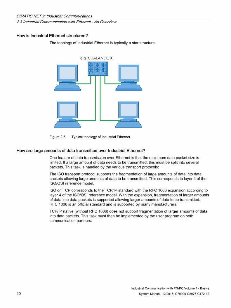
How is Industrial Ethernet structured? The topology of Industrial Ethernet is typically a star structure.
Figure 2-5 Typical topology of Industrial Ethernet
How are large amounts of data transmitted over Industrial Ethernet? One feature of data transmission over Ethernet is that the maximum data packet size is limited. If a large amount of data needs to be transmitted, this must be split into several packets. This task is handled by the various transport protocols:
The ISO transport protocol supports the fragmentation of large amounts of data into data packets allowing large amounts of data to be transmitted. This corresponds to layer 4 of the ISO/OSI reference model.
ISO on TCP corresponds to the TCP/IP standard with the RFC 1006 expansion according to layer 4 of the ISO/OSI reference model. With the expansion, fragmentation of larger amounts of data into data packets is supported allowing larger amounts of data to be transmitted. RFC 1006 is an official standard and is supported by many manufacturers.
TCP/IP native (without RFC 1006) does not support fragmentation of larger amounts of data into data packets. This task must then be implemented by the user program on both communication partners.
SIMATIC NET in Industrial Communications 2.3 Industrial Communication with Ethernet - An Overview
Industrial Communication with PG/PC Volume 1 - Basics System Manual, 12/2016, C79000-G8976-C172-12 21
2.3.2 Switched Ethernet - what is it?
This is Switched Ethernet Switched Ethernet divides the network into segments linked by switches.
What are the advantages of switched Ethernet? ● Dividing the network into segments reduces the total network load.
● Each segment has the full data transmission rate available.
● Collisions between data packets in full duplex mode are not possible since a separate line is available for sending and receiving.
2.3.3 Industrial Ethernet - which layers does it implement in the ISO/OSI reference model?
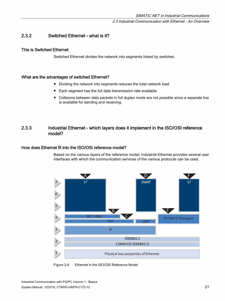
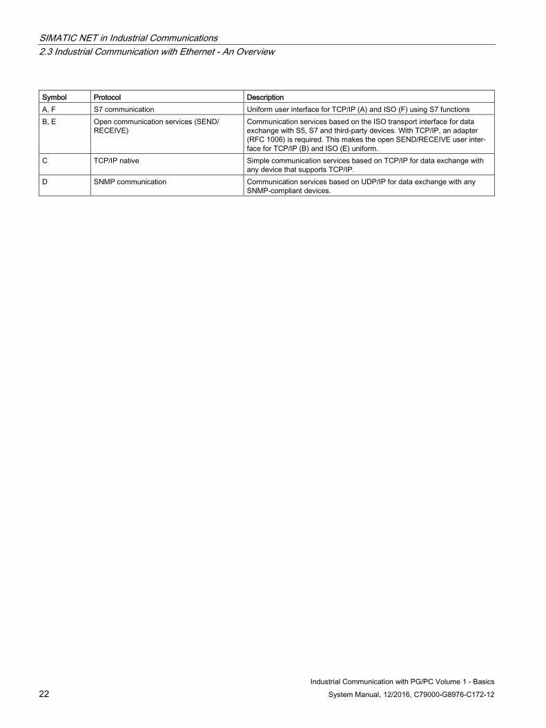
How does Ethernet fit into the ISO/OSI reference model? Based on the various layers of the reference model, Industrial Ethernet provides several user interfaces with which the communication services of the various protocols can be used.
Figure 2-6 Ethernet in the ISO/OSI Reference Model
SIMATIC NET in Industrial Communications 2.3 Industrial Communication with Ethernet - An Overview
Industrial Communication with PG/PC Volume 1 - Basics 22 System Manual, 12/2016, C79000-G8976-C172-12
Symbol Protocol Description A, F S7 communication Uniform user interface for TCP/IP (A) and ISO (F) using S7 functions B, E Open communication services (SEND/
RECEIVE) Communication services based on the ISO transport interface for data exchange with S5, S7 and third-party devices. With TCP/IP, an adapter (RFC 1006) is required. This makes the open SEND/RECEIVE user inter-face for TCP/IP (B) and ISO (E) uniform.
C TCP/IP native Simple communication services based on TCP/IP for data exchange with any device that supports TCP/IP.
D SNMP communication Communication services based on UDP/IP for data exchange with any SNMP-compliant devices.
SIMATIC NET in Industrial Communications 2.4 PROFINET - An Overview
Industrial Communication with PG/PC Volume 1 - Basics System Manual, 12/2016, C79000-G8976-C172-12 23
2.4 PROFINET - An Overview
2.4.1 PROFINET - what is it?
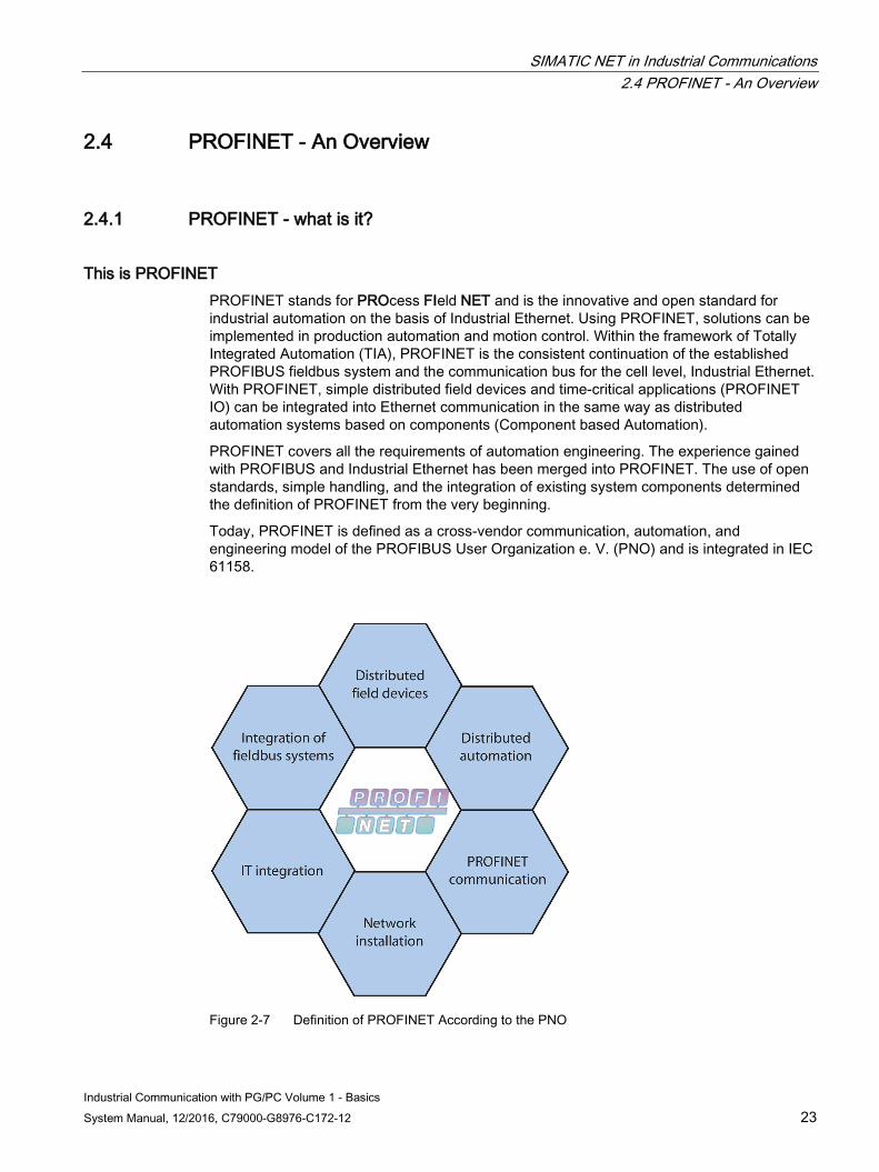
This is PROFINET PROFINET stands for PROcess FIeld NET and is the innovative and open standard for industrial automation on the basis of Industrial Ethernet. Using PROFINET, solutions can be implemented in production automation and motion control. Within the framework of Totally Integrated Automation (TIA), PROFINET is the consistent continuation of the established PROFIBUS fieldbus system and the communication bus for the cell level, Industrial Ethernet. With PROFINET, simple distributed field devices and time-critical applications (PROFINET IO) can be integrated into Ethernet communication in the same way as distributed automation systems based on components (Component based Automation).
PROFINET covers all the requirements of automation engineering. The experience gained with PROFIBUS and Industrial Ethernet has been merged into PROFINET. The use of open standards, simple handling, and the integration of existing system components determined the definition of PROFINET from the very beginning.
Today, PROFINET is defined as a cross-vendor communication, automation, and engineering model of the PROFIBUS User Organization e. V. (PNO) and is integrated in IEC 61158.
Figure 2-7 Definition of PROFINET According to the PNO
SIMATIC NET in Industrial Communications 2.4 PROFINET - An Overview
Industrial Communication with PG/PC Volume 1 - Basics 24 System Manual, 12/2016, C79000-G8976-C172-12
What are the aims of PROFINET? The aims of PROFINET are as follows:
● Fully integrated communication over fieldbus and Ethernet
● Open, distributed automation
● Communication in real time
● The use of open standards
2.4.2 PROFINET - which communication is it based on?
PROFINET is based on the following communication PROFINET is based on Ethernet communication. It is scalable and offers three performance levels:
1. TCP, UDP and IP for non time-critical data such as acyclic reading and writing of data records, parameter assignment and configuration (Non Real Time / NRT)
2. Real Time (RT) high-performance communication for time-critical process data in process automation.
3. Isochrones Real Time (IRT) high-performance, deterministic, and timed communication for time-critical process data in motion control
Which real-time communication is defined in PROFINET? In automation engineering, there are applications requiring faster update and reaction times. The PROFINET standard therefore defines mechanisms for real-time communication. As mentioned above, real-time communication is scaled:
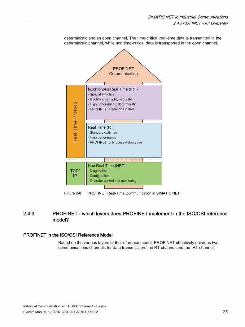
● The real-time channel (RT channel) is a real-time communication channel based directly on layer 2 of Ethernet and that uses the RT protocol. This solution minimizes the times required by the communication levels since some of them are omitted. The refresh rate of process data is improved because data is prepared for transmission faster and the user programs that receive data can process it faster. Refresh and reaction times of 5 - 10 ms are achieved.
● The isochronous real time-channel (IRT channel) was developed specifically for motion control applications. Here, there are requirements regarding the refresh and reaction time of less than 1 ms. To achieve this, the IRT channel is based on layer 2 of Fast Ethernet (100 Mbps) and uses the IRT protocol. The data is also transmitted with a time-slot controlled transmission method. Due to the time synchronization of the communication partners on Ethernet, a time slot can be specified with which communication is split into a
SIMATIC NET in Industrial Communications 2.4 PROFINET - An Overview
Industrial Communication with PG/PC Volume 1 - Basics System Manual, 12/2016, C79000-G8976-C172-12 25
deterministic and an open channel. The time-critical real-time data is transmitted in the deterministic channel, while non time-critical data is transported in the open channel.
Figure 2-8 PROFINET Real-Time Communication in SIMATIC NET
2.4.3 PROFINET - which layers does PROFINET implement in the ISO/OSI reference model?
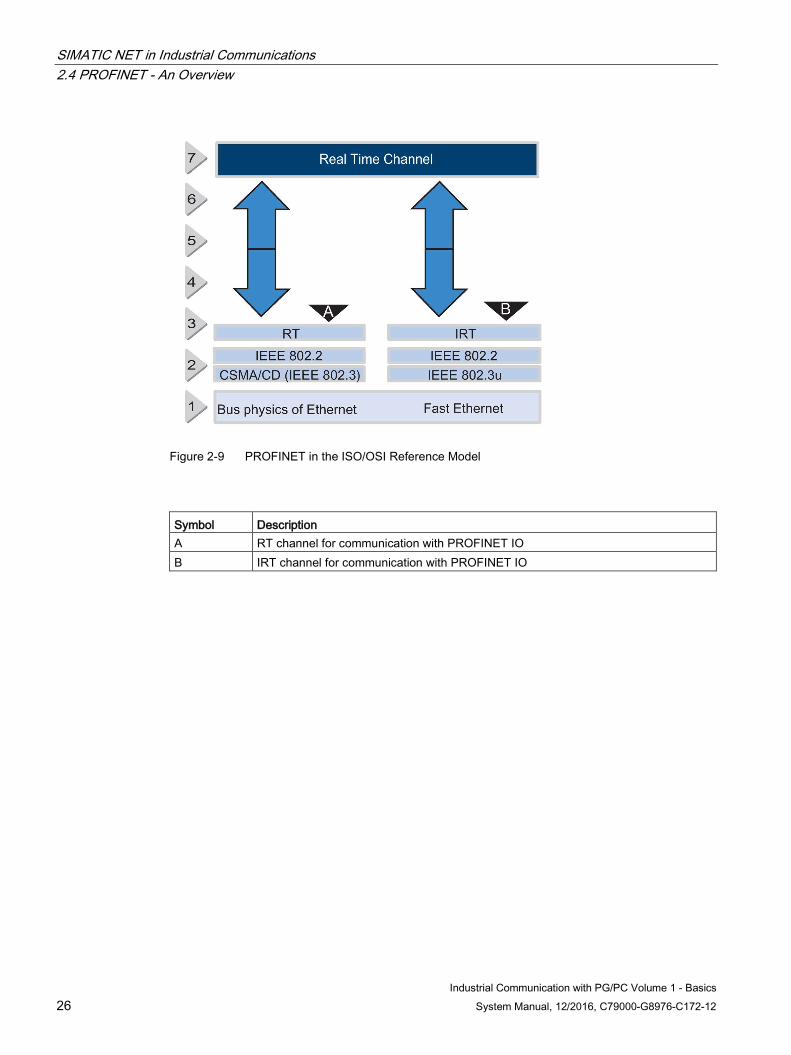
PROFINET in the ISO/OSI Reference Model Based on the various layers of the reference model, PROFINET effectively provides two communications channels for data transmission: the RT channel and the IRT channel.
SIMATIC NET in Industrial Communications 2.4 PROFINET - An Overview
Industrial Communication with PG/PC Volume 1 - Basics 26 System Manual, 12/2016, C79000-G8976-C172-12
Figure 2-9 PROFINET in the ISO/OSI Reference Model
Symbol Description A RT channel for communication with PROFINET IO B IRT channel for communication with PROFINET IO
SIMATIC NET in Industrial Communications 2.5 SEND/RECEIVE protocol
Industrial Communication with PG/PC Volume 1 - Basics System Manual, 12/2016, C79000-G8976-C172-12 27
2.5 SEND/RECEIVE protocol
2.5.1 SEND/RECEIVE protocol - what is it?
The SEND/RECEIVE Protocol The SEND/RECEIVE protocol is a communication protocol for transmission of data over PROFIBUS and Industrial Ethernet. It allows a simple data exchange between programmable controllers. Using the SEND/RECEIVE protocol, SIMATIC S5 devices, SIMATIC S7 devices, PCs, workstations and third-party devices can communicate with each other.
How does the SEND/RECEIVE protocol differ in PROFIBUS and Ethernet? ● In PROFIBUS, the SEND/RECEIVE protocol is based on FDL services, while in Ethernet,
it uses the available services of the transport layer.
● The amount of data that can be transmitted with PROFIBUS is restricted to 246 bytes and in Ethernet to 4096 bytes.
● In contrast to Ethernet, PROFIBUS does not have variable services.
2.5.2 SEND/RECEIVE protocol - what does a typical system configuration look like? This section illustrates typical system configurations in PROFIBUS and Industrial Ethernet in which data communication between different devices is implemented with the SEND/RECEIVE protocol.
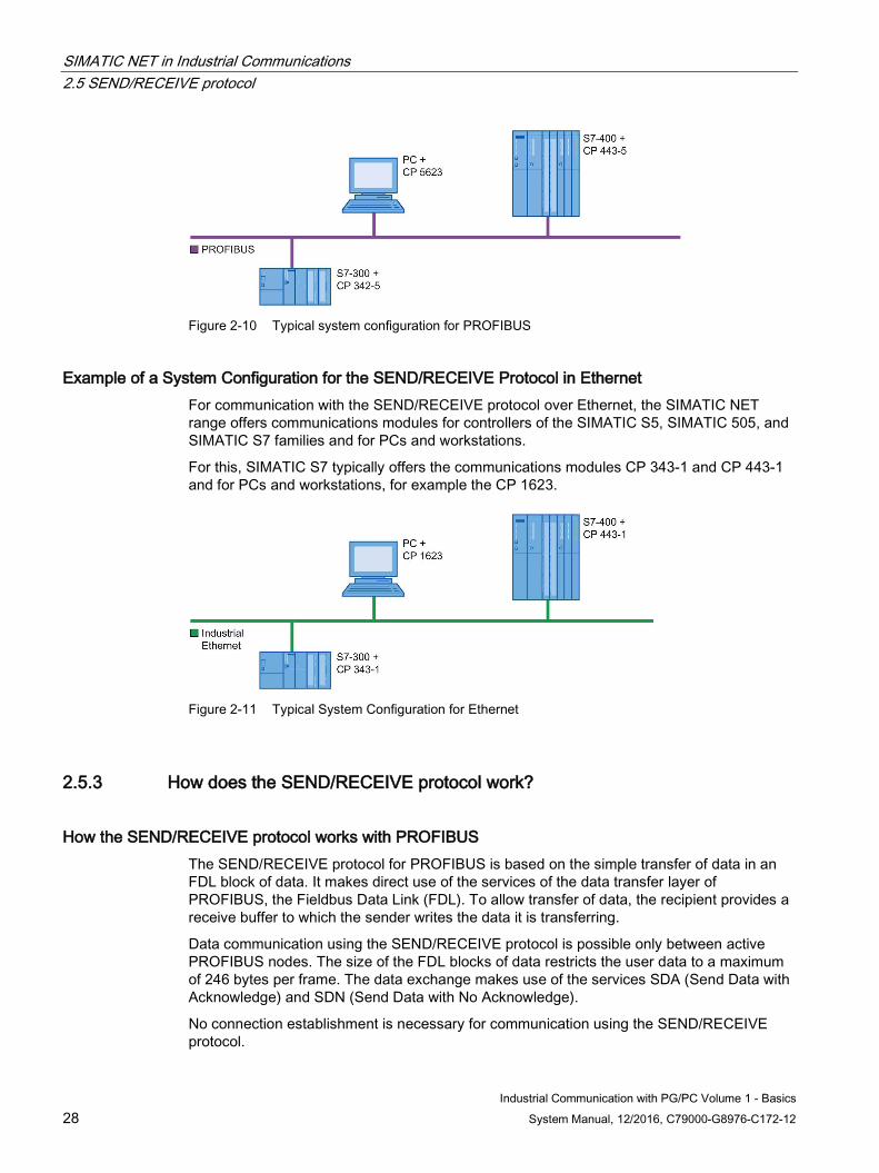
Example of a System Configuration for the SEND/RECEIVE Protocol in PROFIBUS For communication with the SEND/RECEIVE protocol over PROFIBUS, the SIMATIC NET range offers communications modules for controllers of the SIMATIC S5, SIMATIC 505, and SIMATIC S7 families and for PCs, workstations and third-party devices.
For this, SIMATIC S7 offers the communications modules CP 342-5 and CP 443-5 and for PCs, for example the CP 5623.
SIMATIC NET in Industrial Communications 2.5 SEND/RECEIVE protocol
Industrial Communication with PG/PC Volume 1 - Basics 28 System Manual, 12/2016, C79000-G8976-C172-12
Figure 2-10 Typical system configuration for PROFIBUS
Example of a System Configuration for the SEND/RECEIVE Protocol in Ethernet For communication with the SEND/RECEIVE protocol over Ethernet, the SIMATIC NET range offers communications modules for controllers of the SIMATIC S5, SIMATIC 505, and SIMATIC S7 families and for PCs and workstations.
For this, SIMATIC S7 typically offers the communications modules CP 343-1 and CP 443-1 and for PCs and workstations, for example the CP 1623.
Figure 2-11 Typical System Configuration for Ethernet
2.5.3 How does the SEND/RECEIVE protocol work?
How the SEND/RECEIVE protocol works with PROFIBUS The SEND/RECEIVE protocol for PROFIBUS is based on the simple transfer of data in an FDL block of data. It makes direct use of the services of the data transfer layer of PROFIBUS, the Fieldbus Data Link (FDL). To allow transfer of data, the recipient provides a receive buffer to which the sender writes the data it is transferring.
Data communication using the SEND/RECEIVE protocol is possible only between active PROFIBUS nodes. The size of the FDL blocks of data restricts the user data to a maximum of 246 bytes per frame. The data exchange makes use of the services SDA (Send Data with Acknowledge) and SDN (Send Data with No Acknowledge).
No connection establishment is necessary for communication using the SEND/RECEIVE protocol.
SIMATIC NET in Industrial Communications 2.5 SEND/RECEIVE protocol
Industrial Communication with PG/PC Volume 1 - Basics System Manual, 12/2016, C79000-G8976-C172-12 29
How the SEND/RECEIVE protocol works with Ethernet In contrast to data communication with PROFIBUS, with Industrial Ethernet, the SEND/RECEIVE protocol is based on the transport layer of the ISO/OSI reference model. It provides the user with the services of the transport layer such as connections, flow control and data segmentation.
The SEND/RECEIVE protocol uses the transport protocols available with Industrial Ethernet, the ISO transport protocol and the TCP/IP transport protocol with and without RFC1006.
The ISO transport protocol is specified in the international standard ISO 8073 Class 4 and provides services for the transfer of data. With the option of using data segmentation, in other words, user data can be segmented into multiple data frames on the ISO transport layer, the ISO transport service is capable of transferring large volumes of data. The ISO transport service allows communication with any communications partner that supports sending and receipt of data according to ISO transport.
The ISO-on-TCP (RFC1006) protocol corresponds to the TCP/IP standard (Transmission Control Protocol/Internet Protocol) with RFC1006. RFC1006 is necessary because TCP implements data communication without segmentation of the data in packets. RFC1006 describes how the services of the ISO transport protocol and therefore the segmentation of the data is mapped to TCP. RFC1006 is an official standard used by many vendors.
The TCP/IP native protocol (without RFC1006) allows communication with any communications partner that can capable of TCP/IP. Since the transport layer of TCP/IP delivers an unstructured data stream, the task of segmentation is left to the user. Both partners on a communications connection need to informed of the size of the data packet to be transferred so that the correct packet can be picked out of the data stream.
Data communication using the SEND/RECEIVE protocol via Ethernet is always connection-oriented. This means that a transport connection must first be established to the partner device before data can be transferred. When establishing the connection, one partner is active and the other passive. The active node initiates establishment of the connection to the partner device. Which of the two devices is responsible for connection establishment is set in the connection configuration.
2.5.4 SEND/RECEIVE protocol - which communication services are available?
The SEND/RECEIVE protocol provides the following communications services For data exchange, the SEND/RECEIVE protocol provides buffer send/receive and variable services. The buffer send/receive services are used to transfer unstructured blocks of data between two programmable controllers and are available both in PROFIBUS and in Ethernet. The variable services are used to transfer structured data; in other words, variables that are defined on the programmable controllers. Variables are so-called data objects in programmable controllers. Examples include data blocks, inputs and outputs of the I/O, bit memory, timers, counters, and system areas. The variable services can only be used on Ethernet.
SIMATIC NET in Industrial Communications 2.5 SEND/RECEIVE protocol
Industrial Communication with PG/PC Volume 1 - Basics 30 System Manual, 12/2016, C79000-G8976-C172-12
For PCs, there are several additional services in PROFIBUS intended not for data communication but rather for diagnostics and information gathering:
● Obtaining the bus parameters and the local station address
● Obtaining the list of stations on the bus
● Identification of the local station and partner stations
How do the buffer send/receive services work? The buffer services of the SEND/RECEIVE protocol include two communications services, SEND and RECEIVE.
The SEND service is used on the device from which data is sent. The sending of data must be started explicitly by the sender. The device on which the data will be received must activate the RECEIVE service before it is ready to receive.
The SEND and RECEIVE communication services for data communication on PROFIBUS are simple services without connection monitoring so that the failure of the partner device is not detected. Such monitoring can only be implemented by a suitable user program, for example, by triggering cyclic transfer of data and checking the cyclic data on the receiving device.
How do the variable services work? The variable services of the SEND/RECEIVE protocol include two communications services, FETCH and WRITE. These communications services are available only on Ethernet.
When the FETCH service executes, a job is sent from the PC to the partner device in which the current values of certain variables are requested. The partner device confirms the job with a block of data containing the current values of the requested variables.
With the WRITE service, the PC can send current values of certain variables to the partner device. The partner device evaluates the information and sets the variables to the values that were transferred. The service is then confirmed by the partner device.
2.5.5 SEND/RECEIVE protocol - how is it configured?
The SEND/RECEIVE protocol is configured as follows To allow communication with the SEND/RECEIVE protocol, connections must be configured before they can be used. For this, the "SIMATIC STEP 7 Professional" configuration tool is available. The configured connections are identified by a unique connection name specified during configuration. For the SEND/RECEIVE protocol, there are four predefined connection types that also describe the type of connection:
● FDL connection: Connection over PROFIBUS
● ISO transport connection: Connection over Ethernet using the ISO transport protocol
● ISO-on-TCP connection: Connection over Ethernet using the ISO-on-TCP protocol
● TCP connection: Connection over Ethernet using the TCP/IP native protocol
SIMATIC NET in Industrial Communications 2.5 SEND/RECEIVE protocol
Industrial Communication with PG/PC Volume 1 - Basics System Manual, 12/2016, C79000-G8976-C172-12 31
Parameters must be set for every configured connection. When the connection is created, the configuration tool sets default values for these parameters that can be adopted by the user unmodified. The parameters include, for example:
● The address of the communication partner
● The service access point (SAP).
2.5.6 SEND/RECEIVE protocol - what are the advantages and disadvantages?
The advantages of the SEND/RECEIVE protocol in PROFIBUS are as follows The open SEND/RECEIVE protocol in PROFIBUS has the following advantages:
● Large blocks of data up to 246 bytes can be transferred.
● There is no network load when no data is being transferred.
● The sending of broadcast frames to several nodes is possible.
● Structured access to blocks of data on the PC is possible.
● Communication with SIMATIC S5 and SIMATIC S7 devices is possible.
● PCs/PGs can communicate with each other.
The disadvantages of the SEND/RECEIVE protocol in PROFIBUS are as follows The SEND/RECEIVE protocol in PROFIBUS has the following disadvantages:
● The receiver cannot initiate data transfer. It must wait until the data is transferred by the sender.
● There is no monitoring to detect failure of the receiver or an interruption on the network.
● There is no routing (forwarding a job to other networks).
The advantages of the SEND/RECEIVE protocol in Ethernet are as follows The SEND/RECEIVE protocol in Ethernet has the following advantages:
● With fragmentation, larger blocks data up to 64 Kbytes can be transmitted.
● If no data transmission is started by the user, there is no network load.
● Structured access to blocks of data is possible.
● Communication with S5 and S7 devices as well as with PCs is possible.
● The variable services provided flexible access to data.

SIMATIC NET in Industrial Communications 2.5 SEND/RECEIVE protocol
Industrial Communication with PG/PC Volume 1 - Basics 32 System Manual, 12/2016, C79000-G8976-C172-12
The disadvantages of the SEND/RECEIVE protocol in Ethernet are as follows The open SEND/RECEIVE protocol in Ethernet has the following disadvantages:
● The receiver cannot initiate data transfer. It must wait until the data is transferred by the sender.
● The data must be located in a buffer or copied to a buffer by a user program on the partner device.
● The data throughput when using variable services is lower than when using the buffer send/receive services.
● To monitor variable changes, the partner device must be accessed cyclically involving a higher network load.
SIMATIC NET in Industrial Communications 2.6 The DP Protocol
Industrial Communication with PG/PC Volume 1 - Basics System Manual, 12/2016, C79000-G8976-C172-12 33
2.6 The DP Protocol
2.6.1 DP protocol - what is it?
The DP Protocol The DP protocol is used in the distributed peripheral I/O (DP) and allows distributed use of numerous modules and other field devices in the immediate vicinity of the process. It is based on the communication standard for the field area (IEC 61158) and is specified in the PROFIBUS standard (EN 50170).
With the DP protocol over PROFIBUS, large distances can be covered between I/O devices. Distributed I/O stations collect input signals locally and make them available so that they can be fetched. The CPU on the computer can then fetch them cyclically. In the opposite direction, the central controller sends output data to the distributed I/O stations cyclically.
The DP protocol is intended for time-critical applications. The simple, optimized transmission protocol, the high transmission rates, and the use of the master-slave principle achieve short cycle times.
What are the properties of the DP protocol? The properties are:
● Central control by a master
● High data throughput with a simple transmission protocol
● Cyclic transmission of the process image in the input and output direction
● Detection of errors with online diagnostics
● Parallel operation with other devices (masters and slaves) is possible on one bus because it is based on PROFIBUS layer 2 of the ISO/OSI reference model).
Which expansions are defined for the DP protocol? The following sections provide an overview of the various DP masters and their expansions.
For the DP master, classes 1 and 2 are defined for cyclic data exchange and diagnostic functions. Expansions C1 and C2 are also implemented for acyclic communication.
What is DPV1? The DPV1 standard represents an expansion of DP communication. Slaves supporting DPV1 have an additional memory area in which special, slave-specific data records are stored. DPV1 consists of two parts, on the one hand, the expansion for DPC1 for cyclic masters and, on the other hand, the expansion for DPC2 for additional diagnostic and parameter assignment functions. Using DPV1 functions, the data records can be read or written providing expanded functionality.
SIMATIC NET in Industrial Communications 2.6 The DP Protocol
Industrial Communication with PG/PC Volume 1 - Basics 34 System Manual, 12/2016, C79000-G8976-C172-12
What is a class 1 DP master? A class 1 DP master provides services for assigning parameters to the slaves and for cyclic data exchange.
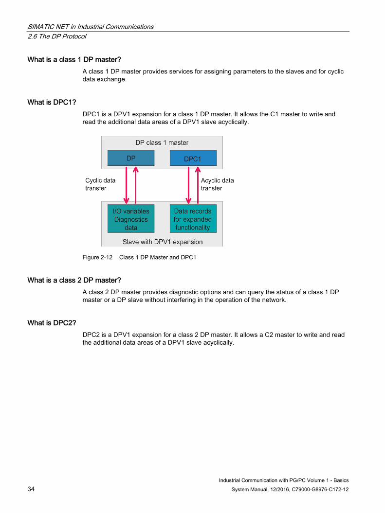
What is DPC1? DPC1 is a DPV1 expansion for a class 1 DP master. It allows the C1 master to write and read the additional data areas of a DPV1 slave acyclically.
Figure 2-12 Class 1 DP Master and DPC1
What is a class 2 DP master? A class 2 DP master provides diagnostic options and can query the status of a class 1 DP master or a DP slave without interfering in the operation of the network.
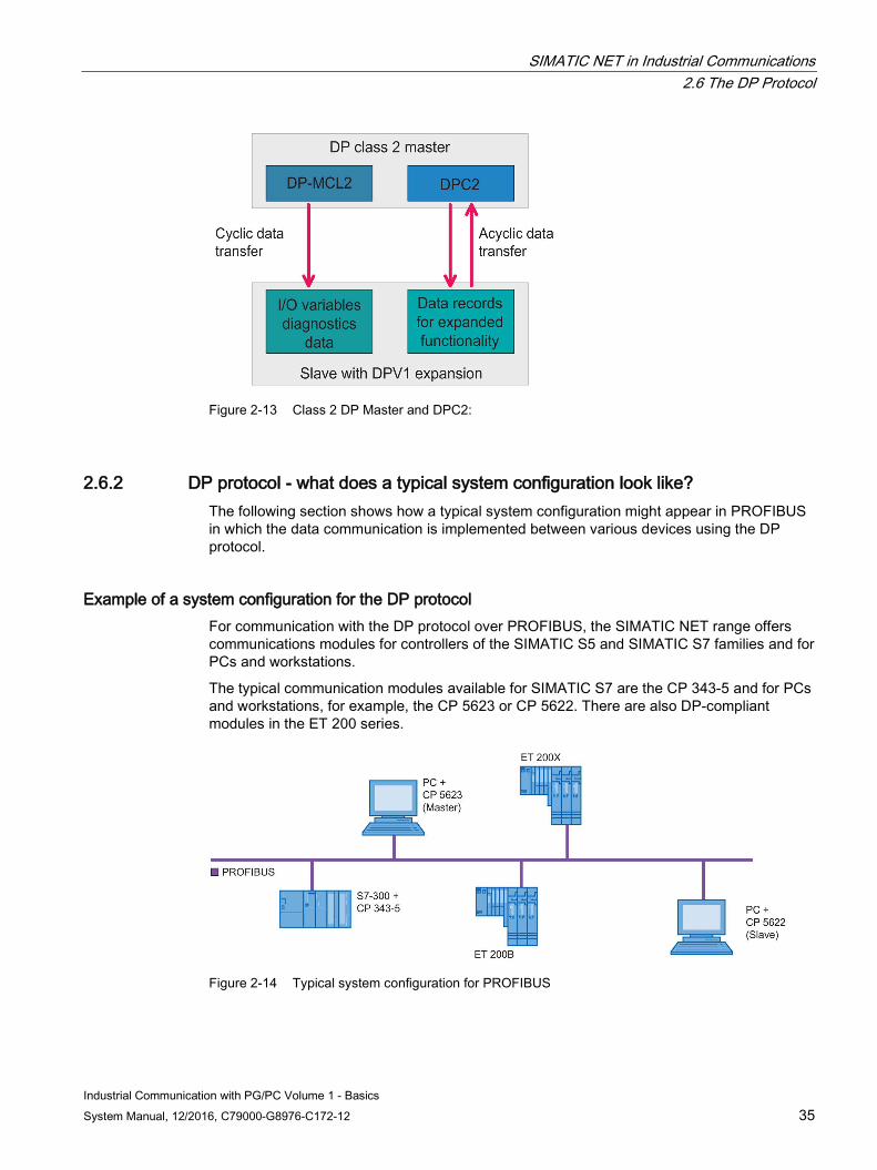
What is DPC2? DPC2 is a DPV1 expansion for a class 2 DP master. It allows a C2 master to write and read the additional data areas of a DPV1 slave acyclically.
SIMATIC NET in Industrial Communications 2.6 The DP Protocol
Industrial Communication with PG/PC Volume 1 - Basics System Manual, 12/2016, C79000-G8976-C172-12 35
Figure 2-13 Class 2 DP Master and DPC2:
2.6.2 DP protocol - what does a typical system configuration look like? The following section shows how a typical system configuration might appear in PROFIBUS in which the data communication is implemented between various devices using the DP protocol.
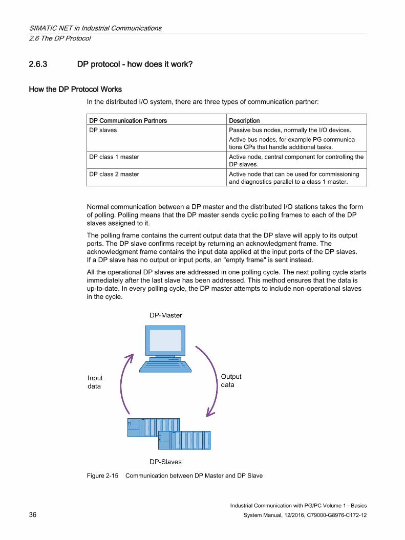
Example of a system configuration for the DP protocol For communication with the DP protocol over PROFIBUS, the SIMATIC NET range offers communications modules for controllers of the SIMATIC S5 and SIMATIC S7 families and for PCs and workstations.
The typical communication modules available for SIMATIC S7 are the CP 343-5 and for PCs and workstations, for example, the CP 5623 or CP 5622. There are also DP-compliant modules in the ET 200 series.
Figure 2-14 Typical system configuration for PROFIBUS
SIMATIC NET in Industrial Communications 2.6 The DP Protocol
Industrial Communication with PG/PC Volume 1 - Basics 36 System Manual, 12/2016, C79000-G8976-C172-12
2.6.3 DP protocol - how does it work?
How the DP Protocol Works In the distributed I/O system, there are three types of communication partner: DP Communication Partners Description DP slaves Passive bus nodes, normally the I/O devices.
Active bus nodes, for example PG communica-tions CPs that handle additional tasks.
DP class 1 master Active node, central component for controlling the DP slaves.
DP class 2 master Active node that can be used for commissioning and diagnostics parallel to a class 1 master.
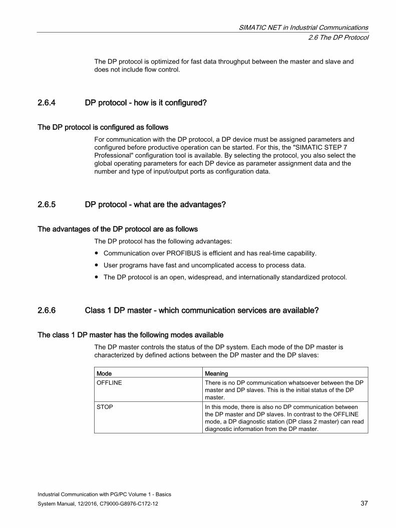
Normal communication between a DP master and the distributed I/O stations takes the form of polling. Polling means that the DP master sends cyclic polling frames to each of the DP slaves assigned to it.
The polling frame contains the current output data that the DP slave will apply to its output ports. The DP slave confirms receipt by returning an acknowledgment frame. The acknowledgment frame contains the input data applied at the input ports of the DP slaves. If a DP slave has no output or input ports, an "empty frame" is sent instead.
All the operational DP slaves are addressed in one polling cycle. The next polling cycle starts immediately after the last slave has been addressed. This method ensures that the data is up-to-date. In every polling cycle, the DP master attempts to include non-operational slaves in the cycle.
Figure 2-15 Communication between DP Master and DP Slave
SIMATIC NET in Industrial Communications 2.6 The DP Protocol
Industrial Communication with PG/PC Volume 1 - Basics System Manual, 12/2016, C79000-G8976-C172-12 37
The DP protocol is optimized for fast data throughput between the master and slave and does not include flow control.
2.6.4 DP protocol - how is it configured?
The DP protocol is configured as follows For communication with the DP protocol, a DP device must be assigned parameters and configured before productive operation can be started. For this, the "SIMATIC STEP 7 Professional" configuration tool is available. By selecting the protocol, you also select the global operating parameters for each DP device as parameter assignment data and the number and type of input/output ports as configuration data.
2.6.5 DP protocol - what are the advantages?
The advantages of the DP protocol are as follows The DP protocol has the following advantages:
● Communication over PROFIBUS is efficient and has real-time capability.
● User programs have fast and uncomplicated access to process data.
● The DP protocol is an open, widespread, and internationally standardized protocol.
2.6.6 Class 1 DP master - which communication services are available?
The class 1 DP master has the following modes available The DP master controls the status of the DP system. Each mode of the DP master is characterized by defined actions between the DP master and the DP slaves: Mode Meaning OFFLINE There is no DP communication whatsoever between the DP
master and DP slaves. This is the initial status of the DP master.
STOP In this mode, there is also no DP communication between the DP master and DP slaves. In contrast to the OFFLINE mode, a DP diagnostic station (DP class 2 master) can read diagnostic information from the DP master.
SIMATIC NET in Industrial Communications 2.6 The DP Protocol
Industrial Communication with PG/PC Volume 1 - Basics 38 System Manual, 12/2016, C79000-G8976-C172-12
Mode Meaning CLEAR The DP master supplies the DP slave with data that it re-
quires to start up (parameter assignment and configuration). Following this, the value 0h is sent to all slaves with process output in the CLEAR mode; in other words, process output is in a safe status. The input data of the slaves is known and can be read.
OPERATE There is cyclic data transfer between the DP master and DP slaves. This is known as the productive phase. In this mode, the DP slaves are polled one after the other by the DP mas-ter.
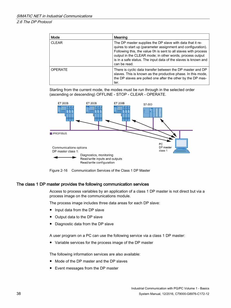
Starting from the current mode, the modes must be run through in the selected order (ascending or descending) OFFLINE - STOP - CLEAR - OPERATE.
Figure 2-16 Communication Services of the Class 1 DP Master
The class 1 DP master provides the following communication services Access to process variables by an application of a class 1 DP master is not direct but via a process image on the communications module.
The process image includes three data areas for each DP slave:
● Input data from the DP slave
● Output data to the DP slave
● Diagnostic data from the DP slave
A user program on a PC can use the following service via a class 1 DP master:
● Variable services for the process image of the DP master
The following information services are also available:
● Mode of the DP master and the DP slaves
● Event messages from the DP master

SIMATIC NET in Industrial Communications 2.6 The DP Protocol
Industrial Communication with PG/PC Volume 1 - Basics System Manual, 12/2016, C79000-G8976-C172-12 39
● Activity monitoring by the DP module
● The type of a DP slave
What are the advantages and disadvantages of the class 1 DP master? The use of a class 1 DP master has the following advantages:
● Fast access to cyclic data.
● Jobs from the applications can be processed extremely quickly because the data can be obtained directly from the process image and do not lead explicitly to communication.
The use of a class 1 DP master has the following disadvantage:
● High bus load due to the cyclic exchange of input and output data.
2.6.7 Class 2 DP master - which communication services are available?
How the Class 2 DP Master Works Alongside devices belonging to the class 1 DP master, a DP system can also include class 2 DP master devices. These are used for commissioning, configuration, or diagnostics. It is, for example, possible to connect a class 2 DP master to PROFIBUS for diagnostic purposes. This can then query the status of slaves and class 1 masters at any time without interfering with network operation. A class 2 DP master can also change the slave address if the slave permits this.
Figure 2-17 Communication Services of the Class 2 DP Master
SIMATIC NET in Industrial Communications 2.6 The DP Protocol
Industrial Communication with PG/PC Volume 1 - Basics 40 System Manual, 12/2016, C79000-G8976-C172-12
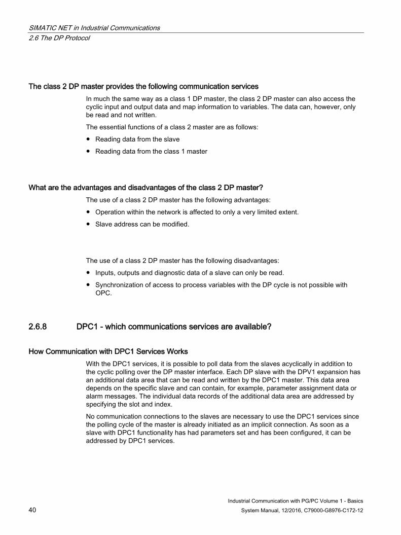
The class 2 DP master provides the following communication services In much the same way as a class 1 DP master, the class 2 DP master can also access the cyclic input and output data and map information to variables. The data can, however, only be read and not written.
The essential functions of a class 2 master are as follows:
● Reading data from the slave
● Reading data from the class 1 master
What are the advantages and disadvantages of the class 2 DP master? The use of a class 2 DP master has the following advantages:
● Operation within the network is affected to only a very limited extent.
● Slave address can be modified.
The use of a class 2 DP master has the following disadvantages:
● Inputs, outputs and diagnostic data of a slave can only be read.
● Synchronization of access to process variables with the DP cycle is not possible with OPC.
2.6.8 DPC1 - which communications services are available?
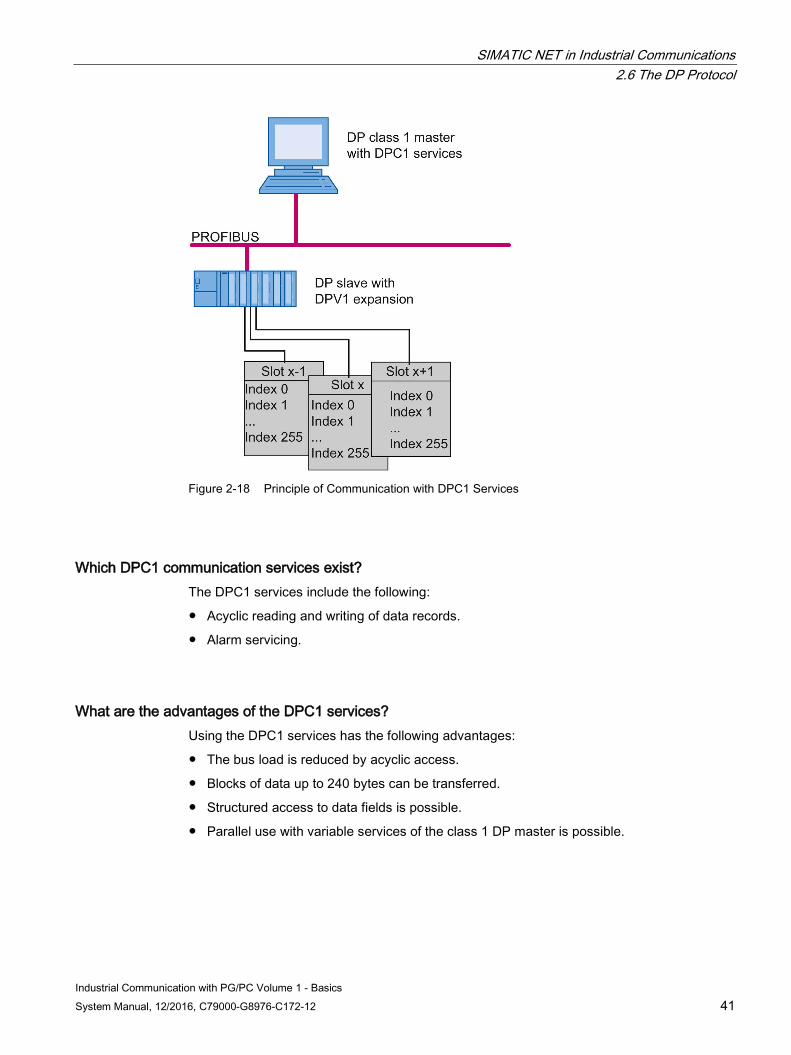
How Communication with DPC1 Services Works With the DPC1 services, it is possible to poll data from the slaves acyclically in addition to the cyclic polling over the DP master interface. Each DP slave with the DPV1 expansion has an additional data area that can be read and written by the DPC1 master. This data area depends on the specific slave and can contain, for example, parameter assignment data or alarm messages. The individual data records of the additional data area are addressed by specifying the slot and index.
No communication connections to the slaves are necessary to use the DPC1 services since the polling cycle of the master is already initiated as an implicit connection. As soon as a slave with DPC1 functionality has had parameters set and has been configured, it can be addressed by DPC1 services.
SIMATIC NET in Industrial Communications 2.6 The DP Protocol
Industrial Communication with PG/PC Volume 1 - Basics System Manual, 12/2016, C79000-G8976-C172-12 41
Figure 2-18 Principle of Communication with DPC1 Services
Which DPC1 communication services exist? The DPC1 services include the following:
● Acyclic reading and writing of data records.
● Alarm servicing.
What are the advantages of the DPC1 services? Using the DPC1 services has the following advantages:
● The bus load is reduced by acyclic access.
● Blocks of data up to 240 bytes can be transferred.
● Structured access to data fields is possible.
● Parallel use with variable services of the class 1 DP master is possible.
SIMATIC NET in Industrial Communications 2.6 The DP Protocol
Industrial Communication with PG/PC Volume 1 - Basics 42 System Manual, 12/2016, C79000-G8976-C172-12
2.6.9 DPC2 - which communications services are available?
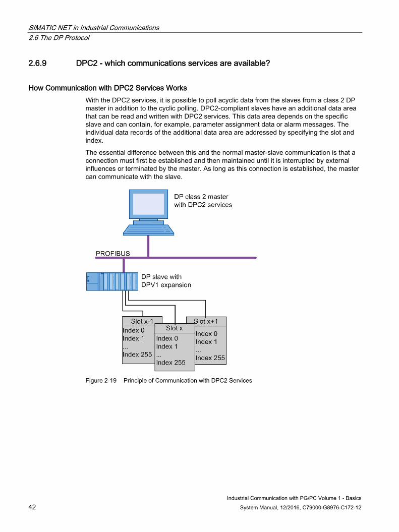
How Communication with DPC2 Services Works With the DPC2 services, it is possible to poll acyclic data from the slaves from a class 2 DP master in addition to the cyclic polling. DPC2-compliant slaves have an additional data area that can be read and written with DPC2 services. This data area depends on the specific slave and can contain, for example, parameter assignment data or alarm messages. The individual data records of the additional data area are addressed by specifying the slot and index.
The essential difference between this and the normal master-slave communication is that a connection must first be established and then maintained until it is interrupted by external influences or terminated by the master. As long as this connection is established, the master can communicate with the slave.
Figure 2-19 Principle of Communication with DPC2 Services
SIMATIC NET in Industrial Communications 2.6 The DP Protocol
Industrial Communication with PG/PC Volume 1 - Basics System Manual, 12/2016, C79000-G8976-C172-12 43
Which DPC2 communication services exist? The most important DPC2 services are as follows:
● Establishment and termination of a communication relation
● Reading the slave data records
The use of DPC2 services provides the user with buffer send/receive services.
Since the DPC2 services are handled with lower priority than the cyclic data services, the data throughput is lower. The round-trip time is also generally increased since the network is under additional load.
In the same way as a class 1 DP master (DPC1), a class 2 master can only access the data of a DPV1 slot as an entire block. A read job returns the entire contents of a data record identified by the slot and index, a write job overwrites the entire data record.
What are the advantages of the DPC2 services? Using the DPC2 services has the following advantages:
● Asynchronous access to slaves is possible.
● Larger blocks of data can be transferred.
● Structured access to data fields is possible.
● Parallel use with a class 1 master is possible.
2.6.10 DP slave - which communications services are available?
A DP slave provides the following communication services A DP slave provides data communication services that allow a DP master to fetch input data over PROFIBUS during a polling cycle and to receive and process output data sent by the DP master. The DP slave can also set diagnostic data that can be read by the DP master.
Within DP communication, DP slaves are considered to be modular. Each slave can be made up of several submodules each with their own input and output areas.
A slave suitable for the DPV1 expansion can contain additional data records for each module. These data records contain slave-specific data that can be read and written by a DPC1 master. Up to 240 bytes of payload data are available per data record.
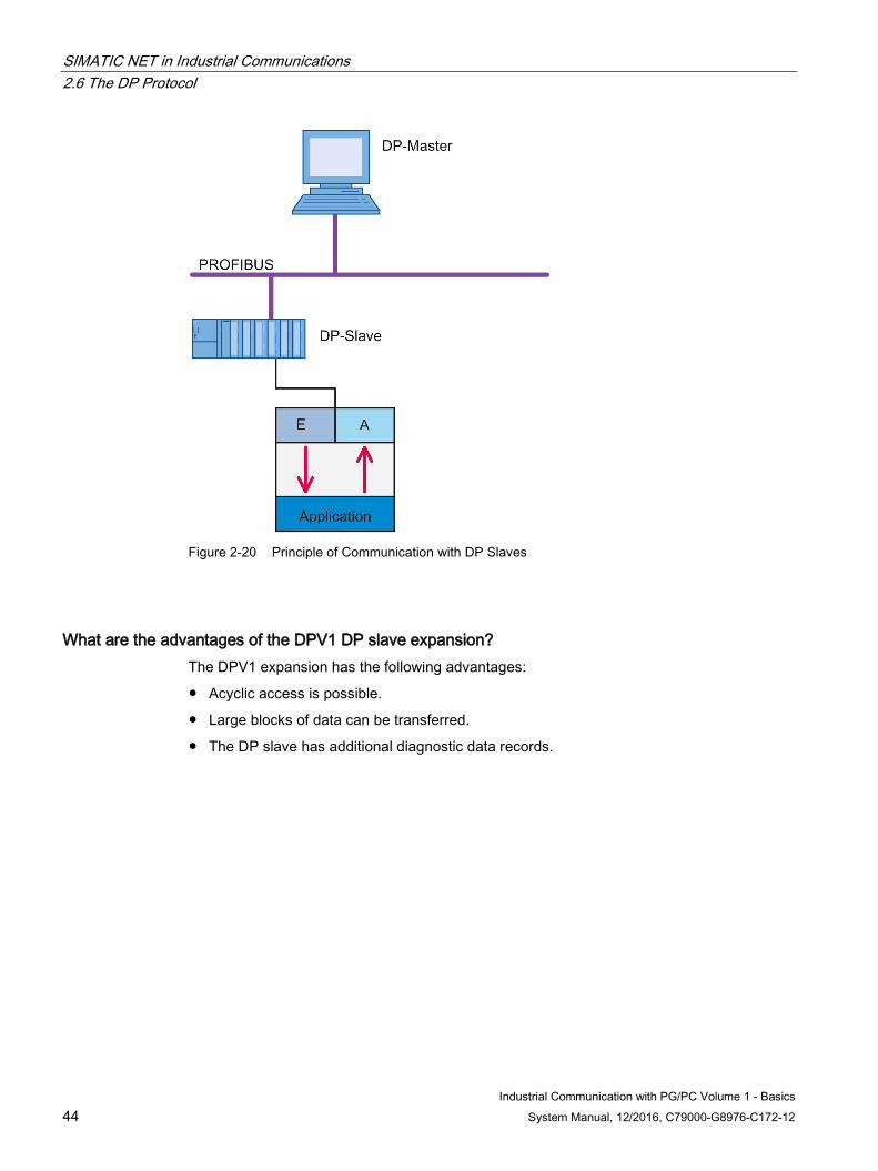
SIMATIC NET in Industrial Communications 2.6 The DP Protocol
Industrial Communication with PG/PC Volume 1 - Basics 44 System Manual, 12/2016, C79000-G8976-C172-12
Figure 2-20 Principle of Communication with DP Slaves
What are the advantages of the DPV1 DP slave expansion? The DPV1 expansion has the following advantages:
● Acyclic access is possible.
● Large blocks of data can be transferred.
● The DP slave has additional diagnostic data records.
SIMATIC NET in Industrial Communications 2.7 The S7 Protocol
Industrial Communication with PG/PC Volume 1 - Basics System Manual, 12/2016, C79000-G8976-C172-12 45
2.7 The S7 Protocol
2.7.1 S7 protocol - what is it?
The S7 Protocol The S7 protocol is used for communication with SIMATIC S7 programmable controllers (PLCs). It supports both communication between PG/PC and programmable controllers as well as data exchange between programmable controllers of the SIMATIC S7 system.
What are the properties of the S7 protocol? The main features of the S7 protocol are as follows:
● Optimized for SIMATIC communication
● Greater speed compared with other automation protocols for data communication.
● Availability for bus systems of the management and cell level with Industrial Ethernet and the field level with PROFIBUS.
● Can also be used with fault-tolerant connections.
What are the differences between the S7 protocol for PROFIBUS and for Ethernet? In PROFIBUS, the S7 protocol is based on the FDL services, while in Ethernet, it uses the available services of the transport layer. This difference is hidden by the S7 protocol so that the user is not aware of any differences in communication.
What are the common features of the S7 protocol in PROFIBUS and in Ethernet? With both communication systems, the S7 protocol provides the advantages of a connection-oriented protocol, for example, connection monitoring. All the communication services implemented in the S7 protocol are also available without restrictions.
2.7.2 S7 protocol - what does a typical system configuration look like? This section illustrates typical system configurations in PROFIBUS and Industrial Ethernet in which data communication between different devices is implemented with the S7 protocol.
Example of a system configuration for the S7 protocol in PROFIBUS For communication with the S7 protocol over PROFIBUS, the SIMATIC NET range offers communications modules for controllers of the SIMATIC S7 family and for PCs and workstations.
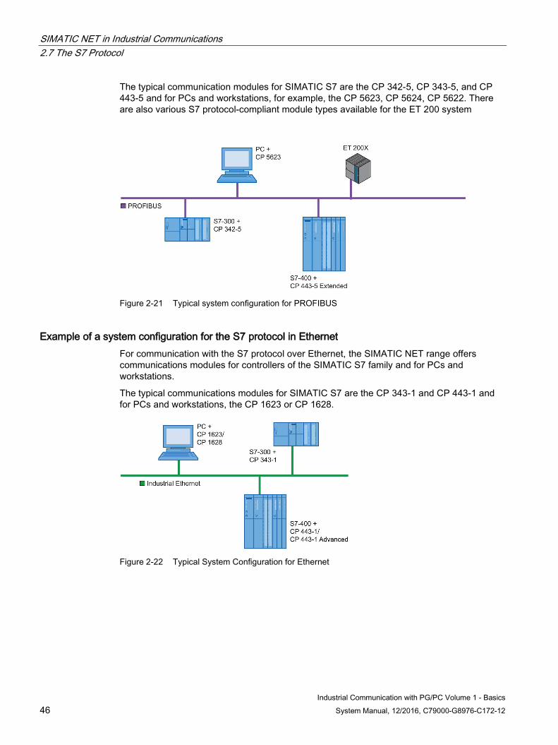
SIMATIC NET in Industrial Communications 2.7 The S7 Protocol
Industrial Communication with PG/PC Volume 1 - Basics 46 System Manual, 12/2016, C79000-G8976-C172-12
The typical communication modules for SIMATIC S7 are the CP 342-5, CP 343-5, and CP 443-5 and for PCs and workstations, for example, the CP 5623, CP 5624, CP 5622. There are also various S7 protocol-compliant module types available for the ET 200 system
Figure 2-21 Typical system configuration for PROFIBUS
Example of a system configuration for the S7 protocol in Ethernet For communication with the S7 protocol over Ethernet, the SIMATIC NET range offers communications modules for controllers of the SIMATIC S7 family and for PCs and workstations.
The typical communications modules for SIMATIC S7 are the CP 343-1 and CP 443-1 and for PCs and workstations, the CP 1623 or CP 1628.
Figure 2-22 Typical System Configuration for Ethernet
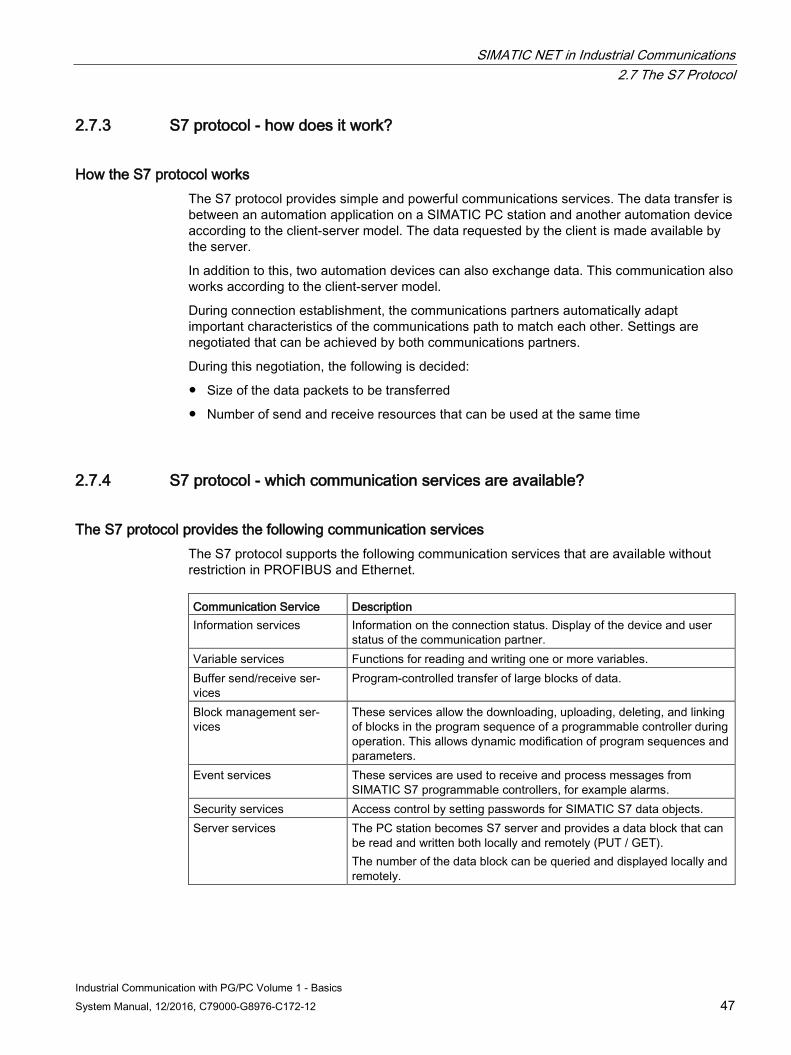
SIMATIC NET in Industrial Communications 2.7 The S7 Protocol
Industrial Communication with PG/PC Volume 1 - Basics System Manual, 12/2016, C79000-G8976-C172-12 47
2.7.3 S7 protocol - how does it work?
How the S7 protocol works The S7 protocol provides simple and powerful communications services. The data transfer is between an automation application on a SIMATIC PC station and another automation device according to the client-server model. The data requested by the client is made available by the server.
In addition to this, two automation devices can also exchange data. This communication also works according to the client-server model.
During connection establishment, the communications partners automatically adapt important characteristics of the communications path to match each other. Settings are negotiated that can be achieved by both communications partners.
During this negotiation, the following is decided:
● Size of the data packets to be transferred
● Number of send and receive resources that can be used at the same time
2.7.4 S7 protocol - which communication services are available?
The S7 protocol provides the following communication services The S7 protocol supports the following communication services that are available without restriction in PROFIBUS and Ethernet. Communication Service Description Information services Information on the connection status. Display of the device and user
status of the communication partner. Variable services Functions for reading and writing one or more variables. Buffer send/receive ser-vices
Program-controlled transfer of large blocks of data.
Block management ser-vices
These services allow the downloading, uploading, deleting, and linking of blocks in the program sequence of a programmable controller during operation. This allows dynamic modification of program sequences and parameters.
Event services These services are used to receive and process messages from SIMATIC S7 programmable controllers, for example alarms.
Security services Access control by setting passwords for SIMATIC S7 data objects. Server services The PC station becomes S7 server and provides a data block that can
be read and written both locally and remotely (PUT / GET). The number of the data block can be queried and displayed locally and remotely.
SIMATIC NET in Industrial Communications 2.7 The S7 Protocol
Industrial Communication with PG/PC Volume 1 - Basics 48 System Manual, 12/2016, C79000-G8976-C172-12
What can the S7 information services do? The S7 protocol provides information services with which
● attributes of a partner device can be queried.
● the status of a partner device can be read.
What can the S7 variable services do? The S7 protocol allows simple access to S7 variables.
The following S7 variables are available on most S7 devices:
● Data blocks
● Instance data blocks
● Inputs/outputs
● Peripheral inputs/outputs
● Memory bits
● Timers
● Counters
What are the advantages and disadvantages of the S7 variable services? Using the variable services has the following advantages:
● Very simple access to the partner device without programming the partner.
● Reading and writing several variables and long arrays of variables is optimized.
● When using the OPC server, access rights can be assigned to protect safety-related variables.
● With OPC, it is possible to use symbols from STEP 7.
● When using OPC, the size of variables and the size of a block of data are restricted to a maximum of 64 Kbytes.
Using the variable services has the following disadvantages:
● To monitor variable changes, the partner device must be accessed cyclically.
● Access at short intervals means a high network load.
What can the S7 buffer send/receive services do? The S7 buffer send/receive services allow programcontrolled transfer of larger blocks of data. Up to 65534 bytes of data can be transferred.
Before data can be exchanged, a connection must be configured. This applies to connections both between the PC and programmable controller and between programmable controllers.
SIMATIC NET in Industrial Communications 2.7 The S7 Protocol
Industrial Communication with PG/PC Volume 1 - Basics System Manual, 12/2016, C79000-G8976-C172-12 49
What are the advantages and disadvantages of the S7 buffer send/receive services? Using the S7 buffer send/receive services has the following advantages:
● Large (max. 65534 bytes) blocks of data can also be transferred.
● A SIMATIC PC can be both client and server, in other words, with buffer send/receive services, data can also be transferred from PC to PC using the S7 protocol.
● It is possible to structure the blocks of data in OPC items.
● All OPC variables defined within a receive buffer receive a change message when a block of data arrives and the relevant data has changed.
● There is no network load from polling if no data is sent.
Using the buffer-oriented services has the following disadvantages:
● Send and receive blocks must be programmed on the programmable controllers and, when applicable, on the PC.
● The receiver cannot request data but must wait until data is sent.
● Buffer send/receive services are not available for all S7 programmable controllers.
What can the S7 block management services do? The S7 block management service with the S7 protocol provides the following applications:
● Downloading data from the PG/PC to the SIMATIC CPU.
● Uploading data from the SIMATIC CPU to the PG/PC.
● Linking of blocks in the program sequence of the SIMATIC CPU.
● Deleting blocks.
● Compressing the memory on the programmable controller.
A block represents a loadable area on a programmable controller. The block management services can be used with organization blocks (OB), function blocks (FB), functions (FC), data blocks (DB), and system data blocks (SDB).
A block can, for example, be uploaded from an S7 CPU to a PC by an S7-OPC application and vice versa. On the PC, the blocks are stored in files. The block name is unique within the S7-CPU. The maximum amount of data is limited depending on the specific CPU. The blocks are therefore divided into separate segments that are transferred sequentially.
A block transferred to a programmable controller is stored in a buffer. This means that the block is not yet available for an S7 program. Although the block is visible in the list of data blocks that can be viewed using the online functions of STEP 7, the block cannot be opened. This is only possible after the block has been linked into the list of active blocks.
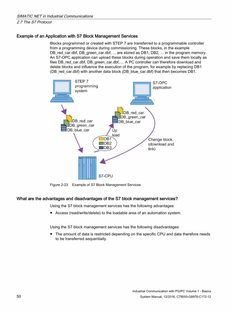
SIMATIC NET in Industrial Communications 2.7 The S7 Protocol
Industrial Communication with PG/PC Volume 1 - Basics 50 System Manual, 12/2016, C79000-G8976-C172-12
Example of an Application with S7 Block Management Services Blocks programmed or created with STEP 7 are transferred to a programmable controller from a programming device during commissioning. These blocks, in the example DB_red_car.dbf, DB_green_car.dbf, ... are stored as DB1, DB2, ... in the program memory. An S7-OPC application can upload these blocks during operation and save them locally as files DB_red_car.dbf, DB_green_car.dbf,.... A PC controller can therefore download and delete blocks and influence the execution of the program, for example by replacing DB1 (DB_red_car.dbf) with another data block (DB_blue_car.dbf) that then becomes DB1.
Figure 2-23 Example of S7 Block Management Services
What are the advantages and disadvantages of the S7 block management services? Using the S7 block management services has the following advantages:
● Access (read/write/delete) to the loadable area of an automation system.
Using the S7 block management services has the following disadvantages:
● The amount of data is restricted depending on the specific CPU and data therefore needs to be transferred sequentially.
SIMATIC NET in Industrial Communications 2.7 The S7 Protocol
Industrial Communication with PG/PC Volume 1 - Basics System Manual, 12/2016, C79000-G8976-C172-12 51
What can the S7 alarm service do? The S7 alarm service allows the alarms of a programmable controller to be received. Using the service, for example, disturbances and problems can be signaled.
For detailed display of alarms on the PC, they can be sent along with up to 10 associated values. Alarms are exceptional events and are triggered by the programmable controller. They are buffered and cannot be lost.
What are the advantages and disadvantages of the S7 alarm service? Using the S7 alarm service has the following advantages:
● Messages are buffered and cannot be lost.
● Up to 10 associated values can be transferred with an alarm.
The use of the S7 alarm services has the following disadvantages:
● A program must be created on the controller to generate the messages.
● Only a limited number of data types are supported for associated values.
What can the S7 security service do? The S7 security service regulates access to S7 connections. This allows transfer of a password for legitimization and therefore canceling of a level of protection on a connection.
Three levels of protection can be activated for the block management services with an S7 automation system using the STEP 7 configuration tool:
● Protection based on the keyswitch setting
● Write protection
● Write and read protection
By transferring the correct password, all the levels of protection above can be canceled for the current connection.
What are the advantages of the S7 security service? The use of the S7 security services has the following advantages:
● Access control for connections
● Access control by the keyswitch can be canceled
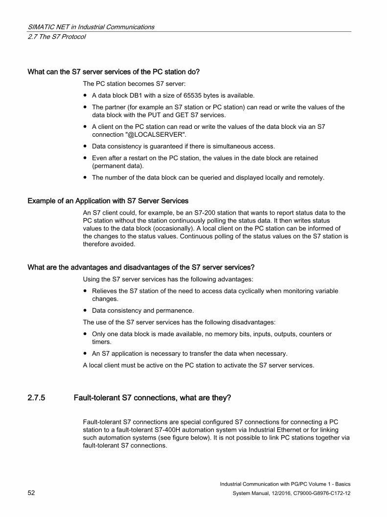
SIMATIC NET in Industrial Communications 2.7 The S7 Protocol
Industrial Communication with PG/PC Volume 1 - Basics 52 System Manual, 12/2016, C79000-G8976-C172-12
What can the S7 server services of the PC station do? The PC station becomes S7 server:
● A data block DB1 with a size of 65535 bytes is available.
● The partner (for example an S7 station or PC station) can read or write the values of the data block with the PUT and GET S7 services.
● A client on the PC station can read or write the values of the data block via an S7 connection "@LOCALSERVER".
● Data consistency is guaranteed if there is simultaneous access.
● Even after a restart on the PC station, the values in the date block are retained (permanent data).
● The number of the data block can be queried and displayed locally and remotely.
Example of an Application with S7 Server Services An S7 client could, for example, be an S7-200 station that wants to report status data to the PC station without the station continuously polling the status data. It then writes status values to the data block (occasionally). A local client on the PC station can be informed of the changes to the status values. Continuous polling of the status values on the S7 station is therefore avoided.
What are the advantages and disadvantages of the S7 server services? Using the S7 server services has the following advantages:
● Relieves the S7 station of the need to access data cyclically when monitoring variable changes.
● Data consistency and permanence.
The use of the S7 server services has the following disadvantages:
● Only one data block is made available, no memory bits, inputs, outputs, counters or timers.
● An S7 application is necessary to transfer the data when necessary.
A local client must be active on the PC station to activate the S7 server services.
2.7.5 Fault-tolerant S7 connections, what are they?
Fault-tolerant S7 connections are special configured S7 connections for connecting a PC station to a fault-tolerant S7-400H automation system via Industrial Ethernet or for linking such automation systems (see figure below). It is not possible to link PC stations together via fault-tolerant S7 connections.
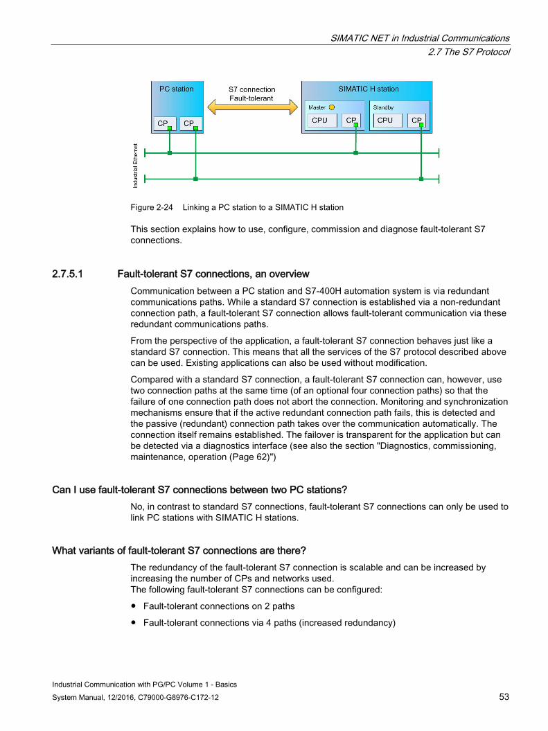
SIMATIC NET in Industrial Communications 2.7 The S7 Protocol
Industrial Communication with PG/PC Volume 1 - Basics System Manual, 12/2016, C79000-G8976-C172-12 53
Figure 2-24 Linking a PC station to a SIMATIC H station
This section explains how to use, configure, commission and diagnose fault-tolerant S7 connections.
2.7.5.1 Fault-tolerant S7 connections, an overview Communication between a PC station and S7-400H automation system is via redundant communications paths. While a standard S7 connection is established via a non-redundant connection path, a fault-tolerant S7 connection allows fault-tolerant communication via these redundant communications paths.
From the perspective of the application, a fault-tolerant S7 connection behaves just like a standard S7 connection. This means that all the services of the S7 protocol described above can be used. Existing applications can also be used without modification.
Compared with a standard S7 connection, a fault-tolerant S7 connection can, however, use two connection paths at the same time (of an optional four connection paths) so that the failure of one connection path does not abort the connection. Monitoring and synchronization mechanisms ensure that if the active redundant connection path fails, this is detected and the passive (redundant) connection path takes over the communication automatically. The connection itself remains established. The failover is transparent for the application but can be detected via a diagnostics interface (see also the section "Diagnostics, commissioning, maintenance, operation (Page 62)")
Can I use fault-tolerant S7 connections between two PC stations? No, in contrast to standard S7 connections, fault-tolerant S7 connections can only be used to link PC stations with SIMATIC H stations.
What variants of fault-tolerant S7 connections are there? The redundancy of the fault-tolerant S7 connection is scalable and can be increased by increasing the number of CPs and networks used. The following fault-tolerant S7 connections can be configured:
● Fault-tolerant connections on 2 paths
● Fault-tolerant connections via 4 paths (increased redundancy)
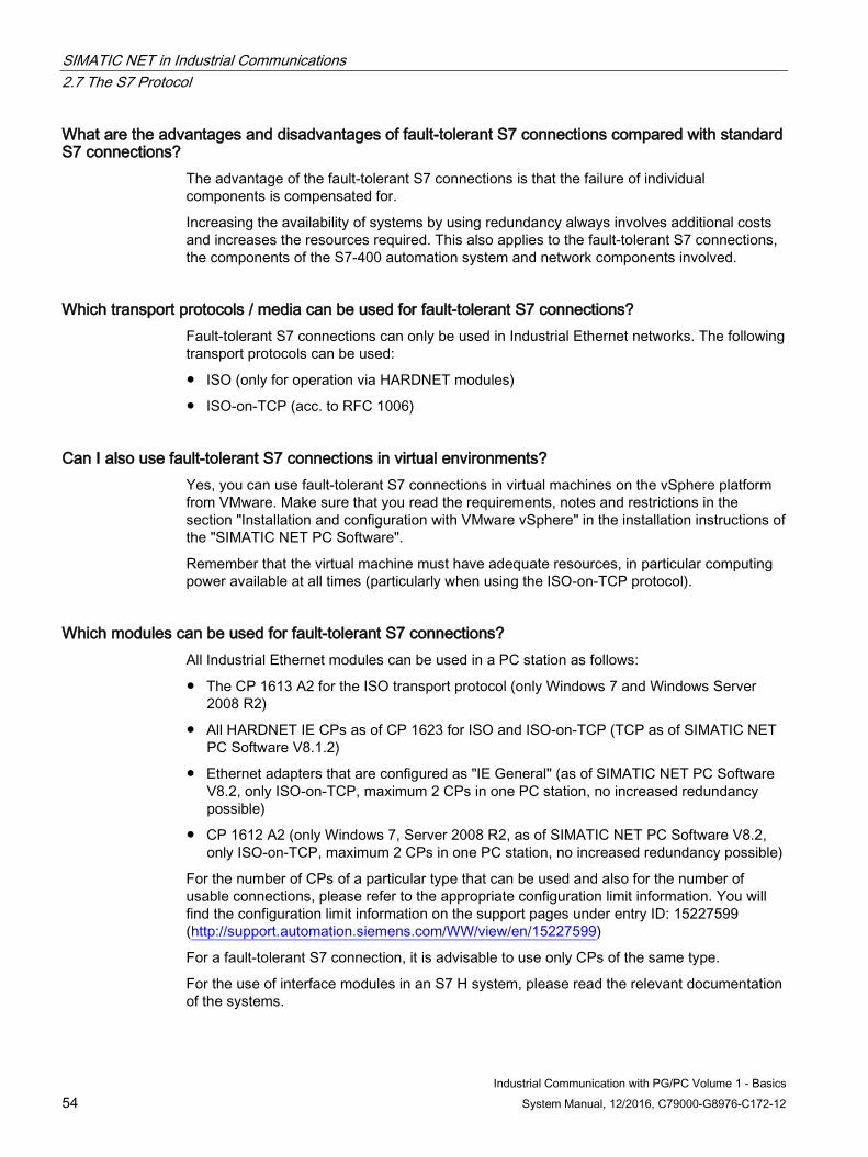
SIMATIC NET in Industrial Communications 2.7 The S7 Protocol
Industrial Communication with PG/PC Volume 1 - Basics 54 System Manual, 12/2016, C79000-G8976-C172-12
What are the advantages and disadvantages of fault-tolerant S7 connections compared with standard S7 connections?
The advantage of the fault-tolerant S7 connections is that the failure of individual components is compensated for.
Increasing the availability of systems by using redundancy always involves additional costs and increases the resources required. This also applies to the fault-tolerant S7 connections, the components of the S7-400 automation system and network components involved.
Which transport protocols / media can be used for fault-tolerant S7 connections? Fault-tolerant S7 connections can only be used in Industrial Ethernet networks. The following transport protocols can be used:
● ISO (only for operation via HARDNET modules)
● ISO-on-TCP (acc. to RFC 1006)
Can I also use fault-tolerant S7 connections in virtual environments? Yes, you can use fault-tolerant S7 connections in virtual machines on the vSphere platform from VMware. Make sure that you read the requirements, notes and restrictions in the section "Installation and configuration with VMware vSphere" in the installation instructions of the "SIMATIC NET PC Software".
Remember that the virtual machine must have adequate resources, in particular computing power available at all times (particularly when using the ISO-on-TCP protocol).
Which modules can be used for fault-tolerant S7 connections? All Industrial Ethernet modules can be used in a PC station as follows:
● The CP 1613 A2 for the ISO transport protocol (only Windows 7 and Windows Server 2008 R2)
● All HARDNET IE CPs as of CP 1623 for ISO and ISO-on-TCP (TCP as of SIMATIC NET PC Software V8.1.2)
● Ethernet adapters that are configured as "IE General" (as of SIMATIC NET PC Software V8.2, only ISO-on-TCP, maximum 2 CPs in one PC station, no increased redundancy possible)
● CP 1612 A2 (only Windows 7, Server 2008 R2, as of SIMATIC NET PC Software V8.2, only ISO-on-TCP, maximum 2 CPs in one PC station, no increased redundancy possible)
For the number of CPs of a particular type that can be used and also for the number of usable connections, please refer to the appropriate configuration limit information. You will find the configuration limit information on the support pages under entry ID: 15227599 (http://support.automation.siemens.com/WW/view/en/15227599)
For a fault-tolerant S7 connection, it is advisable to use only CPs of the same type.
For the use of interface modules in an S7 H system, please read the relevant documentation of the systems.
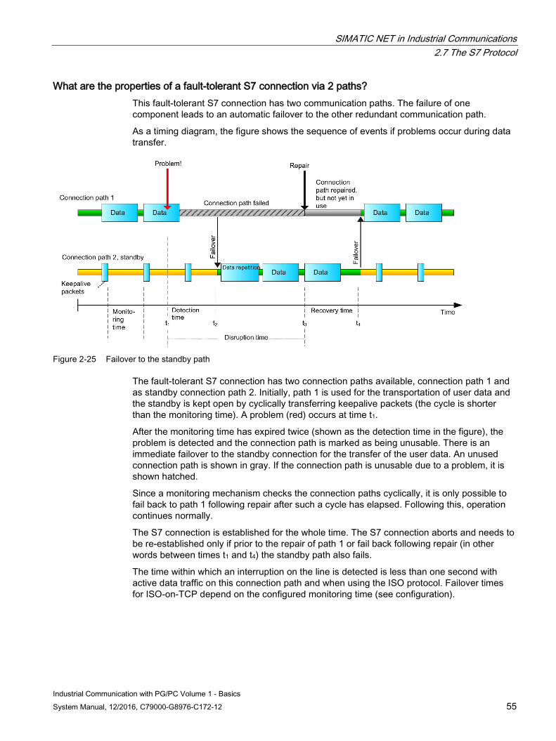
SIMATIC NET in Industrial Communications 2.7 The S7 Protocol
Industrial Communication with PG/PC Volume 1 - Basics System Manual, 12/2016, C79000-G8976-C172-12 55
What are the properties of a fault-tolerant S7 connection via 2 paths? This fault-tolerant S7 connection has two communication paths. The failure of one component leads to an automatic failover to the other redundant communication path.
As a timing diagram, the figure shows the sequence of events if problems occur during data transfer.
Figure 2-25 Failover to the standby path
The fault-tolerant S7 connection has two connection paths available, connection path 1 and as standby connection path 2. Initially, path 1 is used for the transportation of user data and the standby is kept open by cyclically transferring keepalive packets (the cycle is shorter than the monitoring time). A problem (red) occurs at time t1.
After the monitoring time has expired twice (shown as the detection time in the figure), the problem is detected and the connection path is marked as being unusable. There is an immediate failover to the standby connection for the transfer of the user data. An unused connection path is shown in gray. If the connection path is unusable due to a problem, it is shown hatched.
Since a monitoring mechanism checks the connection paths cyclically, it is only possible to fail back to path 1 following repair after such a cycle has elapsed. Following this, operation continues normally.
The S7 connection is established for the whole time. The S7 connection aborts and needs to be re-established only if prior to the repair of path 1 or fail back following repair (in other words between times t1 and t4) the standby path also fails.
The time within which an interruption on the line is detected is less than one second with active data traffic on this connection path and when using the ISO protocol. Failover times for ISO-on-TCP depend on the configured monitoring time (see configuration).
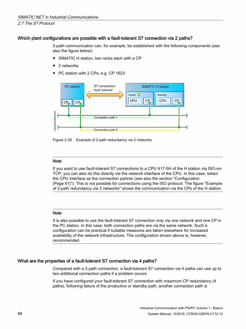
SIMATIC NET in Industrial Communications 2.7 The S7 Protocol
Industrial Communication with PG/PC Volume 1 - Basics 56 System Manual, 12/2016, C79000-G8976-C172-12
Which plant configurations are possible with a fault-tolerant S7 connection via 2 paths? 2-path communication can, for example, be established with the following components (see also the figure below):
● SIMATIC H station, two racks each with a CP
● 2 networks
● PC station with 2 CPs, e.g. CP 1623
Figure 2-26 Example of 2-path redundancy via 2 networks
Note
If you want to use fault-tolerant S7 connections to a CPU 417-5H of the H station via ISO-on-TCP, you can also do this directly via the network interface of the CPU. In this case, select the CPU interface as the connection partner (see also the section "Configuration (Page 61)"). This is not possible for connections using the ISO protocol. The figure "Example of 2-path redundancy via 2 networks" shows the communication via the CPs of the H station.
Note
It is also possible to use the fault-tolerant S7 connection only via one network and one CP in the PC station. In this case, both connection paths are via the same network. Such a configuration can be practical if suitable measures are taken elsewhere for increased availability of the network infrastructure. The configuration shown above is, however, recommended.
What are the properties of a fault-tolerant S7 connection via 4 paths? Compared with a 2-path connection, a fault-tolerant S7 connection via 4 paths can use up to two additional connection paths if a problem occurs.
If you have configured your fault-tolerant S7 connection with maximum CP redundancy (4 paths), following failure of the productive or standby path, another connection path is
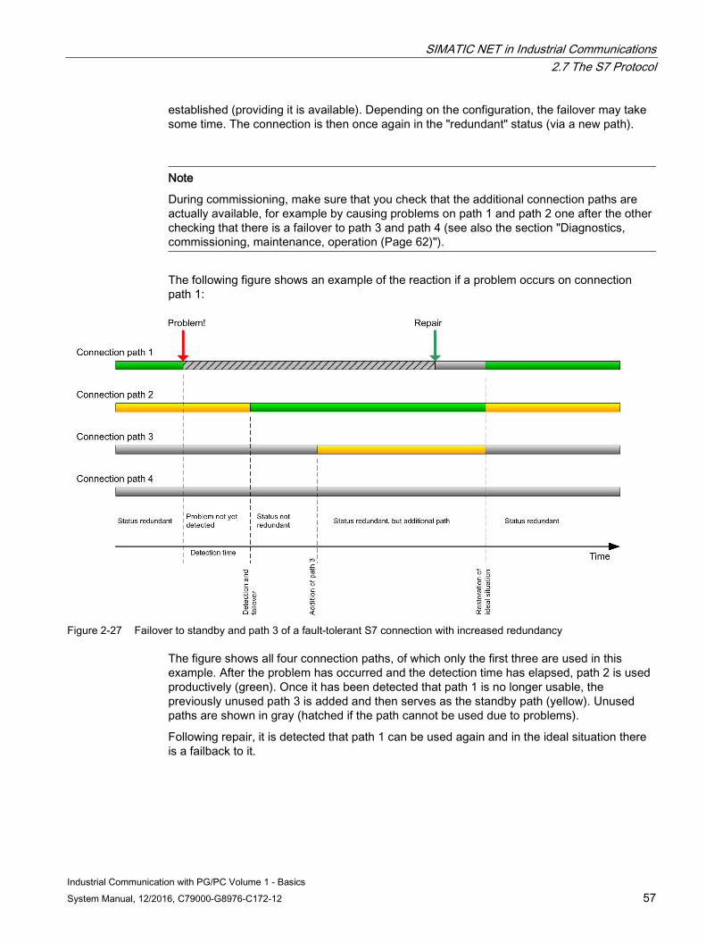
SIMATIC NET in Industrial Communications 2.7 The S7 Protocol
Industrial Communication with PG/PC Volume 1 - Basics System Manual, 12/2016, C79000-G8976-C172-12 57
established (providing it is available). Depending on the configuration, the failover may take some time. The connection is then once again in the "redundant" status (via a new path).
Note
During commissioning, make sure that you check that the additional connection paths are actually available, for example by causing problems on path 1 and path 2 one after the other checking that there is a failover to path 3 and path 4 (see also the section "Diagnostics, commissioning, maintenance, operation (Page 62)").
The following figure shows an example of the reaction if a problem occurs on connection path 1:
Figure 2-27 Failover to standby and path 3 of a fault-tolerant S7 connection with increased redundancy
The figure shows all four connection paths, of which only the first three are used in this example. After the problem has occurred and the detection time has elapsed, path 2 is used productively (green). Once it has been detected that path 1 is no longer usable, the previously unused path 3 is added and then serves as the standby path (yellow). Unused paths are shown in gray (hatched if the path cannot be used due to problems).
Following repair, it is detected that path 1 can be used again and in the ideal situation there is a failback to it.
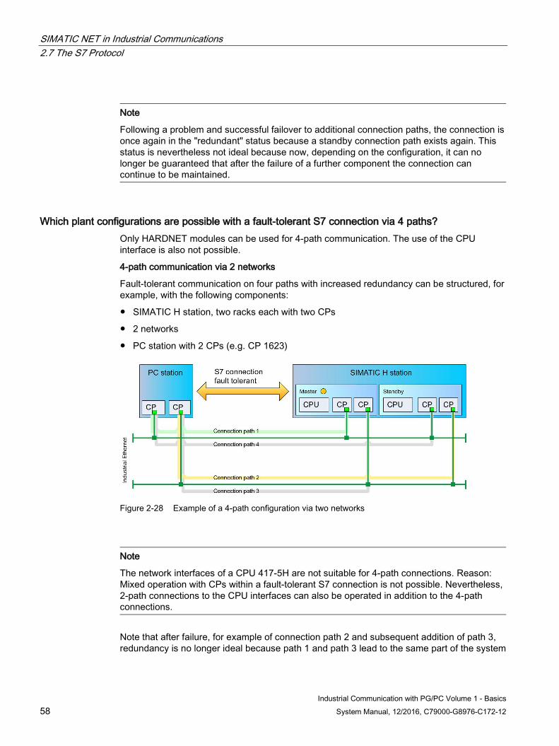
SIMATIC NET in Industrial Communications 2.7 The S7 Protocol
Industrial Communication with PG/PC Volume 1 - Basics 58 System Manual, 12/2016, C79000-G8976-C172-12
Note
Following a problem and successful failover to additional connection paths, the connection is once again in the "redundant" status because a standby connection path exists again. This status is nevertheless not ideal because now, depending on the configuration, it can no longer be guaranteed that after the failure of a further component the connection can continue to be maintained.
Which plant configurations are possible with a fault-tolerant S7 connection via 4 paths? Only HARDNET modules can be used for 4-path communication. The use of the CPU interface is also not possible.
4-path communication via 2 networks
Fault-tolerant communication on four paths with increased redundancy can be structured, for example, with the following components:
● SIMATIC H station, two racks each with two CPs
● 2 networks
● PC station with 2 CPs (e.g. CP 1623)
Figure 2-28 Example of a 4-path configuration via two networks
Note
The network interfaces of a CPU 417-5H are not suitable for 4-path connections. Reason: Mixed operation with CPs within a fault-tolerant S7 connection is not possible. Nevertheless, 2-path connections to the CPU interfaces can also be operated in addition to the 4-path connections.
Note that after failure, for example of connection path 2 and subsequent addition of path 3, redundancy is no longer ideal because path 1 and path 3 lead to the same part of the system
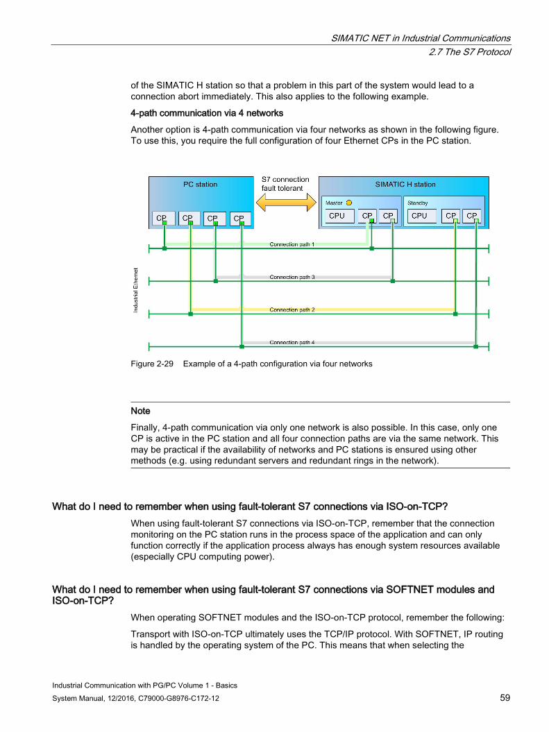
SIMATIC NET in Industrial Communications 2.7 The S7 Protocol
Industrial Communication with PG/PC Volume 1 - Basics System Manual, 12/2016, C79000-G8976-C172-12 59
of the SIMATIC H station so that a problem in this part of the system would lead to a connection abort immediately. This also applies to the following example.
4-path communication via 4 networks
Another option is 4-path communication via four networks as shown in the following figure. To use this, you require the full configuration of four Ethernet CPs in the PC station.
Figure 2-29 Example of a 4-path configuration via four networks
Note
Finally, 4-path communication via only one network is also possible. In this case, only one CP is active in the PC station and all four connection paths are via the same network. This may be practical if the availability of networks and PC stations is ensured using other methods (e.g. using redundant servers and redundant rings in the network).
What do I need to remember when using fault-tolerant S7 connections via ISO-on-TCP? When using fault-tolerant S7 connections via ISO-on-TCP, remember that the connection monitoring on the PC station runs in the process space of the application and can only function correctly if the application process always has enough system resources available (especially CPU computing power).
What do I need to remember when using fault-tolerant S7 connections via SOFTNET modules and ISO-on-TCP?
When operating SOFTNET modules and the ISO-on-TCP protocol, remember the following:
Transport with ISO-on-TCP ultimately uses the TCP/IP protocol. With SOFTNET, IP routing is handled by the operating system of the PC. This means that when selecting the
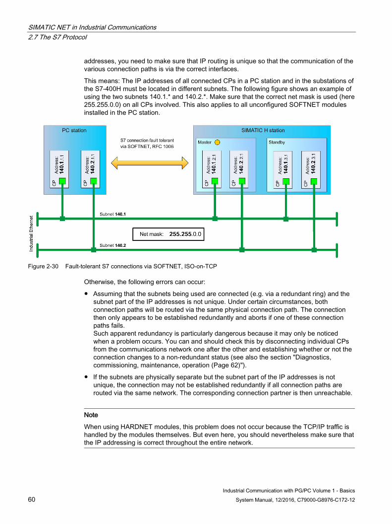
SIMATIC NET in Industrial Communications 2.7 The S7 Protocol
Industrial Communication with PG/PC Volume 1 - Basics 60 System Manual, 12/2016, C79000-G8976-C172-12
addresses, you need to make sure that IP routing is unique so that the communication of the various connection paths is via the correct interfaces.
This means: The IP addresses of all connected CPs in a PC station and in the substations of the S7-400H must be located in different subnets. The following figure shows an example of using the two subnets 140.1.* and 140.2.*. Make sure that the correct net mask is used (here 255.255.0.0) on all CPs involved. This also applies to all unconfigured SOFTNET modules installed in the PC station.
Figure 2-30 Fault-tolerant S7 connections via SOFTNET, ISO-on-TCP
Otherwise, the following errors can occur:
● Assuming that the subnets being used are connected (e.g. via a redundant ring) and the subnet part of the IP addresses is not unique. Under certain circumstances, both connection paths will be routed via the same physical connection path. The connection then only appears to be established redundantly and aborts if one of these connection paths fails. Such apparent redundancy is particularly dangerous because it may only be noticed when a problem occurs. You can and should check this by disconnecting individual CPs from the communications network one after the other and establishing whether or not the connection changes to a non-redundant status (see also the section "Diagnostics, commissioning, maintenance, operation (Page 62)").
● If the subnets are physically separate but the subnet part of the IP addresses is not unique, the connection may not be established redundantly if all connection paths are routed via the same network. The corresponding connection partner is then unreachable.
Note
When using HARDNET modules, this problem does not occur because the TCP/IP traffic is handled by the modules themselves. But even here, you should nevertheless make sure that the IP addressing is correct throughout the entire network.
SIMATIC NET in Industrial Communications 2.7 The S7 Protocol
Industrial Communication with PG/PC Volume 1 - Basics System Manual, 12/2016, C79000-G8976-C172-12 61
2.7.5.2 Configuration The use of fault-tolerant S7 connections requires connection configuration. This section explains how to configure the connections and what you need to remember.
What are the requirements for configuration of fault-tolerant S7 connections? To configure the connections, you require the STEP 7 configuration tool. Fault-tolerant S7 connections can only be configured between PC stations and S7-400H stations.
As with all connection configurations, the PC station must contain an OPC server and/or an application and the required modules.
Now network the PC station and the H station with the Industrial Ethernet networks required for the connection according to one of the configurations described above.
Note
As described above, when using the ISO-on-TCP protocol, make sure that all the network attachments involved have the correct IP addresses.
Versions:
To configure fault-tolerant S7 connections, you require STEP 7 version 5.1 SP1 or higher.
To use the RFC 1006 protocol for fault-tolerant S7 connections, you require STEP 7 version 5.5 SP3 or higher. For this protocol, the following applies to the components you use from the hardware catalog:
● OPC server and applications: V8.1.2 or later
● CP 1612 A2 and "IE General": V8.1.2 or later (CP 1612 A2: only Windows 7 and Windows Server 2008 R2)
How are fault-tolerant S7 connections configured? The configuration of the connections is similar to that with standard connections. Make sure that you specify "S7 connection fault-tolerant" as the connection type.
What needs to be noted when configuring fault-tolerant S7 connections? Compared with the standard S7 connections, with the fault-tolerant S7 connections, there are several additional parameters and special features that you need to bear in mind.
Connection endpoint:
The initiative for connection establishment always comes from the PC station. This means that the PC station is always the active and the H station the passive communications partner. As a result, the option is not available for selection.
Fault tolerance:
When you create the connection between the PC station and H station, two suitable connection paths are proposed. Following networking, you also have the option of increasing redundancy to 4 paths. You then obtain a list of four connection paths.
SIMATIC NET in Industrial Communications 2.7 The S7 Protocol
Industrial Communication with PG/PC Volume 1 - Basics 62 System Manual, 12/2016, C79000-G8976-C172-12
Depending on the networking, you can still influence the list of connection paths by selecting other CP interfaces.
However, remember the following: If you use an H CPU with Industrial Ethernet interface, it is not possible to configure a 4-path connection that involves these interfaces.
Protocol, monitoring time:
As with standard connections via Industrial Ethernet, you can decide on the ISO or the TCP protocol (RFC 1006) if both protocols are activated on the communications partners. If you select the TCP protocol (RFC 1006) or no ISO protocol is possible because it is not activated or present, you will need to enter a suitable monitoring time for your connection configuration.
Suitable values for the monitoring times depending on the number of fault-tolerant S7 connections can be found in the configuration limits information of the S7 Redconnect product. Set these monitoring times in the connection properties when you configure the fault-tolerant S7 connections using TCP/IP.
Remember that the multiplier is 100 ms, so that, for example, you enter the value 100 a monitoring time of 10 seconds. Setting values higher than 25 seconds is impractical since the TCP keepalive monitoring (30 seconds) causes the connection path to be terminated when this time elapses.
CP options:
For S7-400 CPs that are involved, enable "Fast switchover of the connection" (CP option).
Keepalive time:
Make sure that a keepalive time of 30 seconds is activated for all CPs involved (both PC station and H station). This is the default.
OPC server:
In some cases, the monitoring time is too short for the connection establishment of the OPC server. If the OPC server is configured so that it only establishes the connection when it is required, this means that the OPC server may no longer establish the connection following problems. In this case, increase the monitoring time for connection establishment.
2.7.5.3 Diagnostics, commissioning, maintenance, operation The following options are available for diagnostics of fault-tolerant S7 connections:
● Detection of the overall status
● Detection of the statuses of the individual connection paths
● Detection of problems
● Detecting the causes of problems
During commissioning this allows you to check whether all the connection paths are functioning and by manually causing problems, check the reaction of the connection.
After performing maintenance work, you can use these mechanisms to check that the status of the system is correct and re-establish all fault-tolerant S7 connections.
During operation, the connection status can be monitored. Events that affect the status of the connections are signaled immediately.
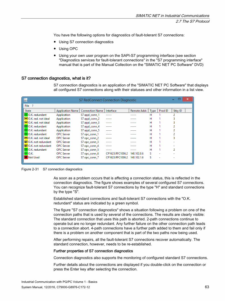
SIMATIC NET in Industrial Communications 2.7 The S7 Protocol
Industrial Communication with PG/PC Volume 1 - Basics System Manual, 12/2016, C79000-G8976-C172-12 63
You have the following options for diagnostics of fault-tolerant S7 connections:
● Using S7 connection diagnostics
● Using OPC
● Using your own user program on the SAPI-S7 programming interface (see section "Diagnostics services for fault-tolerant connections" in the "S7 programming interface" manual that is part of the Manual Collection on the "SIMATIC NET PC Software" DVD)
S7 connection diagnostics, what is it? S7 connection diagnostics is an application of the "SIMATIC NET PC Software" that displays all configured S7 connections along with their statuses and other information in a list view.
Figure 2-31 S7 connection diagnostics
As soon as a problem occurs that is affecting a connection status, this is reflected in the connection diagnostics. The figure shows examples of several configured S7 connections. You can recognize fault-tolerant S7 connections by the type "H" and standard connections by the type "S".
Established standard connections and fault-tolerant S7 connections with the "O.K. redundant" status are indicated by a green symbol.
The figure "S7 connection diagnostics" shows a situation following a problem on one of the connection paths that is used by several of the connections. The results are clearly visible: The standard connection that uses this path is aborted. 2-path connections continue to operate but are no longer redundant. Any further failure on the other connection path leads to a connection abort. 4-path connections have a further path added to them and fail only if there is a problem on another component that is part of the two paths now being used.
After performing repairs, all the fault-tolerant S7 connections recover automatically. The standard connection, however, needs to be re-established.
Further properties of S7 connection diagnostics
Connection diagnostics also supports the monitoring of configured standard S7 connections.
Further details about the connections are displayed if you double-click on the connection or press the Enter key after selecting the connection.
SIMATIC NET in Industrial Communications 2.7 The S7 Protocol
Industrial Communication with PG/PC Volume 1 - Basics 64 System Manual, 12/2016, C79000-G8976-C172-12
Following configuration changes, the display of the connection list is refreshed automatically.
The help system of this application explains further operator input.
How can I diagnose fault-tolerant S7 connections with OPC? You diagnose fault-tolerant S7 connections just like standard S7 connections using the S7-specific diagnostics variables of the SIMATIC NET OPC server. Compared with standard connections, fault-tolerant S7 connections have expanded statuses and the statuses of the connection paths. You can read and monitor these variables with an OPC client application.
Using the supplied tool "OPC Scout V10" as an OPC client, all S7 connections can be diagnosed. This also uses the diagnostics variables of the SIMATIC NET OPC server. You will find further information in the help on the diagnostics view of this application.
2.7.6 S7 protocol - how is it configured?
The S7 protocol is configured as follows Before communication is possible with the S7 protocol, connections must be configured. For this, the "SIMATIC STEP 7 Professional" configuration tool is available. The configured connections are identified by a unique connection name specified during configuration. Two connection types are predefined for the S7 protocol:
● S7 connection: Connection over PROFIBUS or Ethernet
● Fault-tolerant S7 connection: Connection over redundant connection paths
Parameters must be set for every configured connection. When the connection is created, the configuration tool sets default values for these parameters that can be adopted by the user unmodified. The essential parameters are:
● The service access point of the transport layer (TSAP).
● Type of connection:
– S7 connection over PROFIBUS
– S7 connection over Ethernet using the TCP/IP protocol
– S7 connection over Ethernet using the ISO transport protocol
What are unconfigured S7 connections? Normally, connections to partner devices are specified in a configuration. For this, the "SIMATIC STEP 7 Professional" configuration tool is available. There are, however, applications in which data, for example, must be read by a partner device or in which variables must be written or monitored. It is possible to implement this task without configuration so that even third-party software can access communication variables with no considerable effort.
SIMATIC NET in Industrial Communications 2.7 The S7 Protocol
Industrial Communication with PG/PC Volume 1 - Basics System Manual, 12/2016, C79000-G8976-C172-12 65
What are the requirements for using unconfigured S7 connections? To allow access to a device without configuration, all the communication-relevant data of the partner device must be known. Among other things, these include the connection name, the access point (CP selection), the remote TSAP, and the station address.
How can unconfigured S7 connections be created? Unconfigured S7 connections can be created with the OPC server or with the "Communications Settings" configuration tool via "COMLS7".
What are the advantages and disadvantages of unconfigured S7 connections? The advantage of using unconfigured S7 connections is that faster access to partner devices is possible.
The disadvantage of using unconfigured S7 connections is that all communication-relevant information about the partner device must be known. In addition to this, no buffer send/receive services are available for unconfigured connections.
2.7.7 S7 protocol - what are the advantages and disadvantages?
These are the advantages of the S7 protocol Using the S7 protocol has the following advantages:
● All services can be used without restrictions via PROFIBUS and Ethernet.
● Access to partner devices without programming the partners.
● Access control using a password.
● Access (read/write/delete) to the loadable area of an automation system.
● Alarms are buffered and cannot be lost.
● All the advantages of a connection-oriented protocol
These are the disadvantages of the S7 protocol The use of the S7 protocol has the following disadvantages:
● Vendor-dependent, the S7 protocol is implemented only in the SIMATIC S7 spectrum.
● Not compatible with S5 communication.
SIMATIC NET in Industrial Communications 2.8 The SNMP Protocol
Industrial Communication with PG/PC Volume 1 - Basics 66 System Manual, 12/2016, C79000-G8976-C172-12
2.8 The SNMP Protocol
2.8.1 SNMP protocol - what is it?
The SNMP Protocol The SNMP Protocol (Simple Network Management Protocol) is a UDPbased, open protocol for managing networks. It allows central network management for many network components, such as routers, bridges, hubs, printers, servers, and workstations. The primary aims of SNMP are to reduce the complexity of the management functions and the transparent exchange of information or data between different network components. The SNMP protocol supports the monitoring, control, and management of any SNMP-compliant network components.
2.8.2 SNMP protocol - what does a typical system configuration look like? The following section shows how a typical system configuration might appear in Ethernet in which the data communication is implemented between various devices using the SNMP protocol.
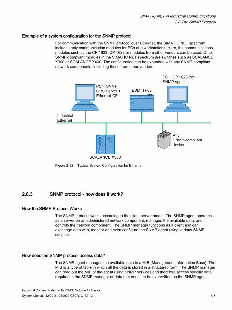
SIMATIC NET in Industrial Communications 2.8 The SNMP Protocol
Industrial Communication with PG/PC Volume 1 - Basics System Manual, 12/2016, C79000-G8976-C172-12 67
Example of a system configuration for the SNMP protocol For communication with the SNMP protocol over Ethernet, the SIMATIC NET spectrum includes only communication modules for PCs and workstations. Here, the communications modules such as the CP 1623, CP 1628 or modules from other vendors can be used. Other SNMP-compliant modules in the SIMATIC NET spectrum are switches such as SCALANCE X300 or SCALANCE X400. The configuration can be expanded with any SNMP-compliant network components, including those from other vendors.
Figure 2-32 Typical System Configuration for Ethernet
2.8.3 SNMP protocol - how does it work?
How the SNMP Protocol Works The SNMP protocol works according to the client-server model. The SNMP agent operates as a server on an administered network component, manages the available data, and controls the network component. The SNMP manager functions as a client and can exchange data with, monitor and even configure the SNMP agent using various SNMP services.
How does the SNMP protocol access data? The SNMP agent manages the available data in a MIB (Management Information Base). The MIB is a type of table in which all the data is stored in a structured form. The SNMP manager can read out the MIB of the agent using SNMP services and therefore access specific data required in the SNMP manager or data that needs to be overwritten on the SNMP agent.
SIMATIC NET in Industrial Communications 2.8 The SNMP Protocol
Industrial Communication with PG/PC Volume 1 - Basics 68 System Manual, 12/2016, C79000-G8976-C172-12
2.8.4 SNMP protocol - which communication services are available?
The SNMP protocol provides the following communication services For communication between an SNMP manager and an SNMP agent, the SNMP protocol basically provides five communication services.
● Get Request: With the "get request" service, the SNMP manager requests data from the SNMP agent that the agent manages in its MIB.
● Get Next Request: The "Get Next Request" service allows access by the SNMP manager to the next data on the SNMP agent.
● Get Response: The "get response" service is the reply to "get request" or "get next request" and is always sent by the SNMP agent to the SNMP manager.
● Set Request: To write data to the SNMP agent, the SNMP manager uses the "set request" service.
● TRAP: Special data can be sent unsolicited and event-driven by the SNMP agent to the SNMP manager. The SNMP agent then uses the "trap" service.
2.8.5 SNMP protocol - how is it configured?
The SNMP protocol is configured as follows Prior to communication with the SNMP protocol, the system configuration of all SNMP-compliant partner devices must be configured. For this, the "SIMATIC STEP 7 Professional" configuration tool is available. The HW Config user program is used to specify several parameters for the SNMP-compliant partner device that uniquely identify the device. The parameters to be configured are:
● Name of the device: Unique, technologically relevant name
● Address of the device: IP address on Ethernet
● Device profile: Describes the structure of the device information available over the SNMP protocol
SIMATIC NET in Industrial Communications 2.8 The SNMP Protocol
Industrial Communication with PG/PC Volume 1 - Basics System Manual, 12/2016, C79000-G8976-C172-12 69
2.8.6 SNMP protocol - what are the advantages and disadvantages?
These are the advantages of the SNMP protocol The SNMP protocol has the following advantages:
● Open protocol supported by many vendors.
● Is widespread in Ethernet networks.
● Many different network components are supported, for example switches, printers, PCs, network adapters.
● Communication can be event-driven reducing network load.
These are the disadvantages of the SNMP protocol The SNMP protocol has the following disadvantages:
● No diagnostics protocol and therefore no network diagnostics possible.
● No statistics available.
● No parameter assignment possible.
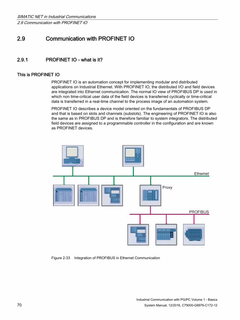
SIMATIC NET in Industrial Communications 2.9 Communication with PROFINET IO
Industrial Communication with PG/PC Volume 1 - Basics 70 System Manual, 12/2016, C79000-G8976-C172-12
2.9 Communication with PROFINET IO
2.9.1 PROFINET IO - what is it?
This is PROFINET IO PROFINET IO is an automation concept for implementing modular and distributed applications on Industrial Ethernet. With PROFINET IO, the distributed I/O and field devices are integrated into Ethernet communication. The normal IO view of PROFIBUS DP is used in which non time-critical user data of the field devices is transferred cyclically or time-critical data is transferred in a real-time channel to the process image of an automation system.
PROFINET IO describes a device model oriented on the fundamentals of PROFIBUS DP and that is based on slots and channels (subslots). The engineering of PROFINET IO is also the same as in PROFIBUS DP and is therefore familiar to system integrators. The distributed field devices are assigned to a programmable controller in the configuration and are known as PROFINET devices.
Figure 2-33 Integration of PROFIBUS in Ethernet Communication
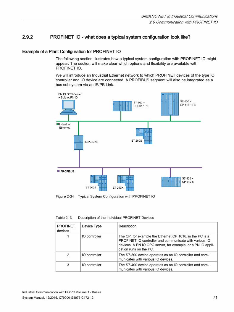
SIMATIC NET in Industrial Communications 2.9 Communication with PROFINET IO
Industrial Communication with PG/PC Volume 1 - Basics System Manual, 12/2016, C79000-G8976-C172-12 71
2.9.2 PROFINET IO - what does a typical system configuration look like?
Example of a Plant Configuration for PROFINET IO The following section illustrates how a typical system configuration with PROFINET IO might appear. The section will make clear which options and flexibility are available with PROFINET IO.
We will introduce an Industrial Ethernet network to which PROFINET devices of the type IO controller and IO device are connected. A PROFIBUS segment will also be integrated as a bus subsystem via an IE/PB Link.
Figure 2-34 Typical System Configuration with PROFINET IO
Table 2- 3 Description of the Individual PROFINET Devices
PROFINET devices
Device Type Description
1 IO controller The CP, for example the Ethernet CP 1616, in the PC is a PROFINET IO controller and communicate with various IO devices. A PN IO OPC server, for example, or a PN IO appli-cation runs on the PC.
2 IO controller The S7-300 device operates as an IO controller and com-municates with various IO devices.
3 IO controller The S7-400 device operates as an IO controller and com-municates with various IO devices.
SIMATIC NET in Industrial Communications 2.9 Communication with PROFINET IO
Industrial Communication with PG/PC Volume 1 - Basics 72 System Manual, 12/2016, C79000-G8976-C172-12
PROFINET devices
Device Type Description
4 IO device In the sense of PROFINET IO, the IE/PB Link has a proxy functionality and represents each underlying PROFIBUS device transparently as a PROFINET IO device on Ethernet.
5 IO device The ET 200S device operates as an IO device and is as-signed to an IO controller.
2.9.3 PROFINET IO - how does it work?
How PROFINET IO Works PROFINET IO integrates the distributed I/O on Industrial Ethernet. Controller and device work according to the provider-consumer model, in which the provider creates and sends data that the consumer receives and processes. The controller-device principle can be compared with the master-slave principle familiar from PROFIBUS DP.
From the perspective of communication, all PROFINET devices have equal rights on Ethernet. Each device is assigned a type during configuration, that specifies how communication is handled according to the provider-consumer model.
The following three device types are distinguished in PROFINET IO:
● The IO controller The IO controller is a programmable controller on which an automation program runs or a CP in a PC on which, for example, an OPC server is implemented.
● The IO device The IO device is a distributed field device assigned to an IO controller.
● The IO supervisor The IO supervisor is a PC/PG with commissioning and diagnostic functions.
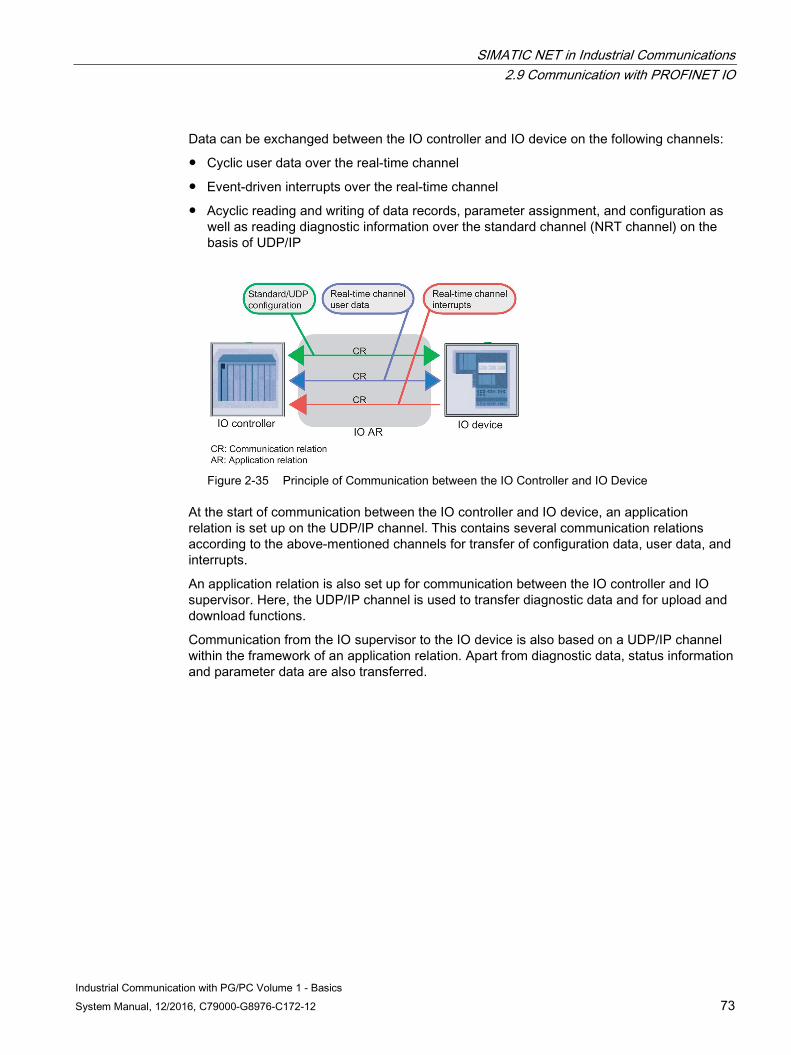
SIMATIC NET in Industrial Communications 2.9 Communication with PROFINET IO
Industrial Communication with PG/PC Volume 1 - Basics System Manual, 12/2016, C79000-G8976-C172-12 73
Data can be exchanged between the IO controller and IO device on the following channels:
● Cyclic user data over the real-time channel
● Event-driven interrupts over the real-time channel
● Acyclic reading and writing of data records, parameter assignment, and configuration as well as reading diagnostic information over the standard channel (NRT channel) on the basis of UDP/IP
Figure 2-35 Principle of Communication between the IO Controller and IO Device
At the start of communication between the IO controller and IO device, an application relation is set up on the UDP/IP channel. This contains several communication relations according to the above-mentioned channels for transfer of configuration data, user data, and interrupts.
An application relation is also set up for communication between the IO controller and IO supervisor. Here, the UDP/IP channel is used to transfer diagnostic data and for upload and download functions.
Communication from the IO supervisor to the IO device is also based on a UDP/IP channel within the framework of an application relation. Apart from diagnostic data, status information and parameter data are also transferred.
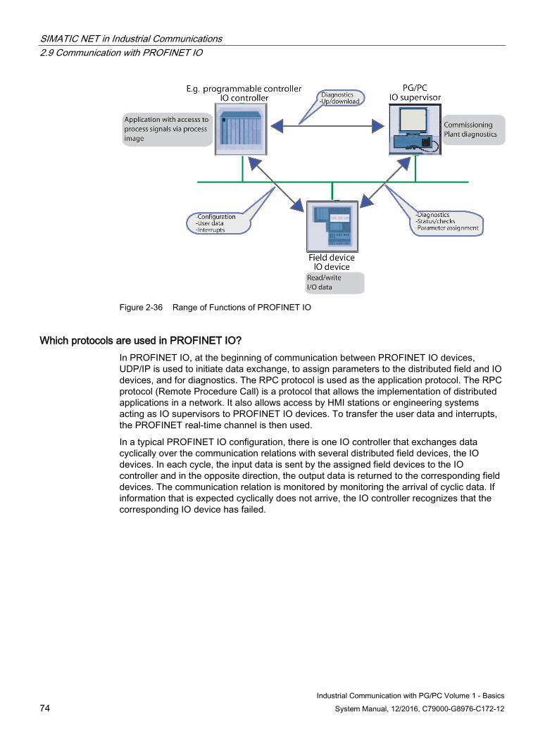
SIMATIC NET in Industrial Communications 2.9 Communication with PROFINET IO
Industrial Communication with PG/PC Volume 1 - Basics 74 System Manual, 12/2016, C79000-G8976-C172-12
Figure 2-36 Range of Functions of PROFINET IO
Which protocols are used in PROFINET IO? In PROFINET IO, at the beginning of communication between PROFINET IO devices, UDP/IP is used to initiate data exchange, to assign parameters to the distributed field and IO devices, and for diagnostics. The RPC protocol is used as the application protocol. The RPC protocol (Remote Procedure Call) is a protocol that allows the implementation of distributed applications in a network. It also allows access by HMI stations or engineering systems acting as IO supervisors to PROFINET IO devices. To transfer the user data and interrupts, the PROFINET real-time channel is then used.
In a typical PROFINET IO configuration, there is one IO controller that exchanges data cyclically over the communication relations with several distributed field devices, the IO devices. In each cycle, the input data is sent by the assigned field devices to the IO controller and in the opposite direction, the output data is returned to the corresponding field devices. The communication relation is monitored by monitoring the arrival of cyclic data. If information that is expected cyclically does not arrive, the IO controller recognizes that the corresponding IO device has failed.
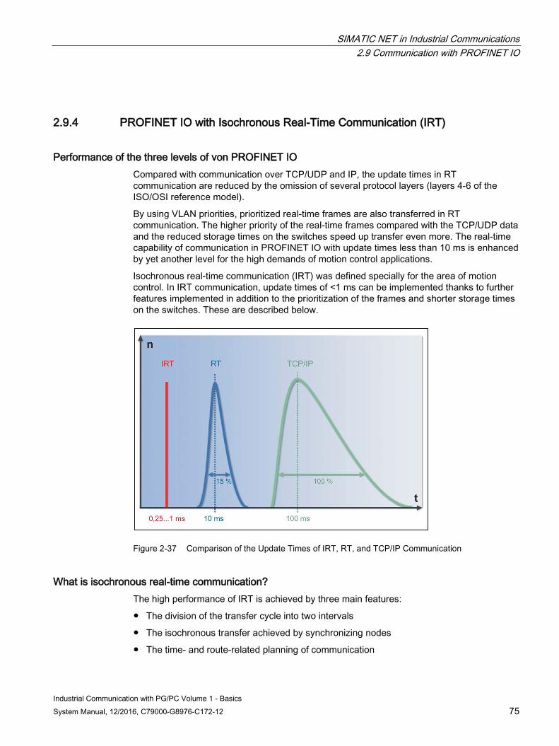
SIMATIC NET in Industrial Communications 2.9 Communication with PROFINET IO
Industrial Communication with PG/PC Volume 1 - Basics System Manual, 12/2016, C79000-G8976-C172-12 75
2.9.4 PROFINET IO with Isochronous Real-Time Communication (IRT)
Performance of the three levels of von PROFINET IO Compared with communication over TCP/UDP and IP, the update times in RT communication are reduced by the omission of several protocol layers (layers 4-6 of the ISO/OSI reference model).
By using VLAN priorities, prioritized real-time frames are also transferred in RT communication. The higher priority of the real-time frames compared with the TCP/UDP data and the reduced storage times on the switches speed up transfer even more. The real-time capability of communication in PROFINET IO with update times less than 10 ms is enhanced by yet another level for the high demands of motion control applications.
Isochronous real-time communication (IRT) was defined specially for the area of motion control. In IRT communication, update times of <1 ms can be implemented thanks to further features implemented in addition to the prioritization of the frames and shorter storage times on the switches. These are described below.
Figure 2-37 Comparison of the Update Times of IRT, RT, and TCP/IP Communication
What is isochronous real-time communication? The high performance of IRT is achieved by three main features:
● The division of the transfer cycle into two intervals
● The isochronous transfer achieved by synchronizing nodes
● The time- and route-related planning of communication
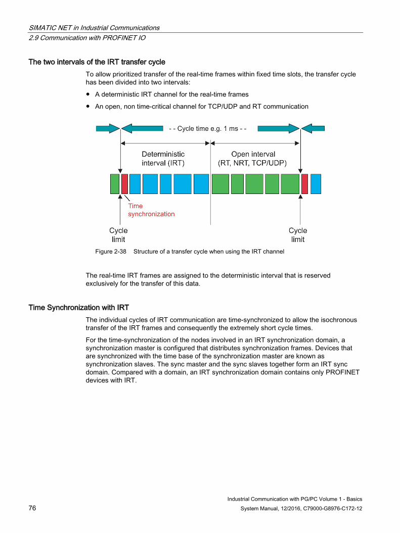
SIMATIC NET in Industrial Communications 2.9 Communication with PROFINET IO
Industrial Communication with PG/PC Volume 1 - Basics 76 System Manual, 12/2016, C79000-G8976-C172-12
The two intervals of the IRT transfer cycle To allow prioritized transfer of the real-time frames within fixed time slots, the transfer cycle has been divided into two intervals:
● A deterministic IRT channel for the real-time frames
● An open, non time-critical channel for TCP/UDP and RT communication
Figure 2-38 Structure of a transfer cycle when using the IRT channel
The real-time IRT frames are assigned to the deterministic interval that is reserved exclusively for the transfer of this data.
Time Synchronization with IRT The individual cycles of IRT communication are time-synchronized to allow the isochronous transfer of the IRT frames and consequently the extremely short cycle times.
For the time-synchronization of the nodes involved in an IRT synchronization domain, a synchronization master is configured that distributes synchronization frames. Devices that are synchronized with the time base of the synchronization master are known as synchronization slaves. The sync master and the sync slaves together form an IRT sync domain. Compared with a domain, an IRT synchronization domain contains only PROFINET devices with IRT.
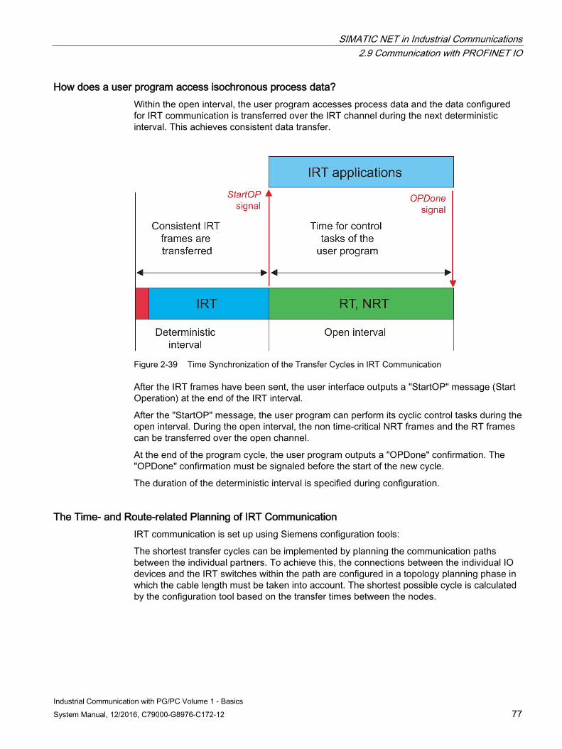
SIMATIC NET in Industrial Communications 2.9 Communication with PROFINET IO
Industrial Communication with PG/PC Volume 1 - Basics System Manual, 12/2016, C79000-G8976-C172-12 77
How does a user program access isochronous process data? Within the open interval, the user program accesses process data and the data configured for IRT communication is transferred over the IRT channel during the next deterministic interval. This achieves consistent data transfer.
Figure 2-39 Time Synchronization of the Transfer Cycles in IRT Communication
After the IRT frames have been sent, the user interface outputs a "StartOP" message (Start Operation) at the end of the IRT interval.
After the "StartOP" message, the user program can perform its cyclic control tasks during the open interval. During the open interval, the non time-critical NRT frames and the RT frames can be transferred over the open channel.
At the end of the program cycle, the user program outputs a "OPDone" confirmation. The "OPDone" confirmation must be signaled before the start of the new cycle.
The duration of the deterministic interval is specified during configuration.
The Time- and Route-related Planning of IRT Communication IRT communication is set up using Siemens configuration tools:
The shortest transfer cycles can be implemented by planning the communication paths between the individual partners. To achieve this, the connections between the individual IO devices and the IRT switches within the path are configured in a topology planning phase in which the cable length must be taken into account. The shortest possible cycle is calculated by the configuration tool based on the transfer times between the nodes.
SIMATIC NET in Industrial Communications 2.9 Communication with PROFINET IO
Industrial Communication with PG/PC Volume 1 - Basics 78 System Manual, 12/2016, C79000-G8976-C172-12
Hardware Requirements for IRT Communication For isochronous data transfer with cycle times less than 1 ms with a jitter of the consecutive cycles of 1 μs, special IRT ASICs are required in the controllers and devices as well as in the switches between them.
Siemens offers various components that allow high-performance IRT communication based on the Ethernet ASICs ERTEC 200 and ERTEC 400:
● The CP 1604 and CP 1616 communications processors with IO-Base software
● The SCALANCE X204IRT and X202IRT switches
● Further components are in development.
Notes on the use of IRT with SOFTNET PNIO
Note
SOFTNET PNIO does not support IRT.
2.9.5 PROFINET IO - which communication services are available?
PROFINET IO provides the following communication services PROFINET IO provides several communication services for communication between a PROFINET IO controller and a PROFINET IO device. A distinction is made between initialization services and productive services. The initialization services are:
● IO Controller Status: With the "IO Controller Status" service, the IO controller can query and change its own status. The statuses CLEAR, OPERATE, and OFFLINE are defined for IO devices.
● Activate IO device: The "Activate IO device" service allows the IO controller to set the IO device to the active state.
● Deactivate IO device: The "Deactivate IO device" service allows the IO controller to set the IO device to the inactive state.
SIMATIC NET in Industrial Communications 2.9 Communication with PROFINET IO
Industrial Communication with PG/PC Volume 1 - Basics System Manual, 12/2016, C79000-G8976-C172-12 79
The productive services are:
● Read IO data: With the "Read IO data" service, the IO controller reads the cyclic input data of the IO device. At the same time, remote status information (provider status) is read from the IO device and the local status information (consumer status) is transferred to the IO device.
● Write IO data: With the "Write IO data" service, the IO controller modifies the output data sent to the IO device cyclically. At the same time, local status information (provider status) is transferred to the IO device.
● Receive and acknowledge interrupts: With the "Receive and acknowledge interrupts" service, the IO controller receives interrupt information from the IO device and can acknowledge this to the IO device.
● Read/write data record: With this service, the IO controller can communicate acyclically with the IO device. The IO controller reads data records from the IO device or writes data records to the IO device.
2.9.6 PROFINET IO - how is it configured?
PROFINET IO is configured as follows To allow communication with PROFINET IO, each PROFINET IO device must be configured. For this, the "SIMATIC STEP 7 Professional" configuration tool is available.
Parameters must be set for every PROFINET IO device. When the device is created, the configuration tool sets default values for these parameters that can be adopted by the user unmodified. The essential parameters are:
● The update time
● Addresses with which the devices can be accessed
Points to Note when Configuring IRT Communication When configuring time-based IRT communication, not only the nodes communicating over the IRT channel but also the addresses of the switches between them must be configured. The controller automatically transfers the planning data to the switches when they start up to allow the transfer lists to be created.
The PROFINET devices with IRT within an IRT synchronization domain can belong to a single or several IO systems. What is important, however, is that all PROFINET devices with IRT configured within an IO system belong to only one IRT synchronization domain. IRT synchronization domains must not overlap. Connections to PROFINET devices of a different IRT synchronization domain are only permitted over PROFINET devices or ports without IRT support.
An IRT synchronization domain may only contain switches with IRT support, no standard switches.
The assignment of individual data packets to the open NRT channel or to the RT or IRT channel is also made using the configuration tools mentioned above.
SIMATIC NET in Industrial Communications 2.9 Communication with PROFINET IO
Industrial Communication with PG/PC Volume 1 - Basics 80 System Manual, 12/2016, C79000-G8976-C172-12
2.9.7 PROFINET IO - what are the advantages?
The advantages of PROFINET IO are as follows Using PROFINET IO has the following advantages:
● Investment protection
● Straightforward system expansion
● Minimizes costs of installation, engineering, and commissioning
● Vertical integration of the levels of the automation pyramid through the integration of PROFIBUS
● The configuration limits of PROFIBUS are expanded while at the same time achieving higher performance
● Coexistent use of real-time and TCP-based communication on one cable
● Scalable real-time communication from powerful to high-performance and isochronous
● Standardized communication between PROFINET devices

SIMATIC NET in Industrial Communications 2.10 Security in SIMATIC NET
Industrial Communication with PG/PC Volume 1 - Basics System Manual, 12/2016, C79000-G8976-C172-12 81
2.10 Security in SIMATIC NET You will find all the information about security in SIMATIC NET in the manual "Industrial Ethernet Security - Setting up security". You will find this document on the Manual Collection of the "SIMATIC NET PC Software" in the "doc" folder or on the support pages using the following entry ID:
60166939 (http://support.automation.siemens.com/WW/view/en/60166939)

SIMATIC NET in Industrial Communications 2.10 Security in SIMATIC NET
Industrial Communication with PG/PC Volume 1 - Basics 82 System Manual, 12/2016, C79000-G8976-C172-12
Industrial Communication with PG/PC Volume 1 - Basics System Manual, 12/2016, C79000-G8976-C172-12 83
Basics of the OPC Interface 3
Overview The following section provides you with an overview of the basics of OPC and the applications of OPC with SIMATIC NET.
It answers questions about the basics of OPC and helps you become familiar with the terminology of OPC and provides you with explanations of the individual terms. It briefly outlines your advantages when using OPC with SIMATIC NET, namely the OPC Scout, symbols and data OCX. It provides you with an insight into the specifications of access to process data (OPC Data Access), the transfer of hardware interrupts and events (Alarms & Events), access to the Internet (OPC XML).
The properties of the specification OPC Unified Architecture (OPC UA) are also described. And last but not least, you obtain information on the performance of OPC.
After reading this section, with the detailed information on using OPC in volume 2 of this manual, you should not have any difficulties.
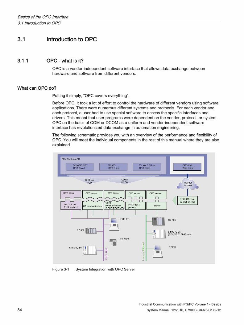
Basics of the OPC Interface 3.1 Introduction to OPC
Industrial Communication with PG/PC Volume 1 - Basics 84 System Manual, 12/2016, C79000-G8976-C172-12
3.1 Introduction to OPC
3.1.1 OPC - what is it? OPC is a vendor-independent software interface that allows data exchange between hardware and software from different vendors.
What can OPC do? Putting it simply, "OPC covers everything".
Before OPC, it took a lot of effort to control the hardware of different vendors using software applications. There were numerous different systems and protocols. For each vendor and each protocol, a user had to use special software to access the specific interfaces and drivers. This meant that user programs were dependent on the vendor, protocol, or system. OPC on the basis of COM or DCOM as a uniform and vendor-independent software interface has revolutionized data exchange in automation engineering.
The following schematic provides you with an overview of the performance and flexibility of OPC. You will meet the individual components in the rest of this manual where they are also explained.
Figure 3-1 System Integration with OPC Server
Basics of the OPC Interface 3.1 Introduction to OPC
Industrial Communication with PG/PC Volume 1 - Basics System Manual, 12/2016, C79000-G8976-C172-12 85
3.1.2 Advantages of OPC Particular advantages of OPC:
● The symbols
● The OPC Scout
● The SIMATIC NET OPC Data Control
What are the advantages of using symbols? Simple symbolic access to process variables of SIEMENS S7 controllers.
Symbols are used during STEP 7 configuration. The time and effort invested there pays dividends here. OPC uses the same symbols and STEP 7.
You can continue to use the symbol definitions specified in the STEP 7 configuration in OPC.
The use of symbols allows flexible programming of OPC clients.
You save time, money, work, and above all avoid potential sources of error.
How does the OPC Scout reduce the workload? The OPC Scout of SIMATIC NET provides you with a powerful tool for simple access to process variables.
With the OPC Scout, you can test an OPC application or commission the OPC server.
The OPC Scout shows you the namespace of the variables consisting of communication connections and symbolic names.
Via the OPC server, the OPC Scout provides you with access to all process variables you can reach using the configured protocols and connections.
With the OPC Scout, you can monitor the values of process variables, and read, write, or generate values.
The OPC Scout also shows you the status of the communication connections. To do this, it makes use of the properties of the process variables or uses information variables. This allows you to recognize when a partner device is not available.
How does SIMATIC NET OPC Data Control make it easier to access data? With Data Control, you can create simple OPC clients quickly anywhere where you can access ActiveX controls, for example in Visual Basic. Convenient and simple access to process data is possible.
This Data control accesses process data obtained by the OPC server.
The display controls are elements for visualizing process data. They receive their data via the SIMATIC NET OPC Data control and not directly by access to OPC or another interface.
To be able to display or enter process data, you must connect the property of an ActiveX control with a property of an OPC variable via the SIMATIC NET OPC data control.
The properties of an OPC item are value, quality, and timestamp. It is, for example, easy to interconnect a background color with the quality of an OPC variable. For example, the color
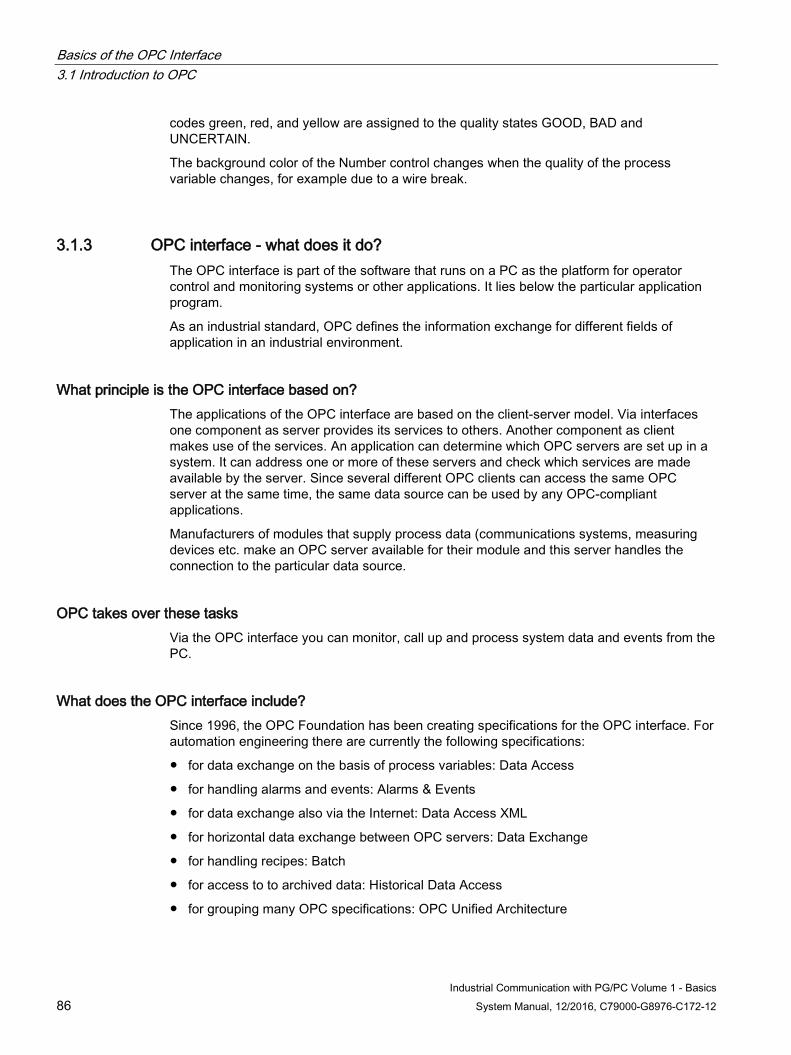
Basics of the OPC Interface 3.1 Introduction to OPC
Industrial Communication with PG/PC Volume 1 - Basics 86 System Manual, 12/2016, C79000-G8976-C172-12
codes green, red, and yellow are assigned to the quality states GOOD, BAD and UNCERTAIN.
The background color of the Number control changes when the quality of the process variable changes, for example due to a wire break.
3.1.3 OPC interface - what does it do? The OPC interface is part of the software that runs on a PC as the platform for operator control and monitoring systems or other applications. It lies below the particular application program.
As an industrial standard, OPC defines the information exchange for different fields of application in an industrial environment.
What principle is the OPC interface based on? The applications of the OPC interface are based on the client-server model. Via interfaces one component as server provides its services to others. Another component as client makes use of the services. An application can determine which OPC servers are set up in a system. It can address one or more of these servers and check which services are made available by the server. Since several different OPC clients can access the same OPC server at the same time, the same data source can be used by any OPC-compliant applications.
Manufacturers of modules that supply process data (communications systems, measuring devices etc. make an OPC server available for their module and this server handles the connection to the particular data source.
OPC takes over these tasks Via the OPC interface you can monitor, call up and process system data and events from the PC.
What does the OPC interface include? Since 1996, the OPC Foundation has been creating specifications for the OPC interface. For automation engineering there are currently the following specifications:
● for data exchange on the basis of process variables: Data Access
● for handling alarms and events: Alarms & Events
● for data exchange also via the Internet: Data Access XML
● for horizontal data exchange between OPC servers: Data Exchange
● for handling recipes: Batch
● for access to to archived data: Historical Data Access
● for grouping many OPC specifications: OPC Unified Architecture
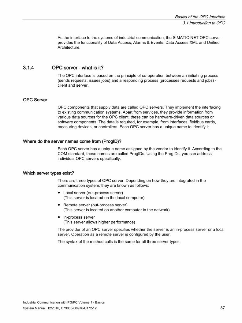
Basics of the OPC Interface 3.1 Introduction to OPC
Industrial Communication with PG/PC Volume 1 - Basics System Manual, 12/2016, C79000-G8976-C172-12 87
As the interface to the systems of industrial communication, the SIMATIC NET OPC server provides the functionality of Data Access, Alarms & Events, Data Access XML and Unified Architecture.
3.1.4 OPC server - what is it? The OPC interface is based on the principle of co-operation between an initiating process (sends requests, issues jobs) and a responding process (processes requests and jobs) - client and server.
OPC Server OPC components that supply data are called OPC servers. They implement the interfacing to existing communication systems. Apart from services, they provide information from various data sources for the OPC client; these can be hardware-driven data sources or software components. The data is required, for example, from interfaces, fieldbus cards, measuring devices, or controllers. Each OPC server has a unique name to identify it.
Where do the server names come from (ProgID)? Each OPC server has a unique name assigned by the vendor to identify it. According to the COM standard, these names are called ProgIDs. Using the ProgIDs, you can address individual OPC servers specifically.
Which server types exist? There are three types of OPC server. Depending on how they are integrated in the communication system, they are known as follows:
● Local server (out-process server) (This server is located on the local computer)
● Remote server (out-process server) (This server is located on another computer in the network)
● In-process server (This server allows higher performance)
The provider of an OPC server specifies whether the server is an in-process server or a local server. Operation as a remote server is configured by the user.
The syntax of the method calls is the same for all three server types.
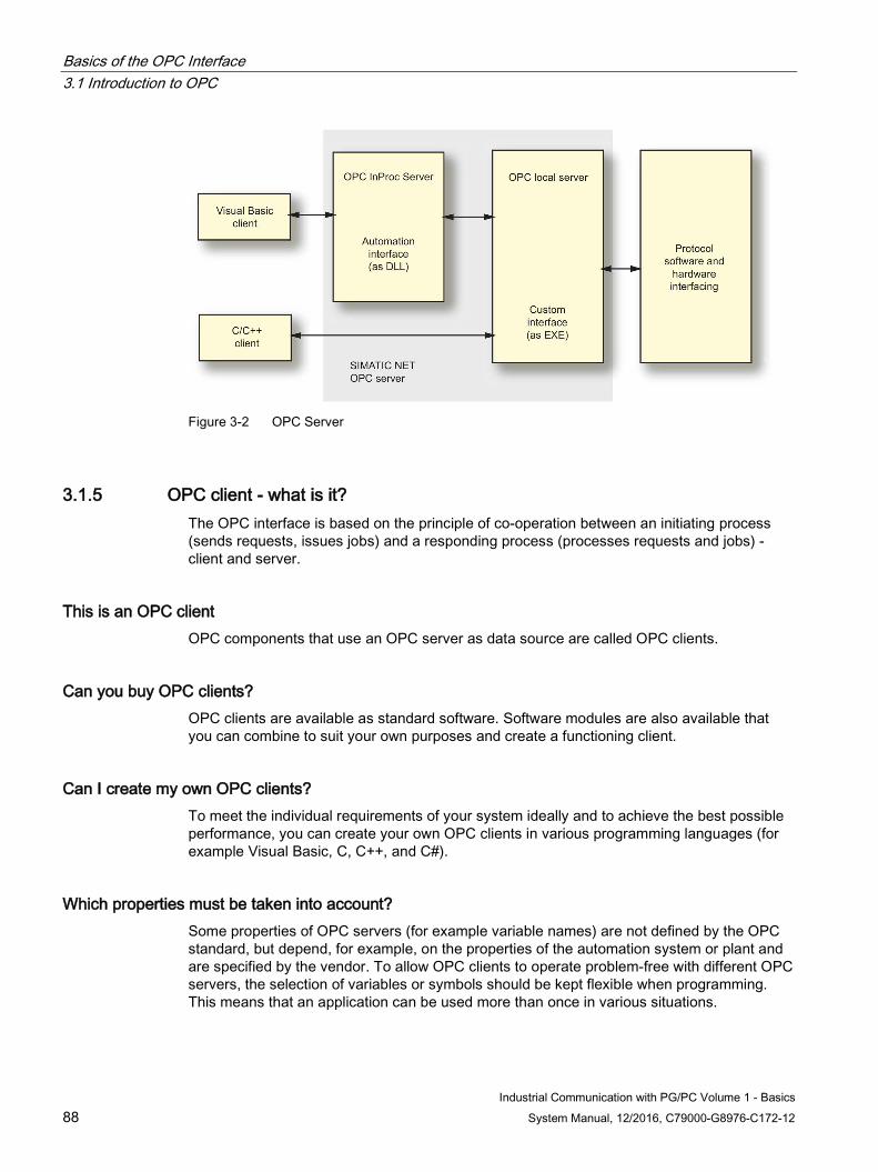
Basics of the OPC Interface 3.1 Introduction to OPC
Industrial Communication with PG/PC Volume 1 - Basics 88 System Manual, 12/2016, C79000-G8976-C172-12
Figure 3-2 OPC Server
3.1.5 OPC client - what is it? The OPC interface is based on the principle of co-operation between an initiating process (sends requests, issues jobs) and a responding process (processes requests and jobs) - client and server.
This is an OPC client OPC components that use an OPC server as data source are called OPC clients.
Can you buy OPC clients? OPC clients are available as standard software. Software modules are also available that you can combine to suit your own purposes and create a functioning client.
Can I create my own OPC clients? To meet the individual requirements of your system ideally and to achieve the best possible performance, you can create your own OPC clients in various programming languages (for example Visual Basic, C, C++, and C#).
Which properties must be taken into account? Some properties of OPC servers (for example variable names) are not defined by the OPC standard, but depend, for example, on the properties of the automation system or plant and are specified by the vendor. To allow OPC clients to operate problem-free with different OPC servers, the selection of variables or symbols should be kept flexible when programming. This means that an application can be used more than once in various situations.
Basics of the OPC Interface 3.1 Introduction to OPC
Industrial Communication with PG/PC Volume 1 - Basics System Manual, 12/2016, C79000-G8976-C172-12 89
3.1.6 Server and client - how do they work together?
Server and client work together Server and client communicate on the basis of COM or DCOM. The client does not access the server directly but with the aid of the COM library. By specifying the ProgID, the OPC client can address each required OPC server directly.
The client program does not notice a difference between access via COM or DCOM.
Figure 3-3 COM on the local computer
Figure 3-4 COM on the remote computer
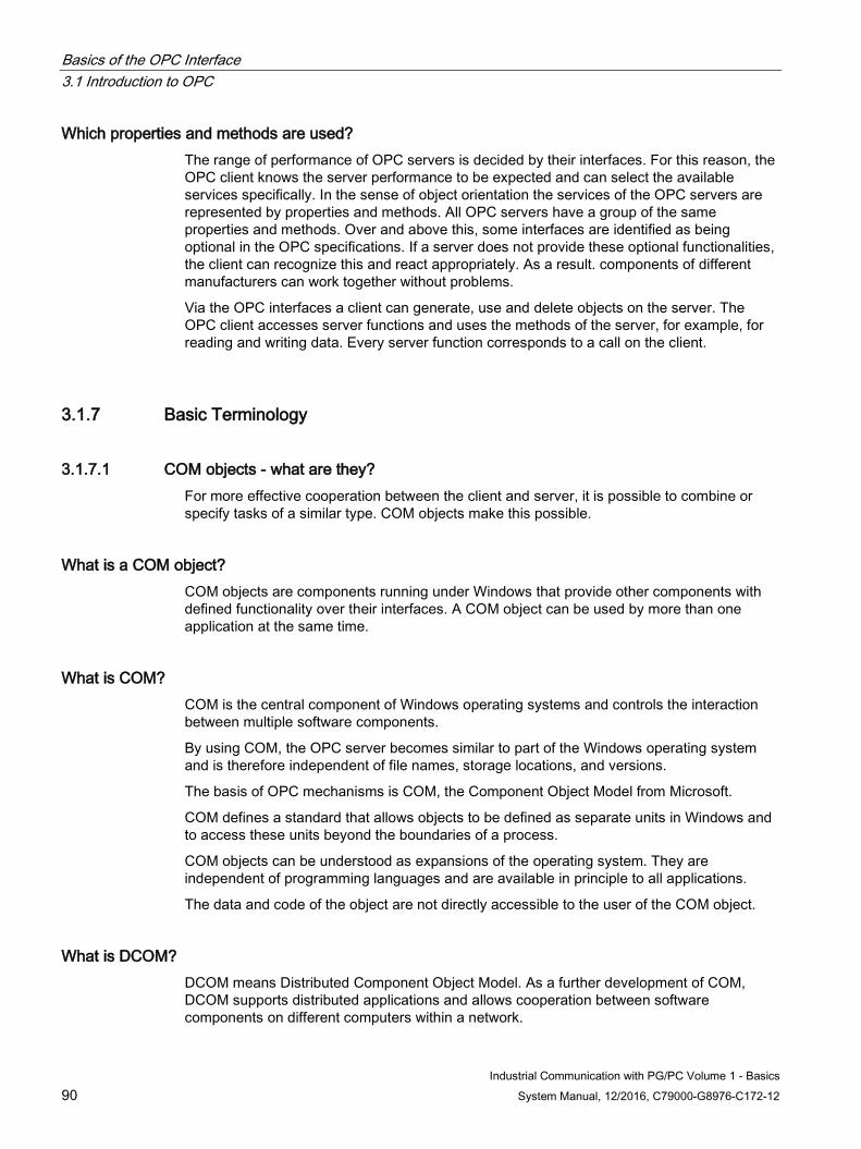
Basics of the OPC Interface 3.1 Introduction to OPC
Industrial Communication with PG/PC Volume 1 - Basics 90 System Manual, 12/2016, C79000-G8976-C172-12
Which properties and methods are used? The range of performance of OPC servers is decided by their interfaces. For this reason, the OPC client knows the server performance to be expected and can select the available services specifically. In the sense of object orientation the services of the OPC servers are represented by properties and methods. All OPC servers have a group of the same properties and methods. Over and above this, some interfaces are identified as being optional in the OPC specifications. If a server does not provide these optional functionalities, the client can recognize this and react appropriately. As a result. components of different manufacturers can work together without problems.
Via the OPC interfaces a client can generate, use and delete objects on the server. The OPC client accesses server functions and uses the methods of the server, for example, for reading and writing data. Every server function corresponds to a call on the client.
3.1.7 Basic Terminology
3.1.7.1 COM objects - what are they? For more effective cooperation between the client and server, it is possible to combine or specify tasks of a similar type. COM objects make this possible.
What is a COM object? COM objects are components running under Windows that provide other components with defined functionality over their interfaces. A COM object can be used by more than one application at the same time.
What is COM? COM is the central component of Windows operating systems and controls the interaction between multiple software components.
By using COM, the OPC server becomes similar to part of the Windows operating system and is therefore independent of file names, storage locations, and versions.
The basis of OPC mechanisms is COM, the Component Object Model from Microsoft.
COM defines a standard that allows objects to be defined as separate units in Windows and to access these units beyond the boundaries of a process.
COM objects can be understood as expansions of the operating system. They are independent of programming languages and are available in principle to all applications.
The data and code of the object are not directly accessible to the user of the COM object.
What is DCOM? DCOM means Distributed Component Object Model. As a further development of COM, DCOM supports distributed applications and allows cooperation between software components on different computers within a network.
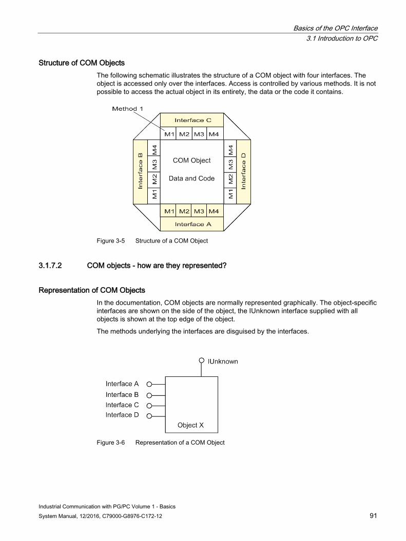
Basics of the OPC Interface 3.1 Introduction to OPC
Industrial Communication with PG/PC Volume 1 - Basics System Manual, 12/2016, C79000-G8976-C172-12 91
Structure of COM Objects The following schematic illustrates the structure of a COM object with four interfaces. The object is accessed only over the interfaces. Access is controlled by various methods. It is not possible to access the actual object in its entirety, the data or the code it contains.
Figure 3-5 Structure of a COM Object
3.1.7.2 COM objects - how are they represented?
Representation of COM Objects In the documentation, COM objects are normally represented graphically. The object-specific interfaces are shown on the side of the object, the IUnknown interface supplied with all objects is shown at the top edge of the object.
The methods underlying the interfaces are disguised by the interfaces.
Figure 3-6 Representation of a COM Object
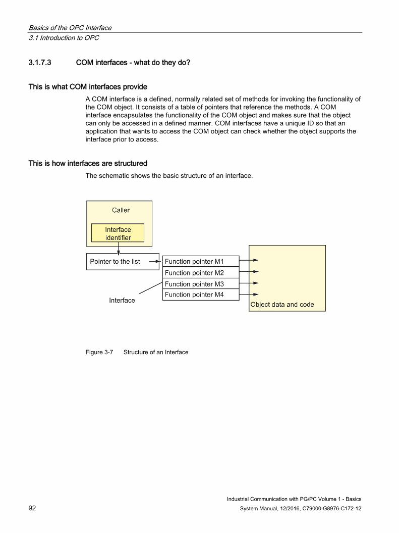
Basics of the OPC Interface 3.1 Introduction to OPC
Industrial Communication with PG/PC Volume 1 - Basics 92 System Manual, 12/2016, C79000-G8976-C172-12
3.1.7.3 COM interfaces - what do they do?
This is what COM interfaces provide A COM interface is a defined, normally related set of methods for invoking the functionality of the COM object. It consists of a table of pointers that reference the methods. A COM interface encapsulates the functionality of the COM object and makes sure that the object can only be accessed in a defined manner. COM interfaces have a unique ID so that an application that wants to access the COM object can check whether the object supports the interface prior to access.
This is how interfaces are structured The schematic shows the basic structure of an interface.
Figure 3-7 Structure of an Interface
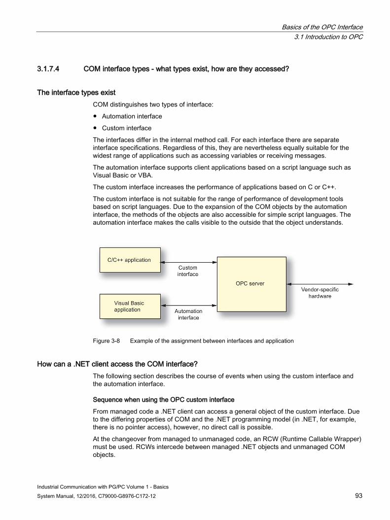
Basics of the OPC Interface 3.1 Introduction to OPC
Industrial Communication with PG/PC Volume 1 - Basics System Manual, 12/2016, C79000-G8976-C172-12 93
3.1.7.4 COM interface types - what types exist, how are they accessed?
The interface types exist COM distinguishes two types of interface:
● Automation interface
● Custom interface
The interfaces differ in the internal method call. For each interface there are separate interface specifications. Regardless of this, they are nevertheless equally suitable for the widest range of applications such as accessing variables or receiving messages.
The automation interface supports client applications based on a script language such as Visual Basic or VBA.
The custom interface increases the performance of applications based on C or C++.
The custom interface is not suitable for the range of performance of development tools based on script languages. Due to the expansion of the COM objects by the automation interface, the methods of the objects are also accessible for simple script languages. The automation interface makes the calls visible to the outside that the object understands.
Figure 3-8 Example of the assignment between interfaces and application
How can a .NET client access the COM interface? The following section describes the course of events when using the custom interface and the automation interface.
Sequence when using the OPC custom interface
From managed code a .NET client can access a general object of the custom interface. Due to the differing properties of COM and the .NET programming model (in .NET, for example, there is no pointer access), however, no direct call is possible.
At the changeover from managed to unmanaged code, an RCW (Runtime Callable Wrapper) must be used. RCWs intercede between managed .NET objects and unmanaged COM objects.
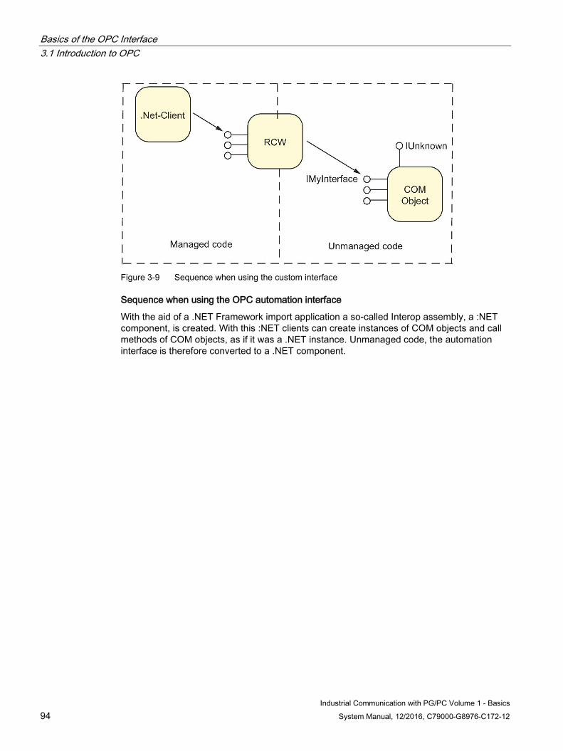
Basics of the OPC Interface 3.1 Introduction to OPC
Industrial Communication with PG/PC Volume 1 - Basics 94 System Manual, 12/2016, C79000-G8976-C172-12
Figure 3-9 Sequence when using the custom interface
Sequence when using the OPC automation interface
With the aid of a .NET Framework import application a so-called Interop assembly, a :NET component, is created. With this :NET clients can create instances of COM objects and call methods of COM objects, as if it was a .NET instance. Unmanaged code, the automation interface is therefore converted to a .NET component.
Basics of the OPC Interface 3.2 Data Access
Industrial Communication with PG/PC Volume 1 - Basics System Manual, 12/2016, C79000-G8976-C172-12 95
3.2 Data Access
3.2.1 Introduction to the Data Access Interface
3.2.1.1 What can OPC Data Access do? The data access interface is a worldwide vendor-independent standard for reading, writing and monitoring process data. The communication is based on the Microsoft COM protocol. This standard has been accepted by both users and manufacturers. The user programs are simple Office applications right through to sophisticated HMI (Human Machine Interface) or SCADA (Supervisory Control and Data Acquisition) systems.
OPC Data Access can do this The OPC Data Access specification defines the interface between client and server programs for process data communication. Data access servers allow one or more data access clients transparent access to the widest variety of data sources (e.g. temperature sensors) and data sinks (e.g. controllers). These data sources and sinks can be located on I/O cards plugged directly into the PC, but they can also be located on any device such as controllers, input/output modules or similar that are connected via serial connections or via fieldbuses. Of course a data access client can also access several data access servers at the same time.
What are data access clients? Data access clients can be very simple Excel sheets or extensive programs (e.g. Visual Basic). Data access clients can, however, also be components of larger programs.
What is a data access server? Data access servers can be simple programs that, for example, make access to the registers of a PLC via a serial interface possible. More complex programs are also possible, that make access to numerous variables on a large number of devices possible via extensive communications mechanisms. Data access servers can also be part of larger programs and make data available to these programs.
3.2.1.2 OPC data access - what is it?
With OPC data access you can access process variables Data access is an OPC specification for accessing process data using variables. An OPC server for data access manages the process variables and the various options for accessing these variables. This allows it to:
● Read the value of one or more process variables
● Modify the value of one or more process variables by writing a new value
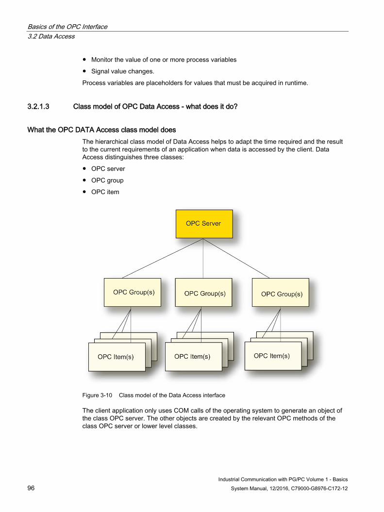
Basics of the OPC Interface 3.2 Data Access
Industrial Communication with PG/PC Volume 1 - Basics 96 System Manual, 12/2016, C79000-G8976-C172-12
● Monitor the value of one or more process variables
● Signal value changes.
Process variables are placeholders for values that must be acquired in runtime.
3.2.1.3 Class model of OPC Data Access - what does it do?
What the OPC DATA Access class model does The hierarchical class model of Data Access helps to adapt the time required and the result to the current requirements of an application when data is accessed by the client. Data Access distinguishes three classes:
● OPC server
● OPC group
● OPC item
Figure 3-10 Class model of the Data Access interface
The client application only uses COM calls of the operating system to generate an object of the class OPC server. The other objects are created by the relevant OPC methods of the class OPC server or lower level classes.
Basics of the OPC Interface 3.2 Data Access
Industrial Communication with PG/PC Volume 1 - Basics System Manual, 12/2016, C79000-G8976-C172-12 97
What does the class model apply to? The class model applies both to the automation interface and to the custom interface.
3.2.1.4 OPC server class - what does it do?
This is what the OPC server class does At the top, there is the OPC server class. Every OPC server belongs to this class. This class provides access for all other services of the data access server.
With the aid of class-specific attributes and methods, you can obtain information on the status, version, and (optionally) name space of the available process variables. An object of the OPC server class manages the instances of the underlying OPC group class.
3.2.1.5 OPC group class - what does it do?
This is what the OPC group class does The OPC group class is the class immediately below the OPC server and is used to structure the process variables used by the OPC server. An OPC client can use several objects of this class at the same time. A client can use the objects of the OPC Group to generate suitable units of process variables and run operations with them. For example, all process variables on a given screen page of an operator control and monitoring system can be combined in the same group.
The OPC group class defines methods that can be used to read and write the values of the process variables.
With some methods (reading and writing OPC items), several variables can be put together in one job and transferred at the same time. In many cases, the OPC server can also run an additional internal optimization. In particular when using an OPC server via the network, these group operations allow a high execution speed. A series of individual jobs at short intervals will normally result in poorer performance.
As of Data Access specification 3.00, cyclic keepalive monitoring of the OPC server can be set (KeepAliveTime) using the OPC group class. Even if process variables do not change, a checkback function (without data values) is called on the OPC client by the OPC server.
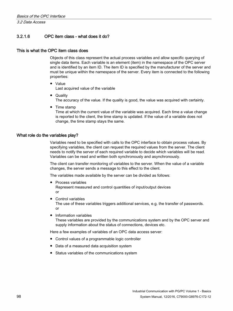
Basics of the OPC Interface 3.2 Data Access
Industrial Communication with PG/PC Volume 1 - Basics 98 System Manual, 12/2016, C79000-G8976-C172-12
3.2.1.6 OPC item class - what does it do?
This is what the OPC item class does Objects of this class represent the actual process variables and allow specific querying of single data items. Each variable is an element (item) in the namespace of the OPC server and is identified by an item ID. The item ID is specified by the manufacturer of the server and must be unique within the namespace of the server. Every item is connected to the following properties:
● Value Last acquired value of the variable
● Quality The accuracy of the value. If the quality is good, the value was acquired with certainty.
● Time stamp Time at which the current value of the variable was acquired. Each time a value change is reported to the client, the time stamp is updated. If the value of a variable does not change, the time stamp stays the same.
What role do the variables play? Variables need to be specified with calls to the OPC interface to obtain process values. By specifying variables, the client can request the required values from the server. The client needs to notify the server of each required variable to decide which variables will be read. Variables can be read and written both synchronously and asynchronously.
The client can transfer monitoring of variables to the server. When the value of a variable changes, the server sends a message to this effect to the client.
The variables made available by the server can be divided as follows:
● Process variables Represent measured and control quantities of input/output devices or
● Control variables The use of these variables triggers additional services, e.g. the transfer of passwords. or
● Information variables These variables are provided by the communications system and by the OPC server and supply information about the status of connections, devices etc.
Here a few examples of variables of an OPC data access server:
● Control values of a programmable logic controller
● Data of a measured data acquisition system
● Status variables of the communications system

Basics of the OPC Interface 3.2 Data Access
Industrial Communication with PG/PC Volume 1 - Basics System Manual, 12/2016, C79000-G8976-C172-12 99
3.2.1.7 OPC Data Access - what are the interface specifications?
There are two interface specifications for OPC Data Access The Automation and Custom interfaces are specified for Data Access:
● Data Access Automation Interface, Standard, February 4, 1999, Version 2.02 (and subsequent versions)
● Data Access Custom Interface, Standard, March 4, 2003, Version 3.00
You will find an overview of the specifications in the references in volume 2.
Basics of the OPC Interface 3.3 OPC Alarms & Events
Industrial Communication with PG/PC Volume 1 - Basics 100 System Manual, 12/2016, C79000-G8976-C172-12
3.3 OPC Alarms & Events
3.3.1 Introduction to OPC Alarms & Events
3.3.1.1 OPC Alarms & Events - what does it mean?
This is Alarms & Events Alarms & Events is a specification for transferring process alarms and events. It is designed to be flexible and can therefore be used on the widest range of event sources. The range extends from simple events right through to complex events and even events requiring acknowledgment.
The OPC specification defines the possible status changes for conditional events in a status diagram.
What is Alarms & Events used for? Alarms-&-events servers are used for example to
● Recognize events - e.g. tank filling reached,
● Determine the status of an event - tank full
● Confirm an event - reaching tank filling recognized,
● Monitor the confirmation - the confirmation is monitored by the tank alarm signaler, the alarm was detected, the warning signal can be turned off.
New events can also be signaled without confirmation.
The standardized OPC Alarms & Events interface allows the handling of these requirements.
3.3.1.2 Events and event messages - what are they?
These are events Events are special states in the process that must be signaled to a recipient. Which events are signaled to the OPC client is set by the OPC client using filter criteria.
All events that match the selected filter criteria must be transferred from the producer of the event to the user. This distinguishes Alarms & Events from Data Access. During monitoring of variables, only the value changes within the specified timebase are signaled.
Basics of the OPC Interface 3.3 OPC Alarms & Events
Industrial Communication with PG/PC Volume 1 - Basics System Manual, 12/2016, C79000-G8976-C172-12 101
These are event messages The message contains the parameters defined in the OPC specification and possibly also associated values specified by the vendor.
There are simple event messages and more complex state-related messages. For these complex state-related messages, the sender of an event can demand an acknowledgment by the OPC client.
Event Types The OPC specification defines three types of event:
● Condition-related events These signal the status changes defined in the OPC status model and are related to defined conditions.
● Tracking events These signal changes in the process if, for example, a user changes the setpoint of a controller.
● Simple events These signal all other events that do not involve a status, for example, the failure of a system component.
The OPC specification defines the syntax of the interface for receiving messages. What types of event the server supplies is specified by the vendor of the OPC server.
3.3.1.3 Class model of OPC Alarms & Events - what does it do?
The class model of OPC Alarms & Events does the following: The class model of Alarms & Events allows the adaptation of the OPC client to the requirements of an automation solution. Alarms & Events distinguishes three classes:
● OPC event server
● OPC event subscription
● OPC event area browser
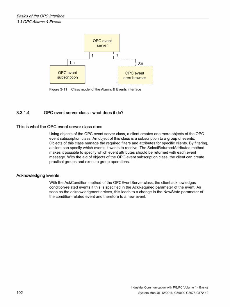
Basics of the OPC Interface 3.3 OPC Alarms & Events
Industrial Communication with PG/PC Volume 1 - Basics 102 System Manual, 12/2016, C79000-G8976-C172-12
Figure 3-11 Class model of the Alarms & Events interface
3.3.1.4 OPC event server class - what does it do?
This is what the OPC event server class does Using objects of the OPC event server class, a client creates one more objects of the OPC event subscription class. An object of this class is a subscription to a group of events. Objects of this class manage the required filters and attributes for specific clients. By filtering, a client can specify which events it wants to receive. The SelectReturnedAttributes method makes it possible to specify which event attributes should be returned with each event message. With the aid of objects of the OPC event subscription class, the client can create practical groups and execute group operations.
Acknowledging Events With the AckCondition method of the OPCEventServer class, the client acknowledges condition-related events if this is specified in the AckRequired parameter of the event. As soon as the acknowledgment arrives, this leads to a change in the NewState parameter of the condition-related event and therefore to a new event.
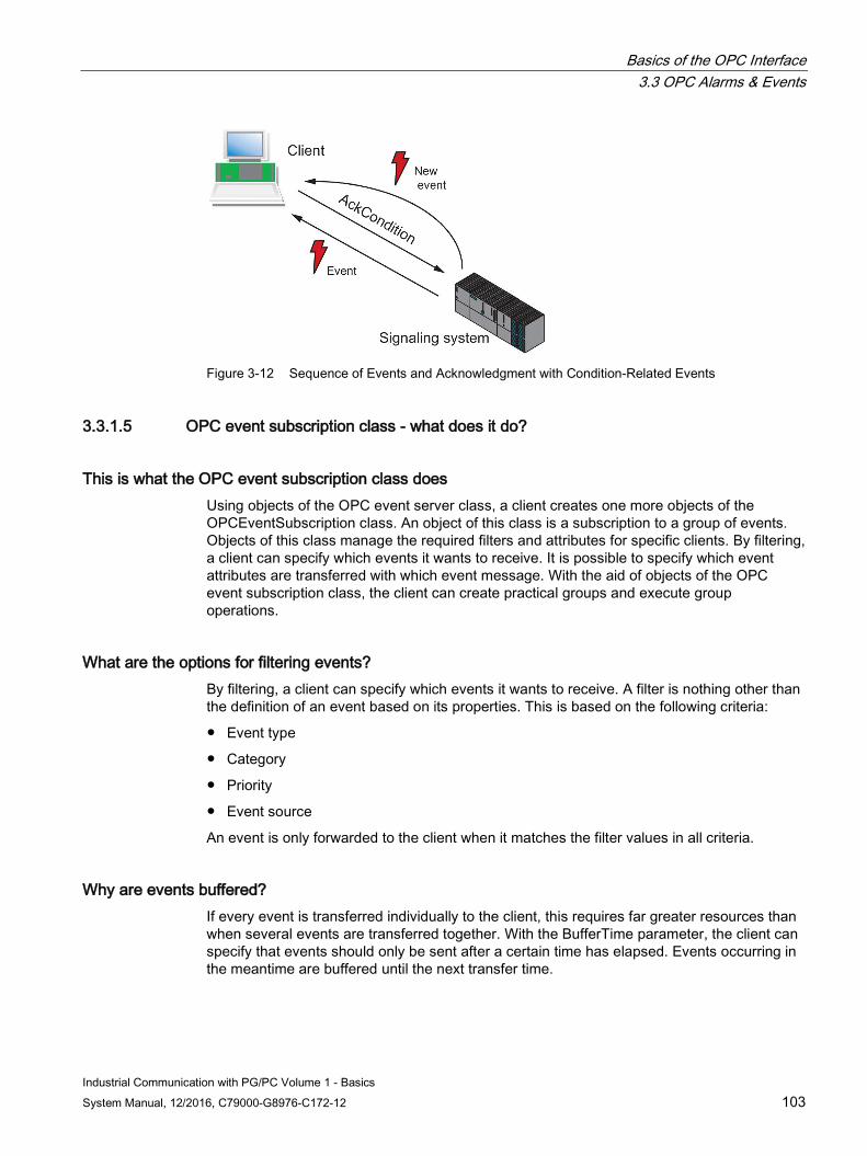
Basics of the OPC Interface 3.3 OPC Alarms & Events
Industrial Communication with PG/PC Volume 1 - Basics System Manual, 12/2016, C79000-G8976-C172-12 103
Figure 3-12 Sequence of Events and Acknowledgment with Condition-Related Events
3.3.1.5 OPC event subscription class - what does it do?
This is what the OPC event subscription class does Using objects of the OPC event server class, a client creates one more objects of the OPCEventSubscription class. An object of this class is a subscription to a group of events. Objects of this class manage the required filters and attributes for specific clients. By filtering, a client can specify which events it wants to receive. It is possible to specify which event attributes are transferred with which event message. With the aid of objects of the OPC event subscription class, the client can create practical groups and execute group operations.
What are the options for filtering events? By filtering, a client can specify which events it wants to receive. A filter is nothing other than the definition of an event based on its properties. This is based on the following criteria:
● Event type
● Category
● Priority
● Event source
An event is only forwarded to the client when it matches the filter values in all criteria.
Why are events buffered? If every event is transferred individually to the client, this requires far greater resources than when several events are transferred together. With the BufferTime parameter, the client can specify that events should only be sent after a certain time has elapsed. Events occurring in the meantime are buffered until the next transfer time.
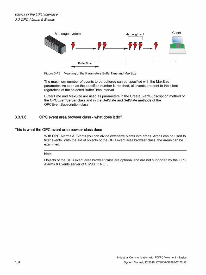
Basics of the OPC Interface 3.3 OPC Alarms & Events
Industrial Communication with PG/PC Volume 1 - Basics 104 System Manual, 12/2016, C79000-G8976-C172-12
Figure 3-13 Meaning of the Parameters BufferTime and MaxSize
The maximum number of events to be buffered can be specified with the MaxSize parameter. As soon as the specified number is reached, all events are sent to the client regardless of the selected BufferTime interval.
BufferTime and MaxSize are used as parameters in the CreateEventSubscription method of the OPCEventServer class and in the GetState and SetState methods of the OPCEventSubscription class.
3.3.1.6 OPC event area browser class - what does it do?
This is what the OPC event area bowser class does With OPC Alarms & Events you can divide extensive plants into areas. Areas can be used to filter events. With the aid of objects of the OPC event area browser class, the areas can be examined.
Note
Objects of the OPC event area browser class are optional and are not supported by the OPC Alarms & Events server of SIMATIC NET.
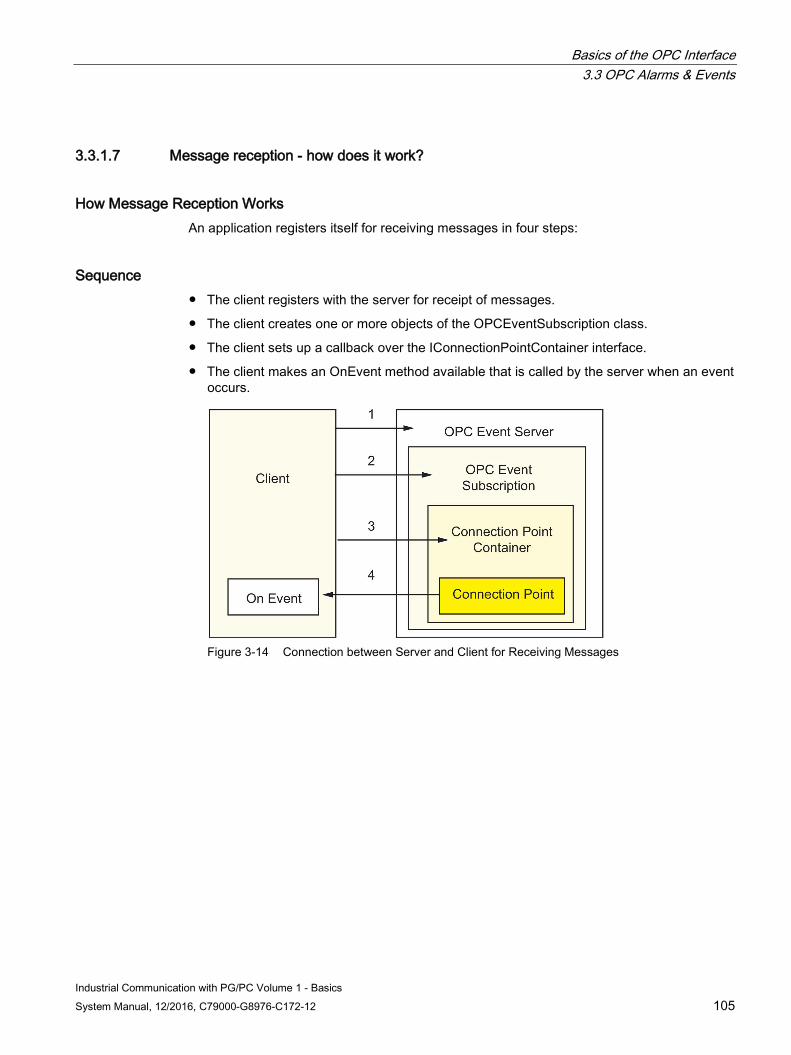
Basics of the OPC Interface 3.3 OPC Alarms & Events
Industrial Communication with PG/PC Volume 1 - Basics System Manual, 12/2016, C79000-G8976-C172-12 105
3.3.1.7 Message reception - how does it work?
How Message Reception Works An application registers itself for receiving messages in four steps:
Sequence ● The client registers with the server for receipt of messages.
● The client creates one or more objects of the OPCEventSubscription class.
● The client sets up a callback over the IConnectionPointContainer interface.
● The client makes an OnEvent method available that is called by the server when an event occurs.
Figure 3-14 Connection between Server and Client for Receiving Messages
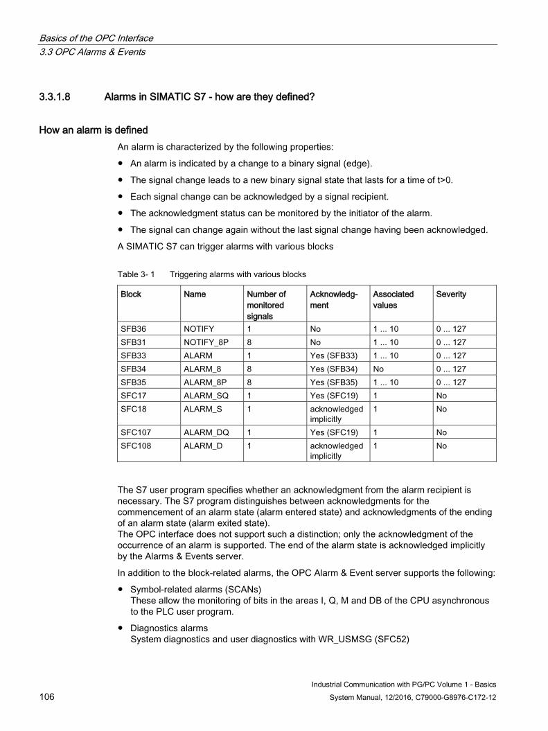
Basics of the OPC Interface 3.3 OPC Alarms & Events
Industrial Communication with PG/PC Volume 1 - Basics 106 System Manual, 12/2016, C79000-G8976-C172-12
3.3.1.8 Alarms in SIMATIC S7 - how are they defined?
How an alarm is defined An alarm is characterized by the following properties:
● An alarm is indicated by a change to a binary signal (edge).
● The signal change leads to a new binary signal state that lasts for a time of t>0.
● Each signal change can be acknowledged by a signal recipient.
● The acknowledgment status can be monitored by the initiator of the alarm.
● The signal can change again without the last signal change having been acknowledged.
A SIMATIC S7 can trigger alarms with various blocks
Table 3- 1 Triggering alarms with various blocks
Block Name Number of monitored signals
Acknowledg-ment
Associated values
Severity
SFB36 NOTIFY 1 No 1 ... 10 0 ... 127 SFB31 NOTIFY_8P 8 No 1 ... 10 0 ... 127 SFB33 ALARM 1 Yes (SFB33) 1 ... 10 0 ... 127 SFB34 ALARM_8 8 Yes (SFB34) No 0 ... 127 SFB35 ALARM_8P 8 Yes (SFB35) 1 ... 10 0 ... 127 SFC17 ALARM_SQ 1 Yes (SFC19) 1 No SFC18 ALARM_S 1 acknowledged
implicitly 1 No
SFC107 ALARM_DQ 1 Yes (SFC19) 1 No SFC108 ALARM_D 1 acknowledged
implicitly 1 No
The S7 user program specifies whether an acknowledgment from the alarm recipient is necessary. The S7 program distinguishes between acknowledgments for the commencement of an alarm state (alarm entered state) and acknowledgments of the ending of an alarm state (alarm exited state). The OPC interface does not support such a distinction; only the acknowledgment of the occurrence of an alarm is supported. The end of the alarm state is acknowledged implicitly by the Alarms & Events server.
In addition to the block-related alarms, the OPC Alarm & Event server supports the following:
● Symbol-related alarms (SCANs) These allow the monitoring of bits in the areas I, Q, M and DB of the CPU asynchronous to the PLC user program.
● Diagnostics alarms System diagnostics and user diagnostics with WR_USMSG (SFC52)
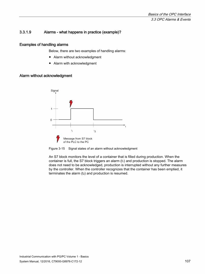
Basics of the OPC Interface 3.3 OPC Alarms & Events
Industrial Communication with PG/PC Volume 1 - Basics System Manual, 12/2016, C79000-G8976-C172-12 107
3.3.1.9 Alarms - what happens in practice (example)?
Examples of handling alarms Below, there are two examples of handling alarms:
● Alarm without acknowledgment
● Alarm with acknowledgment
Alarm without acknowledgment
Figure 3-15 Signal states of an alarm without acknowledgment
An S7 block monitors the level of a container that is filled during production. When the container is full, the S7 block triggers an alarm (t1) and production is stopped. The alarm does not need to be acknowledged, production is interrupted without any further measures by the controller. When the controller recognizes that the container has been emptied, it terminates the alarm (t2) and production is resumed.
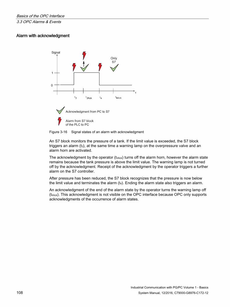
Basics of the OPC Interface 3.3 OPC Alarms & Events
Industrial Communication with PG/PC Volume 1 - Basics 108 System Manual, 12/2016, C79000-G8976-C172-12
Alarm with acknowledgment
Figure 3-16 Signal states of an alarm with acknowledgment
An S7 block monitors the pressure of a tank. If the limit value is exceeded, the S7 block triggers an alarm (t3), at the same time a warning lamp on the overpressure valve and an alarm horn are activated.
The acknowledgment by the operator (t3Ack) turns off the alarm horn, however the alarm state remains because the tank pressure is above the limit value. The warning lamp is not turned off by the acknowledgment. Receipt of the acknowledgment by the operator triggers a further alarm on the S7 controller.
After pressure has been reduced, the S7 block recognizes that the pressure is now below the limit value and terminates the alarm (t4). Ending the alarm state also triggers an alarm.
An acknowledgment of the end of the alarm state by the operator turns the warning lamp off (t4Ack). This acknowledgment is not visible on the OPC interface because OPC only supports acknowledgments of the occurrence of alarm states.

Basics of the OPC Interface 3.3 OPC Alarms & Events
Industrial Communication with PG/PC Volume 1 - Basics System Manual, 12/2016, C79000-G8976-C172-12 109
3.3.2 Alarms & Events Interface
3.3.2.1 Interfaces - which interfaces are specified for Alarms & Events?
For Alarms & Events two interfaces are specified For Alarms & Events the automation and custom interfaces are specified:
● Alarms & Events Automation Interface, Standard, December 15, 1999, Version 1.01 Description of the OPC Alarms & Events server as well as the specification of the Custom Interface of this server
● OPC Alarms & Events Custom Interface, October 2, 2002, Version 1.10 Specification of the Automation Interface of the OPC Alarms & Events server
You will find an overview of the specifications in the list of references of volume 2.
Basics of the OPC Interface 3.4 OPC XML
Industrial Communication with PG/PC Volume 1 - Basics 110 System Manual, 12/2016, C79000-G8976-C172-12
3.4 OPC XML
3.4.1 Introduction to XML and SOAP
3.4.1.1 XML and SOAP - what are they?
OPC goes Internet By using the OPC XML data access interface, process data can also be read, written and, in simple form, also monitored over the Internet.
For this, OPC uses SOAP.
What is SOAP? SOAP provides a simple and transparent mechanism for the exchange of structured and typed information between computers in a distributed environment.
The "Simple Object Access Protocol" (SOAP) forms the basis for XML-based information exchange.
What is XML and OPC XML? XML (eXtensible Markup Language) is a standard for the Internet that has also become widespread in other areas of standard software. Just like HTML, XML also provides the option of including metainformation with data. It is, however, possible with XML to define your own data structures and your own attributes.
Based on XML, a new specification was also defined for OPC known as OPC XML, that describes the process data interface with XML data records.
How does access to OPC over the Internet work? Communication over the DCOM interfaces of OPC is normally restricted to local area networks. COM interfaces are also normally defined for Windows-based systems. For security purposes, firewalls only allow restricted access to and from the Internet. OPC XML makes a standard available that allows communication using the cross-platform protocol SOAP (Simple Object Access Protocol). Data access with OPC XML has a range of functions based on OPC Data Access.
What does the interface description look like with XML? The data interfaces and methods are described by XML. The precise description of the methods is specified in a WSDL specification (WSDL = Web Service Definition Language) provided by the OPC Foundation along with the OPC XML DA specification. The methods are described with SOAP (XML protocol) and sent using the HTTP protocol. Put simply, we can say the following:
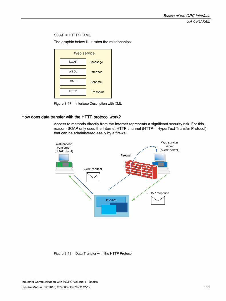
Basics of the OPC Interface 3.4 OPC XML
Industrial Communication with PG/PC Volume 1 - Basics System Manual, 12/2016, C79000-G8976-C172-12 111
SOAP = HTTP + XML
The graphic below illustrates the relationships:
Figure 3-17 Interface Description with XML
How does data transfer with the HTTP protocol work? Access to methods directly from the Internet represents a significant security risk. For this reason, SOAP only uses the Internet HTTP channel (HTTP = HyperText Transfer Protocol) that can be administered easily by a firewall.
Figure 3-18 Data Transfer with the HTTP Protocol
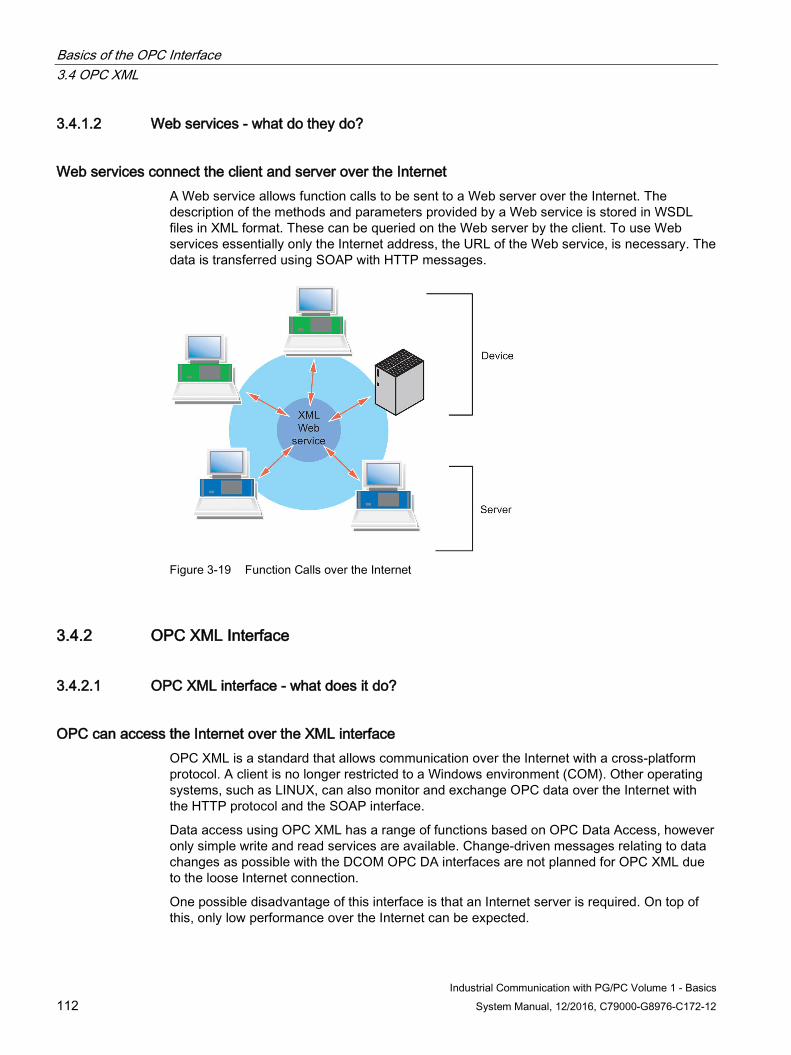
Basics of the OPC Interface 3.4 OPC XML
Industrial Communication with PG/PC Volume 1 - Basics 112 System Manual, 12/2016, C79000-G8976-C172-12
3.4.1.2 Web services - what do they do?
Web services connect the client and server over the Internet A Web service allows function calls to be sent to a Web server over the Internet. The description of the methods and parameters provided by a Web service is stored in WSDL files in XML format. These can be queried on the Web server by the client. To use Web services essentially only the Internet address, the URL of the Web service, is necessary. The data is transferred using SOAP with HTTP messages.
Figure 3-19 Function Calls over the Internet
3.4.2 OPC XML Interface
3.4.2.1 OPC XML interface - what does it do?
OPC can access the Internet over the XML interface OPC XML is a standard that allows communication over the Internet with a cross-platform protocol. A client is no longer restricted to a Windows environment (COM). Other operating systems, such as LINUX, can also monitor and exchange OPC data over the Internet with the HTTP protocol and the SOAP interface.
Data access using OPC XML has a range of functions based on OPC Data Access, however only simple write and read services are available. Change-driven messages relating to data changes as possible with the DCOM OPC DA interfaces are not planned for OPC XML due to the loose Internet connection.
One possible disadvantage of this interface is that an Internet server is required. On top of this, only low performance over the Internet can be expected.
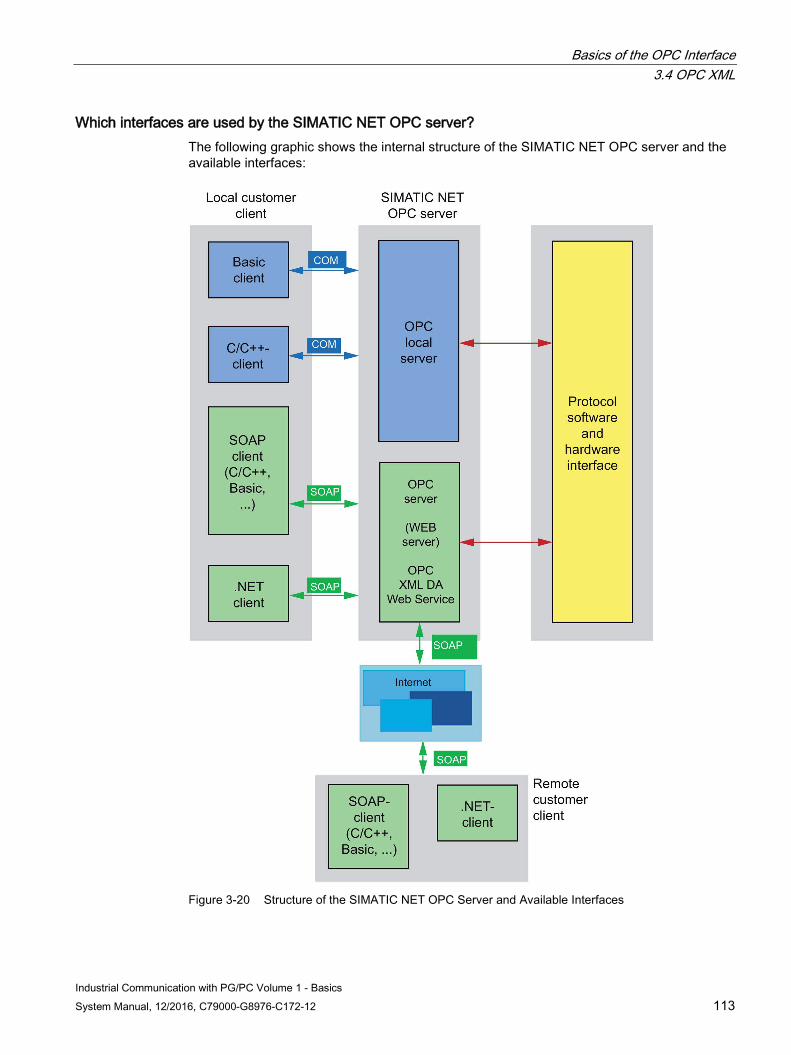
Basics of the OPC Interface 3.4 OPC XML
Industrial Communication with PG/PC Volume 1 - Basics System Manual, 12/2016, C79000-G8976-C172-12 113
Which interfaces are used by the SIMATIC NET OPC server? The following graphic shows the internal structure of the SIMATIC NET OPC server and the available interfaces:
Figure 3-20 Structure of the SIMATIC NET OPC Server and Available Interfaces
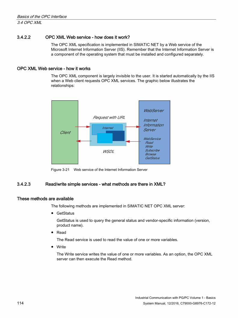
Basics of the OPC Interface 3.4 OPC XML
Industrial Communication with PG/PC Volume 1 - Basics 114 System Manual, 12/2016, C79000-G8976-C172-12
3.4.2.2 OPC XML Web service - how does it work? The OPC XML specification is implemented in SIMATIC NET by a Web service of the Microsoft Internet Information Server (IIS). Remember that the Internet Information Server is a component of the operating system that must be installed and configured separately.
OPC XML Web service - how it works The OPC XML component is largely invisible to the user. It is started automatically by the IIS when a Web client requests OPC XML services. The graphic below illustrates the relationships:
Figure 3-21 Web service of the Internet Information Server
3.4.2.3 Read/write simple services - what methods are there in XML?
These methods are available The following methods are implemented in SIMATIC NET OPC XML server:
● GetStatus
GetStatus is used to query the general status and vendor-specific information (version, product name).
● Read
The Read service is used to read the value of one or more variables.
● Write
The Write service writes the value of one or more variables. As an option, the OPC XML server can then execute the Read method.
Basics of the OPC Interface 3.4 OPC XML
Industrial Communication with PG/PC Volume 1 - Basics System Manual, 12/2016, C79000-G8976-C172-12 115
● Subscription, SubscriptionPolledRefresh, SubscriptionCancel
With subscriptions, the variables are registered and any changes (cyclic) read with SubscriptionPolledRefresh. A subscription can be canceled with SubscriptionCancel.
One special feature of SubscriptionPolledRefresh is the time when the specified with WaitTime and HoldTime. The call on the server is held back until WaitTime. The response to the call is sent as soon as a value changes or at the latest when HoldTime is reached.
● Browse
The Browse service allows navigation through the hierarchical address space. In contrast to the COM interface, both branches and leaves can be read with a request.
It is also possible to specify which properties of an element the server returns.
● GetProperties
As an alternative to browsing, properties of elements can also be read with the GetProperties service
Synchronous/Asynchronous Use of the Methods These methods are designed to operate asynchronously according to the OPC XML DA specification. Request and response are separate parts of the protocol. The use of these methods by high-level programming languages such as C#, Visual Basic etc. allows the request and response to be combined to form a synchronous method.
When creating a proxy class for the client program, a synchronous and an asynchronous variant are generated for each method. Both variants use the same OPC XML DA methods. Using the asynchronous variant does, however, improve the runtime response of the client program.
For more detailed information, refer to /1/
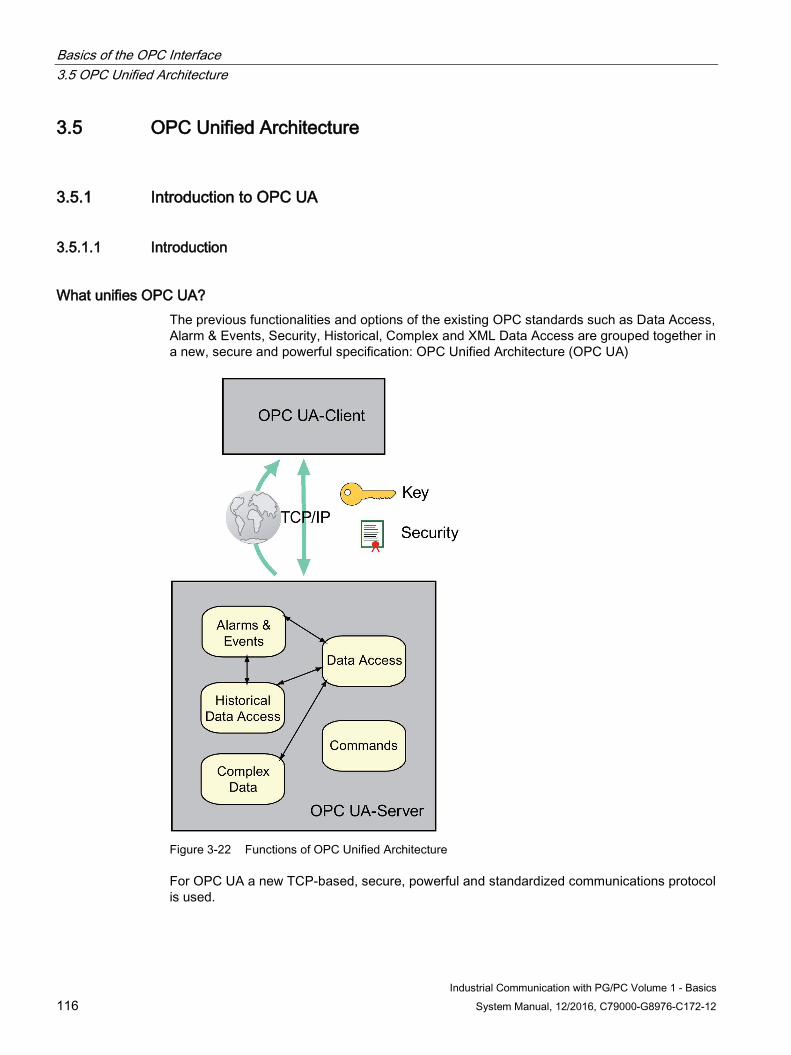
Basics of the OPC Interface 3.5 OPC Unified Architecture
Industrial Communication with PG/PC Volume 1 - Basics 116 System Manual, 12/2016, C79000-G8976-C172-12
3.5 OPC Unified Architecture
3.5.1 Introduction to OPC UA
3.5.1.1 Introduction
What unifies OPC UA? The previous functionalities and options of the existing OPC standards such as Data Access, Alarm & Events, Security, Historical, Complex and XML Data Access are grouped together in a new, secure and powerful specification: OPC Unified Architecture (OPC UA)
Figure 3-22 Functions of OPC Unified Architecture
For OPC UA a new TCP-based, secure, powerful and standardized communications protocol is used.
Basics of the OPC Interface 3.5 OPC Unified Architecture
Industrial Communication with PG/PC Volume 1 - Basics System Manual, 12/2016, C79000-G8976-C172-12 117
What are the advantages of the OPC UA architecture? ● Unification of the previous OPC standards in one interface.
This simplifies the development of client applications.
● The UA namespace provides the option of the complete modeling of systems of any complexity. It has a significantly greater range of functions than the previous namespace.
What are the advantages of OPC UA communication compared with the COM/DCOM interface? ● Platform independent communication
● Greater security thanks to independence from DOM:
– No complex security settings
– No open port 135
– No further dynamically assigned ports
– Easier setting of the firewall
– No long timeouts with disturbances
● High data security thanks to modern authentication procedures based on certificates
● Selection of different communication protocols suitable for the particular applicatopn
3.5.1.2 Security with OPC UA
How is security ensured? An OPC UA client and an OPC UA server need to authenticate and authorize each other with digital certificates and corresponding keys. The messages are encrypted accordingly. For the authentication X.509 certificates are used.
An OPC UA client application is normally assigned a certificate store. Keys of authorized OPC UA servers can be stored there.
To manage the certificates, the SIMATIC NET OPC UA server uses a target system-specific Public Key Infrastructure (PKI) on the client.
3.5.1.3 Types of communication of OPC UA
What do the OPC UA communication types "TCP binary" and "XML" involve? At the lowest level, the communications protocol of OPC UA is TCP-based and can therefore be used cross-platform even on embedded systems. A secure, encrypted transmission is required in all cases.
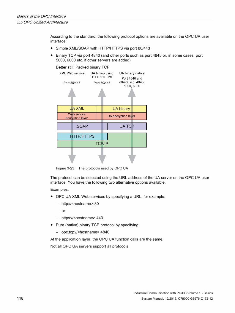
Basics of the OPC Interface 3.5 OPC Unified Architecture
Industrial Communication with PG/PC Volume 1 - Basics 118 System Manual, 12/2016, C79000-G8976-C172-12
According to the standard, the following protocol options are available on the OPC UA user interface:
● Simple XML/SOAP with HTTP/HTTPS via port 80/443
● Binary TCP via port 4840 (and other ports such as port 4845 or, in some cases, port 5000, 6000 etc. if other servers are added)
Better still: Packed binary TCP
Figure 3-23 The protocols used by OPC UA
The protocol can be selected using the URL address of the UA server on the OPC UA user interface. You have the following two alternative options available.
Examples:
● OPC UA XML Web services by specifying a URL, for example:
– http://<hostname>:80
or
– https://<hostname>:443
● Pure (native) binary TCP protocol by specifying:
– opc.tcp://<hostname>:4840
At the application layer, the OPC UA function calls are the same.
Not all OPC UA servers support all protocols.
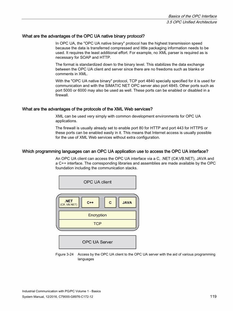
Basics of the OPC Interface 3.5 OPC Unified Architecture
Industrial Communication with PG/PC Volume 1 - Basics System Manual, 12/2016, C79000-G8976-C172-12 119
What are the advantages of the OPC UA native binary protocol? In OPC UA, the "OPC UA native binary" protocol has the highest transmission speed because the data is transferred compressed and little packaging information needs to be used. It requires the least additional effort. For example, no XML parser is required as is necessary for SOAP and HTTP.
The format is standardized down to the binary level. This stabilizes the data exchange between the OPC UA client and server since there are no freedoms such as blanks or comments in XML.
With the "OPC UA native binary" protocol, TCP port 4840 specially specified for it is used for communication and with the SIMATIC NET OPC server also port 4845. Other ports such as port 5000 or 6000 may also be used as well. These ports can be enabled or disabled in a firewall.
What are the advantages of the protocols of the XML Web services? XML can be used very simply with common development environments for OPC UA applications.
The firewall is usually already set to enable port 80 for HTTP and port 443 for HTTPS or these ports can be enabled easily in it. This means that Internet access is usually possible for the use of XML Web services without extra configuration.
Which programming languages can an OPC UA application use to access the OPC UA interface? An OPC UA client can access the OPC UA interface via a C, .NET (C#,VB.NET), JAVA and a C++ interface. The corresponding libraries and assemblies are made available by the OPC foundation including the communication stacks.
Figure 3-24 Access by the OPC UA client to the OPC UA server with the aid of various programming
languages
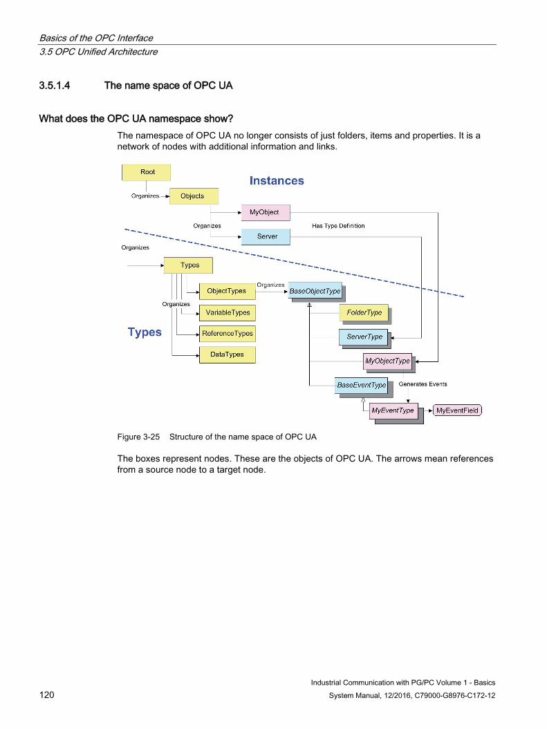
Basics of the OPC Interface 3.5 OPC Unified Architecture
Industrial Communication with PG/PC Volume 1 - Basics 120 System Manual, 12/2016, C79000-G8976-C172-12
3.5.1.4 The name space of OPC UA
What does the OPC UA namespace show? The namespace of OPC UA no longer consists of just folders, items and properties. It is a network of nodes with additional information and links.
Figure 3-25 Structure of the name space of OPC UA
The boxes represent nodes. These are the objects of OPC UA. The arrows mean references from a source node to a target node.
Basics of the OPC Interface 3.5 OPC Unified Architecture
Industrial Communication with PG/PC Volume 1 - Basics System Manual, 12/2016, C79000-G8976-C172-12 121
The nodes are used both for the user data (instances) and for other information such as type descriptions of data (types). The nodes of OPC UA can be subdivided as follows:
● Types
These are node types specified in the OPC UA specification and possibly also by the relevant vendor and they are uniquely defined in terms of their properties and attributes. There are four basic types as follows:
– ObjectTypes
– VariableTypes
– ReferenceTypes
– DataTypes
They define other types, some of which are shown in the figure to the right of the "ObjectTypes" type.
The types serve as a type description for the instances.
● Instances
These are the instances of the objects of your real project. Depending on the type of node, they obtain their properties by referencing the various types. In the figure, the two objects "MyObject" and "Server" reference the two types "MyObjectType" and "ServerType".
The root of your OPC-UA-Servers organizes both the types and the instances. This organizing includes the definition of the other nodes.
A node can have the following properties:
● Attributes that can be read
● Methods that can be called
● Events that can be reported
Many standard nodes are specified in the OPC UA specification. Other node types of specific vendors can be added. The namespace is displayed in the OPC Scout V10 in a tree structure.
Locating OPC UA servers on a system with "Discovery" The OPC UA search service "Discovery" allows OPC UA servers in a system to be located. This discovery service uses port 4840 that is reserved for OPC UA, the host name and/or the IP address. It reports the endpoints of all OPC UA servers, their protocols, ports and security requirements.
Endpoints of the OPC UA server An OPC UA server provides endpoints for communication.
An endpoint is the physical address in a network that allows OPC UA clients to access one or more services of the OPC UA server.
You will find details of the endpoints of the OPC UA server in volume 2 of this manual in the Manual Collection of the "SIMATIC NET PC Software" DVD.
Basics of the OPC Interface 3.5 OPC Unified Architecture
Industrial Communication with PG/PC Volume 1 - Basics 122 System Manual, 12/2016, C79000-G8976-C172-12
3.5.1.5 Other characteristics of OPC UA
What can OPC UA do apart from this? OPC UA also provides a series of other functions, some of which will be briefly introduced:
● Redundancy
Between several OPC UA clients and several OPC UA servers OPC UA provides redundancy functions ranging from the simple adoption of sessions between OPC UA clients to coordinated redundancy between OPC UA servers.
● Connection monitoring
An OPC UA server detects interrupted connections to the OPC UA client and an OPC UA client detects interrupted connections to the OPC UA server. The monitoring times are specified in the standard.
● Data value storage
Interrupted connections do not generally lead to loss of data. The data values are stored. Data not correctly received can be requested again. The receipt of data can be acknowledged.
Basics of the OPC Interface 3.5 OPC Unified Architecture
Industrial Communication with PG/PC Volume 1 - Basics System Manual, 12/2016, C79000-G8976-C172-12 123
3.5.2 The OPC UA interface
3.5.2.1 What interface specifications of the OPC Unified Architecture exist?
Which interface specifications of the OPC Unified Architecture are there? The OPC UA specification consists of several parts. These are service specifications.
The user interface is specified by the language-dependent OPC UA server stack made available by the OPC Foundation or the OPC UA user libraries. The specification is made up of the following parts:
Part Topic Title URL Part 1 Concepts OPC UA Specification: Part 1 – Con-
cepts, Version 1.0 or later http://www.opcfoundation.org/UA/Part1
Part 2 Security Model OPC UA Specification: Part 2 – Security Model, Version 1.0 or later
http://www.opcfoundation.org/UA/Part2
Part 3 Address Space Model OPC UA Specification: Part 3 – Address Space Model, Version 1.0 or later
http://www.opcfoundation.org/UA/Part3
Part 4 Services OPC UA Specification: Part 4 – Ser-vices, Version 1.0 or later
http://www.opcfoundation.org/UA/Part4
Part 5 Information Model OPC UA Specification: Part 5 – Infor-mation Model, Version 1.0 or later
http://www.opcfoundation.org/UA/Part5
Part 6 Service Mappings OPC UA Specification: Part 6 – Map-ping, Version 1.0 or later
http://www.opcfoundation.org/UA/Part6
Part 7 Profiles OPC UA Specification: Part 7 – Profiles, Version 1.0 or later
http://www.opcfoundation.org/UA/Part7
Part 8 Data Access OPC UA Specification: Part 8 – Data Access, Version 1.0 or later
http://www.opcfoundation.org/UA/Part8
Part 9 Alarms and Conditions OPC UA Specification: Part 9 – Alarms and Conditions, Version 1.0 or later
http://www.opcfoundation.org/UA/Part9
Part 10 Programs OPC UA Specification: Part 10 – Pro-grams, Version 1.0 or later
http://www.opcfoundation.org/UA/Part10
Part 11 Historical Access OPC UA Specification: Part 11 – Histor-ical Access, Version 1.0 or later
http://www.opcfoundation.org/UA/Part11
Part 12 Discovery OPC UA Specification: Part 12 – Dis-covery, Version 1.0 or later
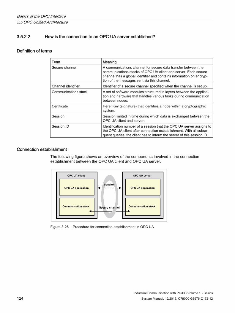
Basics of the OPC Interface 3.5 OPC Unified Architecture
Industrial Communication with PG/PC Volume 1 - Basics 124 System Manual, 12/2016, C79000-G8976-C172-12
3.5.2.2 How is the connection to an OPC UA server established?
Definition of terms Term Meaning Secure channel A communications channel for secure data transfer between the
communications stacks of OPC UA client and server. Each secure channel has a global identifier and contains information on encryp-tion of the messages sent via this channel.
Channel identifier Identifier of a secure channel specified when the channel is set up. Communications stack A set of software modules structured in layers between the applica-
tion and hardware that handles various tasks during communication between nodes.
Certificate Here: Key (signature) that identifies a node within a cryptographic system.
Session Session limited in time during which data is exchanged between the OPC UA client and server.
Session ID Identification number of a session that the OPC UA server assigns to the OPC UA client after connection estsablishment. With all subse-quent queries, the client has to inform the server of this session ID.
Connection establishment The following figure shows an overview of the components involved in the connection establishment between the OPC UA client and OPC UA server.
Figure 3-26 Procedure for connection establishment in OPC UA
Basics of the OPC Interface 3.5 OPC Unified Architecture
Industrial Communication with PG/PC Volume 1 - Basics System Manual, 12/2016, C79000-G8976-C172-12 125
The following steps are run through during connection establishment:
1. Setup of a secure channel
To set up a secure channel the service "OpenSecureChannel" is used.
This service opens or renews a secure channel during a session. The secure channel allows the confidential transfer of information between OPC UA client and server.
After a secure channel has been set up the communications stack uses the various security algorithms for the frames to be sent, After signing by the certificate of the sender, the frames are transferred encrypted, Only authorized partners can decrypt the frame.
2. Establishment of a session
To establish a session, the service "CreateSession" is used.
With the aid of this service the OPC UA client establishes a session. The OPC UA server returns the session ID.
With the following queries of the client, the server only accepts the query when the client transfers both the channel ID and the session ID.
3.5.2.3 How can the OPC UA namespace be browsed?
How can the OPC UA namespace be browsed? To browse the OPC UA namespace, the following services are available:
● "Browse"
This service is used to determine the references (links) of a node.
● "Read"
This service is used to determine one or more attributes of one or more nodes.
The response supplies the value being looked for (reference, property or attribute).
Basics of the OPC Interface 3.5 OPC Unified Architecture
Industrial Communication with PG/PC Volume 1 - Basics 126 System Manual, 12/2016, C79000-G8976-C172-12
3.5.2.4 How can data be read and written?
How is simple reading and writing achieved? The two services "Read" and "Write" are available to read and write the attribute values of nodes.
● "Read"
This service is used to obtain one or more attributes of one or more nodes. With structured attribute values, whose elements are indexed as in an array, clients can read the entire set of indexed values, they can read specific areas or individual elements.
How up-to-date the values are is decided by the "maxAge" parameter.
● "Write"
This service is used to write values to one or more attributes of one or more nodes. With structured attribute values, whose elements are indexed as in an array, clients can write the entire set of indexed values, they can write specific areas or individual elements.
The service job remains pending until the values have been written or until it is recognized that the values cannot be written.
Access by "Read" and "Write" uses the "NodeID" of the node or nodes. The NodeID is the identifier of a node in the name space of OPC UA.
3.5.2.5 How are UA data and events monitored?
Definition of terms Term Meaning Subscription A subscription is used for the data transfer from the OPC UA server
to the client. A subscription contains a set of monitored items that are transferred to the client in a notification.
Monitored item A client defines monitored items for acquisition of data and events. A monitored item identifies an item to be monitored, its corresponding subscription and the notification for transfer of the the data by the subscription.
Item An item can be any node attribute. Notification A data structure that describes changes to data values or events.
This data structure is filled with the data of the monitored items. Notification message For the transfer to the client a notification is packed in a notification
message by the subscription. Publish Request A request from the client to the server to transfer data Attribute A simple characteristic of a node defined by the OPC UA specifica-
tion. Node / NodeID
A node is a fundamental component of the namespace. Each node is identified by its NodeID.
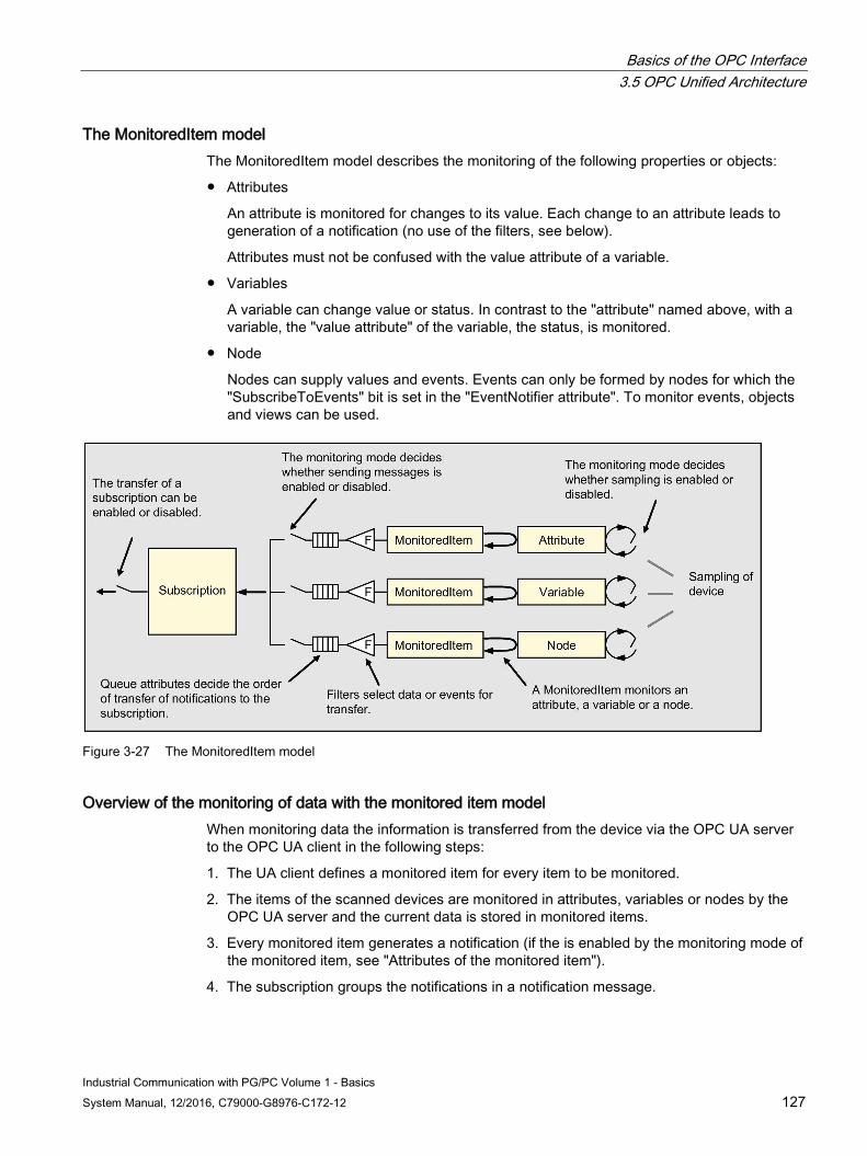
Basics of the OPC Interface 3.5 OPC Unified Architecture
Industrial Communication with PG/PC Volume 1 - Basics System Manual, 12/2016, C79000-G8976-C172-12 127
The MonitoredItem model The MonitoredItem model describes the monitoring of the following properties or objects:
● Attributes
An attribute is monitored for changes to its value. Each change to an attribute leads to generation of a notification (no use of the filters, see below).
Attributes must not be confused with the value attribute of a variable.
● Variables
A variable can change value or status. In contrast to the "attribute" named above, with a variable, the "value attribute" of the variable, the status, is monitored.
● Node
Nodes can supply values and events. Events can only be formed by nodes for which the "SubscribeToEvents" bit is set in the "EventNotifier attribute". To monitor events, objects and views can be used.
Figure 3-27 The MonitoredItem model
Overview of the monitoring of data with the monitored item model When monitoring data the information is transferred from the device via the OPC UA server to the OPC UA client in the following steps:
1. The UA client defines a monitored item for every item to be monitored.
2. The items of the scanned devices are monitored in attributes, variables or nodes by the OPC UA server and the current data is stored in monitored items.
3. Every monitored item generates a notification (if the is enabled by the monitoring mode of the monitored item, see "Attributes of the monitored item").
4. The subscription groups the notifications in a notification message.
Basics of the OPC Interface 3.5 OPC Unified Architecture
Industrial Communication with PG/PC Volume 1 - Basics 128 System Manual, 12/2016, C79000-G8976-C172-12
5. The subscription transfers the notification message to the client.
6. The client acknowledges receipt of the notification message.
The attributes of MonitoredItems The MonitoredItem has four attributes with the following functions:
● The sampling interval
Each MonitoredItem generated by the client has a sampling interval assigned to it. The sampling interval specifies the shortest interval at which the server samples the lower-level data source (the device).
The sampling interval is either inherited from the publishing interval of the subscription (see below) or it is individually configured to overwrite the publishing interval. As default, the sampling interval has the value of the publishing interval.
● The monitoring mode
The monitoring mode specifies whether the sampling and transfer of notifications is enabled or disabled.
● The filter
The filter defines the magnitude of the change as of which a value or event is transferred. A filter can also filter the properties of the "EventType" of an event, such as EventID, EventType, SourceNode, Time and Description.
No filters are applied to attributes since every change to an attribute generates a notification.
The filter also detects whether an event derived from a node was sent to the client.
● The queue attributes
The queue attributes can be used to specify the order of transfer to the client.
Data transmission with the subscription A subscription is used to transfer notifications to the client.
A subscription has one or more MonitoredItems assigned to it by the client. MonitoredItems generate notifications that are packed into NotificationMessages by the subscription. One or more NotificationMessages are transferred by a subscription to the client.
Basics of the OPC Interface 3.5 OPC Unified Architecture
Industrial Communication with PG/PC Volume 1 - Basics System Manual, 12/2016, C79000-G8976-C172-12 129
A subscription is created with the "CreateSubscription" service. This has the following characteristics:
● Publishing interval
A subscription has a publishing interval that decides the cycle at which the subscription becomes active. Within this publishing cycle, the subscription attempts to send a NotificationMessage to the client.
NotificationMessages contain notifications that have not yet been sent to the client.
● Answer to a "Publish Request"
NotificationMessages are sent as a response to a publish request to the client. As soon as a publish request is received from the server, the publish request is entered in the queue of the session.
– When a notification is ready for transfer, the publish request is removed from the queue and processed by the subscription that belongs to the current session.
– If there is no notification ready for transfer, the publish request is not removed from the queue of the session and the server waits until the next cycle and then checks whether there is a notification.
At the start of a cycle when notifications are present but there is not yet a publish request, the server changes to the state waiting for publish requests. As soon as a publish request is received, this is processed immediately without waiting for the next publishing interval.
● Sequence number of the NotificationMessage (missing messages)
Each NotificationMessage has an individual sequence number that allows clients to recognize when messages are missing.
● Keep-alive counter
Subscriptions have a keep-alive counter that counts the number of consecutive cycles in which no notification was ready for transfer. When the maximum selectable value of the counter is reached, the publish request is removed from the queue and used to send a keep-alive message. The keep-alive message informs the client that the server is still active.
A keep-alive message is the response to a publish request, in which the NotificationMessage does not contain a notification but rather the sequence number of the NotificationMessage that will be sent next.
● Enabling the "Publishing" service
The "Publishing" service of a subscription can be enabled or disabled by the client when the subscription is created. As an alternative, "Publishing" can also be enabled/disabled using the "SetPublishingMode" service.
When it is disabled, the subscription does not send any NotificationMessages to the client, it nevertheless becomes active cyclically and sends keep-alive messages to the client.

Basics of the OPC Interface 3.5 OPC Unified Architecture
Industrial Communication with PG/PC Volume 1 - Basics 130 System Manual, 12/2016, C79000-G8976-C172-12
● Lifetime counter
Subscriptions have a lifetime counter that counts the number of consecutive publishing cycles in which there was no publish request of the client. When the counter reaches the value calculated for the lifetime of a subscription based on the "MaxKeepAliveCount" parameter of the "CreateSubscription" service, the subscription is closed.
Closing a subscription deletes its MonitoredItem. The server also sends a NotificationMessage "StatusChangeNotification" with the status "code Bad_Timeout".
● Acknowledging the NotificationMessage and notification buffer
Subscriptions have a buffer for repeated transfer of NotificationMessages. NotificationMessages are retained in this buffer until they are acknowledged by the client, at least, however, for 1 keep-alive interval.
The "Publish" service The "Publish" service has two purposes:
● Requesting the server to send a NotificationMessage or a keep-alive message
● Acknowledgment of receipt of NotificationMessages for one or more subscriptions
Since publish requests are not addressed to specific subscriptions, they can be used by any subscription.
3.5.2.6 How is extra fast reading and writing achieved after registration?
How is extra fast reading and writing achieved after registration? To read and write the attribute values of registered nodes quickly, the methods "Read(..,handle,..)" and "Write(..,handle,..)" are available after registration of the relevant nodes. With these methods, a brief call of the registered nodes is possible allowing a time-saving data transfer. Access is via the NodeID of the registered nodes.
Reading / writing follows the steps below:
1. RegisterNodes()
2. Read(..,handle,..)
Write(..,handle,..)
3. UnregisterNodes()
The functionality of the "RegisterNodes" method is comparable with the functionality of the "AddItems" method in OPC Data Access.
Basics of the OPC Interface 3.5 OPC Unified Architecture
Industrial Communication with PG/PC Volume 1 - Basics System Manual, 12/2016, C79000-G8976-C172-12 131
3.5.2.7 How do events, conditions and alarms work? This section describes events, conditions and alarms.
Events Events describe special states in the process that need to be reported to a recipient. The events reported to the OPC client are selected by the OPC client using filter criteria.
OPC UA events differ from the events on the previous COM interface OPC Alarms & Events in that the the same access techniques and interfaces are used for OPC UA events as for UA data access.
Conditions Conditions are derived from the general events. Conditions are used to represent the status of a system or one of its components. A few examples are shown below:
● A temperature exceeds a configured value.
● A device requires maintenance.
● A batch process requires confirmation by the user before continuing with the next process steps.
The primary states of conditions are "enabled" and "disabled". The "disabled" state is used to turn off the conditions via the server. The "enabled" state is generally expanded by additional sub-states.
Changing to the "disabled" state results in a condition event. However no further event alarms are generated until the condition changes back to the "enabled" state.
When a condition changes to the "enabled" state, this change and all subsequent changes lead to the server generating condition events.
The condition is significant for the "enabled" state. The OPC server and the device process the condition.
The condition is not significant for the "disabled" state. The OPC server and the device do not need to process the condition, there are no "Events" alarms for this condition.
Acknowledgment The AcknowledgeableConditionType type is derived from the ConditionType type. It contains a sub-state of a condition to indicate whether or not a condition needs to be acknowledged.
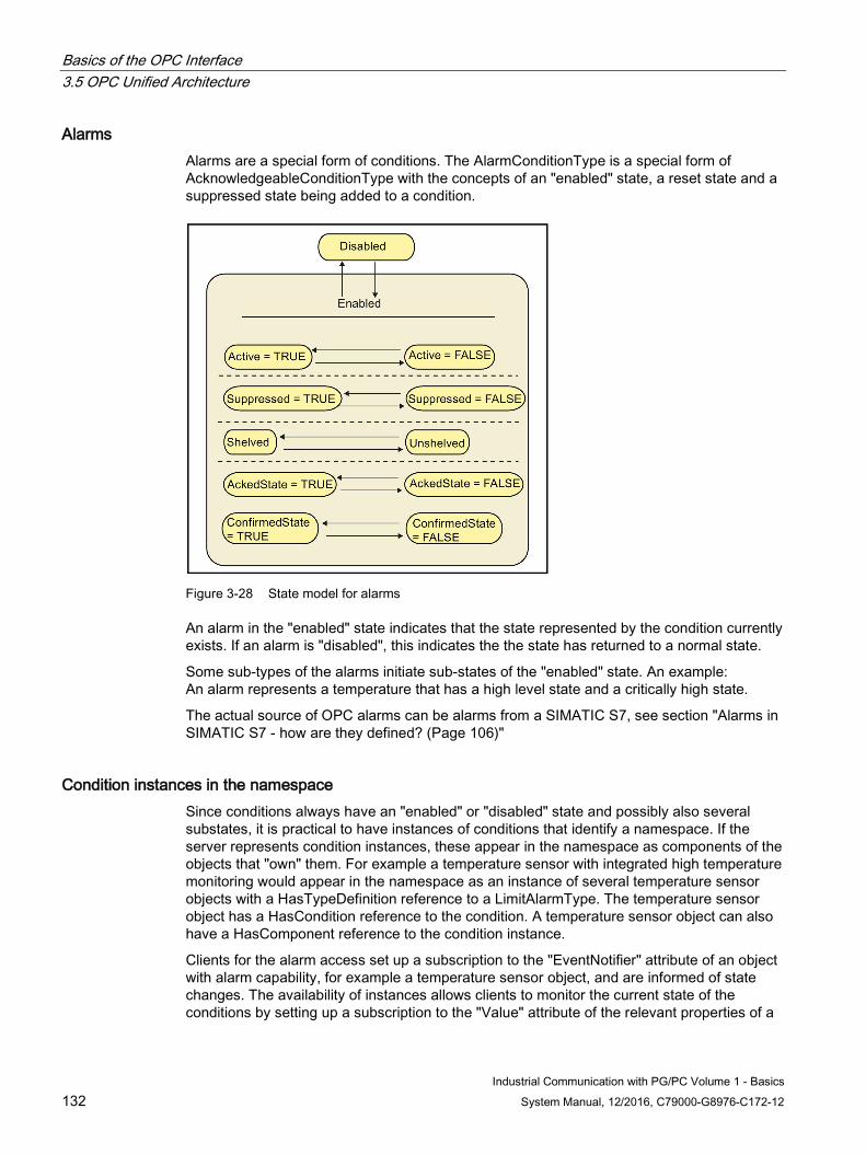
Basics of the OPC Interface 3.5 OPC Unified Architecture
Industrial Communication with PG/PC Volume 1 - Basics 132 System Manual, 12/2016, C79000-G8976-C172-12
Alarms Alarms are a special form of conditions. The AlarmConditionType is a special form of AcknowledgeableConditionType with the concepts of an "enabled" state, a reset state and a suppressed state being added to a condition.
Figure 3-28 State model for alarms
An alarm in the "enabled" state indicates that the state represented by the condition currently exists. If an alarm is "disabled", this indicates the the state has returned to a normal state.
Some sub-types of the alarms initiate sub-states of the "enabled" state. An example: An alarm represents a temperature that has a high level state and a critically high state.
The actual source of OPC alarms can be alarms from a SIMATIC S7, see section "Alarms in SIMATIC S7 - how are they defined? (Page 106)"
Condition instances in the namespace Since conditions always have an "enabled" or "disabled" state and possibly also several substates, it is practical to have instances of conditions that identify a namespace. If the server represents condition instances, these appear in the namespace as components of the objects that "own" them. For example a temperature sensor with integrated high temperature monitoring would appear in the namespace as an instance of several temperature sensor objects with a HasTypeDefinition reference to a LimitAlarmType. The temperature sensor object has a HasCondition reference to the condition. A temperature sensor object can also have a HasComponent reference to the condition instance.
Clients for the alarm access set up a subscription to the "EventNotifier" attribute of an object with alarm capability, for example a temperature sensor object, and are informed of state changes. The availability of instances allows clients to monitor the current state of the conditions by setting up a subscription to the "Value" attribute of the relevant properties of a
Basics of the OPC Interface 3.5 OPC Unified Architecture
Industrial Communication with PG/PC Volume 1 - Basics System Manual, 12/2016, C79000-G8976-C172-12 133
condition instance. In this case, it is, however, possible that this client is not informed of all state changes.
Even if it is not always possible to offer condition instances in the namespace, this mechanism allows direct access (read, write and method call) for the specific condition instance. For example if a condition instance is not displayed, there is no way of calling the enabling or disabling method for the special condition instance.
For further information, refer to section OPC Alarms & Events (Page 100)
How can events, conditions and alarms be received? A UA client can use the same technologies for receiving events as for monitoring data. The namespace can be browsed, nodes with the references HasNotifier, HasEventSource and HasCondition indicated that events or conditions can be available. The UA client then registers a subscription to these nodes. To receive the events, a suitable filter must then be set.
Basics of the OPC Interface 3.6 Performance of OPC Data Access and OPC Alarms & Events in SIMATIC NET
Industrial Communication with PG/PC Volume 1 - Basics 134 System Manual, 12/2016, C79000-G8976-C172-12
3.6 Performance of OPC Data Access and OPC Alarms & Events in SIMATIC NET
3.6.1 Performance - how can I make optimum use of it?
With the COM inproc server you can improve performance In some situations, for example, when using PC-based controllers, extremely fast access to process data is necessary.
Using OPC in COM-based client-server architecture does involve certain internal execution times depending on the implementation of the OPC server.
These result in the main when using a local server (also known as an out-process server; an EXE file with its own process space) due to process changeovers and transferring the function parameters from the client to the server (marshaling).
If the OPC server is implemented as an in-process server, the times for changing processes and marshaling are avoided since the OPC server takes the form of a dynamic link library (DLL) and runs in the process space of the client.
Using an in-process server does, however, have disadvantages that must be taken into account when selecting the server:
Only 1 client can use the server at any one time. The simultaneous use of the in-process OPC server by several clients would mean generating the server more than once in different process spaces and would result in simultaneous but uncoordinated access to the same hardware. As a result, only the client access that starts first would have access to the process data while access by other clients would be denied.
The stability of the OPC server depends on the client. If the OPC client behaves in an uncontrolled manner and, for example causes access violations, the OPC server will also be affected. The result would be that it is no longer be possible for the OPC server to reset the communications module when necessary. Explicit closing of the OPC server using the configuration programs would also not be possible.
For the extremely fast DP protocol, SIMATIC NET offers an in-process server that provides practically the full performance of the DP protocol for OPC clients as well.
Improved performance even with several clients? This is possible as well. As described in the section above, the high-performance in-proc server can be used by only one client. If performance requirements are higher, to allow the simultaneous use by two or more clients, another configuration variant is available. To use this variant, all underlying DP, SR or S7 protocol libraries and the COM server as in-proc server are loaded on the out-proc OPC server. The protocol is handled in the process of the OPC server, additional execution times for changing between processes and multiprotocol mode are omitted. The process change between the OPC client and OPC server is, however, still present.

Basics of the OPC Interface 3.6 Performance of OPC Data Access and OPC Alarms & Events in SIMATIC NET
Industrial Communication with PG/PC Volume 1 - Basics System Manual, 12/2016, C79000-G8976-C172-12 135
More advantages than disadvantages The use of the high-performance DP, S7 and SR OPC server has advantages:
● Higher performance than with multiprotocol mode.
● Simple configuration.
● Access via the ProgID OPC.SimaticNET.
● Several clients can use the server at the same time.
● The stability of the OPC server does not depend on the clients.
However also one disadvantage:
● When using the high-performance DP, S7 or SR OPC server only single protocol mode is possible.
How can the high-performance variant be activated? This powerful variant is activated implicitly simply by selecting the DP, S7 or SR protocol in the "Configuration Console":
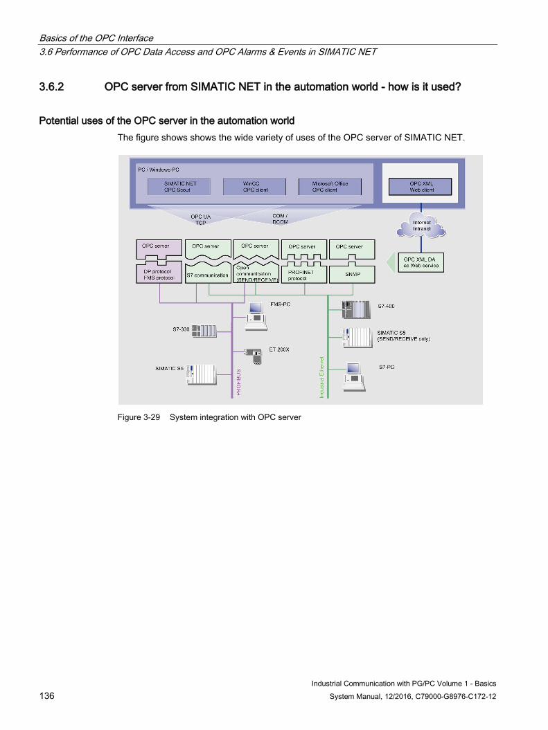
Basics of the OPC Interface 3.6 Performance of OPC Data Access and OPC Alarms & Events in SIMATIC NET
Industrial Communication with PG/PC Volume 1 - Basics 136 System Manual, 12/2016, C79000-G8976-C172-12
3.6.2 OPC server from SIMATIC NET in the automation world - how is it used?
Potential uses of the OPC server in the automation world The figure shows shows the wide variety of uses of the OPC server of SIMATIC NET.
Figure 3-29 System integration with OPC server
Basics of the OPC Interface 3.6 Performance of OPC Data Access and OPC Alarms & Events in SIMATIC NET
Industrial Communication with PG/PC Volume 1 - Basics System Manual, 12/2016, C79000-G8976-C172-12 137
3.6.3 OPC Server for SIMATIC NET - what are the advantages?
OPC server - the advantages are plain to see With the performance of OPC, SIMATIC NET provides a whole series of advantages of a general nature and for programming and development of individual clients. The personnel involved in commissioning have also not been left out.
The open OPC interface is the central interface of the products on the PG/PC from SIMATIC NET. The OPC server from SIMATIC NET supports all communications protocols and services made available by the communications modules.
The OPC server from SIMATIC NET supports the OPC Data Access interface specification for all protocols. For protocols that use mechanisms to transfer events (S7 communication and SNMP), OPC Alarms & Events is also supported.
Below, you will see how the OPC server from SIMATIC NET is used, the advantages gained from using it, and which properties are applicable. You will also see how to achieve optimum access to process data with OPC servers.
The OPC server from SIMATIC NET allows access to the industrial communication networks PROFIBUS and Industrial Ethernet from SIMATIC NET. It makes values of process variables available to OPC clients or signals events from the partner device. It does this by accessing the partner devices over the communication network using the protocol software and a communications processor from SIMATIC NET.
Advantages for Commissioning ● You use a protocol-independent interface; in other words, only one interface needs to be
installed for several applications.
● You have simple access to the communication networks of SIMATIC NET.
● With the communication network from SIMATIC NET, you can use your automation systems with numerous applications from automation engineering.
● You can integrate Microsoft Office products.
● Using DCOM, even applications installed on other computers can access the services of the OPC server over wide area or local area networks.
● The OPC Scout client application of SIMATIC NET provides you with a powerful tool for simple access to process variables.
● With the aid of SIMATIC Computing, you can create simple utilities, for example, in Visual Basic.
Basics of the OPC Interface 3.6 Performance of OPC Data Access and OPC Alarms & Events in SIMATIC NET
Industrial Communication with PG/PC Volume 1 - Basics 138 System Manual, 12/2016, C79000-G8976-C172-12
Advantages for Program Development ● You work with a vendor-independent interface. This protects your investment for the
future. You can serve a larger market and can use your developments time and time again.
● The developed applications are not dependent on the communication system of one vendor and can communicate with OPC servers of any vendor without needing to be modified.
● With the OPC interfaces, the applications have versatile access to OPC servers and the underlying communication networks.
● OPC provides high-performance interfaces for the C and C++ programming languages.
● Convenient and simple access to process data is possible in a development environment such as Visual Basic over the data control.
● You do not need to familiarize yourself with protocol- and vendor-specific interfaces.
● The option of outputting a trace simplifies troubleshooting.
● By simulating a partner device, program development is possible without installing additional devices.
What restrictions affect the OPC server? The OPC server from SIMATIC NET supports all interfaces required by the specifications for OPC Data Access and OPC Alarms & Events. It also provides the most important optional interfaces such as the browsing interface for OPC Data Access.
The optional interfaces are subject to the following restrictions:
● The OPC server for Data Access does not support "OPC public groups".
● The OPC server for Data Access does not allow timestamps and qualities to be written.
● OPC Server for Alarms & Events
– Dividing plants into areas is not possible
– Investigation of areas by browsing is not possible
The type and content of a message is not specified by the OPC specification. Using the configuration information, it is possible to specify whether alarms are signaled as simple events or conditional events.
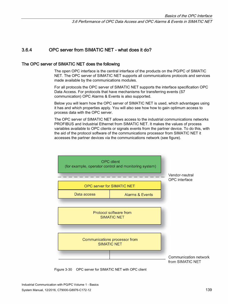
Basics of the OPC Interface 3.6 Performance of OPC Data Access and OPC Alarms & Events in SIMATIC NET
Industrial Communication with PG/PC Volume 1 - Basics System Manual, 12/2016, C79000-G8976-C172-12 139
3.6.4 OPC server from SIMATIC NET - what does it do?
The OPC server of SIMATIC NET does the following The open OPC interface is the central interface of the products on the PG/PC of SIMATIC NET. The OPC server of SIMATIC NET supports all communications protocols and services made available by the communications modules.
For all protocols the OPC server of SIMATIC NET supports the interface specification OPC Data Access. For protocols that have mechanisms for transferring events (S7 communication) OPC Alarms & Events is also supported.
Below you will learn how the OPC server of SIMATIC NET is used, which advantages using it has and which properties apply. You will also see how how to gain optimum access to process data with the OPC server.
The OPC server of SIMATIC NET allows access to the industrial communications networks PROFIBUS and Industrial Ethernet from SIMATIC NET. It makes the values of process variables available to OPC clients or signals events from the partner device. To do this, with the aid of the protocol software of the communications processor from SIMATIC NET it accesses the partner devices via the communications network (see figure).
Figure 3-30 OPC server for SIMATIC NET with OPC client
Basics of the OPC Interface 3.6 Performance of OPC Data Access and OPC Alarms & Events in SIMATIC NET
Industrial Communication with PG/PC Volume 1 - Basics 140 System Manual, 12/2016, C79000-G8976-C172-12
What special services does the OPC server provide? Since the OPC server is capable of distributing tasks to various communications systems, the OPC client can use different protocols at the same time via a single OPC server. If only 1 protocol is used in the configuration of the OPC server, no distribution is necessary. This optimizes the data throughput.
3.6.5 Process data - how is optimum access achieved?
Different Mechanisms for Accessing Process Data With the OPC Data Access, you can access different types of process data. By selecting suitable methods, you can influence the data throughput of your application.
With some protocols, you can also influence the performance of the OPC server through the choice of service and by structuring variables in the name space.
Any tips for an option data throughput? Information in the following sections:
● Using Group Operations
● Accessing the OPC Cache
● Structuring Items
● Using the Buffer Services
will help you to achieve the greatest possible data throughput
Which methods are the most suitable? There are different ways of accessing variables. Since these have different characteristics, check the advantages and disadvantages described below and select the access option most suitable for your situation.
The section
● Methods - how are suitable methods used?
will help you to make the correct decision.
Basics of the OPC Interface 3.6 Performance of OPC Data Access and OPC Alarms & Events in SIMATIC NET
Industrial Communication with PG/PC Volume 1 - Basics System Manual, 12/2016, C79000-G8976-C172-12 141
3.6.6 Group operations - how are they used?
This is how group operations are used With many methods, you can transfer several process variables in one field as parameters in one function call. The use of group operations benefits the data throughput since there are less function calls and process changeovers between the OPC client and OPC server. This allows the OPC server to optimize communication over the network itself, for example by combining individual jobs together.
If you operate with a remote server over DCOM, the use of group operations is particularly important because, in this case, a function call is transported over the network.
3.6.7 OPC cache - what is it?
This is the OPC cache The OPC cache is an internal buffer of the OPC server in which the last acquired values of the OPC items are stored.
OPC cache - how does it work? The OPC server updates all active items inserted in active groups and stores the read values in the cache. Values in the cache are only valid if the item was read successfully.
Reading a variable from the cache is far faster than access to the device. Assuming that the values in the cache are updated quickly enough for the particular application, you should therefore access the cache.
The update rate in the cache is specified by the RevisedUpdateRate parameter.
3.6.8 MaxAge - what is that?
MaxAge - what is that? With OPC Data Access 3.00, criteria for reading from the cache and sampling can be specified in greater detail.
MaxAge is the desired maximum age of a value in milliseconds until the sampling. If this age is not exceeded by a read job, the value is returned from the cache. If the time is exceeded, it must be sampled from the device again.
A MaxAge value of 0 means sampling the device (OPC_DS_DEVICE) and a MaxAge value of 1 to 0xFFFFFFFF (49.7 days) means reading from the cache (OPC_DS_CACHE).
Basics of the OPC Interface 3.6 Performance of OPC Data Access and OPC Alarms & Events in SIMATIC NET
Industrial Communication with PG/PC Volume 1 - Basics 142 System Manual, 12/2016, C79000-G8976-C172-12
3.6.9 Services use the cache - how does that work (example)?
Examples of using the cache Here, you can see examples of services that can can be used with the cache:
IOPCSyncIO::Read(...,OPC_DS_CACHE,...) The value, timestamp and quality of several OPC items are read synchronously from the cache.
IOPCAsyncIO2::Refresh(...,OPC_DS_CACHE,...) A callback is generated in the OPC client for all active OPC items regardless of the value. The value stored in the cache is sent to the client as the current value.
IOPCAsyncIO3::ReadMaxAge(...,MaxAge=500,...) A callback is generated in the OPC client for all OPC items of the group regardless of the value. The value in the cache (assuming it exists) is sent to the client as the current value if the data is not older than 500 milliseconds.
3.6.10 Protocols - which can be optimized?
Optimization is possible for the following protocols The OPC server for SIMATIC NET provides an optimization algorithm for the variable services of the following protocols:
1. S7 protocol
2. Open communication services (SEND/ RECEIVE) via Industrial Ethernet
Several simultaneous access jobs to individual variables are converted internally to a single access to the partner device. This reduces the number of data packages transported over the network, improves the utilization of the individual packages, and increases the proportion of payload data of a package.
This optimization applies both to read and write access and is activated as default. This optimization algorithm is invisible to the OPC client.
Basics of the OPC Interface 3.6 Performance of OPC Data Access and OPC Alarms & Events in SIMATIC NET
Industrial Communication with PG/PC Volume 1 - Basics System Manual, 12/2016, C79000-G8976-C172-12 143
What rules apply to the arrangement of OPC items in the name space? To allow optimization, the OPC items in the name space must be arranged according to the following rules:
● OPC items that are read or monitored simultaneously should be arranged consecutively in the name space of the partner device. Smaller gaps between the relevant parts are processed, but diminish data throughput.
● OPC items that are written simultaneously must be arranged consecutively in the name space. For optimum write access, there must be no gaps. The entire field created as a result of the optimization is transferred to the partner device. The address area of the gaps would be overwritten with undefined values. To avoid this, the OPC server once again sends individual access jobs without optimization.
3.6.11 Buffer send/receive services - why are they used?
Buffer send/receive services are used To allow transfer of large data packets, S7 communication and the open communications services (SEND/RECEIVE) via Industrial Ethernet and PROFIBUS provide buffer send/receive services. Here, data packets are sent between communications partners. The transfer of the data places load on the network only when a partner explicitly transfers a send job.
With the OPC server for SIMATIC NET, you can structure the blocks of data. This allows individual parts of the data packet to be assigned to OPC items.
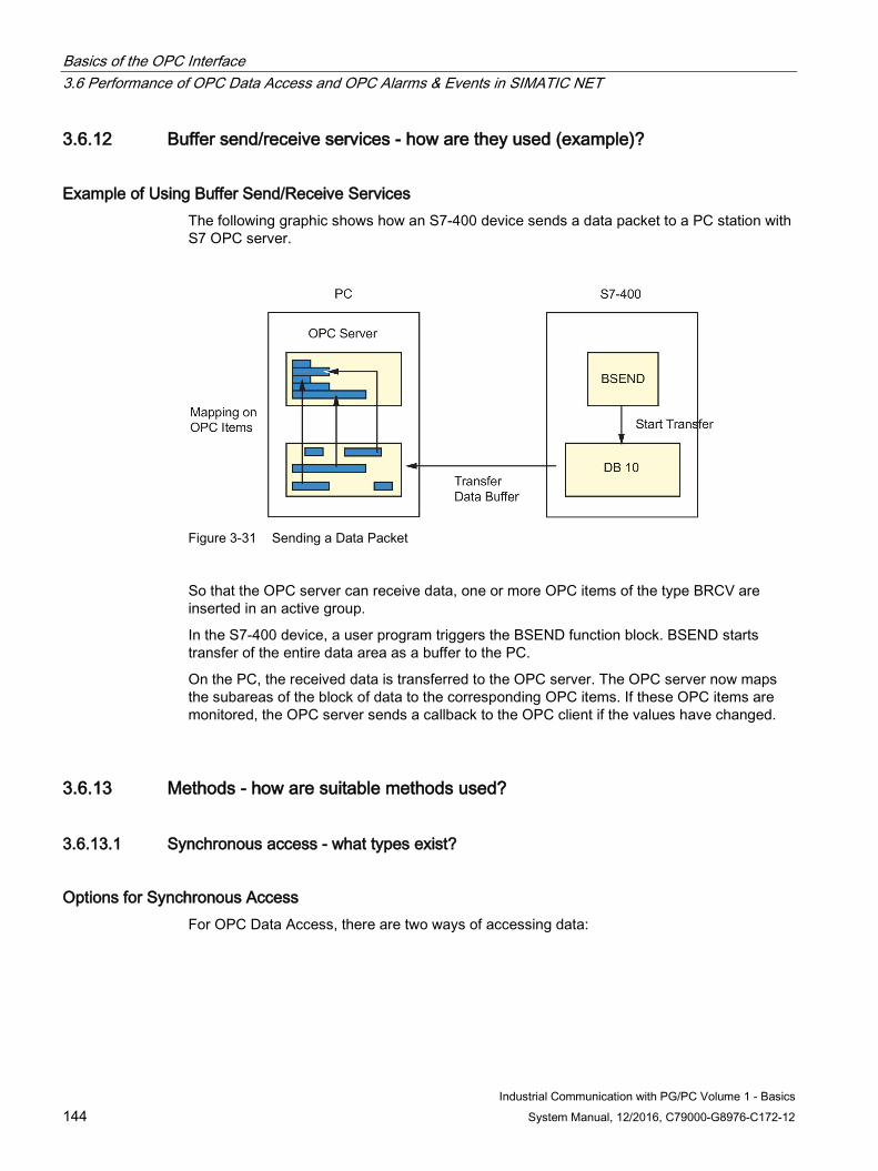
Basics of the OPC Interface 3.6 Performance of OPC Data Access and OPC Alarms & Events in SIMATIC NET
Industrial Communication with PG/PC Volume 1 - Basics 144 System Manual, 12/2016, C79000-G8976-C172-12
3.6.12 Buffer send/receive services - how are they used (example)?
Example of Using Buffer Send/Receive Services The following graphic shows how an S7-400 device sends a data packet to a PC station with S7 OPC server.
Figure 3-31 Sending a Data Packet
So that the OPC server can receive data, one or more OPC items of the type BRCV are inserted in an active group.
In the S7-400 device, a user program triggers the BSEND function block. BSEND starts transfer of the entire data area as a buffer to the PC.
On the PC, the received data is transferred to the OPC server. The OPC server now maps the subareas of the block of data to the corresponding OPC items. If these OPC items are monitored, the OPC server sends a callback to the OPC client if the values have changed.
3.6.13 Methods - how are suitable methods used?
3.6.13.1 Synchronous access - what types exist?
Options for Synchronous Access For OPC Data Access, there are two ways of accessing data:
Basics of the OPC Interface 3.6 Performance of OPC Data Access and OPC Alarms & Events in SIMATIC NET
Industrial Communication with PG/PC Volume 1 - Basics System Manual, 12/2016, C79000-G8976-C172-12 145
Synchronous Read and Write Both read and write access can be synchronous.
A program starts a synchronous function call to access process data. When the function executes, the OPC server handles the entire communication over the network. The values read are transferred to the user program with the return parameters of the function and the program can now continue the sequence with the next instructions.
Area of Application of Synchronous Access You should always use synchronous access when a longer interruption of the user program does not present a significant problem. Synchronous access is always the fast as possible access to data of the partner device.
Advantages and Disadvantages of Synchronous Access Advantages:
● Simple programming
● High data throughput since there is only one process changeover for the job between the OPC client and OPC server.
Disadvantage:
● The application is interrupted until the synchronous job has been completed. The application can only continue when all the data has been read. If the function is not called in its own thread, for example, the user interface of an interactive application is blocked during the function call.
3.6.13.2 Asynchronous access - what types exist?
Options for asynchronous access For OPC Data Access, the following options are available for accessing data:
Asynchronous reading and writing Asynchronous read or write access is possible.
A program sends an asynchronous function call to access process data. The program immediately receives feedback whether the job was successfully passed to the OPC server. Then the program continues working.
The OPC server has assigned a TransactionID to the job, via which the client can later identify the job.
At a later undefined point in time the OPC server calls the function (AsyncReadComplete) or (AsyncWriteComplete) of the OPC client. As call parameters the results of the previous function call (reading or writing) and the TransactionID are transferred to the client.
Basics of the OPC Interface 3.6 Performance of OPC Data Access and OPC Alarms & Events in SIMATIC NET
Industrial Communication with PG/PC Volume 1 - Basics 146 System Manual, 12/2016, C79000-G8976-C172-12
In terms of time the transfer of the data via the network is not dependent on the running of the program of the OPC client.
Area of application of asynchronous accessing Asynchronous access makes sense when large amounts of data need to be read and at the same time the application program should be capable of reacting while the job is being processed.
Asynchronous access to the cache of the OPC server are not useful. Only due to process transitions between the OPC client and OPC server this produces a high processor load.
Advantages and disadvantages of asynchronous access Advantages:
The application is only briefly interrupted because the actual communication runs parallel to the application.
Disadvantages:
● Creating the application is not that simple. In the application a callback mechanism needs to be implement that can accept the result of the job processing at all times. Windows programs have asynchronous mechanisms as standard, so that they can react to user input.
● When transferring few variables in a job, there is a large load caused by the process transitions when calling and calling back. It is twice as many compared with synchronous access.
3.6.13.3 Monitoring variables - what happens here?
Monitoring Variables When monitoring variables, the OPC server continuously checks whether the value or the quality of variables has changed.
To do this, the OPC client adds active OPC items to a group and activates the group. All the active OPC items in all active groups are then monitored.
The OPC client provides the OnDataChange() function. The OPC server calls this function when values have changed. As the parameters, the OPC server transfers the changed values, qualities, and time stamp of the OPC items.
The OPC client is not subjected to any load due to monitoring the variables. The program of the client executes only when a change is detected.
To prevent the OPC client from being overloaded with change messages if the process variables change quickly, you can specify the minimum update rate at which the program is called with the group-specific parameters RequestedUpdateRate and RevisedUpdateRate.
Analog values affected by noise would lead to fast sequences of change messages because the value changes slightly all the time. With the DefaultGroupDeadBand parameter, a percentage defines a range for all items of a group in which changes are not signaled. The
Basics of the OPC Interface 3.6 Performance of OPC Data Access and OPC Alarms & Events in SIMATIC NET
Industrial Communication with PG/PC Volume 1 - Basics System Manual, 12/2016, C79000-G8976-C172-12 147
absolute size of the range is the percentage of the difference between a configured high and low limit.
This is only possible when the value range of the variables was defined in the Symbol Editor.
When Should Variables Be Monitored? Monitoring variables is the optimum solution when a program always needs the latest data of the process or part of the process.
Advantages and Disadvantages of Monitoring Variables Advantages:
● The application is only notified when process data has changed. This reduces the CPU utilization.
● High data throughput because there are few process changeovers. Depending on the composition of the item structure, good optimization is possible.
● Monitoring of variables can be enabled and disabled item-specific or group-specific by the client.
● Windows programs have asynchronous mechanisms as standard, so that they can react to user input.
Disadvantages
● The reaction time from the change in a value in the process to transfer of new value to the client is higher than the update rate of the group.
● Creating the application is not that simple. The application requires an asynchronous section to receive value changes.
The update rate (RevisedUpdateRate) The "update rate" parameter that can be set via the user program (RequestedUpdateRate/RevisedUpdateRate) specifies the smallest possible time interval for checking the values of the OPC items in an active OPC group.
The server checks whether or not the value has changed. If there is a new value, the server reports new value to the client. The messages to the client are not sent faster than the "RevisedUpdateRate” set by the client. If a value changes faster than specified in the update rate, the client is not informed of interim values!
The Scan Cycle Time The scan cycle time in ms specifies how often the OPC server updates the values of the OPC items with a new communication job.
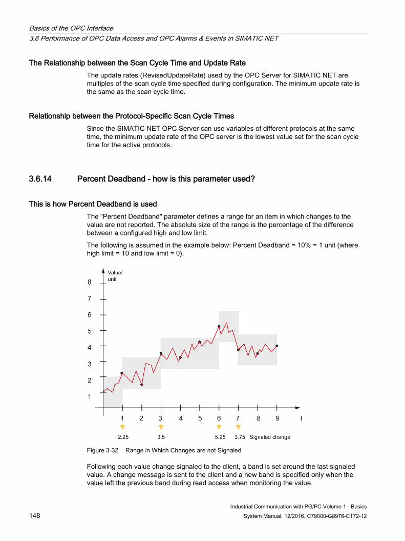
Basics of the OPC Interface 3.6 Performance of OPC Data Access and OPC Alarms & Events in SIMATIC NET
Industrial Communication with PG/PC Volume 1 - Basics 148 System Manual, 12/2016, C79000-G8976-C172-12
The Relationship between the Scan Cycle Time and Update Rate The update rates (RevisedUpdateRate) used by the OPC Server for SIMATIC NET are multiples of the scan cycle time specified during configuration. The minimum update rate is the same as the scan cycle time.
Relationship between the Protocol-Specific Scan Cycle Times Since the SIMATIC NET OPC Server can use variables of different protocols at the same time, the minimum update rate of the OPC server is the lowest value set for the scan cycle time for the active protocols.
3.6.14 Percent Deadband - how is this parameter used?
This is how Percent Deadband is used The "Percent Deadband" parameter defines a range for an item in which changes to the value are not reported. The absolute size of the range is the percentage of the difference between a configured high and low limit.
The following is assumed in the example below: Percent Deadband = 10% = 1 unit (where high limit = 10 and low limit = 0).
Figure 3-32 Range in Which Changes are not Signaled
Following each value change signaled to the client, a band is set around the last signaled value. A change message is sent to the client and a new band is specified only when the value left the previous band during read access when monitoring the value.
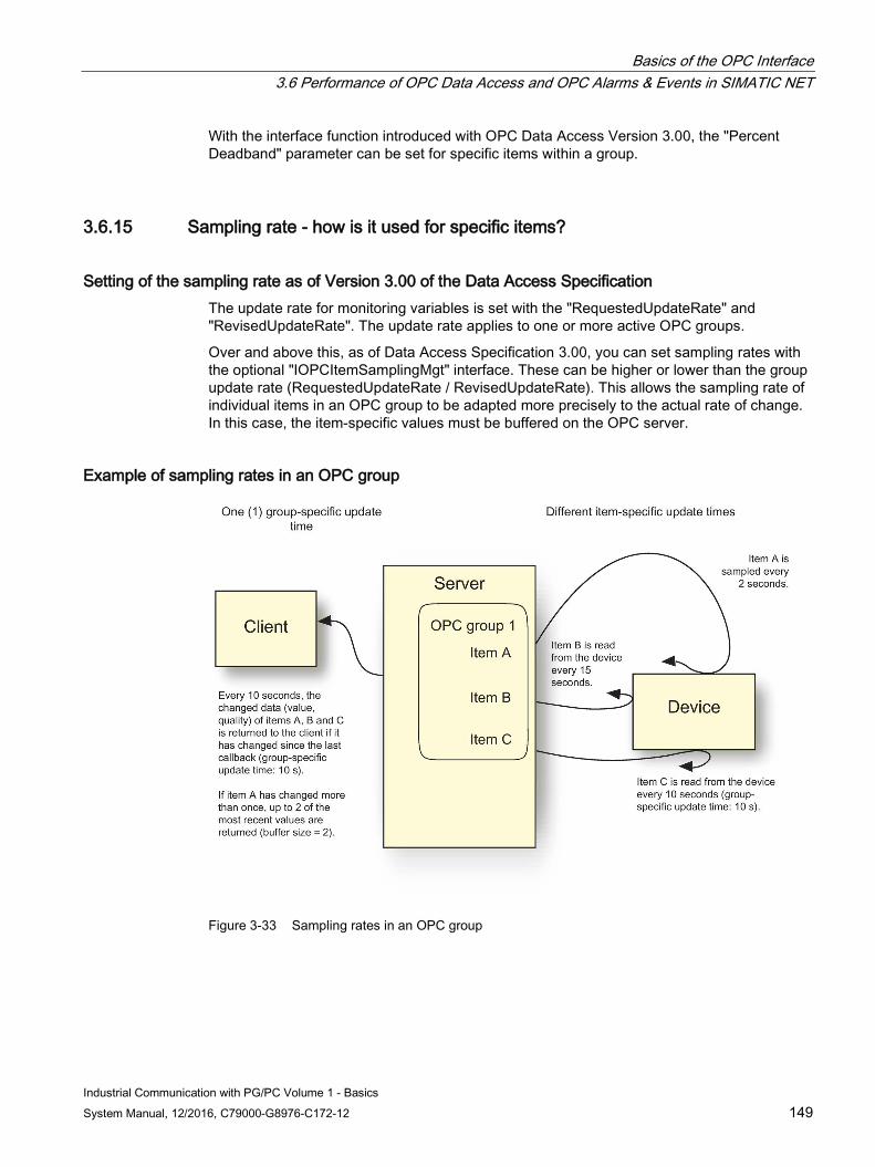
Basics of the OPC Interface 3.6 Performance of OPC Data Access and OPC Alarms & Events in SIMATIC NET
Industrial Communication with PG/PC Volume 1 - Basics System Manual, 12/2016, C79000-G8976-C172-12 149
With the interface function introduced with OPC Data Access Version 3.00, the "Percent Deadband" parameter can be set for specific items within a group.
3.6.15 Sampling rate - how is it used for specific items?
Setting of the sampling rate as of Version 3.00 of the Data Access Specification The update rate for monitoring variables is set with the "RequestedUpdateRate" and "RevisedUpdateRate". The update rate applies to one or more active OPC groups.
Over and above this, as of Data Access Specification 3.00, you can set sampling rates with the optional "IOPCItemSamplingMgt" interface. These can be higher or lower than the group update rate (RequestedUpdateRate / RevisedUpdateRate). This allows the sampling rate of individual items in an OPC group to be adapted more precisely to the actual rate of change. In this case, the item-specific values must be buffered on the OPC server.
Example of sampling rates in an OPC group
Figure 3-33 Sampling rates in an OPC group
Basics of the OPC Interface 3.6 Performance of OPC Data Access and OPC Alarms & Events in SIMATIC NET
Industrial Communication with PG/PC Volume 1 - Basics 150 System Manual, 12/2016, C79000-G8976-C172-12
OPC group 1 on the server has three items A, B and C. The group update rate is 10 seconds. The group and all items are active. The items are configured as follows:
● Item A
– Sampling rate: 2 s
– Buffering: Active
– Buffer size: 2
● Item B
– Sampling rate: 15 s
● Item C
– No configured sampling rate
With the group update rate of 10 seconds, the changed values (value, quality) of items A, B and C are transferred with timestamp to the OPC client using the callback function.
If there is more changed data from item A within the group update rate (10 s), up to 2 of the latest changed values will be transferred to the OPC client (buffer size = 2).
The group update rate to the OPC client is not changed by samples. If the desired sampling rate of the item and update rate of the group is the same, there is no difference compared with the reaction in specification version 2.xx.
Buffering and transferring the items The following rules currently apply to the return of items with a group update:
1. If the quality has changed since the last update, the item is returned to the client.
2. If the value has changed since the last update and the total change exceeds the deadband (if applicable), the item is returned to the client.
If the sampling rate is shorter than the group update rate, the server requires extra logic to decide what is returned to the client in the next update.
If buffering is not enabled and at least one sample meets criteria 1 and 2 above, the latest value will be returned to the client.
The latest sample is also returned when the last value does not meet criteria 1 and 2.
If buffering is enabled, the server does not start buffering samples until it reads a variable that meets criteria 1 and 2. Once a server starts buffering samples for an item, it will add a new sample to the buffer if the new sample has a different quality or a different value compared with the previous sample.
If the new sample is the same as the last sample in the buffer, the server only updates the timestamp of the last sample in the buffer.
To recap: The set of samples returned to the client will be a sequence of values that all differ from the previous sample and have a timestamp that reflects the last time the item was known to have that value.
If an item has more than one value/quality/timestamp to be returned with a particular OnDataChange callback, there will be multiple ClientHandles, depending on the size of the collection, returned with the corresponding value/qualitytimestamp trio.

Basics of the OPC Interface 3.6 Performance of OPC Data Access and OPC Alarms & Events in SIMATIC NET
Industrial Communication with PG/PC Volume 1 - Basics System Manual, 12/2016, C79000-G8976-C172-12 151
The function for the item buffering introduced with OPC Data Access 3.00 is called "SetItemBufferEnable".
The signaling of the values by the OPC server to the client uses the OnDataChange() function.

Industrial Communication with PG/PC Volume 1 - Basics System Manual, 12/2016, C79000-G8976-C172-12 153
References 4
Finding the SIMATIC NET documentation ● Catalogs
You will find the order numbers for the Siemens products of relevance here in the following catalogs:
– SIMATIC NET Industrial Communication / Industrial Identification, catalog IK PI
– SIMATIC Products for Totally Integrated Automation and Micro Automation, catalog ST 70
You can request the catalogs and additional information from your Siemens representative.
You can go to the Industry Mall on the Internet at the following address:
Industry Mall (https://eb.automation.siemens.com/goos/WelcomePage.aspx?regionUrl=/&nodeID=1000000&view=intranet&infoTypeID=*&language=en#topAnch)
● Documentation on the Internet
You will find SIMATIC NET manuals on the Internet pages of Siemens Automation Customer Support:
Link to Customer Support (http://support.automation.siemens.com/WW/view/en)
Go to the required product group and make the following settings:
"Entry list" tab, Entry type "Manuals / Operating Instructions"
● Documentation from the STEP 7 installation
Manuals that are included in the online documentation of the STEP 7 installation on your PG/PC can be found in the start menu ("Start" > "All Programs" > "Siemens Automation" > "Documentation").
See also Link to the documentation: (http://www.automation.siemens.com/simatic/portal/html_00/techdoku.htm)
Professional ASP.NET Web Services
WROX Press Ltd
ISBN 1-861005-45-8
Here, in particular Chapter 9 "Asynchronous Programming"
References
Industrial Communication with PG/PC Volume 1 - Basics 154 System Manual, 12/2016, C79000-G8976-C172-12
SIMATIC NET Commissioning PC Stations - instructions and getting started Configuration manual Siemens AG (SIMATIC NET Manual Collection) On the Internet under following entry ID: https://support.industry.siemens.com/cs/ww/de/view/77377601
SIMATIC NET PROFIBUS Network Manual Siemens AG
(SIMATIC NET Manual Collection)
On the Internet under the following entry ID: https://support.industry.siemens.com/cs/ww/en/view/35222591
SIMATIC NET Twisted-Pair and Fiber-Optic Networks Manual Siemens AG (SIMATIC NET Manual Collection)
Industrial Communication with PG/PC Volume 1 - Basics System Manual, 12/2016, C79000-G8976-C172-12 155
Index
A Alarm, 106, 107 Alarms & Events, 100 Areas, 104 Asynchronous access, 145
Asynchronous reading and writing, 145 Attribute, 126 Authentication, 117 Automation interface, 93
B Browse, 115 Buffer send/receive services, 30, 143, 144
C Cache, 142 Cell level, 12 Certificate, 124 Certificates, 117 Channel
secure, 124 Class model
OPC Alarms & Events, 101 OPC Data Access, 96 OPC event area browser class, 104 OPC Event Server, 102 OPC Event Subscription Class, 103 OPC group class, 97 OPC item class, 98 OPC Server Class, 97
Client-server model, 47, 67, 86 COM, 90 COM inproc server, 134 COM interfaces, 92 COM object, 90 COM objects, 91 Custom interface, 93
D Data access clients, 95 Data access server, 95
DCOM, 90 Discovery, 121 DP class 1 master, 34, 37 DP class 2 master, 34, 39 DP Slave, 43 DPC1, 34 DPC1 Services, 40 DPC2, 34 DPC2 Services, 42 DPV1, 33
E Endpoints of the OPC UA server, 121 Event Messages, 101
Condition-related events, 101 Simple events, 101 Tracking events, 101
Events, 100
F Field level, 12 Filter, 128
G GetProperties, 115 GetStatus, 114 Glossary, 10
H HTTP protocol, 111
I Industrial Ethernet, 19 InProcess Server, Instances, 121 Interface specifications, 99 Internet, 110 IO controller, 72 IO device, 72 IO supervisor, 72 IP, 24
Index
Industrial Communication with PG/PC Volume 1 - Basics 156 System Manual, 12/2016, C79000-G8976-C172-12
ISO transport protocol, 29 ISO/OSI reference model
General, 14 Industrial Ethernet, 21 PROFIBUS, 18 PROFINET, 25
Isochronous Real Time, 24, 75 ISO-on-TCP, 29
L Local Server, 87
M Management Information Base, 67 Management level, 12 Master-slave principle, 17 Monitored item, 126 Monitoring mode, 128
N NodeID, 126, 126 Nodes, 126 Notification, 126 NotificationMessage, 128
O OPC cache, 141 OPC client, 88 OPC Data Access, 95, 95 OPC Data Control, 85 OPC event area browser, 101 OPC event server, 101 OPC event subscription, 101 OPC interface, 86 OPC Scout, 85 OPC Server, 87 OPC XML, 110 Optimization, 142
P Percent Deadband, 148 Performance, 134 Polling, 36 PROFIBUS, 16 PROFINET, 23
PROFINET devices, 70 PROFINET IO, 70 ProgID, 87 Protocols
DP Protocol, 33 Open SEND/RECEIVE protocol, 27 Overview Industrial Ethernet, 13 Overview PROFIBUS, 13 RPC protocol, 74 S7 Protocol, 45 SNMP Protocol, 66
Provider-Consumer Model, 72 Publish request, 129 Publish Request, 126 Publishing interval, 129
Q Queue attributes, 128
R Read, 114 Real Time, 24 Receiving messages, 105 Remote Server, 87 RFC1006, 29
S S7 Block Management Services, 49 S7 Buffer Send/Receive Services, 48 S7 connections
Fault-tolerant, 52 S7 event service, 51 S7 Information Services, 48 S7 security service, 51 S7 Variable Services, 48 Sampling interval, 128 Session, 124 Session ID, 124 SIMATIC NET, 11 SIMATIC NET glossary, 10 SNMP agent, 67 SNMP manager, 67 SOAP, 110 Subscription, 115, 126 Support, 9 Switched Ethernet, 21 Symbols, 85
Index
Industrial Communication with PG/PC Volume 1 - Basics System Manual, 12/2016, C79000-G8976-C172-12 157
Synchronous Access, 144 Synchronous Read and Write, 145
System configuration DP protocol, 35 PROFINET IO, 71 S7 protocol, 45 SEND/RECEIVE protocol, 27 SNMP Protocol, 67
T TCP, 24 TCP/IP native protocol, 29 The token passing method, 17 Totally Integrated Automation, 11, 23 Training, 9 Types, 121
U UDP, 24 Update Rate, 147 UpdateRate, 147
V Variable services, 30
W Web Services, 112 Write, 114
X XML, 110 XML interface, 112 XML Web service, 114

Index
Industrial Communication with PG/PC Volume 1 - Basics 158 System Manual, 12/2016, C79000-G8976-C172-12