Embed Size (px)
Citation preview

CONTENTS
1 DESCRIPTION OF THE BOILER . . . . . . . . . . . . . . . . . . . . . . . . . . . . . . . . . . . . . . . . . . . . . . . . . . . . . . . . . . . . . . . . . . . . . . . . pag. 73
2 INSTALLATION . . . . . . . . . . . . . . . . . . . . . . . . . . . . . . . . . . . . . . . . . . . . . . . . . . . . . . . . . . . . . . . . . . . . . . . . . . . . . . . . . . . . . . . pag. 76
3 CHARACTERISTICS . . . . . . . . . . . . . . . . . . . . . . . . . . . . . . . . . . . . . . . . . . . . . . . . . . . . . . . . . . . . . . . . . . . . . . . . . . . . . . . . . . . pag. 84
4 USE AND MAINTENANCE . . . . . . . . . . . . . . . . . . . . . . . . . . . . . . . . . . . . . . . . . . . . . . . . . . . . . . . . . . . . . . . . . . . . . . . . . . . . pag. 88
INSTALLER INSTRUCTIONS
IMPORTANT
When carrying out commissioning of the boiler, you are highly recommended to perform the following checks:
– Make sure that there are no liquids or inflammable materials in the immediate vicinity of the boiler.
– Make sure that the electrical connections have been made correctly and that the earth wire is connected to a
good earthing system.
– Open the gas tap and check the soundness of the connections, including that of the burner.
– Make sure that the boiler is set for operation for the type of gas supplied.
– Check that the flue pipe for the outlet of the products of the combustion is unobstructed and has been pro-
perly installed.
– Make sure that any shutoff valves are open.
– Make sure that the system is charged with water and is thoroughly vented.
– Check that the circulating pump is not locked (CAUTION: Remember to release the pump coupled with the control
panel, if necessary, to protect the electronic control card).
– Purge the system, bleeding off the air present in the gas pipe by operating the pressure relief valve on the gas
valve inlet.
FOR
MA
T - E
NG
LIS
H
FONDERIE SIME S.p.A. of Via Garbo 27 - Legnago (VR) - Italy declares that its hot water boilers, which bear the CE mark underGas Directive 90/396/CEE and are fitted with a safety thermostat calibrated to a maximum of 110°C, are not subject to appli-cation of PED Directive 97/23/CEE as they meet the requirements of article 1 paragraph 3.6 of the Directive.

1.1 INTRODUCTION
“FORMAT” boilers are gas-fired thermalappliances for central heating and domestichot water production, designed and manu-factured to satisfy the needs of multipledwelling and modern plant requirements.They comply with the european directives90/396/CEE, 89/336/CEE, 73/23/CEE,
92/42/CEE and with the european specifi-cations EN 297 - EN 483. These appliances can be fired by naturalgas (methane) and butane gas (G30) orpropane gas (G31). This booklet provides the instructions forthe following boiler models:– “FORMAT 25 OF - 30 OF”
with electronic ignition and modulation,
natural draught.
– “FORMAT 25 BF - 30 BF”with electronic ignition and modulation,room sealed forced-draught.
The instructions given in this manual areprovided to ensure proper installation andperfect operation of the appliance
73
1 DESCRIPTION OF THE BOILER
1.2 DIMENSIONS
1.2.1 “FORMAT 25 OF - 30 OF”
1.2.2 “FORMAT 25 BF - 30 BF”
L
86
5
D 205 47,5 47,53
1
110370 = =70 70 7070
R M G E U
73
2,5
80
Fig. 1
370110
205 47,5 47,5
ø 10
0/
60
86
,58
65
L
73
2,5
= =70 70 70 70
R M G E U
31
80
Fig. 1/a
R C.H. return 3/4”M C.H. flow 3/4”G Gas connection 3/4”E D.H.W. inlet 1/2”U D.H.W. outlet 1/2”
25 30L mm 450 500D mm 130 150
R C.H. return 3/4”M C.H. flow 3/4”G Gas connection 3/4”E D.H.W. inlet 1/2”U D.H.W. outlet 1/2”
25 30L mm 450 500

74
1.3 TECHNICAL FEATURES
* The gas consumptions refer to the calorific value at standard conditions at 15°C - 1013 mbar.
** Differential measure between the pressure upstream of the gas valve and the depression in the room sealed
25 OF 30 OF 25 BF 30 BF
Heat output
Nominal kW 23.3 28.6 23.3 29.0
kcal/h 20,000 24,600 20,000 24,900
Minimum kW 9.3 11.7 9.3 11.5
kcal/h 8,000 10,100 8,000 9,900
D.H.W. heat output
Nominal kW 23.3 28.6 23.3 29.0
Heat input
Nominal kW 25.8 31.6 25.8 31.6
Minimum kW 10.8 13.5 10.8 13.5
Water content l 2.4 2.4 3.4 3.4
Adsorbed power consumption W 105 110 150 160
Electrical protection grade IP 44 44 44 44
Maximum water head bar 3 3 3 3
Maximum temperature °C 95 95 95 95
Expansion vessel
Water content l 7 10 7 10
Preloading pressure bar 1 1 1 1
CH. setting range °C 40÷80 40÷80 40÷80 40÷80
D.H.W. setting range °C 40÷60 40÷60 40÷60 40÷60
D.H.W. flow rate (EN 625) l/min 10.5 12.7 10.5 12.7
Continuous D.H.W. flow rate ∆t 30°C l/min 11.1 13.6 11.1 13.8
Minimum D.H.W. flow rate l/min 2 2 2 2
D.H.W pressure
Minimum bar 0.5 0.5 0.5 0.5
Maximum bar 7 7 7 7
Smokes temperature °C 119 120 135 150
Smokes flow gr/s 21.0 22.5 19.0 20.3
Category II2H3+ II2H3+ II2H3+ II2H3+
Type B11BS B11BS B22-C12-C32-C42-C52 C12-C32-C42-C52
Weight kg 35 41 43 49
Main burner nozzle
Quantity n° 13 15 13 15
Methane ø mm 1.30 1.30 1.30 1.30
G30 - G31 ø mm 0.75 0.77 0.75 0.76
Gas consumption *
Methane m3st/h 2.72 3.34 2.72 3.34
Butane (G30) kg/h 2.02 2.48 2.02 2.48
Propane (G31) kg/h 1.99 2.40 1.99 2.40
Burner gas pressure
Methane mbar 2÷9 2÷10.5 2÷9.6 2.3÷11.1**
Butane (G30) mbar 5÷27 5.2÷27.9 5÷27 5.5÷26.8**
Propane (G31) mbar 5÷35 6.9÷35.5 5÷35 6.9÷34.9**
Gas supply pressure
Methane mbar 20 20 20 20
Butane (G30) mbar 30 30 30 30
Propane (G31) mbar 37 37 37 37
75
1 11
8 7 9
10
24
23
2
3
4 5
22
17
20 21 19
6
12 131415
16
18
U E G M R
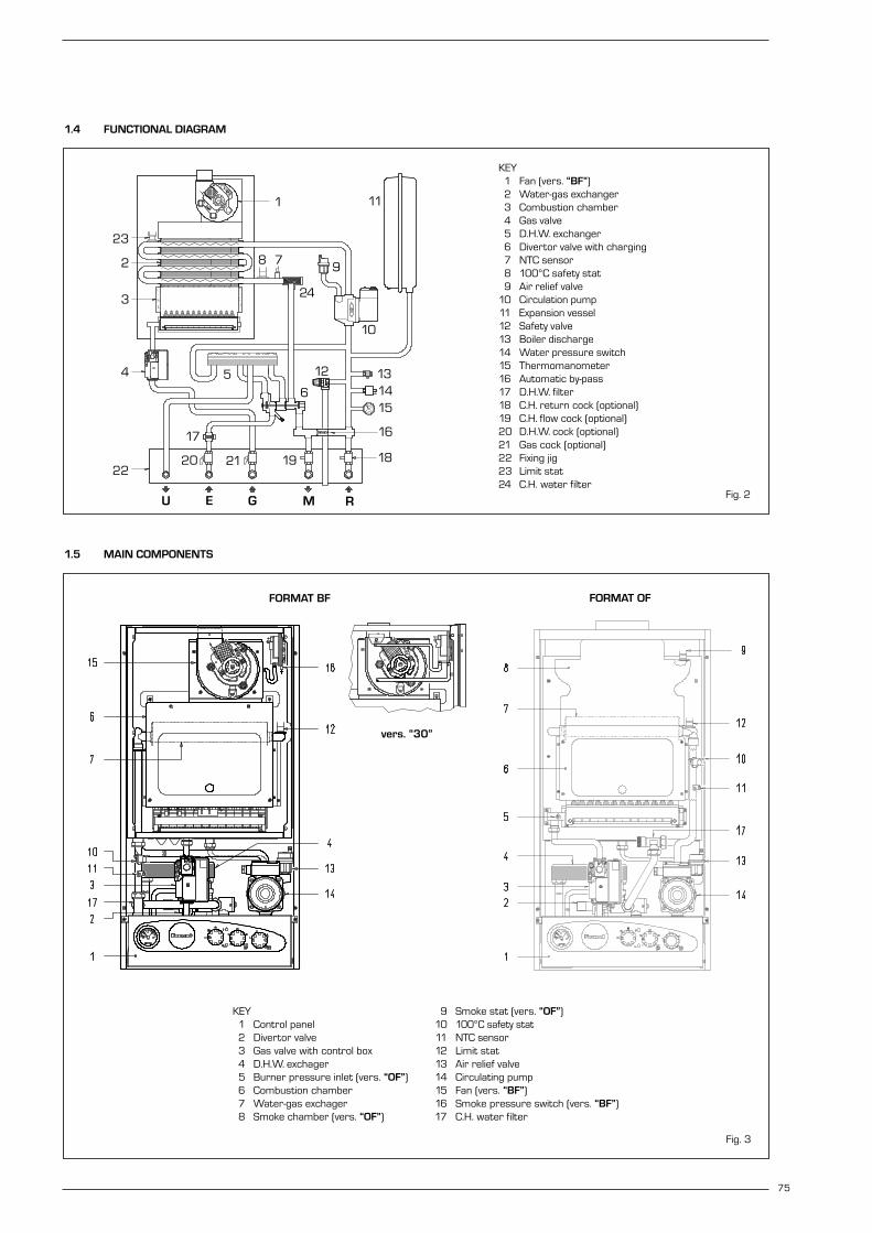
1.4 FUNCTIONAL DIAGRAM
Fig. 2
KEY1 Fan (vers. “BF”)2 Water-gas exchanger3 Combustion chamber4 Gas valve5 D.H.W. exchanger6 Divertor valve with charging7 NTC sensor8 100°C safety stat9 Air relief valve
10 Circulation pump11 Expansion vessel12 Safety valve13 Boiler discharge14 Water pressure switch15 Thermomanometer16 Automatic by-pass17 D.H.W. filter18 C.H. return cock (optional)19 C.H. flow cock (optional)20 D.H.W. cock (optional)21 Gas cock (optional)22 Fixing jig23 Limit stat24 C.H. water filter
1.5 MAIN COMPONENTS
Fig. 3
KEY1 Control panel2 Divertor valve3 Gas valve with control box4 D.H.W. exchager5 Burner pressure inlet (vers. “OF”)6 Combustion chamber7 Water-gas exchager8 Smoke chamber (vers. “OF”)
9 Smoke stat (vers. “OF”)10 100°C safety stat11 NTC sensor12 Limit stat13 Air relief valve14 Circulating pump15 Fan (vers. “BF”)16 Smoke pressure switch (vers. “BF”)17 C.H. water filter
FORMAT OFFORMAT BF
vers. “30”

The boiler must be installed in a fixed loca-tion and only by specialized and qualifiedfirms in compliance with all instructionscontained in this manual. Furthermore, the installation must be inaccordance with current standards andregulations.
2.1 VENTILATION OF BOILER ROOM
The “25 OF - 30 OF” version boilers mustbe installed in adequately ventilated dome-stic rooms. It is essential that in roomswhere the boiler are installed at least asmuch air can arrive as required by normalcombustion of the gas consumed by thevarious appliances. Consequently, it is necessary to make ope-nings in the walls for the air inlet into therooms. These openings must meet the followingrequirements:– have a total free section of at least 6
cm2 for every kW of heat input, with aminimum of 100 cm2;
– They must be located as close as possi-ble to floor level, not prone to obstruc-tion and protected by a grid which doesnot reduce the effective section requiredfor the passage of air.
The “25 BF - 30 BF” version boilers mayinstead be installed, without any con-straints regarding location or supply of airfor combustion, in any domestic rooms.
2.2 INSTALLATION PLATE
To mount the installation plate supplied asan optional extra (kit code 8075407), followthe instructions written below (fig. 4):– Fix the connecting sheet to plate (A) and
lower plate (B).– With the template complete, fix plate (A)
to the wall using the two boiler support
screws.– Check that plate (B) is perfectly horizon-
tal using a spirit level.– Connect the bends or connecting valves
supplied in the optional kit to the systempipes.
2.2.1 Fitting the pipeelbows (optional)
To fit the connecting elbows supplied in kitcode 8075418, follow the instructionsreported in fig. 5.
2.2.2 Fitting isolating valves (optional)
To fit the isolating valves, supplied in kit code8091806, follow the instructions mentio-ned in fig. 6.
2.2.3 Replacement wall kit for other makes (optional)
The kit code 8093900 is supplied comple-te with mounting instructions.
2.3 CONNECTING UP SYSTEM
Before proceeding to connect up the boiler,you are recommended to make the air cir-culating in the piping in order to eliminate
any foreign bodies that might be detrimentalto the operating efficiency of the appliance. The discharge pipe of the safety valvemust be connected to a collector funnelfor channelling away any discharge if thesafety valve goes into action. If the heating system is on a higher floorthan the boiler, install the on/off taps sup-plied in kit code 8091806 on the heatingsystem delivery/return pipes. The gas connection must be made using
seamless steel pipe (Mannesmann type),galvanized and with threaded joints provi-ded with gaskets, excluding three-piece con-nections, except for initial and end connec-tions. Where the piping has to pass throughwalls, a suitable insulating sleeve must beprovided. When sizing gas piping, from themeter to the boiler, take into account boththe volume flow rates (consumption) inm3/h and the relative density of the gas inquestion. The sections of the piping making up thesystem must be such as to guarantee asupply of gas sufficient to cover the maxi-mum demand, limiting pressure lossbetween the gas meter and any apparatusbeing used to not greater than:– 1.0 mbar for family II gases (natural gas);– 2.0 mbar for family III gases (butane or
propane).
An adhesive data plate is sticked inside thefront panel; it contains all the technical dataidentifying the boiler and the type of gas forwhich the boiler is arranged.
76
2 INSTALLATION
Fig. 4
KEY1 Fixing jig2 Elbow 1/2”x143 Gasket ø 18.5/11.54 Elbow 3/4” x 185 Gasket ø 24/176 Copper pipe 3/4”x187 Gas cock 3/4” MF8 Copper isolation valve9 Isolation valve 1/2” MF
Fig. 5
KEY1 Fixing jig2 Straight coupling 1/2”x143 Gasket ø 18.5/11.54 Elbow 1/2”x145 Copper pipe 1/2”x146 Isolation valve 1/2” MF7 Isolation valve 3/4” MF8 Gasket ø 24/179 Gas cock 3/4” MF
10 Straight coupling 3/4”x18
11 Copper pipe 3/4”x1812 Straight coupling
3/4”x18 with olive
Fig. 6

2.3.1 Filter on the gas pipe
The gas valve is supplied ex factory with aninlet filter, which, however, is not adequateto entrap all the impurities in the gas or ingas main pipes.To prevent malfunctioning of the valve, or incertain cases even to cut out the safetydevice with which the valve is equipped,install an adequate filter on the gas pipe.
2.4 CHARACTERISTICS OF FEEDWATER
To prevent lime scale and damage to thetap water exchanger, the water suppliedshould have a hardness of no more than20°F. In all cases the water used should betested and adequate treatment devicesshould be installed. To prevent lime scale ordeposits on the primary exchanger, thewater used to supply the heating circuitshould must be treated in accordance withUNI-CTI 8065 standards.It is absolutely essential that the water is tobe treated in the following cases:– very extensive system (with high con-
tents of feedwater);– frequent addition of makeup water into
the system;– should it be necessary to empty the
system either partially or totally.
2.5 SYSTEM FILLING
Filling of the boiler and the system is doneby the charge cock on the divertor valve (2fig. 7). The charge pressure, with thesystem cold, must be between 1 and 1.2bar. During system filling you are recom-mended to keep the main switch turnedOFF. Filling must be done slowly so as toallow any air bubbles to be bled off throughthe air valves. Should the pressure haverisen well above the limit expected, dischar-ge the over pressure by opening the pres-sure-relief valve (9 fig. 7).
2.6 FLUE
The flue for the atmospherical expulsion ofthe combustion products from naturaldraught appliances must meet the followingrequirements:– Be gas-tight to the combustion products,
waterproof and thermally insulated.– Be built of materials suitable for keep
resisting to normal mechanical stresses,heat, and the action of combustion pro-ducts and their possible condensates.
– Follow a vertical path and not presentany throttl ing throughout its entirelength.
– Be adequately insulated to prevent phe-nomena of condensation or smokes coo-ling, in particular if located outside thebuilding or in unheated ambiences.
– Be set at an adequate distance from
combustible or easily inflammable mate-rial by means of an air gap or suitableinsulating material.
– Have beneath the mouth of the firstsmoke duct a chamber for collectingsolid material and any condensate; theheight of the chamber must be at least500 mm. Access to the chamber must be guaran-teed by means of an opening providedwith an air-tight metal door.
– Have a circular, square, or rectangularinternal cross section; in the case ofsquare or rectangular sections, the cor-ners must be rounded off with a radiusof not less than 20 mm. However,hydraulically equivalent cross sectionsare allowed.
– Be equipped with a chimney-pot at thetop, which must be outside the so-calledback-flow zone, so as to prevent the for-mation of back-flow, which prevents freedischarge of the products of combustioninto the atmosphere.
– Be devoid of mechanical means of suc-tion located at the top of the pipe.
– No overpressure should be present in achimney that passes within or close upto inhabited rooms.
2.6.1 Connecting up flue
Fig. 8 refers to the connection of the boiler“25 OF - 30 OF” to the flue or chimneythrough smoke ducts. When making theconnection, in addition to respecting thedimensions given, you are recommendedto use gas-tight materials capable of resi-sting over time mechanical stresses andthe smokes heat.At any point along the smoke duct, the tem-perature of the combustion products mustbe higher than the dew point. More than atotal of three changes of direction must notbe made, including the inlet connection tothe chimney/flue. For any changes of direction use only cur-ved pipe lengths.
Fig. 8/a shows some applications of drau-ght terminals that ensure proper expulsionof the combustion products, in case ofdischarge through the wall.
2.7 “25 BF - 30 BF” COAXIAL DUCT
The air inlet-smoke outlet assembly ø60/100 is supplied in a kit code 8084805complete with mounting instructions.
77
1 2 3 4 8
5
7
6
9
KEY1 D.H.W. inlet-
outlet manifold2 Filling cock3 D.H.W. filter4 Manifold by-pass5 Water rate adjuster6 D.H.W. exchager7 Microswitches8 Water pressure switch9 Pressure-relief valve
Fig. 7
Fig. 8
Fig. 8/a

2.7.1 Installation of diaphragm
The diaphragm is normally suppliedtogether with boiler version “30 BF”. Seefig. 9 for positioning.
ATTENTION: Install the diaphragm onlywhen the length of the ø 60/100 coaxialpipe is less than 1 m.
2.7.2 Coaxial duct accessories
The accessories to be used for this type ofinstallation and some of the connectingsystems that may be adopted are illustra-ted in fig. 10. With the pipe bend included in the kit, themaximum length of the piping should notexceed 3 m. When the vertical extension code8086900 is used, the terminal part of thepipe must always come out horizontally.
2.7.3 Positioning the outlet terminals
The outlet terminals for forced-draughtappliances may be located in the externalperimeter walls of the building. To provide some indications of possible solu-tions, Table 1 gives the minimum distancesto be observed, with reference to the typeof building shown in fig. 10/a.
2.7.4 Coaxial duct outlet on the roof
The roof discharge terminal L. 1284 cannotbe shortened and when positioning the tile,the minimum distance from the dischargehead terminal must not be less than 600mm (fig. 11). The accessories to be used for this type ofinstallation and some of the connectingsystems that may be adopted are illustra-ted in fig. 12. It is possible to insert up to a maximum ofthree extensions and reach a maximum
78
KEY1a-b Coaxial duct kit L. 935 code 80848052 a Extension L. 1000 code 80961002 b Extension L. 500 code 8096101
3 Vertical extension L. 200 with take-off point code 8086908
4 Supplementaty 90° elbow code 8095800
TABLE 1
Siting of terminal Appliances from 7 to 35 kW(distances in mm)
A - below openable window 600B - below ventilation opening 600C - below eaves 300D - below balcony (1) 300E - from adjacent window 400F - from adjacent ventilation opening 600G - from horizontal or vertical soil or drain pipes (2) 300H - from corner of building 300I - from recess in building 300L - from ground level or other treadable surface 2500M - between two terminals set vertically 1500N - between two terminals set horizontally 1000O - from a surface facing without openings or terminals 2000P - as above but with openings and terminals 3000
Fig. 10/a
Fig. 10
1) Terminals below a practicable balcony must be located in such a way that the total pathof the smoke from its outlet point from the terminal to its outlet point from the externalperimeter of the balcony, including the height of possible railings, is not less than 2000mm.
2) When siting terminals, where materials that may be subject to the action of the combu-stion products are present in the vicinity, e.g., eaves, gutters and downspouts painted ormade of plastic material, projecting timberwork, etc., distances of not less than 1500 mmmust be adopted, unless adequate shielding is provided to guard these materials.
Fig. 9
IMPORTANT: – Each additional 90° curve installed reduces the
available length by 0.90 metres.– Each additional 45° curve installed reduces the
available length by 0.45 metres.

rectilinear distance of 3.7 m. Should it be necessary to make two chan-ges of direction in the pipe development,the maximum length of the pipe must notexceed 2 m.
2.8 “25 BF - 30 BF” SEPARATE PIPES
When installing the pipes, follow closelythe requirements of the current stan-dards, as well as the following practicalpointers:– The temperature on the surface of the
discharge pipe, in the portions that passthrough masonry and/or come intocontact with walls should not exceedroom temperature by more than 60°C(pr EN 483).
– With direct intake from outside, whenthe pipe is longer than 1 m, you arerecommended to insulate the piping soas to prevent formation of dew on theoutside of the piping during particularlyhard periods of the year.
– With the outlet pipe outside the buildingor in cold indoor environments, insulationis necessary to prevent burner failure instarting. In such cases, provide for a condensate-collector system on the piping.
The maximum overall length of the intakeand exhaust ducts depends on the headlosses of the single fittings installed(excluding the doublers) and must not begreater than 7.00 mm H2O (vers. “25”)and 11.00 mm H2O (vers. “30”).
For head losses in the fittings, refer toTable 2.
79
TABLE 2
Accessories ø 80 Head loss (mm H2O)
“25” version “30” version
Inlet Outlet Roof outlet Inlet Outlet Roof outlet
90° elbow MF 0,30 0,40 – 0,30 0,50 –45° elbow MF 0,20 0,30 – 0,20 0,40 –Extension L. 1000 (horizontal) 0,20 0,30 – 0,20 0,40 –Extension L. 1000 (vertical) 0,30 0,20 – 0,30 0,30 –Outlet terminal – 0,30 – – 0,40 –Intake terminal 0,10 – – 0,10 – –Doubler fitting 0,20 – – 0,30 – –Roof outlet terminal L.1390 – – 0,50 – – 0,60Tee condensation outlet – 0,90 – – 1,10 –
Example of allowable installation calculation (“25” version) in that the sum of the head los-ses of the single fittings is less than 7.00 mm H2O:
Intake Outlet7 meter horizontal pipe ø 80 x 0.20 1.40 –7 meter vertical pipe ø 80 x 0.30 – 2.10n° 2 90° elbows ø 80 x 0.30 0.60 –n° 2 90° elbows ø 80 x 0.40 – 0.80N° 1 terminal ø 80 0.10 0.30
Total head loss 2.10 + 3.20 = 5.3 mm H2O
With this total head loss, remove the ø 38 baffle from the intake pipe.
KEY1 Tile with articulated joint2 Lead panel3 Collar4 Locking screw
Fig. 11
Fig. 12
KEY1 Vertical extension L. 200 with take-off point code 80869082 a Extension L. 1000 code 80961002 b Extension L. 500 code 80961013 Tile with articulation joint code 80913004 Roof outlet terminal L. 1284 code 80912005 Supplementaty 90° elbow code 80958006 Supplementaty 45° elbow code 8095900

2.8.1 Separate pipe accessories
Kit code 8093000 is supplied for this pur-pose (fig. 13). The sectored diaphragm is to be usedaccording to the maximum head lossallowed in both pipes, as given in fig. 14. The complete range of accessories neces-sary for satisfying all installation require-
ments is reported in fig. 15.
2.8.2 Separate-pipes roof outlet
The roof outlet terminal L. 1390 cannot beshortened and when positioning the tile, theminimum distance from the discharge headterminal must not be less than 700 mm(fig. 16).The accessories to be used for this type ofinstallation and some of the connectingsystems that may be adopted are illustra-ted in fig. 17.There is the possibility of doubling the air-intake and smoke-outlet pipes and then brin-
ging them back together again so as toobtain a concentric discharge by using thedoubler fitting (7 fig. 17). In these cases, when assembling, recoverthe silicone gasket used on the terminaladapter (5 fig. 16), which is to be replacedby the doubler, and insert it into the seatmade in the doubler.
For this type of discharge the sum of themaximum rectilinear development allowedfor the pipes must not exceed 7.00 mmH2O (“25” vers.) and 11.00 mm H2O (“30”vers.). When calculating the lengths of pipe,take into account the parameters given inthe Table 2.
80
Fig. 13
120= =
ø 8
0
160
KEY1 Sponge-rubber gasket ø125/952 Fixing screw3 Air-smokes flow splitting unit
with take-off point4 Sectors of diaphragm ø 38
Fig. 14
Fig. 15
KEY1 Air-smokes flow plitting unit
with take-off point code 80930002a 90° elbow MF (n° 6) code 80774102b Isolated 90° elbow MF code 80774083a Extension L. 1000 (n° 6) code 80960033b Isolated extension L. 1000 code 80773063c Extension L. 500 (n° 6) code 80960024 Outlet terminal code 80895015 Int.-est. ring kit code 80915006 Intake terminal code 80895007 45° elbow MF (n° 6) code 80774118 Condensation outlet L. 135 code 80928009 Locking junction (n° 5) code 8092700
SECTOR OF DIAPHRAGM
Sectors of diaphragm Total head loss to remove mm H2O Pa
1 0 ÷ 2 0 ÷ 19,62 2 ÷ 3 19,6 ÷ 29,44 3 ÷ 4 29,4 ÷ 39,26 4 ÷ 5 39,2 ÷ 49,0
Remove diaphragm 5 ÷ 7 49,0 ÷ 68,6
“25 BF” version
Sectors of diaphragm Total head loss to remove mm H2O Pa
1 0 ÷ 1 0 ÷ 9,82 1 ÷ 2 9,8 ÷ 19,63 2 ÷ 4 19,6 ÷ 39,24 4 ÷ 5 39,2 ÷ 49,05 5 ÷ 6 49,0 ÷ 58,86 6 ÷ 7 58,8 ÷ 68,6
Remove diaphragm 7 ÷ 8 68,6 ÷ 78,4
“25 BF” version B22 type
Sectors of diaphragm Total head loss to remove mm H2O Pa
1 0 ÷ 2 0 ÷ 19,62 2 ÷ 3 19,6 ÷ 29,43 3 ÷ 4 29,4 ÷ 39,24 4 ÷ 5 39,2 ÷ 49,05 5 ÷ 6 49,0 ÷ 58,86 6 ÷ 7 58,8 ÷ 68,6
Remove diaphragm 7 ÷ 11 68,6 ÷ 107,8
“30 BF” version

2.9 FORCED OUTLET
The “25 BF” version can also be installed asa B22 type apparatus by assembling thestub pipe inlet/outlet kit cod. 8089950.The kit comes with a sector diaphgram,instruction sheet and a label with the roomaeration warnings to be attached to the boi-ler casing. The sector diaphram must beused according to the maximum load lossallowed by the duct, as indicated in fig. 14.The complete range of fittings required tocarry out the installation is given in fig. 18.The maximum length of the duct is deter-mined by the load losses of the single atta-ched fittings (excluding the inlet/outletstub pipe) and should not be greater than8.00 mm H2O.To calculate the load loss of the individual fit-tings attached see Table 2.
2.10 ELECTRICAL CONNECTION
The boiler is supplied with an electric cable.Should this require replacement, it must bepurchased exclusively from SIME. The electric power supply to the boiler mustbe 230V~50Hz single-phase through afused main switch, with at least 3 mm spa-cing between contacts.
NOTE: Device must be connected to anefficient earthing system. SIME declinesall responsibility for injury or damage topersons, animals or things, resulting fromthe failure to provide for proper earthingof the appliance.
2.10.1 Electric switchboard
To access the electrical panel, turn off thepower supply, remove the front casing paneland the two screws holding the controlpanel to the sides (see point 4.7).
The panel will tilt forward at a sufficient angleto allow access to the components. To remove the protection, unscrew the fixingscrews and use a screwdriver to release theupper tabs and free it from the control panel(fig. 19).
81
Fig. 17
KEY1 Air-smokes flow splitting unit
with take-off point code 80930002 a 90° elbow MF (n° 6)
code 80774102 b Isolated 90° elbows MF
code 80774083 a Extension L. 1000 (n° 6)
code 80960033 b Isolated extension L. 1000
code 80773063 c Extension L. 500 (n° 6)
code 80960024 Int.-est. ring kit code 80915005 Intake terminal code 80895006 Locking junction (n° 5)
code 80927007 Doubler fitting code 80914008 Tile with articulated joint
code 80913009 Roof outlet terminal L. 1390
code 809120110 45° elbow MF (n° 6)
code 807741111 Condensation outlet L. 135
code 809280012 Tee condensation outlet
code 8093300
Fig. 16
Fig. 18
KEY1 Inlet/outlet terminal2 Sectors diaphragm3 90° elbow MF with point
cod. 80774074a Extension L. 1000 (n° 6)
cod. 80960034b Isolated extension L. 1000
cod. 80773064c Extension L. 500 (n° 6)
cod. 80960025 Locking junction (n° 5)
cod. 8092700
6 90° elbow MF (n° 6) cod. 80774107 Extension L. 135 with point
cod. 80773048 45° elbow MF (n° 6) cod. 80774119 Condensation outlet L. 135
cod. 809280010 Tile with articulated joint
cod. 809130011 Roof outlet terminal L. 1390
cod. 809120112 Tee condensation outlet
cod. 8093300
KEY1 Tile with articulated joint2 Lead panel3 Collar4 Locking screw5 Reducing fitting
with gasket

2.10.2 Room stat connection
To gain access to connector TA, removethe control panel cover (7 fig. 9) and con-
nect the room stat to the terminals 22-23after having removed the jumper.
The thermostat or timer-thermostat,
recommended for better room tempe-rature control, must be class II as spe-cified by standard EN 60730.1 (cleancontact).
82
2.10.3 “25 OF - 30 OF” wiring diagram with SIT control box
Fig. 20
KEYEV1 Gas valve coilEV2 Gas valve coilEA Ignition electrodeER Sensing electrodeA SIT 503 control boxTS 100°C safety statTF Smoke statPA Water pressure switchP Circulation pumpVP Divertor valveTAG Antifreeze stat (optional)C Rotary switch TA Room statM ModulatorSM C.H. sensorTL Limit stat
Note: The room stat (TA) must be connected to the terminals 22-23
1 2
6 7
5 8
3 4
KEY1 Thermomanometer2 Timer-programmer housing 3 Rotary switch4 Electronic board5 Earth faston6 Instrument protection7 Room stat cover8 Room stat connector
Fig. 19
CONNECTOR SPAREPART CODES:
J1 code 6260966J2 code 6260962J3 code 6260968J5 code 6260957

83
2.10.4 “25 BF - 30 BF” wiring diagram with SIT control box
Fig. 20/a
KEYEV1 Gas valve coilEV2 Gas valve coilEA Ignition electrodeER Sensing electrodeA SIT 503 control boxTS 100°C safety statPF Smoke pressure switchV FanPA Water pressure switchP Circulation pumpVP Diverto valveTAG Antifreeze stat (optional)C Rotary switch TA Room statM ModulatorSM C.H. sensorTL Limit stat
Note: The room stat (TA) must be connected to the terminals 22-23
2.10.5 “25 OF - 30 OF” wiring diagram with HONEYWELL control box
Fig. 20/b
KEYEV1 Gas valve coilEV2 Gas valve coilEA Ignition electrodeER Sensing electrodeA HONEYWELL S4565CF
control boxTS 100°C safety statTF Smoke statPA Water pressure switchP Circulation pumpVP Divertor valveTAG Antifreeze stat (optional)C Rotary switch TA Room statM ModulatorSM C.H. sensorTL Limit statNote: The room stat (TA) must be connected to the terminals 22-23
CONNECTOR SPAREPART CODES:
J1 code 6260956J2 code 6260961J3 code 6260968J5 code 6260964
CONNECTOR SPARE PART CODES:
J1 code 6260966J2 code 6260960J3 code 6260968J5 code 6260957

3.1 ELECTRONIC BOARD
The electronic boards are manufactured incompliance with the EEC 73/23 low-voltagedirectives. They are supplied with 230V and,through a built-in transformer, send a volta-ge of 24V to the following components:modulator, C.H. sensor and time program-mer. An automatic and continuous modula-tion system enables the boiler to adjust theheat output to the various system require-ments or the User’s needs. The electroniccomponents are guaranteed against a tem-perature range of –10 to +60°C.
3.1.1 Central heating operation
Upon demand for heating from the roomtemperature stat, the circulation pump isactivated, and approximately 90 secondsmust elapse for the burner to start opera-ting. This will happen only if the temperatureis set above the value detected by the hea-ting sensor. The setting range is between40 and 80°C. The heat output can be variedaccording to the system needs by adjusting
the trimmer (1 fig. 21). At start-up of eachworking cycle, after the period of slow igni-tion having a duration of approx. 5 sec, theboiler will set itself at the heat output set onthe “Minimum heating pressure” trimmer.
3.1.2 D.H.W. operation
Upon demand for hot water, the boilerstarts instantaneously when the microswit-ch on the pressure switch valve trips. Therequired power output is regulated, viaflame modulation, by the hot water sensor,which will compare the temperature readwith the temperature set on the potentio-meter. The adjustment range is between 40and 60°C. When the heating flow sensor isat 75°C the electronic limiter will trip andswitch-off the burner. The burner will re-igni-te when the temperature falls below 2 °C.
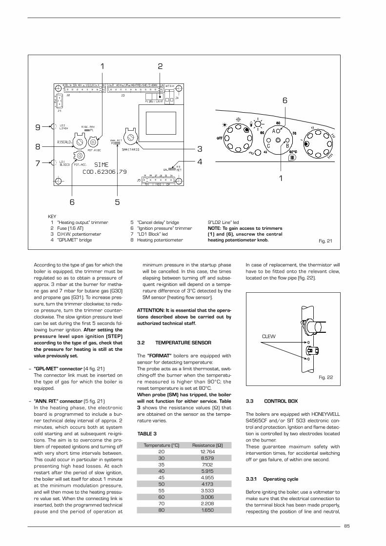
3.1.3 Control leds
The electronic board is equipped with controlleds which show some of the possible failures
that can cause an irregular and/or improperoperation of the appliance. The leds are loca-ted on the card as indicated in fig. 21 andmarked with the following wording: – “LD1 BLOCCO”
Red led on when control box, safety statand/or smoke stat trips.
– “LD2 LINEA”Green led off when there is no tensionpresent.
3.1.4 Devices available on the electronic board
The electronic board is equipped with thefollowing devices:
– “POT. RISC.” trimmer (1 fig. 21)Sets the maximum heating power value.To increase the value turn the trimmerclockwise; to reduce the value turn thetrimmer anticlockwise.
– “POT. ACC.” trimmer (6 fig. 21)Trimmer to vary the pressure level uponignition (STEP), of the gas valve.
84
3 CHARACTERISTICS
2.10.6 “25 BF - 30 BF” wiring diagram with HONEYWELL control box
Fig. 20/c
KEYEV1 Gas valve coilEV2 Gas valve coilEA Ignition electrodeER Sensing electrodeA HONEYWELL S4565CF
control boxTS 100°C safety statPF Smoke pressure switchV FanPA Water pressure switchP Circulation pumpVP Divertor valveTAG Antifreeze stat (optional)C Rotary switchTA Room statM ModulatorSM S.H. sensorTL Limit statNote: The room stat (TA) must be connected to the terminals 22-23
CONNECTOR SPARE PART CODES:
J1 code 6260956J2 code 6260959J3 code 6260968J5 code 6260964
85
According to the type of gas for which theboiler is equipped, the trimmer must beregulated so as to obtain a pressure ofapprox. 3 mbar at the burner for metha-ne gas and 7 mbar for butane gas (G30)and propane gas (G31). To increase pres-sure, turn the trimmer clockwise; to redu-ce pressure, turn the trimmer counter-clockwise. The slow ignition pressure levelcan be set during the first 5 seconds fol-lowing burner ignition. After setting thepressure level upon ignition (STEP)according to the type of gas, check thatthe pressure for heating is still at thevalue previously set.
– “GPL-MET” connector (4 fig. 21)The connector link must be inserted onthe type of gas for which the boiler isequipped.
– “ANN. RIT.” connector (5 fig. 21)In the heating phase, the electronicboard is programmed to include a bur-ner technical delay interval of approx. 2minutes, which occurs both at systemcold starting and at subsequent re-igni-tions. The aim is to overcome the pro-blem of repeated ignitions and turning offwith very short time intervals between.This could occur in particular in systemspresenting high head losses. At eachrestart after the period of slow ignition,the boiler will set itself for about 1 minuteat the minimum modulation pressure,and will then move to the heating pressu-re value set. When the connecting link isinserted, both the programmed technicalpause and the period of operation at
minimum pressure in the startup phasewill be cancelled. In this case, the timeselapsing between turning off and subse-quent re-ignition will depend on a tempe-rature difference of 3°C detected by theSM sensor (heating flow sensor).
ATTENTION: It is essential that the opera-tions described above be carried out byauthorized technical staff.
3.2 TEMPERATURE SENSOR
The “FORMAT” boilers are equipped withsensor for detecting temperature:The probe acts as a limit thermostat, swit-ching-off the burner when the temperatu-re measured is higher than 90°C; thereset temperature is set at 80°C. When probe (SM) has tripped, the boilerwill not function for either service. Table3 shows the resistance values (Ω) thatare obtained on the sensor as the tempe-rature varies.
In case of replacement, the thermistor willhave to be fitted onto the relevant clew,located on the flow pipe (fig. 22).
3.3 CONTROL BOX
The boilers are equipped with HONEYWELLS4565CF and/or SIT 503 electronic con-trol and protection. Ignition and flame detec-tion is controlled by two electrodes locatedon the burner. These guarantee maximum safety withintervention times, for accidental switchingoff or gas failure, of within one second.
3.3.1 Operating cycle
Before igniting the boiler, use a voltmeter tomake sure that the electrical connection tothe terminal block has been made properly,respecting the position of line and neutral,
TABLE 3
Temperature (°C) Resistance (Ω)20 12.76430 8.57935 7.10240 5.91545 4.95550 4.17355 3.53360 3.00670 2.20880 1.650
Fig. 22
CLEW
Fig. 21
KEY1 “Heating output” trimmer2 Fuse (1.6 AT)3 D.H.W. potentiometer4 “GPL-MET” bridge
5 “Cancel delay” bridge6 “Ignition pressure” trimmer7 “LD1 Block” led8 Heating potentiometer
9“LD2 Line” ledNOTE: To gain access to trimmers(1) and (6), unscrew the centralheating potentiometer knob.
21
5
9
8
7
3
6
4
6
1
C

as shown in the diagram. Rotate the selector to summer or winter,the red led should light up. The boiler is now ready to start workingupon demand for heating or drawing off ofD.H.W.; a discharge current is sent to theignition electrode through the programmer,and the gas valve opens at the same time.Burner ignition normally takes place within2 or 3 seconds. However, it is possible for ignition failuresto occur, with consequent activation ofsignal indicating that the control box has“locked out”.
– Gas failureThe control box runs through the cyclenormally sending electric power to theignition electrode. The electrode continues spark dischargefor a maximum of 10 sec. If the burner does not ignite, the controlbox “locks out”.
This may occur upon first ignition orafter long periods of boiler lay-off whenthere is air in the pipes. It may be caused by the gas cock beingclosed or by one of the valve coils havinga break in the winding, so that the valvecannot open. The HONEYWELL valveconnector is defective.
– Ignition electrode fails to sparkIn the boiler, only the gas to the burner isseen to open. After 10 sec. the controlbox “locks out”.
This may be due to a break in the wire ofthe electrode or to the wire not properlyfastened to the electric terminal of thecontrol box; or else, the transformer hasburnt out.
– No detection of flameThe continuous spark discharge of theelectrode is noted starting from ignitioneven though the burner is lit. Af ter 10 seconds have elapsed, thesparks cease, the burner goes out, andthe warning light indicating equipment“lock-out” lights up.
This occurs when the position of phaseand neutral has not been respected onthe terminal block.There could have a break in the wire ofthe sensing electrode or the electrodeitself is touching earth: the electrode isworn out and needs replacing. The con-trol box is defective.
When there is a sudden voltage failure, theburner shuts out immediately; when powersupply returns, the boiler will start up againautomatically.
3.3.2 Operating cycle
At each start-up the programmers perform
a self-check which, if there is a malfunctionor parasite flame signal, disables the pro-gram start. The programmer will not start when the airpressure switch is not in the non-ventingposition.
3.4 “25 OF - 30 OF” SMOKE SAFETY DEVICE
This is a safety device against possiblesmoke emission into the ambience (9 fig. 3).The safety device goes into action byblocking operation of the gas valve when thereturn of the smoke into the ambience iscontinuous and in quantities that might con-stitute a danger. The intervention of the device locks out theappliance because the burner has not igni-ted. In this case, place the rotary switch tothe ( ) position must be pressed for theboiler to restart automatically. Should the boiler continue to “lock out”, it willbe necessary to make a careful check onthe flue pipe, making all the necessary modi-fications and amendments so that it canwork properly.
3.5 “25 BF - 30 BF” SMOKE PRESSURE SWITCH
The pressure switch is factory set at theoptimal values of 4.5 - 6 mm H2O (“25”vers.) and 10-13 mm H2O (“30” vers.). This enables the boilers operation evenwith air intake and smoke outlet pipes atthe maximum limit of the length allowed(16 fig. 3). Impurities and possible formations ofcondensate, which are more likely in coldperiods of the year, could lead the pres-sure switch not to work and the boilerfail to start.
3.6 WATER FAILURE SAFETY DEVICE
The boiler is equipped with a water pressu-re switch set at 0.6 bar, which blocks boileroperation, whenever the boiler pressure isless than the fixed value (8 fig. 7). To restore burner operation, turn the char-ge cock (2 fig. 7) and bring the pressureback to between 1 and 1.2 bar.
3.7 SYSTEM AVAILABLE HEAD
The head available for the heating plant isshown as a function of the flow in graph infig. 24.
3.8 TIME PROGRAMMER (optional)
The control panel is designed to allocate atimer-programmer, code 8092203, whichcan be supplied upon request. To fit thetimer, remove the housing blanking piecefrom the control panel and, with the panelopen, fit the timer to the panel using thescrews supplied therein. Remove the faston that links the terminal 3of the rotary switch and connect it to theterminal 3 of the time-clock. Connect the unit as shown in the wiring dia-gram (fig. 25).
3.9 MAINS ELECTRICITYCONNECTION
Use a separate electricity supply to con-nect the room stats and relative zone val-ves or pumps. The micro or relay contactconnection is made to terminals 22-23(TA) of the circuit board after having remo-ved the jumper (fig. 26).
86
0
600
200 1600140012001000800600400
PORTATA (l/h)
PR
EVA
LEN
ZA
RES
IDU
A (m
bar)
500
400
100
200
300
con by-passsenza by-pass25
30
25
30
Form
at -
Pla
net
- Ope
n
Fig. 24
FLOW RATE (l/h)
RES
IDU
AL
HEA
D(m
bar)

87
KEYOP Time programmerC Rotary switch
Fig. 25
L
N
TA TA1
VZ R VZ1 R1
NOTA: I relé vengono impiegati solo nel casole valvole di zona siano prive di micro.
CR1
CR
Connettore "TA"
22 23
L
N
TA TA1
P R
P1 R1
CIRCUITO CON VALVOLE DI ZONA CIRCUITO CON POMPE DI ZONA
Fig. 26
KEYTA-TA1 Zone room statVZ-VZ1 Zone gas valveR-R1 Zone relayCR-CR1 Zone microvalve or relay contactP-P1 Zone pump
REMOVE
“TA” connector
NOTE: The relays are only used where the zonevalves are not fitted with micros.
CIRCUIT WITH ZONE VALVES CIRCUIT WITH ZONE PUMPS

4.1 TEMPERATURE ADJUSTMENT OF D.H.W.
The sistem with a potentiometer for adju-sting the temperature of D.H.W. with a set-ting range from 40° to 60°C offers a dou-ble advantage:1) The boiler adapts perfectly to any type of
D.H.W. system, whether the mixingsystem is a mechanical or a thermostat-controlled type.
2) The thermal output is dosed accordingto the temperature required, whichmeans a considerable saving in fuel.
NOTE: In order to avoid any misunder-standing please remember that the valueobtained by the product of temperaturedifference (in °C) between D.H.W. outputand input into the boiler by the hourlyflow rate measured on the tap, wherehot water is drawn off (l/h), cannot behigher than the useful output developedby the boiler. For measurements andchecks on flow rate and temperature ofD.H.W., use suitable instruments, takinginto consideration any heat dispersionalong the stretch of piping between theboiler and the measuring point.
4.2 ADJUSTMENT OF D.H.W. FLOW RATE
To adjust the hot water flow rate, use theflow-rate regulator on the pressure switchvalve (5 fig. 7). Remember that the flowrates and corresponding temperatures ofuse of hot water, given in section 1.3, havebeen obtained by positioning the selector ofthe circulation pump on the maximum value.Should there be any reduction in theD.H.W. flow rate, the filter installed on theinlet to the pressure switch valve (3 fig. 7)will need cleaning.
4.3 GAS VALVE
The “FORMAT” boilers, are equipped stan-dard with the SIT 837 TANDEM gas valve (fig.27) and with HONEYWELL VK 4105M gasvalve (fig. 27/a). The gas valve is set at twopressure values: maximum and minimum.According to the type of gas burnt, these cor-respond to the values given in Table 4. Thegas pressures at the maximum and mini-mum values, are factory set. Consequentlythey must not be altered. Only when you switch the appliance from onetype of gas supply (methane) to another(butane or propane), it is permitted to alterthe operating pressure. It is essential thatthis operation is carried out exclusively byauthorized technical staf f. When theworking pressures have been adjusted,reseal the regulators.When the gas pressures are to be reset,this must be done following a set order firstsetting the MAXIMUM and then the MINI-MUM.
4.3.1 Maximum pressure adjustmentvalve SIT (fig. 28)
To set the maximum pressure, proceed asfollows:– Connect the pressure column or a pres-
sure gauge to the pressure inlet down-stream of the gas valve. In the “30 BF”versions, instead, connect the manome-ter as shown in fig. 27/b.
– Remove the plastic cap (1).– Set the knob of the D.H.W. potentiome-
ter to the maximum value.– Ignite the boiler by operating the switch
and open the hot water tap.– Using a ø 10 spanner, turn the nut (3) to
arrive at the maximum pressure valuegiven in Table 4: to reduce the pressure,turn the nut counterclockwise; to increa-se the pressure, turn it clockwise.
– Operate the main switch a number oftimes, keeping the hot water tap open allthe time, and check that the pressure cor-responds to the values given in Table 4.
4.3.2 Minimum pressure adjustmentvalve SIT (fig. 28)
After having adjusted the maximum pressu-re, calibrate the minimum pressure as fol-lows:
1 2
4 35
88
KEY1 Modulator2 EV1 - EV2 coils3 Pressure inlet upstream4 Pressure inlet downstream5 VENT pressure test point
Fig. 27/a
TABLE 4
Burner max. Modulator Burner min. Modulator Type of gas pressure current pressure current
mbar mA mbar mAMethane - G20 9 - 11 130 2 0Butane - G30 27 - 28 165 5 0Propane - G31 35 165 5 - 7 0
Fig. 27/b
4 USE AND MAINTENANCE
Fig. 27
KEY1 Modulator2 EV1 - EV2 coils3 Pressure inlet downstream4 Pressure inlet upstream5 VENT pressure test point

89
– Disconnect the electric power to themodulator.
– With the domestic hot water potentio-meter knob on maximum, the domestichot water tap open and the burner igni-ted, turn the screw (2) keeping lockedthe nut (3) to achieve the minimum pres-sure value given in Table 4: to reduce thepressure, turn the screw counter-clockwise; to increase the pressure, turnit clockwise.
– Operate the main switch a number oftimes, keeping the D.H.W. tap open all thetime, and check that the pressure corre-sponds to the values given in Table 4.
– Restore electric power to the modulator.– Replace the plastic cap (1) in position.
4.3.3 Maximum pressure adjustmentvalve HONEYWELL (fig. 28/a)
To set the maximum pressure, proceed asfollows :– Connect the pressure column to the pres-
sure inlet downstream of the gas valve. – For the “BF” models connect the pressu-
re column as shown in fig. 27/b. – Remove the plastic cap on the modula-
tor (1).– Set the knob of the D.H.W. potentiome-
ter to the maximum value.– Ignite the boiler and open the D.H.W. cock.– Using a ø 9 spanner, turn the nut (3) to
achieve the maximum pressure valuegiven in Table 4: to reduce the pressure,turn the nut counterclockwise; to increa-se the pressure, turn it clockwise.
– Operate the main switch a number oftimes, keeping the D.H.W. cock open all thetime, and check that the pressure corre-sponds to the values given in Table 4.
4.3.4 Minimum pressure adjustmentvalve HONEYWELL (fig. 28/a)
After adjusting maximum pressure, pro-ceed to calibrate minimum pressure:– Disconnect the electric power supply
from the modulator. – With the hot water potentiometer
knob set to the maximum, the hotwater tap turned on and the burner lit,hold nut (3) locked in place and simulta-
neously turn nut (2) using a fixed ø 7wrench to identify the minimum pres-sure value shown in Table 4: turn thenut anti-clockwise to reduce pressureor clockwise to increase it.
– Turn the boiler on and off repeatedlywhile keeping the hot water tap turnedon, checking that pressure correspondsto the values shown in Table 4.
– Connect up the power supply to themodulator again.
– Replace the plastic cap (1).
4.4 ADJUSTMENT OF HEAT OUTPUT FOR HEATING
To adjust boiler heat output for heating pur-poses, i.e., modifying the setting made at thefactory which is approximately 16 kW, use ascrewdriver to adjust the heating heat outputtrimmer (1 fig. 21). To increase working pres-sure, turn the trimmer clockwise; to reducepressure, turn the trimmer counterclockwise.To facilitate the operations of adjusting heatoutput, see the pressure/heat output dia-grams for natural gas (methane) and butaneor propane gas (figg. 29 - 29/a - 29/b).
KEY1 Plastic cap2 Minimum pressure adjusting screw3 Maximum pressure adjusting nut
Fig. 28
Fig. 28/a
KEY1 Plastic cap2 Minimum pressure adjusting nut3 Maximum pressure adjusting nut
11
10
9
8
7
6
5
4
3
2
1
8,1 (7.000) 11,6 (10.000) 17,4 (15.000) 23,2 (20.000)
POTENZA TERMICA kW (kcal/h)
PR
ESS
ION
E U
GEL
LO m
bar
29,0 (25.000)
2530
Fig. 29
Pressure/heat output diagram for natural gas (methane)
25
20
15
10
8,1 (7.000) 11,6 (10.000) 17,4 (15.000) 23,2 (20.000)
POTENZA TERMICA kW (kcal/h)
PR
ESS
ION
E U
GEL
LO m
bar 30
5
29,0 (25.000)
25 30
Pressure/heat output diagram for butane gas (G30)
HEAT OUTPUT kW (kcal/h)
NO
ZZ
LEP
RES
SU
RE
mba
r
HEAT OUTPUT kW (kcal/h)
NO
ZZ
LEP
RES
SU
RE
mba
r
Fig. 29/a
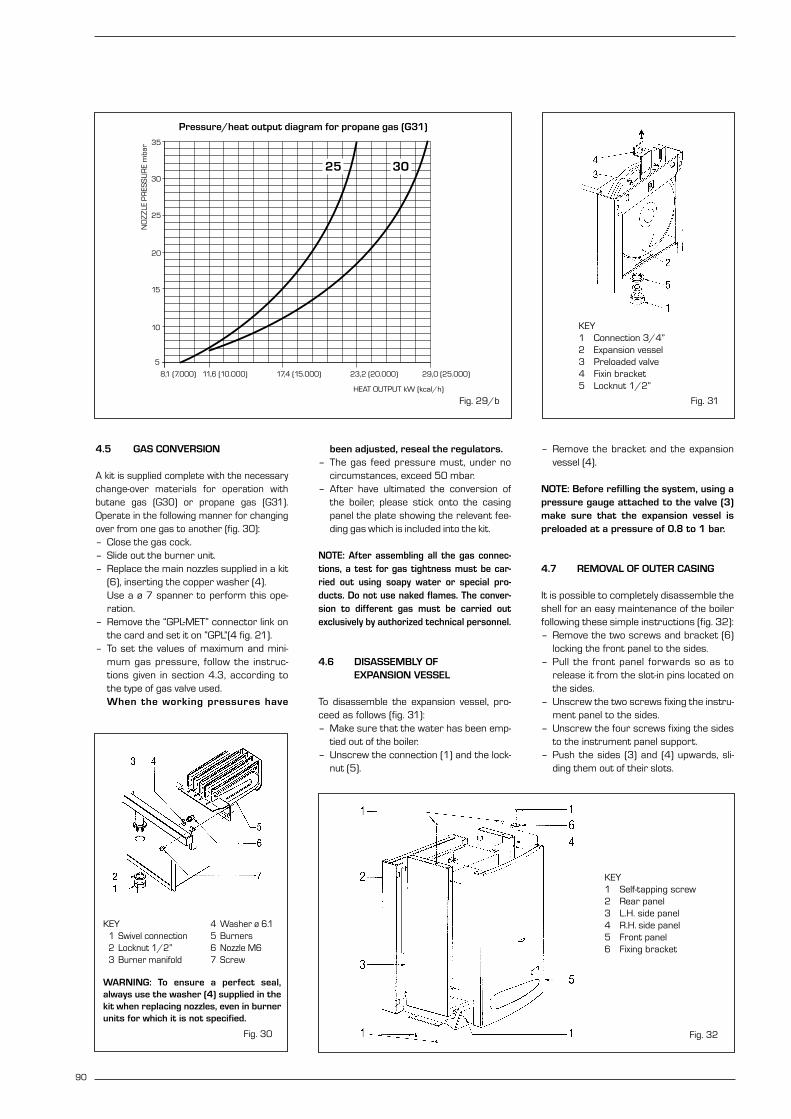
4.5 GAS CONVERSION
A kit is supplied complete with the necessarychange-over materials for operation withbutane gas (G30) or propane gas (G31).Operate in the following manner for changingover from one gas to another (fig. 30):– Close the gas cock.– Slide out the burner unit.– Replace the main nozzles supplied in a kit
(6), inserting the copper washer (4). Use a ø 7 spanner to perform this ope-ration.
– Remove the “GPL-MET” connector link onthe card and set it on “GPL”(4 fig. 21).
– To set the values of maximum and mini-mum gas pressure, follow the instruc-tions given in section 4.3, according tothe type of gas valve used. When the working pressures have
been adjusted, reseal the regulators.– The gas feed pressure must, under no
circumstances, exceed 50 mbar.– After have ultimated the conversion of
the boiler, please stick onto the casingpanel the plate showing the relevant fee-ding gas which is included into the kit.
NOTE: After assembling all the gas connec-tions, a test for gas tightness must be car-ried out using soapy water or special pro-ducts. Do not use naked flames. The conver-sion to different gas must be carried outexclusively by authorized technical personnel.
4.6 DISASSEMBLY OF EXPANSION VESSEL
To disassemble the expansion vessel, pro-ceed as follows (fig. 31):– Make sure that the water has been emp-
tied out of the boiler.– Unscrew the connection (1) and the lock-
nut (5).
– Remove the bracket and the expansionvessel (4).
NOTE: Before refilling the system, using apressure gauge attached to the valve (3)make sure that the expansion vessel ispreloaded at a pressure of 0.8 to 1 bar.
4.7 REMOVAL OF OUTER CASING
It is possible to completely disassemble theshell for an easy maintenance of the boilerfollowing these simple instructions (fig. 32):– Remove the two screws and bracket (6)
locking the front panel to the sides.– Pull the front panel forwards so as to
release it from the slot-in pins located onthe sides.
– Unscrew the two screws fixing the instru-ment panel to the sides.
– Unscrew the four screws fixing the sidesto the instrument panel support.
– Push the sides (3) and (4) upwards, sli-ding them out of their slots.
90
Fig. 32
KEY1 Self-tapping screw2 Rear panel3 L.H. side panel4 R.H. side panel5 Front panel6 Fixing bracket
Fig. 31
KEY1 Connection 3/4”2 Expansion vessel3 Preloaded valve4 Fixin bracket5 Locknut 1/2”
Fig. 30
KEY1 Swivel connection2 Locknut 1/2”3 Burner manifold
4 Washer ø 6.15 Burners6 Nozzle M67 Screw
25
20
15
10
8,1 (7.000) 11,6 (10.000) 17,4 (15.000) 23,2 (20.000)
POTENZA TERMICA kW (kcal/h)
PR
ESS
ION
E U
GEL
LO m
bar
30
35
5
29,0 (25.000)
25 30
Pressure/heat output diagram for propane gas (G31)
HEAT OUTPUT kW (kcal/h)
NO
ZZ
LEP
RES
SU
RE
mba
r
Fig. 29/b
WARNING: To ensure a perfect seal,always use the washer (4) supplied in thekit when replacing nozzles, even in burnerunits for which it is not specified.
4.8 CLEANING AND MAINTENANCE
At the end of each heating season, it isessential to have the boiler thoroughlychecked and cleaned out. Proceed as follows:– Turn the main switch off to stop electric
power reaching the boiler and close thegas feed cock.
– Remove the outer casing as described insection 4.7.
– Remove the gas burner manifold unit(fig. 30).
– To clean the burner, blow in a jet of air, soas to remove any dust particles that mayhave accumulated.
– Clean the heat exchanger, removing anydust or residue from combustion.
– When cleaning the heat exchanger orthe burners, chemical products or steelbrushes MUST NOT BE USED.
– Make sure that the tops of the burnerswith the holes are free from encrustations.
– Reassemble the items removed fromthe boiler, making sure to follow the cor-rect sequence.
– Check the chimney to make sure thatthe flue is clean.
– Check operation of the equipment andthe main burner.
– After assembly of all the gas connec-tions, these must be tested for sound-ness, using soapy water or appropriateproducts. DO NOT USE NAKED FLAMES.
Preventive maintenance and checking ofefficient operation of equipment andsafety devices must be carried out exclu-sively by authorized technical personnel.
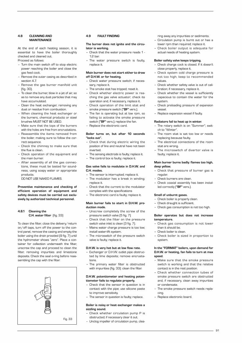
4.8.1 Cleaning the C.H. water filter (fig. 33)
To clean the filter, close the delivery/returnon/off taps, turn off the power to the con-trol panel, remove the casing and empty theboiler using the drain provided (9 fig. 7) untilthe hydrometer shows “zero”. Place a con-tainer for collection underneath the filter,unscrew the cap and proceed to clean thefilter, removing impurities and limestonedeposits. Check the seal o-ring before reas-sembling the cap with the filter.
4.9 FAULT FINDING
The burner does not ignite and the circu-lator is working.– Check that the water pressure reads 1 -
1.2 bar.– The water pressure switch is faulty,
replace it.
Main burner does not start either to drawoff D.H.W. or for heating.– Check water pressure switch; if neces-
sary, replace it.– The smoke stat has tripped; reset it.– Check whether electric power is rea-
ching the gas valve actuator; check itsoperation and, if necessary, replace it.
– Check operation of the limit stat andsmoke pressure switch (“BF” vers.).
– The fan is operating but at low rpm, sofailing to activate the smoke pressureswitch (“BF” vers.); replace the fan.
– Replace the electronic card.
Boiler turns on, but after 10 seconds“locks out”.– Check that during electric wiring the
position of line and neutral have not beeninverted.
– The sensing electrode is faulty; replace it.– The control box is faulty; replace it.
Gas valve fails to modulate in D.H.W. andC.H. modes.– The sensor is interrupted; replace it.– The modulator has a break in winding;
replace it.– Check that the current to the modulator
complies with the specifications– The electronic card is faulty; replace it.
Main burner fails to start in D.H.W. pro-duction mode.– Unscrew completely the screw of the
pressure switch valve (5 fig. 7)– Check that the filter on the pressure
switch valve inlet is clean (3 fig. 7).– Mains water charge pressure is too low;
install water-lift system.– The microswitch of the pressure switch
valve is faulty; replace it.
D.H.W. is very hot but at low flow rate.– Exchanger or D.H.W. outlet pipe obstruc-
ted by lime deposits; remove encrusta-tions.
– The primary water filter is obstructedwith impurities (fig. 33): clean the filter.
D.H.W. potentiometer and heating poten-tiometer fails to regulate properly.– Check that the sensor in question is in
contact with the pipe; use silicone pasteto improve sensitivity.
– The sensor in question is faulty; replace.
Boiler is noisy or heat exchanger makes asizzling sound.– Check whether circulation pump P is
obstructed; if necessary clear it out.– Unclog impeller of circulation pump, clea-
ring away any impurities or sediments.– Circulation pump is burnt out or has a
lower rpm than required; replace it.– Check boiler output is adequate for
actual needs of heating system.
Boiler safety valve keeps tripping.– Check charge cock is closed. If it doesn’t
close properly, replace it.– Check system cold charge pressure is
not too high; keep to recommendedvalues.
– Check whether safety valve is out of cali-bration; if necessary, replace it.
– Check whether the vessel is sufficientlycapacious to contain the water for thesystem.
– Check preloading pressure of expansionvessel.
– Replace expansion vessel if faulty.
Radiators fail to heat up in winter.– The rotary switch is on “Summer”; swit-
ch to “Winter”.– The room stat is set too low or needs
replacing because faulty.– The electrical connections of the room
stat are wrong.– The microswitch of divertor valve is
faulty; replace it.
Main burner burns badly: flames too high,deep yellow.– Check that pressure of burner gas is
regular.– Check burners are clean.– Check coaxial assembly has been instal-
led correctly (“BF” vers.).
Smell of unburnt gases.– Check boiler is properly clean.– Check draught is sufficient.– Check gas consumption is not too high.
Boiler operates but does not increasetemperature.– Check gas consumption is not lower
than it should be.– Check boiler is clean.– Check boiler is sized in proportion to
system.
In the “FORMAT” boilers, upon demand forD.H.W. or heating, fan fails to turn at maxspeed.– Make sure that the smoke pressure
switch is working and that the relativecontact is in the rest position.
– Check whether connection tubes ofsmoke pressure switch are obstructedand, if necessary, clean away impuritiesor condensate.
– The smoke pressure switch needs repla-cing.
– Replace electronic board.
91
Fig. 33

92
USER INSTRUCTIONS
WARNINGS
– In case of fault and/or incorrect equipment operation, deactivate it, without making any repairs or taking any direct
action. Contact the nearest Authorised Technical Service Centre.
– The installation of the boiler and any servicing or maintenance job must be carried out by qualified personnel. Under
no circumstances, the devices sealed by the manufacturer can be tampered with
– It is absolutely prohibited to block the intake grilles and the aeration opening of the room where the equipment is
installed.
LIGHTING AND OPERATION
BOILER IGNITION
Open the gas valve and light the applianceby turning the rotary switch to summerposition (fig. 1). The green led indicates that electricity isbeing supplied to the appliance.– With the rotary switch in the summer
position , the boiler will start-up upondemand for domestic hot water, and runat full power to reach the selected tem-perature.
The gas feeding pressure will then auto-matically vary to ensure that the requi-red temperature is kept constant.
– With the rotary switch in the winterposition , once the boiler has reachedthe value set on the heating potentiome-ter, it will start to modulate in automati-cally in order to supply the requiredpower output to the system.The operation of the boiler will be stop-ped through the intervention of the ther-mostat or timer.
TEMPERATURES ADJUSTMENT
– The D.H.W. temperature can be adju-sted by turning the knob of the D.H.W.potentiometer which has a range ofbetween 40 to 60°C (fig. 2).
– The C.H. temperature can be adjusted byturning the knob of the C.H. potentiome-ter which has a range of between 40to 80°C. To ensure optimal boiler efficiency at alltimes, we recommend not to drop belowa minimum working temperature of50°C (fig. 2).
LOCK OUT RESET OFTHE CONTROL BOX
If the burner does not ignite, the red lockout indicator will light up (fig. 3). In order to re-attempt boiler ignition, placethe rotary switch to the position andrelease it immediately, then turn it back tothe summer or winter .
Should the appliance again “lock out”,please approach the authorized technicalstaff.
APRE
0
3060
90
120
bar
°C
0
3
4
1
Fig. 1
Fig. 2
OPEN

TURNING OFF BOILER
To turn off the boiler set the switch to “OFF”and close the gas-feeding pipe tap if the boi-ler remains inoperative for a long period(fig. 1).
SYSTEM FILLING (fig. 4)
Check periodically that the thermomanome-ter shows a reading of between 1 - 1.2 bar(1), with the system cold. If the pressure drops below the blue scale(1), the boiler will not operate. To re-set the pressure, rotate the char-ging valve to the anticlockwise directionuntil the thermomanometer reading re-enters the blue scale (1). Once this operation is completed, makesure the tap is closed. In case the pressure goes above the limit,empty the exceeding pressure by openingthe pressure relief valve on any radiator. The blue part of the scale (2) indicates the
working pressure range with the heating inoperation. Should the pressure exceed thevalues of the blue scale (2), causing thesafety valve intervention, call the authorizedtechnical staff.
"25 OF - 30 OF" SMOKESAFETY DEVICE
This is a safety device against possiblesmoke emission into the ambience. The safety device switches off the gas valvewhen the return of the smokes into theambience is continuous and then dange-rous. The intervention of this device locksout the appliance because the burner is notignited. In this case, turn the rotary switchto the position (fig. 3) nd release it imme-
diately, then turn it back to the summeror winter .Should the boiler “lock out” again, youmust call the authorized technical staff.
GAS CONVERSION
Should it be necessary to convert theappliance to a different gas from the onefor which the boiler has been equipped,approach the technical staff.
CLEANING AND MAINTENANCE
At the end of each heating season, it isessential to have the boiler thoroughlychecked and cleaned out.Preventive maintenance and checking ofthe efficient operation of the equipmentand safety devices must be carried outexclusively by the authorized technicalstaff.
The boiler is supplied with an electriccable. Should this require replacement,contact exclusively with the authorizedtechnical staff.
TIME PROGRAMMER (optional)
With the selector in the “AUTO” position,the boiler operation is regulated accordingto the temperatures set for the program-med time periods. During start-up, the second selector mustbe in the “RUN” position. Programming:
– Setting the time (fig. 5)Move the selector to “”. To change thehour on the display, press the “h” button,to change the minutes, press the “m”button.To set the day, press button “1...7” untilthe arrow points to the correct day (1 =Monday ....... 7 = Sunday).
– Setting the programme (fig. 6)The programmer has 8 start-up pro-grammes and 8 shutdown options.To make programming easier, 3 start-upand 3 shutdown programmes havealready been set up for each day of theweek, as follows:
NOTE:Programmes from 7 to 16 are notpre-set.
To select programmes other than thosepre-set, move the selector to the “P”position: “0:00 1” will appear on thedisplay: the first three figures indicatethe hour and minutes, the fourth figure isthe number of the programme. Programmes with odd numbers are swit-ch-on times (daytime temperature) andare indicated on the display by a light bulbsymbol. Programmes with even numbersindicate the temperature reduction(night). Use button “1...7” to select the day of theweek (from 1 to 7), or the period (1 ÷ 5,6 - 7; 1 ÷ 6; or every day if the program-me has to be repeated every day of theweek). Set the hour and minutes usingbuttons “h” and “m”. The operation in memorized by pressingbutton “P”
93
Fig. 3
SCALA COLORE AZZURRO
APRE
0
3060
90
120
bar
°C
0
3
4
1SCALA COLORE BLU
0
3060
90
120
bar
°C
0
3
4
1
Fig. 4
Programa Hora de Hora deencendido apagado
1 06.00 -2 - 09.003 12.00 -4 - 14.005 18.00 -6 - 22.00
Fig. 5
BLUE SCALE (1)
BLUE SCALE (2)
OPEN
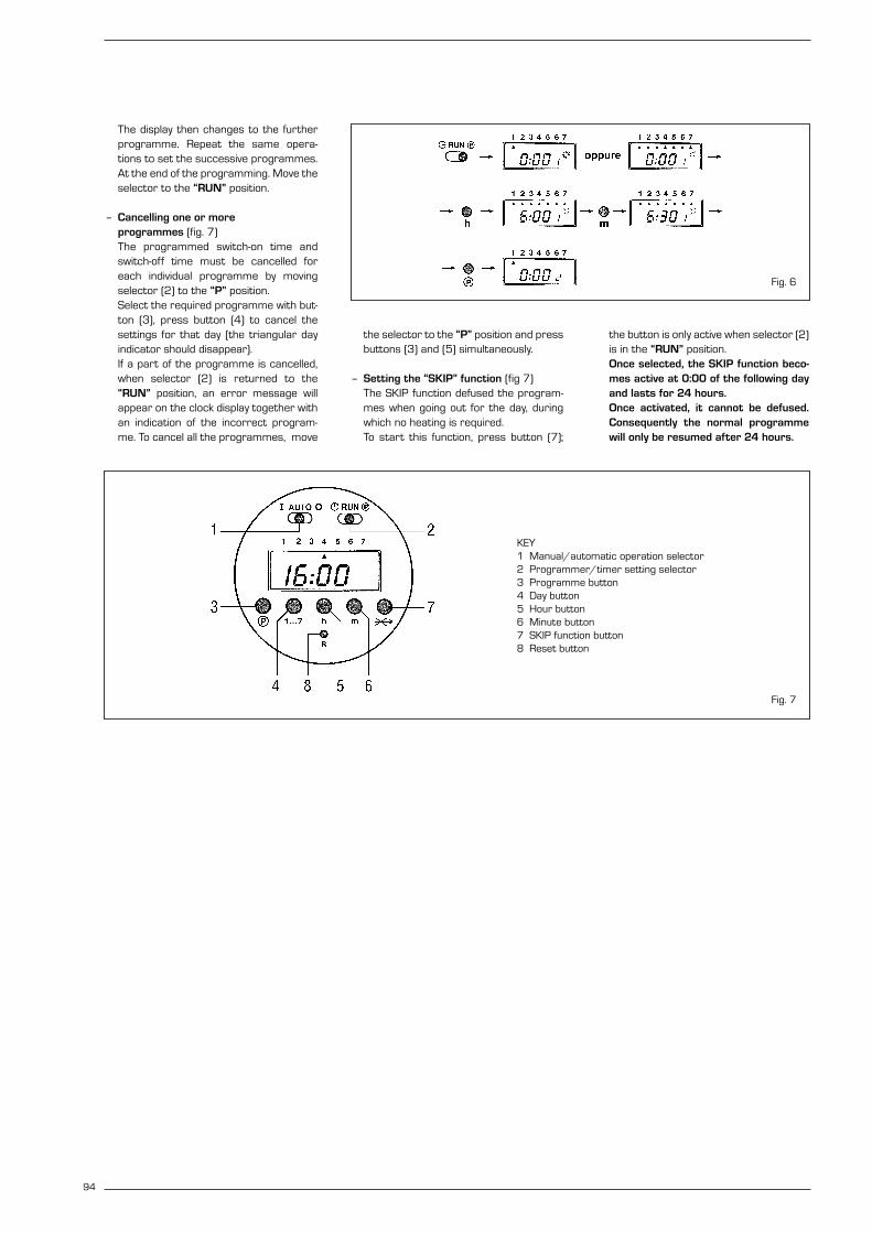
The display then changes to the furtherprogramme. Repeat the same opera-tions to set the successive programmes.At the end of the programming. Move theselector to the “RUN” position.
– Cancelling one or more programmes (fig. 7)The programmed switch-on time andswitch-off time must be cancelled foreach individual programme by movingselector (2) to the “P” position. Select the required programme with but-ton (3), press button (4) to cancel thesettings for that day (the triangular dayindicator should disappear).If a part of the programme is cancelled,when selector (2) is returned to the“RUN” position, an error message willappear on the clock display together withan indication of the incorrect program-me. To cancel all the programmes, move
the selector to the “P” position and pressbuttons (3) and (5) simultaneously.
– Setting the “SKIP” function (fig 7)The SKIP function defused the program-mes when going out for the day, duringwhich no heating is required.To start this function, press button (7);
the button is only active when selector (2)is in the “RUN” position.Once selected, the SKIP function beco-mes active at 0:00 of the following dayand lasts for 24 hours. Once activated, it cannot be defused.Consequently the normal programmewill only be resumed after 24 hours.
94
KEY1 Manual/automatic operation selector2 Programmer/timer setting selector3 Programme button4 Day button5 Hour button6 Minute button7 SKIP function button8 Reset button
Fig. 6
Fig. 7

Format C
installation and servicing instructions

These appliances comply with the S.E.D.B.U.K. scheme, band “D”
SIME COMBINATION BOILERSInstaller checklist
Please remember to carry out the following checks after installation. This will achieve complete customer satis-
faction, and avoid unnecessary service calls. A charge will be made for a service visit where the fault is not due to
a manufacturing defect.
– Has a correct by-pass been fitted and adjusted?
– Has the system and boiler been flushed?
– Is the system and boiler full of water, and the correct pressure showing on the pressure gauge?
– Is the Auto Air Vent open?
– Has the pump been rotated manually?
– Is the gas supply working pressure correct?
– Is the boiler wired correctly? (See installation manual).
– Has the D.H.W. flow rate been set to the customer requirements?
– Has the customer been fully advised on the correct use of the boiler, system and controls?
– Has the log book provided been completed?
Please refer to commissioning instructions for filling in the log book
Note: All CORGI registered installers carry a CORGI ID Card. You can check your installer is CORGI Registered by calling 01256 372300

1 TECHNICAL FEATURES AND DIMENSIONS
1.1 INTRODUCTION . . . . . . . . . . . . . . . . . . . . . . . . . . . . . . . . . . . . . . . . . . . . . . . . . . . . . . . . . . . . . . . . . . . . . . . . . . . . . 1
1.2 DIMENSIONAL DETAILS
1.3 GENERAL DATA . . . . . . . . . . . . . . . . . . . . . . . . . . . . . . . . . . . . . . . . . . . . . . . . . . . . . . . . . . . . . . . . . . . . . . . . . . . . . 2
1.4 HYDRAULIC CIRCUIT . . . . . . . . . . . . . . . . . . . . . . . . . . . . . . . . . . . . . . . . . . . . . . . . . . . . . . . . . . . . . . . . . . . . . . . . . 3
2 GENERAL REQUIREMENTS FOR INSTALLATION
2.1 STATUTORY REQUIREMENTS . . . . . . . . . . . . . . . . . . . . . . . . . . . . . . . . . . . . . . . . . . . . . . . . . . . . . . . . . . . . . . . . . 4
2.2 BOILER POSITION
2.3 FLUE TERMINAL POSITION
2.4 VENTILATION REQUIREMENTS . . . . . . . . . . . . . . . . . . . . . . . . . . . . . . . . . . . . . . . . . . . . . . . . . . . . . . . . . . . . . . . . 5
2.5 GAS SUPPLY
2.6 ELECTRICITY SUPPLY
2.7 EXTERNAL CONTROLS
2.8 WATER SYSTEMS - GENERAL
2.9 REQUIREMENTS FOR SEALED WATER SYSTEMS
2.10 D.H.W. SYSTEMS . . . . . . . . . . . . . . . . . . . . . . . . . . . . . . . . . . . . . . . . . . . . . . . . . . . . . . . . . . . . . . . . . . . . . . . . . . . . 7
3 INSTALLING THE BOILER
3.1 UNPACKING THE BOILER . . . . . . . . . . . . . . . . . . . . . . . . . . . . . . . . . . . . . . . . . . . . . . . . . . . . . . . . . . . . . . . . . . . . . 8
3.2 FIXING THE WALL MOUNTING BRACKET
3.3 HANGING THE BOILER
3.4 FLUE AND TERMINAL PREPARATION
3.5 FLUE AND TERMINAL INSTALLATION . . . . . . . . . . . . . . . . . . . . . . . . . . . . . . . . . . . . . . . . . . . . . . . . . . . . . . . . . . . 10
3.6 SEPARATE DUCTS . . . . . . . . . . . . . . . . . . . . . . . . . . . . . . . . . . . . . . . . . . . . . . . . . . . . . . . . . . . . . . . . . . . . . . . . . . . 11
3.7 WATER CONNECTIONS . . . . . . . . . . . . . . . . . . . . . . . . . . . . . . . . . . . . . . . . . . . . . . . . . . . . . . . . . . . . . . . . . . . . . . . 13
3.8 GAS CONNECTIONS
3.9 SAFETY VALVE CONNECTION
3.10 WIRING INSTRUCTIONS . . . . . . . . . . . . . . . . . . . . . . . . . . . . . . . . . . . . . . . . . . . . . . . . . . . . . . . . . . . . . . . . . . . . . . 14
3.11 TIME-CLOCK INSTRUCTIONS
4 COMMISSIONING AND TESTING
4.1 FILLING THE WATER SYSTEM . . . . . . . . . . . . . . . . . . . . . . . . . . . . . . . . . . . . . . . . . . . . . . . . . . . . . . . . . . . . . . . . . 14
4.2 COMMISSIONING THE BOILER
4.3 SETTING THE C.H. INPUT . . . . . . . . . . . . . . . . . . . . . . . . . . . . . . . . . . . . . . . . . . . . . . . . . . . . . . . . . . . . . . . . . . . . . 15
4.4 SETTING THE D.H.W. FLOWRATE
4.5 FINAL CHECKS
4.6 USER’S INSTRUCTIONS
5 ROUTINE SERVICING INSTRUCTIONS
5.1 MAIN BURNER ASSEMBLY . . . . . . . . . . . . . . . . . . . . . . . . . . . . . . . . . . . . . . . . . . . . . . . . . . . . . . . . . . . . . . . . . . . 16
5.2 FAN ASSEMBLY
CONTENTS

5.3 HEAT EXCHANGER . . . . . . . . . . . . . . . . . . . . . . . . . . . . . . . . . . . . . . . . . . . . . . . . . . . . . . . . . . . . . . . . . . . . . . . . . . . 16
5.4 RE-ASSEMBLY
5.5 RE-COMMISSIONING
6 FAULT FINDING
6.1 EARTH CONTINUITY CHECK . . . . . . . . . . . . . . . . . . . . . . . . . . . . . . . . . . . . . . . . . . . . . . . . . . . . . . . . . . . . . . . . . . 17
6.2 SHORT CIRCUIT CHECK
6.3 POLARITY CHECK
6.4 RESISTANCE TO EARTH CHECK
6.5 FAULT FINDING LEDS
6.6 C.H. MODE - FAULT FINDING . . . . . . . . . . . . . . . . . . . . . . . . . . . . . . . . . . . . . . . . . . . . . . . . . . . . . . . . . . . . . . . . . . 18
6.7 D.H.W. MODE - FAULT FINDING . . . . . . . . . . . . . . . . . . . . . . . . . . . . . . . . . . . . . . . . . . . . . . . . . . . . . . . . . . . . . . . . 19
7 INTERNAL WIRING DIAGRAMS AND VIEWS
7.1 FUNCTIONAL FLOW WIRING DIAGRAM . . . . . . . . . . . . . . . . . . . . . . . . . . . . . . . . . . . . . . . . . . . . . . . . . . . . . . . . 20
7.2 INTERNAL VIEW . . . . . . . . . . . . . . . . . . . . . . . . . . . . . . . . . . . . . . . . . . . . . . . . . . . . . . . . . . . . . . . . . . . . . . . . . . . . . 21
8 REPLACEMENT OF PARTS
8.1 HEAT EXCHANGER . . . . . . . . . . . . . . . . . . . . . . . . . . . . . . . . . . . . . . . . . . . . . . . . . . . . . . . . . . . . . . . . . . . . . . . . . . . 22
8.2 COMBUSTION CHAMBER INSULATION
8.3 FAN ASSEMBLY
8.4 MAIN BURNER
8.5 IGNITION/DETECTION ELECTRODE
8.6 GAS VALVE
8.7 AIR PRESSURE SWITCH . . . . . . . . . . . . . . . . . . . . . . . . . . . . . . . . . . . . . . . . . . . . . . . . . . . . . . . . . . . . . . . . . . . . . . 23
8.8 OVERHEAT THERMOSTAT
8.9 THERMISTOR
8.10 DRIVER PCB
8.11 PUMP MOTOR
8.12 D.H.W. HEAT EXCHANGER . . . . . . . . . . . . . . . . . . . . . . . . . . . . . . . . . . . . . . . . . . . . . . . . . . . . . . . . . . . . . . . . . . . . 24
8.13 DIVERTOR VALVE - COMPLETE
8.14 DIVERTOR VALVE - MICROSWITCH ASSEMBLY
8.15 C.H. EXPANSION VESSEL
8.16 THERMOHYDROMETER
8.17 SAFETY VALVE
8.18 AUTOMATIC AIR VENT
8.19 TIME CLOCK
9 SHORT LIST OF PARTS . . . . . . . . . . . . . . . . . . . . . . . . . . . . . . . . . . . . . . . . . . . . . . . . . . . . . . . . . . . . . . . . . . . . . . 25
71
855
165
335
125 60
ø 6
0/
10
0
70
0
K
11
0
L
55
70 70 70 70 ==R M E UG
22
1.1 INTRODUCTION
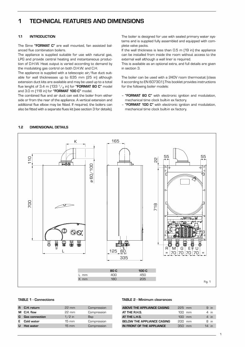
The Sime “FORMAT C” are wall mounted, fan assisted bal-anced flue combination boilers.The appliance is supplied suitable for use with natural gas,LPG and provide central heating and instantaneous produc-tion of D.H.W. Heat output is varied according to demand bythe modulating gas control on both D.H.W. and C.H. The appliance is supplied with a telescopic air/flue duct suit-able for wall thicknesses up to 635 mm (25 in) althoughextension duct kits are available and may be used up to a totalflue lenght of 3.4 m (133 7/8 in) for “FORMAT 80 C” modeland 3.0 m (118 in) for “FORMAT 100 C” model.The combined flue and air duct can exit the boiler from eitherside or from the rear of the appliance. A vertical extension andadditional flue elbow may be fitted. If required, the boilers canalso be fitted with a separate flues kit (see section 3 for details).
The boiler is designed for use with sealed primary water sys-tems and is supplied fully assembled and equipped with com-plete valve packs. If the wall thickness is less than 0.5 m (19 in) the appliancecan be installed from inside the room without access to theexternal wall although a wall liner is required. This is available as an optional extra, and full details are givenin section 3.
The boiler can be used with a 240V room thermostat (classII according to EN 60730.1).This booklet provides instructionsfor the following boiler models:
– “FORMAT 80 C” with electronic ignition and modulation,mechanical time clock built-in ex factory.
– “FORMAT 100 C” with electronic ignition and modulation,mechanical time clock built-in ex factory.
1
1 TECHNICAL FEATURES AND DIMENSIONS
TABLE 2 - Minimum clearances
ABOVE THE APPLIANCE CASING 225 mm 9 in
AT THE R.H.S. 100 mm 4 in
AT THE L.H.S. 100 mm 4 in
BELOW THE APPLIANCE CASING 200 mm 8 in
IN FRONT OF THE APPLIANCE 350 mm 14 in
TABLE 1 - Connections
R C.H. return 22 mm Compression
M C.H. flow 22 mm Compression
G Gas connection 1/2 in Bsp
E Cold water 15 mm Compression
U Hot water 15 mm Compression
1.2 DIMENSIONAL DETAILS
80 C 100 CL mm 400 450K mm 180 205
Fig. 1

2
1.3 GENERAL DATA
TABLE 3a - Nominal boiler ratings (5 minutes after lighting) for “FORMAT 80 C” (G20)
MODE OUTPUT INPUT (G.C.V.) BURNER PRESS. (G30) BURNER PRESS. (G31)
kW Btu/h kW Btu/h mbar inwg mbar inwg
CENTRAL HEATING RANGE 9.0 31,000 12.0 42,000 5.9 2.4 7.7 3.1
10.6 36,000 14.1 48,000 7.9 3.2 10.3 4.1
12.3 42,000 16.2 55,000 10.2 4.1 13.2 5.3
14.1 48,000 18.2 62,000 12.7 5.1 16.3 6.5
X* (G31) 15.9 54,000 20.3 69,000 15.4 6.2 19.6 7.9
X* (G30) 17.7 60,000 22.4 76,000 18.4 7.4 23.2 9.3
19.6 67,000 24.5 84,000 21.5 8.6 26.9 10.8
21.5 73,000 26.6 90,000 24.8 10.0 30.8 12.4
23.4 80,000 28.7 98,000 28.3 11.4 36.5 14.7
DOMESTIC HOT WATER Max. 23.4 80,000 28.7 98,000 28.3 11.4 36.5 14.7
Min. 9.0 31,000 12.0 42,000 5.9 2.4 7.7 3.1
* Factory setting
MODE OUTPUT INPUT (G.C.V.) BURNER PRESSURE
kW Btu/h kW Btu/h mbar inwg
CENTRAL HEATING RANGE 9.0 31,000 12.0 42,000 2.4 0.9
10.6 36,000 14.1 48,000 3.2 1.3
12.3 42,000 16.2 55,000 4.1 1.7
14.1 48,000 18.2 62,000 5.2 2.1
X* 15.9 54,000 20.3 69,000 6.3 2.5
17.7 60,000 22.4 76,000 7.5 3.0
19.6 67,000 24.5 84,000 8.9 3.6
21.5 73,000 26.6 90,000 10.3 4.1
23.4 80,000 28.7 98,000 11.8 4.7
DOMESTIC HOT WATER Max. 23.4 80,000 28.7 98,000 11.8 4.7
Min. 9.0 31,000 12.0 42,000 2.4 0.9
* Factory setting
TABLE 3c - Nominal boiler ratings (5 minutes after lighting) for “FORMAT 100 C” (G20-G31)
MODE OUTPUT INPUT (G.C.V.) BURNER PRESS. (G20) BURNER PRESS. (G31)
kW Btu/h kW Btu/h mbar inwg mbar inwg
CENTRAL HEATING RANGE 11.4 39,000 15.0 51,000 2.6 1.0 7.1 2.9
13.5 46,000 17.5 60,000 3.5 1.4 9.4 3.8
15.6 53,000 20.0 68,000 4.5 1.8 12.1 4.8
17.7 60,000 22.5 77,000 5.6 2.3 14.9 6.0
X* (G20) 19.8 68,000 25.0 86,000 6.8 2.7 18.0 7.2
22.0 75,000 27.6 94,000 8.2 3.3 21.3 8.6
24.2 83,000 30.1 103,000 9.6 3.8 24.8 10.0
26.5 90,000 32.6 111,000 11.1 4.5 28.5 11.4
28.8 98,000 35.1 120,000 12.7 5.1 36.5 14.7
DOMESTIC HOT WATER Max. 28.8 98,000 35.1 120,000 12.7 5.1 36.5 14.7
Min. 11.4 39,000 15.0 51,000 2.6 1.0 7.1 2.9
* Factory setting
TABLE 3b - Nominal boiler ratings (5 minutes after lighting) for “FORMAT 80 C” (G30-G31)

3
1
2
3
4
22
5
7
8
27
11
14
10
9
6
1612
18
2813
192120
17
U E G M R
1.4 HYDRAULIC CIRCUIT
KEY1 Fan2 Water-gas exchanger3 Combustion chamber4 Gas valve5 D.H.W. exchanger6 Divertor valve7 NTC sensor8 100°C safety thermostat9 Air relief valve
10 Circulation pump11 Expansion vessel12 Safety valve13 Drain plug14 Water flow switch16 Automatic by-pass17 D.H.W. filter18 C.H. return cock19 C.H. flow cock20 D.H.W. cock21 Gas cock22 Fixing jig27 Thermometer sensor28 Hydrometer
80 C 100 C
Main burner injectors No off 12 14
Dia (G20) mm 1.3 1.3
Dia (G30 - G31) mm 0.77 0.78
Water capacity l (gal) 3.4 (0.75) 4.7 (1.00)
Minimum water flow D.H.W. l/min (gal/min) 2 (0.5) 2 (0.5)
D.H.W. flow rate
at a temperature rise of 30°C l/min (gal/min) 11.2 (2.5) 13.8 (3.0)
35°C l/min (gal/min) 9.6 (2.1) 11.9 (2.6)
Static head Minimum bar (psi) 0.5 (7.3) 0.5 (7.3)
Maximum bar (psi) 3.0 (43.5) 3.0 (43.5)
D.H.W. pressure Minimum bar (psi) 0.5 (7.3) 0.5 (7.3)
Maximum bar (psi) 7.0 (102) 7.0 (102)
Weight Empty kg (lb) 38 (84) 40 (88)
Total (full) kg (lb) 41.4 (91) 44.7 (98)
Electrical supply 230 V - 50 Hz, Fused at 3 A
Internal fuse Line: F 1.6 A
Maximum power consumption Watt 150 160
Maximum gas consumpt. (G20) m3/h (ft3/h) 2.73 (96) 3.34 (118)
Maximum gas consumpt. (G30 - G31) kg/h (lb/h) 2.02 - 1.99 (4.45 - 4.39) 2.48 - 2.44 (5.47 - 5.38)
Max. working temperature °C (F) 95 (203) 95 (203)
Integral exp. vessel capacity l (gal) 6 (1.32) 8 (1.76)
TABLE 4 - General specifications
Fig. 2

2.1 STATUTORY REQUIREMENTS
GAS SAFETY (INSTALLATION AND USE) REGULATIONS (asamended). It is the law that all gas appliances are installed bya registered person, in accordance with the above regula-tions. Failure to install appliances correctly could lead to pros-ecution. It is in your own interest, and that of safety, to ensurethat the law is complied with.In addition to the above regulations, this appliance must beinstalled in accordance with the current IEE WiringRegulations (BS 7671), Local Building Regulations, theBuilding Standards (Scotland) (Consolidation) Regulations,Byelaws of the local water undertaking, and Health and SafetyDocument No 635 “The Electricity at Work Regulations1989”. It should also be in accordance with the relevant rec-ommendations in the current editions of the following BritishStandards and Codes of Practice: BS5449, BS5546,BS5440:1, BS5440:2, BS6798, BS6891, and BG.DM2,BS7074, and BS5482 for propane installations.
Manufacturer’s instructions must NOT be taken in any wayas over-riding statutory obligations.
2.2 BOILER POSITION
In siting the combination boiler, the following limitations MUSTbe observed:– The boiler is not suitable for external installation. The posi-
tion selected for installation should be within the building,unless otherwise protected by a suitable enclosure, andMUST allow adequate space for installation, servicing, andoperation of the appliance, and for air circulation around it(section 2.4).
– This position MUST allow for a suitable flue termination tobe made. The combination boiler must be installed on aflat vertical wall which is capable of supporting the weightof the appliance, and any ancillary equipment.
– If the combination boiler is to be fitted in a timber framedbuilding it should be fitted in accordance with the Instituteof Gas Engineers document for Gas Installations In TimberFrame Housing, Reference 16E/UP/7: 1998. If in doubt,advice must be sought from the gas supplier.
– If the appliance is installed in a room containing a bath orshower, any electrical switch or control utilising mainselectricity must be so situated that it cannot be touchedby a person using the bath or shower. Attention is drawnto the requirements of the current I.E.E. Wiring Regula-tions (BS 7671), and in Scotland the electrical provisionsof the Building Regulations applicable in Scotland.
– A compartment used to enclose the appliance MUST bedesigned and constructed specifically for this purpose. Anexisting cupboard, or compartment, may be used provid-ed it is modified accordingly.
– Where installation will be in an unusual location, specialprocedures may be necessary. BS6798 gives detailedguidance on this aspect.
2.3 FLUE TERMINAL POSITION
Detailed recommendations for flue installation are given inBS5440:1. The following notes are for general guidance:– The boiler MUST be installed so that the terminal is
exposed to the external air.
– It is important that the position of the terminal allows freepassage of air across it at all times.
– It is ESSENTIAL TO ENSURE, in practice that products ofcombustion discharging from the terminal cannot re-enter the building, or any other adjacent building, throughventilators, windows, doors, other sources of natural airinfiltration, or forced ventilation/air conditioning. If thisdoes occur, the appliance MUST be turned OFF IMMEDI-ATELY and the gas supplier consulted.
– The minimum acceptable dimensions from the terminal toobstructions and ventilation openings are specified in fig. 3.
– If the terminal discharges into a pathway or passagewaycheck that combustion products will not cause nuisanceand that the terminal will not obstruct the passageway.
– Where the lowest part of the terminal is fitted less than 2m (78 in) above ground, above a balcony or above a flatroof to which people have access, the terminal MUST be
4
Terminal position
Directly below an openable window, air
vent or any other ventilation opening
Below guttering, drain pipes or soil pipes
Below eaves, balconies or carport roof
From vertical drain pipes or soil pipes
From internal or external corners
Above adjacent ground, roof or bal-
cony level
From a surface facing the terminal
From a terminal facing the terminal
From an opening in the carport (eg
door, window into dwelling)
Vertically from a terminal on the
same wall
Horizontally from a terminal on the
same wall
Adjacent to opening
A
B
C/D
E
F
G
H
I
J
K
L
M
Minimum spacing
300 mm 12 in
75 mm 3 in
200 mm 8 in
75 mm 3 in
300 mm 12 in
300 mm 12 in
600 mm 24 in
1,200 mm 48 in
1,200 mm 48 in
1,500 mm 60 in
300 mm 12 in
300 mm 12 in
TABLE 5
2 GENERAL REQUIREMENTS FOR INSTALLATION
Fig. 3
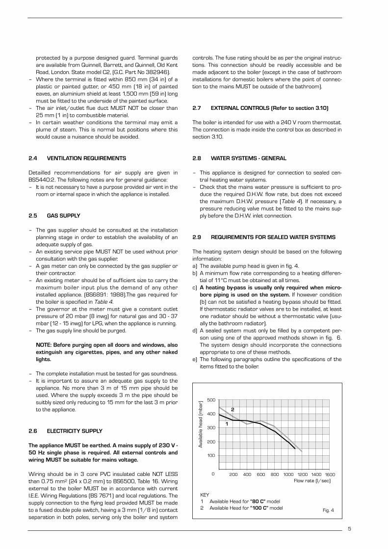
protected by a purpose designed guard. Terminal guardsare available from Quinnell, Barrett, and Quinnell, Old KentRoad, London. State model C2, (G.C. Part No 382946).
– Where the terminal is fitted within 850 mm (34 in) of aplastic or painted gutter, or 450 mm (18 in) of paintedeaves, an aluminium shield at least 1,500 mm (59 in) longmust be fitted to the underside of the painted surface.
– The air inlet/outlet flue duct MUST NOT be closer than25 mm (1 in) to combustible material.
– In certain weather conditions the terminal may emit aplume of steam. This is normal but positions where thiswould cause a nuisance should be avoided.
2.4 VENTILATION REQUIREMENTS
Detailled recommendations for air supply are given inBS5440:2. The following notes are for general guidance:– It is not necessary to have a purpose provided air vent in the
room or internal space in which the appliance is installed.
2.5 GAS SUPPLY
– The gas supplier should be consulted at the installationplanning stage in order to establish the availability of anadequate supply of gas.
– An existing service pipe MUST NOT be used without priorconsultation with the gas supplier.
– A gas meter can only be connected by the gas supplier ortheir contractor.
– An existing meter should be of sufficient size to carry themaximum boiler input plus the demand of any otherinstalled appliance. (BS6891: 1988).The gas required forthe boiler is specified in Table 4.
– The governor at the meter must give a constant outletpressure of 20 mbar (8 inwg) for natural gas and 30 - 37mbar (12 - 15 inwg) for LPG, when the appliance is running.
– The gas supply line should be purged.
NOTE: Before purging open all doors and windows, alsoextinguish any cigarettes, pipes, and any other nakedlights.
– The complete installation must be tested for gas soundness.– It is important to assure an adequate gas supply to the
appliance. No more than 3 m of 15 mm pipe should beused. Where the supply exceeds 3 m the pipe should besuitbly sized only reducing to 15 mm for the last 3 m priorto the appliance.
2.6 ELECTRICITY SUPPLY
The appliance MUST be earthed. A mains supply of 230 V -50 Hz single phase is required. All external controls andwiring MUST be suitable for mains voltage.
Wiring should be in 3 core PVC insulated cable NOT LESSthan 0.75 mm2 (24 x 0.2 mm) to BS6500, Table 16. Wiringexternal to the boiler MUST be in accordance with currentl.E.E. Wiring Regulations (BS 7671) and local regulations. Thesupply connection to the flying lead provided MUST be madeto a fused double pole switch, having a 3 mm (1/8 in) contactseparation in both poles, serving only the boiler and system
controls. The fuse rating should be as per the original instruc-tions. This connection should be readily accessible and bemade adjacent to the boiler (except in the case of bathroominstallations for domestic boilers where the point of connec-tion to the mains MUST be outside of the bathroom).
2.7 EXTERNAL CONTROLS (Refer to section 3.10)
The boiler is intended for use with a 240 V room thermostat.The connection is made inside the control box as described insection 3.10.
2.8 WATER SYSTEMS - GENERAL
– This appliance is designed for connection to sealed cen-tral heating water systems.
– Check that the mains water pressure is sufficient to pro-duce the required D.H.W. flow rate, but does not exceedthe maximum D.H.W. pressure (Table 4). If necessary, apressure reducing valve must be fitted to the mains sup-ply before the D.H.W. inlet connection.
2.9 REQUIREMENTS FOR SEALED WATER SYSTEMS
The heating system design should be based on the followinginformation:a) The available pump head is given in fig. 4.b) A minimum flow rate corresponding to a heating differen-
tial of 11°C must be obtained at all times.c) A heating by-pass is usually only required when micro-
bore piping is used on the system. If however condition(b) can not be satisfied a heating by-pass should be fitted.If thermostatic radiator valves are to be installed, at leastone radiator should be without a thermostatic valve (usu-ally the bathroom radiator).
d) A sealed system must only be filled by a competent per-son using one of the approved methods shown in fig. 6.The system design should incorporate the connectionsappropriate to one of these methods.
e) The following paragraphs outline the specifications of theitems fitted to the boiler.
5
0 200 1600140012001000800600400
PORTATA (l/h)
PR
EVA
LEN
ZA
RES
IDU
A (m
bar)
500
400
100
200
300
30
25
KEY1 Available Head for “80 C” model2 Available Head for “100 C” model
Flow rate (l/sec)
Ava
ilabl
e he
ad (
mba
r)
Fig. 4
1
2

6
TYPICAL SYSTEM DESIGN
ALTERNATIVE METHODS OF FILLING A SEALED SYSTEM
NOTE: A drain cock should be installed at the lowest point of the heating circuit and beneath the appliance.
NOTES:– When it is not possible to avoid a situation where the initial system pressure and static head are equal a manually fit-
ted top up container should be fitted as shown above.Take note of the requirements relative to container capacity: height above system, inclusion of a non-return valve,stop cock and automatic air vent in the feed pipe, as shown in fig. 5.Note also the feed pipe connection is made to the heating return as close to the appliance as possible.
– The Local Water Undertaking MUST approve ALL connections between the system and a water storage cistern orwater main supplying D.H.W.
METHOD 1 (complies with BS6798.1987) METHOD 2 (complies with BS6798.1987)
Fig. 5
Fig. 6

2.9.1 Pump
The available head shown in fig. 4 is that in excess of the appli-ance hydraulic resistance, i.e. that available for the system atany given heating load up to the maximum output in C.H.mode. Never reduce the pump speed below maximum as thiswill reduce D.H.W. output. The pump speed is indicated on theside of the pump speed selector switch (if fitted).
2.9.2 System volume (total water content)
The following Table gives the maximum system volume thatthe integral expansion vessel can sustain under differentcharge pressure conditions. If the system volume exceeds that shown, an additional expan-sion vessel must be fitted and connected to the heating systemprimary return pipe as close as possible to the appliance. If an extra vessel is required, ensure that the total capacity ofboth vessels is adequate. Further details are available in thecurrent issues of BS5449 and BS6798.
NOTE: If the pressure gauge indicates 2.65 bar or greaterwhen the appliance is at maximum temperature with allradiators in circulation an extra expansion vessel isrequired.
2.9.3 Pressure gauge
A pressure gauge is mounted on the appliance facia panel.
2.9.4 Safety valve
A safety valve set at 3 bar (43.5 psi) is fitted to the applianceand a discharge pipe is routed to outside of the appliance.This discharge pipe should be extended to terminate safelyaway from the appliance and where a discharge would not
cause damage to persons or property but would be detected.The pipe should be able to withstand boiling water, be a mini-mum of 15 mm in diameter, and not include any horizontalruns prone to freezing.
2.10 D.H.W. SYSTEMS
– The authority of the local Water Company should beobtained before the appliance is connected to the coldwater mains supply. Check that the mains supply pres-sure is within the prescribed limits (Table 4).If necessary, a pressure reducing valve should be fitted tothe mains supply before the D.H.W. inlet connection.
– The final 600 mm (24 in) of the mains supply pipe to theboiler must be copper.
– A maximum D.H.W. flow rate of: 10.3 l/m (2.3 gpm) for“FORMAT 80 C”, 13 l/m (2.9 gpm) for “FORMAT 100 C”is recommended. Higher flow rates will not damage theappliance but may lower the water temperature below anacceptable level.
– If the appliance is installed in an area where the tempo-rary hardness of the water supply is high, say over 150ppm, the fitting of an in line scale inhibitor may be anadvantage. Consult the Local Water Undertaking if indoubt.
– Devices capable of preventing the flow of expansion water:e.g. non return valves and/or loose-jumpered stop cocksshould not be fitted unless separate arrangements aremade for expansion water.
– For specific information relating to fittings (eg. Showers,washing machines etc.) suitable for connection in theD.H.W. circuit, consult the Local Water Undertaking, how-ever the following information is given for guidance.
2.10.1 Domestic hot/cold water supply taps and mixing taps
All equipment designed for use at mains water pressure issuitable.
2.10.2 Showers
Any mains pressure shower is suitable, but if the unit has aloose head which may become immersed in bath water eitheran anti-syphonage device must be fitted, or the length of theflexible hose must be reduced so that it cannot fall closer than13 mm (1/2 in) to the top of the bath.
2.10.3 Bidets
Providing that the appliance is of the over-rim flushing type, theoutlets are shrouded and it is impossible to attach a temporaryhand held spray, no anti syphonage device is necessary.
7
Vessel charge and initial system
pressure
Total water content of system
using 6 l (1.32 gal) capacity expan-
sion vessel supplied with appliance
(“FORMAT 80 C”)
Total water content of system
using 8 l (1.76 gal) capacity expan-
sion vessel supplied with appliance
(“FORMAT 100 C”)
For systems having a larger capaci-
ty multiply the total system capacity
in litres (gal) by the factor to obtain
the total minimum expansion vessel
capacity required litres (gal)
bar
psi
l
gal
l
gal
0.5
7.3
72
15.8
96
21.1
.0833
1.5
21.8
38
8.3
51
11.2
.156
1.0
14.5
55
12.1
74
16.2
.109
TABLE 6

3.1 UNPACKING THE BOILER
The standard appliance is supplied in two separate card-board cartons. In addition up to two extension duct kits maybe used. If the appliance is to be installed without access tothe outside wall, the wall liner will also be required. Unpackeach carton and check the contents against the followinglists:
Appliance package:
– combination boiler (assembled);– installation and servicing instructions;– users instructions;– wall mounting templates (paper);– wall mounting bracket;– fixing screws with wall plugs;– plastic bags containing:
– gas service cock;– C.H. F/R isolation valves;– D.H.W. isolation valve;– D.H.W. elbow connection;– associated fixing screws;– associated gaskets;– safety valve discharge pipe.
Flue Package:
– telescopic flue;– junction collar with protective metal sleeve;– flue elbow with gasket;– rubber sealing rings;– associated lip seals and screws.
3.2 FIXING THE WALL MOUNTING BRACKET
Before installing the appliance ensure that the chosen loca-tion is suitable (section 2.2) and that the requirements forflue position, (section 2.3), and minimum clearances, (Table 2)are satisfied. These minimum clearances are essential to pro-vide access for servicing, and are included on the wall mount-ing templates.– Open the paper wall mounting templates. If a rear flue is
to be used, discard the side templates and secure therear template in the desired position. For a side flue appli-cation, secure both the rear and appropriate side tem-plate in position.
– Mark the position of the two wall mounting bracket fixingholes and the flue/air duct hole on the appropriatewall(s).
– Remove the template(s) and drill the two fixing holes usinga 10 mm masonry drill. Fit the plastic plugs provided.
– Cut the hole in the wall for the flue/air duct. The diame-ter should not be less than 100 mm (4 in) and must behorizontal. If the hole is not accessible from the outsideof the building, its minimum diameter should be suffi-cient to allow the insertion of the wall liner (130 mm - 51/4 in diameter) which will be sealed with mortar. Referto fig. 13.
– Accurately measure the wall thickness, and note thisdimension for later use.
– Secure the wall mounting bracket in position using thescrews provided. Ensure that it is the correct way up, asindicated in fig. 7.
3.3 HANGING THE BOILER
– Lift the appliance into position. The upper cross memberlocates onto the wall mounting bracket.
– Screw in the wall mounting bracket adjusting screws untilthe appliance is secure and vertical.
3.4 FLUE DUCTS PREPARATION
If the wall thickness is less than 0.5 m (19 in) the flue/air ductmay be fitted without access to the outside wall.
3.4.1 Flue/air duct lenghts
– Determine whether an extension duct is required with ref-erence to the Z dimension shown in figs. 9-10-11. Alterna-tively max. flue lenghts information is given in Table 7.
– If no extension ducts are required, procede to 3.5.– If an extension duct or ducts is/are to be used, the flue and
air ducts should be joined before proceeding to the next sec-tion. The extension ducts should be joined to each other andto the standard ducts using the following procedure (fig. 8);
8
KEY1 Wall mounting bracket2 Plastic wall plug (2 Off)3 Woodscrew (2 Off)4 Washer (2 Off)5 Adjustment screw (2 Off)
3 INSTALLING THE BOILER
Fig. 7
Fig. 8

– For the flue ducts in turn, push the plain end of the stan-dard and (if using two or three extensions) extension ductinto the swaged end of the extension duct(s).
– Push an air duct in to the clamp. Join the air ducts (largerducts) and tighten the screws an the clamp to connect them.
3.4.2 Cutting the flue/air duct extensionto the correct length
Rear flue outlet (Only - fig. 9)
– Select the air duct (larger duct) and starting at the formedend, ‘mark off’ the length to be cut which is the wall thick-ness X + 90 mm (3 1/2 in).
Side flue outlet (Only - fig. 10)
Right hand side– Select the air duct (larger duct) and starting at the formed
end, ‘mark off’ the length to be cut which is the wall thick-ness X + the clearance Y plus 105 mm (4 1/8 in) for the“FORMAT 80 C” model and 130 mm (5 1/8 in) for the“FORMAT 100 C” model.
Left hand side– Select the air duct (larger duct) and starting at the formed
end, ‘mark off’ the length to be cut which is the wall thick-ness X + the clearance Y plus 145 mm (5 3/4 in) for the“FORMAT 80 C” model and 170 mm (6 3/4 in) for the“FORMAT 100 C” model.
All installations
– Cut the air duct square to the mark and remove all burrsand sharp edges.
9
Fig. 9
TABLE 7 - Maximum flue lengths (measured from appliance casing to outside wall face)
FORMAT 80 C Rear outlet R.H. side outlet L.H. side outlet
mm in mm in mm in
STANDARD FLUE KIT 635 25 620 24 3/8 580 22 7/8
WITH 1 EXTENSION KIT 1,455 57 1/4 1,440 56 3/4 1,400 55 1/8
WITH 2 EXTENSION KITS 2,275 89 5/8 2,260 89 2,220 87 3/8
WITH 3 EXTENSION KITS 3,095 121 7/8 3,080 121 1/4 3,040 119 5/8
FORMAT 100 C Rear outlet R.H. side outlet L.H. side outlet
mm in mm in mm in
STANDARD FLUE KIT 635 25 595 23 3/8 555 21 7/8
WITH 1 EXTENSION KIT 1,455 57 1/4 1,415 55 3/4 1,375 54 1/8
WITH 2 EXTENSION KITS 2,275 89 5/8 2,235 88 2,195 86 3/8
WITH 3 EXTENSION KITS 2,815 110 7/8 2,775 109 1/4 2,735 107 5/8
Fig. 10

– Hold the air duct at the plain end, and slide the flue duct(small duct) inside the air duct (terminal first) until it stopsagainst the terminal, then mark off the length to be cutwhich leaves 20 mm protruding flue duct.
– Remove and cut the flue duct square to the mark andremove all burrs and sharp edges.
3.5 FLUE AND TERMINAL INSTALLATION
3.5.1 Installations from inside the room
Wall thicknesses up to 0.5 m (19 in) only, Hole diameter suf-ficient to accept wall liner 130 mm (5 1/4 in) if optional kit isused.– A wall liner, 127 mm (5 in) internal diameter, 500 mm (19
in) long is available as an optional extra for use when fit-ting the flue/air duct from inside the building, (or where itis required to seal the hole through a cavity wall). Cut theliner to the wall thickness, insert into the hole, and sealwith mortar at inner and outer wall faces. Access to theoutside can be made by inserting one’s hand through theliner.
– Fit the rubber sealing ring into the swaged groove in theair duct as shown in fig. 11. Ensure that it is the correctway around and spray the outside surface with talcumpowder or soap solution to reduce friction.
– Push the flue duct assembly into the air duct until it stopsagainst the terminal.
– From inside the building slide the duct assembly into thewall liner until the sealing ring passes completely throughthe wall, then pull the air duct back until the ring is pulledup to the wall surface.
– Procede to section 3.5.3.
3.5.2 Installations from outside the building only(Hole diameter 100 mm - 4 in)
– Push the flue duct assembly into the air duct until it stopsagainst the terminal.
– From inside or outside the building, slide the duct assem-bly into the wall until the sealing ring forms a good sealagainst the outside wall.
– Fit the rubber sealing ring into the swaged groove in theair duct as shown in fig. 11. Ensure that it is the correctway around.
3.5.3 Connecting the duct assembly - All installations
– With reference to fig. 11, slide on the rubber ring (D),check that the rubber sealing ring (E) is pulled up to thewall and that the duct assembly is horizontal.
– Push the junction collar (B) over the air duct until the airduct touches the inner part of the collar where the diame-ter becomes smaller.
– Push the elbow socket into the junction collar and ontothe flue duct.
– Fit the protective metal collar (G) over the juction collar.– Place the gasket (F) under the flange of the elbow and fit
the elbow onto the air smoke manifold, taking care toensure that the silicon seal on the elbow correctlyengages and forms a seal at its joint with the manifold.
– Secure the elbow onto the air/smoke manifold using thefour screws provided.
3.5.4 Coaxial flue diaphragm
The boiler is normally supplied with Ø 87.5 diaphragm. Insertthe diaphragm only if the length of the coaxial flue is lessthan 1.8 metres in model “FORMAT 80 C” or 1.5 metres inmodel “FORMAT 100 C”. Refer to fig. 12 for positioning.
10
KEYA ElbowB Junction collarC Outer ductD Inner rubber sealing ringE Outer rubber sealing ringF Neoprene gasketG Protective metal collarH Inner lip seal
Fig. 11
Fig. 12
IMPORTANT: Install diaphragm Ø 87.5 onlyif the coaxial flue is less than 1.8 metreslong for model “FORMAT 80 C” or 1.5metres long for model “FORMAT 100 C”.

3.6 SEPARATE DUCTS(Optional alternative twin pipe system)
When installing the separate ducts, comply with the require-ments of the current standards, as well as the following prac-tical pointers:– With direct intake from outside, when the pipe is longer
than 1 m, you are recommended to insulate the piping soas to prevent formation of dew on the outside of the pipingduring particularly cold periods of the year.
– With the outlet pipe outside the building or in cold indoorenvironments, insulation is necessary to prevent burnerignition failure. In such cases, provide for condensatedrainage.
– If a segment of the flue passes through a flammable wall,this segment must be insulated with a glass wool pipe insu-lator 30 mm thick, with a density of 50 kg/m3.
The maximum overall length of the intake and exhaust ductsdepends on the head losses of the single fittings installed(excluding the adaptors) and must not be greater than 7.5mm H2O (“80 C” model) and 11 mm H2O (“100 C” model).For head losses in the fittings, refer to Table 8.
3.6.1 Separate flue accessories
Part No 8089904 is supplied for this purpose.The sectored diaphragm is to be used according to the max-imum head loss allowed in both pipes, as given in fig. 14.
11
Example of allowable installation calculation (“FORMAT 80C” model) in that the sum of the head losses of the singlefittings is less than 7.5 mm H2O:
Intake Outlet7 meter horizontal pipe ø 80 x 0.20 1.40 –7 meter vertical pipe ø 80 x 0.30 – 2.10n° 2 90° elbows ø 80 x 0.30 0.60 –n° 2 90° elbows ø 80 x 0.40 – 0.80N° 1 terminal ø 80 0.10 0.30
Total head loss 2.10 + 3.20= 5.3 mm H2O
With this total head loss, remove the segments from n. 1to n. 8 from diaphragm in the intake pipe.
TABLE 8
Accessories ø 80 Head loss (mm H2O)
“FORMAT 80 C” “FORMAT 100 C”
Inlet Outlet Roof outlet Inlet Outlet Roof outlet
90° elbow MF 0,30 0,40 – 0,30 0,50 –
45° elbow MF 0,20 0,30 – 0,20 0,40 –
Extension L. 1000 (horizontal) 0,20 0,30 – 0,20 0,40 –
Extension L. 1000 (vertical) 0,10 0,20 – 0,10 0,30 –
Outlet terminal – 0,30 – – 0,40 –
Intake terminal 0,10 – – 0,10 – –
Doubler fitting 0,50 1,50 – 0,50 1,80 –
Roof outlet terminal L.1240 – – 0,50 – – 0,60
Tee condensation outlet – 0,90 – – 1,10 –
1
2
3
46
16
5
11
016
5
K
ø 8
0
ø 8
0
100
92
Fig. 13
KEY1 Sponge-rubber gasket ø 125/952 Fixing screw3 Smoke outlet flange4 Air intake diaphragm6 Air/smoke manifold with intakes
80 C 100 CK mm 180 205

3.6.2 Use of air intake (fig. 16)
To use the air intake in this type of outlet you must per-form the following operations:- Remove the base of the air intake, using a tool to cut it off (a);- Overturn the air intake (b) and replace the seal (5) with
the seal supplied in the kit code 8089904;- Insert the intake diaphragm supplied in the kit code
8089904, pushing it in until it is in contact with the beat;You can now insert the extension or curve in its housingto complete the intake (you need not use any seal orsealant).
12
Fig. 14
Fig. 16
a
b
5
IMPORTANT: The three housings onthe diaphragm permit assembly ofthe air intake in one position only.
Model “FORMAT 100 C”
N° segments Total load loss to remove mm H2O Pa
n° 1 0 ÷ 1 0 ÷ 9,8n° 1 e 2 1 ÷ 2 9,8 ÷ 19,6
da n° 1 a 4 2 ÷ 3 19,6 ÷ 29,4da n° 1 a 5 3 ÷ 4 29,4 ÷ 39,2da n° 1 a 7 4 ÷ 5 39,2 ÷ 49,0da n° 1 a 8 5 ÷ 6 49,0 ÷ 58,8
da n° 1 a 10 6 ÷ 7 58,8 ÷ 68,6without diaphragm 7 ÷ 7,5 68,6 ÷ 73,5
Model “FORMAT 80 C”N° segments Total load loss
to remove mm H2O Panone 0 ÷ 1 0 ÷ 9,8n° 1 1 ÷ 2 9,8 ÷ 19,6
n° 1 e 2 2 ÷ 3 19,6 ÷ 29,4da n° 1 a 3 3 ÷ 4 29,4 ÷ 39,2da n° 1 a 4 4 ÷ 5 39,2 ÷ 49,0da n° 1 a 5 5 ÷ 6 49,0 ÷ 58,8da n° 1 a 6 6 ÷ 7 58,8 ÷ 68,6da n° 1 a 7 7 ÷ 8 68,6 ÷ 78,4 da n° 1 a 8 8 ÷ 9 78,4 ÷ 88,2da n° 1 a 9 9 ÷ 10 88,2 ÷ 98,0
without diaphragm 10 ÷ 11 98,0 ÷ 107,8

3.7 WATER CONNECTIONS
3.7.1 Central heating connections
– Fit the two C.H. isolation valves using the gaskets suppliedto the flow and return connections as shown in fig. 2. Thepipe connections are labelled on the lower part of the boiler.
– Connect the C.H. pipework as required.
3.7.2 D.H.W. connections
– Fit the D.H.W. isolation valve to the cold water inlet con-nection as shown in fig. 2.
– Fit the union connection to the D.H.W. outlet.– Connect the D.H.W. pipework as required.
3.8 GAS CONNECTIONS
– Screw the gas cock into the internal thread in the gasinlet connection using a suitable jointing compound.
– Connect the gas supply pipe.
3.9 SAFETY VALVE CONNECTION
– The appliance safety valve is located towards the R.H.S. ofthe boiler and the discharge pipe is supplied loose.Remove the two selftapping screws and lower the controlbox to improve access.
– Screw the discharge pipe to the valve outlet using a suit-able jointing compound, and extend the pipe to ensurethat any discharge from the safety valve is safely routed
13
4
1 2 3
56 7
8
9
Fig. 17
KEY1 Thermomanometer2 Time programmer housing3 Rotary switch4 Main PCB5 Earth faston6 Control panel protection7 Cover (TA)8 Connector (TA)9 Fixing screw
ATTENTION: After having removedthe three screws, take out thepanel to tilt it downward.

SIME SUPPORT THE BENCHMARK INITIATIVE
All relevant sections of the logbook must be filled in at thetime of installation and thereafter service information on theback page of the logbook. Commissioning of the boiler is notcomplete until the logbook is filled in.
Before commissioning the appliance, the whole gas installa-tion including the meter MUST be purged and tested for gassoundness in accordance with BS6891.
IMPORTANT: open all doors and windows, extinguish nakedlights, and DO NOT SMOKE whilst purging the gas line.Before commencing the commissioning procedure, ensurethat the gas service cock is turned on, the electricity sup-ply is isolated, and that the D.H.W. and C.H. isolation valvesare in the closed position.
4.1 FILLING THE WATER SYSTEM
– Open the C.H. flow and C.H. return valves (19 - 18 fig. 2). – Loosen the automatic air vent cap (9 fig. 2).– Open all radiator valves and system air vents. Fill the sys-
tem with water using one of the approved methodsdescribed in section 2.9 to about 0.5 bar greater thanthe system design pressure. Close all air vents. Do notforget the one near the pump!
– Check the system for water soundness.– Completely drain the appliance and heating system, thorough-
ly flush the system, and refill the system design pressure.– Open the D.H.W. inlet valve, open any hot tap, clear of air
bubbles. Close hot tap.
4.2 COMMISSIONING THE BOILER
– Remove the screw and connect a pressure gauge to theburner pressure test point on the gas valve (fig. 18).
– Ensure that the rotary switch on the facia panel is set to theSUMMER position “ ” (D.H.W. Only), turn the D.H.W. ther-mostat to maximum (fully clockwise), and turn on the electri-cal supply. Fully open any D.H.W. tap and the burner will light.
– Allow the boiler to run for at least 5 minutes and checkthat the burner pressure is as stated in section 1.3. TheD.H.W. burner pressure is factory set and should notrequire adjusting. If the burner pressure is low, check thatthe appliance has not begun to modulate (this will occur ifthe D.H.W. flow rate is low. If modulation is suspected, openall D.H.W. taps to maximise flow and recheck burner pres-sure). Check also the inlet pressure with the burner alight;this should be 20 mbar (8 in.wg) +/- 2.5 mbar (1 in.wg) fornatural gas and 30 - 37 mbar (12 - 15 in.wg) +/- 2.5 mbar(1 in.wg) for LPG. If it is necessary to adjust the D.H.W.burner pressure the method is described in section 8.6.
14
to a drain. The discharge pipe should be a minimum of 15mm copper, and should avoid sharp corners or upwardpipe runs where water may be retained.
3.10 WIRING INSTRUCTIONS(Refer to sections 2.6 - 2.7 and fig. 17)
– Disconnect the electric power supply before performingany work.
– Remove the three screws (9) locking the control panel in placeand pull the panel forward until it can be tilted downward.
– To access the components of the electrical panel,unscrew the four screws holding the protective guard inplace (6).
– To gain access to connector “TA”, remove the controlpanel cover (7) and connect the room stat to the termi-nals 10-11 after having removed the jumper.The thermostat or timer-thermostat, recommended forbetter room temperature control, must be class II asspecified by standard EN 60730.1 (clean contact).
– Carry out electrical system checks through a suitable testmeter: earth continuity, polarity, resistance to earth andshort circuit.
– Re-secure control box.
3.11 TIME-CLOCK INSTRUCTIONS
Setting the timeTurn the programming dial in clockwise direction to set theread off the 24-hour dial opposite the marking.
Program settingPress inwards the segments on the program disk corre-sponding to the selected switching periods.Function 1: segment set outwards (C.H. “ON”)Function 2: segment set inwards (C.H. “OFF”)
Manual override0 = “OFF” permanently
= automatic programmed operation1 = “ON” permanently
4 COMMISSIONING AND TESTING
Programming characteristics
Cycle Number of actions Program time Min. interval between
per cycle per segment two actions
24 hour 96 15 min. 15 min.
BURNER PRESSURETEST POINT
Fig. 18

15
– Reduce the D.H.W. draw off rate to the minimum neces-sary to maintain the burner alight by carefully adjustingthe D.H.W. inlet valve and check that the burner pressuredecreases in response to D.H.W. temperature rise. Fullyopen the inlet valve.
– Close the D.H.W. tap and ensure that the burner is extin-guished and the pump stops.
4.3 SETTING THE C.H. INPUT
– Turn the rotary switch to the WINTER position “" andensure that the room thermostat (if fitted) is calling forheat. Turn the C.H. thermostat knob to maximum (fullyclockwise) and the burner will light.
– Allow the boiler to run for at least 5 minutes and checkthe burner pressure. The heating input is factory set asstated in Table 3.
– If the heating output is to be adjusted, proceed as follows:– refer to section 1.3 and establish the desired burner
pressure;– remove (pull forwards) the C.H. knob protecting the
potentiometer;– set the burner pressure as required using a small
screwdriver on potentiometer (1 fig. 19). Rotate thescrew anti-clockwise to reduce the burner pressure;
– operate the rotary switch between SUMMER and WIN-TER position a few times and check that the correctburner pressure is maintained.
– Replace the C.H. knob over potentiometer.– To set the time clock proceed as follows:– push in the setting tabs around the clock dial at the
times corresponding to when the heating is desired ON;– set the clock to the correct time by rotating the dial clock-
wise until the arrow corresponds to the current time.
4.4 SETTING THE D.H.W. FLOWRATE
A restrictor nut is fitted into the diverting valve to reduce theD.H.W. flow to that which will give an acceptable D.H.W. tem-
perature. To set the D.H.W. flow, procede as follows:– select Summer position “ ” and turn the D.H.W. thermo-
stat to max.;– fully open the D.H.W. tap furthest from the boiler;– check that the boiler is firing at maximum burner pressure;– adjust the D.H.W. flowrate by turning the restrictor lever
on the divertor valve until a D.H.W. temperature rise ofapprox 35°C is achieved. This corresponds to theflowrates shown in Table 4;
– turn off the tap;– remove the pressure gauge and refit the sealing screw;
Remember that the flow rates and corresponding tempera-tures of use of hot water, given in Table 4, have been obtainedby positioning the selector of the circulation pump on the max-imum value. Should there be any reduction in the D.H.W. flow rate, thefilter installed on the inlet to the pressure switch valve willneed cleaning.To gain access to the filter, first close the cold water isola-tion valve (20, figure 2), drain the D.H.W. circuit via the low-est tap, make provision to collect a small discharge ofwater, then loosen the brass swivel connection to accessthe filter.
4.5 FINAL CHECKS
– Re-light and test for gas soundness.– Re-fit the casing front panel and securing brackets.– Set the C.H. and D.H.W. potentiometers to the required
settings.– Ensure that the time clock is set at the desired time peri-
ods. Set the room thermostat (if fitted) to the requiredsetting.
4.6 USER’S INSTRUCTIONS
Upon completion of commissioning and testing the system,the installer should:– Give the “Users Instructions” to the householder and
emphasise their responsibilities under the “Gas Safety(Installation and Use) Regulations 1996 (as amended)”.
– Explain and demonstrate the lighting and shutdown proce-dures.
– Advise the householder on the efficient use of the system,including the use and adjustment of all system controlsfor both D.H.W. and C.H.
– Advise the user of the precautions necessary to preventdamage to the system, and to the building, in the event ofthe system remaining inoperative during frost conditions.
– Explain the function of the boiler overheat thermostat, andhow to reset it. Emphasise that if cut-out persists, the boil-er should be turned off and the installer or service engi-neer consulted.
– Stress the importance of an annual service by a regis-tered heating engineer.
1 6KEY1 “Heating output” trimmer6 “Ignition pressure” trimmer
NOTE: To gain access to trimmers (1) and (6), takeoff the central heating potentiometer knob. Fig. 19

16
To ensure continued efficient operation of the appliance, it isrecommended that it is checked and serviced as necessaryat regular intervals. The frequency of servicing will dependupon the particular installation conditions and usage but ingeneral once a year should be adequate.It is the law that any service work must be carried out by reg-istered personnel (C.O.R.G.I.). Before commencing any serviceoperation, ISOLATE the mains electrical supply, and TURN OFFthe gas supply at the main service cock. Service the applianceby following the full procedure detailed below.
5.1 MAIN BURNER ASSEMBLY
– Remove the casing as showed in fig. 20.– Remove the 8 fixing screws securing the sealed chamber
front panel then remove the panel.– Unscrew the 7 screws securing the combustion chamber
front panel and remove the panel, taking care not to dam-age the insulation.
– Remove the electrode by unscrewing it from the burnermanifold.
– Unscrew the burner manifold union and locking nut. Liftthe front of the burner to disengage manifold thread andthen lift the burner clear.
– Remove the burner manifold by disconnecting the fourscrews.
– Inspect and if necessary, clean the injectors, electrodes,and the main burner bars.
5.2 FAN ASSEMBLY
– Disconnect the electrical connections to the fan. Note theposition of the earth conductor.
– Remove the three screws securing the fan.– Tilt the fan forwards and remove in a downwards direction.– Inspect the fan assembly and clean if necessary.
5.3 HEAT EXCHANGER
– Inspect the heat exchanger, and clean if necessary.
5.4 RE-ASSEMBLY
– Re-assemble all the components in reverse order andreplace all the gaskets fitted in the gas line. Ensure that all seals are correctly fitted and that the pres-sure sensing line is correctly fitted. Check that the fan earth connection is correctly re-fitted.Note that the fan polarity (Line and Neutral) is immaterial.
– Check for gas soundness before fitting the casing.
5.5 RE-COMMISSIONING
– Turn on the gas supply, and check for gas soundnesswhilst the appliance is running.
– Check the operation of the appliance in both C.H. andD.H.W. mode and ensure in both cases that the burnerpressure after at least 5 minutes running is as stated onthe data plate or in Table 3.Adjust if necessary as described in section 8.
5 ROUTINE SERVICING INSTRUCTIONS
8 SEALED CHAMBER SCREWS
BURNER MANIFOLD
UNION
3 FAN FIXING SCREWS
7 COMBUSTION CHAMBER
FRONT PANEL SCREWS
MAIN EXCHANGER
Fig. 21
1
2
Fig. 20
SCREWS
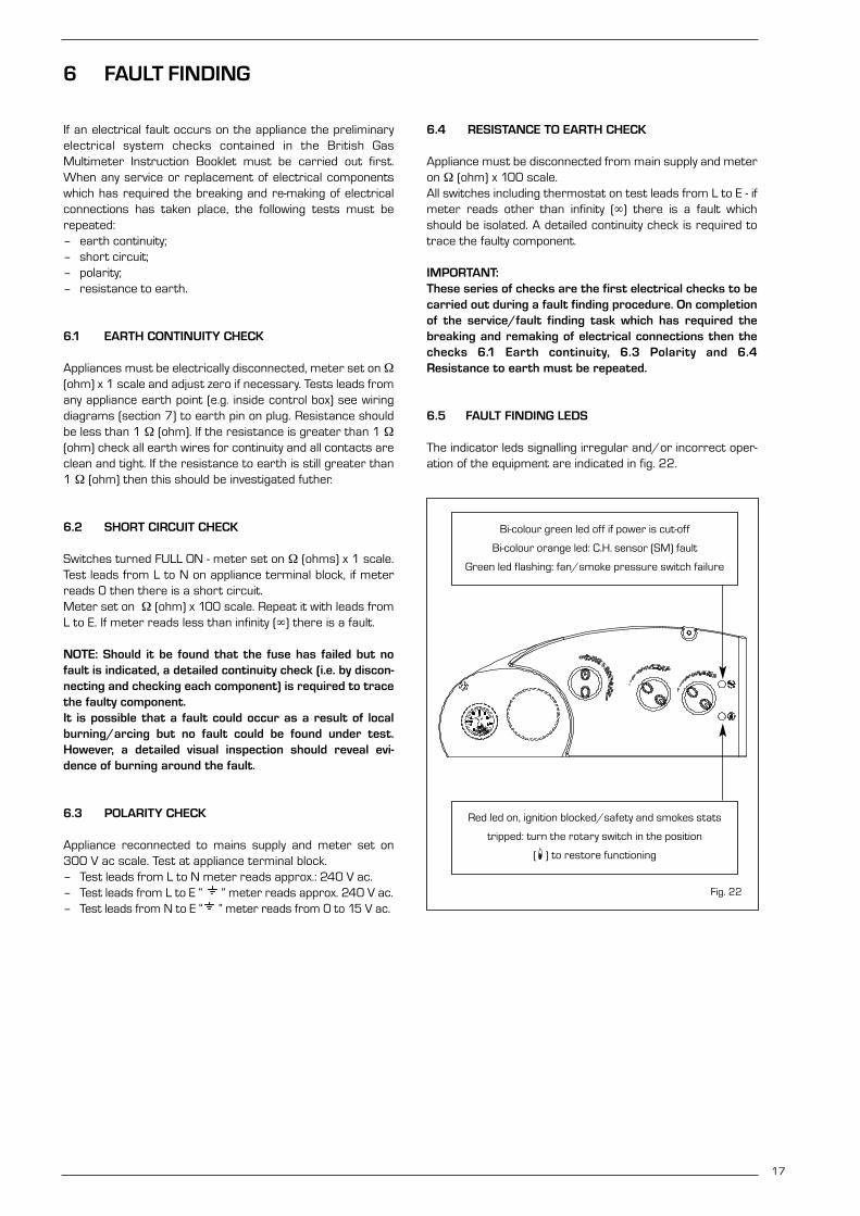
17
If an electrical fault occurs on the appliance the preliminaryelectrical system checks contained in the British GasMultimeter Instruction Booklet must be carried out first.When any service or replacement of electrical componentswhich has required the breaking and re-making of electricalconnections has taken place, the following tests must berepeated:– earth continuity;– short circuit;– polarity;– resistance to earth.
6.1 EARTH CONTINUITY CHECK
Appliances must be electrically disconnected, meter set on Ω(ohm) x 1 scale and adjust zero if necessary. Tests leads fromany appliance earth point (e.g. inside control box) see wiringdiagrams (section 7) to earth pin on plug. Resistance shouldbe less than 1 Ω (ohm). If the resistance is greater than 1 Ω(ohm) check all earth wires for continuity and all contacts areclean and tight. If the resistance to earth is still greater than1 Ω (ohm) then this should be investigated futher.
6.2 SHORT CIRCUIT CHECK
Switches turned FULL ON - meter set on Ω (ohms) x 1 scale.Test leads from L to N on appliance terminal block, if meterreads 0 then there is a short circuit.Meter set on Ω (ohm) x 100 scale. Repeat it with leads fromL to E. If meter reads less than infinity (∞) there is a fault.
NOTE: Should it be found that the fuse has failed but nofault is indicated, a detailed continuity check (i.e. by discon-necting and checking each component) is required to tracethe faulty component.It is possible that a fault could occur as a result of localburning/arcing but no fault could be found under test.However, a detailed visual inspection should reveal evi-dence of burning around the fault.
6.3 POLARITY CHECK
Appliance reconnected to mains supply and meter set on300 V ac scale. Test at appliance terminal block.– Test leads from L to N meter reads approx.: 240 V ac.– Test leads from L to E “ ” meter reads approx. 240 V ac.– Test leads from N to E “ ” meter reads from 0 to 15 V ac.
6.4 RESISTANCE TO EARTH CHECK
Appliance must be disconnected from main supply and meteron Ω (ohm) x 100 scale. All switches including thermostat on test leads from L to E - ifmeter reads other than infinity (∞) there is a fault whichshould be isolated. A detailed continuity check is required totrace the faulty component.
IMPORTANT: These series of checks are the first electrical checks to becarried out during a fault finding procedure. On completionof the service/fault finding task which has required thebreaking and remaking of electrical connections then thechecks 6.1 Earth continuity, 6.3 Polarity and 6.4Resistance to earth must be repeated.
6.5 FAULT FINDING LEDS
The indicator leds signalling irregular and/or incorrect oper-ation of the equipment are indicated in fig. 22.
6 FAULT FINDING
Fig. 22
Bi-colour green led off if power is cut-off
Bi-colour orange led: C.H. sensor (SM) fault
Green led flashing: fan/smoke pressure switch failure
Red led on, ignition blocked/safety and smokes stats
tripped: turn the rotary switch in the position
( ) to restore functioning

18
6.6 C.H. MODE - FAULT FINDING
Start from cold Rotary switch set to WINTER position.Room thermostat (if fitted) calling for heat and all D.H.W. taps off.C.H. thermostat set to maximum position.Clock in the on position.
NOTE:After completing fault finding reset the room thermostat (if fitted) to the required setting. If the appliance will not functioncheck the wiring to the clock and if necessary, replace the clock.
Is there power at the external
socket?
Make power
available
Does the pump
start?
After 20 secondsfrom start of the
pump is the greenled flashing?
Is flow waterswitch closed?
Does the fan start?
Is there a spark at the ignition
electrode?
Is fuse at mains plug OK?
Is there power at L and N terminals?
Is the greenled on?
Check flowwater switch
Smoke fault.Check smoke pres-
sure switch andhis connection
After 20 secondsfrom start of thefan, is the green
led flashing?
Replace fuseon the PCB
Replace fuse inmains plug
Check wire connections to L and N terminals
Is the clock in the correct band time?
Check the time clock: does
his contacts open and closewhen the clock
turns?
Is there 230V ACavailable at the fan terminals?
Replace the PCB Check: gapbetween the
electrode andburner, conditionsof the electrode
and ignitiontransformer.Does it spark
now?
Turn the clock in the right
position
Close room thermostat
contact
Replace the fan
Is there voltageavailable
to the pump?
Replace the clock
Check pump connection
Is pump shaft free to rotate?
Replace the pump
Make it free torotate
Has the PCB ignition
locked-out after 10 seconds
without flame at the burner?
Has the PCB ignition
locked-out after 10 seconds with flame
at the burnerbefore lock?
Check: gapbetween the
electrode andburner, conditionsof the electrode
and ignitiontransformer.Does it now
detect the flame?
Can the burner pressure be
reduced by theC.H. adjuster?
Does the burner pressure reduce
as the temperaturerises towards max.?
Check:
1) C.H. thermistor
2) PCB controlboard
After two minutes(safety time +
C.H. delay time),is the burner
pressure set tothe maximum? Is there a
voltage at themodulator?
Does the boilerswitch off before
achieving the tem-perature?
Is the gasavailable?
Open thegas cock
Is L and Npolarity righton the plug?
Replace themodulator
Replace the PCB
Is the safety thermostat OK?
Replace thesafety
thermostatTurn the plug
Replace theC.H. thermistor
Is there voltage availableto the gas valve?
Replace thegas valve
Set properly the connection
Boiler issatisfactory
Yes
No
Is the room thermostat
contact closed?
Yes
No
Yes
No
Yes
No
No
Yes
No
Yes
No
Yes
Yes
Yes
YesNo
Yes
No
Yes
Yes
Yes
Yes
Yes
Yes No Yes
No
No
No
No
No
No Yes Yes Yes Yes No
Yes
Yes
No
No
No
No
Yes
Yes
Yes
No
Yes
No
No Yes
No
No
No
No

19
6.7 D.H.W. MODE - FAULT FINDING
Start from cold - rotary switch set to SUMMER position, D.H.W. thermostat set to maximum, and all D.H.W. taps OFF.
Is there power at the external
socket?
Make power
available
Does the pump
start?
Does the fan start?
Is there a spark at the ignition
electrode?
Is fuse at mains plug OK?
Replacefuse in
mains plug
Replace fuse onthe PCB
Is the greenled on?
After 20 secondsfrom start of the
pump is the greenled flashing?
Smoke fault.Check smoke pres-
sure switch andhis connection
After 20 secondsfrom start of thefan, is the green
led flashing?
Make it free to rotate
Is there power at L and N terminals?
Check wire connections to L and N terminals
Is there voltage available
at the pump?
Is flow waterswitch closed?
Check flowwater switch
Check: gapbetween the
electrode andburner, conditionsor the electrode
and ignitiontransformer.Does it spark
now?
Is pump shaft free to rotate?
Open any D.H.W. tap to give flow 2.8 l/min. Can you
get the desired flow at the
D.H.W. taps?
Are microswitches of divertor valve
operated?
Check pump connection
Is there 230V acavailable at the fan
terminals?Replace the PCB
Replace the pump
Replace thedivertor valve
Replace the fan
Clean or replacefilter at inlet ofhydraulic group
Has the PCB ignition
locked-out after 10 seconds
without flame at the burner?
Has the PCB ignition
locked-out after10 seconds with flame
at the burnerbefore lock?
Is the gas available?
Open the gas cock
Is the safety thermostat OK?
Replace thesafety thermostat
Is there voltageavailable to
the gas valve?
Set properly the connection
Replace thegas valve
No Yes YesYes
Yes
Yes
Yes
No
No No
No
Yes
No
Yes
Yes
No
Yes
No
No
Yes
No No No
No
Yes
Yes
No
Yes
No
No No
Yes
Yes
No
Yes
Yes
Yes
No
No
No
Yes
Check: gapbetween the
electrode andburner, conditionsof the electrode
and ignitiontransformer.Does it now
detect the flame?
Can the burner pressure be
reduced by theD.H.W. adjuster?
Does the burner pressure reduce
as the temperaturerises towards max.?
Check:
1) C.H. thermistor
2) PCB controlboard
Is the burnerpressure set tothe maximum?
Is therevoltage at themodulator?
Replace theC.H. thermistor
Does the boilerswitch off before
achieving the tem-perature?
Is L and Npolarity righton the plug?
Replace themodulator
Replace the PCB
Turn the plug
Boiler issatisfactory
Yes
Yes Yes Yes Yes No
Yes
Yes
No
No
No
No
Yes
No
No No

20
7 INTERNAL WIRING DIAGRAM AND VIEW
7.1 FUNCTIONAL FLOW WIRING DIAGRAM
KEYL PhaseN NeutralEV1-2 Gas valve coilEAR Ignition/detection electrodeTS 100°C safety thermostatOP Time clockPF Air pressure switchV FanPI Circulating pump
VP Divertor valveC Rotary switch TA Room thermostatFL Flow water switchM ModulatorSM C.H. sensorF1 Fuse (1.6 AT)TR Transformer 230/24VTRA Ignition transformer
NOTE: The room thermostat must be connected to the terminals 10-11of the “TA” connector after having removed the link.
Fig. 23

21
6
12
11
10
9
8
7
5
4
3
2
1
13
14
7.2 INTERNAL VIEW
KEY1 Control panel2 Ignition transformer3 Combustion chamber4 Fan5 Combustion analysis intakes6 Negative pressure intake7 Positive pressure intake
8 Smoke pressure switch9 C.H. sensor (SM)
10 Main exchanger11 100°C safety stat12 Gas valve13 Flow water switch14 Divertor valve
Fig. 24

Before commencing any service operation, ISOLATE themains electrical supply, and TURN OFF the gas supply at themain service cock. It is the law that any service work must becarried out by registered personnel (C.O.R.G.I.).
8.1 HEAT EXCHANGER
– Remove the fan as described in section 8.3.– Disconnect the pressure sensing pipe from the flue box,
lift the collector hood assembly, tilt forwards, and removethe hood.
– Isolate the C.H. flow and return valves.– Drain the heat exchanger using the drain cock (at the bot-
tom RHS of the appliance)– Unclip the heat exchanger securing clips and unscrew
completely the expansion vessel nut.– Disconnect the pipes from the exchanger and lift out the
heat exchanger.– Re-assemble in reverse order, ensuring that the heat
exchanger seals and clips are correctly located and thatthe pressure sensing pipe is correctly re-fitted. The fanpolarity is not important except the earth conductor (G/Ywhich is marked on the appliance).
– Refill, and re-commission the system as described in sec-tion 4.
8.2 COMBUSTION CHAMBER INSULATION
The design of this appliance is such that the rear and sideinsulation should not require replacement unless mechanical-ly damaged.IMPORTANT: When handling insulation panels, take care toavoid producing or inhaling dust particles. When removingold or damaged insulation panels, dampen with water tominimise dust.To replace the insulation front panel, proceed as follows:– remove the combust ion chamber front panel as
described in section 5.1;– replace the front insulation panel and glue it into position
on the front panel using the glue supplied. Re-assemble inreverse order.
Should the rear or side panels become damaged, replacethem as follows.– remove the heat exchanger as described in section 8.1;– remove the side insulation panels followed by the rear
panel;– re-assemble in reverse order, refill, and recommission the
system as described in section 4.
8.3 FAN ASSEMBLY
– Remove the casing front panel and sealed chamber frontpanel as described in section 5.1.
– Disconnect the electrical connections and the pressuresensing pipes to the fan. Note the position of the earthconductor.
– Unscrew the three screws securing the fan.– Drop and tilt the fan forwards and remove in a down-
wards direction.– Re-assemble in reverse order. Ensure that the earth con-
nection is correctly refitted. Note that the polarity (Lineand Neutral) is immaterial.
8.4 MAIN BURNER
– Remove the main burner by following section 5.1.– Transfer the ignition electrode onto the new burner
assembly.– Re-assemble in reverse order. Check the electrode gaps
(fig. 24) and test for gas soundness. – Re-commission the appliance as described in section 4.
8.5 IGNITION/DETECTION ELECTRODE
– Remove the casing front panel and sealed chamber frontpanel as described in section 5.1.
– Unscrew the single screw securing the electrode in posi-tion, and release the electrode from the burner.
– Remove the electrode and disconnect its cable from theignition transformer.
– Replace the electrode and re-assemble in reverse order.
8.6 GAS VALVE
– Remove the casing front panel as described in section 5.1.– Disconnect the two leads from the modulating solenoid
and disconnect the valve connector (one screw).– Unscrew the nut between the inlet pipe and the valve.– Unscrew the burner manifold nut underneath the
sealed chamber, and withdraw the gas valve completewith outlet pipe.
– Transfer the outlet pipe onto the new gas valve, using anew gasket (supplied with the valve).
– Fit the new gas valve assembly into the appliance usingthe other new gasket supplied on the valve inlet, and re-assemble in reverse order.
– Re-light the appliance, check for gas soundness, and re-commission in accordance with section 4.
In addition it will be necessary to set the D.H.W. and C.H.heat inputs, with reference to fig. 25, as follows:Note that it is necessary to set the MAXIMUM PRESSURE FIRST.– Connect a pressure gauge to the burner pressure
test point.– Remove the sealing cap of the proportioning unit (C) by
rotating it ⁄ turn anticlockwise.– Adjust DHW potentiometer to maximum, then fully open
any DHW tap to light the boiler.– Using a 10 mm spanner, turn nut (B) to attain the maxi-
22
8 REPLACEMENT OF PARTS
– 0
.54
+ 0
.5 IGNITION/DETECTIONELECTRODE
Fig. 25

mum pressure in Table 3. Turn the nut clockwise to increase or anti-clockwise todecrease the burner pressure.
– Turn the main selector switch on and off a few times (withthe hot tap still open) and check that the pressure returnsto the correct (set) maximum value (as in Table 3).
– Set the minimum burner pressure by first isolating theelectricity supply and disconnecting one of the modulat-ing solenoid leads, then restore the electricity supply andfully open a DHW tap to light the appliance at minimumgas rate.
– Set the minimum pressure with reference to Tables 3 byholding nut (B) in position with a 10 mm spanner and rotat-ing the plastic screw (A) with a screwdriver until the correctpressure is obtained. Turn the screw clockwise to increasethe pressure or anti-clockwise to decrease it. It is essentialthat the max pressure has been set prior to adjusting theminimum pressure. Check that the minimum pressure iscorrectly set by turning on and off the D.H.W. inlet valve sev-eral times and ensuring that the pressure returns to thatpreviously adjusted;
– Isolate the power supply, re-connect the modulation lead,restore the power and re-check the maximum pressure,then re-fit the plastic cover (1).
– Reduce the D.H.W. draw off rate to the minimum nec-essary to maintain the burner alight by carefully adjustingthe D.H.W. Inlet valve and check that the burner pressuredecreases in response to D.H.W. temperature rise. Fullyopen the inlet valve;
– Close the D.H.W. tap and ensure that the burner is extin-guished and the pump stops.
– Adjust the Central Heating maximum pressure asdescribed in section 4.3, then complete the re-commis-sioning as described in 4.4 and 4.5.
8.7 AIR PRESSURE SWITCH
– Remove the casing front panel and sealed chamber frontpanel as described in section 5.1.
– Disconnect the pressure sensing pipe from the switch.– Remove the switch (two screws) and fit the new one.– Transfer the electrical connections one at a time (to ensure
that they are not incorrectly re-fitted) to the new switch.
– Re-assemble in reverse order referring to the wiring dia-grams (section 7) if necessary. Ensure that the pressuresensing lead is correctly connected to the low pressureconnection on the pressure switch (marked P2).
8.8 OVERHEAT THERMOSTAT
The overheat thermostat is situated on the flow pipe, belowthe sealed chamber (11 fig. 24).– Remove the casing front panel as described in section 5.1.– Disconnect the two overheat thermostat wires.– Unscrew the two limit thermostat fixing screws and
remove the thermostat.– Replace the thermostat and spread heat sink compound
(supplied) over the base of the new one.– Re-assemble in reverse order. (Polarity is immaterial).
8.9 THERMISTOR
The thermistor is placed over the main exchanger. – Remove the casing front panel as described in section 5.1.– Isolate the C.H. flow and return valves (19 - 18 fig. 2),
and drain the appliance through the drain plug (13fig. 2).
– Pull off the electric connection, and unscrew the thermis-tor from the exchanger.
– Replace the thermistor and re-assemble in reverse order.Table 9 shows the resistance values (Ω) that are obtainedon the sensor as the temperature varies.
8.10 DRIVER PCB
– Remove the casing front panel as described in section 5.1.– Open the control panel protecting cover by removing the
four fixing screw.– Pull off the potentiometer knobs.– Release the PCB (four screws), transfer all connections
onto the new PCB, and re-assemble in reverse order.– Re-set the CH burner pressure as described in section 4.3.
8.11 PUMP MOTOR
– Remove the casing front panel as described in section 5.1.– Unplug the electrical connection plug.– Isolate the C.H. flow and return valves (19 - 18 fig. 2), and
drain the appliance through the drain plug (13 fig 2).– Unscrew the four fixing screws on the motor.– Replace the pump motor and re-assemble in reverse
order. If the new pump is fitted with a speed adjuster,ensure that the speed is set to maximum.
23
Temperature (°C) Resistance (Ω)
20 12,09030 8,31340 5,82850 4,16160 3,02170 2,22980 1,669
TABLE 9
KEYA Plastic screwB NutC Sealing cap Fig. 26
– Refill and commission the system as described in section 4.1.
8.12 D.H.W. HEAT EXCHANGER
– Remove the casing front panel as described in section 5.1.– Isolate the C.H. flow and return valves, and the D.H.W. iso-
lation valve (19 - 18 - 20 fig. 2).– Drain the appliance through the drain plug (13 fig 2).– Drain the D.H.W. circuit by opening any D.H.W. tap below
the level of the boiler.– Lift off the microswitch assembly.– Remove the three screws fixing the D.H.W. heat exchang-
er and remove the heat exchanger.– Fit new heat exchanger and re-assemble in reverse order
using the new gaskets supplied with the heat exchanger.– Refill and re-commission the system as described in sec-
tion 4.1.
8.13 DIVERTOR VALVE - COMPLETE
– Remove the casing front panel as described in section 5.1.– Isolate the C.H. flow and return valves, and the D.H.W. iso-
lation valve (19 - 18 - 20 fig. 2).– Drain the appliance through the drain plug (13 fig 2)– Drain the D.H.W. circuit by opening any D.H.W. tap below
the level of the boiler.– Lift off the microswitch assembly.– Remove the three screws fixing the D.H.W. heat exchang-
er and remove the heat exchanger.– Pull out the divertor valve circlip and remove the valve.– Transfer the electrical connections onto the new valve. If
necessary. refer to the wiring diagrams in section 7.– Re-assemble in reverse order, using the new gaskets sup-
plied with the valve.– Refill and re-commission the system as described in section 4.1.
8.14 DIVERTOR VALVE - MICROSWITCH ASSEMBLY
– Remove the casing front panel as described in section 5.1.– Remove the two screws pivot the control box downwards.– Lift off the microswitch assembly.– Transfer the electr ical connections onto the new
microswitch assembly. If necessary refer to the wiring dia-grams in section 7.
– Re-assemble in reverse order.
8.15 C.H. EXPANSION VESSEL
In the unlikely event of failure of the expansion vesseldiaphragm it is acceptable to leave the vessel in positionand to fit a replacement vessel (of similar or greater capac-ity) external to the appliance but as close as possible to theC.H. return. Alternatively the vessel can be replaced as follows. Note replacement is not recommended if a rear flue outletis used or if the clearance above the casing is less than300 mm.– Remove the casing front panel as described in section 5.1.– Isolate the C.H. flow and return valves (17 - 18 fig. 2), and
drain the appliance through the drain plug (13 fig. 2).– Unscrew the expansion vessel union on the C.H. return
pipe.– If a rear flue outlet is used it is necessary to disengage
the flue and air duct temporarily. Refer to section 3.5.– Remove the adjusting screws on the wall mounting brack-
et thereby allowing the appliance to move slightly for-wards at the top.
– Lift the expansion vessel out of the appliance throughthe top.
– Replace the expansion vessel and re-assemble in reverseorder. Re-pressurise and re-commission the system asdescribed in section 4.1.
8.16 THERMOHYDROMETER
– Remove the casing front panel as described in section 5.1.– Isolate the C.H. flow and return valves (19 - 18 fig. 2).– Drain the appliance through the drain point (13 fig. 2).– Remove the circlip securing the pressure sensor to the
hydraulic group and pull out the sensor.– Remove the fixing spring of the thermometer bulb from
the C.H. flow pipe.– Squeeze the gauge to depress the retaining clips, then
ease the gauge forwards.– Reassemble in reverse order.
Refill and re-commission the system as described in sec-tion 4.1.
8.17 SAFETY VALVE
– Remove the casing front panel as described in section 5.1.– Isolate the C.H. flow and return valves (19 - 18 fig. 2).– Drain the appliance through the drain point (13 fig. 2)– Remove the circlip securing the valve to the hydraulic
group and remove the valve.– Fit the new safety valve and re-assemble in reverse order.
Refill and re-commission the system as described in sec-tion 4.1.
8.18 AUTOMATIC AIR VENT
– Remove the casing front panel as described in section 5.1.– Isolate the C.H. flow and return valves (19 - 18 fig. 2).– Drain the appliance through the drain point (13 fig. 2).– Remove the circlip securing the automatic air vent to the
hydraulic group.– Fit the new automatic air vent and re-assemble in reverse
order. Refill and re-commission the system as describedin section 4.1.
8.19 TIME CLOCK
– Remove the casing front panel as described in section 5.1.– Open the control panel protecting cover by removing the
four fixing screws.– Pull off the electrical connections at the back of the clock.– Remove the two screws securing the plastic frame of the
time clock to the facia panel.– Remove the plastic frame and pull out the time clock.– Re-assemble in reverse order and test the operation of
the new clock.– Set it to the desired settings as described in section 4.3.
24

25
KEY DESCRIPTION NO OFF MAKER’S PT NO
1 Main burner POLIDORO (“80 C”) 1 5190700
1 Main burner POLIDORO (“100 C”) 1 5190750
2 a Main injector NP 130 (“80 C”) 12 6154402
2 b Main injector NP 130 (“100 C”) 14 6154402
2 c Main injector G30 - G31 NP 0.77 (“80 C”) 12 6154410
2 d Main injector G30 - G31 NP 0.78 (“100 C”) 14 6154414
3 Ignition/detection electrode 1 6235929
4 SIT SIGMA 845 gas valve 1 6243810
5 Thermistor 1 6231351
6 Driver PCB 1 6230687
7 Air pressure switch 1 5192100
8 Overheat thermostat 1 6146701
9 a D.H.W. heat exchanger (“80 C”) 1 6281508
9 b D.H.W. heat exchanger (“100 C”) 1 6281522
10 a Heat exchanger (“80 C”) 1 6174230
10 b Heat exchanger (“100 C”) 1 6174231
11 a Fan assembly (“80 C”) 1 6225621
11 b Fan assembly (“100 C”) 1 6225622
12 Rotary switch 1 6260701
13 a Circulating pump motor Myson (“80 C”) 1 6272300
13 b Circulating pump motor Dab (“80 C”) 1 6272301
13 c Circulating pump motor (“100 C”) 1 6272302
14 Divertor valve 1 6281504
15 Safety valve 1 6040201
16 C.H. expansion vessel 6 l (“80 C”) 1 5139120
16 C.H. expansion vessel 8 l (“100 C”) 1 5139130
17 Time clock 1 6197709
9 SHORT LIST OF PARTS
1
3
42
67
8
9
11
12
13
14 15 16 17
10
5
Fig. 27

26

THE FAMILY RANGE OF COMBINATION BOILERS
Join us at our training centre for installation
and technical courses on our range of boilers.
We provide free of charge:
installation, fault finding and
in-depth technical training courses.
FREE LUNCH
Certificate on completion of the course.
Please fill in the form below for more details.
Combination Boilers
Name: . . . . . . . . . . . . . . . . . . . . . . . . . . . . . . . . . . . . . . . . . . . . . . . . . . . . . . . . . . . . . . . . . . .
Address: . . . . . . . . . . . . . . . . . . . . . . . . . . . . . . . . . . . . . . . . . . . . . . . . . . . . . . . . . . . . . . . . .
. . . . . . . . . . . . . . . . . . . . . . . . . . . . . . . . . . . . . . . . . . . . . . . . . . . . . . . . . . . . . . . . . . . . . . . . . .
. . . . . . . . . . . . . . . . . . . . . . . . . . . . . . . . . . . . . . . . . . . . . . . . . . . . . . . . . . . . . . . . . . . . . . . . . .
Postcode: . . . . . . . . . . . . . . . . . . . . . . . . . .Tel No. . . . . . . . . . . . . . . . . . . . . . . . . . . . . . . .
Company: . . . . . . . . . . . . . . . . . . . . . . . . . . . . . . . . . . . . . . . . . . . . . . . . . . . . . . . . . . . . . . . .
Please hand this slip to your local merchant, or return it to:
SIME HEATING products UK ltd
Jubilee Works - Middlecroft Road
Staveley - Chesterfield - Derbyshire S 43 3XN
Tel. 01246/471950 - Fax 01246/281822

Cod
. 6
27
22
51
- D
ocum
enta
tion
Dpt
.
h e a t i n g p ro d u c t s u . k . l t d .Jubilee Works - Middlecroft Road - Staveley - Chesterfield - Derbyshire S 43 3XN
Tel. 01246/471950 - Fax 01246/281822
For service enquiries and boiler faults contact our service company on:
Tel. 01246/470777 - Fax 01246/470094

CO
D.
TYP
ED
ATEPA
GE
Fonderie Sim
e S.p.A
. - Via G
arbo, 27
- 37
04
5 Legnago (V
R) - Tel. +
39
-04
42
-63
1111 - Fax +
39
-04
42
-63
129
2 - w
ww
.sime.it
49
104
102
101
54
44
43
51
45
4
2
5 3 1
19 20
21
1825
98
24
22
23
6 63
1
65 64
81
26
3113
30
3332
1636
29
28
27
9392
34
99
14
71517
811
9495
7596
87
73
85 97
8078
86
7977
76
78
8384
82
72
12
6970
67 68
71
910
9052
4888
45
3757
5340
3839
41
91
38
35
FORMAT.ZIP UK
100
63
42
38
74
104
7066
105106
103
7246
5589
107 50
61
5847
59
56
62
60
38
20
04
4/
52
8FO
RM
AT C
UK
12.0
9.2
00
11
/4
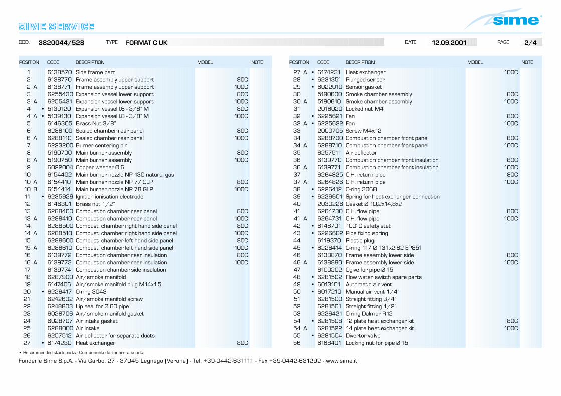
Fonderie Sime S.p.A. - Via Garbo, 27 - 37045 Legnago (Verona) - Tel. +39-0442-631111 - Fax +39-0442-631292 - www.sime.it
POSITION CODE DESCRIPTION MODEL NOTE
COD. TYPE DATE PAGE
• Recommended stock parts - Componenti da tenere a scorta
POSITION CODE DESCRIPTION MODEL NOTE
1 6138570 Side frame part 2 6138770 Frame assembly upper support 80C2 A 6138771 Frame assembly upper support 100C 3 6255430 Expansion vessel lower support 80C3 A 6255431 Expansion vessel lower support 100C 4 • 5139120 Expansion vessel l.6 - 3/8” M 80C4 A • 5139130 Expansion vessel l.8 - 3/8” M 100C 5 6146305 Brass Nut 3/8”6 6288100 Sealed chamber rear panel 80C6 A 6288110 Sealed chamber rear panel 100C 7 6223200 Burner centering pin8 5190700 Main burner assembly 80C8 A 5190750 Main burner assembly 100C 9 6022004 Copper washer Ø 6
10 6154402 Main burner nozzle NP 130 natural gas 10 A 6154410 Main burner nozzle NP 77 GLP 80C10 B 6154414 Main burner nozzle NP 78 GLP 100C 11 • 6235929 Ignition-ionisation electrode 12 6146301 Brass nut 1/2”13 6288400 Combustion chamber rear panel 80C13 A 6288410 Combustion chamber rear panel 100C 14 6288500 Combust. chamber right hand side panel 80C14 A 6288510 Combust. chamber right hand side panel 100C 15 6288600 Combust. chamber left hand side panel 80C15 A 6288610 Combust. chamber left hand side panel 100C 16 6139772 Combustion chamber rear insulation 80C16 A 6139773 Combustion chamber rear insulation 100C 17 6139774 Combustion chamber side insulation18 6287900 Air/smoke manifold19 6147406 Air/smoke manifold plug M14x1.5 20 • 6226417 O-ring 3043 21 6242602 Air/smoke manifold screw22 6248803 Lip seal for Ø 60 pipe23 6028706 Air/smoke manifold gasket 24 6028707 Air intake gasket 25 6288000 Air intake26 6257512 Air deflector for separate ducts27 • 6174230 Heat exchanger 80C
27 A • 6174231 Heat exchanger 100C 28 • 6231351 Plunged sensor29 • 6022010 Sensor gasket 30 5190600 Smoke chamber assembly 80C30 A 5190610 Smoke chamber assembly 100C 31 2016020 Locked nut M4 32 • 6225621 Fan 80C32 A • 6225622 Fan 100C 33 2000705 Screw M4x12 34 6288700 Combustion chamber front panel 80C34 A 6288710 Combustion chamber front panel 100C 35 6257511 Air deflector 36 6139770 Combustion chamber front insulation 80C36 A 6139771 Combustion chamber front insulation 100C 37 6264825 C.H. return pipe 80C37 A 6264826 C.H. return pipe 100C 38 • 6226412 O-ring 3068 39 • 6226601 Spring for heat exchanger connection40 2030226 Gasket Ø 10,2x14,8x241 6264730 C.H. flow pipe 80C41 A 6264731 C.H. flow pipe 100C 42 • 6146701 100°C safety stat 43 • 6226602 Pipe fixing spring44 6119370 Plastic plug45 • 6226414 O-ring 117 Ø 13,1x2,62 EP85146 6138870 Frame assembly lower side 80C46 A 6138880 Frame assembly lower side 100C 47 6100202 Ogive for pipe Ø 15 48 • 6281502 Flow water switch spare parts 49 • 6013101 Automatic air vent50 • 6017210 Manual air vent 1/4”51 6281500 Straight fitting 3/4” 52 6281501 Straight fitting 1/2” 53 6226421 O-ring Dalmar R12 54 • 6281508 12 plate heat exchanger kit 80C54 A 6281522 14 plate heat exchanger kit 100C 55 • 6281504 Divertor valve56 6168401 Locking nut for pipe Ø 15
3820044/528 FORMAT C UK 12.09.2001 2/4

Fonderie Sime S.p.A. - Via Garbo, 27 - 37045 Legnago (Verona) - Tel. +39-0442-631111 - Fax +39-0442-631292 - www.sime.it
POSITION CODE DESCRIPTION MODEL NOTE
COD. TYPE DATE PAGE
• Recommended stock parts - Componenti da tenere a scorta
POSITION CODE DESCRIPTION MODEL NOTE
57 6226607 Pipe fixing spring58 • 6272300 Circulating pump CP 53 Myson motor 80C58 A • 6272301 Circulating pump VA 55 Dab motor 80C58 B • 6272302 Circulating pump CP 63 Myson motor 100C 59 • 6226416 O-ring Ø 75,87x2,62 for Myson 59 A • 6028705 Gasket EP709 for Dab 80C60 6281520 Flange + OR for Myson pump60 A 6281521 Flange + OR for Dab pump 80C61 2000201 Screw M5x40 62 • 6040201 Pressure relief valve 63 6288200 Sealed chamber side panel 64 • 6280510 3-ways junction 65 • 5192100 Air pressure switch 66 2013304 Fastener for self tapping screw 67 • 6243810 SIT gas valve type 845 SIGMA68 6226856 Gas inlet pipe69 6226945 Pipe connecting gas valve-main burner 70 2030228 Gasket Ø 17x24x271 6146302 Brass nut 3/4”72 2030227 Gasket Ø 12x18x273 6289800 Control panel 74 6273210 Guidelight - 2 ways out 75 6217005 Temperature and pressure gauge76 • 6230687 Main PCB with ignition77 • 6201501 Trimmer spindle Ø 5 78 • 6201505 Trimmer spindle Ø 6 79 • 6260701 Rotary switch 80 2211610 Earth faston81 • 6098304 Ignition transformer82 6289900 Control panel protecting cover83 6290300 Control panel cable cover 84 6290200 Room stat connection cover85 6290100 Knob Ø 40 86 6009585 Control panel bracket 87 6290001 Flap door 80C87 A 6290002 Flap door 100C 88 • 6131401 Microswitch for flowmeter 89 5191900 Divertor valve microswitch + support
90 6226605 Fixing spring 91 2051100 Retaining spring92 6288350 Sealed chamber front panel 80C92 A 6288360 Sealed chamber front panel 100C 93 6001210 Peephole94 6287321 Casing 80C94 A 6287331 Casing 100C 95 • 2013302 Fastener for self tapping screw 96 2004510 Screw 8Px7/8” 97 6112420 Control panel screw 98 6028624 Air diaphragm Ø 87.599 5192200 Gasket for sealed chamber
100 6263905 Fan pressure test point 101 6223351 Venturi 80C101 A 6223352 Venturi 100C 102 • 6197709 Time programmer 103 6142330 Quarter bend 1/2” x 15103 A 6147231 Straight fitting 1/2” Ø 15 LPG104 6177505 Ball cock 3/4” x 22 104 A 6245000 Ball cock 3/4” LPG105 6177506 Ball cock 1/2” x 15 105 A 6245001 Ball cock 1/2” LPG106 6177504 Gas cock 1/2” x 1/2”106 A 6063601 Gas cock 1/2” LPG107 6157602 Pressure relief valve drain pipe
5191110 Complete control panel6127210 Main cable L=2000 6245335 845 Sigma gas valve connector 6278671 6 pole LUMBERG cable connector6278673 6 pole Stocko cable connector 6278674 8 pole STOCKO cable connector 6278675 5 pole STOCKO cable connector 6278688 10 pole LUMBERG cable connector
• 5144712 Conversion kit to LPG 80C• 5144713 Conversion kit to LPG 100C • 6233506 Fuse T1,6A 250V • 6281506 O-ring kit for hydraulic group
3820044/528 FORMAT C UK 12.09.2001 3/4
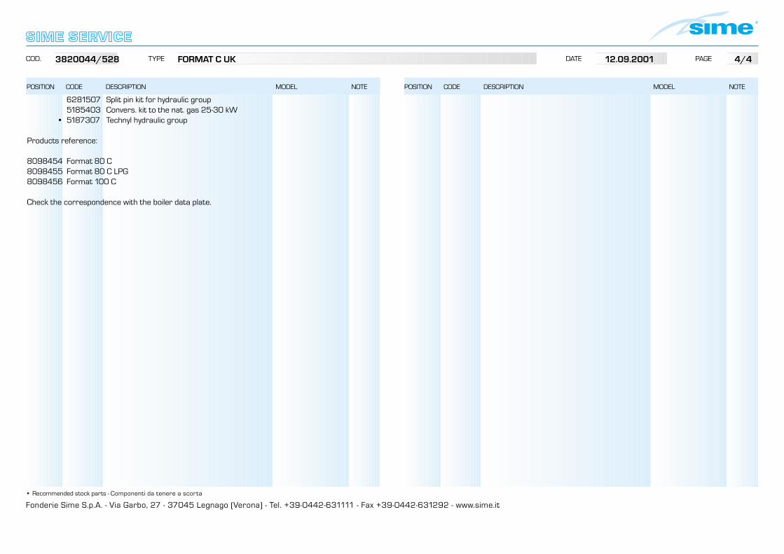
Fonderie Sime S.p.A. - Via Garbo, 27 - 37045 Legnago (Verona) - Tel. +39-0442-631111 - Fax +39-0442-631292 - www.sime.it
POSITION CODE DESCRIPTION MODEL NOTE
COD. TYPE DATE PAGE
• Recommended stock parts - Componenti da tenere a scorta
POSITION CODE DESCRIPTION MODEL NOTE
6281507 Split pin kit for hydraulic group 5185403 Convers. kit to the nat. gas 25-30 kW
• 5187307 Technyl hydraulic group
Products reference:
8098454 Format 80 C8098455 Format 80 C LPG8098456 Format 100 C
Check the correspondence with the boiler data plate.
3820044/528 FORMAT C UK 12.09.2001 4/4