Embed Size (px)
Citation preview
Simmons, Patty
From:
Sent:
To : Simmons, Patty
cc: Subject:
Attachments: EG&G Patent Docs.doc
D a I e J C I afl in [ D a I e. C I a fl i n @ i n I. g ov]
Thursday, December 07,2006 8:43 AM
Claflin, Dale; Flynn, Vesta; Ponce, Linda
Re: EG&G Idaho Geothermal Reports
Patty,
The 13 reports listed are all OK for unrestricted release. Please remove (cover up) the patent caution wording, as well as any other statements concerning restricted distribution. We don't have a concern with the "Internal Technical Report" words, but if you feel it would eliminate confusion by removing that term, please do so. Let me know if you need anything else.
Dale Claflin Idaho National Laboratory 208-526-1 199 (voice) 208-526-8092 (fax) [email protected]
"Simmons, Patty" <[email protected]>
12/06/2006 1234 PM
cc "Ponce, Linda" [email protected]>, "Flynn, Vesta" <[email protected]>
Subject EG&G Idaho Geothermal Reports
Dale,
OSTl has been working on a project for the last year or so to collect geothermal documents. At the STlP meeting in April, I sent out a plea to the DOE labs to identify and send to OSTI any geothermal documents that we did not already have in our database. I have a problem with a group of reports from EG&G Idaho. I am not sure you are the person correct person to ask for help on this issue. If not, maybe you can direct me to the responsible individual.
Attached is a list of documents that were sent to OSTl as part of that special geothermal project. All of the documents in this list have a patent caution as well as 'Internal Technical Report' stamped on the front of the report. The date on each of the documents is well past the sunset date for patentable material. If there is no other reason for control, I would like permission to cover up the patent caution and release each as unlimited. Would we also need to cover 'Internal Technical Report'?
If you need me to, I will be happy to fax you a copy of the covers of the reports.
Please let me know if you can help me out with this problem, or advise if I should communicate with someone
12/7/2006
rage L or L
else - and who .
Thanks ahead for your help, Patty
fjz~tty S i m m o n s
U S . DOE Office of Scientific and Techmcal Information qin-ini.oOsp@?bst_I.sov 865-576- 1290
12/7/2006

DISCLAIMER
This report was prepared as an account of work sponsored by an agency of the United States Government. Neither the United States Government nor any agency Thereof, nor any of their employees, makes any warranty, express or implied, or assumes any legal liability or responsibility for the accuracy, completeness, or usefulness of any information, apparatus, product, or process disclosed, or represents that its use would not infringe privately owned rights. Reference herein to any specific commercial product, process, or service by trade name, trademark, manufacturer, or otherwise does not necessarily constitute or imply its endorsement, recommendation, or favoring by the United States Government or any agency thereof. The views and opinions of authors expressed herein do not necessarily state or reflect those of the United States Government or any agency thereof.

DISCLAIMER Portions of this document may be illegible in electronic image products. Images are produced from the best available original document.
D i s t r i b u t i o n
ii
C. J . Bl iem 0. J . Dernuth J . A. Hoffman R. J . Kochan M. M. Laugh l i n ( 3 ) K. H. L i e b e l t J . L. L iebentha l G. L. Mines C. A. Moore N. E. Pace J . F. Whitbeck D. J . Wiggins
I
SUMMARY
T h i s r e p o r t presents t h e thermal s p e c i f i c a t i o n s f o r t h r e e heat ex-
changers (preheater , b o i l e r and condenser) t o he used i n a 60 kW p ro to type
power p l a n t i n s t a l l e d a t t h e R a f t R ive r geothermal f a c i l i t y .
t y p e p l a n t i s unique i n t h a t i t w i l l u t i l i z e a work ing f l u i d o f 90%
propane - 10% isopentane (by weight ) o p e r a t i n g a t s u p e r - c r i t i c a l pressures
i n a b i n a r y geothermal c y c l e t o e x t r a c t energy f rom a 28OoF geothermal
resource. Studies have shown t h a t t h i s s u p e r ' - c r i t i c a l c y c l e can p r o v i d e a
n e t performance about 20% h igher than t h a t o f t h e optimum d u a l - b o i l i n g
isobutane c y c l e c u r r e n t l y designed f o r t h e 5 MbJ R a f t R i v e r p i l o t p l a n t .
Th i s p r o t o -
. .
iii
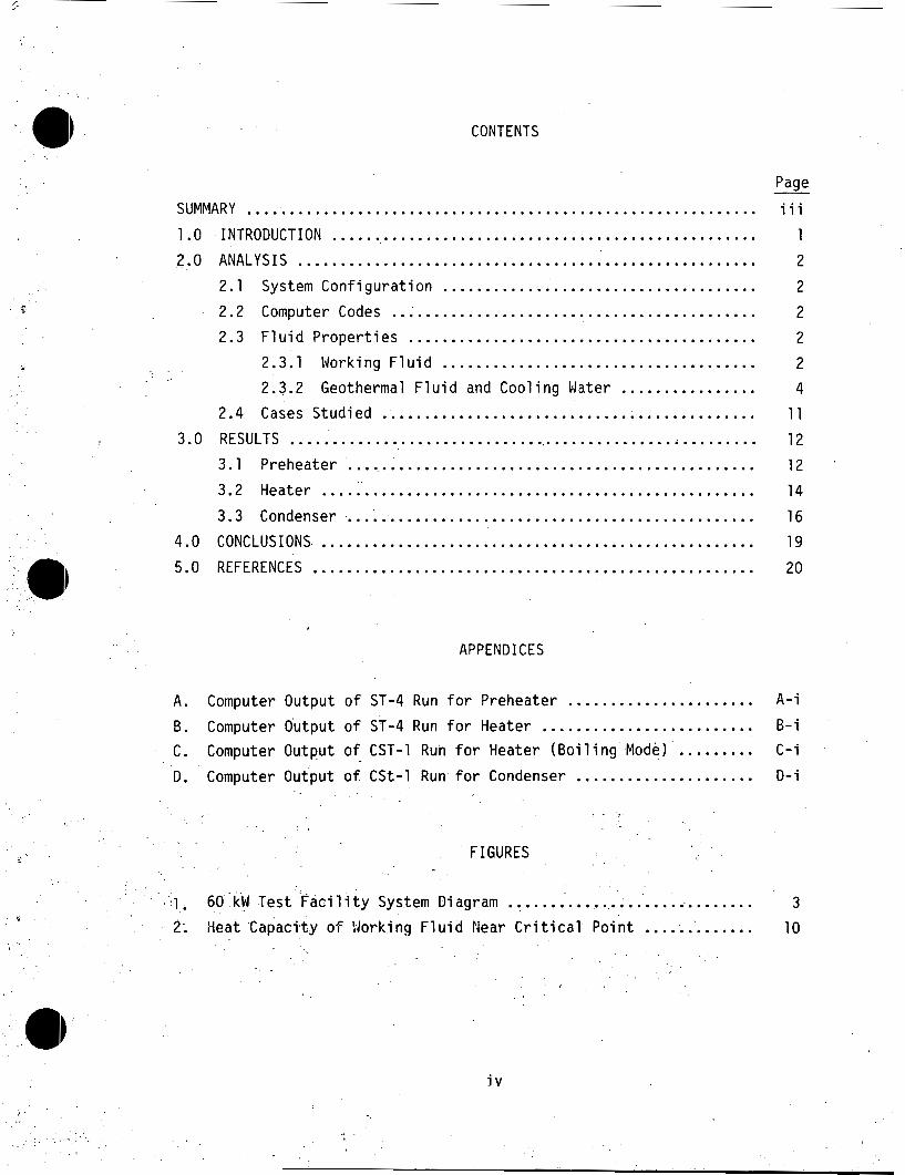
CONTENTS
Page - SUMMARY ............................................................ iii
1.0 INTRODUCTION .................................................. 1
2 2.0 ANALYSIS ...................................................... 2.1 System C o n f i g u r a t i o n ...................................... 2
2.2 Computer Codes .. ;.... .................................... 2.3 F l u i d P roper t i es 2
2.3.1 Working F l u i d 2 1. I ......................................
2.3.2 Geothermal F l u i d and Coo l ing W.ster ................
2 .........................................
4 2.4 Cases Stud ied ............................................ 11
3.0 RESULTS ........................................................ 12
3.1 Preheater ................................................. 12
3.2 Heater ................................................... 14
3.3 Condenser ................................................. 16
4.0 CONCLUSIONS. ................................................... 19
5.0 REFERENCES .................................................... 20
A. B. c . D.
- .
Computer Output o f ST-4 Run Computer Output o f CST-1 Run Computer Output o f CSt-1 Run
APPENDICES
Computer Output o f ST-4 Run f o r Preheater ...................... o r Heater ......................... f o r Heater (Boi 1 i n g Mode) ......... f o r Condenser .....................
. .
FIGURES
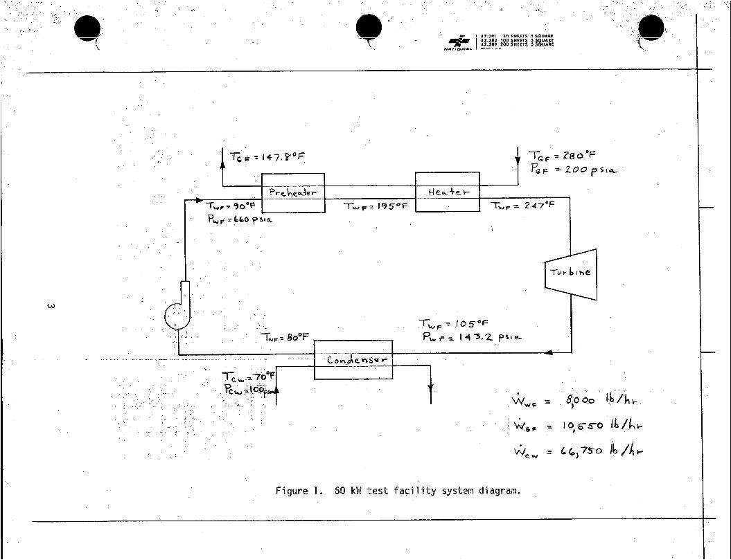
60 kW Test F a c i l i t y System Diagram ............................. Heat Capaci ty o f ! lork ing F l u i d Near C r i t i c a l P o i n t ..............
A - i
B - i C - i
D- i
3
10
i v
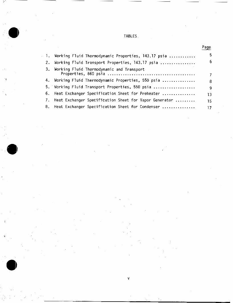
TABLES
1 . 2 . 3 . 4 . 5 . 6 . 7 . 8 .
Working F l u i d Thermodynamic Proper t ies . 143.17 p s i a ............ Nork ing F l u i d Transpor t Proper t ies . 143.17 p s i a ................ Worki ng F1 u i d Thermodynamic and Transpor t
P roper t i es . 660 p s i a ........................................ Worki ng F1 u i d Thermodynamic P roper t i es . 550 p s i a ............... Working F l u i d Transpor t Proper t ies . 550 p s i a ................... Heat Exchanger S p e c i f i c a t i o n Sheet f o r Preheater ............... Heat Exchanger Spec i f i ' ca t i on Sheet f o r Vapor Generator ......... Heat Exchanger S p e c i f i c a t i o n Sheet f o r Condenser ...............
Page
5 6
7
8 9
13
15
17
V
1.0 INTRODUCTION
This report presents the details of the analysis used t o size the pre- heater, heater and condenser for the 60 kW prototype plant t o be installed a t the Raft River geothermal t e s t fac i l i ty . These units will be used t o study a thermodynamic cycle i n which a mixture of hydrocarbons (90% pro- pane - 10% isopentane) are t o be used as the w o r k i n g f luid t o extract energy from a 28OoF geothermal resource. mainta ned a t supercritical pressures i n the heater units. Studies have shown t h a t t h i s cycle will provide a net power increase of 20% over the dual-boiling isobutane cycle designed for the '5 MW Raft River t e s t fac i l i ty .
The working fluid will be
1
I n order t o fully ut i l ize the low temperature resource and resultant close temperature approaches in the heat exchangers (pinch points were selected t o be as low as 10°F), pure countercurrent flow heat exchangers (E-she1 Is) were selected. dynamic efficiency i n the heat exchange process. made t o minimize the effects of differential condensation (separation of the heavier component as i t begins t o condense) by uti l izing in-tube condensation in a vertical configuration. Differential condensation results in a decrease in the already small mean temperature difference in the condenser with a corresponding severe loss in overall cycle efficiency. The study of this effect will be an important result of the prototype t e s t program.
This configuration provides the highest thermo- I n a d d i t i o n , an effort was
2.1 System Con f igu ra t i on
The heat exchangers u
2.0
d t o h
ANALYSIS
a t t h e work ing f l u i d t o i t s f i n a l
teernperature o f about 247OF w i l l c o n s i s t o f a p rcheater and a heater , bo th
ope ra t i ng a t s u p e r c r i t i c a l pressures o f about 660 p s i a .
w i l l heat 0000 l b / h r o f 9 l0F work ing f l u i d t o 195'F, and t h e heater w i l l r a i s e i t t o 247OF f o r expansion i n t h e t u r b i n e . The coun te rcu r rcn t f l o w
heat source w i l l be 10,550 l b / h r o f 28O0F geothermal f l u i d . A condenser
w i l l use 66,750 l b / h r o f 70°F c o o l i n g water t o desuperheat, condense, and
subcool t h e work ing f l u i d a t 143.1 p i a .
condenser a t 105OF and e x i t s a t 8O0F. p o i n t s were prov ided by t h e Geothernal Branch' and a re shown on the system
diagram o f F igu re 1.
The prcheater
The work ing f l u i d en te rs t h e
The systern des ign and f l u i d s t a t e
2.2 Computer Codes
however ,
2.3 F l u
2.3
The
.The heat exchanger s i z i n g was performed w i t h t h e ST-4 (Mod. 5.2) and CST-1 (Mod. 1.1 ) heat exchanger computer codes. These are p r o p r i e t a r y codes a v a i l a b l e t o EG&G as a member company o f Heat T rans fe r Research, I nc .
(HTRI) and can be used t o des ign and r a t e she l l -and- tube condensers and
b o i l e r s (CST-1) and she1 1-and-tube heat exchangers (ST-4). Due t o t h e
p r o p r i e t a r y na tu re o f t h e codes, program l i s t i n g s cannot be publ ished;
documentation o f i n p u t and ou tpu t i n f o r m a t i o n i s permiss ib le .
d P roper t i es
1 Working F1 u i d
work ing f l u i d used i n t h i s c y c l e i s a 90% propane - 10% isopentane
(by we igh t ) m i x t u r e o f hydrocarbons. The work ing f l u i d i n t h e heaters i s
operated a t a s u p e r c r i t i c a l pressure (660 p s i a ) , w h i l e t h e condenser i s
operated s u b c r i t i c a l l y (143.1 p s i a ) . The thermodynamic p r o p e r t i e s o f t h e
m ix tu re were c a l c u l a t e d by THERPP which uses t h e Modified-Benedict-Webb- Rubin equat ion o f s ta te . I n i t i a l computer runs used m ix tu re t r a n s p o r t
p r o p e r t i e s c a l c u l a t e d by hand. Pa r t way through t h i s study, t h e TRAPP
3
2
uu
3
.3' -p *'r" I
.
1 d
1- JI U
3
., 1- ,e
P os
6 9.
..
._
. .
.
..
j
.., I.,,
. i
.
,.
.
, . '.
, ...
I ,
.?. .
..
(. :
.! . ,
.. ~ ;
..
. *
.
..
3
.I
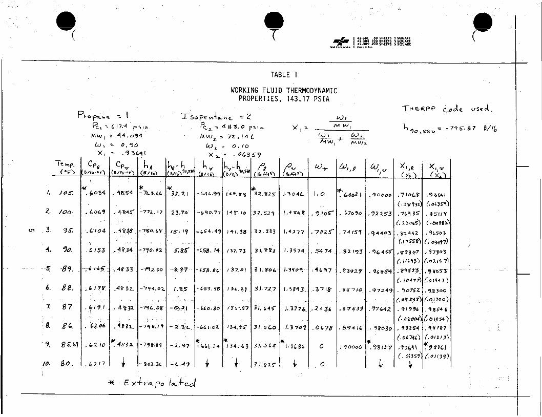
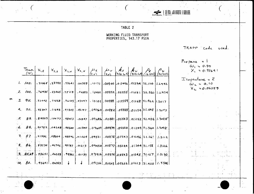
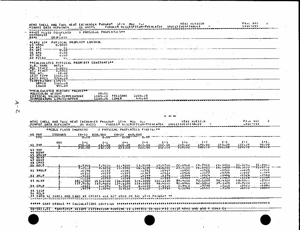
4 code was acqui red f rom t h e Na t iona l Bureau o f Standards and was subse- quen t l y used t o p r o v i d e much more s a t i s f a c t o r y t r a n s p o r t p r o p e r t i e s .
Tables 1 and 2 present t h e thermodynamic and t r a n s p o r t p r o p e r t i e s o f t h e
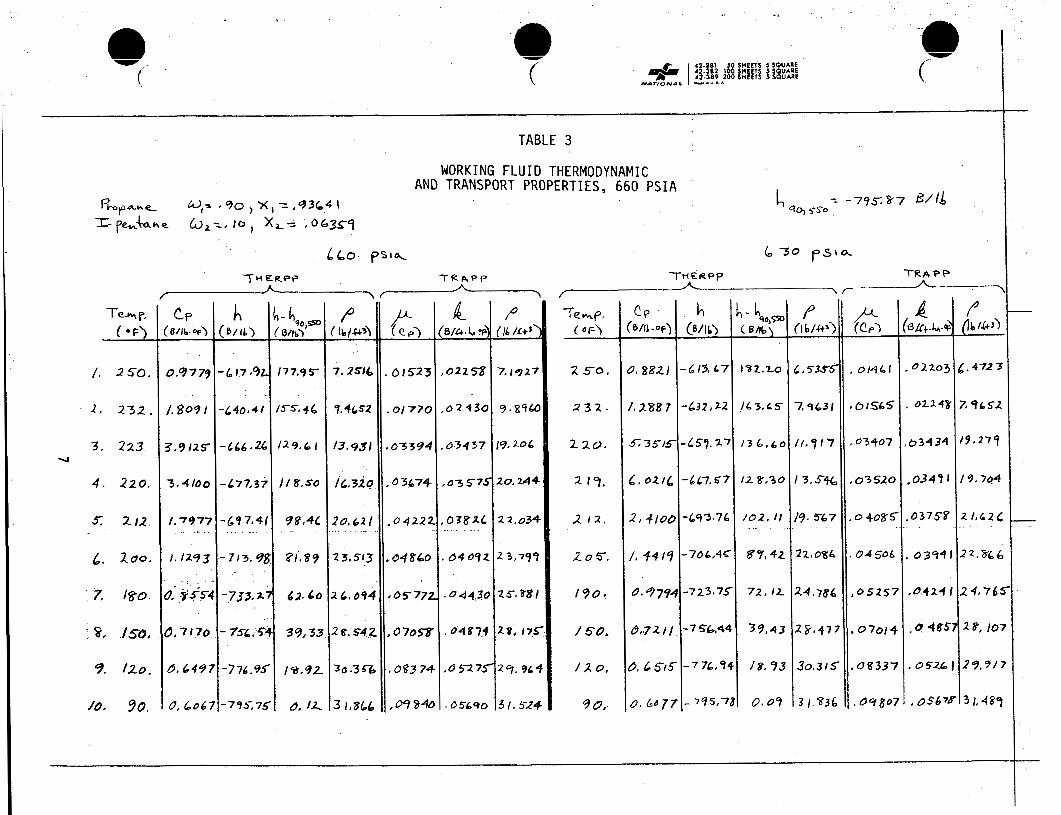
m i x t u r e a t t h e condenser pressure (143.17 p s i a ) w h i l e Table 3 presents
t h e f l u i d p r o p e r t i e s a t t h e heater pressure (630-660 p s i a ) .
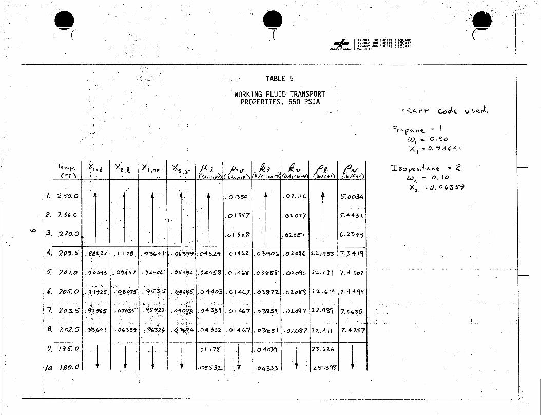
a l s o obta ined a t a pressure of 550 p s i a f o r use i n a s tudy o f s u b - c r i t i c a l
b o i l i n g i n t h e heater u n i t (Tables 4 and 5 ) .
,
P roper t i es were
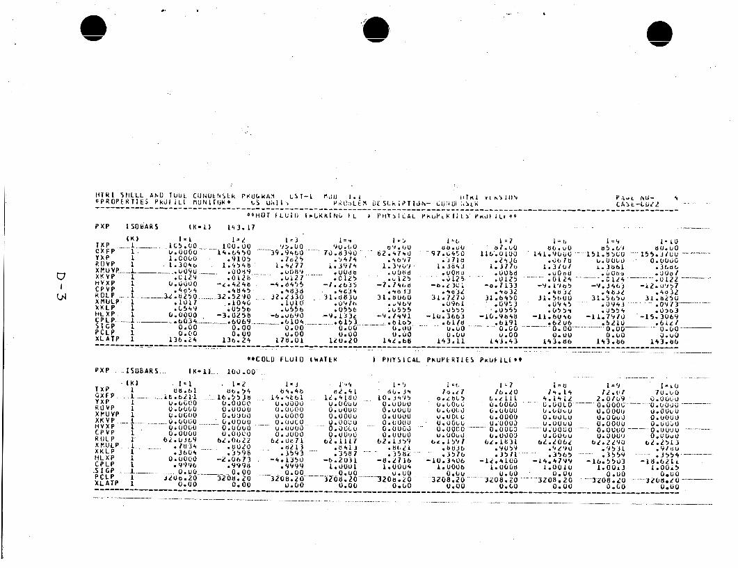
It can be seen t h a t THERPP and TRAPP p r e d i c t s l i g h t l y d i f f e r e n t mix-
t u r e d e n s i t i e s due t o d i f f e r e n t equat ions o f s t a t e .
g r e a t e s t d i f f e r e n c e s occur near t h e c r i t i c a l reg ion . The d e n s i t y i n p u t
i n t o t h e CST-1 and ST-4 codes was t h a t c a l c u l a t e d by t h e THERPP code t o
be thermodynamical ly c o n s i s t e n t .
have a s i g n i f i c a n t impact on t h e r e s u l t s o f t h i s ana lys i s .
As expected, t h e
The d e n s i t y d i f f e r e n c e s are n o t f e l t t o
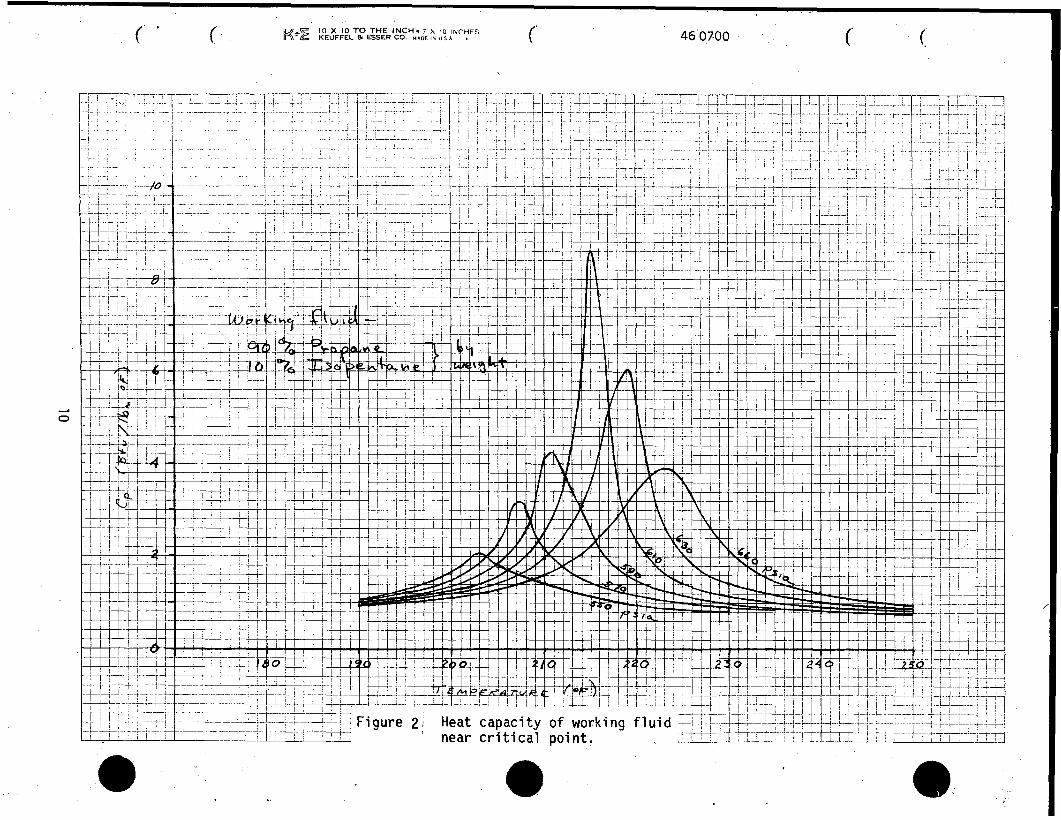
F i g u r e 2 shows t h e heat c a p a c i t y o f t h e m i x t u r e as a f u n c t i o n o f
temperature and pressure.
c r i t i c a l p o i n t can c l e a r l y be seen.
were no s i g n i f i c a n t p r o p e r t y e f f e c t s i n t h e preheater u n i t ; i t s o u t l e t
temperature was s e t a t 195OF. e f f e c t s a re t o occur i n t h e heater u n i t .
The augmentation o f heat c a p a c i t y near t h e
The heaters were s i z e d so t h a t t h e r e -. A l l b o i l i n g and n e a r - c r i t i c a l p o i n t p r o p e r t y
A working f l u i d f o u l i n g r e s i s t a n c e o f 0.0005 hr- f t2- 'F/Btu was used
i n t h i s study.
2.3.2 Geothermal F1 u i d and Cool i ng Water
Water p r o p e r t i e s were used f o r bo th t h e geothermal f l u i d and t h e cool- i n g water. The b u i l t - i n water p r o p e r t i e s i n t h e H T R I codes were used.
The geothermal f l u i d f o u l i n g r e s i s t a n c e was se lec ted as 0.0005 hr-ft2- 'F/ B tu t o be c o n s i s t e n t w i t h observed f o u l i n g c h a r a c t e r i s t i c s o f t h e R a f t
R ive r geothermal resource.
f t2-OF/Btu was c o n s e r v a t i v e l y assumed.
A c o o l i n g water f o u l i n g r e s i s t a n c e o f 0.001 h r -
4
_I ;15 il: >
+
T-
- x d n
0-
0
m ~
d 0
0
%
P
3-
42.381 50 SHEETS 5 SQUARE
42-382 42-38? 208 IC SHEETS SHEETS 5 5 &ARE QUARE
2. 100,
3. 9s;
4, 90.
,s: $9,
OI
'16. 80.
TABLE 2
WORKING FLUID TRANSPORT PROPERTIES, 143.17 PSIA
Kl > Q
t 7/06r
7 6 9 3 5
82442
88 307
8 9515
9 0 7 5 2
9 1996
9 3 2 5 4
836.4 I
9364 I
X2,P
28 932
- 23065
. 17558
, 11693
. I 6 4 77
,08004
- 06359
. 9 364 I
, 9 5 1 1 8
, 9 6 SO3
f 9r3m
, 9854c
c
* 519 47
,01760
.o f 454
. 61/37
4
; -i ... . .
(- 4’2.381 50 SHEETS 5 SQUARE 42-382 I 0 SHEETS 5 SQUARE 42-389 280 SHEETS 5 SQUARE
-
/ e 250.
1 , 2 3 2 .
3 . 223.
4 . 2 2 0 .
-4
7. lgo.
8. /si.
9. 120.
10- 90.
660 T H ERPP
h CP
Wlb-oF)
0.9779
1.809 I
r.9 I 2 5
3.4160
f .7977
I . 1193
1.- 95Y4
1,7170
3 .6492
0,6067
TABLE 3
WORKING FLUID THERMODYNAMIC AND TRANSPORT PROPERTIES, 660 PSIA
-- -79597 B / I J c, 40) 5-so
,4 B1cc.L-9
.02203
, ozasg
6 3 4 3 4
,034 9 I
, 03758
, 0 3 9 4
4 4 2 4 I
. o 485
.05.?6
. os671
P A b
6 . 4 7 2 3
74 96 52
1 9 . 2 7 7
1 9 . 7 0 4
21 ,626
22.866
2 4 , 7 6 5
28, 107
29.9/7
3 L4S7

c
TABLE 4
WORKING FLUID THERMODYNAMIC PROPERTIES, 550 PSIA
1, gp/;,,,,o
T 9 9 .?4
96.74
94 643
Q L 6 6
4 1 .45
__- - 79.7.2
63.94
j . zso.0
2. 236 .0
03 3. 220.0
0.7303
3,7 359
0.9%2'I
f . 4 8 2 5 y: -6 9 C .I3
- 69908
t .82 925
.8$-404
,97433
. BSSBi
.9000
I
1,5715
1.6 I 9 2 - ? 0 / , 4 4 . .
/.6 590 -703.2 I
(t /. 6872 -704.42
-73 1.93
.. .
-4J
a s
\p
OM
-
6P
P
g
0
" 0
\3
so Q
3
I' I'
d.
d 0 VI
I.
I1 cj 0
d 11
I' Q
-
6
a
Q 3
: QL t-
0
e' H
c
v)
w
J
e
I- m
- e
.. .
,: -.-..
..
. ..
.' .... :
. I I
I.
..
.
.,
.
10
2.4 Cases Studied
A l a r g e number o f computer runs was r e q u i r e d t o o b t a i n a reasonably
optimum f i n a l c o n f i g u r a t i o n f o r each u n i t . Many parameters were s tud ied
i n c l u d i n g tube s ize , tube spacing, f i n s vs. no f i n s , s h e l l diameter and
length , she1 1 o r i e n t a t i o n , work ing f l u i d l o c a t i o n , e t c .
- Approximately t h i r t y runs each were needed t o o b t a i n t h e f i n a l heater
and preheater c o n f i g u r a t i o n , w h i l e t h e condenser r e q u i r e d about twenty-two
runs.
0’
I n i t i a l l y t h e heater u n i t was s p l i t i n t o a heater-superheater dual
u n i t . However, i t was decided t h a t i t would be undes i rab le t o p o t e n t i a l l y
have t h e c r i t i c a l p o i n t occur between heat exchangers w i t h t h e associated l a r g e v a r i a t i o n i n p r o p e r t i e s . Also, t h e r e would be t h e p o s s i b i l i t y o f
b o i l i n g o c c u r r i n g i n t h e wrong u n i t , r e s u l t i n g n underdesign o f one of
t h e u n i t s . Also, a s tudy showed no s i g n i f i c a n t thermal advantage t o t h e
heater-superheater dual u n i t so a s i n g l e heater was used i n con junc t i on
w i t h t h e preheater .
3.0 RESULTS
3.1 Preheater
The preheater w i 11 be r e q u i r e d t o heat 8000 1 b /h r o f 660 p s i a working
f l u i d f rom 90°F t o 195OF w i t h 10,550 l b / h r o f geothermal b r i n e e n t e r i n g a t
s i s a heat d u t y o f 615,798 B tu /h r based on t h e working f l u i d
and f l o w r a t e .
206.3OF. Th
s t a t e p o i n t s
I n i t i a l runs were used t o e s t a b l i s h t h e optimum tube s i z e and spacing.
Tube diameters f rom 3/8" t o 3/4" were i n v e s t i g a t e d , w i t h t h e 1/2" tube
l o o k i n g most promis ing. l a r g e r p i t c h t o have a lower pressure drop w i t h o u t t o o severe a p e n a l t y i n
heat t r a n s f e r so i t was se lec ted over t h e smal ler spacing.
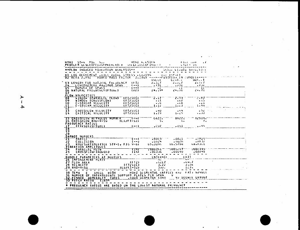
v i b r a t i o n c h a r a c t e r i s t i c s w i l l a l s o be b e t t e r f o r t h e l a r g e r spacing. Tube l a y o u t angles o f 30, 45, 60 and 90 degrees were i n v e s t i g a t e d , w i t h
t h e 90'1ayout angle p r o v i d i n g t h e b e t t e r performance and a l s o being e a s i e r
t o se rv i ce . E a r l y s t u d i e s p laced t h e h i g h pressure working f l u i d on t h e
tube s i d e bu t these runs showed t h a t t h e heat exchangers were r e l a t i v e l y
smal l i n diameter, i n d i c a t i n g t h a t t h e r e probably would n o t be a severe
p e n a l t y p laced on s h e l l t h i ckness i f t h e h i g h pressure f l u i d was p laced
on t h e s h e l l s i de . I n a d d i t i o n , t h e work ing f l u i d f i l m c o e f f i c i e n t was
t h e lowest and e x t e r n a l f i n s c o u l d be used t o b r i n g t h e working f l u i d thermal r e s i s t a n c e more i n l i n e w i t h t h e geothermal f l u i d r e s i s t a n c e .
Since n e i t h e r tube v i b r a t i o n o r s h e l l s i d e pressure drop was a problem w i t h
t h i s u n i t , h o r i z o n t a l segmental b a f f l e s were se lec ted f o r t h e i r b e t t e r
heat t r a n s f e r c h a r a c t e r i s t i c s .
Runs f o r p i t c h e s of 0.625" and 0.688" showed t h e
Cleaning and
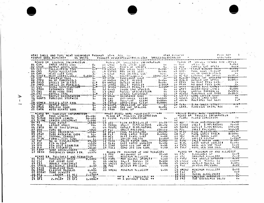
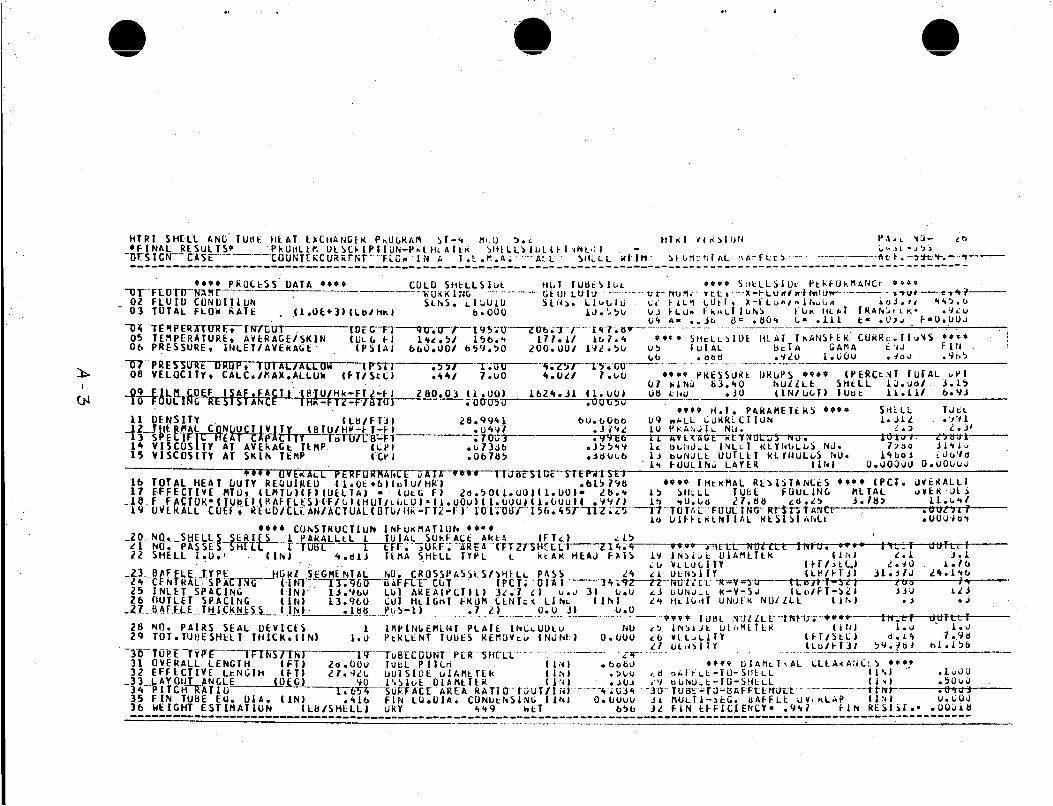
The s p e c i f i c a t i o n s o f t h e preheater se lec ted f o r t h i s a p p l i c a t i o n a re d e t a i l e d i n Table 6 and t h e summary computer p r i n t o u t f rom t h e ST-4 code
i s shown i n Appendix A. u n i t w i t h a 4.813 i n c h I.D. and 34.9% h o r i z o n t a l c u t segmental b a f f l e s .
The 24 Admi ra l t y metal tubes are e x t e r n a l l y f i n n e d w i t h 19 f i n s / i n c h and
a nominal O.D. o f 0.500 inch.
The preheater i s a 28 f o o t h o r i z o n t a l E -she l l
12
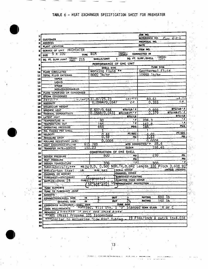
TABLE 6 - HEAT EXCHANGER SPECIFICATION SHEET: FOR PREHEATER
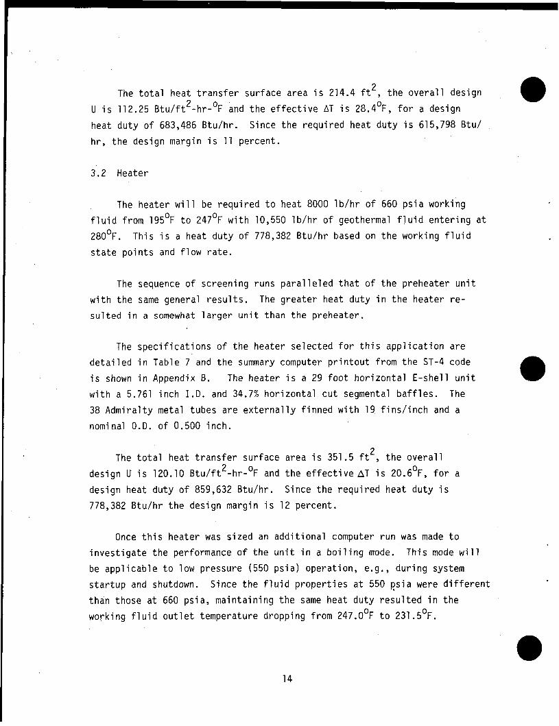
The t o t a l heat t r a n s f e r sur face area i s 214.4 ft2, t h e o v e r a l l des ign
Since t h e r e q u i r e d heat du ty i s 615,798 Btu/
2 U i s 112.25 B t u / f t -hr-'F and t h e e f f e c t i v e AT i s 28.4OF, f o r a design
heat du ty o f 683,486 Btu /hr .
h r , t h e des ign margin i s 11 percent .
3.2 Heater
The heater w i l l be r e q u i r e d t o heat 8000 l b / h r o f 660 p s i a working
f l u i d f rom 195OF t o 247OF w i t h 10,550 l b / h r o f geothermal f l u i d e n t e r i n g a t
28OoF.
s t a t e p o i n t s and f l o w r a t e .
Th is i s a heat du ty o f 778,382 Btu /hr based on t h e work ing f l u i d
The sequence o f screening runs p a r a l l e l e d t h a t o f t h e preheater u n i t
w i t h t h e same general r e s u l t s . s u l t e d i n a somewhat l a r g e r u n i t than t h e preheater .
The g rea te r heat du ty i n t h e heater r e -
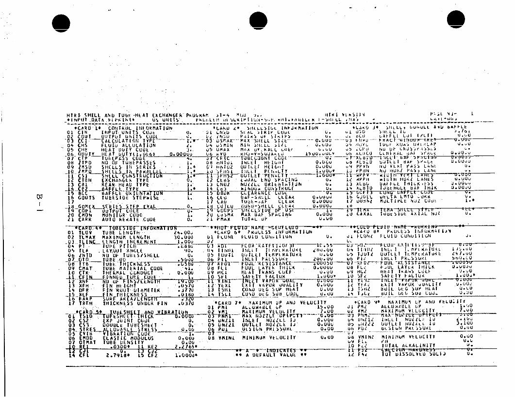
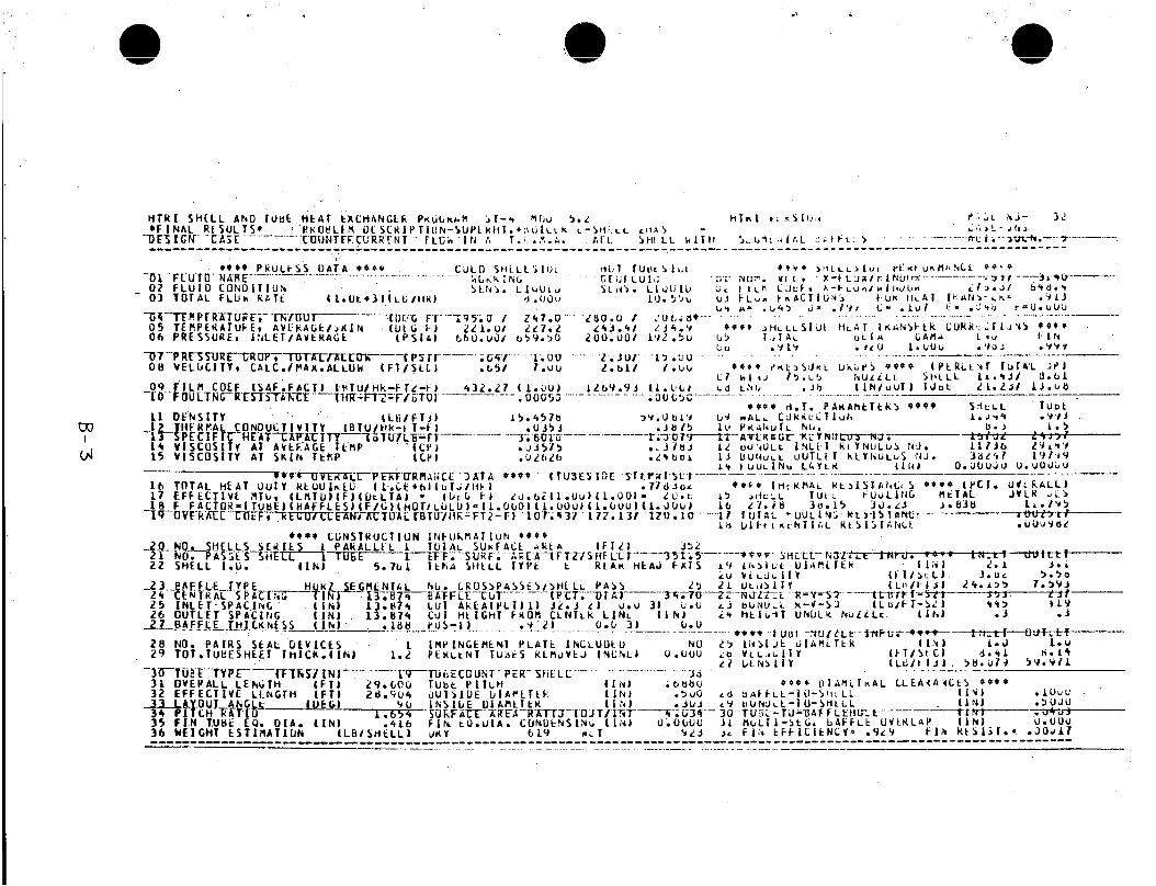
The s p e c i f i c a t i o n s o f t h e heater se lec ted f o r t h i s a p p l i c a t i o n a r e
d e t a i l e d i n Table 7 and t h e summary computer p r i n t o u t from t h e ST-4 code
i s shown i n Appendix B. The heater i s a 29 f o o t h o r i z o n t a l E -she l l u n i t
w i t h a 5.761 i n c h I . D . and 34.7% h o r i z o n t a l c u t segmental b a f f l e s . The
38 Admi ra l t y meta l tubes are e x t e r n a l l y f i n n e d w i t h 19 f i n s / i n c h and a
nominal O.D. o f 0.500 inch .
The t o t a l heat t r a n s f e r sur face area i s 351.5 ft2, t h e o v e r a l l 2 des ign U i s 120.10 B t u / f t -hr-'F and t h e e f f e c t i v e AT i s 20.6OF, f o r a
des ign heat du ty o f 859,632 Btu /hr .
778,382 Btu /hr t h e des ign margin i s 12 percent .
Since t h e r e q u i r e d heat du ty i s
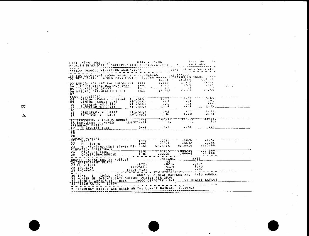
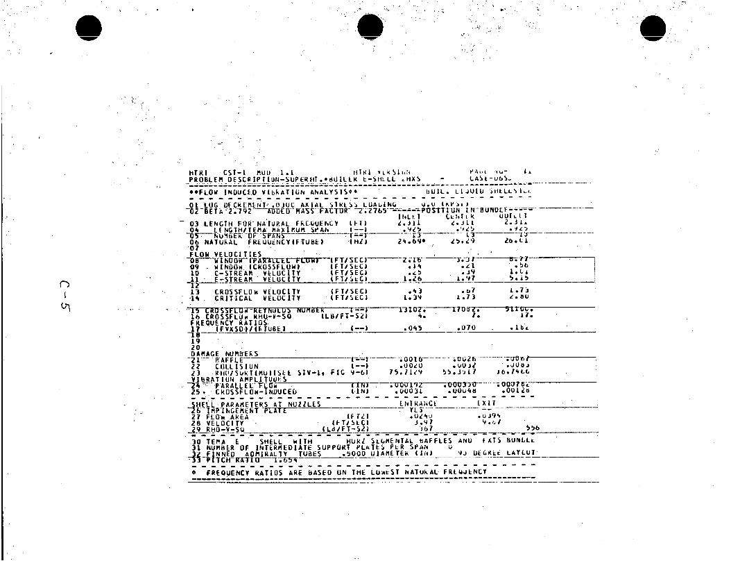
Once t h i s heater was s i zed an a d d i t i o n a l computer r u n was made t o
i n v e s t i g a t e t h e performance o f t h e u n i t i n a b o i l i n g mode.
be a p p l i c a b l e t o low pressure (550 p s i a ) opera t ion , e.g., d u r i n g system
s t a r t u p and shutdown.
than those a t 660 ps ia , ma in ta in ing t h e same heat du ty r e s u l t e d i n t h e
work ing f l u i d o u t l e t temperature dropping f rom 247.OoF t o 231.5OF.
Th is mode w i l l
Since t h e f l u i d p r o p e r t i e s a t 550 p s i a were d i f f e r e n t
14
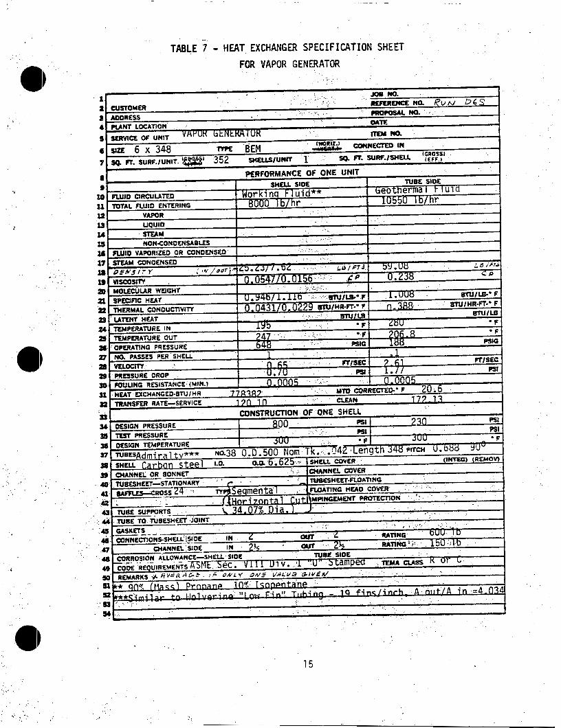
- TABLE 7 - HEAT EXCHANGER SPECIFICATION SHEET
FOR VAPOR GENERATOR
. .
15
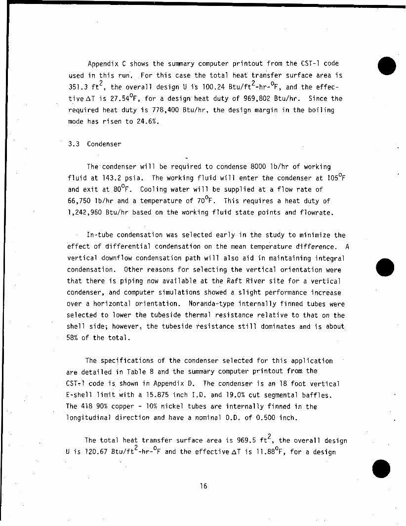
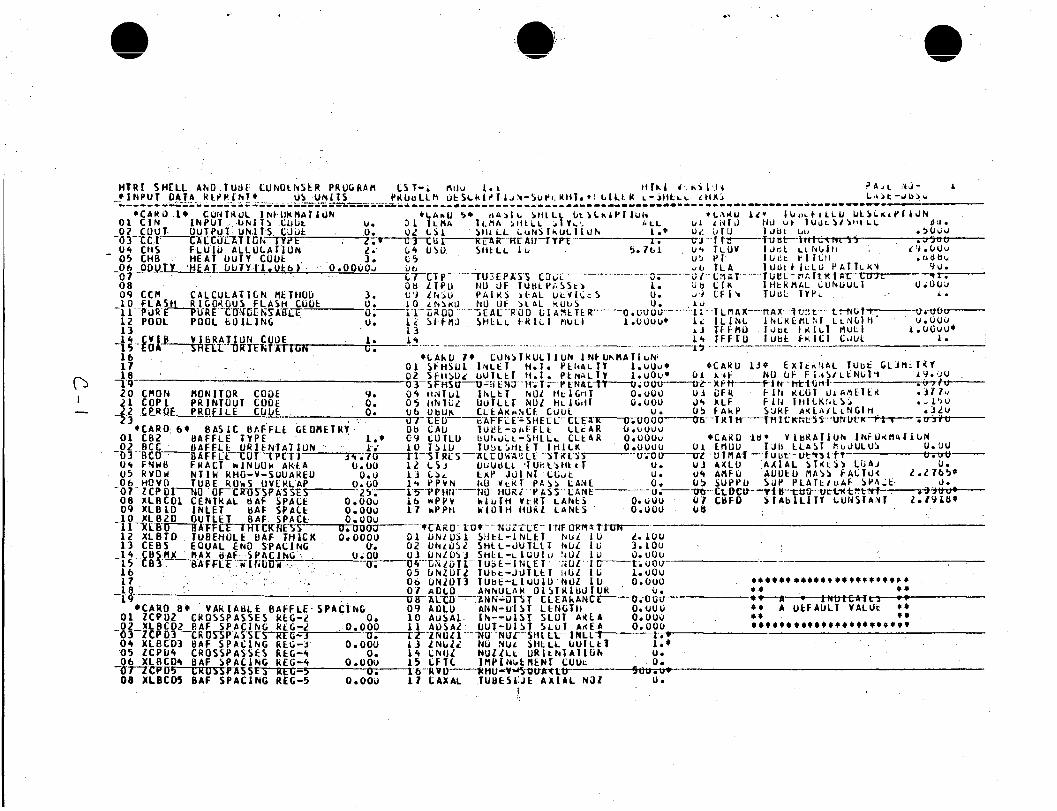
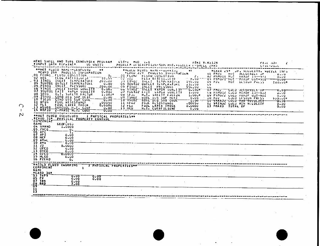
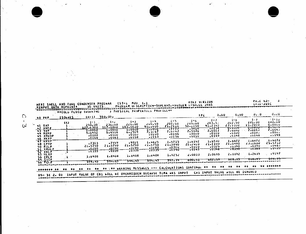
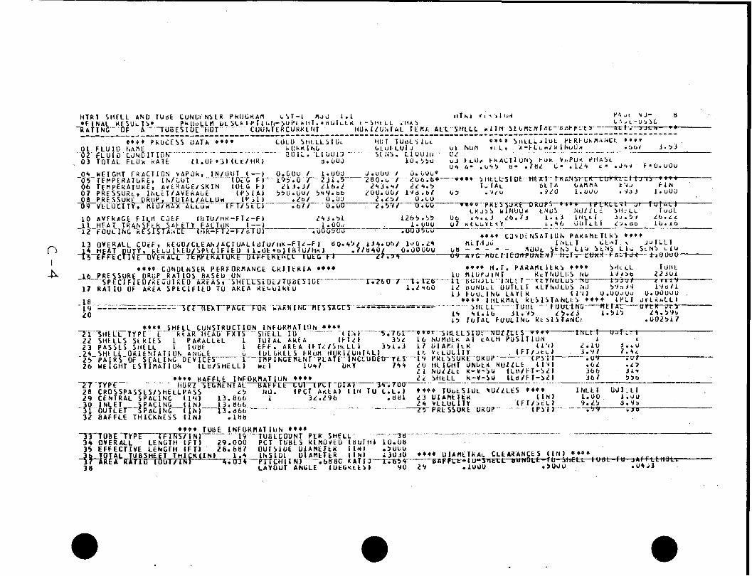
Appendix C shows t h e summary computer p r i n t o u t f rom t h e CST-1 code
used i n t h i s run.
351.3 ft2, t h e o v e r a l l des ign U i s 100.24 B t u / f t -hr-OF, and t h e e f f e c -
t i v e A T i s 27.54OF, f o r a des ign heat du ty o f 969,802 Btu /hr .
r e q u i r e d heat du ty i s 778,400 Btu /hr , t h e des ign marg in i n t h e b o i l i n g
mode has r i s e n t o 24.6%.
For t h i s case t h e t o t a l heat' t r a n s f e r sur face area i s 2
Since t h e
3.3 Condenser
"4
The' condenser w i 11 be r e q u i r e d t o condense 8000 1 b / h r o f work i ng
f l u i d a t 143.2 ps ia .
and e x i t a t 8OoF.
66,750 l b / h r and a temperature o f 7OoF.
1,242,960 Btu /hr based on t h e work ing f l u i d s t a t e p o i n t s and f l o w r a t e .
The work ing f l u i d w i l l en te r t h e condenser a t 105OF
Coo l ing water w i l l be supp l i ed a t a f l o w r a t e o f
Th is r e q u i r e s a heat du ty o f
I n - tube condensation was se lec ted ear y i n t h e s tudy t o min imize t h e
e f f e c t o f d i f f e r e n t i a l condensation on t h e mean temperature d i f f e r e n c e . A
v e r t i c a l downflow condensation pa th w i l l a so a i d i n ma in ta in ing i n t e g r a l condensation. Other reasons f o r s e l e c t i n g t h e v e r t i c a l o r i e n t a t i o n were
t h a t t h e r e i s p i p i n g now a v a i l a b l e a t t h e R a f t R i v e r s i t e f o r a v e r t i c a l
condenser, and computer s imu la t i ons showed a s l i g h t performance increase
over a h o r i z o n t a l o r i e n t a t i o n . Noranda-type i n t e r n a l l y f i n n e d tubes were
se lec ted t o lower t h e tubes ide thermal r e s i s t a n c e r e l a t i v e t o t h a t on t h e
s h e l l s ide; however, t h e tubes ide r e s i s t a n c e s t i l l dominates and i s about
58% o f t h e t o t a l .
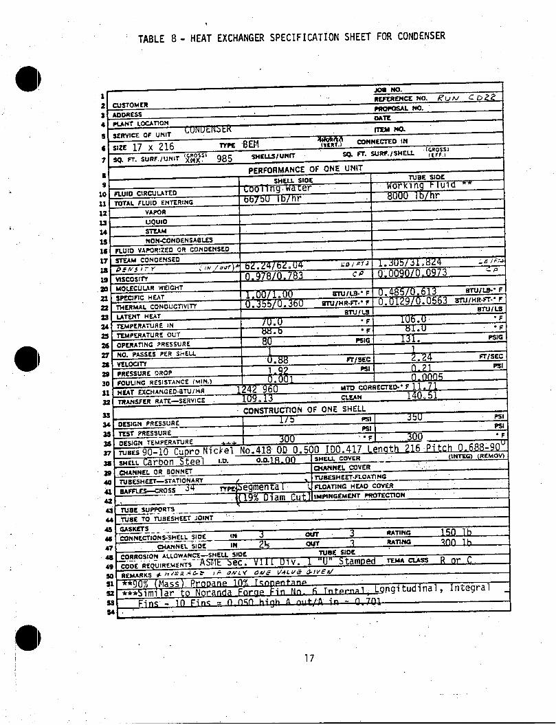
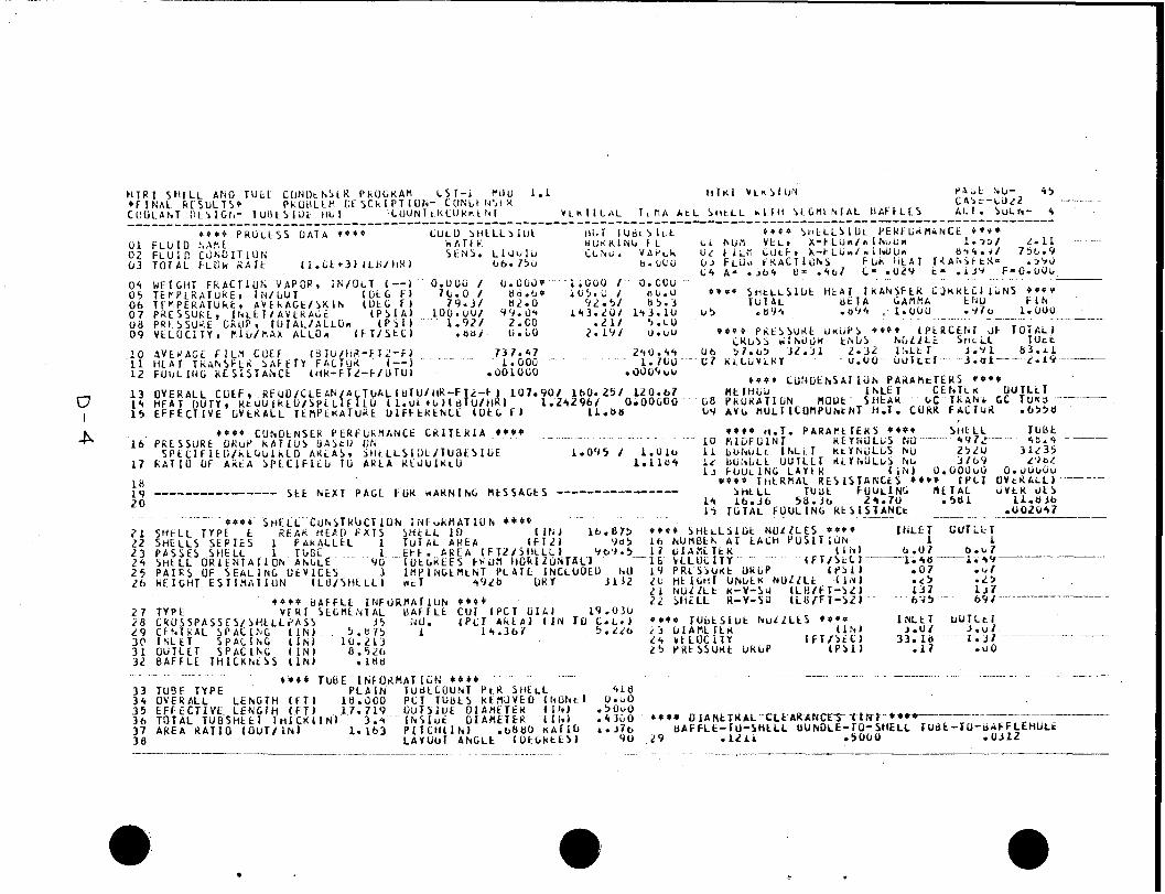
The s p e c i f i c a t i o n s o f t h e condenser se lec ted f o r t h i s a p p l i c a t i o n
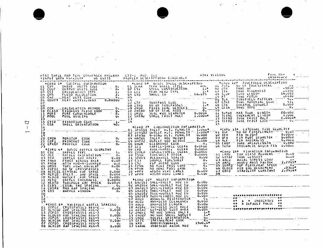
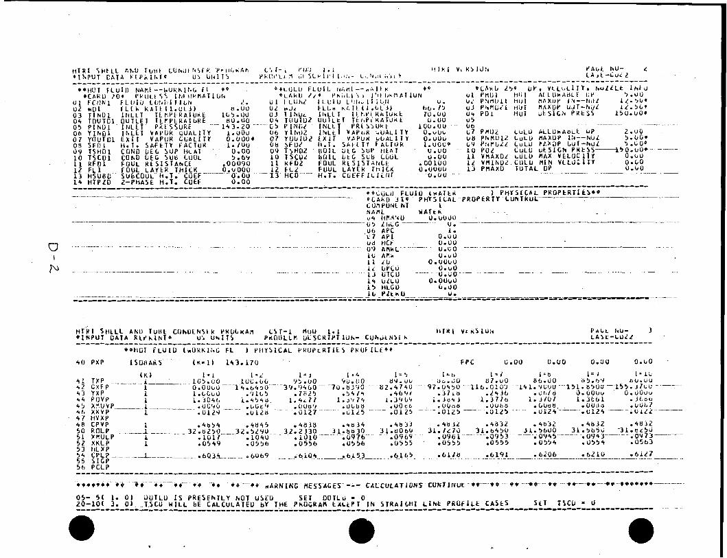
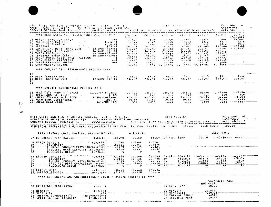
are d e t a i l e d i n Table 8 and t h e summary computer p r i n t o u t f rom t h e CST-1 code i s shown i n Appendix D.
E -she l l l i m i t w i t h a 15.875 i n c h I . D . and 19.0% c u t segmental b a f f l e s .
The 418 90% copper - 10% n i c k e l tubes are i n t e r n a l l y f i n n e d i n t h e
l o n g i t u d i n a l d i r e c t i o n and have a nominal O.D. o f 0.500 inch .
The condenser i s an 18 foo t v e r t i c a l
The t o t a l heat t r a n s f e r sur face area i s 969.5 ft2, t h e o v e r a l l -design 2 U i s 120.67 B t u / f t -hr-'F and t h e e f f e c t i v e AT i s 11.88OFY f o r a des ign
16
,
TABLE 8 - HEAT EXCHANGER SPECIFICATION SHEET FOR CONDENSER
! 17
heat duty of 1,389,836 B t u / h r . B t u / h r , the design margin i s 1 2 percent.
Since the required heat duty i s 1,242,960
18
4.0 CONCLUSIONS
The heat exchangers f o r t h e 60 kW t e s t f a c i l i t y a t R a f t R ive r have been
Design c o n s t r a i n t s f o r each heat exchanger i nco rpo ra ted i n t o t h i s s ized .
s tudy were t o a t t a i n a minimum heat t r a n s f e r area w i t h a 10% design marg in
when fou led.
water pressure drops were l e s s than 2 p s i .
Working f l u i d pressure drops were kep t under 5 p s i , w h i l e
In - tube condensation was se lec ted t o improve t h e condenser performance
by encouraging i n t e g r a l condensation. Hopefu l l y , t h e e f f e c t o f t h i s can
be checked du r ing t h e t e s t program, perhaps by va ry ing t h e work ing f l u i d
f l o w r a t e t o vary f rom a h i g h shear (good m ix ing f o r i n t e g r a l condensation)
t o a low shear (poor m ix ing f o r d i f f e r e n t i a l condensation) f l o w regime
and mon i to r i ng t h e performance o f t h e condenser.
19
5.0 REFERENCES
1. 0. J . Demuth, "Analyses o f Mixed Hydrocarbon B ina ry Thermodynamic Cycles f o r Moderate Temperature Geothermal Resources", PG-G-80-041, February 1981.
2. Personal communication w i t h C. J . Bliem, Geothermal Branch, February 1981 .
3. R. S. Deeds, "THERPP - A Thermodynamic P r o p e r t i e s Program", TREE-1081,
4. J . F. Ely and H. J . M. Hanley, "A Computer Program f o r t h e P r e d i c t i o n
August 1979.
o f V i scos i t y and Thermal C o n d u c t i v i t y i n Hydrocarbon M ix tu res " , Technical Note t o be publ ished, Na t iona l Bureau o f Standards, Boulder, CO, TBP.
20
. .
( . , . . . - .
. . ' .
APPENDIX A
COMPUTER OUTPUT OF ST-4 RUN FOR PREHEATER
( P a g e s A-1 t o A - 4 )
A- i
. ... - -- .. .
* C A R D lo* P H Y j l L A L P R O P L K T Y L O h T K O L 0 3 H R M N 0.0000 0 s APC A. 05 A P I u; ou- O b AMU 0.00 0 7 H C F 0.UO
* * C A L C U L A T k D P H Y S I C A L P R O P E R T Y C O N S T A N I s * *
- - - _ - ~ ___________ - - _ _ _ ___- _ _ ___
--___ U. __. 0 8 P Z E R O
5 0 P X P I S O B A R S t K = 1 ) 630.000 ( K - 2 ) 6b0.000 FPC 0 . v u . u u o ; o u I 7 I m - - - -
.,
4
0.1 I
-1
I
-1
L
ZI
I
;:I --I
I
__ I a
-1
Z
I
<'I a
Ut-
OW
I 2
m
-IN
OD
I I
!
El
! i
I
A-4
. ,. . ,
. .. I .
APPENDIX B
COMPUTER OUTPUT OF S T - 4 RUN
FOR HEATER
( P a g e s B - 4 t o B-4)
\
B - i
w I I
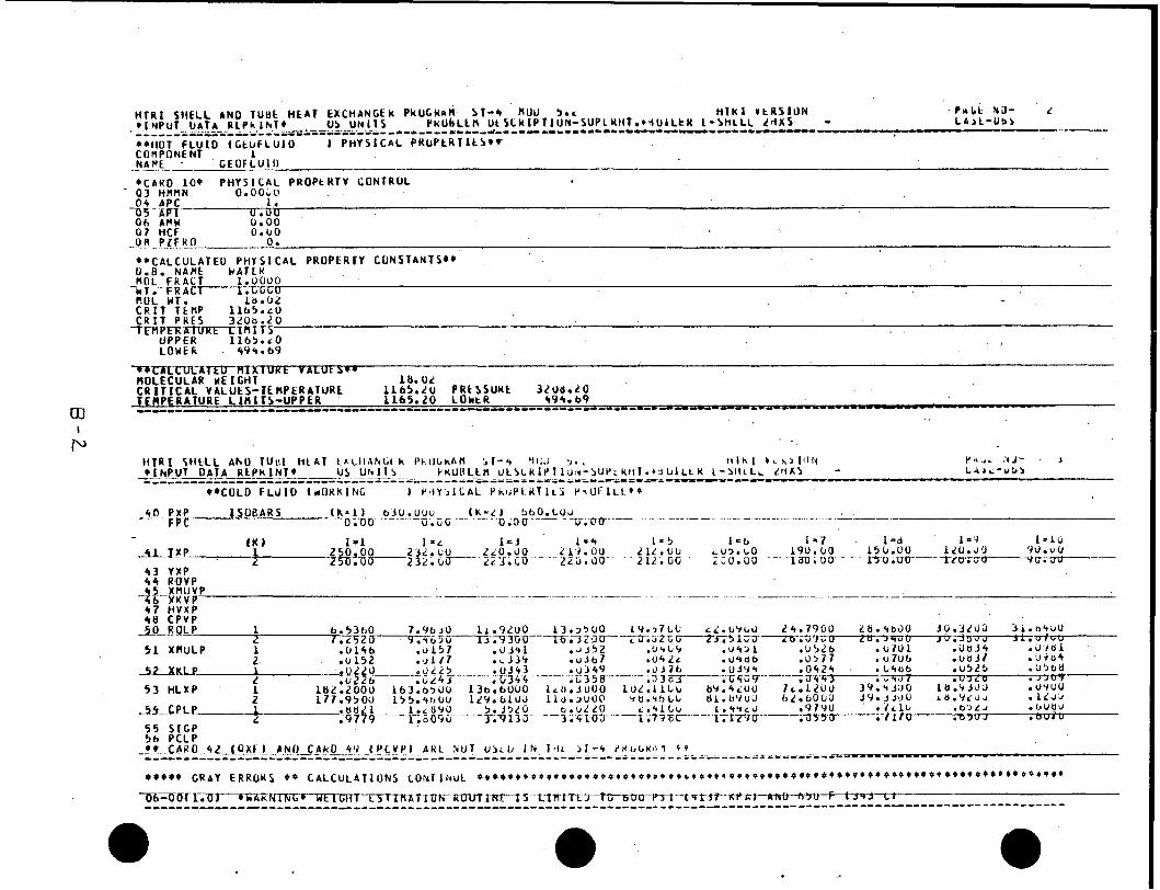
* * C A L C U L A T E D P H I S I C A L P R O P E R l Y C O N S T A N T S * * 0.0. N A f l E k A J E K R O L F R A C T 1.0000 - r . T i t G U R U L WT. 1a.OL C R I T T E N P 1 1 6 5 . L O C R I T P R E S 3LOb.20
-k T .- FR A Cl
w crl I
.I I
d
.z I I
.- -3 I 2
-I-
.... I .. 0
-
I-
tv
- rn
f;
I
z
c 3
* t 31 -1
I I - I I i
uG
va
0
4
I 3
31
3 3
01
I 1-
-I
2
-1
- I 1
€3- 4
I .
APPENDIX C
,-
I .
-:,* I ;
COMPUTER OUTPUT OF CST-1 RUN
FOR HEATER' (BOIL1NG MODE)
( P a g e s C - 1 t o C-5)
. .... -
. .. -. . . . .
C - i
il
3
3
> . >oo
DU
O
30
h
0.
. i to :2q
I 1
I.
5 au
ms
rlc w
~ J
Z+
pO
OO
' I
I I I I I I I I I I I I I i I I I I I I 1 I I I I I I I I I I I i I I I I I I I I I I 1 I I I I I I I I I I I
O
I-
1.A
la
I
-
ll-
Id
Ir
y
IO
1
0
iZ I 1
4:
I vc
I-
:
I *: I *c IS
I n.3
30s
33s
303
..
I
I I I I I I I I I I I I I I I I i I 4 I I I I I I I
I I I I I I i i i I I I I
I I I I I I I I I I I 1 I I I I I I I 1 1 I 1 I I I I I I I I I I i I i
4
-*
C
9
ur
n
C 30
L
WK
C
ZU
c-2
:
3 4
I
I I
I c
.I
c-3
, . .I
H U R L S t b R E N T A L b A F F L E S ANU f A T S M U N L L L
. --. . .
APPENDIX D
COMPUTER OUTPUT OF CST-1 RUN FOR CONDENSER
(Pages D-1 to D - 6 )
D- i
..... .. __ ......................... ......................................
cc
1
I Irr~
rrrrrrrl-rrc
rrr u1
-0
I I
W
I I
II
I o.
I- 0
hC
0C
CC
Crn
i
Ir;
! 2
......
......
e c
L
r
0
c 0 0
i!
I
1
I I
,
IN
I
'
Id
I
b
I c
ac
ch
uu
rc
cc
cc
CL
C -
1 e
. tu
Gc
L.C
cc
CC
CP
. I)
I C
h c c c
ah
u c C
IC c c c
i L
i
I ooc*u* ciGCCcCcuC
I-
N r
a
hiC
OO
OC
00
I
o ...
......
... 3
0 ...
......
... .c
oC
2C
cc
LL
rC
CC
GC
Ch
C-
0.
0 C
ru
Cu
cC
oc
to
r.
I.
CN
CC
C~
UL
OC
CO
CO
~~
U
00
0C
CG
rL
cC
OG
CC
GrO
I I
,I
u
ro
.
hr +e
hc
Ce
Cc
cZ
. 0 ...
......
... -d
Ow
cC
~L
Eh
CC
eC
CC
rC
-
e . OV
~h
CC
OC
CC
OI. 11
CN
C~
C~
S~
CC
C~
CC
~~
Q
eo
tC
Cu
ch
cC
tC
CO
hc
L
P .= I
41 WE
z
oo
co
cc
c
i 2 ..
......
.... 4
CU
CO
Ub
CN
CC
CC
OC
CC
-
I C
fU
U-U
CC
CC
CC
C.
I
I C
~C
WP
WC
CC
cc-crc.~
C-
I
OC
OW
r D
CL
CC
CC
CC
CC
C
41 -E
z
oo
co
cc
c
! 2
......
..... 0
4
Jc
~C
oC
bC
NC
cC
CO
CC
C-
I e
Cf~
u-u
Cc
cC
cC
C. I
I C
~C
WP
WC
CC
cc-crc.~
C-
I
OC
OW
r D
CL
CC
CC
CC
CC
C
Ii
ii
.i
'I
il I I I 'I
!I
&
-I
r U
r
jc
rz
r
't
...
......
.....
i; i
I
ia
I-
O(
t
-1
z
I I I 1 I I I I I I I I I I I I I I P
-c
I >
>
1 V'
c
II
I
CP
I
CC
I
XI
I
h
I I IC
I r
p
r i .
0 4 05 06 07 08 0 9
10 1 1 12
13 1 4 15
16
17 AH 19 2 0
21 22 23 2 4 25 26
2 7 2 6 2 9 3 0 3 1 3 2
7 3 1 . 4 7 _ _ _ L .OOO
. O O L O t i O
240.44 I. 760 . GOO', b V
c .
,i
t i . ~ i I I . ' I l L I A d . +
'I .I . t' 1 4 J . 3 3 I , ? , . 5 2
V A P U R R t Y h U L L J h U f l b t K C C N T k O L L I N C K L G l h E
. .. .. .. . . .. -__ .-. .
I
* e * * S U E C O U L l h C A N D S U P E K H t A T I k G f l i A T U K L P H Y S I C A L P I ( i I Y E R T l t 5 e * * *
- -- ._. - 30 F E F L R E N C E T E R P E R A T U * E
3 1 D E N S I T Y . .. - __-.__ ( L b l f T 3 ) 32 V I S C O S I T Y i C P 1 3 3 T H E R M A L C O N D U C T I V I T Y ( B T U / H R - C T - F l 3 4 S P E C I F I C H L A T C A P A C I T Y 4 bTU/LB-F )
. ~ .~ __ -~ . . . . . . . . . . . -- . -- .. . ... . .. .. . . .. . -
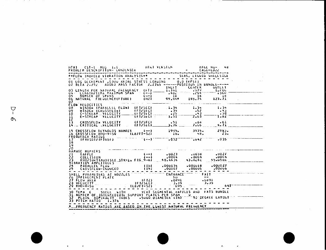
15 CROSSFLOW CLYhULOS NUNSER t--) 19Y5. 3'4350 2 9 6 3 , 16 CROSSFLUM RHO-V-SO t L S / F T - S L ) A 6. 51). 230 . D 35.- (--)--- .032 --...- FREOUEhCY R A T I b S .-.I--._ -__ 1 7 t F V X S U l / ( t T U b f 1 1 8
u4z
- - - ___ F X I T - -- SHELL P A R C f l t T t R S A T N O l l L E S E EIT K A Ec C L -- - 2 6 I P P I h G L f l t N T P L A T E hU 2 7 FLUU AhLA ( F T Z I o O d V l . b a 9 i 2 8 VFLUCITY I F T / S t C I 3 . 3 4 3 . 3 5 29 RHU-V-SU (LM / F T - S 2 J 6 Y 5
c .,