Embed Size (px)
Citation preview
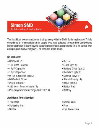
Page 1
Simon SMDKit Information & Instructions
This is a kit of loose components that go along with the SMD Soldering Lecture. This is considered an intermediate kit for people who have soldered through-hole components before and wish to learn how to solder surface mount components. This kit comes with a preprogrammed ATmega328. All parts are listed below.
Kit includes:
Additional Tools Needed:
•NCP1402 IC•10k Ohm Resistor•47μF Capacitor•10μF Capacitor•0.1μF Capacitor (qty: 2)•MBRA140 Diode•22μH Inductor•330 Ohm Resistors (qty: 4)•Pre-programmed ATmega328 TQFP IC
•Tweezers•Soldering Iron•Solder
•Solder Wick•Flux•Eye Protection
•Buzzer•LEDs (qty: 4)•Battery Clips (qty: 2)•Switches (qty: 2)•Screws (qty: 4)•Standoffs (qty: 4)•Bezel Frame•Button Pad•Battery
Page 2 Page 3
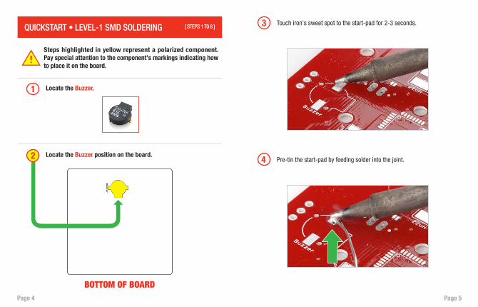
Don’t: Use the very tip of the iron.
Do: Use the side of the tip of the iron, “The Sweet Spot.”
Do: Touch the iron to the component leg and metal SMD pad at the same time.
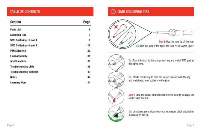
Parts List
Soldering Tips
SMD Soldering • Level 1
SMD Soldering • Level 2
PTH Soldering
Final Assembly
Additional Info
Troubleshooting LEDs
Troubleshooting Jumpers
Notes
Learning More
Section
1
3
4
16
22
34
36
38
40
42
44
Page
Do: While continuing to hold the iron in contact with the leg and metal pad, feed solder into the joint.
Do: Use a sponge to clean your iron whenever black oxidization builds up on the tip.
Don’t: Glob the solder straight onto the iron and try to apply the solder with the iron.
SMD SOLDERING TIPSTABLE OF CONTENTS
Page 4 Page 5
QUICKSTART • LEVEL-1 SMD SOLDERING [ STEPS 1 T0 8 ]
1 Locate the Buzzer.
Locate the Buzzer position on the board.
Steps highlighted in yellow represent a polarized component. Pay special attention to the component’s markings indicating how to place it on the board.
3 Touch iron’s sweet spot to the start-pad for 2-3 seconds.
4 Pre-tin the start-pad by feeding solder into the joint.2
BOTTOM OF BOARD
Page 6 Page 7
5
6
First, pull solder away.
Second, remove the iron.
7 Solder should cover the entire pad and look like this - a tiny pillow.
8 Using your tweezers, position the buzzer slightly away from the pad.
Page 8 Page 9
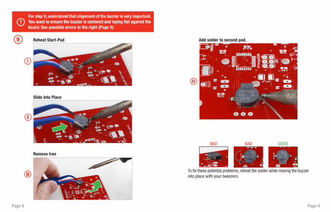
9 Reheat Start-Pad Add solder to second pad.
Slide Into Place
Remove Iron
For step 9, understand that alignment of the buzzer is very important. You want to ensure the buzzer is centered and laying flat against the board. See possible errors to the right (Page 9).
I
II
III
IV
To fix these potential problems, reheat the solder while moving the buzzer into place with your tweezers.
BAD BAD GOOD
Page 10 Page 11
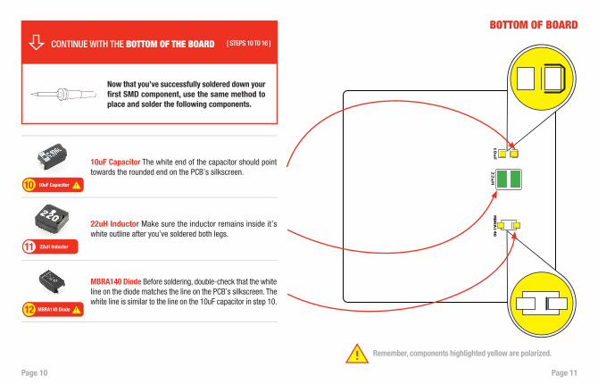
Now that you’ve successfully soldered down your first SMD component, use the same method to place and solder the following components.
10uF Capacitor
MBRA140 Diode
22uH Inductor
10
12
11
10uF Capacitor The white end of the capacitor should point towards the rounded end on the PCB’s silkscreen.
MBRA140 Diode Before soldering, double-check that the white line on the diode matches the line on the PCB’s silkscreen. The white line is similar to the line on the 10uF capacitor in step 10.
22uH Inductor Make sure the inductor remains inside it’s white outline after you’ve soldered both legs.
BOTTOM OF BOARD
CONTINUE WITH THE BOTTOM OF THE BOARD [ STEPS 10 T0 16 ]
Remember, components highlighted yellow are polarized.

Page 12 Page 13
0.1uF Capacitors
330 Resistors
14
13
330 Resistors These resistors are not polarized. However, they do have a value marking on the top side. Make sure the marking is facing up.
0.1uF Capacitors Ceramic capacitors like these are not polarized. They don’t have a value marking. This means they can be soldered into place in any rotation.
BOTTOM OF BOARD
Page 14 Page 15
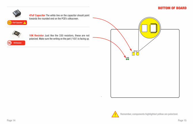
10K Resistor16
10K Resistor Just like the 330 resistors, these are not polarized. Make sure the writing on the part (‘103’) is facing up.
47uF Capacitor The white line on the capacitor should point towards the rounded end on the PCB’s silkscreen.
BOTTOM OF BOARD
Remember, components highlighted yellow are polarized.
47uF Capacitor15
Page 16 Page 17
QUICKSTART • LEVEL-2 SMD SOLDERING [ STEPS 17 T0 21 ]
Now that you’ve successfully soldered down all Level-1 components, you are ready to move on to Level-2. The next set of components have 5 or more pads each, and the pad size is smaller. Although this is more challenging, you will use the same methods as before.
17 Locate the NCP1402. Be sure to match up the legs with the pads on the PCB. This component is polarized.
Locate the NCP1402 position on the board.18
Remember, components highlighted yellow are polarized.
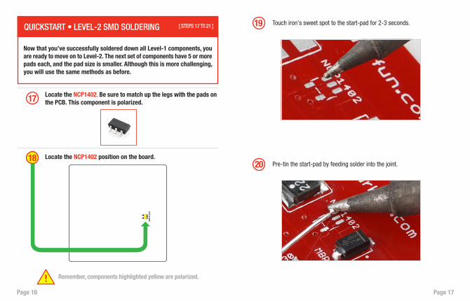
19 Touch iron’s sweet spot to the start-pad for 2-3 seconds.
20 Pre-tin the start-pad by feeding solder into the joint.
Page 18 Page 19
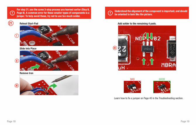
21 Reheat Start-Pad
Slide Into Place
Remove Iron
For step 21, use the same 3-step process you learned earlier (Step 8, Page 8). A common error for these smaller types of components is a jumper. To help avoid these, try not to use too much solder.
Understand the alignment of the component is important, and should be oriented to look like the picture.
I
II
III
BAD GOOD
Learn how to fix a jumper on Page 40 in the Troubleshooting section.
Add solder to the remaining 4 pads.
IV
Page 20 Page 21
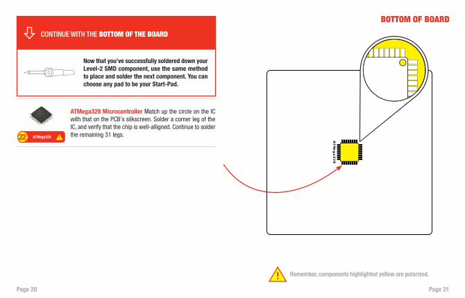
Now that you’ve successfully soldered down your Level-2 SMD component, use the same method to place and solder the next component. You can choose any pad to be your Start-Pad.
ATMega32822
ATMega328 Microcontroller Match up the circle on the IC with that on the PCB’s silkscreen. Solder a corner leg of the IC, and verify that the chip is well-alligned. Continue to solder the remaining 31 legs.
BOTTOM OF BOARD
Remember, components highlighted yellow are polarized.
CONTINUE WITH THE BOTTOM OF THE BOARD
Page 22 Page 23
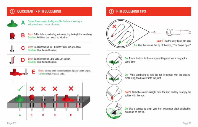
Don’t: Use the very tip of the iron.
Do: Use the side of the tip of the iron, “The Sweet Spot.”
Do: Touch the iron to the component leg and metal ring at the same time.
Do: While continuing to hold the iron in contact with the leg and metal ring, feed solder into the joint.
Do: Use a sponge to clean your iron whenever black oxidization builds up on the tip.
Don’t: Glob the solder straight onto the iron and try to apply the solder with the iron.
QUICKSTART • PTH SOLDERING PTH SOLDERING TIPS
Page 24 Page 25
TOP OF BOARD
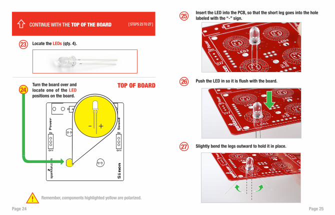
23 Locate the LEDs (qty. 4).
Turn the board over and locate one of the LED positions on the board.
24
CONTINUE WITH THE TOP OF THE BOARD [ STEPS 23 T0 27 ]
25Insert the LED into the PCB, so that the short leg goes into the hole labeled with the “-” sign.
26 Push the LED in so it is flush with the board.
27 Slightly bend the legs outward to hold it in place.
Remember, components highlighted yellow are polarized.
Page 26 Page 27
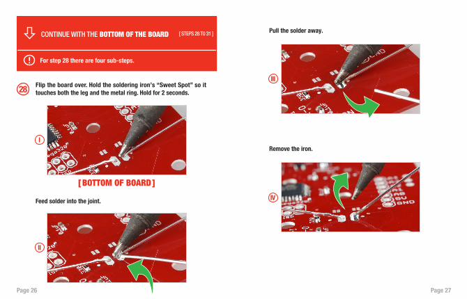
28 Flip the board over. Hold the soldering iron’s “Sweet Spot” so it touches both the leg and the metal ring. Hold for 2 seconds.
Pull the solder away.
Feed solder into the joint.
Remove the iron.
For step 28 there are four sub-steps.
I
III
II
IV
CONTINUE WITH THE BOTTOM OF THE BOARD [ STEPS 28 T0 31 ]
[ BOTTOM OF BOARD]
Page 28 Page 29
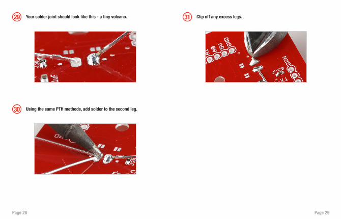
29 31
30
Your solder joint should look like this - a tiny volcano. Clip off any excess legs.
Using the same PTH methods, add solder to the second leg.
Page 30 Page 31
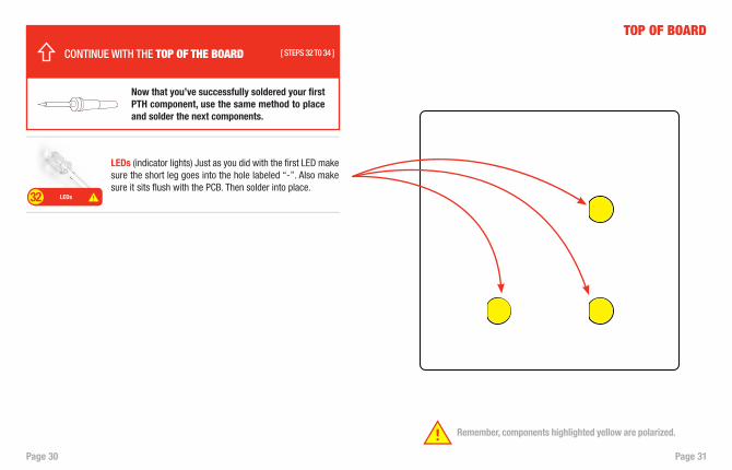
Now that you’ve successfully soldered your first PTH component, use the same method to place and solder the next components.
LEDs32
LEDs (indicator lights) Just as you did with the first LED make sure the short leg goes into the hole labeled “-”. Also make sure it sits flush with the PCB. Then solder into place.
TOP OF BOARD
CONTINUE WITH THE TOP OF THE BOARD [ STEPS 32 T0 34 ]
Remember, components highlighted yellow are polarized.
Page 32 Page 33
TOP OF BOARD
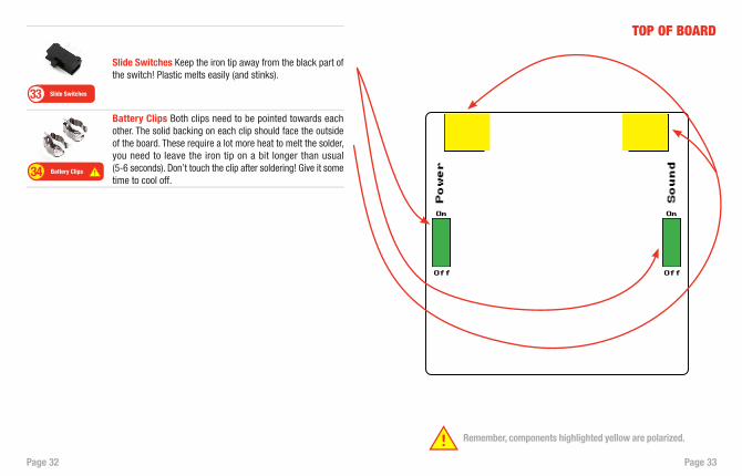
Battery Clips Both clips need to be pointed towards each other. The solid backing on each clip should face the outside of the board. These require a lot more heat to melt the solder, you need to leave the iron tip on a bit longer than usual (5-6 seconds). Don’t touch the clip after soldering! Give it some time to cool off.
Slide Switches Keep the iron tip away from the black part of the switch! Plastic melts easily (and stinks).
Slide Switches33
Battery Clips34
Remember, components highlighted yellow are polarized.
Page 34 Page 35
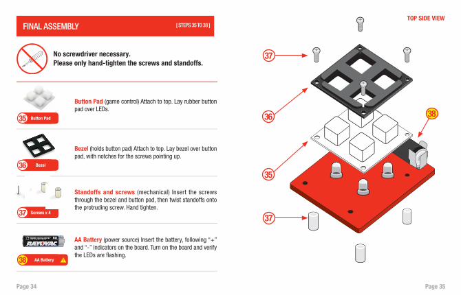
[ STEPS 35 T0 38 ]FINAL ASSEMBLY
Screws x 437
AA Battery (power source) Insert the battery, following “+” and “-” indicators on the board. Turn on the board and verify the LEDs are flashing.
Standoffs and screws (mechanical) Insert the screws through the bezel and button pad, then twist standoffs onto the protruding screw. Hand tighten.
AA Battery38
Bezel (holds button pad) Attach to top. Lay bezel over button pad, with notches for the screws pointing up.
Bezel36
Button Pad (game control) Attach to top. Lay rubber button pad over LEDs.
Button Pad35
No screwdriver necessary. Please only hand-tighten the screws and standoffs.
38
37
37
35
36
TOP SIDE VIEW
Page 36 Page 37
CREATE YOUR OWN PROJECT WITH SIMON
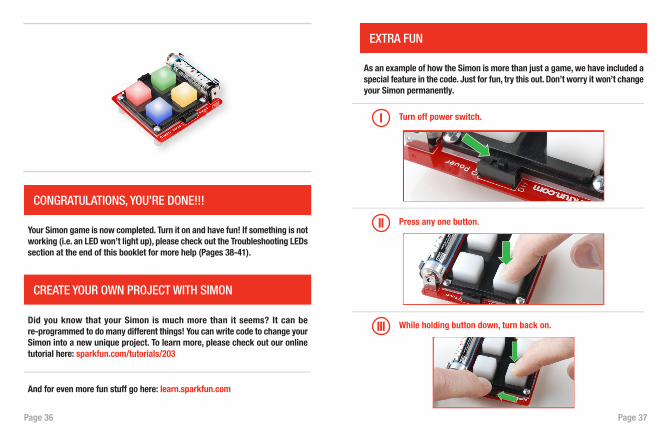
CONGRATULATIONS, YOU’RE DONE!!!
Your Simon game is now completed. Turn it on and have fun! If something is not working (i.e. an LED won’t light up), please check out the Troubleshooting LEDs section at the end of this booklet for more help (Pages 38-41).
Did you know that your Simon is much more than it seems? It can be re-programmed to do many different things! You can write code to change your Simon into a new unique project. To learn more, please check out our online tutorial here: sparkfun.com/tutorials/203
And for even more fun stuff go here: learn.sparkfun.com
EXTRA FUN
As an example of how the Simon is more than just a game, we have included a special feature in the code. Just for fun, try this out. Don’t worry it won’t change your Simon permanently.
Turn off power switch.I
Press any one button.II
While holding button down, turn back on.III
Page 38 Page 39
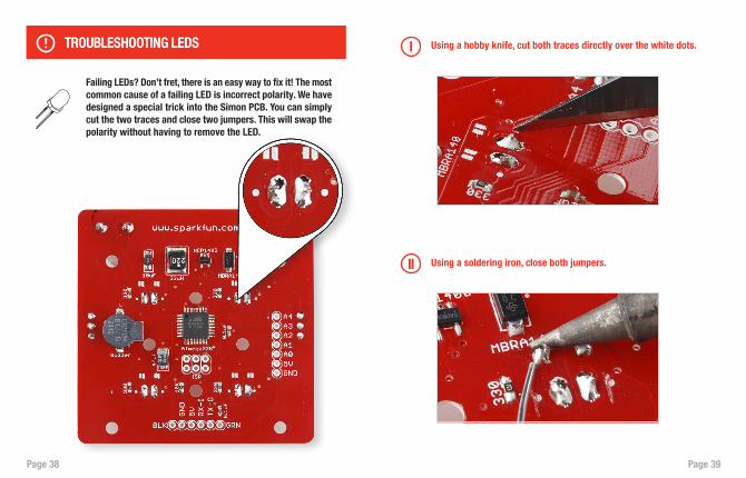
Using a soldering iron, close both jumpers.II
Using a hobby knife, cut both traces directly over the white dots.I
Failing LEDs? Don’t fret, there is an easy way to fix it! The most common cause of a failing LED is incorrect polarity. We have designed a special trick into the Simon PCB. You can simply cut the two traces and close two jumpers. This will swap the polarity without having to remove the LED.
TROUBLESHOOTING LEDSTROUBLESHOOTING LEDS
Page 40 Page 41
TROUBLESHOOTING JUMPERS
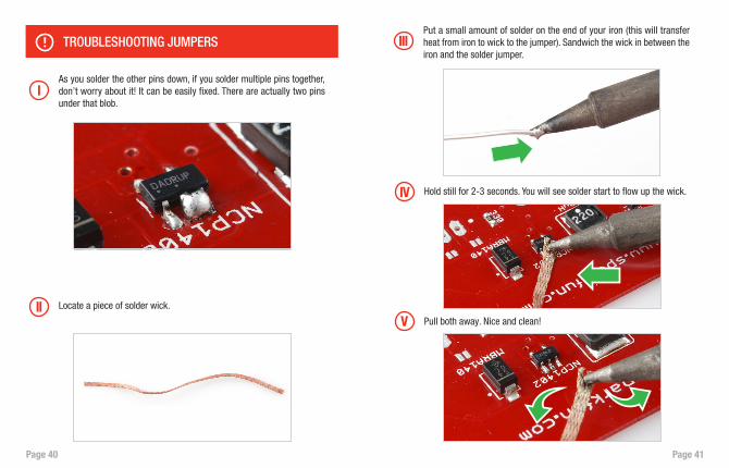
IAs you solder the other pins down, if you solder multiple pins together, don’t worry about it! It can be easily fixed. There are actually two pins under that blob.
IIIPut a small amount of solder on the end of your iron (this will transfer heat from iron to wick to the jumper). Sandwich the wick in between the iron and the solder jumper.
Hold still for 2-3 seconds. You will see solder start to flow up the wick. IV
V Pull both away. Nice and clean!
Locate a piece of solder wick.II
Page 42 Page 43
Notes
Page 44
© SparkFun Electronics, Inc. All Rights Reserved. The SparkFun Simon SMD Kit features, specifications, system requirements, and availability are subject to change without notice. All other trademarks contained herein are the property of their respective owners.
Microcontroller and PCBThe microcontroller is the brain of the game. It’s programmed to light up the buttons and create the game sequence. Bending the legs won’t hurt the chip – it is designed to withstand the heat of the soldering iron as well as gentle bending.
Try to be gentle with the board, but a few scratches are not a big deal.
Soldering
The tip of the iron is normally 700°F, hot enough to melt metal. It is normal for the handle of the soldering iron to heat up a bit. Hold it like a pencil and move your hand further away from the tip if the heat is uncomfortable. The solder smokes because the rosin inside the solder is burning off - it’s not harmful.
Buzzer and Other Components The buzzer makes the noise for the game – pretty simple! The capacitors help “clean up” the power on the board. The resistor tells the microcontroller not to reset once the power is turned on, so your game can continue uninterrupted. The slide switches turn on and off the power and sound.
LEDsLight-emitting diodes (LEDs) are like light bulbs, but much smaller and more efficient.
Buttons, Bezels, and StandoffsSquishy buttons are fun! The bezel helps hold the buttons in place. The standoffs hold the board up off a surface, helping to protect the electronics. They also hold the pad and bezel onto the board.
Learning More