Embed Size (px)
Citation preview
Copyright © 2015 Tech Science Press CMC, vol.47, no.3, pp.143-177, 2015
Simple Efficient Smart Finite Elements for the Analysis ofSmart Composite Beams
M. C. Ray1, L. Dong2 and S. N. Atluri3
Abstract: This paper is concerned with the development of new simple 4-nodedlocking-alleviated smart finite elements for modeling the smart composite beams.The exact solutions for the static responses of the overall smart composite beam-s are also derived for authenticating the new smart finite elements. The overallsmart composite beam is composed of a laminated substrate conventional compos-ite beam, and a piezoelectric layer attached at the top surface of the substrate beam.The piezoelectric layer acts as the actuator layer of the smart beam. Alternate finiteelement models of the beams, based on an “equivalent single layer high order s-hear deformation theory”, and a “layer-wise high order shear deformation theory”,are also derived for the purpose of investigating the required number of elementsacross the thickness of the overall smart composite beams. Several cross-ply sub-strate beams are considered for presenting the results. The responses computed bythe present new “smart finite element model” excellently match with those obtainedby the exact solutions. The new smart finite elements developed here reveal that thedevelopment of finite element models of smart composite beams does not requirethe use of conventional first order or high order or layer-wise shear deformationtheories of beams. Instead, the use of the presently developed locking-free 4-nodeelements based on conventional linear piezo-elasticity is sufficient.
Keywords: Piezoelectricity, exact solutions, smart finite element, smart struc-tures.
1 Introduction
In the quest for developing very light weight high performance flexible structures,a concept has emerged for developing structures with self-controlling and/or self-monitoring capabilities. Expediently, utilizing the piezoelectric effects Foreward1 Department of Mechanical Engineering, Indian Institute of Technology, Kharagpur, India.2 Corresponding Author, School of Aeronautic Science and Engineering, Beihang University, China.
Email: [email protected] Department of Mechanical Engineering, Texas Tech University, USA

144 Copyright © 2015 Tech Science Press CMC, vol.47, no.3, pp.143-177, 2015
(1981) first attempted to demonstrate the feasibility of using the piezoelectric ac-tuators to damp out the vibrations of a cylindrical fiber glass mast. Subsequent-ly, Bailey and Hubbard (1985), Bruke and Hubbard (1987), Crawley and Leuis(1987), Im and Atluri (1989), Shi and Atluri (1990) successfully reported that thepatches of piezoelectric actuators being bonded with the host beams efficiently per-form as the distributed actuators of the host beams. Miller and Hubbard (1987)first demonstrated that a layer of the piezoelectric material being integrated witha cantilever beam can act as the distributed sensor of the host cantilever beam.When these distributed sensors and actuators are the elements of the control sys-tems such that the distributed piezoelectric actuators can be activated with a propercontrol voltage, the host structure attains the self-controlling and self-sensing capa-bilities. Such flexible host structures possessing built-in mechanism for achievingself-controlling and self-sensing capabilities are being customarily called as smartstructures. Since its inception, tremendous research on smart structures has beengoing on for developing very light weight smart flexible structures. Needless to saythat the finite element method has been established as the most widely acceptedanalytical method for structural analysis and in case of the analysis of smart struc-tures, the same is also true. A brief review of the finite element analysis of thesmart structures is now in order.
Shi and Atluri (1990) developed finite element models of smart beams and frames,undergoing large deformations, using a complementary energy approach. Robbinsand Reddy (1991) developed a finite element model of an aluminum beam actuatedby a piezoelectric layer using a “layer wise displacement theory”. Ha et al. (1992)derived a finite element model of laminated composite plates containing distributedpiezoelectric sensors and actuators, using an eight noded brick element augmentedwith incompatible modes. Hwang and Park (1993) presented a finite element for-mulation for control of vibration of laminated plates integrated with piezoelectricsensors and actuators. In 1994, Ray, Bhattacharyya and Samanta first derived afinite element model for three dimensional analysis of smart composite plates em-ploying a “high order shear deformation theory” proposed by Lo, Christensen, Wu(1978). Saravanos and Heyliger (1995) derived a finite element model for staticand free vibration analysis of composite beams with embedded piezoelectric sen-sors and actuators using “layer wise displacement theories”. Lin, Hsu and Huang(1996) derived a finite element model for analyzing the deflection control of plateswith piezoelectric actuators. Saravanos, Heliger and Hopkins (1997) employed lay-er wise displacement and electric potential theories for the finite element analysis oflaminated composite plates integrated with piezoelectric sensors and actuators. B-hattacharya, Suhail and Sinha (1998) developed a finite element model for the freevibration analysis of laminated composite plates coupled with piezoelectric sensors
Simple Efficient Smart Finite Elements 145
and actuators and the model is based on the “first order shear deformation theory”(FSDT). Chee, Tong and Steven (1999) derived a finite element model based on a“high order displacement field” and a “layer wise linear electric potential theory”for the static analysis of smart composite beams. Varadarajan, Chandrashekharaand Agarwal (2000) derived a finite element model of composite beam based ona “high order shear deformation theory” and implemented the LQG/LTR methodfor studying robust control of the beams using piezoelectric actuator layer. Valoor,Chandrashekhara and Agarwal (2001) derived a finite element model of compos-ite beams integrated with piezoelectric sensors and actuators and employed neuralnetwork for robust control of the beams. Chee, Tong and Steven (2002) againderived a finite element model of smart composite plates based on a “high ordershear deformation theory” and a “layer wise electric potential theory” and opti-mized the piezoelectric actuator orientations for static shape control of the plates.Kulkarni and Bajoria (2003) derived a finite element model using a “high ordershear deformation theory” for analyzing active control of curved beams integratedwith piezoelectric sensors and actuators. The finite element model derived by Luoand Tong (2004) is based on the Timoshenko beam theory and capable of detect-ing debonding of the piezoelectric sensors and actuators. Gupta, Seshu and Issac(2004) derived a finite element model of piezoelectrically actuated shells and exper-imentally verified the model. Ahmed, Upadhyay and Venkatesan (2005) developeda layer-by-layer finite element model of cantilever beam actuated by a piezoelec-tric layer capturing the continuity of shear stress across the interface between thepiezoelectric layer and the host beam. Trindade and Benjeddou (2006) derived afinite element model of smart beams with embedded shear mode piezoceramic ac-tuators and sensors using high order shear deformation theory. Using a layer wisedisplacement theory and employing an optimal control strategy, Zabihollah, Seda-gahti and Ganesan (2007) derived a finite element model for analyzing active vi-bration control of smart laminated beams. Al-Ajmi and Benjeddu (2008) proposeda discrete layer finite element model for detecting the damage in smart beams. Ne-to, Yu and Roy (2009) proposed two finite elements for the static analysis of smartbeams with piezoelectric actuators. Bendary, Elshafei and Riad (2010) proposed afinite element model of beams coupled with piezoelectric actuators which involvedone dimensional isoperimetric hermite cubic shape functions and the lagrange in-terpolation function. In order to monitor the health of smart structures , Umeshand Ganguli (2011) developed a finite element model of smart composite plates us-ing “first order shear deformation theory” and investigated the control gains as thedamage indicators. Park and Lee (2012) derived spectral finite element model infrequency domain for the dynamic analysis of smart composite beams based on theEuler-Bernouli beam theory. Elshafei and Alraien (2013) presented a finite elementformulation of smart composite beams based on a “high order shear deformation
146 Copyright © 2015 Tech Science Press CMC, vol.47, no.3, pp.143-177, 2015
theory”. Zhang and Schmidt (2014) carried out geometrically nonlinear finite el-ement analysis of smart composite structures using “first order shear deformationtheory”. Song, Kim, Park and Lee (2015) derived a finite element model basedon the “first order shear deformation theory” for investigating the guided waves insmart composite beams.
The above review of literature indicates that all the finite element models of smartstructures presented so far in the literature are based on some “displacement theo-ries” which include “classical theories”, the “first order shear deformation theory”,“high order shear deformation theories” and “layer-wise theories”. In practice, thesmart structures are thin. So, the use of high order shear deformation theories isnot essential for finite element modeling of smart structures. Although the layer-wise displacement theory provides accurate results for laminated structures whenthe material properties of the adjacent layers differ significantly, the finite elementmodel based on the layer-wise theory involves excessively large number of nodaldegrees of freedom increasing the computational cost of the model. On the oth-er hand, if “first order shear deformation theory” is used, the finite element modelneeds to introduce the shear correction factor for alleviating the shear locking prob-lem.
Recently, Dong, EI-Gizawy, Juhany and Atluri (2014) developed an efficien-t locking-free 4-noded finite element for analyzing the laminated beams, based onsimple and conventional 2D elasticity theories. This work motivated the authorsto develop a new simple 4-noded finite element for analyzing the smart compositestructures without using any higher order or layer-wise deformation theories. Thispaper is concerned with the derivation of such a new smart finite element. Laminat-ed composite beams integrated with a piezoelectric layer at their top surfaces areconsidered for deriving this new smart finite element. Exact solutions of the over-all smart beams are also derived here for validating the new finite element model.Two more finite element models of the overall beams based on an equivalent singlelayer high order shear deformation theory and a layer-wise high order shear defor-mation theory are also derived for the purpose of comparison, and for determiningthe number of the new smart elements required across the thickness of the overallbeam.
2 Basic Equations
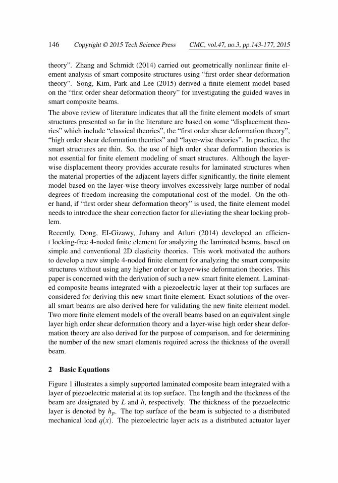
Figure 1 illustrates a simply supported laminated composite beam integrated with alayer of piezoelectric material at its top surface. The length and the thickness of thebeam are designated by L and h, respectively. The thickness of the piezoelectriclayer is denoted by hp. The top surface of the beam is subjected to a distributedmechanical load q(x). The piezoelectric layer acts as a distributed actuator layer
Simple Efficient Smart Finite Elements 147
Figure 1: Schematic diagram of a simply supported laminated composite beamintegrated with a piezoelectric actuator layer.
of the substrate beam. For actuating the substrate beam, the distributed electricpotential (voltage) is applied on the top surface of the piezoelectric layer whilethe surface of the piezoelectric layer being in contact with the top surface of thesubstrate beam is grounded. The origin of the coordinate system (x− z) is locatedat one end of the beam such that the lines given by x = 0 and x = L representthe ends of the beam and the plane given by z = 0 denotes the mid-plane of thebeam. The constitutive relations for the converse and the direct piezoelectric effectsappropriate for the beam analysis are given by
{σ p}= [Cp]{∈p∗}− [e](E}, (1)
{D}= [e]T{∈p∗}+[ε](E} (2)
In Eqs. (1) and (2), the state of stresses {σ p}, the state of assumed strains {∈p∗},the electric field vector {E}, the electric displacement vector {D}, the elastic coef-ficient matrix [Cp], the piezoelectric constant matrix [e] and the dielectric constantmatrix [ε] are given by
{σ p}= [ σpx σ
pz σ
pxz ]T , {∈p∗}= [ ∈p∗
x ∈p∗z γ
p∗xz ]T ,
{E}=[
Ex Ez]T
, {D}=[
Dx Dz]T
,
[Cp] =
Cp11 Cp
13 0Cp
13 Cp33 0
0 0 Cp55
, [e] =
0 e310 e330 0
and [ε] =
[ε11 00 ε33
](3)
148 Copyright © 2015 Tech Science Press CMC, vol.47, no.3, pp.143-177, 2015
in which, σpx , σ
pz and σ
pxz are the normal stress along the x-direction, the normal
stress along the z-direction and the transverse shear stress, respectively at any pointin the piezoelectric layer; while ∈p∗
x , ∈p∗z and γ
p∗xz are the assumed normal strain
along the x-direction, the assumed normal strain along the z-direction and the as-sumed transverse shear strain, respectively at the same point. Also, Cp
i j, ei j and εi j
are the elastic coefficients, the piezoelectric coefficients and the dielectric constantsof the piezoelectric material, respectively while Ex and Ez are the electric fields a-long the x-and the z- directions, respectively. The constitutive relations for the k-thorthotropic composite layer of the substrate beam are
σkx =Ck
11 ∈∗x +Ck13 ∈∗z , σ
kz =Ck
13 ∈∗x +Ck33 ∈∗z
and σkxz =Ck
55γ∗xz, k = 1, 2, 3, . . . , N
(4)
in which, σ kx , σ k
z and σ kxz are the normal stress along the x-direction, the normal
stress along the z-direction and the transverse shear stress, respectively at any pointin the k-th layer of the substrate beam while ∈∗x , ∈∗z and γ∗xz are the assumed normalstrain along the x-direction, the assumed normal strain along the z-direction andthe assumed transverse shear strain, respectively at the same point in the k-th layer.Also, Ck
i j is the elastic constant of the orthotropic k-th layer. The displacementfields {dp} and {d} at any point in the piezoelectric layer and in the substratebeam, respectively are given by
{dp}=[
up wp]T and {d}=
[u w
]T (5)
where up and wp are the displacements at any point in the piezoelectric layer alongthe x-and the z- directions, respectively while u and w are the same in the substratebeam. Based on the displacement fields, the states of strains {∈p} and {∈} at anypoint in the piezoelectric layer and in the substrate beam, respectively are given by
{∈p}=[∈p
x ∈pz γ
pxz]T
=[
∂up
∂x∂wp
∂ z∂up
∂ z + ∂wp
∂x
]T
and {∈}=[∈x ∈z γxz
]T=[
∂u∂x
∂w∂ z
∂u∂ z +
∂w∂x
]T (6)
The electric potential function φ (x, z) at any point in the piezoelectric layer is re-lated to the electric fields as follows:[
Ex Ez]=−
[∂φ
∂x∂φ
∂ z
](7)
The total potential energy (Π) of the overall smart composite beam of width b is
Simple Efficient Smart Finite Elements 149
given by
Π =12
bL∫
0
h/2+hp∫h/2
(σ px ∈p∗
x +σpz ∈p∗
z +σpxzγ
p∗xz −DxEx−DzEz)dz
+N
∑k=1
hk+1∫hk
(σ kx ∈∗x +σ
kz ∈∗z +σ
kxzγ∗xz)dz−2q(x)w(x, h/2+hp)
− 2Φ(x) σ̄(x)|z=h/2+hp
]dx
(8)
In Eq. (8), Φ(x) and σ̄(x)are the applied distributed electric potential and charge onthe top surface of the piezoelectric layer, respectively. Also, hk and hk+1 representthe z coordinates of the bottom and the top surfaces of any orthotropic layer of thesubstrate beam, respectively.
2.1 Derivation of new 4-noded smart finite elements
(a) (b)
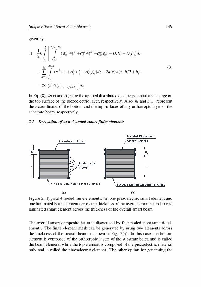
Figure 2: Typical 4-noded finite elements: (a) one piezoelectric smart element andone laminated beam element across the thickness of the overall smart beam (b) onelaminated smart element across the thickness of the overall smart beam
The overall smart composite beam is discretized by four noded isoparametric el-ements. The finite element mesh can be generated by using two elements acrossthe thickness of the overall beam as shown in Fig. 2(a). In this case, the bottomelement is composed of the orthotropic layers of the substrate beam and is calledthe beam element, while the top element is composed of the piezoelectric materialonly and is called the piezoelectric element. The other option for generating the
150 Copyright © 2015 Tech Science Press CMC, vol.47, no.3, pp.143-177, 2015
mesh is to use one element across the thickness of the overall beam as shown inFig. 2(b). This element is a laminated smart finite element in which the top layer isthe piezoelectric layer while the other layers are the orthotropic layers of the sub-strate beam. Thus three types of elements namely the piezoelectric smart element,laminated smart finite element and the beam element are to be formulated for themesh described by Fig. 2. The piezoelectric smart element is characterized by itsheight hp and length L/n with n being the number of elements along the length ofthe beam. The length and height of the beam element are L/n and h, respectively.The assumed strain fields in the piezoelectric and the beam elements are given by[Dong, EI-Gizawy, Juhany and Atluri (2014)]:
{∈p∗}= [A]{γ p} and {∈∗}= [A]{γ} (9)
in which {γ p} and {γ} are the matrices of unknown constants for the assumedstrain distributions and [A] is a matrix describing the distribution of the assumedstrains in the elements. These are given by
[A] =
1 0 0 z 00 1 0 0 x0 0 1 0 0
, {γ p}=[
γp1 γ
p2 γ
p3 γ
p4 γ
p5
]Tand {γ}=
[γ1 γ2 γ3 γ4 γ5
]T (10)
It may be noted from Eqs. (9) and (10) that the assumed normal strains vary linearlywith respect to the element-local Cartesian coordinates and the assumed transverseshear strain is constant. It is also to be noted that the assumed bending strain is notcoupled with the shear deformation. On the other hand, the displacements at anypoint in the respective element are given by nodal interpolation:
{dp}= [N]{dpe} and {d}= [N]{de} (11)
in which [N] is the shape function matrix, {dpe} and {de} are the nodal displace-ment degrees of freedom for the piezoelectric element and the beam element, re-spectively and their explicit forms are as follows:
{dpe}=[
up1 wp
1 up2 wp
2 up3 wp
3 up4 wp
4
]T,
{de}=[
u1 w1 u2 w2 u3 w3 u4 w4]T
,
[N] =
[n1 0 n2 0 n3 0 n4 00 n1 0 n2 0 n3 0 n4
],
n1 = (1−ξ )(1−η)/4, n2 = (1+ξ )(1−η)/4,
n3 = (1+ξ )(1+η)/4 and n4 = (1−ξ )(1+η)/4
(12)

Simple Efficient Smart Finite Elements 151
Figure 3: 4-noded element with five points of collocation.
where upi , wp
i (i=1, 2, 3, 4) are the displacements of the i-th node of the piezoelectricelement along the x-and the z- directions, respectively; ui, wi (i=1, 2, 3, 4) are thesame for the beam element, ni is the shape function of natural coordinates (ξ , η)associated with the i-th node of the element. It is evident from Eqs. (11) and (12)that the mesh based normal strains are associated with the mesh based shear strain.Thus it is impossible to cause linearly varying bending strain across the thicknessof the beam without causing transverse shear strain. This leads to the so-calledphenomenon of shear locking. In order to alleviate this locking problem, Dongand Atluri (2011) suggested to invoke the compatibility between the independentlyassumed strain and the mesh based strain field based on the displacement field atsome pre-selected points of collocation resulting in the solutions of the unknownconstants {γ p} and {γ}. The five such preselected points of collocation as shownin Fig. 3 are considered as follows:
Point A: ξ = 0, η =− 1√3
; Point B: ξ = 0, η =1√3
;
Point C: ξ =− 1√3, η = 0; Point D: ξ =
1√3, η = 0;
Point E: ξ = 0, η = 0;
(13)
Thus the compatibility of the assumed strains with the mesh based strains based onthe displacement fields at the above mentioned five points given by Eq. (13) resultsin the following conditions:

152 Copyright © 2015 Tech Science Press CMC, vol.47, no.3, pp.143-177, 2015
Piezoelectric element:
γp1 + zp
Aγp4 =∈p
x(xp
A,zpA
), γ
p1 + zp
Bγp4 =∈p
x(xp
B,zpB
),
γp2 + xp
Cγp5 =∈p
z(xp
C,zpC
), γ
p2 + xp
Dγp5 =∈p
z(xp
D,zpD
)and γ
p3 = γ
pxz(xp
E ,zpE
) (14)
Beam element:
γ1 + zAγ4 =∈x(xp
A,zpA
), γ1 + zBγ4 =∈x
(xp
B,zpB
),
γ2 + xCγ5 =∈z(xp
C,zpC
), γ2 + xDγ5 =∈z
(xp
D,zpD
)and γ3 = γxz
(xp
E ,zpE
) (15)
It may be noted that the coordinates xpC, xp
D, zpA and zp
B are the local Cartesian co-ordinates of the points of collocation in the piezoelectric element while xC, xD, zA
and zB are the local Cartesian coordinates in the beam element. Using the strain-displacement relations given by Eq. (6) in Eqs. (14) and (15), the unknown con-stants {γ p} and {γ} can be determined as follows:
{γ p}= [X̄ p]−1[B]{dpe}and {γ}= [X̄ ]−1[B]{de} (16)
where,
[X̄ p] =
1 0 0 zp
A 01 0 0 zp
B 00 1 0 0 xp
C0 1 0 0 xp
D0 0 1 0 0
, [X̄ ] =
1 0 0 zA 01 0 0 zB 00 1 0 0 xC
0 1 0 0 xD
0 0 1 0 0
and [B] =
∂n1∂x
∣∣∣A
0 ∂n2∂x
∣∣∣A
0 ∂n3∂x
∣∣∣A
0 ∂n4∂x
∣∣∣A
0∂n1∂x
∣∣∣B
0 ∂n2∂x
∣∣∣B
0 ∂n3∂x
∣∣∣B
0 ∂n4∂x
∣∣∣B
0
0 ∂n1∂ z
∣∣∣C
0 ∂n2∂ z
∣∣∣C
0 ∂n3∂ z
∣∣∣C
0 ∂n4∂ z
∣∣∣C
0 ∂n1∂ z
∣∣∣D
0 ∂n2∂ z
∣∣∣D
0 ∂n3∂ z
∣∣∣D
0 ∂n4∂ z
∣∣∣D
∂n1∂ z
∣∣∣E
∂n1∂x
∣∣∣E
∂n2∂ z
∣∣∣E
∂n2∂x
∣∣∣E
∂n3∂ z
∣∣∣E
∂n3∂x
∣∣∣E
∂n4∂ z
∣∣∣E
∂n4∂x
∣∣∣E
(17)
It may again be noted that each row of the matrix [B] is to be computed at eachof the five collocated points given by Eq. (13). On substitution of Eq. (16) intoEq. (9), the assumed strains can be expressed in terms of the nodal displacementdegrees of freedom as follows:
{∈p∗}= [B∗p]{dpe} and {∈p}= [B∗]{de} (18)
Simple Efficient Smart Finite Elements 153
in which [B∗p] = [A][X̄p]−1[B] and [B∗] = [A][X̄ ]−1[B]. The electric potential at any
point in the piezoelectric finite element can be expressed in terms of the nodalelectric potential degrees of freedom {φ e} as follows:
φ = [Nφ ]{φ e} (19)
where
[Nφ ] =[
n1 n2 n3 n4]
and {φ e}=[
φ1 φ2 φ3 φ4]T (20)
Using Eq. (5) in Eq. (3), it can be written that
{E] =−[Bφ ]{φ e} (21)
where
[Bφ ] =
[∂n1∂x
∂n2∂x
∂n3∂x
∂n4∂x
∂n1∂ z
∂n2∂ z
∂n3∂ z
∂n4∂ z
](22)
The materials being studied here are linear. Thus substituting Eqs. (1), (2), (4),(11), (18), (5) and (6) in Eq. (4) and subsequently applying the principle of mini-mum potential energy i.e. δΠ = 0, the following elemental governing equilibriumequations are obtained:
[K pe]{dpe}+[K pedφ]{φ e}= 0, [K pe
dφ]T{dpe}− [K pe
φφ]{φ e}= {Fe
φ }
and [Ke]{de}= {Fe}(23)
where [K pe] and [Ke] are the elemental stiffness matrices for the piezoelectric ele-ment and the substrate beam element, respectively; [K pe
dφ] and [K pe
φφ] are the elemen-
tal electro-elastic coupling matrix and the elemental dielectric stiffness matrix ofthe piezoelectric layer, respectively. Also, {Fe
φ} and {Fe} are the elemental electri-
cal load vector due to the applied distributed charge and the elemental mechanicalload vector, respectively. The forms of these matrices are given by
[K pe] =
Le∫0
h/2+hp∫h/2
[B∗]T [Cp][B∗]dzdx, [K pedφ] =
Le∫0
h/2+hp∫h/2
[B∗]T [e][Bφ ]dzdx,
[K peφφ] =
Le∫0
h/2+hp∫h/2
[Bφ ]T [ε][Bφ ]dzdx, {Fe
φ }=Le∫
0
[Nφ ]T
σ̄(x, h/2+hp)dx,
[Ke] =
Le∫0
N
∑k=1
hk+1∫hk
[B∗]T [Ck][B∗]dzdx, {Fe}=Le∫
0
[N]T [ 0 1]T p(x,−h/2)dx
154 Copyright © 2015 Tech Science Press CMC, vol.47, no.3, pp.143-177, 2015
(24)
As discussed in [Dong, EI-Gizawy, Juhany and Atluri (2014)], the technique of“over integration” is needed to accurately evaluate the stiffness matrices of laminat-ed elements. In order to take care of the different material properties of each laminain the substrate, a layer-wise two-point Gauss quadrature in the thickness directionis adopted in this study. In this way, we consider another variable (−1 ≤ ηk ≤ 1)as the natural coordinate in the thickness direction of any (k-th) individual layer,which can be related to the natural coordinate (−1 ≤ η ≤ 1) of the whole beamelement as follows:
η =1h(hk +hk+1)+
ηk
h(hk+1−hk) (25)
Thus the elemental stiffness matrix for the substrate beam is to be evaluated as:
[Ke] =
1∫−1
N
∑k=1
1∫−1
[B∗]T [Ck][B∗] |J| (hk+1−hk)
hdηkdξ (26)
The elemental equations as derived above are assembled in a straight forward man-ner to obtain the global equations of equilibrium as follows:
[K]{d}+[Kdφ ]{φ}= {F} (27)
[Kdφ ]T{d}− [Kφφ ]{φ}= {Fφ} (28)
It may be noted that although two sets of equations given by Eqs. (27) and (28)are derived, Eq. (27) is required to compute the nodal displacements if the electricpotential is prescribed and Eq. (28) estimates the corresponding nodal charges.
2.2 Exact Solutions of the Smart Composite Beam
Replacing the assumed strains {∈p∗} and {∈p∗} by the displacement field based s-trains {∈p} and {∈}, respectively in Eq. (8) and applying the principle of minimumpotential energy i.e. δΠ = 0, the following governing equilibrium equations for thepiezoelectric layer and the orthotropic layers of the substrate beam are obtained:
Piezoelectric layer: σpx, x + σ
pxz, z = 0, σ
pxz, x + σ
pz, z = 0 and Dx ,x + Dz ,z = 0 (29)
Substrate beam: σkx,x + σ
kxz,z = 0 and σ
kxz,x + σ
kz,z = 0; k = 1,2,3, ...,N (30)
The simply supported boundary conditions obtained from the variational principleare
σkx = wk = σ
px = wp = φ = 0 at x = 0 and L; k = 1,2,3, ...,N
σpz (x, h/2+hp) = q(x), σ
1z (x,−h/2) = σ
pxz(x, h/2+h f ) = σ
1xz(x,−h/2) = 0,
φ(x, y, h/2+hp) = Φ(x) and φ(x, y, h/2) = 0

Simple Efficient Smart Finite Elements 155
(31)
Also, the variational principle yields the following interface continuity conditions:
up(x, h/2) = uN(x, h/2), wp(x, h/2) = wN(x, h/2),
σpz (x, h/2) = σ
Nz (x, h/2), σ
pxz(x, h/2) = σ
Nxz(x, h/2),
uk(x, hk+1) = uk+1(x, hk+1),
wk(x, hk+1) = wk+1(x, hk+1); k = 1,2,3, ...,N−1
σkz (x, hk+1) = σ
k+1z (x, hk+1),
σkxz(x, hk+1) = σ
k+1xz (x, hk+1); k = 1,2,3, ...,N−1
(32)
2.2.1 Exact solutions for the piezoelectric layer
For a particular mode of deformation, the displacement functions and the electricpotential function for the piezoelectric solid which satisfy the boundary conditionsat the edges of the beam given by Eq. (31) are assumed as
up =U p(z)cos px, wp =W p(z)sin px and φ = Φ(z)sin px (33)
where U p(z), W p(z) and Φ(z) are unknown functions of z and p = mπ/L with mbeing the mode number. It may further be assumed that[
U p(z) W p(z) Φ(z)]=[
U0p W 0p Φ0]
esz (34)
where U0p, W 0p and Φ0 are unknown constants to be determined and s is a char-acteristic parameter. Considering {∈p} and {∈} in place of {∈p∗} and {∈p∗},respectively and subsequently using Eqs. (1), (2), (6), (33) and (34) into the gov-erning equations given by Eq. (29), the following set of homogeneous algebraicequations are obtained: A11 A12 A13−A12 A22 A23−A13 A23 −A33
U0p
W 0p
Φ0
=
000
(35)
in which
A11 =Cp55s2−Cp
11 p2, A12 = (Cp13 +Cp
55)ps, A13 = e31 ps,
A22 =Cp33s2−Cp
55 p2, A23 = e33s2, A33 = ε33s2− ε11 p2 (36)
For non-trivial solutions of U0p, W 0p and Φ0, the determinant of the co-efficientmatrix of Eq. (36) must vanish. This leads to the following sixth degree polynomialequation:
As6 +Bs4 +Cs2 +D = 0 (37)
156 Copyright © 2015 Tech Science Press CMC, vol.47, no.3, pp.143-177, 2015
where,
A = ε33Cp33Cp
55 + e233Cp
55, D =−ε11Cp11Cp
55 p6
B =−{ε33(Cp55
2+Cp
11Cp33)+ ε11Cp
33Cp55− ε33(C
p13 +Cp
55)2
+ e233Cp
11 + e231Cp
33−2e31e33(Cp13 +Cp
55}p2,
C = {ε33Cp11Cp
55 + ε11(Cp55
2+Cp
11Cp33)+ e2
31Cp55− ε11(C
p13 +Cp
55)2}p4 (38)
For the geometrical parameters and material properties of the piezoelectric materialthat is considered for evaluating the numerical results, two real roots and two pairsof complex conjugate roots of Eq. (37) are obtained and these are denoted as
s1 , s2 = ±γ, s3 , s4 = (α± iβ ), s5 , s6 = −(α∓ iβ ) (39)
The last two equations of Eq. (35) provide:
W 0 = f (s)U0 and Φ0 = g(s)U0 (40)
in which,
f (s) =A13A23 +A12A33
A223 +A22A33
, g(s) =A12A23−A13A22
A223 +A22A33
(41)
Now using the roots of Eq. (37) and the relations given by Eq. (40) in Eqs. (33)and (34), the exact solutions for the displacement fields (up, wp) and the electricpotential function (φ ) in the piezoelectric layer are derived as follows:
up =(U1eγz +U2e−γz +U3eαz cos β z+U4eαz sin β z+U5e−αz cos β z
+U6e−αz sin β z) cos px(42)
wp ={R1U1eγz +R2U2e−γz +U3eαz(R3 cos β z−R4 sin β z)
+U4eαz(R4 cos β z+R3 sin β z)−U5e−αz(R3 cos β z+R4 sin β z)
+U6e−αz(R4 cos β z−R3 sin β z)} sin px
(43)
φ ={Q1U1eγz +Q2U2e−γz +U3eαz(Q3 cos β z−Q4 sin β z)
+U4eαz(Q4 cos β z+Q3 sin β z)−U5e−αz(Q3 cos β z+Q4 sin β z)
+U6e−αz(Q4 cos β z−Q3 sin β z)} sin px
(44)
in which Ui (i=1, 2, 3, . ., 6) are the unknown constants. The various constantsappearing in Eqs. (43) and (44) are given by
Ri = f (si) and Qi = g(si); i = 1 and 2
R3 = Re{ f (s3)}, R4 = Im{ f (s3)}, Q3 = Re{g(s3)}and Q4 = Im{g(s4)}
(45)

Simple Efficient Smart Finite Elements 157
Next, using the constitutive relations given by Eq. (1), the exact solutions for thestresses in the piezoelectric layer are obtained as follows:
σpx ={T1U1eγz +T2U2e−γz +U3eαz(T3 cos β z−T4 sin β z)
+U4eαz(T4 cos β z+T3 sin β z)+U5e−αz(T3 cos β z+T4 sin β z)
−U6e−αz(T4 cos β z−T3 sin β z)} sin px
(46)
σpz ={T5U1eγz +T6U2e−γz +U3eαz(T7 cos β z−T8 sin β z)
+U4eαz(T8 cos β z+T7 sin β z)+U5e−αz(T7 cos β z+T8 sin β z)
−U6e−αz(T8 cos β z−T7 sin β z)} sin px
(47)
σpxz ={T9U1eγz +T10U2e−γz +U3eαz(T11 cos β z−T12 sin β z)
+U4eαz(T12 cos β z+T11 sin β z)−U5e−αz(T11 cos β z+T12 sin β z)
+U6e−αz(T12 cos β z−T11 sin β z)} cos px
(48)
The various coefficients Ti (i=1, 2, 3, . . ., 12) appearing in Eqs. (46) to (48) aregiven by
T1 =−pCp11 +R1γCp
13−Q1γe33, T2 =−pCp11−R2γCp
13−Q2γe33,
T3 =−pCp11 +Cp
13(αR3−βR4)+ e33(αQ3−βQ4),
T4 =Cp13(αR4 +βR3)+ e33(αQ4 +βQ3),
T5 =−pCp13 +R1γCp
33 +Q1γe33, T6 =−pCp13−R2γCp
33−Q2γe33,
T7 =−pCp13 +Cp
33(αR3−βR4)+ e33(αQ3−βQ4),
T8 =Cp33(αR4 +βR3)+ e33(αQ4−βQ3),
T9 =Cp55(γ + pR1), T10 =Cp
55(γ− pR2),
T11 =Cp55(α + pR3), T12 =Cp
55(β + pR4) (49)
2.2.2 Exact Solutions for the substrate Beam
For a particular mode of deformation, the displacement field for any (k-th) layerof the substrate beam satisfying the boundary conditions given by Eq. (31) can beassumed as
uk =U0kerkz cos px and wk =W 0kerkz sin px (50)
in which U0k, W 0k are the unknown constants for the k-th layer and ris a character-istic parameter. Substitution of Eq. (50) into the governing equations for the k-th
158 Copyright © 2015 Tech Science Press CMC, vol.47, no.3, pp.143-177, 2015
layer of the substrate beam given by Eq. (30) and the use of strain displacementrelations result into the following characteristics equation for the layer:
Akr4k +Bkr2
k +Ck = 0 (51)
where Ak =Ck33Ck
55, Bk =Ck13
2+2Ck
13Ck55−Ck
11Ck33 and Ck =Ck
11Ck55 p4.
The roots of Eq. (51) are given by
rk1, rk2 = λk, −λk and rk3, rk4 = δk, −δk (52)
where λk =
√1
2Ak
{−Bk +
√B2
k−4AkCk
}and δk =
√1
2Ak
{−Bk−
√B2
k−4AkCk
}Using Eqs. (4), (50) and (52) and carrying out some algebraic manipulations, theexact solutions for the displacement fileds and the state of stresses at any point inthe k-th layer of the substrate beam can be derived as follows:
uk = (Uk1 eλkz +Uk
2 e−λkz +Uk3 eδkz +Uk
4 e−δkz)cos px (53)
wk = {Lk1(U
k1 eλkz−Uk
2 e−λkz)+Lk2(U
k3 eδkz−Uk
4 e−δkz)}sin px (54)
σkx ={(−pCk
11 +Lk1λkCk
13)(Uk1 eλkz +Uk
2 e−λkz)
+(−pCk11 +Lk
2λkCk13)(U
k3 eδkz +Uk
4 e−δkz)}sin px(55)
σkz ={(−pCk
13 +Lk1λkCk
33)(Uk1 eλkz +Uk
2 e−λkz)
+(−pCk13 +Lk
2λkCk33)(U
k3 eδkz +Uk
4 e−δkz)}sin px(56)
σkxz =Ck
55{(λk + pLk1)(U
k1 eλkz−Uk
2 e−λkz)
+(δk + pLk2)(U
k3 eδkz−Uk
4 e−δkz)}cos px(57)
in which Lk1 =
(Ck13+Ck
55)pλk
Ck33λ 2
k−Ck55 p2 and Lk
2 =(Ck
13+Ck55)pδk
Ck33δ 2
k−Ck55 p2 .
2.2.3 Solutions of unknown constants
In order to solve the unknown constants (Ui, i = 1,2,3, ..6;Uki , i = 1,2,3,4 and k =
1,2,3, ...,N), the prescribed boundary conditions are considered as follows:
q(x) = q0 sin px, Φ(x) =V sin px and φ (x, h/2) = 0 (58)
in which q0 is the amplitude of the prescribed mechanical load and V is the am-plitude of the prescribed electric potential at the top surface of the piezoelectriclayer. Satisfaction of the prescribed boundary conditions given by Eqs. (31) and
Simple Efficient Smart Finite Elements 159
(58) and the continuity conditions given by Eq. (32) leads to the following systemof algebraic equations:
[K]{Γ}= {Q} (59)
in which Ki j is the coefficient of Γ j while the vectors {Γ} and {Q} are given by
{Γ}=[
U1 U2 U3 · · · U11 U1
2 U13 U1
4 · · · UN1 UN
2 UN3 UN
4
]Tand {Q}=
[q0 0 V 0 · · · 0 0 0
]T(60)
3 Finite element model using LHSDT
For the beam analysis, an equivalent single layer high order shear deformationtheory (HSDT) proposed by Lo, Christensen and Wu (1978) is given by
u = u0 + zθx + z2φx + z3
γx and w = w0 + zθz + z2φz (61)
in which u0 and w0 are the translational displacement of any point on the mid-plane (z=0) of the substrate beam along x and z directions, respectively; θx and θz
are the first order rotational variables while φx, γx and φz are high order rotationalvariables. In this section, a finite element model of the overall smart beam beingstudied here is derived using a “layer-wise high-order shear deformation theory(LHSDT)”. According to this LHSDT, the displacement field at any point in thesubstrate beam is given by Eq. (61) while the displacement field at any point in thepiezoelectric layer is considered as follows:
up = u0 +h2
θx +h2
4φx +
h3
8γx +(z−h/2)ψx +(z2− h2
4)lx +(z3− h3
8)mx
up = u0 +h2
θz +h2
4φz +(z−h/2)ψz +(z2− h2
4)lz (62)
in which ψx, lx, mx, ψz and lz are the generalized rotational coordinates for thepiezoelectric layer. The generalized displacement coordinates at any point in theoverall beam are expressed in a vector form as follows:
{d}= [ u0 w0 θx φx γx ψx lx mx θz φz ψz lz]T (63)
A three-noded bar element is used for implementing this LHSDT to discretize theoverall beam. Thus the generalized displacement coordinate vector for the i-th nodeof the element is given by
{di}= [ u0i w0i θxi φxi γxi ψxi lxi mxi θzi φzi ψzi lzi]T, i = 1,2,3 (64)
160 Copyright © 2015 Tech Science Press CMC, vol.47, no.3, pp.143-177, 2015
and the generalized displacement vector {d} at any point in the element can beexpressed in terms of the nodal generalized displacement vector as follows:
{d}= [N]{de} (65)
in which the shape function matrix [N] and the nodal generalized displacementvector {de} for the element are given by
[N] =[[N1] [N2] [N3]
]and {de}=
[{d1}T {d2}T {d3}T
]T (66)
while [Ni] = niI with ni and I being the shape function associate with the i-th nodeof the element and a (12x12) identity matrix, respectively. The state of strains atany point in the substrate beam and that in the piezoelectric layer of the elementcan be expressed in terms of the nodal generalized degrees of freedom as follows:
{∈}= [Z1][B1]{de} and {∈p}= [Z2][B2]{de} (67)
in which the matrices [Z1] and [Z2] and the nodal strain-displacement matrices [B1]and [B2] are presented in the Appendix. The electric potential function which iszero at the interface between the piezoelectric layer and the substrate beam may beassumed as
φ(x, z) =(z−h/2)
hpφ0(x) (68)
wherein φ0 is the electric potential distribution at the top surface of the piezoelec-tric layer and can be expressed in terms of the nodal electric potential degrees offreedom {φ e}as follows:
φ0 = [N̄φ ]{φ e}, [N̄φ ] = [ n1 n2 n3 ] and {φ e}= [ φ01 φ02 φ03 ]T (69)
Using Eqs. (7), (68) and (69), the electric filed vector at any point in the piezoelec-tric layer of the element can expressed as
{E}=−[Zp][B3]{φ e} (70)
in which the matrices [Zp]and [B3] are presented in the Appendix. Using Eqs. (8),(65), (67), (69) and (70) and carrying out the explicit integration with respect to z,
Simple Efficient Smart Finite Elements 161
the total potential energy of a typical element can be expressed as follows:
Πe=
12
bLe∫
0
{de}T([B1]
T [D1][B1]+ [B2]T [D2][B2]
){de}dx
+bLe∫
0
{de}T [B2]T [D3][B3]{ϕe}dx
− 12
bLe∫
0
{ϕe}T [B3]T [D4][B3]{ϕe}dx−b{ϕe}T{Fe
ϕ}−b{de}T{Fe}
(71)
in which,
[D1] =N
∑k=1
hk+1∫hk
[Z1]T [Ck][Z1]dz, [D2] =
h/2+hp∫h/2
[Z2]T [Cp][Z2]dz,
[D3] =
h/2+hp∫h/2
[Z2]T [e][Zp]dz [D4] =
h/2+hp∫h/2
[Zp]T [ε][Zp]dz,
{Feφ }=
Le∫0
[Nφ ]T
σ̄dx
and
{Fe}=Le∫
0
[NT] [ 0 1 0 0 0 0 0 0 0 0 0 0 ]T pdx
Now applying the principle of minimum potential energy i.e. δΠ= 0, the followingelemental governing equilibrium equations of the overall smart beam based on theLHSDT are obtained:
[Ke]{dpe}+[Kedφ ]{φ e}= {Fe} and [Ke
dφ ]T{de}+[Ke
φφ ]{φ e}= {Feφ } (72)
In Eq. (72), the various elemental matrices are given by
[Ke] =
Le∫0
([B1]T [D1][B1]+ [B1]
T [D1][B1])dx, [Kedφ ] =
Le∫0
[B2]T [D3][B3]dx
and [Keφφ ] =
Le∫0
[B3]T [D4][B3]dx
(73)

162 Copyright © 2015 Tech Science Press CMC, vol.47, no.3, pp.143-177, 2015
The global equations of equilibrium of the overall smart beam are obtained by as-sembling the elemental equations in a straight forward manner. However, they canbe representd by Eqs. (27) and (28). Using the “equivalent single layer HSDT”given by Eq. (61), the above finite element model (FEM) has been suitably aug-mented to derive another FEM of the overall smart beam. However, for the sake ofbrevity the derivation of this FEM is not presented here.
4 Computation of transverse shear stress
The bending stress (σx) computed by the finite element models as derived abovecan be utilized to compute the transverse shear stress in the overall smart beams bynumerically integrating the governing equilibrium equation as follows:
σxz =−z∫
−h/2
∂σx
∂xdz (74)
5 Results and discussions
In this section, numerical results are presented to investigate the performance ofthe new 4-noded smart finite elements derived here. The thickness of the substratebeam and that of the piezoelectric layer are considered as 5mm and 250µm, respec-tively, while the aspect ratio (L/h) of the substrate beam is considered as 50. Theelastic and piezoelectric material properties of the piezoelectric layer (PZT5H) areused as follows [Smith and Auld (1991)]:
Cp11 = 151GPa, Cp
13 = 96GPa, Cp33 = 124GPa, Cp
55 = 23GPa,
e31 =−5.1C/m2 and e33 = 27C/m2
The material properties of the orthotropic layers of the substrate beam are used asfollows [Pagano (1970)]:
EL = 172.5GPa, EL/ET = 25, υLT = υT T = 0.25,
GLT = 0.6ET , GT T = 0.2ET
in which the symbols have their usual meaning. The top surface of the overall smartbeam is subjected to the sinusoidally distributed upward mechanical load given byEq. (58) while the value of the amplitude (q0) of the applied load is 50N/m2. Unlessotherwise mentioned, the overall smart beam is discretized considering one elementfor the substrate beam and one piezoelectric finite element across the thickness ofthe overall smart beam as shown in Fig. 2(a). Also 10 elements are considered

Simple Efficient Smart Finite Elements 163
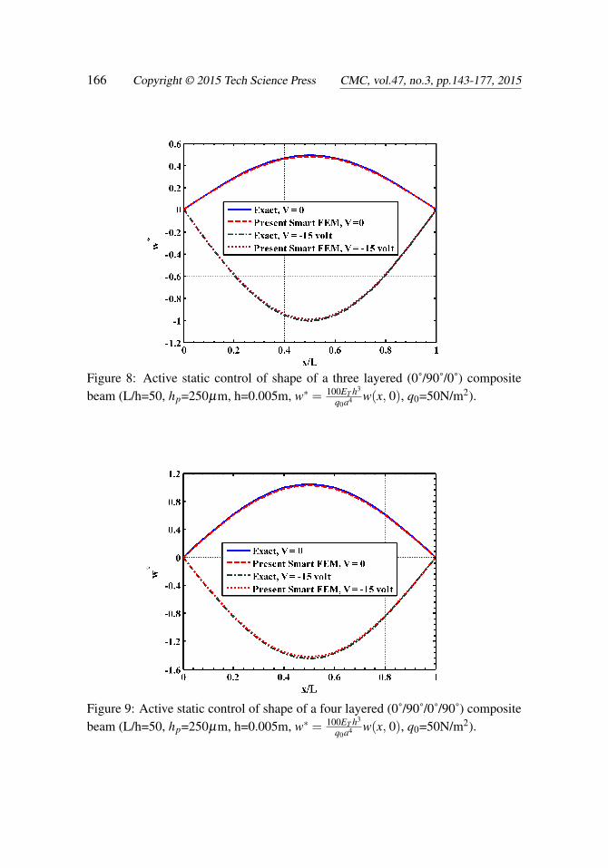
along the length of the beam. First a smart beam is considered in which the sub-strate beam is a single layered beam. Figure 4 illustrates the static responses of thisbeam when the piezoelectric layer is activated with the prescribed electric potential(voltage) on its top surface. Displayed in the figure are the deflections w(x, 0) ofthe mid-plane of the beam computed by the present new smart finite element model(FEM) and exact solutions. It may be observed from this figure that the piezoelec-tric layer activated by a negative voltage counteracts the upward deflection of thebeam due to the mechanical load only. The responses obtained by the present newsmart FEM almost identically match with the exact solutions when the piezoelec-tric layer is passive (V =0) and active (V 6=0). The distributions of the axial normalstress σx(a/2, z) and the transverse shear stress σxz(L/30, z) across the thickness ofthe substrate of this smart beam have been illustrated in Figs. 5 and 6, respectively.It may be observed from these figures that the flexural stress and transverse shearstress computed by the present new FEM match excellently with the exact solu-tions for the flexural stress and the transverse shear stress when the piezoelectriclayer is active (V 6=0) and passive (V =0). Figures 7 to 9 illustrate that the deflec-tions w(x, 0) of the mid-plane of the cross-ply substrate beams when the laminationsequence in the beams are (0˚/90˚), (0˚/90˚/0˚) and (0˚/90˚/0˚/90p), respectively. Itmay be observed from these figures that the present new smart FEM accuratelycomputes the deflections of the mid-plane of these substrate beams. Figures 10 and11 illustrate the comparison of the distributions of the axial normal stress σx(a/2, z)across the thickness of the symmetric (0˚/90˚/0˚) and antisymmetric (0˚/90˚/0˚/90p)cross-ply substrate beams computed by the present new smart FEM with that ob-tained by the exact solutions. It may be observed that the present new smart FEMaccurately computes the bending stress in the multi-layered composite beams whenthe piezoelectric layer is active (V 6=0) and passive (V =0). When compared withthe exact solutions, the transverse shear stress σxz(L/30, z) across the thicknessof the multilayered symmetric (0˚/90˚/0˚) and antisymmetric (0˚/90˚/0˚/90p) cross-ply substrate beams computed by the present new smart FEM are indistinguishablefrom those obtained by the exact solutions as shown in Figs. 12 and 13, respective-ly.
At this juncture it may be recalled that the forgoing results are presented consid-ering one element across the thickness of the substrate beam and one piezoelectricfinite element across the thickness of the piezoelectric layer as shown in Fig. 2(a).Thus two elements are used across the thickness of the overall smart beam. Sincethe beam element contains multiple orthotropic layers, a question naturally aris-es that if one element can be used across the thickness of the overall smart beamin which the top layer of the element is the piezoelectric layer as shown in Fig.2(b). Figure 14 illustrates such results for the deflection of the mid-plane of a

164 Copyright © 2015 Tech Science Press CMC, vol.47, no.3, pp.143-177, 2015
Figure 4: Active static control of shape of a single layered composite beam(L/h=50, hp=250µm, h=0.005m, w∗ = 100ET h3
q0a4 w(x, 0), q0 =50N/m2).
Figure 5: Distribution of axial stress across the thickness of the beam with and with-out actuated by a piezoelectric layer (L/h=50, hp=250µm, h=0.005m, q0 =50N/m2).

Simple Efficient Smart Finite Elements 165
Figure 6: Distribution of the transverse shear stress across the thickness of thesingle layered composite beam (L/h=50, hp=250µm, h=0.005m, q0=50N/m2).
Figure 7: Active static control of shape of a two layered (0˚/90˚) composite beam(L/h=50, hp=250µm, h=0.005m, w∗ = 100ET h3
q0a4 w(x, 0), q0=50N/m2).
166 Copyright © 2015 Tech Science Press CMC, vol.47, no.3, pp.143-177, 2015
Figure 8: Active static control of shape of a three layered (0˚/90˚/0˚) compositebeam (L/h=50, hp=250µm, h=0.005m, w∗ = 100ET h3
q0a4 w(x, 0), q0=50N/m2).
Figure 9: Active static control of shape of a four layered (0˚/90˚/0˚/90˚) compositebeam (L/h=50, hp=250µm, h=0.005m, w∗ = 100ET h3
q0a4 w(x, 0), q0=50N/m2).

Simple Efficient Smart Finite Elements 167
Figure 10: Distribution of the axial stress across the thickness of the three lay-ered (0˚/90˚/0˚) composite beam with and without actuated by a piezoelectric layer(L/h=50, hp=250µm, h=0.005m, q0=50N/m2).
Figure 11: Distribution of the axial stress across the thickness of the four layered(0˚/90˚/0˚/90˚) composite beam with and without actuated by a piezoelectric layer(L/h=50, hp=250µm, h=0.005m, q0=50N/m2).

168 Copyright © 2015 Tech Science Press CMC, vol.47, no.3, pp.143-177, 2015
Figure 12: Distribution of the transverse shear stress across the thickness ofthe three layered (0˚/90˚/0˚) composite beam (L/h=50, hp=250µm, h=0.005m,q0=50N/m2).
Figure 13: Distribution of the transverse shear stress across the thickness ofthe four layered (0˚/90˚/0˚/90˚) composite beam (L/h=50, hp=250µm, h=0.005m,q0=50N/m2).

Simple Efficient Smart Finite Elements 169
Figure 14: Comparisons of the responses due to in-plane actuation (e31 6= 0, e33 =0) and combined in-plane and transverse actuations (e31 6= 0, e33 6= 0) with thoseobtained by the exact solutions considering one element across the thickness of theoverall single layered substrate composite beam (L/h=50, hp=250µm, h=0.005m,w∗ = 100ET h3
q0a4 w(x, 0), q0=50N/m2, V =-15 volt).
Figure 15: Comparison of the FEM based on the HSDT with the present smartFEM for active shape control of a single layered substrate composite beam (L/h=50,hp=250µm, h= 0.005m, w∗ = 100ET h3
q0a4 w(x, 0), q0=50N/m2).

170 Copyright © 2015 Tech Science Press CMC, vol.47, no.3, pp.143-177, 2015
Figure 16: Comparison of the FEM based on the LHSDT with the present smartFEM for the active shape control of a single layered substrate composite beam(L/h=50, hp=250µm, h = 0.005m, q0=50N/m2, w∗ = 100ET h3
q0a4 w(x, 0)).
Figure 17: Active shape control of single layered cantilever substrate compositebeam (L/h=50, hp=250µm, h= 0.005m, q0=50N/m2, w∗ = 100ET h3
q0a4 w(x, 0)).
Simple Efficient Smart Finite Elements 171
single-layered substrate beam when one element is used across the thickness of theoverall beam. It may also be noted that when e31 6=0 and e33 =0, the piezoelectriclayer causes in-plane actuation. On the other hand when e31 6=0 and e33 6=0, thepiezoelectric layer causes both in-plane and transverse actuations simultaneously.Also, if the magnitude of e33 is much larger than that of e31, the transverse actu-ation by the piezoelectric layer will be predominant must be modeled. It may beobserved from Fig. 14 that if the piezoelectric layer acts as the in-plane actua-tor, the responses obtained by the present smart FEM with one element across thethickness of the overall beam excellently match with the exact solutions. If bothin-plane and transverse actuations by the piezoelectric layer are modeled by usingone element across the thickness of the overall beam, the responses of the actuat-ed substrate beam do not match with the exact solutions. This may be attributedto the fact that the transverse displacement continuity at the interface between thepiezoelectric layer and the substrate beam cannot be explicitly satisfied using oneelement across the thickness. But it may again be observed from Fig. 4 that if oneelement for the substrate beam and one piezoelectric finite element for the piezo-electric layer are used across the thickness of the overall beam, the responses due totransverse actuation computed by the present new FEM excellently match with theexact solutions. In order to be confirmed that a separate piezoelectric finite elementis necessary across the thickness of the overall beam for the piezoelectric materialcharacterized with large value of e33, the responses of the overall beam obtained bythe different finite element models based on an equivalent single layer high ordershear deformation theory (HSDT) and a layer-wise high order shear deformationtheory (LHSDT) as derived in Section 3.0 are compared with the exact solutions asshown in Figs. 15 and 16. For the results obtained by the present new smart FEMas displayed in Figs. 15 and 16, two elements are considered across the thicknessof the overall beam. It may be observed from Fig. 15 that the responses obtainedby the FEM based on an equivalent single layer HSDT differ unacceptably fromthat obtained by the present new smart FEM and exact solutions. But the responsesobtained by the FEM based on the LHSDT excellently match with that obtained bythe present new smart FEM and exact solutions as shown in Fig. 16. This ensuresthat at least two elements comprising one element for the substrate beam and oneelement for the piezoelectric layer across the thickness of the overall smart beammust be considered for deriving accurate FEM based on the proposed new method.Also, for the results presented in Fig. 16, the new smart FEM requires 66 degreesof freedom for the beam, whereas the FEM based of the LHSDT requires 492degrees of freedom. Thus the present new smart FEM is computationally muchless costly than the FEM based on the LHSDT. Similar results are also obtainedfor the substrate cross-ply beams with more number of laminae. However, for thesake of brevity they are not presented here. Finally, the deflections of a cantilever

172 Copyright © 2015 Tech Science Press CMC, vol.47, no.3, pp.143-177, 2015
smart beam subjected to uniformly distributed load with intensity q0=50N/m2 andactuated by the piezoelectric layer are presented in Fig. 17. In this case, the piezo-electric layer is subjected to a uniformly distributed applied electric potential at itstop surface. It may be observed from this figure that the responses obtained by thepresent new FEM match excellently with that obtained by the FEM based on theLHSDT. Thus the present new 4-noded smart finite element can be efficiently usedfor accurate modeling of the smart composite beams without using the existinghigher-order deformation theories or layer-wise deformation theories.
6 Conclusions
In this paper, new smart finite elements have been developed for the static analysisof smart laminated composite beams. The smart beam is composed of a laminat-ed substrate composite beam integrated with a piezoelectric layer at its top surfacewhich acts as the distributed actuator of the substrate beam. In case of simplysupported beams, the top surface of the piezoelectric layer is subjected to the sinu-soidally distributed mechanical load and a sinusoidally distributed applied electricpotential. In case of the cantilever beam, the top surface of the piezoelectric layeris subjected to the uniformly distributed mechanical load and electrical potential.For the simply supported smart composite beams, exact solutions are derived tovalidate the proposed new smart finite elements. These smart beams are also mod-eled for comparison purpose by the conventional finite element method using an“equivalent high order shear deformation theory (HSDT)” and a “layer- wise highorder shear deformation theory (LHSDT)”. Several examples are considered forpresenting the numerical results. Two types of new smart finite elements are devel-oped. One is purely piezoelectric called the “piezoelectric element” and is used todiscretize the piezoelectric layer. The other element is a “laminated smart element”in which the top layer is piezoelectric, while the other layers are the orthotropic lay-ers of the substrate beam. The overall smart composite beam has been discretizedby using either two elements or one element across the thickness of the beam. Incase of two elements across the thickness, the top element is the “piezoelectric fi-nite element” and the bottom element is the “laminated beam element” containingonly the orthotropic layers of the substrate beam. When the piezoelectric actuatorlayer is active and passive, and causes both transverse and in-plane actuations, thedeflections, bending stresses and the transverse shear stresses of the smart compos-ite beams computed by the present new smart FEM excellently match with thoseobtained by the exact solutions if two elements are used across the thickness of theoverall beams. If one laminated smart finite element is used across the thicknessof the overall smart composite beams, the transverse actuation by the piezoelectriclayer cannot be accurately modeled. The transverse actuation by the piezoelectric
Simple Efficient Smart Finite Elements 173
layer cannot be accurately modeled even if the overall smart beam is modeled byusing the equivalent single layer HSDT. When the overall smart beam is modeledby using the LHSDT, the responses of the smart composite beams due to bothtransverse and in-plane actuations by the piezoelectric layer excellently match withthose obtained by the exact solutions and the new smart FEM considering two el-ements across the thickness of the beams. This corroborates the fact that in case ofthe piezoelectric actuator that is characterized by the large value of the transversepiezoelectric coefficient (e)33 at least one piezoelectric finite element and one beamelement must be used across the thickness of the overall smart beams for accurate fi-nite element modeling of the smart composite beams. The new smart FEM derivedhere also accurately computes the active and passive responses of the cantileversmart composite beams. As compared to the other FEMs based on the HSDT andthe LHSDT, the effort needed to derive the present new 4-noded smart FEM isnegligible. Also, the present new smart FEM is computationally significantly lesscostly than the FEMs derived by using the HSDT and the LHSDT. The investi-gations carried out here suggests that the present new 4-noded smart finite elementcan be efficiently used for accurate modeling of smart composite beams without us-ing the explicit forms of the displacement fields such as the classical beam theory,the first order and the high order shear deformation theories, the layer-wise theoryand the like.
References
Ahmad, S. N.; Upadhyay, C. S.; Venkatesan, C. (2005): Electroelastic analysisand layer-by-layer modeling of a smart beam. AIAA Journal, vol. 43, no. 12, pp.2606-2612.
Al-Ajmi, M. A.; Benjeddou, A. (2008): Damage indication in smart structuresusing modal effective electromechanical coupling coefficients. Smart Materialsand Structures, vol. 17, art no. 035023.
Bailey, T.; Hubbard, J. E. (1985): Distributed piezoelectric polymer active vibra-tion control of a cantilever beam. AIAA Journal of Guidance and Control, vol. 8,no. 5, pp. 605-611.
Bruke, S. E.; Hubbard, J. E. (1987): Active vibration control of a simply sup-ported beam using a spatially distributed actuator. IEEE Control System Magazine,vol. 8, pp. 25-30.
Bhattacharyya, P.; Suhail, H.; Sinha, P. K. (1998): Finite element free vibrationanalysis of smart laminated composite beams and plates. Journal of IntelligentMaterial Systems and Structures, vol. 9, pp. 20-32.
Bendary, I. M.; Elshafei, M. A.; Riad, A. M. (2010): Finite element model of s-
174 Copyright © 2015 Tech Science Press CMC, vol.47, no.3, pp.143-177, 2015
mart beams with distributed piezoelectric actuators. Journal of Intelligent MaterialSystems and Structures, vol. 21, pp. 747-754.
Crawley, E. F.; Luis, J. D. (1987): Use of piezoelectric actuators as elements ofintelligent structures. AIAA Journal, vol. 27, pp. 1801-1807.
Chee, C. Y. K.; Tong, L.; Steven, G. (1999): A mixed model for composite beamswith piezoelectric actuators and sensors. Smart Materials and Structures, vol. 8,pp. 417-432.
Chee, C.; Tong, L.; Steven, G. P. (2002): Piezoelectric actuator orientation op-timization for static shape control of composite plates. Composite Structures, vol.55, pp. 169-184.
Dong, L.; Atluri, S. N. (2011): A Simple Procedure to Develop Efficient & StableHybrid/Mixed Elements, and Voronoi Cell Finite Elements for Macro- & Microme-chanics. Computers, Materials & Continuum, vol. 24, no. 1, pp. 61-104.
Dong, L.; EI-Gizawy, A. S.; Juhany, K. A.; Atluri, S. N. (2014): A simplelocking-alleviated 4-node mixed-collocation finite element with over-integration,for homogenous or functionally-graded or thick-section laminated compositebeams. Computers, Materials & Continuum, vol. 40, no. 1, pp. 49-77.
Elshafei, M. A.; Alraiess, F. (2013): Modeling and analysis of smart piezoelectricbeams using simple higher order shear deformation theory. Smart Materials andStructures, vol. 22, art no. 035006.
Forward, R. L. (1981): Electronic damping of orthogonal bending modes in acylindrical mast-experimen. Journal of Spacecraft and Rocket, vol. 18, no. 1, pp.11-17.
Gupta, V. K.; Seshu, P.; Issac, K. K. (2004): Finite element and experimentalinvestigation of piezoelectric actuated smart shells. AIAA Journal, vol. 42, pp.2112-2118.
Ha, S. K.; Keilers, C.; Chang, F. K. (1992): Finite element analysis of compositestructures containing distributed piezoceramic sensors and actuators. AIAA journal,vol. 30, no. 3, pp. 772-780.
Hwang, W. S.; Park, C. H. (1993): Finite element modeling of piezoelectric sen-sors and actuators. AIAA journal, vol. 31, no. 5, pp. 930-936.
Im, S.; Atluri, S. N. (1989): Effects of piezoactuator on a finitely deformed beamsubjected to general loading. AIAA Journal, vol. 25, pp. 1373-1385.
Kulkarni, S. A.; Bajoria, K. M. (2003): Finite element modeling of smartplates/shells using higher order shear deformation theory. Composite Structures,vol. 62, pp. 41-50.
Lo, K. H.; Christensen, R. M.; Wu, E. M. (1978): Stress solution determination

Simple Efficient Smart Finite Elements 175
for high order plate theory. International Journal of Solids and Structures, vol. 14,pp. 655-662.
Lin, C.; Hsu, C.; Huang, H. N. (1996): Finite element analysis on deflectioncontrol of plates with piezoelectric actuators. Composite Structures, vol. 35, pp.423-433.
Luo, Q.; Tong, L. (2004): An accurate laminated element for piezoelectric smartbeams including peel stress. Computational Mechanics, vol. 33, pp. 108-120.
Miller, S. E.; Hubbard, J. E. (1987): Obsevability of a Bernouli-Euler beam usingPVF2 as a distributed sensor. MIT Draper Laboratory Report.
Neto, M. A.; Yu, W.; Roy, S. (2009): Two finite elements for general compositebeams with piezoelectric actuators and sensors. Finite Elements in Analysis andDesign, vol. 45, pp. 295-304.
Pagano, N. J. (1970): Exact solutions for rectangular bidirectional composites andsandwich plates. Journal of Composite Materials, vol. 4, pp. 20-34.
Park, H.; Lee, U. (2012): Dynamic analysis of smart composite beams by usingthe frequency-domain spectral elemental method. Journal of Mechanical Scienceand Technology, vol. 26, pp. 2511-2521.
Robbins, D. H.; Reddy, J. N. (1991): Analysis of piezoelectrically actuated beamsusing a layer-wise displacement theory. Computers & Structures, vol. 41, no. 2,pp. 265-279.
Ray, M. C.; Bhattacharyya, R.; Samanta, B. (1994): Static analysis of an intel-ligent structure by the finite element method. Computers and Structures, vol. 52,no. 4, pp. 617-631.
Shi, G.; Atluri, S. N. (1990): Active control of nonlinear dynamic response ofspace-frames using piezo-electric actuators. Computers and Structures, vol. 34,no. 4, pp. 549-564.
Smith, W. A.; Auld, B. A. (1991): Modeling 1-3 composite piezoelectrics: Thick-ness mode oscillations. IEEE Transactions on Ultrasonics, Ferroelectrics and Fre-quency Control, vol. 31, pp. 40–47.
Saravanos, D. A.; Heyliger, P. R. (1995): Coupled layerwise analysis of compos-ite beams with embedded piezoelectric sensors and actuators. Journal of IntelligentMaterial Systems and Structures, vol. 6, pp. 350-362.
Saravanos, D. A.; Hetliger, P. R.; Hopkins, D. A. (1997): Layerwise mechan-ics and finite element for the dynamic analysis of piezoelectric composite plates.International Journal of Solids and Structures, vol. 34, no. 3, pp. 359-378.
Song, Y.; Kim, S.; Park, I.; Lee, U. (2015): Dynamics of two-layer smartcomposite Timoshenko beams: frequency domain spectral element analysis. Thin-

176 Copyright © 2015 Tech Science Press CMC, vol.47, no.3, pp.143-177, 2015
Walled Structures, vol. 89, pp. 84-92.
Trindade, M. A.; Benjeddou, A. (2006): On higher-order modeling of smartbeams with embedded shear-mode piezoceramic actuators and sensors. Mechanicsof Advanced Materials and Structures, vol. 13, pp. 357-369.
Umesh, K.; Ganguli, R. (2011): Composite material and piezoelectric coefficientuncertainty effects on structural health monitoring using feedback control gains asdamage indicators. Structural Health Monitoring, vol. 10, no. 2, pp. 115-129.
Varadarajan, S.; Chandrashekhara, K.; Agarwal, S. (2000): LQG/LTR-basedrobust control of composite beams with piezoelectric devices. Journal of Vibrationand Control, vol. 6, pp. 607-630.
Valoor, M. T.; Chandrashekhara, K.; Agrawal, S. (2001): Self-adaptive vibra-tion control of smart composite beams using recurrent neural architecture. Interna-tional Journal of Solids and Structures, vol. 38, pp. 7857-7874.
Zabihollah, A.; Sedagahti, R.; Ganesan, R. (2007): Active vibration suppressionof smart laminated beams using layerwise theory and an optimal control strategy.Smart Materials and Structures, vol. 16, pp. 2190-2201.
Zhang, S. Q.; Schmidt, R. (2014): Static and dynamic FE analysis of piezoelec-tric integrated thin-walled composite structures with large rotations. CompositeStructures, vol. 112, pp. 345-357.
Appendix
The matrices [Z1], [Z2] and [Zp] appearing in Eqs. (67) and (70) are as follows: 1 z z2 z3 0 0 0 0 00 0 0 0 1 2z 0 0 00 0 0 0 0 0 1 z z2
, 1 h
2h2
4h3
8 z− h2 z2− h2
4 z3− h3
8 0 0 0 0 0 0 0 0 00 0 0 0 0 0 0 1 2z 0 0 0 0 0 0 00 0 0 0 0 0 0 0 0 1 2z 3z2 h
2h2
4 z− h2 z2− h2
4
and
[Zp] =1hp
[z− h
2 00 1
]The nodal strain-displacement matrices [B1] and [B2] are given by
[B1] =[[B11] [B12] [B13]
]and [B2] =
[[B21] [B22] [B23]
]

Simple Efficient Smart Finite Elements 177
The nonzero elements of the submatrices [B1i], i=1, 2, 3 are as follows:
B1i(1,1)=B1i(2,3)=B1i(3,4)=B1i(4,5)=B1i(7,2)=B1i(8,9)=B1i(9,10)=∂ni
∂x,
B1i(5, 9) = B1i(6, 10) = B1i(7, 3) = ni, B1i(8, 4) = 2ni and B1i(9, 5)=3ni
The nonzero elements of the submatrices [B2i], i=1, 2, 3 are as follows:
B2i(1,1)=B2i(2,3)=B2i(3,4)=B2i(4,5)=B1i(5,6)=B2i(6,7)=B1i(7,8)=∂ni
∂x,
B2i(10, 2) = B2i(13, 9) = B2i(14, 10) = B2i(15, 11) = B1i(16, 12) =∂ni
∂x,
B2i(8, 11) = B2i(9, 12) = B2i(10, 6) = B2i(11, 7) = B1i(12, 8) = ni
The nodal electric field-potential matrix [B3] appearing in Eq. (70) is given by
[B3] =
[∂n1∂x
∂n2∂x
∂n3∂x
n1 n2 n3
]