Embed Size (px)
Citation preview

1
Simple Flow Measurement Devices for Open Channels
Seth Davis, Graduate Student
Zohrab Samani, Foreman Professor
Civil Engineering Department, New Mexico State University
June 2016
Funded by New Mexico Water Resources Research Institute

2
Table of Contents
Introduction ........................................................................................................................................... 3
Principles of Flow Measurements in Open Channels ........................................................................... 4
Chapter 1: Simplified Flumes ............................................................................................................... 6
Circular Flumes (Samani and Magallanez, 1992)............................................................................. 8
Design Example of a Circular Flume .......................................................................................... 13
S-M flume (Samani and Magallanez, 2002) .................................................................................... 14
Design Example of an S-M Flume ............................................................................................... 19
Alternate Solutions ...................................................................................................................... 20
Trapezoidal Flumes (Samani and Magallanez, 1993) ..................................................................... 22
Design Example of a Trapezoidal Flume .................................................................................... 27
Alternate solution ........................................................................................................................ 28
General Recommendations ............................................................................................................. 29
Chapter 2: Traditional Flow Measurement Devices .......................................................................... 31
Circular Gate (Turnout) Flow Measurement ................................................................................. 31
Example Calculation of Flow through an Armco Circular Gate ............................................... 33
Traditional Flumes .......................................................................................................................... 33
Parshall Flumes ........................................................................................................................... 34
Cutthroat Flumes ......................................................................................................................... 37
RBC Flumes ................................................................................................................................. 39
Weirs ................................................................................................................................................ 42
Contracted Rectangular Weirs .................................................................................................... 43
Suppressed Rectangular Weirs ................................................................................................... 46
Cipolletti Weirs ............................................................................................................................ 47
V-notch Weirs .............................................................................................................................. 48
References ............................................................................................................................................ 51

3
Introduction
With increasing demands from agriculture, municipal needs, industry, and recreational use, there
is a need for water users to conserve, use, and share water wisely. Measuring water in open
channels is an important first step toward water conservation. The measurement of the amount
of water delivered and received by users will help ensure that each gets their fair share and
establish a more equitable distribution of available water and promote conservation. Ever since
the development of Parshall Flume (Parshall, 1926), continuous improvements have been made
to simplify, reduce cost, increase accuracy, and reduce head losses in open channel flumes
(Hagar, 1988, Skogerboe, 1972, Replogle, 1975, Samani, 1992, 1993, 2000, USBR, 1985).
As we study the importance of water use and management, the importance of knowing not only the
quality, but quantity of water becomes more apparent. Traditional flumes and weirs are practical in many
scenarios, allowing for accurate flow measurement. However, with the low-gradient, high sediment
channels found in many parts of the world coupled with the financial constraints and lack of technical
expertise, there is a need for a simple, cost efficient way to measure discharge. Simple flumes do not
require extensive upstream transition reducing the amount of materials needed and the cost for
construction. They produce minimal head loss and are self flushing and do not accumulate sediment
often found in weirs or even in traditional weirs in low-gradient conditions. Simple flumes have been
found to be an attractive and accurate option to consider when measuring flow.
This manual is divided into two main chapters the first of which outlines the design
characteristics of simple flow measurement devices which are typically easier and less expensive
to produce. The second chapter investigates more traditional flow measurement devices while
outlining the strengths and weaknesses of both types of flumes. Not all flow measuring devices
are suitable for all conditions; the selection of a specific weir or flume often depends on the
hydraulic conditions of the canal and the specific objectives of flow measurement.

4
Principles of Flow Measurements in Open Channels
To understand flow measurement it is necessary to understand how water flows. Water flow is
based on principle of energy. Two types of energy govern flow in open channels, global and
specific energy. According to the principle of specific energy, minimum energy occurs when the
Froude number (Fr) is equal to 1.
22
31
( )
Q TFr
g A (1)
Where:
Q = flowrate
A = cross-sectional area
T = top width of the flow
g = acceleration of gravity
As shown in figure 1.
Figure 1. Typical channel dimensions shown in a channel cross-section.
This condition of minimum energy is also produces a specific flow called critical flow. As can
be seen in equation 1 when critical flow occurs, the flow rate (Q) can be calculated through the
cross-section area and top width of the flow. To accurately measure flow in open channel, it is
y
T
B
1
z
A
5
necessary to create a critical flow condition allowing flow to be measured by simply measuring
the flow depth (yielding values for both T and A).
Critical flow in open channels can be created by three means: 1. Raising the bottom of the
channel; 2. Lowering the bottom of the channel; 3. Contracting the flow cross-section (narrowing
the channel). Flow measurement devices strive to achieve this critical flow for various
conditions thus providing an accurate means of measurement.
6
Chapter 1: Simplified Flumes
Flumes are specially shaped open channel flow sections that are created to constrict flow in a
canal or ditch and induce critical flow, allowing the flow rate to be determined. They are
constructed of metal, concrete, wood, or fiberglass and can measure water over a wide variety of
flow ranges. Larger flumes are constructed on site, while smaller flumes can be prefabricated
and installed later on site.
Simple flumes require relatively little head loss, can operate in flat ditches, are relatively
insensitive to approach velocity, and are self-cleaning due to the high velocity of water passing
through. Flumes must be leveled and the flow entering the flume cannot contain waves or surges
in order to provide accurate flow measurements.
Critical flow can be created by contracting the cross section of an existing canal without
changing the existing canal dimensions. Simple flumes create a small section of critical flow
before water returns to its previous energy state after a hydraulic jump has occurred. Minimal
head loss is required and no extended inflow or outflow transition is needed. These flumes
reduce the cost, calculations, and head loss while minimizing the required materials needed to
measure flow. As canals come in various shapes and sizes, various short throated flumes have
been developed to measure the flow in each respectively. The three simple flume types that have
been developed are circular, rectangular (S-M), and trapezoidal flumes seen in figures 2, 11, and
20.
When the flow cross-section is contracted to create a critical flow, the discharge rate depends on
the upstream energy (H), the width of the critical section (Bc), and the acceleration of gravity (g)
as seen in figures 4 and 5. Therefore flow can be described as a function of H, Bc, and g as:
Q = function(H,Bc, g)
Gravity remains a constant, and the critical section (Bc) can be calculated for each channel type,
leaving the upstream energy (H) as the only variable needed to calculate flow.

7
The function of Q was found to be (Samani, 2016):
(2)
Where:
Q = flowrate, ft3/s or m
3/s
Bc = critical cross section width, ft or m
g = gravity, ft/s2 or m/s
2
H = upstream height of water at flume, ft or m
a and b are empirical coefficients that are determined experimentally using laboratory scale
models shown in table 1 (Samani et al, 1991, 2000, 2003). These values are the same when
using both imperial and metric measuring systems.
Table 1. Coefficients for various short throated flumes fitting the general equation (2).
Once the dimensions of the channel and flume are known, Bc becomes a function of H, making
the upstream height of water (H), the only variable needed to determine discharge.

8
Circular Flumes (Samani and Magallanez, 1992)
Pipes are often used to drain or convey water, and partially full pipes are considered open
channels. The flume created in these circular channels consists of a vertical pipe installed inside
a horizontal circular pipe to create critical flow. Cross-sectional and profile views of the circular
flume are shown in figures 4 and 5. The head or height of the flow would be measured at the
center of the upstream side of the vertical column as indicated by the ruler in figure 2.
Figure 2. Cut out view of a circular flume from the upstream side (Samani, 1991).

9
Figure 3. Circular flume in southern New Mexico irrigation canal, located at GPS coordinates:
32.359167, 106.784722.
Inserting the coefficients for circular flumes from table 1 into equation 2, the equation for
discharge using a circular flume is:
(3)
Where:
Q = discharge, ft3/s or m
3/s
H = head , ft or m
g = gravity, ft/s2 or m/s
2
Bc = width of channel at critical cross section in feet or meters, given by:
(4)

10
Where:
D = inside diameter of horizontal pipe (channel), ft or m
d = outside diameter of vertical pipe, ft or m
For the sake of simplicity, the critical width (Bc) of a channel is defined by D – d with the
coefficients (a,b) being used to correct for the change in critical width that occurs with the
changing height in flow (Hagar, 1988). The parameters described in equations 3 and 4 are
shown in figures 4 and 5.
Figure 4. Cross sectional view of a circular flume.
Figure 5. Profile view of circular flume and flow (Badar, 2012).
d
D

11
The principle limiting factors when designing simple flumes are: 1) the maximum submergence
ratio (Hb/Ha), which is the height of water downstream (Hb) divided by the height of the water
measured at the flume gage (Ha), 2) the ratio of the vertical column (d) to the diameter of the
pipe (D), and 3) the entrance and exit lengths of the flume. Laboratory experiments (Samani,
1992) found the maximum submergence limit to be 0.80 (80%), the minimum ratio of d/D to be
0.25, the minimum entrance length to be equal to or greater than the maximum height of the
water (entrance length ≥ H), and the minimum exit length to be equal to or greater than one half
the maximum height of the water (exit length ≥ ½ H) as seen in figure 6.
Figure 6. Diagram indicating critical design parameters, where Hb/Ha ≤ 0.8 and d/D ≥ 0.25.
One advantage to the circular flume is that it functions similar to v-notch, having a large
exponent (2.31) thus being able to measure a large range of flow. This makes the circular flume
ideal for variable flow conditions. The circular flume has been adopted for use in United States
and various other countries. Some of their applications can be seen in figures 3, 7, 8, and 9.
H 1/2H
Ha
d
Hb
D
Q

12
Figure 7. Circular flume in North Dakota used to measure drainage discharge.
Figure 8. Circular flume in Canada used to measure flow in a canal (Ontkean, 2015).

13
Design Example of a Circular Flume
The following is an example of how to design and calibrate a circular flume for a given channel,
known flow rate, and known normal maximum water depth.
Example:
Existing circular canal with a diameter: 1.2 ft
Maximum flow rate: 1.0 ft3/s
Normal depth at maximum flow: 0.57 ft
We first assume a diameter of the interior vertical flume, generally in pipe sizes that are readily
available. For this example we will start with the minimum allowable ratio of 0.3 ft (d/D = 0.25,
d = 0.25 * 1.2 ft).
Bc = D – d = 1.2 ft – 0.3 ft = 0.9 ft (equation 4)
Using equation 3:
H = 0.692 ft
Submergence ratio: 0.57/0.692 = 0.824, which exceeds the maximum submergence ratio of 0.8.
Therefore, we can increase the diameter of the column to d = 0.60 ft, D – d = 0.6 ft, and
recalculate H.
H = 0.715 ft
Submergence ratio: 0.57/0.715 = 0.80 which meets the submergence requirement.
The entrance length would need to be at least 0.715 ft and the exit length would need to be at
least 0.36 ft. This flume would require a vertical pipe of outside diameter 0.6 ft or greater and
would measure flows up to 1.0 cfs (448.4 gpm).

14
Figure 9. Circular flume installed in a vineyard in Australia.
S-M flume (Samani and Magallanez, 2002)
Rectangular flumes can often be constructed and used in irregular channels. They are the easiest
channel type to construct and calculate flow due to the constant width found throughout the
verticality of the channel. Coupled with easier calculations, the contraction of a critical flow of
water can be made to pass through the center of the channel making it ideal for flow with high
sediment loads. This flume was first created, tested, and named by Samani and Magallanez and
is named the S-M flume (Samani and Magallanez, 2000).
The contraction is made by cutting a pipe in half and placing a half on each side of the channel
opposite each other with the gage set on the upstream side of the flume as seen in figure 11. This
creates critical flow between the two half pipes and flushes sediment and debris through the
flume.

15
Figure 10. Profile view of S-M rectangular flume (Badar, 2012).
Inserting the coefficients from table 1 into equation 2, the discharge through the S-M flume is
given by:
(5)
Where:
Q = discharge, ft3/s or m
3/s
H = height of water, ft or m
g = gravity, ft/s2 or m/s
2
Bc = width of channel at critical cross section in feet or meters. Given by:
(6)
Where:
B = width of the base of the channel, ft or m
d = outside diameter of the half pipe, ft or m
d

16
The principle limiting factor when designing simple flumes is the maximum submergence ratio
(Hb/Ha), which is the height of water downstream (Hb) divided by the height of the water
measured at the flume gage (Ha). Laboratory experiments (Samani, 2000) found this maximum
limit to be 0.80 (80%).
The ratio of the diameter of the pipe (d) to the width of the rectangular channel (B) is the
contraction ratio. This ratio (d/B) should be greater than 0.40 (40%) or conversely Bc/B ≤ 0.6
(60%), thus ensuring critical flow and allowing the discharge to be accurately measured (figure
11).
The minimum entrance length to be equal to or greater than the maximum height of the water
(entrance length ≥ H), and the minimum exit length to be equal to or greater than one half the
maximum height of the water (exit length ≥ ½ H) as seen in figure 12.
Figure 11. Plan view and common dimensions of S-M rectangular flume indicating the point of
measurement with design parameter of d/B ≥ 0.4 (Samani, 2005).

17
Figure 12. Diagram indicating critical design parameters, where Hb/Ha ≤ 0.8.
Although rectangular in shape, S-M flumes are very universal and can easily be applied to
irregular or trapezoidal shaped channels as shown in figure 13 by filling in the sides of the
channel.
Figure 13. Cross-sectional view of S-M flume retrofitted into a trapezoidal channel.
The S-M flume can also be used to measure flow in parallel at varying heights and can be placed
in high sediment or debris prone areas such as flood channels as seen if figure 14. This would
allow the middle flume to measure discharge at low flowrates while allowing debris to pass
through. At higher flowrates all three flumes would measure flow which could be added to
H 1/2H
Ha
d
Hb
Q

18
obtain the total flow. In these higher flow scenarios, the middle flume would act as a sluice gate,
flushing sediment and debris through the flume.
Figure 14. Multi-stage diagram of an S-M flume which could measure at both low and high
discharge rates while allowing sediment to pass.
The S-M flume can also be installed at turnouts as shown in figure 15 and can function similar to
a large turnout with a hydraulic jump induced due to the cross-sectional contraction and
expansion, while being able to measure the flow at the same time.
Figure 15. An S-M flume installed in a turnout in a pecan farm in La Union, NM (Samani, 2005).
19
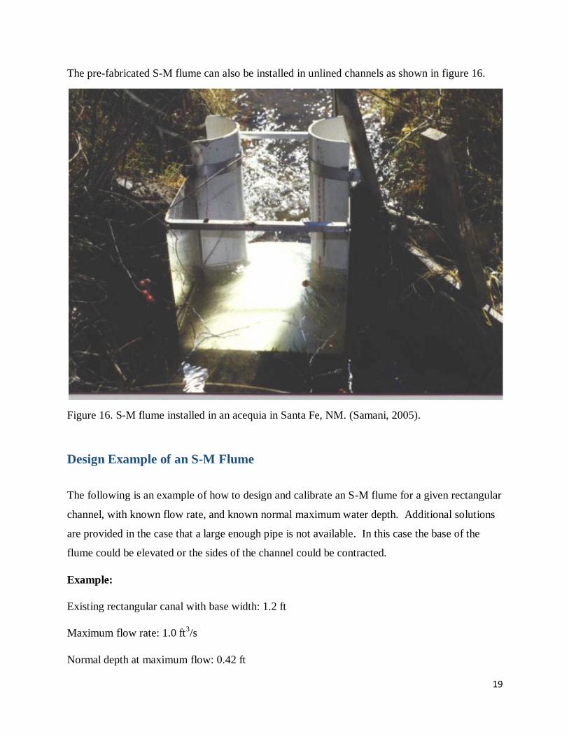
The pre-fabricated S-M flume can also be installed in unlined channels as shown in figure 16.
Figure 16. S-M flume installed in an acequia in Santa Fe, NM. (Samani, 2005).
Design Example of an S-M Flume
The following is an example of how to design and calibrate an S-M flume for a given rectangular
channel, with known flow rate, and known normal maximum water depth. Additional solutions
are provided in the case that a large enough pipe is not available. In this case the base of the
flume could be elevated or the sides of the channel could be contracted.
Example:
Existing rectangular canal with base width: 1.2 ft
Maximum flow rate: 1.0 ft3/s
Normal depth at maximum flow: 0.42 ft

20
We first assume a diameter of the interior vertical flume, generally in pipe sizes that are readily
available. For S-M flumes we also need to meet the minimum contraction ratio of 0.40. For this
example we will assume an outside diameter of 0.3 ft.
This gives a contraction ratio of 0.3/1.2 = 0.25, which is below the minimum contraction ratio
threshold.
Increasing d to 0.5 ft increases our contraction ration to 0.42 which meets the requirement.
B – d = 1.2 ft – 0.5 ft = 0.7 ft (equation 6)
Using equation 5:
H = 0.515 ft
Submergence ratio: 0.42/0.515 = .815, this still exceed the maximum submergence ratio of 0.8.
Therefore, we can increase the diameter of the pipe to d = 0.6 ft, D – d = 0.6 ft, and recalculate
H.
H = 0.562ft
Submergence ratio: 0.42/0.562 = 0.75 which meets the submergence requirement.
The entrance length would be a minimum of 0.562 feet, the exit length a minimum of 0.281 feet.
This flume would require a vertical pipe of outside diameter 0.6 ft or greater and would measure
flows up to 1.0 cfs (448.4 gpm).
Alternate Solutions
Another solution would be to elevate the base of the channel slightly instead of increasing the
pipe diameter from 0.3 ft to 0.6 ft.
Dividing the normal depth (0.42 ft) by the submergence limit (0.80), we obtain 0.42 ft/0.80 =
0.525 ft.

21
The upstream height must be at least 0.525 ft.
Using the first pipe of 0.3 ft, we obtained an upstream height of 0.515 ft.
Subtracting the upstream height (0.515 ft) from the required height (0.525 ft); 0.525 ft – 0.515 ft
= 0.010 ft.
By raising the base of the channel under the flume by 0.010 feet we would be able to use the
vertical pipe diameter of 0.3 ft and meet the required submergence ratio.
An additional solution would bet to further contract the sides of the channel to create a lower
submergence ratio (figure 13).
Supposing that we only have a pipe of diameter 0.3 feet, we could instead fill in each side of
channel with 0.3 feet of concrete or other material (figure 13).
This would create the same critical width (Bc) of 0.6 feet (1.2 ft – 0.6 ft), and give the same gage
height of 0.562 feet found in the first solution which has been verified to work.
Figure 17. S-M rectangular flume installed in an unlined ditch in southern New Mexico.

22
Trapezoidal Flumes (Samani and Magallanez, 1993)
Most existing irrigation canals are trapezoidal in shape due to the high amount of water that can
be conveyed through this shape and the natural shape the canals take due to erosion. As such, it
becomes increasingly relevant and convenient to design a low-cost, easily installed flume that
can be used to measure flow in trapezoidal canals. The flume was designed and installed
similarly to how circular flumes are installed, with a vertical pipe in the middle of a channel as
seen in figures 18 and 19.
Figure 18. Trapezoidal flume in southern New Mexico Irrigation canal located at GPS
coordinates: 32.391389, 106.846111.

23
Figure 19. Close up (upstream side) of previous flume, with visible rust patterns indicating
maximum water height and critical flow profile.
Inserting the coefficients from table 1 into equation 2, the equation for flow for this trapezoidal
flume is:
(7)
Where:
Q = discharge, ft3/s or m
3/s
H = height of water, ft or m
g = gravity, ft/s2 or m/s
2
Bc = width of channel at critical cross section in feet or meters. Given by:
(8)
24
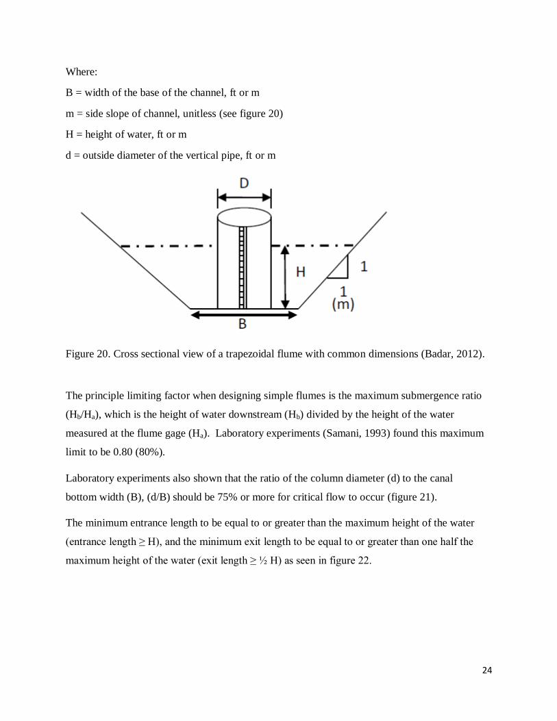
Where:
B = width of the base of the channel, ft or m
m = side slope of channel, unitless (see figure 20)
H = height of water, ft or m
d = outside diameter of the vertical pipe, ft or m
Figure 20. Cross sectional view of a trapezoidal flume with common dimensions (Badar, 2012).
The principle limiting factor when designing simple flumes is the maximum submergence ratio
(Hb/Ha), which is the height of water downstream (Hb) divided by the height of the water
measured at the flume gage (Ha). Laboratory experiments (Samani, 1993) found this maximum
limit to be 0.80 (80%).
Laboratory experiments also shown that the ratio of the column diameter (d) to the canal
bottom width (B), (d/B) should be 75% or more for critical flow to occur (figure 21).
The minimum entrance length to be equal to or greater than the maximum height of the water
(entrance length ≥ H), and the minimum exit length to be equal to or greater than one half the
maximum height of the water (exit length ≥ ½ H) as seen in figure 22.

25
Figure 21. Plan view of a trapezoidal flume indicating D, diameter of flume and B, canal bottom
width with design parameter D/B ≥ 0.75 (Badar, 2012).
Figure 22. Diagram indicating critical design parameters, where Hb/Ha ≤ 0.8.
H 1/2H
Ha
d
Hb
Q

26
Figure 23. Trapezoidal flume testing in the lab with critical flow.
Figure 24. Trapezoidal flume as seen from downstream with both visible flow depths.

27
Design Example of a Trapezoidal Flume
The following is an example of how to design and calibrate a trapezoidal flume for a given
channel, with known flow rate, and known normal maximum water depth. An additional
solution is provided in the case that a large enough pipe is not available. In this case the base of
the flume could be elevated.
Example:
Existing trapezoidal canal with base: 1.2 ft
Exisiting side slope: 1:1 (m:1)
Maximum flow rate: 1.0 ft3/s
Normal depth at maximum flow: 0.52 ft
We first assume a diameter of the vertical column, generally in readily available pipe sizes. We
also need to meet the requirement of the column width being a minimum of 75% of the base of
the channel. For this example we will assume an outside diameter of 0.9 ft.
B + 2*m*H - d = 1.2 ft + (2 * 1 * H) – 0.9 ft = 2H + 0.3 ft (equation 8)
Using equation 7:
H = 0.632 ft
Submergence ratio: 0.52/0.632 = 0.823, which exceeds the maximum submergence ratio of 0.8.
Therefore, we can increase the diameter of the column to d = 1.00 ft, D – d + 2mH = 0.20 +2H
ft, and recalculate H.
H = 0.650 ft
Submergence ratio: 0.52/0.650 = 0.80, which meets the submergence requirement.
The entrance length would be a minimum of 0.650 feet and the exit length would be a minimum
of 0.325 feet. This flume would require a vertical pipe of outside diameter 1.0 ft or greater and
would measure flows up to 1.0 cfs (448.4 gpm).

28
Alternate solution
Another solution would be to elevate the base of the channel slightly instead of increasing the
pipe diameter from 0.9 ft to 1.0 ft.
Dividing the normal depth (0.52 ft) by the submergence limit (0.80), we obtain 0.52 ft/0.80 =
0.65 ft.
Meaning the upstream height must be at least 0.65 ft.
Using the first pipe of 0.9 ft, we obtained an upstream height of 0.632 ft.
Subtracting the upstream height (0.632 ft) from the required height (0.65 ft); 0.65 ft – 0.632 ft =
0.018ft.
By raising the base of the channel under the flume by 0.018 feet we would be able to use the
vertical pipe diameter of 0.9 ft and meet the required submergence ratio.
Figure 25. Trapezoidal flume in use in Dushanbeh, Tajikistan.

29
General Recommendations
When designing a flume:
o The length of the flume should be ≥ 1.5 times the maximum height of the flow.
o The vertical column should be placed a minimum distance equal to the height of
the water level from the entrance and ½ the height of the water level from the exit
(Samani, 2005).
In all instances, the height of the water should be measured at the center of the upstream
side of the vertical column.
Often times, due to turbulence, the water level will be difficult to read, in such cases the
water level should be taken as an average of the fluctuating height.
A more desirable option to prevent the error caused by fluctuating water levels at the
column would be to use the column as stilling well by drilling a hole in the base of the
vertical column on the upstream side and measure the depth inside the. This will allow
water to enter the column with little turbulence on the inside. The column must be sealed
off preventing water from entering in other locations other than the most upstream side.
Rating tables can easily be constructed once a flume is in place to prevent the need for
continuous calculations.
o For example: In a known rectangular channel of base 1.2 feet, with an installed S-
M flume with half pipe diameters of 0.6 feet, equation 14 can be used to quickly
create a rating table as seen in table 2.

30
Table 2. Rating table created for a rectangular channel with from known flume dimensions.
Data loggers equipped with pressure transducers are often used for the continuous
recording of depth and calculation of instantaneous and cumulative flow.
As seen in the design examples, flumes can be elevated or contracted when the required
vertical pipe size is not available.
Due to the short length of simple flumes, they remain more accurate and reliable than
longer flumes when placed on a declining slope (Ontkean, 2015). However, flumes
should always be installed on level terrain to provide accurate flow measurements.
Maximum normal depth can be determined by looking at the high water mark in a
channel or by using Manning’s equation (Manning, 1981).

31
Chapter 2: Traditional Flow Measurement Devices
This Chapter discusses various traditional flow measurement devices including flumes, turnout
valves, and weirs. The type of structure used to measure flow is often determined by the
hydraulic conditions and the project objectives, with each type of structure having its benefits
and limitations.
Circular Gate (Turnout) Flow Measurement
Irrigation systems often have circular gates installed to help control and divert flow. As many of
Armco gates are already installed, the feasibility of using these gates as flow measuring devices
was investigated (Cadena and Magallanez, 2005). The gates investigated in this report are
Armco brand gates and this study is only relevant for them. It was found that flow could indeed
be measured using a modified orifice flow equation given by:
(9)
Where:
Q = discharge, ft3/s or m
3/s
y = vertical displacement of the gate (opening), ft or m
H = headloss through the opening, ft or m
g = acceleration of gravity, ft/s2 or m/s
2
D = diameter of the gate, ft or m
CD(y, D) = a function of diameter and gate opening given by:
(10)
Where b and m are constants calculated by the following formulas:

32
Imperial Metric
(11)
And
(12)
Where D is the diameter (feet or meters) of the gate in all cases.
Figure 26. Example of an Armco circular gate turnout (Cadena, 2005).
As seen in figure 26 the head loss can be measured in a stilling well installed one foot beyond the
opening of the gate. The diameter of the gate would remain constant, allowing the discharge
through the gate to be measured by knowing how much of the gate was opened (y), and
measuring the height of water in the stilling well.

33
Example Calculation of Flow through an Armco Circular Gate
The following is an example of how to calculate flow through an existing Armco circular gate
with given diameter (D), headloss (H), and opening (y).
Example:
D = 2 feet
y = 0.5 feet
H = 1 foot
Using equations 11 and 12 for imperial units we find that b = 0.8605 and m = -0.2950.
Substituting b and m into equation 10 yields: Cd = 0.7867.
Substituting Cd into equation 9 yields: 6.313 cfs.
Therefore, a circular gate of 2 foot diameter opened half a foot with a headloss of 1 foot has
6.313 cfs of discharge passing through it.
Traditional Flumes
Traditional flumes are excellent devices for monitoring the flow rate in open channels. They are
constructed of metal, concrete, wood, or fiberglass and can measure water over a wide variety of
flow ranges. Larger flumes are constructed on site, while smaller flumes can be prefabricated
and installed later on site.
Flumes require relatively little head loss when compared to weirs, are relatively insensitive to
approach velocity, and do not acquire as much sediment build up as found in weirs. Flumes
must be leveled and the flow entering the flume cannot contain waves or surges in order to
provide accurate flow measurements.
The construction of traditional flumes is a relatively expensive endeavor as considerable care
must be taken when forming them to the correct shape and dimensions including raising or
lowering the channel base. Professional installation is usually required to ensure that the
converging section, throat width, and diverging section are the correct size and dimensions.
While flumes can operate under submerged conditions, two measurements of water height are
34
required for accurate flow measurements under submerged conditions. Additionally, while
approach velocity is incorporated in the calibration of the flumes, traditional flumes are designed
to function parallel to the flow and will result in inaccurate measurement if located at right
angles to flowing streams, such as turnouts.
Parshall Flumes
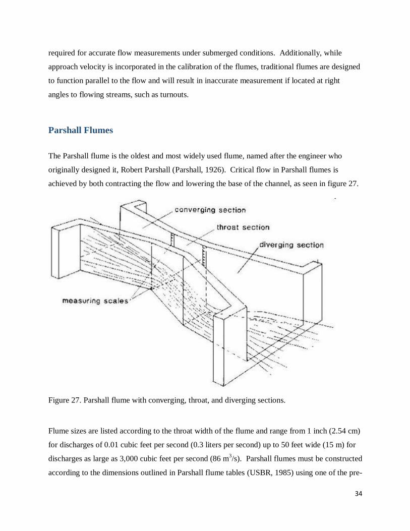
The Parshall flume is the oldest and most widely used flume, named after the engineer who
originally designed it, Robert Parshall (Parshall, 1926). Critical flow in Parshall flumes is
achieved by both contracting the flow and lowering the base of the channel, as seen in figure 27.
Figure 27. Parshall flume with converging, throat, and diverging sections.
Flume sizes are listed according to the throat width of the flume and range from 1 inch (2.54 cm)
for discharges of 0.01 cubic feet per second (0.3 liters per second) up to 50 feet wide (15 m) for
discharges as large as 3,000 cubic feet per second (86 m3/s). Parshall flumes must be constructed
according to the dimensions outlined in Parshall flume tables (USBR, 1985) using one of the pre-

35
set sizes. The typical dimensions for a Parshall flume are shown in figure 28. Parshall flumes
can operate in both unsubmerged (free-flow) and submerged conditions. However, additional
measurements (upstream and downstream depth) are needed. In addition the calibration
coefficients need to be recalculated when operating in submerged conditions.
Figure 28. Plan and profile views of a Parshall flume.
HHbb
HHaa

36
The free-flow equation for discharge through smaller Parshall flumes (from 1 inch to 8 feet) is
given by:
(13)
Where:
Q = flowrate, cfs
Ha = head, ft
n = constant dependent on throat width (table 3)
C = constant dependent on throat width (table 3)
Flumes with a throat width of 8 feet or more have their discharge calculated by:
(14)
Where:
Q = flowrate, cfs
Ha = head, ft
b = throat width, ft
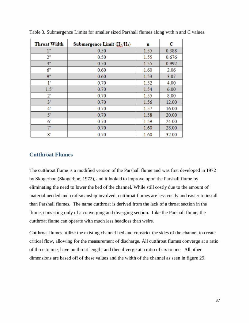
The degree of submergence is calculated by the ratio of the height of the water upstream of the
throat to that of the height of the water downstream of the throat (Ha/Hb). Parshall flumes have
different submergence ratios depending on the size of the flume as seen in table 3. If
submergence is less than or equal to the values given on the table, the discharge is considered
free-flow and can be calculated through direct application of these formulas. If the submergence
is greater than the limit for specific throat widths, further calculations are required to determine
the actual discharge. Guidelines and submergence curves for calculating flow can be found in
The Water Measurement Manual (USBR, 1984).
37
Table 3. Submergence Limits for smaller sized Parshall flumes along with n and C values.
Cutthroat Flumes
The cutthroat flume is a modified version of the Parshall flume and was first developed in 1972
by Skogerboe (Skogerboe, 1972), and it looked to improve upon the Parshall flume by
eliminating the need to lower the bed of the channel. While still costly due to the amount of
material needed and craftsmanship involved, cutthroat flumes are less costly and easier to install
than Parshall flumes. The name cutthroat is derived from the lack of a throat section in the
flume, consisting only of a converging and diverging section. Like the Parshall flume, the
cutthroat flume can operate with much less headloss than weirs.
Cutthroat flumes utilize the existing channel bed and constrict the sides of the channel to create
critical flow, allowing for the measurement of discharge. All cutthroat flumes converge at a ratio
of three to one, have no throat length, and then diverge at a ratio of six to one. All other
dimensions are based off of these values and the width of the channel as seen in figure 29.
38
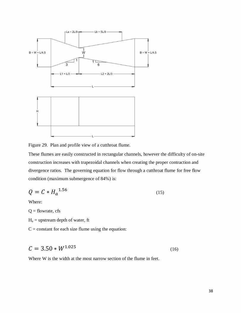
Figure 29. Plan and profile view of a cutthroat flume.
These flumes are easily constructed in rectangular channels, however the difficulty of on-site
construction increases with trapezoidal channels when creating the proper contraction and
divergence ratios. The governing equation for flow through a cutthroat flume for free flow
condition (maximum submergence of 84%) is:
(15)
Where:
Q = flowrate, cfs
Ha = upstream depth of water, ft
C = constant for each size flume using the equation:
(16)
Where W is the width at the most narrow section of the flume in feet.

39
Figure 30. Installed cutthroat flume.
Like the Parshall flume, the cutthroat flume can operate under submerged conditions, reaching
submergence limits up to 84 percent (downstream head divided by upsteam head). As the
submergence ratio passes this value, accurate discharge values can still be calculated by
measuring downstream depth and referencing submerged flow calibration curves found in
Design and Calibration of Submerged Open Channel Flow Measurement Structures: Part 3 –
Cutthroat Flumes (Skogerboe, 1967).
RBC Flumes
Replogle, Boss, Clemmens (RBC) flumes are a more recently implemented flume that utilizes a
trapezoidal cross section instead of the rectangular cross section needed for Parshall flumes
helping to reduce the cost of installation. Flow is contracted and forced into critical conditions
by raising the elevation of the base of the channel allowing the discharge to be measured. An
advantage of the RBC flume is that the flat floor used in RBC flumes allows it to be more easily
retrofitted into existing channels. RBC flumes are calibrated by computer analysis (through the
use of the free WinFlume computer program). Allowing for custom flume designs and rating
tables to be easily created for non-standard dimensions.

40
One of the disadvantages the RBC flume has over the Parshall flume is that the base of the
channel needs to be elevated which can allow sediment and debris to accumulate in low gradient
conditions affecting the accuracy of discharge measurements.
The RBC flume is essentially a small broad-crested weir (Sturm, 2012), similar to previously
mentioned weirs but with more flow-surface contact and discharge can then be calculated
accordingly. The equation for the discharge of a rectangular broad crested weir when water
passes through critical flow is:
(17)
Where:
Q = Flowrate, cfs
L = Weir length (channel width), ft
H = Height of upstream water above weir, ft
As shown in the diagram below.
Figure 31. Profile view of a basic RBC flume or broad crested weir, critical flow is created by
raising the bottom of the channel.
Generally, these flumes will have a ramp leading up to the throated section as shown in figure 32
to allow for an easier transition of water over the throat section.

41
Figure 32. An RBC flume ready to be installed.
These flumes are also often crafted on site by pouring concrete in an existing lined channel and
forming it to the desired specifications as shown in figure 33.
Figure 33. Casting an RBC flume in an existing canal.
It is recommended when constructing or using RBC flumes to use the program WinFlume
(http://www.usbr.gov/pmts/hydraulics_lab/winflume/) which creates rating tables and allows
discharge to be calculated directly (Wahl, 2012).

42
Weirs
Weirs are one of the oldest, simplest, and most reliable structures that can be used to measure the
flow of water in canals and ditches. Defined as a low dam built across a river or channel over
which water can flow, weirs regulate the flow of water downstream, thus allowing it to be
measured when properly constructed, installed, and maintained. Due to the simplicity of weirs,
the most critical elements can easily be inspected allowing improper installations to be easily
identified and quickly corrected. Weirs are accurate measuring devices once properly
constructed and installed, as only one depth of water can exist in the upstream pool for a given
discharge. Flowrates are determined by measuring the vertical distance from the crest of the
weir to the upstream height of water at a distance upstream of the weir. For this height to
properly determine the flow of water in a canal, the weir must have a regular shape, definite
dimensions, and have a pool of adequate size allowing the system to perform in a standard
manner.
Weirs require at least a 0.5 foot drop between the upstream and downstream water surfaces, a
loss in head often not available in ditches with flat grades. Water must also approach the weir
slowly, achieved by backing the water up in a weir pond created from the installation of the weir
itself. Due to this reduction in water velocity, if the water is carrying sediment, it will settle out
and fill the weir pond. As the pond fills, the velocity of the approaching water would increase,
resulting in inaccurate flow measurement at the weir. Grass and weeds tend to thrive in slow
water, leading to required maintenance of the weir pond to keep it free of sediment and weeds.
Weirs are generally divided into separate categories depending on the shape of the opening
through which the water passes. These weir classifications are: rectangular, Cipolletti, and v-
notch as shown in figures 36, 39, and 41 respectively. Rectangular weirs can be further divided
into two classes. Weirs placed in a rectangular channel where the side walls act as the ends of
the weir crest and do not contract are said to be suppressed rectangular weirs (figure 37), while
weirs that do not have a crest that extends all the way to the sidewall are said to be contracted
rectangular weirs (figure 34).

43
Contracted Rectangular Weirs
Contracted rectangular weirs is the more common type of rectangular weir and has the end of its
crest and sidewalls so far removed so as to allow for full contraction of flow to develop. This
contraction of flow is approximately the maximum contraction the flow would experience if
there were no sidewalls at all. The flow through a contracted rectangular weir is given by:
(18)
Where:
Q = flowrate, ft3/s
L = crest length, ft
H = head, ft
As shown in figures 34 and 35.
Figure 34. Cross section of contracted rectangular weir

44
Figure 35. Profile view of a sharp crested weir.
The head of water is the height of water above the crest of the weir which can be measured with
a ruler and the length of the weir would be a constant dimension making flowrate relatively easy
to determine with one measurement. To be effective in measuring the flow of water, rectangular
contracted weirs should be installed according to the following guidelines set forth by the United
States Bureau of Reclamation (USBR). These guidelines are as follows:
1. The upstream face of the bulkhead should be smooth and in a vertical plane perpendicular
to the axis of the channel.
2. The upstream face of the weir plate should be smooth, straight, and flush with the
upstream face of the bulkhead.
3. The entire crest should be a level, plane surface which forms a sharp, right-angled edge
where it intersects the upstream face. The thickness of the crest, measured in the
direction of flow, should be between 0.03 and 0.08 inch (about 1 to 2 mm). Both side
edges of rectangular weirs should be truly vertical and of the same thickness as the crest.
4. The upstream corners of the notch must be sharp. They should be machined of filed
perpendicular to the upstream face, free of burrs or scratches, and not smoothed off with
abrasive cloth or paper. Knife edges should be avoided because they are difficult to
maintain.
2H

45
5. The downstream edges of the notch should be relieved by chamfering if the plate is
thicker than the prescribed crest width. This chamfer should be at an angle of 45o or
more to the surface of the crest
6. The distance of the crest from the bottom of the approach channel (weir pool) should
preferably be not less than twice the depth of water above the crest and in no case less
than 1 foot.
7. The distance from the sides of the weir to the sides of the approach channel should
preferably be no less than twice the depth of water above the crest and never less than 1
foot.
8. The overflow sheet (nappe) should touch only the upstream edges of the crest and sides.
9. Maximum downstream pool level should be 0.2 foot (6 cm) below the crest elevation.
10. The measurement of head on the weir should be taken as the difference in elevation
between the crest and the water surface at a point upstream from the weir a distance four
times the maximum head on the crest.
11. The cross-sectional area of the approach channel should be at least 8 times that of the
overflow sheet at the crest for a distance upstream from 15 to 20 times the depth of the
sheet.
12. If the weir pool is smaller than defined by the above criteria, the velocity of approach
may be too high and the staff gage reading too low.
46
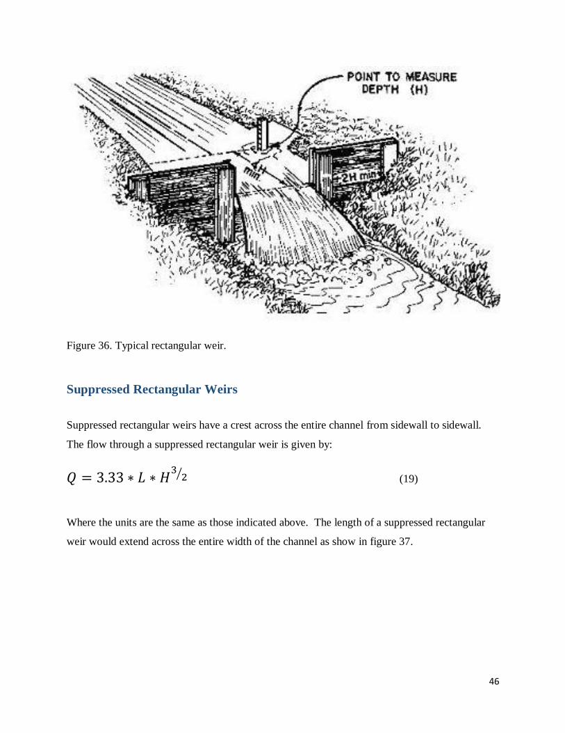
Figure 36. Typical rectangular weir.
Suppressed Rectangular Weirs
Suppressed rectangular weirs have a crest across the entire channel from sidewall to sidewall.
The flow through a suppressed rectangular weir is given by:
(19)
Where the units are the same as those indicated above. The length of a suppressed rectangular
weir would extend across the entire width of the channel as show in figure 37.
47
Figure 37. Cross sectional view of a suppressed rectangular weir.
Conditions for accuracy of measurement for this type of weir as exactly the same as those listed
above for contracted weirs with the exception that the sidewalls should coincide with the edge of
the crest and should extend beyond the crest to prevent lateral expansion of the nappe (water
flowing over the weir).
Cipolletti Weirs
Trapezoidal weirs are often called Cipolletti weirs after the engineer who developed them as a
way of eliminating the correction of the crest length needed for contracted rectangular weirs.
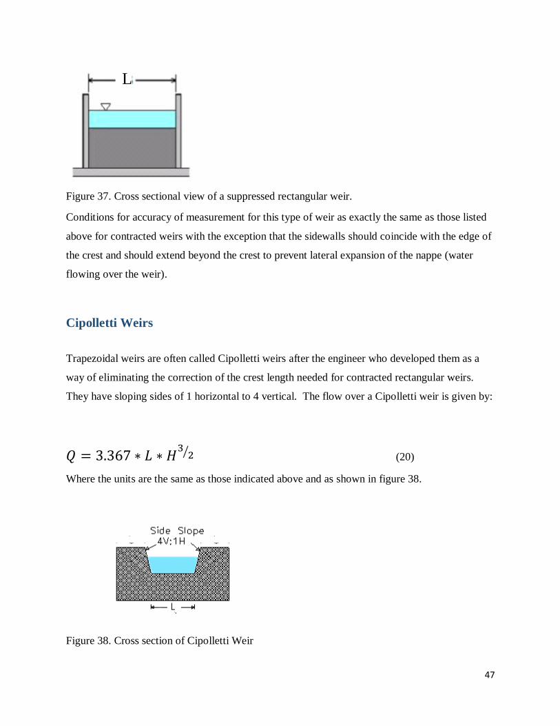
They have sloping sides of 1 horizontal to 4 vertical. The flow over a Cipolletti weir is given by:
(20)
Where the units are the same as those indicated above and as shown in figure 38.
Figure 38. Cross section of Cipolletti Weir
L

48
Conditions for accuracy of measurement for this type of weir are the same as those for a
contracted rectangular weir with the following additions. The weir should not be used for head
less than about 0.2 foot, nor for heads greater than one-third the crest length.
Figure 39. Typical Cipolletti weir.
V-notch Weirs
V-notch weir are triangular weirs with the generally accepted standard being the 90o notch and is
particularly adept at measuring small flows and can be used for flows which vary greatly. The
flow over a v-notch weir is given by:

49
(21)
Where the units are the same as those indicated above.
Figure 40. Cross sectional view of v-notch weir.
As seen in figure 40, the angle can be any that one chooses, however this angle is typically set at
90o. V-notch weirs are contracted weirs and can be built using the same guidelines listed for
rectangular contracted weirs.
Figure 41. Typical v-notch weir.

50
Figure 42. V-notch weir.
The v-notch and rectangular weir can also be combined to provide an accurate flow measurement
for both small and large flumes as demonstrated in figure 42. Once a certain discharge is
obtained, water will flow over the top of the flat crest as well as through the v-notch.
Figure 43. Combination V-notch and contracted rectangular weir.

51
References
Badar A.M., Ghare A. D. 2012. Development of Discharge Prediction Model for Trapezoidal
Canals using Simple Portable Flume. International Journal of Hydraulic Engineering.
1(5):37-42.
Cadena, F., Magallanez, H. 2005. Analytical Solution for Circular Gates as Flow Metering
Structures. J. Irrg. Drain. Engr. ASCE, 131(5), 451-456.
Hagar, W. H. 1988. Mobile Flume for Circular Channel. J. Irrg. Drain. Div. ASCE, 114(3), 520-
534.
Manning, R. 1891. On the flow of water in open channels and pipes. Transactions of the
Institution of Civil Engineers of Ireland 20: 161–20
Ontkean, G. R., Healy, L. H. 2015. Impact of non-level operation of a circular flume on
discharge measurements. The Canadian Society for Bioengineering. Paper No. CSBE15-
120.
Parshall, R. L. 1926 The Improved Venturi Flume. Trans., ASCE, 89, 841-880.
Samani, Z., Magallanez, H., Skaggs, R. 2005. A Simple Flow Measuring Device for Farms.
Water Task Force. Report 3.
Samani, Z., Magallanez, H. 1992. Hydraulic Characteristics of a Circular Flume. J. Irrg. Drain.
Engr. ASCE, 117(4), 559-567.
Samani, Z., Magallanez H. 1993. Measuring Water in Trapezoidal Canals. J. Irrg. Drain. Engr.
ASCE, 119(4), 181-186.
Samani, Z., Magallanez H. 2000. Simple Flume for Flow Measurement in Open Channel. J. Irrg.
Drain. Engr. ASCE, 126(2), 127-129.
Samani, Z., 2016. Three Simple Flumes for Open Channel. Paper in progress.
Stefano D. S., Piazza G. V. D., and Ferro, V. 2008. Field Testing of a Simple Flume (SMBF) for
Flow Measurement in Open Channels. J. Irrg. Drain. Engr. 134(2), 235-240.
Replogle, J.A. 1975. Critical Flow Flumes with Complex Cross Section. Proc. ASCE Irrg. Drain.
Div. Spec. Conf., ASCE, Aug. 13-15, 336-338.
Skogerboe, G.V., Bennet, R. S., and Walker, W. R. 1972. Generalized Discharge Relations for
Cutthroat Flumes. J. Irrg. Drain. Div., ASCE, 98(4), 569-583.
Skogerboe, G. V., Hyatt, M. L., Anderson, R. K., and Eggleston, K. O. 1967. Design and
Calibration of Submerged Open Channel Flow Measurement Structures: Part 3 –
Cutthroat Flumes. Report WG31-4. Utah Water Research Laboratory, College of
Engineering, Utah State University, Logan, UT.

52
Sturm, T. W., 2010. Open Channel Hydraulics, Second Edition. New York, NY.
United States Bureau of Reclamation (USBR). 1984. Water Measurement Manual. U.S. Dept. of
Interior, Denver, CO.
Wahl, L. T., A. J. Clemmes, M. G. Bos, J. A. Replogle. 2012. The WinFlume Home Page, US
Department of the Interior, USBR. http://www.usbr.gov/pmts/hydraulics_lab/winflume/