Embed Size (px)
Citation preview

Journal of University of Babylon for Engineering Sciences, Vol. (26), No. (9): 2018.
is licensed University of Babylon by Journal of University of Babylon for Engineering Sciences
.Creative Commons Attribution 4.0 International License under a
1
Simple, Low Cost, and Efficient Design of a PC-based DC Motor
Drive
Athraa Sabeeh Hasan
Electromechanical Engineering Department, University of Technology/ Baghdad
Submission date:- 3/5/2018 Acceptance date:15/8/2018 Publication date:-10/10/2018
Abstract:
In industrial applications, requiring variable speed and load characteristics, the DC motor is the
attractive piece of equipment; due to its ease of controllability. Pulse-width modulation (PWM) or
duty-cycle variation methods are commonly used in speed control of DC motors. A simple, low cost,
and efficient design for a control circuit uses the PWM to adjust the average voltage fed the DC motor
is proposed in this paper. The objective of this paper is to illustrate how the DC motor's speed could be
controlled using a 555 timer. This timer works like a changeable pulse width generator. The pulse
width can be changed via relays to add or remove resistors in the timer circuit. Using relays enable the
proposed circuit to drive higher-power motors. The designed circuit controls the speed of a Permanent
Magnet PM DC motor by means of the parallel port of a PC; therefore, the user will be able to control
the speed of the DC motor. C++ computer program is used to run the motor at four levels of speed. An
interface circuit is used to connect the motor to the parallel port. PC based control software is chosen to
get simplicity and ease of implementation.
Keywords: PWM, 555 timer, PC speed control, PMDC motor
1. Introduction:
Modern evolutions in science and technology result in a numerous applications of high
efficiency DC motor drives in multiple fields like electric trains, chemical process, rolling mills, home
electric appliances, and robotic manipulators, which need speed controllers to carry out tasks.
For a long time, the DC motors are widespread in the industry control field, because they have
numerous good characteristics, such as; high starting torque, easily linear controlled, and high response
performance, etc. The variant motor control method depends upon its variant performance. The
peripheral control apparatuses are adequate which contribute to more comprehensive achievement in
the industrial control system. Hence, the DC motor control is easier than other types of motors.
Nowadays, the control and measurement system could be implemented based on the computer [1].
Speed control represents the important advantage of DC motors. The motor speed has direct
proportion with the armature voltage and inverse proportion with the magnetic flux of the poles;
therefore, the rotor speed could be adjusted according to the field current and armature voltage. Speed
control can be achieved by variable battery tapping, variable supply voltage, resistors or electronic
controls [2].
In 21th century, the computers system have been applied in various application because it easy
to monitor. To access a system, the user only interface with the PC software without need explore
about hardware or manually control in computer system. It is not practical, in the contemporary
technology period, to use a manual controller because it may waste cost and time. So as to minimize
time and cost, it is necessary to suggest a controller based on PC, because it is portable. The users could
monitor their system at specific place without going to the plant (machine), specifically in industrial
application. As well as, the power could be minimized and preserved with computer which is more
reliable and precise. The computer assisted by developed software is able to interfacing with hardware
system, making the computer system reliable [2].
brought to you by COREView metadata, citation and similar papers at core.ac.uk
provided by Journals of University of Babylon

Journal of University of Babylon for Engineering Sciences, Vol. (26), No. (9): 2018.
2
One of the important advantages of using the PWM technique in speed control of DC motor is
that the signal stays digital always from the processor to the controlled system without need to digital-
to-analog conversion, which minimizes the noise effects. Therefore, the DC supply is chopped into
either fully ON or fully OFF. The voltage/current supply is fed into analog load through a repeating
series of the ON/OFF pulses. By giving sufficient bandwidth, any analog value can be encoded with
PWM. Another advantage of the PWM is that the pulses can extend into the full supply voltage and
yield higher motor torque, and capable to surmount the internal motor resistance more easily [2].
The PWM is an efficient way of digitally encoding the levels of analog signals. PC based
electrical appliances control is an interesting PC based research, mainly useful for industrial
applications, home automation, and supervisory control applications. PC based PWM speed controller
has become an essential in many implementations, starting with routines such as gate openers, window
shutters through PC fire alarms and metering to automotive implementations such remote keyless entry
and tire pressure monitoring systems [1].
There is enough number of research works in the literature talk about utilizing the solid-state
devices in the PC-based control of DC drives. Huang and Lee [1] designed a PID controller to change
the DC motor speed using the Lab VIEW software program, and demonstrated the motor speed in real-
time to get the response of the PID controller based system. Sánchez1 and Valenzuela [2] had been
proposed a control scheme in real-time without using a data acquisition board. So that the design was
based on using the PC parallel port and two microcontrollers to achieve data feedback, Meha et al. [3]
had investigated the speed control of DC motor using PWM technique. The desired speed of the motor
had been programmed with C# language through the communication with 8051 microcontroller with a
standard PC serial port. The microcontroller based closed-loop automatic DC motor speed control had
been introduced by Dewangan et al. [4]. A PMDC motor adjustable speed drive control was
implemented by Ravindran and Kumar [5] with software program in Visual Basic code and hardware
setup. The output of the proposed system is accomplished from the GUI of the LABVIEW. Gupta and
Deb [6] presented a cost effective method to control the speed of a low cost brushed DC motor used in
electric cars by integrating an IC 555 Timer with a high boost converter. This converter was used since
electric cars need high voltages and currents.
Yadav et al. [7] presented an open loop scheme for the speed control of a PMDC motor using an
AVR Microcontroller. The PC interfacing has been done using serial port (DB9 Connector). Kumari et
al. [8] had made an attempt to control the axes motion in CNC machine tools by controlling the speed
of both DC as well as Stepper motors. A PC-to-Motor interface and driver circuit board had been
designed and developed for the presented system. The software of the system had been developed using
LabVIEW-based graphical programming language. Chauhan and Semwal [9] implemented a PWM
based speed control of PMDC motor through RS232 serial communication port with PC. Controlling
the motor speed through tachogenerator as a speed feedback was executed using an ATmega8L
microcontroller. Shah and Deshmukh [10] implemented a PWM technique with the help of LM3524
for the speed control of PMDC motor fed by a DC chopper.
Petru and Mazen [11] presented an experimental setup for PWM controlling the speed of a DC
motor used to drive a conveyor belt. An H-bridge had been used to supply the DC motor that permits to
reverse the direction of the motor rotation. An ARDUINO UNO board, controlled by a program given
in the LabVIEW 2013 programming environment, and combined with an Atmega 328 microcontroller
was used to generate a the PWM signal.
The purpose of a digital DC motor control is to use a digital signal that describing the demanded
average voltage which needed to supply the DC motor. Operating and driving speed concept of a DC
motor need to be study. Therefore, this paper has to take a part to design and develop a computer-based
DC motor speed drive interface system. The paper has divided to two parts which are DC motor drive
circuit design and Personal Computer (PC) to parallel communication interface.
The current paper is developing to provide an efficient, simple, and low cost method for
controlling the speed of a DC motor via interfacing it with a PC through parallel port and using PWM
technique. The PWM signal can be generated by using an IC - NE555 timer. The pulse width can be
changed using relays by inserting or splitting resistors in the 555 circuit. These relays can good
interface enabling the proposed circuit to drive higher-power motors.

Journal of University of Babylon for Engineering Sciences, Vol. (26), No. (9): 2018.
3
2. Permanent Magnet DC Motor [12]:
The Permanent Magnet (PM) DC motor is one of the most widely used prime movers in
industry today. PMDC motors became increasingly widespread in applications require relatively low
torques and efficient use of space. The PMDC motors have construction differs from other DC motors,
in which; the magnetic field of the stator is generated by suitably located poles, made up of magnetic
materials. Differently, these motors do not require a field excitation, whether by means of the self-
excitation or separately techniques.
The equations that represent the PM motor operation are shown in equivalent 1 through 7.
The motor torque generated is relating to the armature current, Ia with a torque constant, kt
which can be defined by the motor geometry:
T = kt × Ia …………. (1)
Like the traditional DC motor, the rotation of the rotor generates a back emf, Eb, that is linearly
related to motor speed ωm by a voltage constant, ke:
Eb = ke ×ωm ………… (2)
The PM motor equivalent circuit is quite simple, since it does not require modeling the field
winding effects. The equivalent circuit and the torque-speed characteristic of a PM motor are shown
Fig. 1.
Fig. 1: Equivalent circuit and torque-speed characteristic of the PMDC motor
The circuit model shown in Fig. 1 can be used to extract the torque-speed characteristic, as
follows. For a fixed speed and thus fixed current, the inductor might be considered as a short-circuit
and get the following equation stated in (3) [12]:
mea
t
meaabaas
kRk
T
kRIERIV
……… (3)
Where Vs: motor input voltage source, Ra: motor armature winding resistance, T: motor torque,
Eb: motor back emf, Ke: voltage constant, and ωm: motor speed.
thus getting the speed - torque equations (4 to 7) [12]:
te
a
e
sm
kk
RT
k
V ……… (4)
te
a
mt
a
s kkR
kR
VT
……… (5)
t
a
s kR
VT 0 ……… (6)

Journal of University of Babylon for Engineering Sciences, Vol. (26), No. (9): 2018.
4
e
sm
k
V0 ……… (7)
Where To and ωmo are zero speed torque and speed at no load, respectively.
3. Pwm DC Motor Drive:
There are different types of DC motor drives used to drive different types of loads with different
values of speed. Therefore, many speed-controlling devices are greatly needed. The most common
speed control method is PWM technique. This technique depends on switching the power device ON
and OFF at a certain frequency, by changing the ON and OFF times "duty cycle".
Many applications employ a microcontroller to produce the required PWM signals. On the other
side, the 555 PWM circuit proposed here will produce an easy and low cost to build circuit, and
suitable understanding of the pulse width modulation idea. The main advantage of using 555 timer is
because that it does not require coding. It is very cheap, also useful in different applications where the
PWM setting needed only, sometimes be changed.
The PWM 555 timer circuit is formed as an astable oscillator. Once an input power is applied,
the 555 will be oscillated without using any external trigger.
3.1. The NE555 Timer [13], [14]:
NE555 can be introduced as a multipurpose integrated circuit IC that could execute both
multivibrator functions; monostable and astable. This circuit distinguishes with a greater accuracy,
repeatability, flexibility provided in the IC packages, and ease of application. The NE555 timer circuit
is able to produce precise pulses (time delays) or oscillation. In the time-delay "monostable" mode, the
pulse duration or time delay can be adjusted by using an external RC network. In the astable "clock
generator" mode, the output frequency may be changed by adding two external resistors R1, R2 and one
capacitor C. Fig. 2 shows typical circuits for the NE555 in both modes of operation, monostable and
astable operation. Also, it can be noted that the threshold and the trigger levels could be externally
controlled.
The pulse width, in the monostable circuit, can be computed as depicted in Eq. (10):
T = 1.1R1C … (10)
The positive pulse width, for the astable timer circuit could be determined as seen in Eq. (11)
and the negative pulse width could be defined as in Eq. (12):
t1 = 0.693(R1 + R2) C … (11)
t2 = 0.693R2C … (12)
Fig. 2: NE555 timer
In the proposed circuit, a stable mode is used so that the resistors R1 and R2 help in varying the
frequency of the output from the comparator of the timer. This helps in generating a pulse train used to
switch the transistor that used on. The biasing voltage used in the circuit is VCC. The output of the
comparator is a square wave with VCC amplitude as shown in Fig. 3:

Journal of University of Babylon for Engineering Sciences, Vol. (26), No. (9): 2018.
5
Fig. 3: PWM output waveform of the 555 timer
3.2. Astable Operation [13], [14]:
The astable (or multivibrator) circuit does not require trigger for starting. Once timer is
powered, the output will start to oscillate between VCC volts and 0 volts as shown in Fig. 3.
The astable circuit could be oscillated very quickly (up to millions of cycles/sec) or slowly
(down to many minutes/cycle). The time when the output is High is called ON time, or charge time (or
mark), while the time of Low output is called OFF time, or discharge time. The connection of 555 as a
stable mode is seen in Fig. 4.
Fig. 4: Connections of 555 timer in astable mode
As the capacitor voltage extends (2VCC /3), the discharge transistor is enabled (pin 7), and this
point in the circuit will be grounded. Capacitor C now will discharge through R2 alone. Starting at
(2VCC /3), it discharges towards ground, but again is interrupted halfway there, at (VCC /3). So, the
discharge time will be t2=0.693R2*C.
The astable timer circuit performance could be represented by Eqs. (13-16):
T = t1+t2=0.693(R1+2R2)C ……… (13)
CRRf
)2(
443.1
21 ……… (14)
21
211
2RR
RR
T
tCycleDuty
……… (15)
CCav VT
tV 1 ……… (16)
Where T is the total period of the pulse train, f is output circuit frequency, and Vav is the average
output voltage.
1t 2t
T
Vcc

Journal of University of Babylon for Engineering Sciences, Vol. (26), No. (9): 2018.
6
3.3. PC Parallel Port as Analog I/O Interface:
A parallel port (or printer port) is an interface type placed on computers used to connect various
peripherals. The parallel port data pins are Transistor-Transistor-Logic (TTL) outputs and generate a
typical logic high of (3-5V) DC and a logic low of 0V [15].
PC interfacing is the art of connecting computers and peripheral devices. The controller
designed in this paper utilizes the PC parallel port as an analog I/O interface. Only four bits are used as
analog interfaces through a PWM technique. This technique permits to build an analog interface
without using A/D or D/A converters. The analog voltages and currents could be used to control
processes directly. The analog control may seem as an intuitive and simple, it is not always practical or
economically attractive. Analog circuits tend to be drifted over time and difficult to tune. When the
analog circuits are digitally controlled, system power consumption and costs could be drastically
minimized. The PWM is an efficient technique for controlling analog circuits via digital signals. The
PWM is a method to digitally encode the analog signal levels. The duty cycle of a square wave shown
in Fig. 3 is modulated for encoding a specific analog signal level.
3.4. Generation of PWM Waveform Using IC 555 Timer:
In controlling DC motors, it is possible to utilize transistor, resistor, autotransformer, etc. to
execute linear current control, but this method has very large power consumptions. Nowadays, the
PWM controlling devices are the most often used. The PWM circuit operates by producing a square
wave with a changeable ON/OFF ratio. The average ON time might be changed from (0-100 %).
Consequently, an adjustable amount of electric power can be fed to the load. The PWM circuit is more
efficient than a resistive power controller [13].
The PWM and the driving motor circuit are respectively related to each other. The PWM is
generated by using IC 555 timer so as to control the DC motor speed. The principle is based on using
of square wave (duty cycle) for variation value of waveform. This is for generating the motor drive
signal. The torque loaded on the motor is determined by PWM duty cycle. The speed of the DC motor
is depending on duty cycle of PWM signal. PWM is also space saving, economical, and noise immune.
The PWM control can implemented by switching the power applied to the motor ON and OFF
very rapidly. The DC voltage is transferred to a square-wave signal. By changing, the duty cycle of the
signal (modulating the pulse width), the average input power and thus the motor speed could be
controlled.
Generating PWM on parallel (LPT1) port data pins (D0-D3), using C++ is very simple. For ON
period, high logic (1 means 3.49V) has to be applied on that data pin and low logic (0 means 0.09V) for
OFF period of pulse.
4. Design and Implementation
The proposed design can be divided into two parts; the first one is the design of Astable mode
by using 555 device with modeling of its duty cycle, while the second one is the design of driving
circuit for PMDC motor.
4.1. Design of Astable Mode (Oscillator)
4.1.1. (50-100) % Duty Cycle:
From Eqs. (11-16):
ON time; t1 = 0.693(R1+R2) C
OFF time; t2 = 0.693R2C
Total period; T = 0.693(R1+2R2) C
Duty cycle; t1/T = (R1+R2)/ (R1+2R2)
Other helpful values to be calculated are:
Mark/Space Ratio = 1+R1/R2.

Journal of University of Babylon for Engineering Sciences, Vol. (26), No. (9): 2018.
7
Frequency; f = 1/T = 1.443/ (R1+2R2) C; Hz (No of cycles per second)
If R2 >> R1 then ON time (t1) / OFF time (t2) ratio = 1 approx and the output is a square wave
with duty cycle of 50%.
If R2 << R1 then ON time (t1) / OFF time (t2) ratio = ∞ approx and the output is a constant DC
with duty cycle of 100%.
If R1=R2 then ON time (t1) / OFF time (t2) ratio = 2 and the output is a square wave with duty
cycle of 2/3 % = 66.67%.
Fig. 5: Free running frequency Fig. 6: Frequency vs. R1 for
vs. R1, R2 & C different values of C
Fig. 7: Duty cycle (average voltage) & frequency vs. R1 for different values of C of
astable mode (oscillator)
The duty cycle and corresponding output voltage of the time is shown in Fig. 7, they can be
calculated from Eqs. (15 and 16) and the value of the frequency. It can be seen that the duty cycle of
the 555 timer circuit in astable mode cannot reach less than 50%; Duty Cycle (50-100) %.
To extend the duty cycle to be from full off (0% duty cycle) to full on (100% duty cycle), some
modification may be done on the timer circuit as shown in Fig. 8. Diodes D1 and D2 will be added to
the circuit in Fig. 4 to be forward and backward paths for charging and discharging the capacitor C,
respectively.
4.1.2. Modified Duty Cycle (0-100) %
Selecting the ratios of R1 and R2 in Eq. 15 varies the duty cycle accordingly. If a duty cycle of
smaller than 50% is needed, even if R1=0, the charging time cannot be made smaller than the
discharging time since the charge path is: R1+R2, while the discharge path is: R2 alone. Hence, it is
necessary to insert a diode D1 in parallel with R2, cathode toward the timing capacitor. Another diode
D2 is not mandatory (in series with R2), cathode away from the timing capacitor. Thus, the charge path
will be R1, through the D1 into C, while the discharge is being through the D2 and R2 to the discharge
transistor. This schematic will give a duty cycle ranging from less than 5% to greater than 95%. It
should be noticed that for reliable practical operation, a minimum value of 3kΩ for R2 is needed to
confirm that oscillation starts.
10-5
100
105
1010
10-9
10-8
10-7
10-6
10-5
10-4
Frequency; f (Hz)
Ca
pa
cit
an
ce;
C (
F)
1M
Rt=10M
10K
1K
Rt = R1+2R2 for Astable timing
Rt = R1+R2 for Modified Astable
timing
100K
100
102
104
106
108
10-4
10-2
100
102
104
106
Resistance; R1 (Ohm)
Freq
uen
cy
; f
(Hz)
10 nF
0.1 uF
10 uF
1 nF
1 uF
100 uF
02
46
8
-5
0
550
60
70
80
90
100
Resistance; R1 (Ohm)Frequency; f (Hz)
Du
ty C
ycle
(%
)
1010
10
10
10
10100uF10
10uF
1uF
10
1 nF
0.1uF10nF
02
46
8
-5
0
52.5
3
3.5
4
4.5
5
Resistance; R1 (Ohm)Frequency; f (Hz)
Av
era
ge D
C V
olt
ag
e (
V)
1010
10 10
10
10
10
10nF0.1uF
1uF10uF
100uF 10
1nF

Journal of University of Babylon for Engineering Sciences, Vol. (26), No. (9): 2018.
8
Fig. 8: Modified duty cycle (astable); method of achieving duty cycles < 50%
When the capacitor C begins to charge through R1 and D1, the voltage on C rise to 2VCC/3, the
threshold (pin 6) will be activated, which makes the output (pin 3), and discharge (pin 7) are going
Low.
When the capacitor C starts to discharge through R2 and D2 and the voltage on C drops below of
VCC /3, the output (pin 3) and discharge (pin 7) pins are going High, and the cycle repeats.
Pin 5 is not used for an external voltage input; therefore, it is bypassed by a 0.01uF capacitor to
ground as shown previously in the Fig. 3.
Assuming R2 value to be fixed, the duty cycle varies only with respect to R1. Therefore,
Charging time; t1 = 0.683R1C (high output) … (17)
Discharging time; t2 = 0.693R2C (low output) … (18)
Total period; T = t1+t2= 0.683(R1+R2) C … (19)
Frequency; f = 1/T = 1.443 / (R1+R2) C … (20)
Duty cycle = t1 / T = 0.683R1C / 0.683(R1+R2) C = R1/ (R1+R2) … (21)
Mark/Space Ratio = t1 / t2=R1/R2 … (22)
All the desired values to be designed for the wanted duty cycle (or average output voltage) and
the oscillation frequency for the PWM output of the timer can be calculated according to the modified
equations (17-22) and using the curves shown in the Figs. (9and10). Therefore, the DC motor speed
could be controlled using a 555 timer over the full range by changing the signal mark-space ratio across
the full range, so it is possible to get any desired average output voltage ranging (0-5V).
Fig. 9: Frequency vs. R1 for different values of C for modified duty cycle
100
102
104
106
108
10-4
10-2
100
102
104
106
Resistance; R1 (Ohm)
Freq
uen
cy
; f
(Hz)
100uF
10uF
1uF
0.1uF
10nF
1 nF
7
C
6
1R
R2
1D
D2
ccV
3 Out

Journal of University of Babylon for Engineering Sciences, Vol. (26), No. (9): 2018.
9
Fig. 10: Duty cycle (average voltage) & frequency vs. R1 for different values of C for
modified duty cycle of astable mode (oscillator)
4.2. Drive Circuit Design
The PC employs a software program to control the motor speed. The motor is connected via an
interface circuit to the PC. The interface circuit shown in Fig. 11 includes IC1 (74LS244 buffer); IC2
(ULN2003 driver); IC3 (NE555 astable multivibrator circuit); relay switches S1, S2, S3 and S4; and T1
(2N2222) motor driver transistor. In the case of load currents up to about 600mA, a 2N2222A NPN
transistor is advised. For higher-power motors, the BJT transistor might be replaced by an IGBT or a
power MOSFET. The 555 timer works as a changeable pulse width generator. A Freewheeling diode,
D1 is used to prevent back-emf induced from inductive loads like brushed motors from destroying the
switching transistor. The pulse width can be changed by utilizing relays to insert or split resistors in the
555 timer circuit. IC3 has a square wave as an output voltage. This voltage is applied into the base of
transistor T1 through a current limiting resistor R3. The transistor T1 is utilized to drive the DC motor.
The computer program controls these resistors. In the first case, the switching relays; S1 and S2
are in ON case, and the charging resistor is R1C, where R1C≈0.1×R2=0.1*47k=4.7kΩ, is used to reduce
the on time of the pulse signal and, then, the motor speed to the lower limit.
When relays S1 and S3 are on, the IC3 555 generates a pulse signal with a duty cycle of 50%.
Therefore, the charging resistor, R1b, is equal to the discharging resistor, R2. In the third case, when the
relays S1 and S4 are on, and the charging resistor is R1a, where R1a ≈ 10×R2=10*47=470kΩ. This will
increase the on time of the pulse signal and, thus, the motor speed will be 90% of its maximum speed.
When, S1 is on while all other switches S2, S3 and S4 are off, the 555 timer output is adjusted
to logic one with a 100% duty cycle and thus driving the DC motor with its maximum speed. The
conditions of the ON/OFF operation of the relays and their corresponding motor speeds are
summarized in Table 1.
02
46
8
-5
0
50
20
40
60
80
100
Resistance; R1 (Ohm)Frequency; f (Hz)
Du
ty C
ycle
(%
)
10 1010
1010
1010
10
1 nF
10uF
100uF
1uF0.1uF
10nF
02
46
8
-5
0
50
1
2
3
4
5
Resistance; R1 (Ohm)Frequency; f (Hz)
Av
era
ge D
C V
olt
ag
e (
V)
1010
1010
1010
10 0.1uF
10uF100uF
10nF
1uF
1 nF
10

Journal of University of Babylon for Engineering Sciences, Vol. (26), No. (9): 2018.
10
Fig. 11: Speed control of a 5V PMDC motor via the PC's parallel port
Table 1: Switch States and Generated PC Sequences
D0 D1 D2 D3 S1 S2 S3 S4
Output
voltage
(V)
Duty
cycle
(%)
Speed
(rpm)
Motor speed
status
1 1 1 1 off off off off 0 0 0 Stop
1 1 0 0 on on off off 0.5 10 230 Minimum
1 0 1 0 on off on off 2.5 50 1520 Medium
0 1 1 0 on off off on 4 90 2700 High
1 1 1 0 on off off off 5 100 2990 Maximum
The code is prompting to choose a specific speed, stores the selection as an integer variable
choice, produces the right digital sequence, and stores it with another integer variable. By using the
outportb function, the value of the integer variable data at the PC's parallel port could be placed. The
program used the kbhit function for stopping the DC motor when hitting any key on the PC keyboard.
The software has been written in "C++" language and compiled using Turbo C++ compiler. Firstly, as
the motor is switched off, the program is prompting to press ''Enter" key to start the motor. Once the
key is pressed, the motor begins running at low speed. After a few seconds, the program will ask to
press any key on the keyboard to go to the next screen for controlling the motor speed. This screen has
options to increase and decrease the motor speed and also to exit from the program. To vary the motor
speed, enter the choices (1-4) and press ''Enter" key
This work varies the motor speed, one step at a time, and the message of "Speed decreased" or
"Speed increased" will be shown on the screen. To return to the main menu, certainly, again press
"Enter" key.
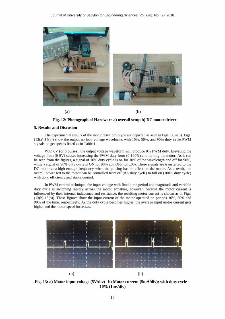
The circuit prototype has been built on a PC board to experimentally validate the designed
PWM speed control DC motor drive as demonstrated in Fig. 12.
Switch Relay
1
2
3
4
5
6
7
8
9
10
11
12
13
14
15
16
17
18
19
20
21
22
23
24
25
0D
1D
2D
3D
IC2
ULN2003
1
2
3
9
8
16
15
14
4 13
1IC
74LS244
2
4
6
20
10 19 1
14
16
18
8 12
Switch
Relay#3
Switch
Relay#1
Switch
Relay#4
Switch
Relay#2
IN4148
R1a 470K
IN4148
R1c 4.7K
IN4148 R2
47K
C 10nF
IN4148
R1b 47K
LPT 1
R3 1K T1
2N2222
1C
0.1 µF
+ 5V
1
IC3
NE555
7
4 8
3
2 5
6
GND
PMDC
Motor
+
-
D1
1N4001
Journal of University of Babylon for Engineering Sciences, Vol. (26), No. (9): 2018.
11
(a) (b)
Fig. 12: Photograph of Hardware a) overall setup b) DC motor driver
5. Results and Discusion
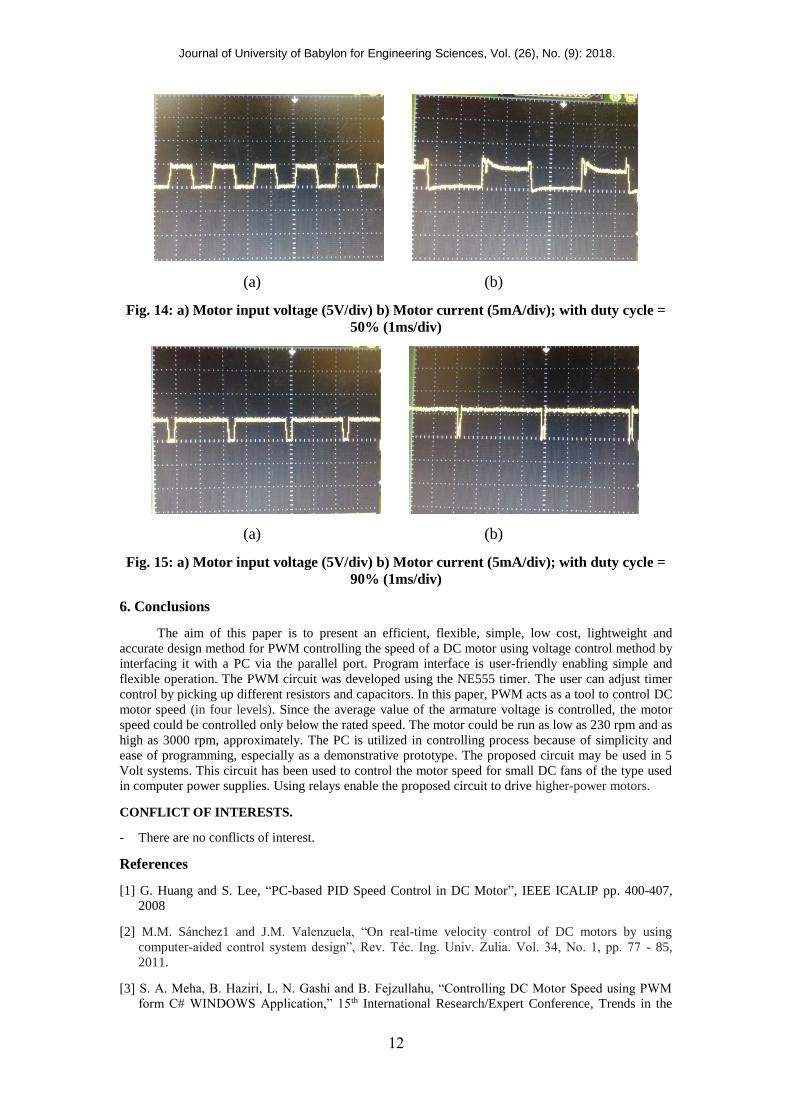
The experimental results of the motor drive prototype are depicted as seen in Figs. (13-15). Figs.
(13(a)-15(a)) show the output no load voltage waveforms with 10%, 50%, and 90% duty cycle PWM
signals, to get speeds listed as in Table 1.
With 0V (or 0 pulses), the output voltage waveform will produce 0% PWM duty. Elevating the
voltage from (0-5V) causes increasing the PWM duty from (0-100%) and turning the motor. As it can
be seen from the figures, a signal of 10% duty cycle is on for 10% of the wavelength and off for 90%,
while a signal of 90% duty cycle is ON for 90% and OFF for 10%. These signals are transferred to the
DC motor at a high enough frequency when the pulsing has no effect on the motor. As a result, the
overall power fed to the motor can be controlled from off (0% duty cycle) to full on (100% duty cycle)
with good efficiency and stable control.
In PWM control technique, the input voltage with fixed time period and magnitude and variable
duty cycle is switching rapidly across the motor armature, however, because the motor current is
influenced by their internal inductance and resistance, the resulting motor current is shown as in Figs.
(13(b)-15(b)). These figures show the input current of the motor operated on periods 10%, 50% and
90% of the time, respectively. As the duty cycle becomes higher, the average input motor current gets
higher and the motor speed increases.
(a) (b)
Fig. 13: a) Motor input voltage (5V/div) b) Motor current (5mA/div); with duty cycle =
10% (1ms/div)
Journal of University of Babylon for Engineering Sciences, Vol. (26), No. (9): 2018.
12
(a) (b)
Fig. 14: a) Motor input voltage (5V/div) b) Motor current (5mA/div); with duty cycle =
50% (1ms/div)
(a) (b)
Fig. 15: a) Motor input voltage (5V/div) b) Motor current (5mA/div); with duty cycle =
90% (1ms/div)
6. Conclusions
The aim of this paper is to present an efficient, flexible, simple, low cost, lightweight and
accurate design method for PWM controlling the speed of a DC motor using voltage control method by
interfacing it with a PC via the parallel port. Program interface is user-friendly enabling simple and
flexible operation. The PWM circuit was developed using the NE555 timer. The user can adjust timer
control by picking up different resistors and capacitors. In this paper, PWM acts as a tool to control DC
motor speed (in four levels). Since the average value of the armature voltage is controlled, the motor
speed could be controlled only below the rated speed. The motor could be run as low as 230 rpm and as
high as 3000 rpm, approximately. The PC is utilized in controlling process because of simplicity and
ease of programming, especially as a demonstrative prototype. The proposed circuit may be used in 5
Volt systems. This circuit has been used to control the motor speed for small DC fans of the type used
in computer power supplies. Using relays enable the proposed circuit to drive higher-power motors.
CONFLICT OF INTERESTS.
- There are no conflicts of interest.
References
[1] G. Huang and S. Lee, “PC-based PID Speed Control in DC Motor”, IEEE ICALIP pp. 400-407,
2008
[2] M.M. Sánchez1 and J.M. Valenzuela, “On real-time velocity control of DC motors by using
computer-aided control system design”, Rev. Téc. Ing. Univ. Zulia. Vol. 34, No. 1, pp. 77 - 85,
2011.
[3] S. A. Meha, B. Haziri, L. N. Gashi and B. Fejzullahu, “Controlling DC Motor Speed using PWM
form C# WINDOWS Application,” 15th International Research/Expert Conference, Trends in the

Journal of University of Babylon for Engineering Sciences, Vol. (26), No. (9): 2018.
13
Development of Machinery and Associated Technology” TMT 2011, Prague, Czech Republic, 12-
18 Sep. 2011.
[4] A.K. Dewangan, N. Chakraborty, S. Shukla, and V. Yadu, “PWM Based Automatic Closed Loop
Speed Control of DC Motor”, International Journal of Engineering Trends and Technology, Vol. 3
Issue2-, pp. 110-112, 2012.
[5] R. Ravindran and A. Kumar, “A DC Motor Speed Controller using LABVIEW and Visual Basic,
International Journal of Electronics & Communication Technology”, IJECT Vol. 3, Issue 1, Jan. -
pp. 144-146, March 2012.
[6] V. Gupta and A. Deb, “Speed Control of Brushed DC Motor for Low Cost Electric Cars”, Electric
Vehicle Conference (IEVC), 2012 IEEE International, 16 April 2012.
[7] A. Yadav, G. Kaur and A. Sharma, “Microcontroller Based Open-loop Speed Control System for
DC Motor”, International Journal of Research in Engineering & Applied Sciences, IJREAS Vol. 2,
Issue 6, pp. 14-22, June 2012.
[8] D.K.K. Kumari, A. Kumar, S. Narang, “Physical Implementation and Control of Multi- Axis
Motion Control System using LABVIEW”, International Conference on Innovations in Electrical
and Electronics Engineering (ICIEE'2012) Dubai (UAE), pp. 272-276, Oct. 6-7, 2012.
[9] J.S. Chauhan and S. Semwal, “Microcontroller Based Speed Control of DC Geared Motor through
RS-232 Interface with PC”, International Journal of Engineering Research and Applications, Vol. 3,
Issue1, pp. 778-783, Jan/Feb 2013.
[10] D.K. Shah, and B.T. Deshmukh, “Speed Control of PMDC Motor Using LM3524 PWM IC,”
International Journal of Computer Technology and Electronics Engineering, Vol. 3, Special Issue,
pp. 57-59, March-April 2013.
[11] L. Petru and G. Mazen, “PWM Control of a DC Motor Used to Drive a Conveyor Belt”, Procedia
Engineering, Vol. 100, pp. 299-304, 2015.
[12] G. Rizzoni, Principles and Applications of Electrical Engineering, McGraw Hill, 2004.
[13] L. Tian, Position and Timing Control with DC Motor Using 555 Timer, Application Note.
[14] NE555 and NE556 applications AN170, Philips Semiconductors Application Note, Dec. 1988.
[15] P.H. Anderson, Use of a PC Printer Port for Control and Data Acquisition.
http://www.access.digex.net/~pha. On March 22, 2018.

Journal of University of Babylon for Engineering Sciences, Vol. (26), No. (9): 2018.
14
555Relays
PMDC5V
C++
PMD .محرك الكمبيوتر،التحكم في سرعة جهاز الموقت، PWM: 555 الداله كلمات