Embed Size (px)
Citation preview

Standard Switch Orro Switch
This installation guide is to be used only if you are installing 1 Orro Switch where the
light(s) is controlled by 2 switches.
Simple Multiway Installation Guide

2
Need Help?We're ready to assist you.
Installation FAQ:
General support:
Urgent issues:
Support hours:
getorro.com/setupfaq
(747) 253 0608
Weekdays 7am-7pm (PST)Weekends 10am-6pm (PST)

1
Before We Start 3
Check Compatibility 7
Prepare for Install 11
Identify Wires 16
Install Orro 23
Set Up Orro
Troubleshooting
33
41

2
Before We Start
3
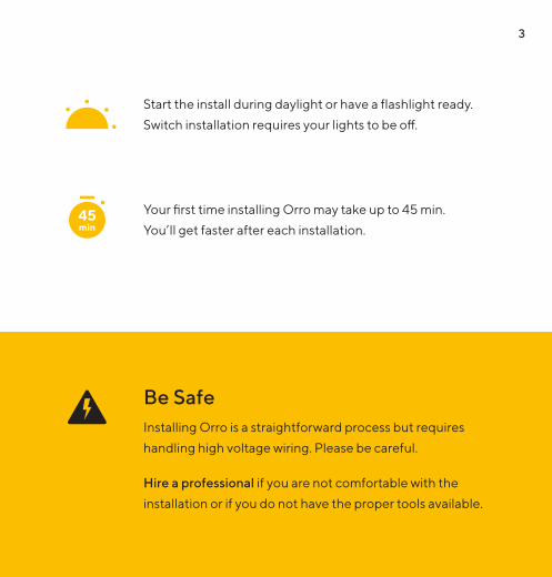
Installing Orro is a straightforward process but requires
handling high voltage wiring. Please be careful.
Hire a professional if you are not comfortable with the
installation or if you do not have the proper tools available.
Start the install during daylight or have a flashlight ready.
Switch installation requires your lights to be off.
Your first time installing Orro may take up to 45 min.
You’ll get faster after each installation.
Be Safe
45min

4
What’s in the Box
4x Wire Connectors 2x Mounting Screws2x Plate Screws
6x Wire Labels
1x Orro Switch1x Faceplate & Mount 4x Extension Wires

5
Tools Needed
Power tools are not recommended.
Phillips Screwdriver
Flathead Screwdriver
Pliers (recommended)

6
Check Compatibility

7
Maximum Load
Calculate the Total Load of your current light setup:
Identify your bulb type:
LED CFL Incandescent Halogen
Number of bulbs controlled by switch
Wattage of single bulbx[ [] ] = Total Load
LED MagLowVCFL Incandescent
*360W max load if switch is located in a wall box with more than one switch (multi-gang box)
ElecLowVHalogen Fluorescent
150WMax Load
Bulb Type
300W 500W* 5A
Total Load must be less than Max Load (based on bulb type):
Example: [ 4 LED bulbs ] x [ 10 watts ] = 40 watts total load
Common bulb types:
(often plastic) (often glass)
1
2
3

8
120V/60 Hz power is standard in residential homes in USA and Canada.
Orro does not rely on WiFi to make lighting decisions. However, the
switch must be connected to WiFi for setup, enabling certain features,
and getting updates.
120V/60 Hz Power Required
WiFi Required for Setup

9
Orro Switch must be installed in the location where the switch is connected to the bulb.
If you are unsure which switch is connected to the bulb, please choose
one switch to replace. If the incorrect switch is selected, you will just
need to try again and replace the other switch.
If you are unsure, hire an electrician
to complete installation.
Multiway Switch Diagram
Install Orro Switch here
TRAVELLER WIRES
BULBPOWER

10
Prepare for Install

11
Where is my circuit breaker?Breakers may be found in a garage, hallway, or basement. If you can’t
find the specific breaker, turn off the master breaker. If you are installing
your switch in a multi-switch gang box, turn off breakers for all switches.
Turn Off Power1
Turn off the circuit breaker for
the light switch you’re replacing.
Check the power is OFF by toggling your light switch on and off.
Your lights should NOT turn on.

12
Remove Faceplate2
• Unscrew or pop off the existing faceplate.
• If there is dried paint connecting the plate to the wall, use a box cutter to remove the faceplate cleanly.
Remove the screws from the top and bottom
of the switch.
Unscrew Switch3

13
Pull switch out as far as possible so that you can clearly
see all the wires in the switch box
Pull Switch Out of the Wall4
Do NOT detach any wires!*

14
Take a photo showing the existing wire connections
from the wall to the back of your switch. This will be
useful if you ever need to re-attach your old switch.
Take a Photo5

15
Identify Wires

16
Having trouble finding neutral wires? Call us: (747) 253 0608
Identify Neutral Wire(s)1
Neutral wire (white)
• A neutral wire is required for the Orro Switch to work.
• Neutral wires are often white and can be found as a single wire or bundle of wires..
• They may or may not be connected to your switch.

17
Label Neutral Wire(s)2
Use the included sticker to label neutral wire(s).
Label neutral wire(s) coming out of the wall.
Label the wire beyond the wire nuts

18
Label Ground Wire3
• Ground wires are often green or bare copper and can be found either as a single wire or bundle. Label these wires.
• This wire may or may not be connected to the switch. Label all ground wire(s) coming out of the wall.
Note: Your switch
wire terminal
positions may
not match this
illustration exactly
(Back of switch)
GROUND

19
Label Traveller Wires4
• Find and label the two wires attached to the same color screw terminals. Both terminals will often be a gold color screw.
• Wire colors are often black and/or red.
(Back of switch)
T2T1
GROUND

20
Label the remaining wire attached to your switch with a "Load" sticker. This wire carries power to your lights.
Label Load Wire5
GROUND
LO AD
T1 T2
(Back of switch)

21
Screwed-In Wires Built-In Wires
AND / OR
Remove Old Switch6
Possible Switch Configurations
If your wires are held in by screws, avoid removing the screws completely.*
Disconnect the wall wires from your switch. Depending on your switch type, either loosen the screws or remove the wire nuts. For wires inserted into ports, either remove the wires from the ports or cut the wires to remove them.

22
Install Orro
23
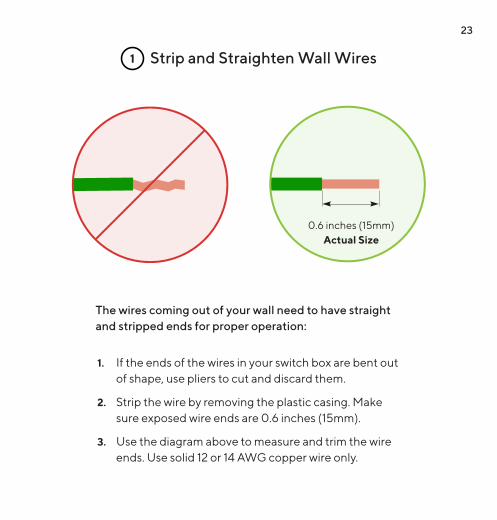
Strip and Straighten Wall Wires1
0.6 inches (15mm)Actual Size
1. If the ends of the wires in your switch box are bent out of shape, use pliers to cut and discard them.
2. Strip the wire by removing the plastic casing. Make sure exposed wire ends are 0.6 inches (15mm).
3. Use the diagram above to measure and trim the wire ends. Use solid 12 or 14 AWG copper wire only.
The wires coming out of your wall need to have straight and stripped ends for proper operation:
24
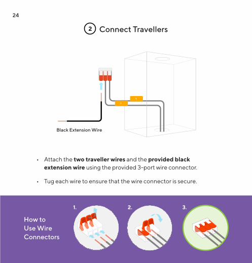
Connect Travellers2
• Attach the two traveller wires and the provided black extension wire using the provided 3-port wire connector.
• Tug each wire to ensure that the wire connector is secure.
Black Extension Wire
T
T
How to Use Wire Connectors
1. 3.2.

25
Connect Neutral Wires3
• Add the included white extension wire to the neutral wire bundle
• Make sure that all neutral wires have been connected together using a wire nut or the included wire connector.
White Extension Wire
How to Use Wire Nuts
1. Hold the ends of the wires parallel together.
2. Screw on the wire nut clockwise until secure.
3. Tug each wire to ensure that the wire nut is secure.

26
Connect Ground Wires4
Green Extension Wire
• If there is a bundle of ground wires, please add the included green extension wire to the bundle using the wire nut currently connecting the wire bundle together.
• Make sure that all ground wires have been connected together using a wire nut or the included wire connector.
If there is only a single exposed ground wire, skip this step.

27
Plug In Wires5
1. Plug the Load wire into the red port
2. Plug the Traveller extension wire goes into the black port
3. Plug the Neutral extension wire goes into the white port
4. Plug the Ground wire goes into the green port
NEUTRAL
To detach wires: slide the toggle to the left.
*

28
To detach wires, hold slider to the left.
Tug on the wires connected to the Switch and the wire connectors. Make sure that the wires are not loose.
Check Wire Connections6

29
Make room for the Orro switch by pushing each wire as far
as possible into the back of the switch box.
Push Wires Deep into Switch Box7
Please do NOT force the Switch into the wall.

30
Check Switch Fit8
Do not use tools to push wires in. They may damage the wires.
• With light pressure, push your Orro Switch into the switch box.
• The Switch should sit flush against the wall – if not, pull the Switch out and try rearranging the wires.
31
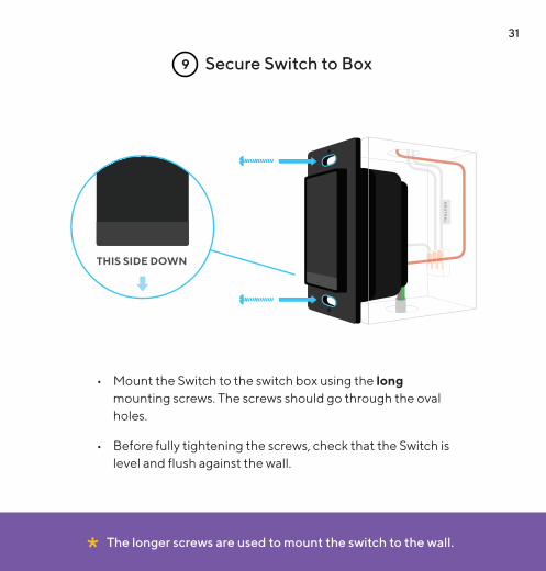
Secure Switch to Box9
The longer screws are used to mount the switch to the wall.*
• Mount the Switch to the switch box using the long mounting screws. The screws should go through the oval holes.
• Before fully tightening the screws, check that the Switch is level and flush against the wall.

32
Setup Orro

33
Go to your circuit breaker and turn the power back on.
Turn On Power1

34
Check Screen2
1. Give your Switch 30 seconds to power on. The lights may stay off during this process.
2. Check to see that the screen lights up.
3. If you Switch does not turn on, go to page 41 for troubleshooting.

35
Detach Mount from Faceplate3
Push a flathead screwdriver into the slot at the bottom of the faceplate until it separates from the mount. Pry apart the two pieces.

36
Attach Faceplate4
Use the short screws to attach the faceplate mount.
Push faceplate onto the mount and snap it into place.

37
Tap “START” on the Switch and follow the on-screen instructions to begin setup.
Follow Switch Instructions5

38
Sign up and complete setup in the app.
Complete Setup7Get the App6

39
Multiway functionality will not work properly until the Orro Switch has been updated to
the latest software version.
Update to Latest Software8
2x
Swipe from left to right to access the update screen.
If there is a system update available, tap the arrow to
start update.
SYSTEM UPDATE
START
18.42.4

40
Turn On Simple Multiway9
Make sure to turn Simple Multiway on.
Sensitivity
Simple Multiway
Tap the area that contains the version number, below the
arrow button.
SYSTEM UPDATE
START
18.42.4
Tap "Multiway".
Multiway
Bulb Settings
Device Info

41
Having trouble? Call us: (747) 253 0608
If your Switch does not turn on but you want to install Orro in this location, please go to www.getorro.com/3wayinstallation to look at further options.
If after installation, your Switch does not turn on:
If your Switch still does not turn on:
Turn on the circuit breaker and wait a minute to see if theSwitch powers on.
Re-install your old switch and revert to original setup
Make sure all wires are securely connected to correct Switch ports.
Remove your Orro Switch
Turn off the circuit breaker.
Turn off the circuit breaker.
1
1
2
2
3
3
Install Orro Switch in the alternate switch location and begin setup from pg. 10.
4
Troubleshooting
42
This device complies with Part 15 of the FCC Rules. Operation is subject to thefollowing two conditions:(1) this device may not cause harmful interference, and(2) this device must accept any interference received, including interference thatmay cause undesired operation.
This equipment has been tested and found to comply with the limits for a Class Bdigital device, pursuant to part 15 of the FCC Rules. These limits are designed to providereasonable protection against harmful interference in a residential installation. Thisequipment generates, uses and can radiate radio frequency energy and, if not installed andused in accordance with the instructions, may cause harmful interference to radiocommunications. However, there is no guarantee that interference will not occur in aparticular installation. If this equipment does cause harmful interference to radio ortelevision reception, which can be determined by turning the equipment off and on, the user isencouraged to try to correct the interference by one or more of the following measures: 1) Reorient or relocate the receiving antenna; 2) Increase the separation between the equipment and receiver; 3) Connect the equipment into an outlet on a circuit different from that to which the receiver is connected; 4) Consult the dealer or an experienced radio/TV technician for help.
WARNING: Any changes or modifications not expressively approved by Edison Labs, Inc. could void the user’s authority to operate this equipment.
This equipment complies with FCC radiation exposure limits set forth for an uncontrolled environment. This equipment should be installed and operated with a minimum distance of 20cm between the radiator and your body.
Warranty: One year limited warranty included. Visit www.getorro.com/legal for more details.