Embed Size (px)
Citation preview

TECHNICAL NOTES
Dow
nloa
ded
from
asc
elib
rary
.org
by
Uni
vers
ity o
f E
xete
r on
03/
21/1
3. C
opyr
ight
ASC
E. F
or p
erso
nal u
se o
nly;
all
righ
ts r
eser
ved.
Simple Single-Surface Failure Criterion for ConcreteSean D. Hinchberger1
Abstract: This technical note presents a new single-surface failure criterion for concrete that is derived using an approach developed forgeologic materials. The main advantage of the proposed failure criterion is its simplicity and ease of implementation into nonlinearfinite-element programs compared to existing criteria based on tension and compression meridians and a third function defining thedeviatoric trace between meridians. The new failure criterion is able to closely describe concrete strength under general three-dimensionalstress states and it gives improved predictions of concrete strength under plane stress conditions compared to existing single functionmodels. A method for deriving the strength parameters is presented so that practitioners may consider adapting the function for materialssuch as high-strength or steel fiber-reinforced concrete. The work summarized herein is considered novel practical information that shouldbe of use to practitioners wanting to implement simple phenomenological models for concrete in their finite element codes.
DOI: 10.1061/�ASCE�0733-9399�2009�135:7�729�
CE Database subject headings: Concrete; Material properties; Compressive strength; Tensile strength; Biaxial stress; Triaxial stress;Failures.
Introduction
Numerous phenomenological failure criteria have been proposedfor concrete subject to monotonic loading. Generally, such failurecriteria are defined using either multiple functions �Kupfer andGerstle 1973; Willam and Warnke 1975; Kotsovos 1979; Seowand Swaddiwudhipong 2005� or a single function derived in termsof the stress invariants I1= tr �, J2= �s :s� /2, and J3=det�s�, wheres=�− �I1 /3�� �Ottosen 1977; Lade 1982; Desai et al. 1986;Huang 1995; and Kang and Willam 1999�. Typically, the maindrawback of existing failure criteria is their complexity. In addi-tion, some single-surface failure criteria are unable to satisfacto-rily predict the strength of concrete under plane stress conditions�Desai et al. 1986; Kang and Willam 1999�.
This technical note describes the derivation of a single-surfacefailure criterion for concrete using an approach developed forgeologic materials �Desai et al. 1986�. The proposed criterionis derived in terms of the stress invariants I1, J2, and J3, and itis calibrated based on experimental measurements summarizedby Seow and Swaddiwudhipong �2005�. The primary advantageof the new failure criterion compared to existing criteria isits simplicity. In addition, it is shown that the new criterion isable to closely describe concrete strength under general three-dimensional stress states and it gives improved predictions ofconcrete strength compared to existing single function modelssuch as those by Ottosen �1977� and Kang and Willam �1999�. Inthe following sections, existing strength criteria by Seow and
1Associate Professor, Dept. of Civil and Environmental Engineering,Univ. of Western Ontario, London ON, Canada N6A 5B9. E-mail:[email protected]
Note. This manuscript was submitted on June 27, 2007; approved onSeptember 26, 2008; published online on June 15, 2009. Discussion pe-riod open until December 1, 2009; separate discussions must be submit-ted for individual papers. This technical note is part of the Journal ofEngineering Mechanics, Vol. 135, No. 7, July 1, 2009. ©ASCE, ISSN
0733-9399/2009/7-729–732/$25.00.JO
J. Eng. Mech. 2009.1
Swaddiwudhipong �2005� and Desai et al. �1986� are examined;then the new failure criterion for concrete is derived; and finally,the proposed failure criterion is compared with published strengthdata and with models by Ottosen �1977� and Kang and Willam�1999�.
Classical Failure Criteria for Concrete
Model by Seow and Swaddiwudhipong „2005…
A common approach to defining a concrete failure surface forgeneral three-dimensional stress states involves three equations:�1� one for the compression meridian; �2� a second for the tension�or extension� meridian; and �3� a third function that defines thetrace of the envelop between meridians on deviatoric planes. Re-cently, Seow and Swaddiwudhipong �2005� derived tension andcompression meridians for normal strength concrete from 296strength measurements. In terms of Haigh–Westergaard coordi-nates, �= I1 /�3 and �=�2J2, normalized by the uniaxial compres-sive strength of concrete, fcu, the meridians are
�
fcu= − 0.1597� �t
fcu�2
− 1.455� �t
fcu� + 0.1732, �a = �2 � �1
tensile meridian
�1�
�
fcu= − 0.1746� �c
fcu�2
− 0.788� �c
fcu� + 0.1732, �a � �2 = �1
compression meridian
�2�
and variation of the concrete failure surface on the deviatoric
plane is defined asURNAL OF ENGINEERING MECHANICS © ASCE / JULY 2009 / 729
35:729-732.

Dow
nloa
ded
from
asc
elib
rary
.org
by
Uni
vers
ity o
f E
xete
r on
03/
21/1
3. C
opyr
ight
ASC
E. F
or p
erso
nal u
se o
nly;
all
righ
ts r
eser
ved.
���,�� =2�c��c
2 − �t2�cos � + �c�2�t − �c��4��c
2 − �t2�cos2 � + 5�t
2 − 4�t�c�1/2
4��c2 − �t
2�cos2 � + ��c − 2�t�2
�3�where �c and �c=solutions from Eqs. �1� and �2� for the samevalue of �. The lode angle, �, is defined through
cos � = � 3��3 − I1/3��6��1
2 + �22 + �3
2 − 3�I1/3�2 for �3 � �2 � �1
�4�
Eqs. �1�–�4� completely define the failure surface of concrete withacceptable accuracy.
Model by Desai et al. „1986…
In the field of geomechanics, it has been shown that failure andplastic potential functions can be derived for materials using poly-nomial expansions in terms of I1, J2, and J3 �Desai et al. 1986;Laglioia et al. 1996�. The following failure criterion was proposedby Desai et al. �1986� for geologic materials �note: compression ispositive�:
F = J2 − �− �I1n + �I1
2��1 − Sr�m = J2 − FbFs = 0 �5�
where Sr=J31/3 /J2
1/2=stress ratio and m, s, �, and �=materialconstants or response functions. Salami and Desai �1990� cali-brated Eq. �5� for the ultimate strength of concrete by adopting�=0, �=5.364, m=−0.5, and =0e−1I1, where 0=0.8437, and1=0.186 MPa−1. Since these parameters define linear compres-sion and tension meridians in �−� stress space, the failure crite-rion can be recommended for the regime of small confining stress,only. In addition, the strength envelope obtained from specifyingEq. �5� for plane stress states does not agree with related mea-surements on concrete.
In Eq. �5�, Fb denotes the mean strength ��c+�t� /2 as a func-tion of I1 and Fs defines deviation of the failure surface from acircular trace on deviatoric planes as discussed below. Notably,I
1*= I1+0.3fcu can be substituted into Eq. �5� for I1 in order to
account for the tensile strength of concrete �Desai et al. 1986�.
Derivation of Single-Surface Failure Criterionfor Concrete
Modifications and Extensions of Desai et al. „1986…
In this section, a failure criterion for concrete is derived using�note: tension positive�
F = J2 − FbFs = J2 + �I1*n�f�I
1*� + sSr�m = 0 �6�
where Sr=J3 /J23/2, f�I
1*�=general polynomial; and I
1*=0.3fcu− I1,
and �, n, and s=constants. Comparing Eqs. �5� and �6�, it canbe seen that Eq. �5� has been modified by assuming �=0,by setting constant and by using the revised stress ratioSr=J3 /J2
3/2. The latter expression �1� supports realistic modelingof concrete strength on deviatoric planes; and �2� improves theportability of programs that use Eq. �6�, since the cubed root ofnegative J3 values is undefined for some compilers. The term Fs
has been modified and extended with the function, f�I1*�, which
enables Eq. �6� to model the strength of concrete under plane
stress states.730 / JOURNAL OF ENGINEERING MECHANICS © ASCE / JULY 2009
J. Eng. Mech. 2009.1
Modeling Mean Strength of Concrete as Functionof I1 „Fb…
To determine the parameters � and n in Eq. �6�, compression andtension strength data should be averaged as shown in Fig. 1 andthen fit by regression analysis. Specifying Eqs. �1� and �2� forthe same value of �, solving these equations for �c and �t, re-spectively, and averaging these solutions gives an expression for��c+�t� /2 as a function of I1, which can be fit almost exactly by
Fb = �I1*n
= 0.09335fcu0.2�0.3fcu − I1�1.8 �7�
Strength Modeling on Deviatoric Planes „Fs…
Fs in Eq. �6� is a shape function that defines deviations ofthe failure criterion from a circular trace on deviatoric planes.For concrete, the shape of the deviatoric trace varies with con-fining stress and such variations can be related to the ratio=�c�I1� /�t�I1�. Employing Eq. �6� to evaluate this ratio gives
T = �f�I1*� − s2�3/9�m/2/�f�I
1*� + s2�3/9�m/2 �8�
where the subscript T denotes theoretical. A second expression for can be determined from experimental measurements reflectedthrough the reliable Eqs. �1� and �2�
SS = ��c
�t�
=�0.1597��0.788 � ��− 0.788�2 + 4�0.1746��0.1732 − I1/�3fcu��
�0.1746��1.455 � ��− 1.455�2 + 4�0.1597��0.1732 − I1/�3fcu���9�
where the subscript SS denotes the best fit to experimental datasummarized in Seow and Swaddiwudhipong �2005�. Values ofss are shown on Fig. 1. Equating Eqs. �8� and �9� and rearrang-ing gives access to the sought expression for the function f�I
1*� as
f�I1*� = 2�3/9s�SS
2/m + 1�/�1 − SS2/m� �10�
For practical applications, Eq. �10� can be approximated by apolynomial. Since Eq. �10� implies f�I
1*� to depend on s and m,
Fig. 1. Mean concrete strength from compression and tension data
the influence of these parameters on the failure criterion Eq. �6�
35:729-732.
Dow
nloa
ded
from
asc
elib
rary
.org
by
Uni
vers
ity o
f E
xete
r on
03/
21/1
3. C
opyr
ight
ASC
E. F
or p
erso
nal u
se o
nly;
all
righ
ts r
eser
ved.
must be studied before selecting an appropriate polynomial forf�I
1*�.The effects of s and m on the deviatoric trace of Eq. �6� are
illustrated in Fig. 2 for f�I1*�=1. In general, all of the traces shown
in Fig. 2 appear to have potential for application to concrete. Ass is increased from 1.25 to 1.95, the deviatoric trace of Eq. �6�becomes increasingly triangular �see left hand side of Fig. 2�.Similar effects can be obtained by decreasing the parameter mfrom 0.0 to −0.5 �see right-hand side of Fig. 2�. It is concludedthat appropriate values for s and m cannot be deduced from astudy focusing on the deviatoric trace of Eq. �6�.
Fig. 3 shows the effects of s and m on the strength criterionEq. �6� evaluated for plane stress states. Increasing s reduces thecurvature of the plane stress envelope drawing point A closer tothe origin �Fig. 3�. In contrast, decreasing m draws the failureenvelope inward toward the origin at both point A and point B.For concrete, a satisfactory biaxial envelope can be obtained aftersome trial and error for s=1.945 and m=−0.345.
Fig. 2. Effect of s and m on deviatoric planes
Fig. 3. Effect of m and s on concrete strength under plane stressconditions �Source: Kupfer and Gerstle 1973; Hussein and Marzouk2000; Lee et al. 2004�
JO
J. Eng. Mech. 2009.1
Given s=1.945 and m=−0.345, the right-hand side ofEq. �10� can be evaluated, plotted, and fit almost exactly with thepolynomial
f�I1*� = 0.80436 + 0.0327I
1*/fcu �11�
New Failure Criterion
Inserting Eqs. �7� and �11� into Eq. �6� yields a simple single-surface failure criterion for concrete
F = J2 − 0.09358fcu0.2�0.3fcu − I1�1.8
��0.81417 − 0.0327I1/fcu + 1.945J3/J23/2�−0.345
= 0 �12�
The following is a discussion of the concrete strength predictedfrom Eq. �12� for general stress states.
Characteristics of Proposed Failure Surface
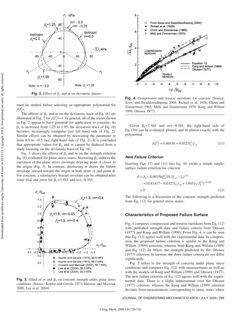
Fig. 4 compares compression and tension meridians from Eq. �12�with published strength data and failure criteria from Ottosen�1977� and Kang and Willam �1999�. From Fig. 4, it can be seenthat Eq. �12� agrees well with the experimental data. In compres-sion, the proposed failure criterion is similar to the Kang andWillam �1999� criterion, whereas both Kang and Willam �1999�and Eq. �12� lie below the strength predicted by the Ottosen�1977� criterion. In tension, the three failure criteria do not differsignificantly.
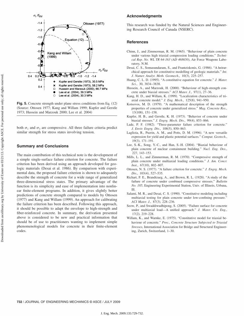
Fig. 5 refers to the strength of concrete under plane stressconditions and compares Eq. �12� with measurements as well aswith the models of Kang and Willam �1999� and Ottosen �1977�.The new failure criterion of Eq. �12� agrees well with the experi-mental data. There is a slight improvement over the Ottosen�1977� criterion, whereas the Kang and Willam �1999� criterion
Fig. 4. Compression and tension meridians for concrete �Source:Seow and Swaddiwudhipong 2005; Richart et al. 1928; Chinn andZimmerman 1965; Mills and Zimmerman 1970; Kang and Willam1999; Ottosen 1977�
deviates from measurements corresponding to stress states where
URNAL OF ENGINEERING MECHANICS © ASCE / JULY 2009 / 731
35:729-732.
Dow
nloa
ded
from
asc
elib
rary
.org
by
Uni
vers
ity o
f E
xete
r on
03/
21/1
3. C
opyr
ight
ASC
E. F
or p
erso
nal u
se o
nly;
all
righ
ts r
eser
ved.
both �1 and �3 are compressive. All three failure criteria predictsimilar strength for stress states involving tension.
Summary and Conclusions
The main contribution of this technical note is the development ofa simple single-surface failure criterion for concrete. The failurecriterion has been derived using an approach developed for geo-logic materials �Desai et al. 1986�. By comparison with experi-mental data, the proposed failure criterion is shown to adequatelydescribe the strength of concrete for a wide range of generalizedthree-dimensional stress states. The primary advantage of thefunction is its simplicity and ease of implementation into nonlin-ear finite-element programs. In addition, it gives slightly betterpredictions of concrete strength compared to models by Ottosen�1977� and Kang and Willam �1999�. An approach for calibratingthe failure criterion has been described. Following this approach,it should be possible to adapt the envelope to high-strength andfiber-reinforced concrete. In summary, the derivation presentedabove is considered to be new and practical information thatshould be of use to practitioners wanting to implement simplephenomenological models for concrete in their finite-element
Fig. 5. Concrete strength under plane stress conditions from Eq. �12��Source: Ottosen 1977; Kang and Willam 1999; Kupfer and Gerstle1973; Hussein and Marzouk 2000; Lee et al. 2004�
codes.
732 / JOURNAL OF ENGINEERING MECHANICS © ASCE / JULY 2009
J. Eng. Mech. 2009.1
Acknowledgments
This research was funded by the Natural Sciences and Engineer-ing Research Council of Canada �NSERC�.
References
Chinn, J., and Zimmerman, R. M. �1965�. “Behaviour of plain concreteunder various high triaxial compression loading conditions.” Techni-cal Rep. No. WL TR 64-163 (AD 468650), Air Force Weapons Labo-ratory, N.M.
Desai, C. S., Somasundaram, S., and Frantziskonis, G. �1986�. “A heirar-chical approach for constitutive modelling of geologic materials.” Int.J. Numer. Analyt. Meth. Geomech., 10�3�, 225–257.
Huang, C. L. D. �1995�. “A constitutive equation for concrete.” J. Mater.Sci., 30, 3834–3838.
Hussein, A., and Marzouk, H. �2000�. “Behaviour of high-strength con-crete under biaxial stresses.” ACI Mater. J., 97�1�, 27–36.
Kang, H. D., and Willam, K. �1999�. “Localization characteristics of tri-axial concrete model.” J. Eng. Mech., 125�8�, 941–950.
Kotsovos, M. D. �1979�. “A mathematical description of the strengthproperties of concrete under generalized stress.” Mag. Concrete Res.,13�108�, 151–158.
Kupfer, H. B., and Gerstle, K. H. �1973�. “Behavior of concrete underbiaxial stresses.” J. Engrg. Mech. Div., 99�4�, 853–866.
Lade, P. F. �1982�. “Three-parameter failure criterion for concrete.”J. Envir. Engrg. Div., 108�5�, 850–863.
Laglioia, R., Puzrin, A. M., and Potts, D. M. �1996�. “A new versatileexpression for yield and plastic potential surfaces.” Comput. Geotech.,19�3�, 171–191.
Lee, S.-K., Song, Y.-C., and Han, S.-H. �2004�. “Biaxial behaviour ofplain concrete of nuclear containment building.” Nucl. Eng. Des.,227, 143–153.
Mills, L. L., and Zimmerman, R. M. �1970�. “Compressive strength ofplain concrete under multiaxial loading conditions.” J. Am. Concr.Inst., 67�10�, 802–807.
Ottosen, N. S. �1977�. “A failure criterion for concrete.” J. Engrg. Mech.Div., 103�4�, 527–535.
Richart, F. E., Brandtzaeg, A., and Brown, R. L. �1928�. “A study of thefailure of concrete under combined compressive stresses.” BulletinNo. 185, Engineering Experimental Station, Univ. of Illinois, Urbana,Ill.
Salami, M. R., and Desai, C. S. �1990�. “Constitutive modeling includingmultiaxial testing for plain concrete under low-confining pressure.”ACI Mater. J., 87�3�, 228–236.
Seow, P., and Swaddiwudhipong, S. �2005�. “Failure surface for concreteunder multiaxial load—A unified approach.” J. Mater. Civ. Eng.,17�2�, 219–228.
Willam, K., and Warnke, E. �1975�. “Constitutive model for triaxial be-haviour of concrete.” Proc., Concrete Structure Subjected to TriaxialStresses, International Association for Bridge and Structural Engineer-
ing, Zurich, Switzerland, 1–30.35:729-732.