Embed Size (px)
Citation preview

This is an electronic reprint of the original article.This reprint may differ from the original in pagination and typographic detail.
Powered by TCPDF (www.tcpdf.org)
This material is protected by copyright and other intellectual property rights, and duplication or sale of all or part of any of the repository collections is not permitted, except that material may be duplicated by you for your research use or educational purposes in electronic or print form. You must obtain permission for any other use. Electronic or print copies may not be offered, whether for sale or otherwise to anyone who is not an authorised user.
Scotti, Gianmario; Kanninen, Petri; Kallio, Tanja; Franssila, SamiSimple Stacking Methods for Silicon Micro Fuel Cells
Published in:MICROMACHINES
DOI:10.3390/mi5030558
Published: 01/01/2014
Document VersionPublisher's PDF, also known as Version of record
Published under the following license:CC BY
Please cite the original version:Scotti, G., Kanninen, P., Kallio, T., & Franssila, S. (2014). Simple Stacking Methods for Silicon Micro Fuel Cells.MICROMACHINES, 5(3), 558-569. https://doi.org/10.3390/mi5030558
Micromachines 2014, 5, 558-569; doi:10.3390/mi5030558
micromachines ISSN 2072-666X
www.mdpi.com/journal/micromachines
Article
Simple Stacking Methods for Silicon Micro Fuel Cells
Gianmario Scotti 1,*, Petri Kanninen 2, Tanja Kallio 2 and Sami Franssila 1
1 Department of Materials Science & Engineering, Aalto University, P.O. Box 16200, FI-00076
Aalto, Finland; E-Mail: [email protected] 2 Department of Chemistry, Aalto University, P.O. Box 16100, FI-00076 Aalto, Finland;
E-Mails: [email protected] (P.K.); [email protected] (T.K.)
* Author to whom correspondence should be addressed; E-Mail: [email protected];
Tel.: +358-50-363-2739.
Received: 3 July 2014; in revised form: 12 August 2014 / Accepted: 18 August 2014 / Published: 21 August 2014
Abstract: We present two simple methods, with parallel and serial gas flows, for the
stacking of microfabricated silicon fuel cells with integrated current collectors, flow fields
and gas diffusion layers. The gas diffusion layer is implemented using black silicon. In the
two stacking methods proposed in this work, the fluidic apertures and gas flow topology
are rotationally symmetric and enable us to stack fuel cells without an increase in the
number of electrical or fluidic ports or interconnects. Thanks to this simplicity and the
structural compactness of each cell, the obtained stacks are very thin (~1.6 mm for a
two-cell stack). We have fabricated two-cell stacks with two different gas flow topologies
and obtained an open-circuit voltage (OCV) of 1.6 V and a power density of 63 mW·cm−2,
proving the viability of the design.
Keywords: silicon; micro fuel cell; stacking; deep reactive ion etching; polymer
electrolyte membrane; black silicon
1. Introduction
Fuel cells have been traditionally used for stationary power generation or in electrical vehicles, but
miniaturized micro fuel cells (micro FC) have been, more recently, researched as a viable alternative to
rechargeable batteries for applications, such as mobile phones, MP3 players, camcorders, etc., due to
the potentially higher energy density [1,2]. In order to compare a micro FC-based power source to
traditional Li-ion batteries in portable applications, both the volume and weight of the fuel reservoir
OPEN ACCESS
Micromachines 2014, 5 559
and the micro FC have to be taken into consideration. In micro FCs used for portable applications,
operating temperatures are lower than in macro fuel cells (used in automotive and cogeneration
technologies), and hence, the power density (per area) is lower, as well. To compensate, the small size
of micro FCs should be utilized as much as possible: with smaller fuel cells, the per-volume power
density increases. To achieve sufficient power density and voltage, a number of micro FCs should be
stacked. There is an additional benefit of having multiple smaller fuel cells rather than one large one:
to minimize the effect of defects in microfabrication, which is the same argument as the one used in
the microelectronic industry to have a large number of chips per wafer.
One possible approach for adding and combining multiple micro FCs to a microfabricated power
source is to concatenate them in a planar or co-planar structure (such as in [3–13]), in which case there
is no real stack, but rather a cluster of micro FCs placed laterally next to each other in the same plane.
This approach is often used in microfabrication, because it will simplify either the placement and
fabrication of gas interconnects or the placement and fabrication of electrical interconnects. However,
it will not simplify the fabrication of both. This type of structure suffers from lateral ionic inter-cell
conduction through the electrolyte (such as a proton exchange membrane, PEM) and has to be taken
care of by patterning the electrolyte. Furthermore, it is often not desirable to have a planar structure,
because of form factor restrictions. Finally, compared to vertical stacks, planar micro FC stacks have
the disadvantage of being harder to isolate thermally due to a larger surface-to-volume ratio.
Sustaining high temperatures is important for achieving high reaction rates and, thus, the high
performance of a fuel cell. This thermal advantage of vertical vs. planar micro FC stacks has been fully
utilized in [14], where two micro solid oxide fuel cells (SOFC) operating at 600 °C have been
vertically stacked and thermally isolated.
Some examples of vertically stacked micro FC studies do exist [14–17]. In the macro world,
vertically-stacked fuel cells are the norm, while planar stacks are almost unheard of. The reason for the
predominance of planar stacks with microfabricated fuel cells is the structural overhead that electrical
and fluidic interconnects impose on the design. In [15], an attempt was made to reduce this overhead,
by having a shared anode plate, where a single methanol channel serves as the flow field for two
cathodes, whereas in [14], the simplicity is a consequence of using a single-chamber configuration,
where both the cathode and the anode are placed in the same container with fuel and oxidant. These
designs are restricted to two cells per stack.
No such restriction in the number of stacked cells exists for the devices described in [16,17].
These micro FC stacks use a configuration known as “bipolar plates”, where the flow field plates are
conductive and stacked in such a way as to add to the voltage of the cells. Both solutions take care of
the distribution of reactants (oxidant and fuel) to all of the cells: in [16], this was achieved by
pumping, while in [17], the cells are self-breathing and the liquid fuel is pumped by CO2 bubble
formation at the anode.
Our designs allow for theoretically unlimited numbers of fuel cells per stack. One of these designs
uses the same flow topology as [16] (which we call “parallel”), whereas our other solution, “serial”,
has not been used in micro fuel cells before. In this case, the fuel flows sequentially from one cell to
the next (Figure 1). The serial topology was introduced by us in a conference paper [18], but the
current design is much smaller, mechanically more robust and less prone to leaks.
Micromachines 2014, 5 560
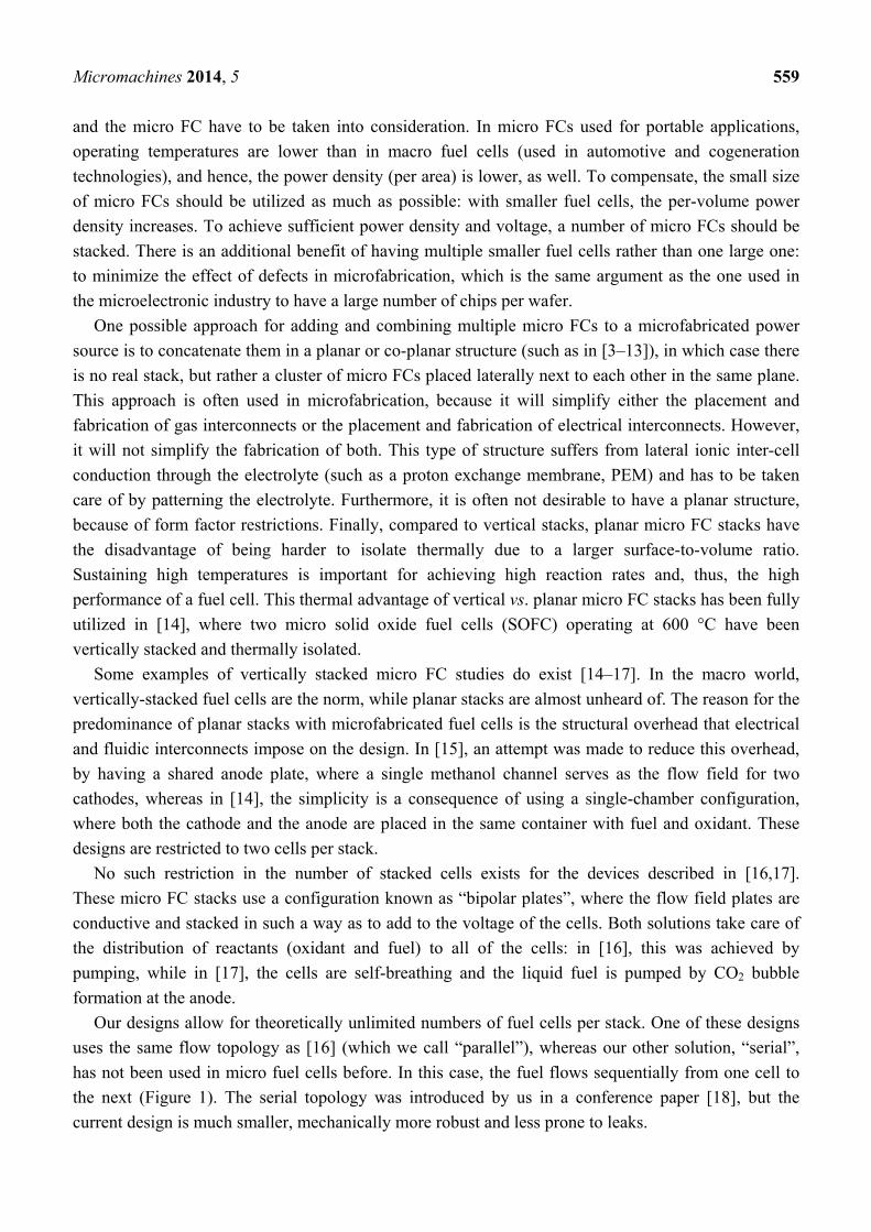
Figure 1. Illustration of serial vs. parallel gas flow topologies: in the case of serial flow,
the reactant gases pass from one cell to the next, while in the case of parallel flow, all of
the cells are supplied simultaneously.
In a previous work [19], we reported on a simplified structure of a single-cell silicon micro FC. This
simplification was achieved by using a single silicon chip simultaneously as a current collector, gas
flow field and gas diffusion layer (GDL). That arrangement makes them also candidates for bipolar
plates. In this work, we show that redesigning the fluidic apertures and using rotational symmetry
allows for easy stacking of micro FCs. The stackable cells are identical, but rotated by 180 degrees
with respect to each other. A two-cell stack produces 1.6 V of open-circuit voltage (OCV), about
double the single hydrogen-fueled cell OCV.
2. Experimental Section
2.1. Construction and Principle of Operation
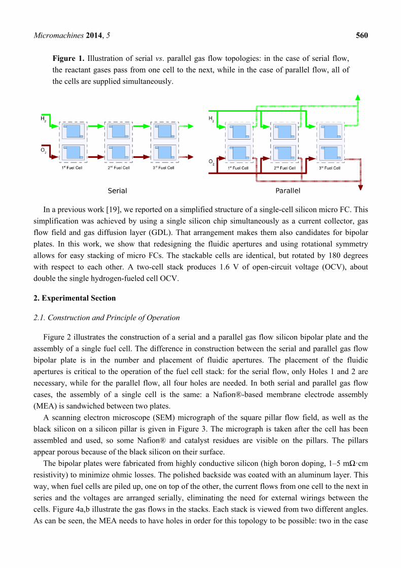
Figure 2 illustrates the construction of a serial and a parallel gas flow silicon bipolar plate and the
assembly of a single fuel cell. The difference in construction between the serial and parallel gas flow
bipolar plate is in the number and placement of fluidic apertures. The placement of the fluidic
apertures is critical to the operation of the fuel cell stack: for the serial flow, only Holes 1 and 2 are
necessary, while for the parallel flow, all four holes are needed. In both serial and parallel gas flow
cases, the assembly of a single cell is the same: a Nafion®-based membrane electrode assembly
(MEA) is sandwiched between two plates.
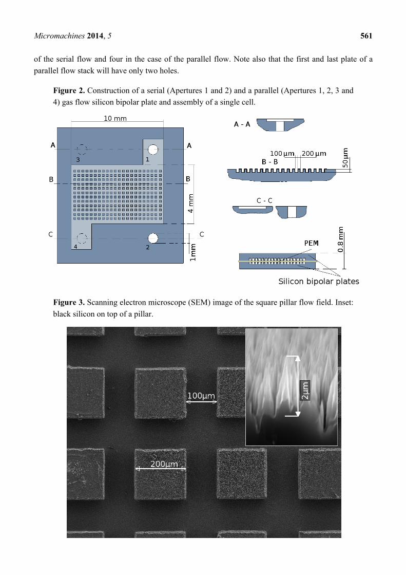
A scanning electron microscope (SEM) micrograph of the square pillar flow field, as well as the
black silicon on a silicon pillar is given in Figure 3. The micrograph is taken after the cell has been
assembled and used, so some Nafion® and catalyst residues are visible on the pillars. The pillars
appear porous because of the black silicon on their surface.
The bipolar plates were fabricated from highly conductive silicon (high boron doping, 1–5 mΩ·cm
resistivity) to minimize ohmic losses. The polished backside was coated with an aluminum layer. This
way, when fuel cells are piled up, one on top of the other, the current flows from one cell to the next in
series and the voltages are arranged serially, eliminating the need for external wirings between the
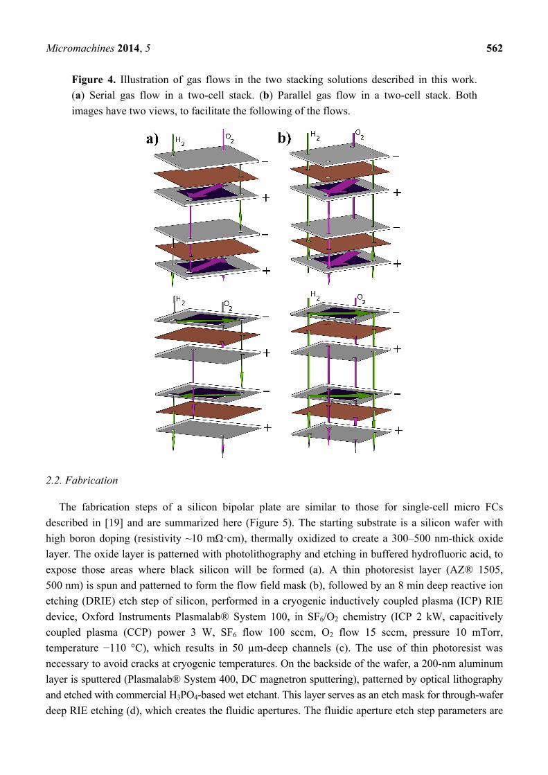
cells. Figure 4a,b illustrate the gas flows in the stacks. Each stack is viewed from two different angles.
As can be seen, the MEA needs to have holes in order for this topology to be possible: two in the case
Micromachines 2014, 5 561
of the serial flow and four in the case of the parallel flow. Note also that the first and last plate of a
parallel flow stack will have only two holes.
Figure 2. Construction of a serial (Apertures 1 and 2) and a parallel (Apertures 1, 2, 3 and
4) gas flow silicon bipolar plate and assembly of a single cell.
Figure 3. Scanning electron microscope (SEM) image of the square pillar flow field. Inset:
black silicon on top of a pillar.
Micromachines 2014, 5 562
Figure 4. Illustration of gas flows in the two stacking solutions described in this work.
(a) Serial gas flow in a two-cell stack. (b) Parallel gas flow in a two-cell stack. Both
images have two views, to facilitate the following of the flows.
2.2. Fabrication
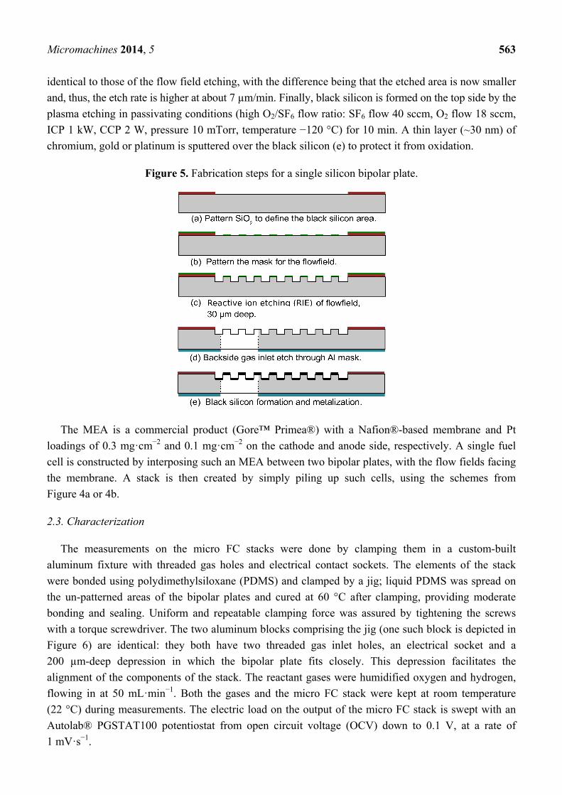
The fabrication steps of a silicon bipolar plate are similar to those for single-cell micro FCs
described in [19] and are summarized here (Figure 5). The starting substrate is a silicon wafer with
high boron doping (resistivity ~10 mΩ·cm), thermally oxidized to create a 300–500 nm-thick oxide
layer. The oxide layer is patterned with photolithography and etching in buffered hydrofluoric acid, to
expose those areas where black silicon will be formed (a). A thin photoresist layer (AZ® 1505,
500 nm) is spun and patterned to form the flow field mask (b), followed by an 8 min deep reactive ion
etching (DRIE) etch step of silicon, performed in a cryogenic inductively coupled plasma (ICP) RIE
device, Oxford Instruments Plasmalab® System 100, in SF6/O2 chemistry (ICP 2 kW, capacitively
coupled plasma (CCP) power 3 W, SF6 flow 100 sccm, O2 flow 15 sccm, pressure 10 mTorr,
temperature −110 °C), which results in 50 µm-deep channels (c). The use of thin photoresist was
necessary to avoid cracks at cryogenic temperatures. On the backside of the wafer, a 200-nm aluminum
layer is sputtered (Plasmalab® System 400, DC magnetron sputtering), patterned by optical lithography
and etched with commercial H3PO4-based wet etchant. This layer serves as an etch mask for through-wafer
deep RIE etching (d), which creates the fluidic apertures. The fluidic aperture etch step parameters are
Micromachines 2014, 5 563
identical to those of the flow field etching, with the difference being that the etched area is now smaller
and, thus, the etch rate is higher at about 7 µm/min. Finally, black silicon is formed on the top side by the
plasma etching in passivating conditions (high O2/SF6 flow ratio: SF6 flow 40 sccm, O2 flow 18 sccm,
ICP 1 kW, CCP 2 W, pressure 10 mTorr, temperature −120 °C) for 10 min. A thin layer (~30 nm) of
chromium, gold or platinum is sputtered over the black silicon (e) to protect it from oxidation.
Figure 5. Fabrication steps for a single silicon bipolar plate.
The MEA is a commercial product (Gore™ Primea®) with a Nafion®-based membrane and Pt
loadings of 0.3 mg·cm−2 and 0.1 mg·cm−2 on the cathode and anode side, respectively. A single fuel
cell is constructed by interposing such an MEA between two bipolar plates, with the flow fields facing
the membrane. A stack is then created by simply piling up such cells, using the schemes from
Figure 4a or 4b.
2.3. Characterization
The measurements on the micro FC stacks were done by clamping them in a custom-built
aluminum fixture with threaded gas holes and electrical contact sockets. The elements of the stack
were bonded using polydimethylsiloxane (PDMS) and clamped by a jig; liquid PDMS was spread on
the un-patterned areas of the bipolar plates and cured at 60 °C after clamping, providing moderate
bonding and sealing. Uniform and repeatable clamping force was assured by tightening the screws
with a torque screwdriver. The two aluminum blocks comprising the jig (one such block is depicted in
Figure 6) are identical: they both have two threaded gas inlet holes, an electrical socket and a
200 µm-deep depression in which the bipolar plate fits closely. This depression facilitates the
alignment of the components of the stack. The reactant gases were humidified oxygen and hydrogen,
flowing in at 50 mL·min−1. Both the gases and the micro FC stack were kept at room temperature
(22 °C) during measurements. The electric load on the output of the micro FC stack is swept with an
Autolab® PGSTAT100 potentiostat from open circuit voltage (OCV) down to 0.1 V, at a rate of
1 mV·s−1.

Micromachines 2014, 5 564
Figure 6. An aluminum block, part of the stack measurement fixture. The jig is comprised
of two such blocks.
3. Results and Discussion
Both serial and parallel flow stacks were characterized. Figure 7 shows post-mortem photographs of
a serial flow stack (a) and a parallel flow silicon bipolar plate (b).
As was mentioned, the last step in fabricating a flow field body is deposition of a thin layer of
chromium or platinum on the black silicon GDL. The function of this metal layer is to protect the black
silicon from oxidation, which would deteriorate the performance of the fuel cell. The thin metal layer
additionally reduces the electrical resistance of the GDL. Measurements on single cells [19] have
demonstrated no difference in performance whether using chromium or platinum for metallization,
hence chromium, as the cheaper material, has been chosen for the stackable fuel cell metallization.
Even though chromium develops a thin oxide layer when exposed to air, this oxide is
electron-conductive, and therefore, the metallization is suitable for our purposes.
Figure 7. Photograph of a serial flow stack (a) and a parallel flow silicon bipolar plate (b)
removed from a stack. Both photographs were taken after characterization. The 1 EUR
coin is for size comparison.
Micromachines 2014, 5 565
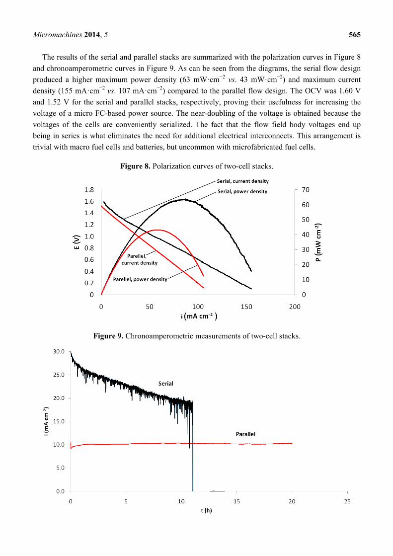
The results of the serial and parallel stacks are summarized with the polarization curves in Figure 8
and chronoamperometric curves in Figure 9. As can be seen from the diagrams, the serial flow design
produced a higher maximum power density (63 mW·cm−2 vs. 43 mW·cm−2) and maximum current
density (155 mA·cm−2 vs. 107 mA·cm−2) compared to the parallel flow design. The OCV was 1.60 V
and 1.52 V for the serial and parallel stacks, respectively, proving their usefulness for increasing the
voltage of a micro FC-based power source. The near-doubling of the voltage is obtained because the
voltages of the cells are conveniently serialized. The fact that the flow field body voltages end up
being in series is what eliminates the need for additional electrical interconnects. This arrangement is
trivial with macro fuel cells and batteries, but uncommon with microfabricated fuel cells.
Figure 8. Polarization curves of two-cell stacks.
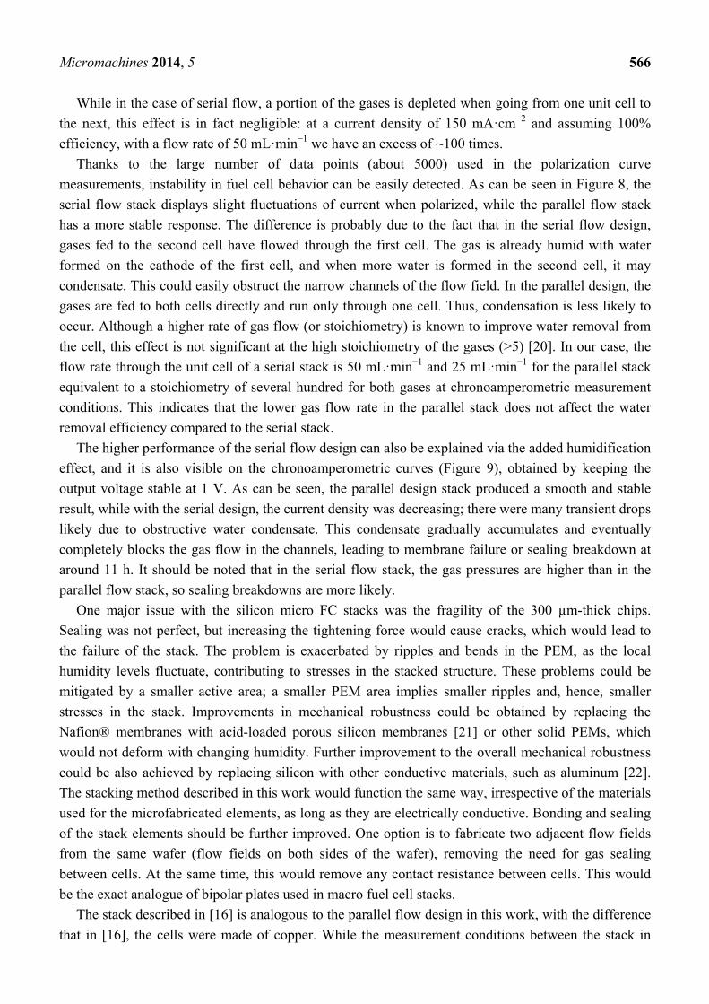
Figure 9. Chronoamperometric measurements of two-cell stacks.
Micromachines 2014, 5 566
While in the case of serial flow, a portion of the gases is depleted when going from one unit cell to
the next, this effect is in fact negligible: at a current density of 150 mA·cm−2 and assuming 100%
efficiency, with a flow rate of 50 mL·min−1 we have an excess of ~100 times.
Thanks to the large number of data points (about 5000) used in the polarization curve
measurements, instability in fuel cell behavior can be easily detected. As can be seen in Figure 8, the
serial flow stack displays slight fluctuations of current when polarized, while the parallel flow stack
has a more stable response. The difference is probably due to the fact that in the serial flow design,
gases fed to the second cell have flowed through the first cell. The gas is already humid with water
formed on the cathode of the first cell, and when more water is formed in the second cell, it may
condensate. This could easily obstruct the narrow channels of the flow field. In the parallel design, the
gases are fed to both cells directly and run only through one cell. Thus, condensation is less likely to
occur. Although a higher rate of gas flow (or stoichiometry) is known to improve water removal from
the cell, this effect is not significant at the high stoichiometry of the gases (>5) [20]. In our case, the
flow rate through the unit cell of a serial stack is 50 mL·min−1 and 25 mL·min−1 for the parallel stack
equivalent to a stoichiometry of several hundred for both gases at chronoamperometric measurement
conditions. This indicates that the lower gas flow rate in the parallel stack does not affect the water
removal efficiency compared to the serial stack.
The higher performance of the serial flow design can also be explained via the added humidification
effect, and it is also visible on the chronoamperometric curves (Figure 9), obtained by keeping the
output voltage stable at 1 V. As can be seen, the parallel design stack produced a smooth and stable
result, while with the serial design, the current density was decreasing; there were many transient drops
likely due to obstructive water condensate. This condensate gradually accumulates and eventually
completely blocks the gas flow in the channels, leading to membrane failure or sealing breakdown at
around 11 h. It should be noted that in the serial flow stack, the gas pressures are higher than in the
parallel flow stack, so sealing breakdowns are more likely.
One major issue with the silicon micro FC stacks was the fragility of the 300 µm-thick chips.
Sealing was not perfect, but increasing the tightening force would cause cracks, which would lead to
the failure of the stack. The problem is exacerbated by ripples and bends in the PEM, as the local
humidity levels fluctuate, contributing to stresses in the stacked structure. These problems could be
mitigated by a smaller active area; a smaller PEM area implies smaller ripples and, hence, smaller
stresses in the stack. Improvements in mechanical robustness could be obtained by replacing the
Nafion® membranes with acid-loaded porous silicon membranes [21] or other solid PEMs, which
would not deform with changing humidity. Further improvement to the overall mechanical robustness
could be also achieved by replacing silicon with other conductive materials, such as aluminum [22].
The stacking method described in this work would function the same way, irrespective of the materials
used for the microfabricated elements, as long as they are electrically conductive. Bonding and sealing
of the stack elements should be further improved. One option is to fabricate two adjacent flow fields
from the same wafer (flow fields on both sides of the wafer), removing the need for gas sealing
between cells. At the same time, this would remove any contact resistance between cells. This would
be the exact analogue of bipolar plates used in macro fuel cell stacks.
The stack described in [16] is analogous to the parallel flow design in this work, with the difference
that in [16], the cells were made of copper. While the measurement conditions between the stack in
Micromachines 2014, 5 567
this work and in [16] differ (back pressure, use of air instead of O2 and temperature of the stack), it is
evident that the current and power densities obtained are comparable to ours: the authors in [16]
obtained power densities in the range of 40–60 mW·cm−2 and current densities in the range of
160–220 mA·cm−2. The authors did not perform chronoamperometric measurements, so the sustained
performance of their stack cannot be determined. Since copper is a much more ductile material
compared to silicon, it is likely that the stack in [16] was less fragile and that leaks could be avoided by
simply tightening down the stack with sufficient force. Copper is also much more conductive than
highly-doped silicon.
4. Conclusions
We have demonstrated a straight-forward method for obtaining vertical micro FC stacks. Our
experimental results show that the two-cell stack OCV is 1.60 V, nearly double the single-cell OCV,
and the design is amenable to further stacking, due to its inherent simplicity. Both serial and parallel
gas flow designs are shown to produce working devices, with 155 mA·cm−2 and 107 mA·cm−2
maximum current densities and 63 mW·cm−2 and 43 mW·cm−2 maximum power densities for the
parallel and serial designs, respectively, though the parallel flow design produces more stable results.
Our designs permit the free mixing and matching of the serial and parallel flow of fluids, which should
be utilized to optimize fuel consumption and current density. It should be noted that the fluidic
distribution network is nothing more than simple through-wafer holes, which can be made arbitrarily
large and, hence, accommodate any desired flux.
Both serial and parallel flow designs theoretically allow for large numbers of micro FCs stacked on
top of each other. If the water management problems could be solved in the case of serial flow, the
oxidant and fuel will be depleted after a certain number of cells, which leads to better fuel efficiency,
but lower current density. With the parallel flow design, the current density remains the same, but the
fuel may not be completely utilized.
The losses in electrical contacts need to be studied and the gas losses reduced by more elaborate
bonding and sealing structures. Ways to improve mechanical strength should be also researched.
Higher performance and multiple cell stacks are expected to be realized in the future. These devices
will have smaller area bipolar plates and membranes to increase the robustness and to achieve
greater miniaturization.
Acknowledgments
This work was supported by Academy of Finland (#13253223, #251629 and #266820) and Aalto
University’s Multidisciplinary Institute of Digitalisation and Energy (MIDE) program. The cleanroom
facilities of Micronova, Center for Micro and Nanotechnology, were used for device fabrication.
Author Contributions
Gianmario Scotti designed the devices and the experiments, performed the microfabrication, wrote
large parts of the manuscript, authored almost all of the illustrations and edited the article as a whole.
Petri Kanninen was responsible for designing and performing the electrochemical measurements and
Micromachines 2014, 5 568
wrote the majority of the material about fuel cell behavior.Tanja Kallio assisted with fuel cell theory,
and Sami Franssila contributed to the article as a whole.
Conflicts of Interest
The authors declare no conflict of interest.
References
1. Kjeang, E.; Djilali, N.; Sinton, D. Microfluidic fuel cells: A review. J. Power Sources 2009, 186,
353–369.
2. Wang, Y.; Chen, K.S.; Mishler, J.; Cho, S.C.; Adroher, X.C. A review of polymer electrolyte
membrane fuel cells: Technology, applications, and needs on fundamental research. Appl. Energ. 2011, 88, 981–1007.
3. Min, K.-B.; Tanaka, S.; Esashi, M. Fabrication of novel MEMS-based polymer electrolyte fuel
cell architectures with catalytic electrodes supported on porous SiO2. J. Micromech. Microeng. 2006, 16, 505–511.
4. Lee, S.J.; Chang-Chien, A.; Cha, S.W.; O’Hayre, R.; Park, Y.I.; Saito, Y.; Prinz, F.B. Design and
fabrication of a micro fuel cell array with “flip-flop” interconnection. J. Power Sources 2002, 112,
410–418.
5. Hahn, R.; Wagner, S.; Schmitz, A.; Reichl, H. Development of a planar micro fuel cell with thin
film and micro patterning technologies. J. Power Sources 2004, 131, 73–78.
6. Pratt, S.D.; Kelley, R.J.; Muthuswamy, S.; Landreth, B.D.; Pennisi, R.W. Planar fuel cell.
U.S. Patent 6,127,058, 3 October 2000.
7. Kim, D.; Cho, E.A.; Hong, S.-A.; Oh, I.-H.; Ha, H.Y. Recent progress in passive direct methanol
fuel cells at KIST. J. Power Sources 2004, 130, 172–177.
8. Liu, X.; Zhang, B.; Zhang, Y.; He, H.; Li, J.; Wang, S.; Yuan, Z.; Deng, H. Development and
characterization of a novel air-breathing micro direct methanol fuel cell stack for portable
applications. J. Micromech. Microeng. 2010, 20, 104008.
9. Kim, S.H.; Cha, H.Y.; Miesse, C.M.; Jang, J.H.; Oh, Y.S.; Cha, S.W. Air-breathing miniature
planar stack using the flexible printed circuit board as a current collector. Int. J. Hydrogen Energ. 2009, 34, 459–466.
10. Cao, J.; Zou, Z.; Huang, Q.; Yuan, T.; Li, Z.; Xia, B.; Yang, H. Planar air-breathing micro-direct
methanol fuel cell stacks based on micro-electronic–mechanical-system technology. J. Power Sources 2008, 185, 433–438.
11. Feng, L.; Cai, W.; Li, C.; Zhang, J.; Liu, C.; Xing, W. Fabrication and performance evaluation for
a novel small planar passive direct methanol fuel cell stack. Fuel 2012, 94, 401–408.
12. Hsieh, S.-S.; Huang, C.-C. Design, fabrication and performance test of a planar array module-type
micro fuel cell stack. Energ. Convers. Manag. 2013, 76, 971–979.
13. Ho, B.; Kjeang, E. Planar Multiplexing of Microfluidic Fuel Cells. J. Fluid Eng. 2013, 135, 021304.
14. Shao, Z.; Haile, S. M.; Ahn, J.; Ronney, P.D.; Zhan, Z.; Barnett, S.A. A thermally self-sustained
micro solid-oxide fuel-cell stack with high power density. Nature 2005, 435, 795–798.
Micromachines 2014, 5 569
15. Zhong, L.; Wang, X.; Jiang, Y.; Zhang, Q.; Qiu, X.; Zhou, Y.; Liu, L. A micro-direct methanol
fuel cell stack with optimized design and microfabrication. Sens. Actuators A. 2008, 143, 70–76.
16. Hsieh, S.-S.; Feng, C.-L.; Huang, C.-F. Development and performance analysis of a H2/air micro
PEM fuel cell stack. J. Power Sources 2006, 163, 440–449.
17. Sun, L.; Liu, C.; Liang, J.; Zhu, X.; Cui, T. A self-pumping and self-breathing micro direct
methanol fuel cell with polymer bipolar plates. J. Power Sources 2011, 196, 7533–7540.
18. Scotti, G.; Kanninen, P.; Kallio, T.; Franssila, S. A micro fuel cell stack without interconnect
overhead - macro world-like stacks in MEMS. In Proceedings of 21st Micromechanics and Micro
systems Europe (MME2010), Enschede, The Netherlands, 26–29 September 2010; pp. 161–164.
19. Scotti, G.; Kanninen, P.; Mäkinen, M.; Kallio, T.; Franssila, S. Silicon nanograss as micro fuel
cell gas diffusion layer. Micro Nano Lett. 2010, 5, 382–385.
20. Wang, Y.; Basu, S.; Wang, C.-Y. Modeling two-phase flow in PEM fuel cell channels. J. Power Sources 2008, 179, 603–617.
21. Chu, K.-L.; Shannon, M.A.; Masel, R. Porous silicon fuel cells for micro power generation.
J. Micromech. Microeng. 2007, 17, S243–S249.
22. Scotti, G.; Kanninen, P.; Kallio, T.; Franssila, S. Bulk-Aluminum Microfabrication for Micro Fuel
Cells. J. Microelectromech. S. 2014, 23, 372–379.
© 2014 by the authors; licensee MDPI, Basel, Switzerland. This article is an open access article
distributed under the terms and conditions of the Creative Commons Attribution license
(http://creativecommons.org/licenses/by/3.0/).